

Page 1

98648-012-08
Operation Manual
Sartorius Basic Meter PB-11
Page 2

Page 3

3
Contents
4 General View
6 Warning and Safety Information
7 Installing and Maintaining Electrodes
9 Standardizing for pH Measurement
13 Using Setup
15 Standardizing for Millivolt Measurement
18 Understanding pH Theory
19 Temperature Compensation
20 Measuring pH
21 Troubleshooting
23 Meter Specifications
24 Accessories
25 C Declaration of Conformity
Page 4

4
General View
1 Setup button:
Press to clear buffers,
review electrode
calibration or select new
autorecognized buffers
2 Mode button:
Press to toggle between
pH and mV mode
3 Standardize button:
Press to enter each buffer
4 Enter button:
Press to select menu
item options
5 Measuring icon
6 Temperature
7 Mode
8 Result
9 Prompts
10 Buffer icons
11 Icon: standardization
(calibration of the meter)
in process
12 Stability icon
13 Standardizing icon
14 Standardization result
Front View
Display
1
2
3
4
1.68
4.01 6.86
9.18
12.46
S1
S2 S3
32
1
%/¡C
Auto
Man
Set
Clear
OK
Error
1234567810101213
Sal
TDS
%DO
mg/L
S/cm cm ion
rel
mV pH
m
µ
K
M
°C
S
13
12
11
10
14
5
6
7
8
9
1
2
3
Page 5
5
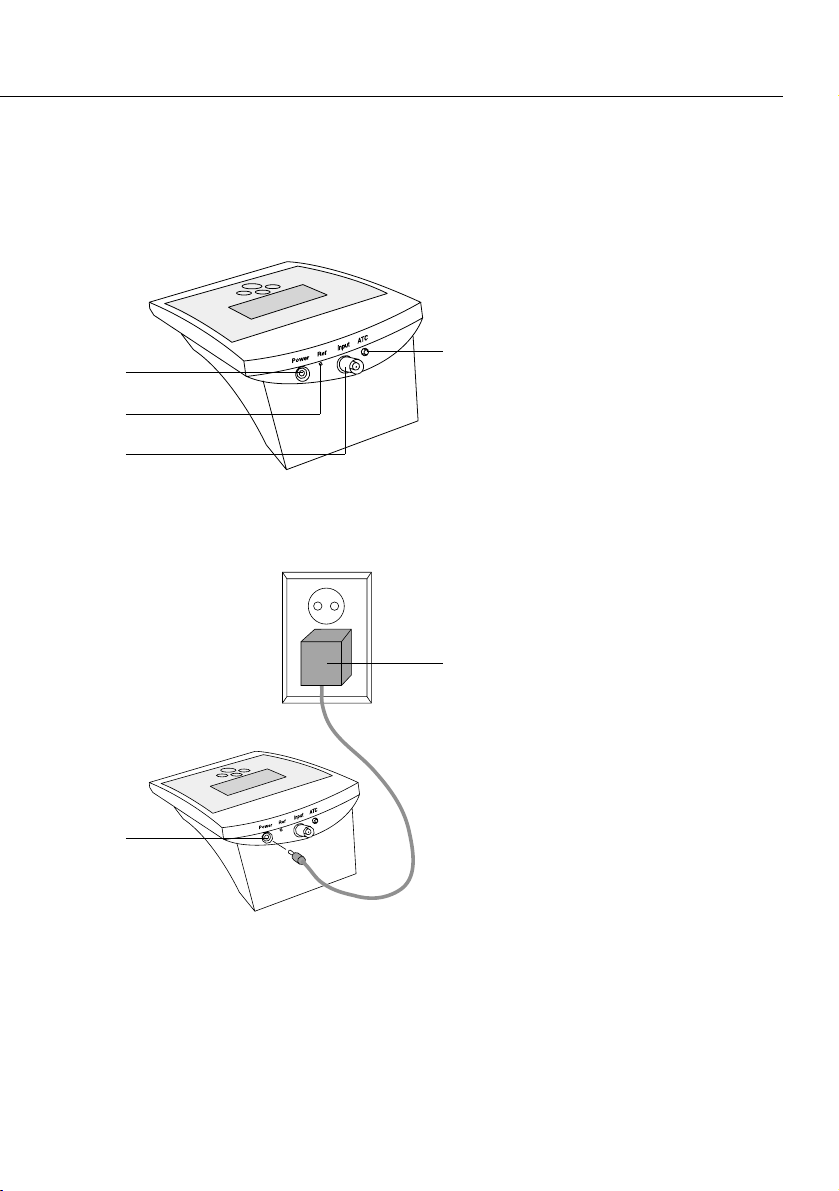
1 Power cable connector
2 Reference electrode
connector (used with
separate reference
electrodes)
3 BNC electrode connector
4 Temperature compensation
probe connector
5 AC adapter
Rear View
Connecting to a Power Source
1
2
3
4
1
5
Page 6

6
Warning and Safety Information
For safety and operating reasons, only authorized
service technicians may open the Basic Meter PB-11
housing. Therefore, only authorized technicians may
repair or perform maintenance on this pH meter.
Any tampering with the pH meter or negligent or
intentional damage to this equipment will void any
warranty claims against the manufacturer.
If liquid gets into the pH meter, unplug it from AC
power (mains supply) and have an authorized service
technician check the pH meter.
If you do not plan to use this pH meter for a relatively
long period, please disconnect it from AC power.
For safety reasons, use this equipment only for the
application described in this operation manual.
Make sure that the buffers used for standardizing
have exactly the same values that are stored.
Page 7

7
Installing and Maintaining Electrodes
1. Remove the protective end cover from the electrode.
2. Before first use of your electrode, or whenever
the electrode is dry, soak overnight in a standard
solution or KCI solution.
3. Remove the shorting cap on the pH meter connector.
Install the electrode by plugging the BNC and ATC
connectors into the jacks on the rear panel.
Page 8

8
4. Option: Install an ion selective electrode by removing
the BNC shorting cap and plugging the BNC connector
(twist-lock) into the BNC jack. If a combination
electrode is not available, plug the separate reference
electrode into the ref pin.
5. Clean the electrode between each measurement with
distilled water or deionized water, or part of the next
solution to be measured.
6. Store glass pH electrodes in KCI solution or electrode
filling solution. Make sure the liquid level of the
internal filling solution is always a few centimeters
higher than that of the measurement solution.
Reference
Electrode
ISE
Page 9

9
Standardizing for pH Measurement
Because electrodes vary in their response, you
must standardize (calibrate) your pH meter and
electrode to compensate for electrode variation.
The more frequently you standardize, the more
accurate your measurements. Standardize daily,
or more often, for accurate results.
This pH meter allows automatic standardization
using up to three buffers. Press the Standardize
button again to delete all the standardization data
stored up to that point. The pH meter performs
automatic temperature compensation.
1. Immerse electrode in a buffer solution. Stir gently.
Allow the electrode to reach a stable value.
2. Press the Mode button until your digital display
indicates pH mode. This button toggles between
pH and mV modes.
Page 10

10
3. Clear existing buffers when doing a new 2- or
3-point standardization. Use the Setup button.
Also use the Setup button to select the individual
sets of buffers. (See page 13.)
4. Press Standardize. The meter recognizes the buffer
and flashes a buffer icon. When the signal is stable,
the buffer is entered. By pressing ENTER you can
also enter the current buffer directly.
5. The meter displays the slope of the electrode as
100.0%. On entering a second or third buffer,
the meter performs a diagnostic check on the
electrode and displays the slope. (See step 7 ff.)
[Standardize]
Page 11

11
6. To enter a second buffer, place the electrode in
the second buffer solution, stir, allow time for the
electrode to stabilize, and press Standardize again.
The meter recognizes the buffer and displays the
first and second buffer values.
7. Next, the meter performs a diagnostic test of
the electrode. The display indicates either Good
Electrode (“OK”) or Electrode Error (“Error”).
The meter also displays the slope of the electrode.
8. Error indicates that your electrode or the buffer
is not working properly, or a wrong set of buffers
has been selected. The electrode response must be
between 90 and 105% slope. (See Troubleshooting,
on page 21.) Press Enter to clear the Error, then
try re-entering the buffer as described in step 6.
9. To set a third standard, place the electrode in the
third buffer solution, stir, allow to stabilize, and
press Standardize. The results will be the same
as in steps 6 and 7, except the display will show
three buffer values.
[Standardize]
[Standardize]
Page 12

12
10. After entering three buffers, the Standardizing
icon goes out and the Measuring icon appears
on the display to indicate that the meter returns
to Measuring operation.
! Note:
The meter continually adjusts for temperature.
Therefore, buffers may vary slightly from the
nominal values because of temperature.
11. Standardize your pH meter using at least two
buffers with pH values bracketing the expected pH
of your samples. Stirring with a magnetic stir bar
provides faster electrode response.
Page 13

13
Using Setup
The Setup button lets you clear all the standardization data that you have entered, review calibration
information, or select the buffer set that you want.
You can escape the setup mode at any time by
pressing pH/mV.
1. Press Setup once to clear all buffers you have
entered. If you are sure you want to clear the
buffers, press Enter. The meter clears all buffers
and returns to Measuring.
2. Press Setup again to show electrode performance,
slope and the first and second calibration points.
The two buffer values will also be displayed.
3. Pressing Setup again shows the electrode slope
between the second and third buffers (if three
buffers have been entered) and shows the second
and third buffer icons.
[Setup]
[Enter]
2+ [Setup]
Page 14

14
4. Press Setup again to display a Set Buffers icon
and to display the first buffer set icons.
5. Press Enter to select the set of buffers shown on
the display or Press Setup again to toggle between
the existing sets of buffers.
6. Press Enter to select the displayed buffer set that
contains the buffer you want to use. Press Setup
again, or press the Mode button at any time to
return to Measuring.
!Note:
You may select buffers from different sets.
[Setup] or
[Enter]
[Setup]
Page 15

15
Standardizing for
Millivolt Measurement
(Relative Millivolt)
You will normally use millivolt measurements for
determining ion concentration and for measuring
redox potential (also called ORP, oxidation reduction
potential).
You will use an ion selective electrode (ISE),
combined with a reference electrode, to measure ion
concentration. The ISE senses the ion concentration
and responds with a millivolt potential. The millivolt
readings are then used to determine ion concentrations (on the basis of a previously entered
calibration curve).
You will normally use a redox/ORP electrode to
measure redox potential (ORP). ORP measurements
indicate the oxidizing or reducing capability of a
solution. You can use ORP values to monitor or
control solutions requiring a set amount of oxidants
or reductants.
1. Immerse electrode in a standard solution.
Page 16

16
2. Press Mode until your digital display indicates
mV mode.
3. Press Standardize to enter an mV standard and
read relative mV.
4. When the signal becomes stable, or when you
press Enter, the current absolute mV value (offset)
becomes zero relative millivolts.
[Mode]
[Standardize]
Page 17

17
5. To clear an mV offset and return to absolute
millivolt mode, press Setup. The meter displays
a flashing Clear icon, and shows the current
relative millivolt offset.
6. To clear the previous mV offset, press Enter.
You then return to absolute mV mode.
[Setup]
[Enter]
Page 18

18
Understanding pH Theory
Defining pH
The measurement of pH plays an important
role in identifying and controlling acidity
and alkalinity levels for industry and
research. pH is a measure of the acidity
or alkalinity of a solution and can be
represented by this equation:
pH = -log [H
+
]
with [H
+
] representing the concentration
of hydrogen ions in the solution. pH is
sometimes referred to as the power of the
hydrogen ion in a solution.
By using a pH meter, you can determine
exact pH levels of solutions. For example,
rather than say that lemon juice is quite
acidic, you can say that lemon juice has
a pH of 2.4. An exact pH value can be
used to control or measure acidity levels
for manufacturing processes or for basic
research.
pH values generally range from 0 to14,
with a pH of 7 being the neutral point,
or the value of pure water. pH values
greater than 7 represent increasing
alkalinity, whereas pH values below 7
represent increasing acidity (Figure 1).
pH
0 Strong Acid
1
2 Lemon Juice
3
4 Tomato Juice
5 Coffee
6
Neutral 7 Pure Water
8 Baking Soda
9
(sodium hydrogen carbonate)
10
11
12 Ammonia
13
14 Strong Base
more acidicmore basic
Figure 1.
pH scale showing
the relative acidity
or basicity of some
common substances.
Page 19

19
Temperature Compensation
!Note: Automatic temperature compensation
only functions properly if a temperature probe
is connected.
Temperature compensation influences the results
in two different ways:
1. pH values of the buffers change as a function
of temperature.
Each buffer varies as a function of the temperature of the respective solution. Typically, these
values are indicated on the buffer label. The
values detailed in the table below apply to most
technical buffers.
If standardization is performed in the pH mode,
the pH value is adapted to the nominal value of
the current temperature.
For example, if the buffer has a nominal pH of
7.00 at a temperature of 25°C, the meter will
standardize the buffer to 7.02 instead of 7.00 at
a temperature of 20°C.
2. Electrode slope changes as a function of
temperature.
Theoretically, the change of voltage per pH unit
is approx. 59.16 mV at 25°C. However, this mV
per pH unit changes as a function of temperature.
The meter compensates for these changes by
taking into account the temperature dependency
of the Nernst factor when calculating pH values.
Standard buffers:
pH 4.00 pH 7.00 pH 10.00
0°C 4.005 7.13 10.34
5°C 4.003 7.10 10.26
10°C 4.001 7.07 10.19
15°C 4.002 7.05 10.12
20°C 4.003 7.02 10.06
25°C 4.008 7.00 10.00
30°C 4.010 6.99 9.94
35°C 4.020 6.98 9.90
40°C 4.030 6.97 9.85
50°C 4.061 6.97 9.78
Page 20

20
Measuring pH
To measure pH with a conventional glass pH electrode, the
meter uses a pH-sensing glass
bulb that is sensitive to hydrogen
ions. The potential developed at
the glass membrane is directly
related to the pH of the solution.
The glass electrode is paired
with a reference electrode
which completes the electrical
measuring circuit and provides
a stable reference point. These
two electrodes are joined to
create a combination electrode.
The combination glass electrode
is connected to the pH meter
which reads the voltage, converts
it to pH units, and displays the
result.
Reference
Electrode
Porous
Junction
(Diaphragm)
pH Sensor
Temperature sensor
with automatic temperature
compensation (ATC)
Page 21

21
Troubleshooting
1. If the signal from the electrode is out of range, the
display will show “——”. This may happen when the
electrode is not immersed in a solution.
2. The meter will display Error when it detects an
error in electrode response. During standardization,
the message indicates that the electrode is less than
90% or more than 105% of the correct response.
The Error message can indicate either a bad electrode
or bad buffer(s).
3. If the meter detects an error in the temperature
measurement, the display shows “—-°C.” If you do
not use a temperature probe, the meter uses the
standard temperature (25°C).
Page 22

22
4. To test the pH electrode, place it in a good
pH 7 buffer. Press pH/mV to use the mV
mode, and note the millivolt reading.
Repeat for either a pH 4 or pH 10 buffer.
The electrode signals must be within the
limits shown below (when temperature is
approx. 25°C).
5. To test the meter for correct operation, install
the BNC (input) shorting cap. Press pH/mV to
select the mV mode, and note the mV reading.
If the meter reads 0 ± 0.3 mV, it is measuring
correctly. Note that a long-term drift of
0.1 mV/month since last calibration is
specified.
Electrode Test
pH=7 0 ± 30 mV
pH=4 169 to 186 mV
more than pH 7
pH=10 159 to 185 mV
less than pH 7
ATC
Input
Ref
Power
Page 23

23
Meter Specifications
pH –2.00 bis +20.00
Readability 0.01
Accuracy ± 0.01
mV –1800.0 to 1800.0 mV
Readability 0.1 mV
Accuracy ± 0.2 mV (0.05% if <– 400 mV/>+ 400 mV)
Temperature range –5.0 to +105.0°C
Readability 0.1°C
Accuracy ± 0.2°C
Calibration points Maximum 3 buffers
Automatic buffer recognition 16 buffers
2; 4; 7; 10; 12
1; 3; 6; 8; 10; 13
1.68; 4.0; 6.86; 9.18; 12.46
Automatic temperature compensation
Automatic electrode slope correction
between 90–105% of the theoretical slope
Page 24

24
Accessories
Order No.
pH combination electrodes:
– Plastic body with built-in temperature sensor, KCI liquid-filled PY-P10
– Glass body with built-in temperature sensor KCI liquid-filled,
platinum junction PY-P11
– Plastic body with built-in temperature sensor, gel-filled PY-P12
– Plastic body, gel-filled PY-P20
– Glass body, KCI liquid-filled, platinum junction PY-P21
Temperature Probe PY-T01
Other pH electrodes and sensors for special measuring conditions
including ion selective electrodes and redox electrodes are also
available on request.
Page 25

25
Page 26

26
Page 27

Page 28

Printed in Germany on paper that has
been bleached without any use of chlorine
W1A000 BasicMeter PB11 · KT
Publication No.: WPB6004-e04032
Sartorius AG
Weender Landstrasse 94–108
37075 Goettingen, Germany
Phone +49.551.308.0
Fax +49.551.308.3289
www.sartorius.com
Copyright by Sartorius AG,
Goettingen, Germany.
All rights reserved. No part
of this publication may
be reprinted or translated in
any form or by any means
without the prior written
permission of Sartorius AG.
The status of the information,
specifications and illustrations
in this manual is indicated
by the date given below.
Sartorius AG reserves the
right to make changes to the
technology, features,
specifications and design of the
equipment without notice.
Status:
March 2004, Sartorius AG,
Goettingen, Germany
 Loading...