

Sartorius MW1,MW2,Midrics 1,Midrics 2 Operating Instructions Manual
Operating Instructions
Sartorius Midrics®1| Midrics®2
Models MW1 | MW2
Complete Scales
98648-014-94

Midrics®1 and 2 are rugged complete
scales for the demanding area of daily
quality control. They meet the highest
requirements placed on the accuracy
and reliability of weighing results:
– in the food industry
– in the pharmaceutical industry
– in the chemical industry
– in the electronics and metal-working
industries
Midrics
®
complete scales are:
– Rugged and durable
(stainless steel housing)
– Easy to clean and disinfect
– Easy to operate, thanks to:
– large, backlit display segments
– large keys with positive click action
– Independent of the weighing platform
location
– Equipped with a range of interfaces
for flexible use
– Password-protected from unauthorized
changes in the operating menu
Additional characteristics (Midrics
®
2):
– Input functions for tare values
through numeric keypad
– Option for 4 alphanumeric lines
to identify samples
– Fast response times
– Designation of weight values with up
to 4 lines of alphanumeric text
– Built-in application programs for:
– Counting
– Neutral measurement
– Weighing in percent
– Averaging
– Checkweighing
– Classification
– Net-total formulation
– Totalizing
– Automatic initialization when the
Midrics is switched on
– Automatic taring when the first load
is placed on the weighing platform
– Optional remote control using an
external computer
Symbols
The following symbols are used
in these instructions:
§ denotes general operating instructions
$ indicates instructions for exceptional
cases
> describes the outcome of an
operating step
!indicates a hazard
Intended Use
2

2 Intended Use
4 Warnings and Safety Precautions
4 Getting Started
4 Unpacking the Midrics
4 Equipment Supplied
4 Installation
4 Conditioning the Scale
5 Connecting the Scale to AC Power
6 Leveling the Weighing Platform
6 Operating Limits
7 General View of the Equipment
7 Display and Keypad
7 Back Panel
7 Weighing Platform
8 Operating Design
8 Keypad
8 Keypad Input
9 Input Through the Digital
Control Port
10 Measured Value Display
10 Display of Measured and
Calculated Values
11 Saving Data in Weighing Mode
12 Operating Menu Navigation
12 Error Codes
12 Data Output
12 Saving Data
13 Configuration
13 Setting the Language
14 Entering or Changing the Password
15 Operating Menu Overview
32 Operation
32 Basic Weighing Function
32 Weighing W
32 Device Parameters
33 Tare Function in Weighing
34 Numeric Input for Weighing
35 Weighing with Variable Tare Values
36 Calibration and adjustment
38 Data ID Codes
40 Application Programs
41 Counting
44 Neutral Measurement
47 Averaging
50 Weighing in Percent
53 Checkweighing
56 Classification
59 Totalizing
62 Net-total Formulation
65 Configuring Printouts
66 Configuring the Data Interface
as a Printer Port
66 Configuring the Layout
67 GMP-compliant Printouts
68 Sample Printouts
71 Interface Port (Optional)
71 COM1
71 UniCOM
71 External Keyboard Functions
(Computer Keyboard)
72 Error Codes
73 Care and Maintenance
73 Instructions for Recycling
74 Overview
74 Common Specifications
74 Model-specific Specifications
75 Dimensions
76 Accessories
80 Declarations of Conformity
83 EC Type-Approval Certificate
84 Test Certificate
85 Plates and Markings
87 Index
Appendix
General Password
Contents
3

Safety Information
§ To prevent damage to the equipment,
please read these operating instructions
carefully before using your scale.
!Do not use this equipment in hazardous
areas. If you use electrical equipment in
installations and under ambient conditions subject to stricter safety standards
than those described in this manual,
make sure you comply with the provisions specified in the applicable regulations for installation in your country.
!Disconnect the equipment from
the power supply before connecting or
disconnecting peripheral devices.
!The display and control unit may
be opened only by trained service
technicians.
!If there is visible damage to the equip-
ment or power cord, turn off the power
and disconnect the equipment from
AC power immediately. Lock the equipment in a secure place to ensure that
it cannot be used for the time being.
!If the equipment is exposed to excessive
electromagnetic interference, it can
affect the value displayed. Once the
disturbance has ceased, the instrument
can be used again in accordance with
its intended purpose.
Installation
!Always wear gloves, safety boots
and protective clothing when lifting
the load plate with suction lifting
equipment.
Warning: Danger of personal injury!
This work must be carried out
by authorized and properly trained
personnel.
– Weighing platforms with dimensions
of 1 + 1 m or larger are provided with
suspension supports. Do not stand
beneath the weighing platform/load
plate when it is being transported or
lifted with a crane. Always comply
with the applicable safety regulations.
Make sure to avoid damaging the
junction box or the load cells during
transport.
– The operator shall be solely responsible
for installation and testing of any
modifications to Sartorius equipment,
including connection of cables or
equipment not supplied by Sartorius.
– Contact Sartorius for detailed operating
specifications in accordance with the
applicable standards for immunity
to interference.
If Option L8 (24-volt module) for connection to low-voltage sources is used,
be sure to comply with the requirements for safety extra low voltage
(SELV) and protective extra low voltage
(PELV).
– Do not expose the equipment
to aggressive chemical vapors or to
extreme temperatures, moisture,
shocks, or vibration.
– Clean your Midrics scale only in accor-
dance with the cleaning instructions
(see “Care and Maintenance").
IP Rating
Industrial protection ratings for the
housing:
– Models MW1P/MW2P are rated to IP65
– Models MW1S/MW2S:
– Display and control unit: IP65
– Weighing platform: IP67
– The IP65 protection rating for the
display and control unit is ensured only
if the rubber gasket is installed and
all connections are fastened securely
(including the caps on unused sockets).
Weighing platforms must be installed
and tested by a certified technician.
– If you install an interface port after
setting up your display and control
unit, keep the protective cap in a safe
place for future use. The cap protects
the interface connector from vapors,
moisture and dust or dirt.
Use in Legal Metrology
– If the scale is to be verified, make sure
to observe the applicable regulations
regarding verification.
– If any of the verification seals are dam-
aged, make sure to observe the national
regulations and standards applicable
in your country in such cases.
In some countries, the equipment
must be re-verified.
The complete scale is available in
various versions. If you have ordered
special options, the display and control
unit is equipped with the required
features at the factory.
Storage and Shipping Conditions
– Allowable storage temperature:
10°C to +40°C (+14°F to 104°F)
– Once the equipment has been removed
from the packaging, it may lose accuracy
if subjected to strong vibration.
Excessively strong vibration may compromise the safety of the equipment.
– Do not expose the equipment unneces-
sarily to aggressive chemical vapors
or to extreme temperatures, moisture,
shocks, or vibration.
Unpacking the Equipment
§ After unpacking the equipment,
please check it immediately for any
external damage.
$ If you detect any damage, proceed
as directed in the chapter entitled
“Care and Maintenance," under
“Safety Inspection."
$ Save the box and all parts of the
packaging for any future transport.
Unplug all connected cables before
packing the equipment.
Equipment Supplied
– Complete scale
– Operating instructions (this manual)
– Special accessories as listed on the bill
of delivery, if ordered
Installation
Choose a location that is not subject
to the following negative influences:
– Heat (heater or direct sunlight)
– Drafts from open windows or doors
– Excessive vibration during weighing
– Excessive moisture
Conditioning the Scale
Moisture in the air can condense on
cold surfaces whenever the equipment is
moved to a substantially warmer place.
To avoid the effects of condensation,
condition the scale for about 2 hours at
room temperature, leaving it unplugged
from AC power.
Equipment Not in Use
Switch off the equipment when not
in use.
Warnings and Safety Precautions Getting Started
4

Connecting the Scale to AC Power
§ Check the voltage rating and the plug design.
$ The scale is powered through the pre-installed power cord. The power supply is built into
display and control unit, which can be operated with a supply voltage of 100V to 240V.
Make sure that the voltage rating printed on the manufacturer's ID label is identical
to that of your local line voltage. If the voltage specified on the label or the plug design
of the AC adapter do not match the rating or standard you use, please contact your
Sartorius office or dealer.
The power connection must be made in accordance with the regulations applicable in
your country.
§ To power a device of protection class 1, plug the power cord into an electrical outlet
(mains supply) that is properly installed with a protective grounding conductor
(protective earth = PE). The power plug or a different, suitable disconnecting device for
the power must be easily accessible.
!NOTE: This equipment has been tested and found to comply with the limits pursuant to
part 15 of FCC Rules. These limits are designed to provide reasonable protection against
harmful interference. This equipment generates, uses and can radiate radio frequency
energy and, if not installed and used in accordance with these instructions, may cause
harmful interference to radio communications. For information on the specific limits and
class of this equipment, please refer to the Declaration of Conformity. Depending on the
particular class, you are either required or requested to correct the interference. If you
have a Class A digital device, you need to comply with the FCC statement as follows:
“Operation of this equipment in a residential area is likely to cause harmful interference
in which case the user will be required to correct the interference at his own expense."
If you have a Class B digital device, please read and follow the FCC information
given below:
“[...]However, there is no guarantee that interference will not occur in a particular
installation. If this equipment does cause harmful interference to radio or television
reception, which can be determined by turning the equipment off and on, the user is
encouraged to try to correct the interference by one or more of the following measures:
– Reorient or relocate the receiving antenna.
– Increase the separation between the equipment and receiver.
– Connect the equipment into an outlet on a circuit different from that to which the
receiver is connected.
– Consult the dealer or an experienced radio/TV technician for help."
Before you operate this equipment, check which FCC class (Class A or Class B)
it has according to the Declaration of Conformity included. Be sure to observe the
information of this Declaration.
Safety Precautions
If you use an electrical outlet that does not have a protective grounding conductor,
make sure to have an equivalent protective conductor installed by a certified electrician
as specified in the applicable regulations for installation in your country. Make sure
the protective grounding effect is not neutralized by use of an extension cord that lacks
a protective grounding conductor.
Warmup Time
To deliver exact results, the scale must warm up for at least 30 minutes after initial
connection to AC power or after a relatively long power outage. Only after this time will
the scale have reached the required operating temperature.
Using Equipment Verified as a Legal Measuring Instrument in the EU:
$ Allow the equipment to warm up for at least 6 hours after initial connection to
AC power.
5

Leveling the Weighing Platform (Verified Models Only)
Purpose:
– To compensate for uneven areas at the place of installation
– To ensure that the equipment is placed in a perfectly horizontal position
for consistently reproducible weighing results
Always level the weighing platform again any time after it has been moved
to a different location.
§ Level the weighing platform using the four leveling feet.
Turn the feet until the air bubble is centered in the level indicator.
§ Check to ensure that all leveling feet rest securely on the work surface.
> Each of the leveling feet must support an equal load.
§ Loosen the locknuts on the leveling feet using an open-end wrench (spanner).
> Adjusting the leveling feet:
To raise the weighing platform, extend the leveling feet (turn counterclockwise).
To lower the weighing platform, retract the leveling feet (turn clockwise).
§ After leveling the weighing platform, tighten the lock nuts as follows:
Small platforms (1 load cell): tighten the locknuts against the platform frame
Large platforms (4 load cells): tighten the locknuts against the platform foot
Operating Limits
Never exceed the maximum capacity of the weighing platform.
The maximum loading capacities of the weighing platforms in this series are listed in
the table below, and depend on the position of the load on the platform:
Model Width (mm) Length (mm) Center* Side Corner
DC 240 320 50 35 20
ED 300 400 130 85 45
FE 400 500 300 200 100
GF 500 650 600 400 200
IG 600 800 450 300 150
II 800 800 1200 800 400
LI 800 1000 900 600 300
LL 1000 1000 4500 3000 1500
NL 1000 1250 4500 3000 1500
NN 1250 1250 4500 3000 1500
RN 1250 1500 4500 3000 1500
RR 1500 1500 4500 3000 1500
WR 1500 2000 4500 3000 1500
* overload capacity of the platform
Getting Started
6
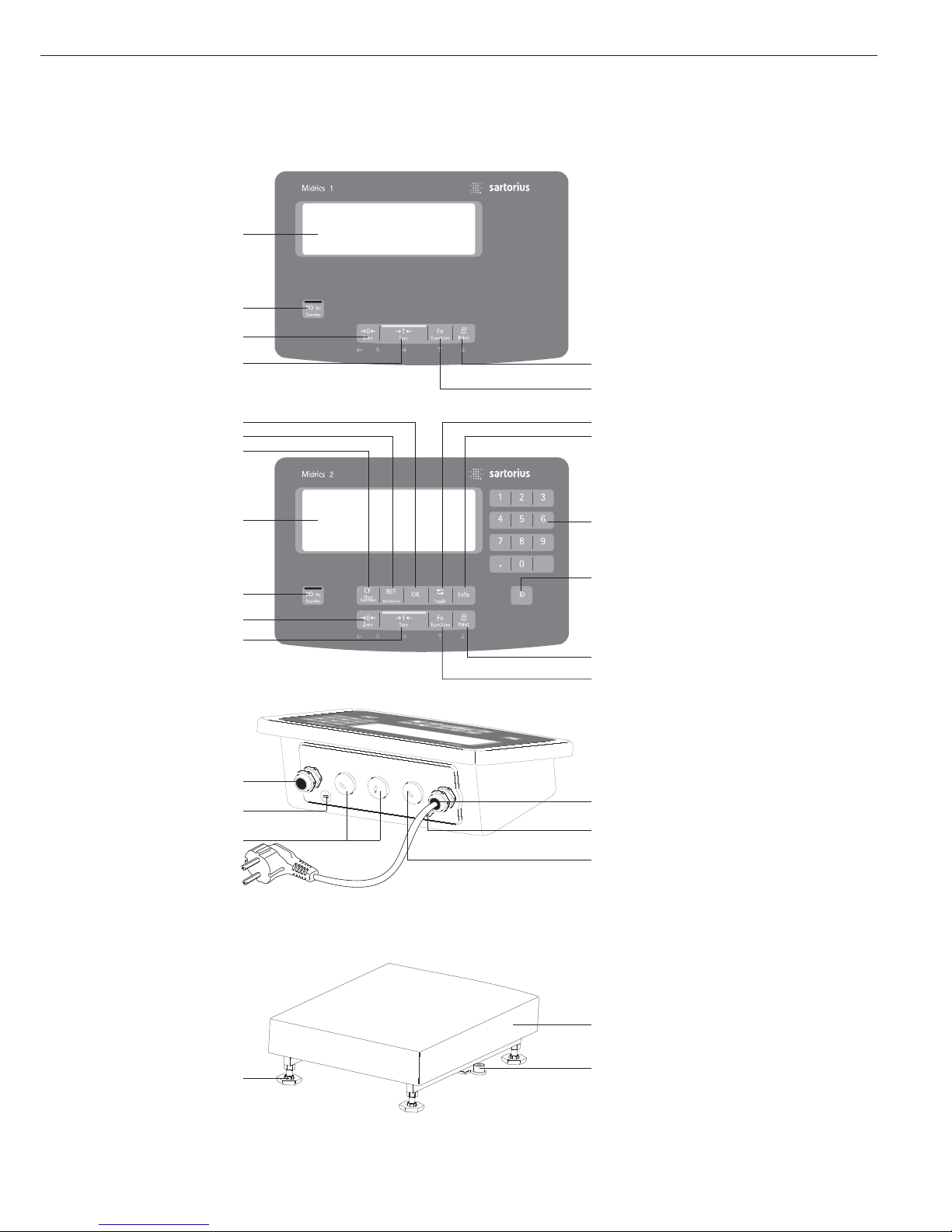
Display and Keypad
1 Display
(for details, see the chapter entitled
“Operating Design")
2 On/standby key
3 Zero key
4 Tare key
5 Function key (e.g., toggle between
gross and net values)
6 Print key (data output)
7 ID key
(for entering product information)
8 Numeric keypad
9 Info key (for viewing ID codes
and manual tare values)
10 Toggle key
(function depends on application)
11 OK key
(function depends on application)
12 Reference value key
(function depends on application)
13 Clear-function key
(function depends on application)
Back Panel of Display and Control Unit
14 Connector for weighing platform
15 Menu access switch
16 Optional:
Second interface (UniCOM)
17 Optional:
RS-232C interface (COM1)
18 Ground terminal
(equipotential bonding)
19 Power cord
Weighing Platform
20 Load plate
21 Level indicator (verified models only)
22 Leveling feet
General View of the Equipment
7
6
5
10
9
14
8
7
11
12
13
1
2
3
4
Midrics 1
Midrics 2
Midrics
display and
control unit
Midrics
weighing platform
19
18
17
14
15
16
21
20
22
6
5
1
2
3
4

Keys
Operation of the Midrics
®
1 or Midrics
®
2 scale involves just a few keys.
These keys have one function during
measurement and another during
configuration. Some of the keys have
one function when pressed briefly
and another activated by pressing
and holding the key for longer than
2 seconds.
If a key is inactive, this is indicated
as follows when it is pressed:
– The error code “———-” is displayed
for 2 seconds. The display then returns
to the previous screen content.
Configure the operating menu for
the desired application program first
(printer settings, etc.). Then you can
begin weighing.
Input
Keypad Input
Labeled Keys
Some keys have a second function,
activated by pressing and holding
the key for at least 2 seconds.
Whether a function is available
depends on the operating state
and menu settings.
e On/standby
(in standby mode,
OFF is displayed).
( – Zero the scale
– Cancel calibration/adjustment
) – Tare the scale
k Toggle between 1
st
and 2ndweight
unit, or gross and net values,
or normal and 10-fold higher
resolution, depending on operating
menu settings
p – To print: press briefly
(< two seconds).
Midrics 2 only:
d ID key for entering product
information
Midrics 2 only:
I View application data or manual
tare values, depending on the key
pressed subsequently (e.g., ))
Midrics 2 only:
w Toggle between display modes
within an application program
Midrics 2 only:
O Save a value or start an application
program.
Midrics 2 only:
r Modify a reference value
Midrics 2 only:
c – Quit an application or delete
an input character
Midrics 2 only:
0, 1, 2 … 9
Enter numbers, letters and other
characters
Operating Design
8
Operating elements: Midrics®2

Numeric Input Through the Keypad
(Midrics 2 only)
§ To enter numbers (one digit at a time):
Press 0, 1, 2 …9
§ To save input:
press the required key (e.g., )
to save manual tare input)
§ To delete a digit:
Press c
Loading a Tare Value from
the Weighing Platform
You can store the weight on
the weighing platform; for example,
as a tare weight, by pressing
the ) key
Input Through the
Digital Input Port
You can connect a remote hand switch
or foot switch to the input control line,
for use with all application programs.
Assign one of the following functions
to this switch in the operating menu,
under “
Control IO/ -> Control
input":
CTRL IO
CTRL INP
8
8.4 Universal IN
…
…
…
CTRL OUT
For a detailed list of menu items, please see
the chapter entitled “Configuration."
9

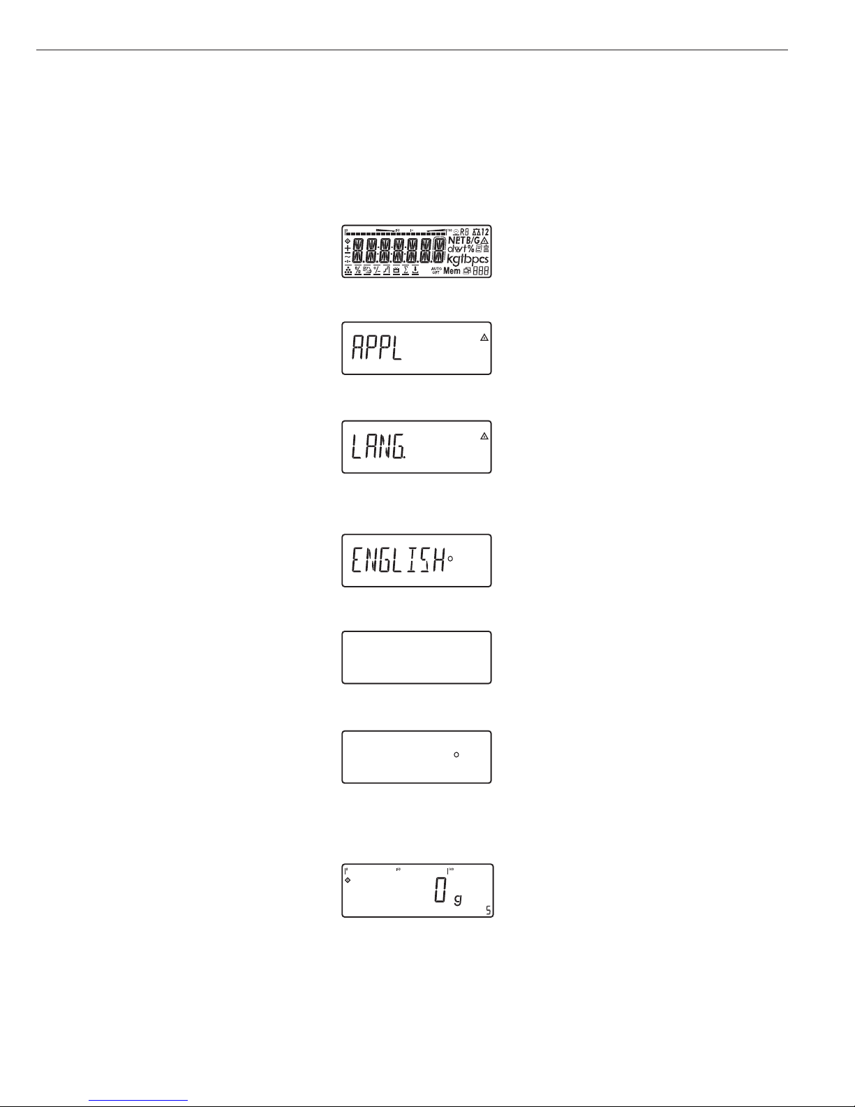
Display in Weighing Mode
The illustration above shows all display
segments and the symbols and other
elements used during normal weighing
operation.
1. Bar graph
– Shows the percentage of the
weighing platform's capacity that
is “used up" by the load on the
scale (gross value), or
– Shows the measured value in
relation to a target value
(with the Checkweighing or
Classification application)
2. Printing in progress
3. Display of the range on multiple-range
instruments
4. Indicates a net or gross value in
the main display (when data is stored
in tare memory)
5. Identifies the value on the main
display as calculated (value not valid
in legal metrology)
6. Battery symbol showing status of
rechargeable battery (empty outline
indicates battery is drained)
7. GMP-compliant printing in progress
(optional; with interface and “clock"
options)
8. Weight unit of the value displayed
9. Numeric display; e.g., showing
reference value (Midrics 2 only)
Midrics 2:
10. Symbol indicating data transfer:
– Interface initialized
– Flashes during data transfer
11. Symbols for reference updating
(Midrics 2 only)
– Auto: Depending on the weight
value, a reaction is triggered
in the application
– Opt: Automatic reference
updating has been performed
(Counting application)
12. Weight value or calculated value
(main display)
13. Application symbols for Midrics 2
applications:
A Counting
B Weighing in Percent
V Averaging (Animal Weighing)
H Checkweighing
W Classification
L Totalizing
R Net-total Formulation
Checkweighing:
Batching to a target value
Verified models only:
14. The “zero-setting" symbol is displayed
after the active scale or weighing
platform has been zeroed
15. Stability symbol
16. Plus or minus sign for the value
displayed
17. Busy symbol; indicates that an internal
process is in progress
There are two display modes:
– Normal operation (weighing mode)
– Operating menu (for configuration)
Weighing Mode: Display
of Measured and Calculated
Values (Main Display)
Application, printing and battery
symbols:
The application symbol indicates
the selected program; for example:
A Counting application symbol
S Printing mode active
T GMP printing mode active
The battery symbol b indicates
the charge level of the external
rechargeable battery.
Operating Design
10
13
4
5
6
7
8
9
1011
12
13
14
16
15
17
2

Bar graph
The bar graph shows the percentage of the
weighing platform's capacity that is “used
up" by the load on the scale (gross value).
0% Lower limit
100% Upper limit
The following symbols indicate tolerance
levels for Checkweighing:
Bar graph with 10% markings
Minimum in Checkweighing
Target in Checkweighing
Maximum
Plus/minus sign:
+ or - for weight value or calculated
value,
o when the weighing platform
is zeroed or tared.
Measured value/result line
This field shows weight values and
calculated values (alphanumeric characters)
Unit and stability
When the weighing system reaches
stability, the weight unit or the unit for
a calculated value is displayed here.
Tare in memory, calculated values:
The following symbols may be displayed
here:
a Calculated value (not valid in
legal-for-trade applications)
NET Net value
(gross weight minus tare)
B/G Gross value
(net value plus tare)
Data in tare memory, calculated values,
designation of the active weighing
platform
pt Identification of manual tare
input when viewing tare
information
Saving Data in Weighing Mode
All of the application parameters
saved (e.g., reference values) remain in
memory and are still available after
– the Midrics has been switched off
and back on again, or
– you return to the originally selected
application from a second one (e.g.,
when you switch from Averaging back
to Counting, all parameters saved
for Counting are available)
11

Operating Menu Navigation
The keys below the readout let you
navigate the menu and define parameters
for configuration.
Opening the Menu
Press the e key to switch the Midrics
off and then on again; while all segments
are displayed, press the ) key briefly.
Navigating the Menu
( Close the active submenu and
return to the next higher menu level
(“back")
) – Press briefly:
Select and save a menu item
– Press and hold (> 2 seconds):
Exit the menu
k Show the next item on the same
menu level (the display scrolls
through all items in series)
p Print the menu settings starting
from the current position, or print
Info data
Alphanumeric Input in the Menu
( – Press briefly:
Activate character to the left
of the current character
(when first character is active:
exit input mode without saving
changes)
– Press and hold (> 2 seconds):
Exit input mode without saving
changes
) – Press briefly:
Confirm currently active character
and move cursor 1 position to
the right (after the last character:
save input)
– Press and hold (> 2 sec ):
Save current input and display
the menu item
k – Cursor in first position,
no characters entered yet:
Delete character(s) and enter 0
– Change the displayed character;
scroll forward (sequence:
0 through 9, decimal point,
minus sign, A to Z, space)
p – Cursor in first position,
no characters entered yet: Delete
entire string and enter a space
– Change the displayed character;
scroll backwards (sequence:
space, Z to A, minus sign, decimal
point, 9 through 0)
Numeric input in Midrics 2 operating
menu:
Enter values (date and time, etc.) using
the 10-key numeric keypad
Display of Menu Settings
The illustrations above show examples
of the main display during menu
configuration.
1 Selected menu item on the text
level (e.g. printer, for configuring
the connected printer)
2 Menu history (indicates the highest
menu level)
3 Indication that there are other
submenus
4 Highest level in numeric menu
5 Second level in numeric menu
6 Third level in numeric menu
Errors
– If a key is inactive, “-------" or
“No function" is displayed briefly
(2 seconds)
– Temporary errors are displayed for
2 seconds in the measured value/result
line (e.g.,
Inf 09); fatal errors are
displayed steadily (e.g.,
Err 101) until
the Midrics is reset (switched off and
then on again).
For a detailed description,
see “Error Codes" on page 89.
Data Output
Printer
You can connect two strip or label
printers to the Midrics 1 or Midrics 2
and have printouts generated at the
press of a key or automatically. You can
also configure separate summarized
printouts, and print a list of the active
menu settings. See “Configuring
Printouts" on page 82 for details.
Backup
Application parameters (such as
reference values) are saved when you
change application programs or switch
off the Midrics. You can assign a password to prevent unauthorized users
from changing settings in the “Device
parameters" menu under:
Setup
Password
See also pages 14 and 31.
Operating Design
12
Display of menu settings: Text menu (example) Display of menu settings: Numeric menu (example)
You can configure the Midrics scale
by selecting parameters in the operating
menu. The parameters are combined
in the following groups (this is the
highest menu level):
– Application parameters
– Fn key function
– Device parameters (“
Setup")
– Device-specific information (“
Info")
– Language
When the scale is used in legal
metrology, not all parameters can
be accessed.
Factory-set parameters are identified
by an asterisk (“*") in the list starting
on page 16.
You can choose from six language
settings for the display of information:
– German
– English (factory setting)
– English with U.S. date/time format
– French
– Italian
– Spanish
Printing parameter settings:
§ Open the operating menu and
press the p key
Scope of printout:
Depends on the active menu level
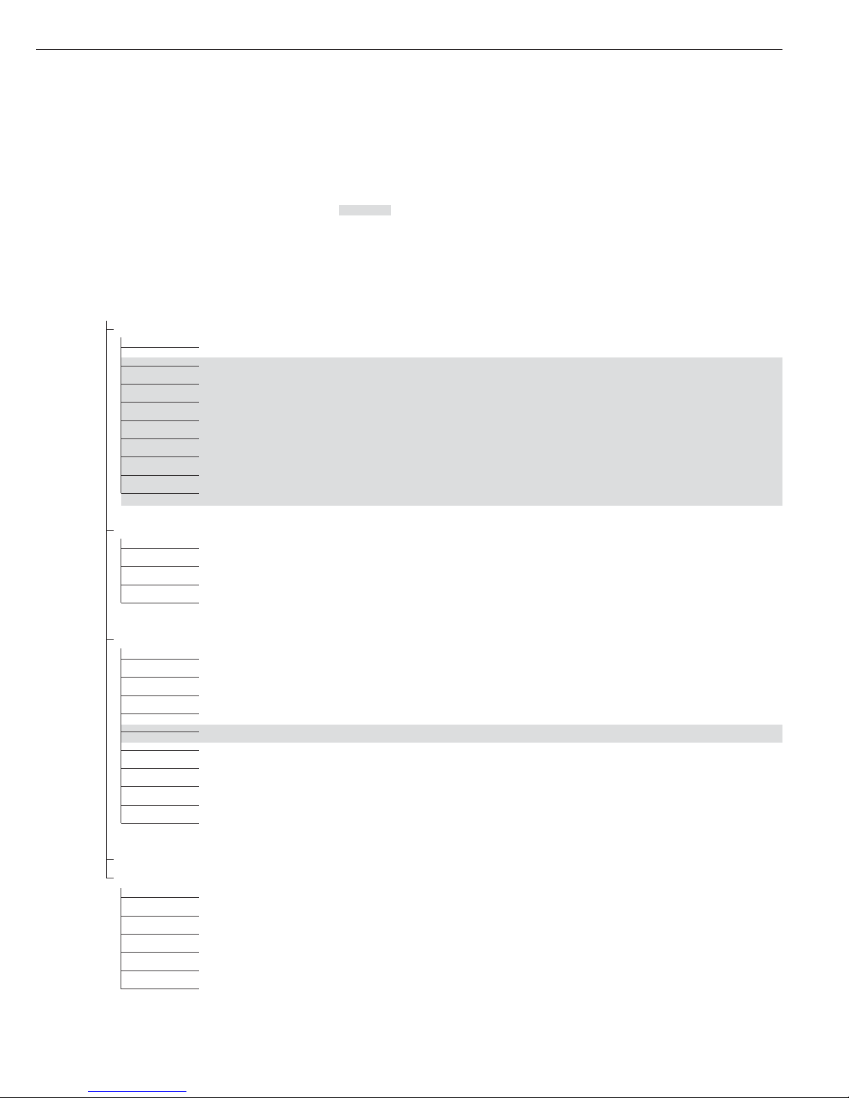
Setting the Language
Setting the Language
Example: Selecting “U.S. Mode" for the language
e
Switch on the scale
)
While all segments are lit,
press the ) key
The first item in the main menu is shown:
APPL
k
Switch to the LANG. menu item
(press k repeatedly until
LANG.
is shown)
)
Select LANG. to open the submenu
for setting the language
The currently active language setting
is shown
k
Press k repeatedly until U.S. Mode
is displayed
)
Confirm this menu item
(
Exit this menu level and configure
other settings as desired, or
)
(press and hold) Exit the operating menu
Configuration
13
U.S. Mode
U.S. Mode

Entering or Changing the Password
Example:
Assign a password (in this example,
AB2) to protect the application program settings APPL
and the device parameters SETUP from unauthorized changes
e
1. Switch on the scale
)
2. While all segments are lit,
press the ) key
The first item in the main
menu is shown:
APPL
k
3. Select the SETUP menu item
(press k repeatedly until
SETUP is displayed)
)
4. Open the SETUP menu
k
5. Select the PASSWORD menu
item (press k repeatedly
until
PASSWORD is displayed)
)
6. Open the PASSWORD menu
p, p
7. Enter the first character
using the p and k keys
(in this example:
A)
)
8. Save the character
p, p, p
9. Enter the second character
using the p and k keys
(in this example:
B)
)
10. Save the character
k, k, k
, 11. Enter the third character
using the p and k keys
(in this example:
2)
)
12. Save the password
(
13. Exit this menu level
to configure other menu
settings, or
)
14. Exit the operating menu
(press and hold the ) key)
To modify or delete a password:
Overwrite the old password
with the new password, or enter
a space as the password and
press ) to confirm
14
1stlevel 2ndlevel Function
display display
Menu
appl Select and configure application programs
W Basic weighing function
Z Counting
Z nm_ Neutral Measurement
V Averaging (animal weighing)
O Checkweighing
W Classification
L Weighing in percent
R Net-total formulation
L Totalizing
Fn-Key Define the function of the k key
off No function
gro net Gross/net toggling
2.unit Toggle between weight units
res 10 10-fold increased resolution
Setup Adapt Midrics to user requirements
wp1 Settings for weighing instrument on WP1
com1 Settings for the RS-232 interface
UNICOM Settings for the optional second interface
ctrl 10 Assign a function to the control inputs/outputs
barcode Set the bar code scanner function
prtprot Configure the printout
Utilit Operating parameters
time Set the time
Date Set the date
password Enter a password to protect menu settings
Info View device-specific information (service date, serial number, etc.)
Lang Select language for calibration, adjustment and GMP printouts
deutsch German
english English
u.s. mode English with U.S. date/time format
franc. French
ital. Italian
espanol Spanish
Operating Menu Overview
You can configure the Midrics to meet
individual requirements by entering
user data and setting selected parameters
in the operating menu.
Menu levels are identified by texts, and numeric codes identify the individual settings.
= Setting/function available on Midrics 2 only
15
Operating Menu
= Setting/function available on Midrics 2 only
* Factory setting
Menu
appl Application Programs
W
Basic weighing function
3.5. Minimum load for automatic taring and automatic printing
3.5.1* 1 digit
3.5.2 2 digits
3.5.3 5 digits
3.5.4 10 digits
3.5.5 20 digits
3.5.6 50 digits
3.5.7 100 digits
3.5.8 200 digits
3.5.9 500 digits
3.5.10 1000 digits
3.7. Automatic taring: first weight tared
3.7.1* Off
3.7.2 On
9.1. Factory settings for all application programs
9.1.1 Yes
9.1.2* No
Z Counting
3.5. Minimum load for automatic taring and automatic printing
Numeric menu as for Weighing
3.6. Minimum load for initialization
3.6.1* 1 digit
3.6.2 2 digits
3.6.3 5 digits
3.6.4 10 digits
3.6.5 20 digits
3.6.6 50 digits
3.6.7 100 digits
3.6.8 200 digits
3.6.9 500 digits
3.6.10 1000 digits
3.7. Automatic taring: first weight tared
3.7.1* Off
3.7.2 On
3.8. Start application and load most recent application data when the Midrics is switched on
3.8.1 Automatic (on)
3.8.2* Manual (off)
3.9. Resolution for calculation of reference value
3.9.1* Display resolution
3.9.2 Display resolution + 1 decimal place
3.9.3 Display resolution + 2 decimal places
3.9.4 Internal resolution
3.11. Parameter for saving weight values (“storage parameter")
3.11.1* At stability
3.11.2 At increased stability
3.12. Reference sample updating (“APW update")
3.12.1 Off
3.12.3* Automatic
9.1. Factory settings for all application programs
9.1.1 Yes
9.1.2* No
16

appl
Z nm
Neutral Measurement
3.5. Minimum load for automatic taring and automatic printing
Numeric menu as for Weighing
3.6. Minimum load for initialization
Numeric menu as for Counting
3.7. Automatic taring: first weight tared
3.7.1* Off
3.7.2 On
3.8. Start application and load most recent application data when the Midrics is switched on
3.8.1 Automatic (on)
3.8.2* Manual (off)
3.9. Resolution for calculation of reference value
3.9.1* Display resolution
3.9.2 Display resolution + 1 decimal place
3.9.3 Display resolution + 2 decimal places
3.9.4 Internal resolution
3.10. Decimal places in displayed result
3.10.1* None
3.10.2 1 decimal place
3.10.3 2 decimal places
3.10.4 3 decimal places
3.11. Parameter for saving weight values
3.11.1* At stability
3.11.2 At increased stability
9.1. Factory settings for all application programs
9.1.1 Yes
9.1.2* No
V Averaging (Animal Weighing)
3.5. Minimum load for automatic taring and automatic printing
Numeric menu as for Weighing
3.6. Minimum load for automatic start
Numeric menu as for Counting
3.7. Automatic taring: first weight tared
3.7.1* Off
3.7.2 On
3.8. Start application and load most recent application data when the Midrics is switched on
3.8.1 Automatic (on)
3.8.2* Manual (off)
3.18. Start of averaging routine
3.18.1* Manual
3.18.2 Automatic
3.19. Animal activity
3.19.1 0.1% of the animal/object
3.19.2* 0.2% of the animal/object
3.19.3 0.5% of the animal/object
3.19.4 1% of the animal/object
3.19.5 2% of the animal/object
3.19.6 5% of the animal/object
3.19.7 10% of the animal/object
3.19.8 20% of the animal/object
3.19.9 50% of the animal/object
3.19.10 100 % of the animal/object
3.20. Automatic printout of results
3.20.1* Off
3.20.2 On
17
appl
V
Averaging (Animal Weighing)
3.21. Static display of result after load removed
3.21.1* Display is static until unload threshold reached
3.21.2 Display is static until c is pressed
9.1. Factory settings for all application programs
9.1.1 Yes
9.1.2* No
O Checkweighing
3.5. Minimum load for automatic taring and automatic printing
Numeric menu as for Weighing
3.6. Minimum load for initialization
Numeric menu as for Counting
3.7. Automatic taring: first weight tared
3.7.1* Off
3.7.2 On
3.8. Start application and load most recent application data when the Midrics is switched on
3.8.1 Automatic (on)
3.8.2* Manual (off)
4.2. Checkweighing range
4.2.1* 30 to 170%
4.2.2 10% to infinity
4.3. Activate control line for “Set” as:
4.3.1* “Set” output
4.3.2 Ready to operate (for process control systems)
4.4. Activation of outputs
4.4.1 Off
4.4.2 Always active
4.4.3 Active at stability
4.4.4* Active within checkweighing range
4.4.5 Active at stability within the checkweighing range
4.5. Parameter input
4.5.1* Min, max, target
4.5.2 Only target with percent limits
4.6. Automatic printing
4.6.1* Off
4.6.2 On
4.6.3 Only values within tolerance
4.6.4 Only values outside tolerance
4.7. Checkweighing toward zero
4.7.1* Off
4.7.2 On
4.7.3 On
9.1. Factory settings for all application programs
9.1.1 Yes
9.1.2* No
W Classification
3.5. Minimum load for automatic taring and automatic printing
Numeric menu as for Weighing
3.6. Minimum load for initialization
Numeric menu as for Counting
3.7. Automatic taring: first weight tared
3.7.1* Off
3.7.2 On
18

appl
W Classification
3.8. Start application and load most recent application data when the Midrics is switched on
3.8.1 Automatic (on)
3.8.2* Manual (off)
4.3. Activate control line for “Set” as:
4.3.1* “Set” output
4.3.2 Ready to operate (for process control systems)
4.7. Activation of outputs
4.7.1 Off
4.7.2 Always active
4.7.3* Active at stability
4.8. Number of classes
4.8.1* 3 classes
4.8.2 5 classes
4.9. Parameter input
4.9.1* Weight values
4.9.2 Percentage
4.10. Automatic printing
4.10.1* Off
4.10.2 On
9.1. Factory settings for all application programs
9.1.1 Yes
9.1.2* No
L Weighing in Percent
3.5. Minimum load for automatic taring and automatic printing
Numeric menu as for Weighing
3.6. Minimum load for initialization
Numeric menu as for Counting
3.7. Automatic taring: first weight tared
3.7.1* Off
3.7.2 On
3.8. Start application and load most recent application data when the Midrics is switched on
3.8.1 Automatic (on)
3.8.2* Manual (off)
3.9. Resolution for calculation of reference value
3.9.1* Display resolution
3.9.2 Display resolution + 1 decimal place
3.9.3 Display resolution + 2 decimal places
3.9.4 Internal resolution
3.10. Decimal places in displayed result
3.10.1* None
3.10.2 1 decimal place
3.10.3 2 decimal places
3.10.4 3 decimal places
3.11. Parameter for saving weight values
3.11.1* At stability
3.11.2 At increased stability
3.15. Display
3.15.1* Residue
3.15.2 Loss
9.1. Factory settings for all application programs
9.1.1 Yes
9.1.2* No
19

appl
R
Net-total Formulation (2ndTare Memory)
3.5. Minimum load for automatic taring and automatic printing
Numeric menu as for Weighing
3.6. Minimum load for automatically saving/transferring values
Numeric menu as for Counting
3.7. Automatic taring: first weight tared
3.7.1* Off
3.7.2 On
3.17. Printout when value is saved in totalizing memory
3.17.1 Automatic printout of results off
3.17.2* Generate printout with complete standard configuration each time O is pressed
3.17.3 Generate printout with complete standard configuration only the first time O is pressed
9.1. Factory settings for all application programs
9.1.1 Yes
9.1.2* No
L Totalizing
3.5. Minimum load for automatic taring and automatic printing
Numeric menu as for Weighing
3.6. Minimum load for automatically saving/transferring values
Numeric menu as for Counting
3.7. Automatic taring: first weight tared
3.7.1* Off
3.7.2 On
3.8. Start application and load most recent application data when the Midrics is switched on
3.8.1 Automatic (on)
3.8.2* Manual (off)
3.16. Values saved automatically
3.16.1* Off
3.16.2 On
3.17. Individual component data printed when value is added to totalizing memory
3.17.1 Automatic printout of results off
3.17.2* Individual printout of a totalizing item when O is pressed
3.17.3 Components of transaction printed when O is pressed
9.1. Factory settings for all application programs
9.1.1 Yes
9.1.2* No
off Disabled
fn-key k Key Assignment
off * No k key function
gro net Gross/net toggling
2. unit Show 2ndWeight unit
res 10 10-fold increased resolution Display: max. 5 seconds
20
Setup Device Parameters
Password prompt displayed if a password is configured
wp-1
1
Weighing platform 1
(Display designation of this menu level: 1)
1.1. Adapt weighing instrument to ambient conditions (adapt filter)
1.1.1 Very stable conditions
1.1.2* Stable conditions
1.1.3 Unstable conditions
1.1.4 Very unstable conditions
1.2. Application filter
1.2.1* Final readout
1.2.2 Filling mode
1.2.3 Low filtering
1.2.4 Without filtering
1.3. Stability range
1.3.1 4 digit
1.3.2 1 digit
1.3.3 1 digit
1)
1.3.4* 2 digits
1)
1.3.5 4 digits
1)
1.3.6 8 digits
1)
1.4. Stability symbol delay
1.4.1 No delay
1.4.2* Short delay
1.4.3 Average delay
1.4.4 Long delay
1.5. Taring
1)
1.5.1 Without stability
1.5.2* After stability
1.6. Auto zero
1.6.1* On
1.6.2 Off
1.7. Weight Unit 1
2)
1.7.1 Grams / o
1.7.2 Grams / g
1.7.3 Kilograms / kg
1.7.4 Carats / ct
1)
1.7.5 Pounds / lb
1)
1.7.6 Ounces / oz
1)
1.7.7 Troy ounces / ozt
1)
1.7.8 Hong Kong taels / tlh
1)
1.7.9 Singapore taels / tls
1)
1.7.10 Taiwanese taels / tlt
1)
1.7.11 Grains /GN
1)
1.7.12 Pennyweights / dwt
1)
1.7.14 Parts per pound / lb
1)
1.7.15 Chinese taels / tlc
1)
1.7.16 Mommes / mom
1)
1.7.17 Austrian carats / k
1)
1.7.18 Tola / tol
1)
1.7.19 Baht / bat
1)
1.7.20 Mesghal / MS
1)
1.7.21 Tons / t
1.7.22 Pounds: ounces
1)
1.8. Display accuracy 1
1)
1.8.1* All digits
1.8.2 Reduced by 1 decimal place for load change
1.8.14 10-fold increased resolution
1.8.15 Resolution increased by 2 scale intervals (e.g., 5 g to 1 g)
1.8.16 Resolution increased by 1 scale interval
(e.g., from 2 g to 1 g or from 10 g to 5 g)
1)
Not available on instruments verified for use in legal metrology
2)
Depends on weighing platform model
21

Setup
wp-1
1
1.9. Calibration and adjustment
1.9.1* External calibration/adjustment; default weight
1.9.3 External calibration/adjustment; weight can be selected under menu item 1.18.1
1.9.10 No function when you press and hold ) > 2 sec
1.10. Calibration/adjustment sequence
1.10.1 Calibration with automatic adjustment
1.10.2* Calibration with adjustment triggered manually
1.11. Zero-setting range
1.11.1 1 percent/max. cap.
1.11.2* 2 percent/max.cap.
1.12. Initial zero-setting range
1.12.2 2 percent/max. cap.
1.12.3 5 percent/max.cap. (setting depends on model)
1.12.4* 10 percent/max.cap.
1.13. Tare/zero at power on
1.13.1* On
1.13.2 Off, load previous tare value
1.13.3 Only zero at power on
1.15. Calibration prompt
1.15.1* Off
1.15.2 Calibration prompt (W) flashes on the display
1.16. External calibration/adjustment
1)
1.16.1* Accessible
1.16.2
2)
Blocked
1.17. Calibration weight unit
1.17.1 Grams
1.17.2* Kilograms
1.17.3 Tons
1.17.4 Pounds
1)
1.18. Enter calibration weight
1.18.1 External user-defined weight (enter value; e.g.: 10,000 kg)
3.1. Weight unit 2
3)
3.1.1 Grams / o
3.1.2 Grams / g
3.1.3* Kilograms / kg
3.1.4 Carats /ct
1)
3.1.5 Pounds /lb
1)
3.1.6 Ounces /oz
1)
3.1.7 Troy ounces / ozt
1)
3.1.8 Hong Kong taels / tlh
1)
3.1.9 Singapore taels / tls
1)
3.1.10 Taiwanese taels / tlt
1)
3.1.11 Grains / GN
1)
3.1.12 Pennyweights / dwt
1)
3.1.14 Parts per pound / lb
1)
3.1.15 Chinese taels / tlc
1)
3.1.16 Mommes / mom
1)
3.1.17 Austrian carats /k
1)
3.1.18 Tola / tol
1)
3.1.19 Baht / bat
1)
3.1.20 Mesghal / MS
1)
3.1.21 Tons / t
3.1.22 Pounds:ounces
1)
3.2. Display accuracy 2
1)
3.2.1* All digits
3.2.2 Reduced by 1 decimal place for load change
3.2.14 10-fold increased resolution
3.2.15 Resolution increased by 2 scale intervals (e.g., 5 g to 1 g)
3.2.16 Resolution increased by 1 scale interval (e.g., 2 g to 1 g or from 10 g to 5 g)
3.3. Weight unit 3
3)
(settings as for 3.1, “Weight unit 2”)
3.4. Display accuracy
3)
(settings as for 3.2, “Display accuracy 2”)
9.1. Restore factory settings in WP1 numeric menu
9.1.1 Yes
9.1.2* No
1)
= Not available on instruments verified for use in legal metrology
2)
= Factory setting on instrument verified for use in legal metrology
3)
= Menu depends on weighing platform model
22
Setup
Com1
2
Interface port 1 (optional)
(Display designation of this menu level: 2)
off
*
Off
datProt Data protocol
sbi
*
SBI: standard version
5.1. Baud rate
5.1.1 150 baud
5.1.2 300 baud
5.1.3 600 baud
5.1.4* 1200 baud
5.1.5 2400 baud
5.1.6 4800 baud
5.1.7 9600 baud
5.1.8 19,200 baud
5.2. Parity
5.2.2 Space
2)
5.2.3 Odd
5.2.4 Even
5.2.5 None
3)
5.3. Number of stop bits
5.3.1* 1 stop bit
5.3.2 2 stop bits
5.4. Handshake mode
5.4.1 Software handshake
5.4.3* Hardware handshake, 1 character after CTS
5.6. Number of data bits
5.6.1* 7 data bits
5.6.2 8 data bits
6.1. Data output: manual/automatic
6.1.1 Manual without stability
6.1.2* Manual after stability
6.1.4 Automatic without stability
6.1.5 Automatic with stability
6.1.7 Protocol for computer (PC)
6.3. Time-dependent automatic data output
6.3.1* 1 display update
6.3.2 2 display updates
6.3.4 10 display updates
6.3.7 100 display updates
7.2. Data output: line format for printout
7.2.1 For raw data: 16 characters
7.2.2* For other applications: 22 characters
9.1. Restore factory settings in numeric menu COM1: SBI
9.1.1 Yes
9.1.2* No
xbpi-232 XBPI-232
1)
Menu depends on weighing platform model
2)
not with setting 5.6.2 (8 bits)
3)
not with setting 5.6.1 (7 bits)
23

Setup
Com1
2
datProt
SMA SMA interface function
5.1. Baud rate
5.1.1 150 baud
5.1.2 300 baud
5.1.3 600 baud
5.1.4 1200 baud
5.1.5 2400 baud
5.1.6 4800 baud
5.1.7* 9600 baud
5.1.8 19,200 baud
5.2. through 5.6.
Numeric menu as for SBI
Printer Printer configuration
YDP01IS YDP01IS
line
*
Strip printer
label Label printer
lab ff Label printer with manual feed
YDP02 YDP02 variants
5.1. Baud rate
5.1.4* 1200 baud
5.1.5 2400 baud
5.1.6 4800 baud
5.1.7 9600 baud
5.2. Parity
5.2.2 Space
5.2.3* Odd
5.2.4 Even
5.3. Number of stop bits
5.2.2 Space
5.3.1* 1 stop bit
5.3.2 2 stop bits
5.4. Handshake mode
5.4.1 Software handshake
5.4.3* Hardware handshake, 1 character after CTS
YDP03 YDP03-0CE
5.1. Baud rate
5.1.4* 1200 baud
5.1.5 2400 baud
5.1.6 4800 baud
5.1.7 9600 baud
5.1.8 19,200 baud
5.2. through 5.4.
Numeric menu as for COM02
YDP02IS YDP02IS
line
*
Strip printer
label Label printer
24
Setup
Com1
2
Printer
Uni-pri Universal interface
5.1. Baud rate
5.1.1 150 baud
5.1.2 300 baud
5.1.3 600 baud
5.1.4 1200 baud
5.1.5 2400 baud
5.1.6 4800 baud
5.1.7* 9600 baud
5.1.8 19,200 baud
5.2. Parity
5.2.2 Space
1)
5.2.3 Odd
5.2.4 Even
5.2.5* None
2)
5.3. Number of stop bits
5.3.1* 1 stop bit
5.3.2 2 stop bits
5.4. Handshake mode
5.4.1* Software handshake
5.4.3 Hardware handshake, 1 character after CTS
5.6. Number of data bits
5.6.1 7 data bits
5.6.2* 8 data bits
YDP04IS
*
YDP04IS
line
*
Strip printer
label Label printer
lab ff Label printer with manual feed
yam01is YAM01IS as electronic memory for print data
Memory Verifiable data memory
yam01is YAM01IS external data memory
Off Disabled
1)
not with setting 5.6.2 (8 bit)
2)
not with setting 5.6.1 (7 bits)
25

Setup
unicom
3
Interface port 2 (Optional)
(Display designation of this menu level: 3)
off
*
Off
datprot Data protocol
sbi
*
SBI: standard version
5.1. through 9.1.
Numeric menu as for COM1
bpi-232 XBPI-232
bpi-485 XBPI-485
0 to 31 Network address: From 0 to 31 inclusive
sma SMA interface function
5.1. through 5.6.
Numeric menu as for COM1
ETHER
src-ip Source IP: 192.168.0.1*
src.name Source name (16 characters maximum)
lis.port Listen on port: 49155*
supnet Subnet mask:255.255.255.0*
gate-ip Gateway IP: 0.0.0.0*
dest-ip Destination IP: 0.0.0.0*
dest.por Destination port: 49155*
Protocol TCP*
UDP
Mode SBI (server)* 6.1. Manual output/automatic
6.1.1 Manual without stability
6.1.2 * Manual after stability
6.1.4 Automatic without stability
6.1.5 Automatic with stability
6.1.7 Data record for computer printout
7.2. Data output: line format for printout
7.2.1 For raw data: 16 characters
7.2.2* For other apps.: 22 characters
SBI-C/S (client) 6.1. Manual output/automatic
6.1.1 Manual without stability
6.1.2 * Manual after stability
6.1.4 Automatic without stability
6.1.5 Automatic with stability
6.1.7 Data record for computer printout
XBPI 6.3. Time-dependent automatic
data output
SMA 6.3.1 * 1 display update
Modbus/TCP 6.3.2 2 2 display updates
6.3.4 10 10 display updates
6.3.7 100 100 display updates
7.2. Data output: line format for printout
7.2.1 For raw data: 16 characters
7.2.2* For other apps.: 22 characters
26

Setup
uniCom1
3
Second interface (optional)
Printer Printer configuration
YDP01IS YDP01IS
line
*
Strip printer
label Label printer
lab ff Label printer with manual feed
YDP02 YDP02
5.1. through 5.4.
Numeric menu as for COM1
YDP03 YDP03-0CE
5.1. through 5.4.
Numeric menu as for COM1
YDP02IS YDP02IS
line
*
Strip printer
label Label printer
Uni-pri Universal interface
5.1. through 5.6.
Numeric menu as for COM1
YDP04IS
*
YDP04IS
line
*
Strip printer
label Label printer
lab ff Label printer with manual feed
yam01is YAM01IS as electronic memory for print data
Analog Analog data output port for PLC operation
8.12. Analog output: value
8.12.1* Net value
8.12.2 Gross value
8.13. Analog output: error indicator
8.13.1* High level (20 mA)
8.13.2 Low level (0/4 mA). When menu is open or during calibration:
0/4 mA on this interface.
8.14. Analog output: mode
8.14.1*
1)
Zero to maximum capacity
8.14.2 Minimum/maximum values
8.15. Analog output: min./max.
8.15.1
2)
Min. (0/4 mA) input in kg
8.15.2 Max. (20 mA) input in kg
Memory Verifiable data memory
yam01is YAM01IS external data memory
1)
When setting 8.14.1 is active, analog data output only works for XBPI weighing instruments
2)
not with setting 8.14.1
27
 Loading...