

Page 1
Operating Instructions
Sartorius Midrics®1| Midrics®2
Models MW1 | MW2
Complete Scales
98648-014-94
Page 2

Midrics®1 and 2 are rugged complete
scales for the demanding area of daily
quality control. They meet the highest
requirements placed on the accuracy
and reliability of weighing results:
– in the food industry
– in the pharmaceutical industry
– in the chemical industry
– in the electronics and metal-working
industries
Midrics
®
complete scales are:
– Rugged and durable
(stainless steel housing)
– Easy to clean and disinfect
– Easy to operate, thanks to:
– large, backlit display segments
– large keys with positive click action
– Independent of the weighing platform
location
– Equipped with a range of interfaces
for flexible use
– Password-protected from unauthorized
changes in the operating menu
Additional characteristics (Midrics
®
2):
– Input functions for tare values
through numeric keypad
– Option for 4 alphanumeric lines
to identify samples
– Fast response times
– Designation of weight values with up
to 4 lines of alphanumeric text
– Built-in application programs for:
– Counting
– Neutral measurement
– Weighing in percent
– Averaging
– Checkweighing
– Classification
– Net-total formulation
– Totalizing
– Automatic initialization when the
Midrics is switched on
– Automatic taring when the first load
is placed on the weighing platform
– Optional remote control using an
external computer
Symbols
The following symbols are used
in these instructions:
§ denotes general operating instructions
$ indicates instructions for exceptional
cases
> describes the outcome of an
operating step
!indicates a hazard
Intended Use
2
Page 3

2 Intended Use
4 Warnings and Safety Precautions
4 Getting Started
4 Unpacking the Midrics
4 Equipment Supplied
4 Installation
4 Conditioning the Scale
5 Connecting the Scale to AC Power
6 Leveling the Weighing Platform
6 Operating Limits
7 General View of the Equipment
7 Display and Keypad
7 Back Panel
7 Weighing Platform
8 Operating Design
8 Keypad
8 Keypad Input
9 Input Through the Digital
Control Port
10 Measured Value Display
10 Display of Measured and
Calculated Values
11 Saving Data in Weighing Mode
12 Operating Menu Navigation
12 Error Codes
12 Data Output
12 Saving Data
13 Configuration
13 Setting the Language
14 Entering or Changing the Password
15 Operating Menu Overview
32 Operation
32 Basic Weighing Function
32 Weighing W
32 Device Parameters
33 Tare Function in Weighing
34 Numeric Input for Weighing
35 Weighing with Variable Tare Values
36 Calibration and adjustment
38 Data ID Codes
40 Application Programs
41 Counting
44 Neutral Measurement
47 Averaging
50 Weighing in Percent
53 Checkweighing
56 Classification
59 Totalizing
62 Net-total Formulation
65 Configuring Printouts
66 Configuring the Data Interface
as a Printer Port
66 Configuring the Layout
67 GMP-compliant Printouts
68 Sample Printouts
71 Interface Port (Optional)
71 COM1
71 UniCOM
71 External Keyboard Functions
(Computer Keyboard)
72 Error Codes
73 Care and Maintenance
73 Instructions for Recycling
74 Overview
74 Common Specifications
74 Model-specific Specifications
75 Dimensions
76 Accessories
80 Declarations of Conformity
83 EC Type-Approval Certificate
84 Test Certificate
85 Plates and Markings
87 Index
Appendix
General Password
Contents
3
Page 4

Safety Information
§ To prevent damage to the equipment,
please read these operating instructions
carefully before using your scale.
!Do not use this equipment in hazardous
areas. If you use electrical equipment in
installations and under ambient conditions subject to stricter safety standards
than those described in this manual,
make sure you comply with the provisions specified in the applicable regulations for installation in your country.
!Disconnect the equipment from
the power supply before connecting or
disconnecting peripheral devices.
!The display and control unit may
be opened only by trained service
technicians.
!If there is visible damage to the equip-
ment or power cord, turn off the power
and disconnect the equipment from
AC power immediately. Lock the equipment in a secure place to ensure that
it cannot be used for the time being.
!If the equipment is exposed to excessive
electromagnetic interference, it can
affect the value displayed. Once the
disturbance has ceased, the instrument
can be used again in accordance with
its intended purpose.
Installation
!Always wear gloves, safety boots
and protective clothing when lifting
the load plate with suction lifting
equipment.
Warning: Danger of personal injury!
This work must be carried out
by authorized and properly trained
personnel.
– Weighing platforms with dimensions
of 1 + 1 m or larger are provided with
suspension supports. Do not stand
beneath the weighing platform/load
plate when it is being transported or
lifted with a crane. Always comply
with the applicable safety regulations.
Make sure to avoid damaging the
junction box or the load cells during
transport.
– The operator shall be solely responsible
for installation and testing of any
modifications to Sartorius equipment,
including connection of cables or
equipment not supplied by Sartorius.
– Contact Sartorius for detailed operating
specifications in accordance with the
applicable standards for immunity
to interference.
If Option L8 (24-volt module) for connection to low-voltage sources is used,
be sure to comply with the requirements for safety extra low voltage
(SELV) and protective extra low voltage
(PELV).
– Do not expose the equipment
to aggressive chemical vapors or to
extreme temperatures, moisture,
shocks, or vibration.
– Clean your Midrics scale only in accor-
dance with the cleaning instructions
(see “Care and Maintenance").
IP Rating
Industrial protection ratings for the
housing:
– Models MW1P/MW2P are rated to IP65
– Models MW1S/MW2S:
– Display and control unit: IP65
– Weighing platform: IP67
– The IP65 protection rating for the
display and control unit is ensured only
if the rubber gasket is installed and
all connections are fastened securely
(including the caps on unused sockets).
Weighing platforms must be installed
and tested by a certified technician.
– If you install an interface port after
setting up your display and control
unit, keep the protective cap in a safe
place for future use. The cap protects
the interface connector from vapors,
moisture and dust or dirt.
Use in Legal Metrology
– If the scale is to be verified, make sure
to observe the applicable regulations
regarding verification.
– If any of the verification seals are dam-
aged, make sure to observe the national
regulations and standards applicable
in your country in such cases.
In some countries, the equipment
must be re-verified.
The complete scale is available in
various versions. If you have ordered
special options, the display and control
unit is equipped with the required
features at the factory.
Storage and Shipping Conditions
– Allowable storage temperature:
10°C to +40°C (+14°F to 104°F)
– Once the equipment has been removed
from the packaging, it may lose accuracy
if subjected to strong vibration.
Excessively strong vibration may compromise the safety of the equipment.
– Do not expose the equipment unneces-
sarily to aggressive chemical vapors
or to extreme temperatures, moisture,
shocks, or vibration.
Unpacking the Equipment
§ After unpacking the equipment,
please check it immediately for any
external damage.
$ If you detect any damage, proceed
as directed in the chapter entitled
“Care and Maintenance," under
“Safety Inspection."
$ Save the box and all parts of the
packaging for any future transport.
Unplug all connected cables before
packing the equipment.
Equipment Supplied
– Complete scale
– Operating instructions (this manual)
– Special accessories as listed on the bill
of delivery, if ordered
Installation
Choose a location that is not subject
to the following negative influences:
– Heat (heater or direct sunlight)
– Drafts from open windows or doors
– Excessive vibration during weighing
– Excessive moisture
Conditioning the Scale
Moisture in the air can condense on
cold surfaces whenever the equipment is
moved to a substantially warmer place.
To avoid the effects of condensation,
condition the scale for about 2 hours at
room temperature, leaving it unplugged
from AC power.
Equipment Not in Use
Switch off the equipment when not
in use.
Warnings and Safety Precautions Getting Started
4
Page 5

Connecting the Scale to AC Power
§ Check the voltage rating and the plug design.
$ The scale is powered through the pre-installed power cord. The power supply is built into
display and control unit, which can be operated with a supply voltage of 100V to 240V.
Make sure that the voltage rating printed on the manufacturer's ID label is identical
to that of your local line voltage. If the voltage specified on the label or the plug design
of the AC adapter do not match the rating or standard you use, please contact your
Sartorius office or dealer.
The power connection must be made in accordance with the regulations applicable in
your country.
§ To power a device of protection class 1, plug the power cord into an electrical outlet
(mains supply) that is properly installed with a protective grounding conductor
(protective earth = PE). The power plug or a different, suitable disconnecting device for
the power must be easily accessible.
!NOTE: This equipment has been tested and found to comply with the limits pursuant to
part 15 of FCC Rules. These limits are designed to provide reasonable protection against
harmful interference. This equipment generates, uses and can radiate radio frequency
energy and, if not installed and used in accordance with these instructions, may cause
harmful interference to radio communications. For information on the specific limits and
class of this equipment, please refer to the Declaration of Conformity. Depending on the
particular class, you are either required or requested to correct the interference. If you
have a Class A digital device, you need to comply with the FCC statement as follows:
“Operation of this equipment in a residential area is likely to cause harmful interference
in which case the user will be required to correct the interference at his own expense."
If you have a Class B digital device, please read and follow the FCC information
given below:
“[...]However, there is no guarantee that interference will not occur in a particular
installation. If this equipment does cause harmful interference to radio or television
reception, which can be determined by turning the equipment off and on, the user is
encouraged to try to correct the interference by one or more of the following measures:
– Reorient or relocate the receiving antenna.
– Increase the separation between the equipment and receiver.
– Connect the equipment into an outlet on a circuit different from that to which the
receiver is connected.
– Consult the dealer or an experienced radio/TV technician for help."
Before you operate this equipment, check which FCC class (Class A or Class B)
it has according to the Declaration of Conformity included. Be sure to observe the
information of this Declaration.
Safety Precautions
If you use an electrical outlet that does not have a protective grounding conductor,
make sure to have an equivalent protective conductor installed by a certified electrician
as specified in the applicable regulations for installation in your country. Make sure
the protective grounding effect is not neutralized by use of an extension cord that lacks
a protective grounding conductor.
Warmup Time
To deliver exact results, the scale must warm up for at least 30 minutes after initial
connection to AC power or after a relatively long power outage. Only after this time will
the scale have reached the required operating temperature.
Using Equipment Verified as a Legal Measuring Instrument in the EU:
$ Allow the equipment to warm up for at least 6 hours after initial connection to
AC power.
5
Page 6

Leveling the Weighing Platform (Verified Models Only)
Purpose:
– To compensate for uneven areas at the place of installation
– To ensure that the equipment is placed in a perfectly horizontal position
for consistently reproducible weighing results
Always level the weighing platform again any time after it has been moved
to a different location.
§ Level the weighing platform using the four leveling feet.
Turn the feet until the air bubble is centered in the level indicator.
§ Check to ensure that all leveling feet rest securely on the work surface.
> Each of the leveling feet must support an equal load.
§ Loosen the locknuts on the leveling feet using an open-end wrench (spanner).
> Adjusting the leveling feet:
To raise the weighing platform, extend the leveling feet (turn counterclockwise).
To lower the weighing platform, retract the leveling feet (turn clockwise).
§ After leveling the weighing platform, tighten the lock nuts as follows:
Small platforms (1 load cell): tighten the locknuts against the platform frame
Large platforms (4 load cells): tighten the locknuts against the platform foot
Operating Limits
Never exceed the maximum capacity of the weighing platform.
The maximum loading capacities of the weighing platforms in this series are listed in
the table below, and depend on the position of the load on the platform:
Model Width (mm) Length (mm) Center* Side Corner
DC 240 320 50 35 20
ED 300 400 130 85 45
FE 400 500 300 200 100
GF 500 650 600 400 200
IG 600 800 450 300 150
II 800 800 1200 800 400
LI 800 1000 900 600 300
LL 1000 1000 4500 3000 1500
NL 1000 1250 4500 3000 1500
NN 1250 1250 4500 3000 1500
RN 1250 1500 4500 3000 1500
RR 1500 1500 4500 3000 1500
WR 1500 2000 4500 3000 1500
* overload capacity of the platform
Getting Started
6
Page 7
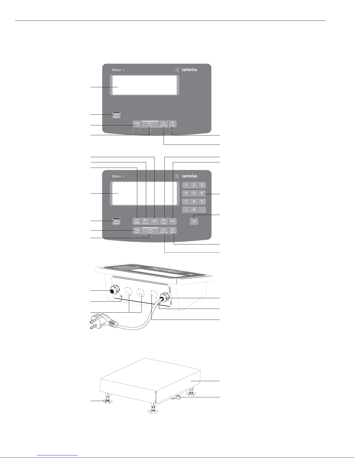
Display and Keypad
1 Display
(for details, see the chapter entitled
“Operating Design")
2 On/standby key
3 Zero key
4 Tare key
5 Function key (e.g., toggle between
gross and net values)
6 Print key (data output)
7 ID key
(for entering product information)
8 Numeric keypad
9 Info key (for viewing ID codes
and manual tare values)
10 Toggle key
(function depends on application)
11 OK key
(function depends on application)
12 Reference value key
(function depends on application)
13 Clear-function key
(function depends on application)
Back Panel of Display and Control Unit
14 Connector for weighing platform
15 Menu access switch
16 Optional:
Second interface (UniCOM)
17 Optional:
RS-232C interface (COM1)
18 Ground terminal
(equipotential bonding)
19 Power cord
Weighing Platform
20 Load plate
21 Level indicator (verified models only)
22 Leveling feet
General View of the Equipment
7
6
5
10
9
14
8
7
11
12
13
1
2
3
4
Midrics 1
Midrics 2
Midrics
display and
control unit
Midrics
weighing platform
19
18
17
14
15
16
21
20
22
6
5
1
2
3
4
Page 8

Keys
Operation of the Midrics
®
1 or Midrics
®
2 scale involves just a few keys.
These keys have one function during
measurement and another during
configuration. Some of the keys have
one function when pressed briefly
and another activated by pressing
and holding the key for longer than
2 seconds.
If a key is inactive, this is indicated
as follows when it is pressed:
– The error code “———-” is displayed
for 2 seconds. The display then returns
to the previous screen content.
Configure the operating menu for
the desired application program first
(printer settings, etc.). Then you can
begin weighing.
Input
Keypad Input
Labeled Keys
Some keys have a second function,
activated by pressing and holding
the key for at least 2 seconds.
Whether a function is available
depends on the operating state
and menu settings.
e On/standby
(in standby mode,
OFF is displayed).
( – Zero the scale
– Cancel calibration/adjustment
) – Tare the scale
k Toggle between 1
st
and 2ndweight
unit, or gross and net values,
or normal and 10-fold higher
resolution, depending on operating
menu settings
p – To print: press briefly
(< two seconds).
Midrics 2 only:
d ID key for entering product
information
Midrics 2 only:
I View application data or manual
tare values, depending on the key
pressed subsequently (e.g., ))
Midrics 2 only:
w Toggle between display modes
within an application program
Midrics 2 only:
O Save a value or start an application
program.
Midrics 2 only:
r Modify a reference value
Midrics 2 only:
c – Quit an application or delete
an input character
Midrics 2 only:
0, 1, 2 … 9
Enter numbers, letters and other
characters
Operating Design
8
Operating elements: Midrics®2
Page 9

Numeric Input Through the Keypad
(Midrics 2 only)
§ To enter numbers (one digit at a time):
Press 0, 1, 2 …9
§ To save input:
press the required key (e.g., )
to save manual tare input)
§ To delete a digit:
Press c
Loading a Tare Value from
the Weighing Platform
You can store the weight on
the weighing platform; for example,
as a tare weight, by pressing
the ) key
Input Through the
Digital Input Port
You can connect a remote hand switch
or foot switch to the input control line,
for use with all application programs.
Assign one of the following functions
to this switch in the operating menu,
under “
Control IO/ -> Control
input":
CTRL IO
CTRL INP
8
8.4 Universal IN
…
…
…
CTRL OUT
For a detailed list of menu items, please see
the chapter entitled “Configuration."
9
Page 10

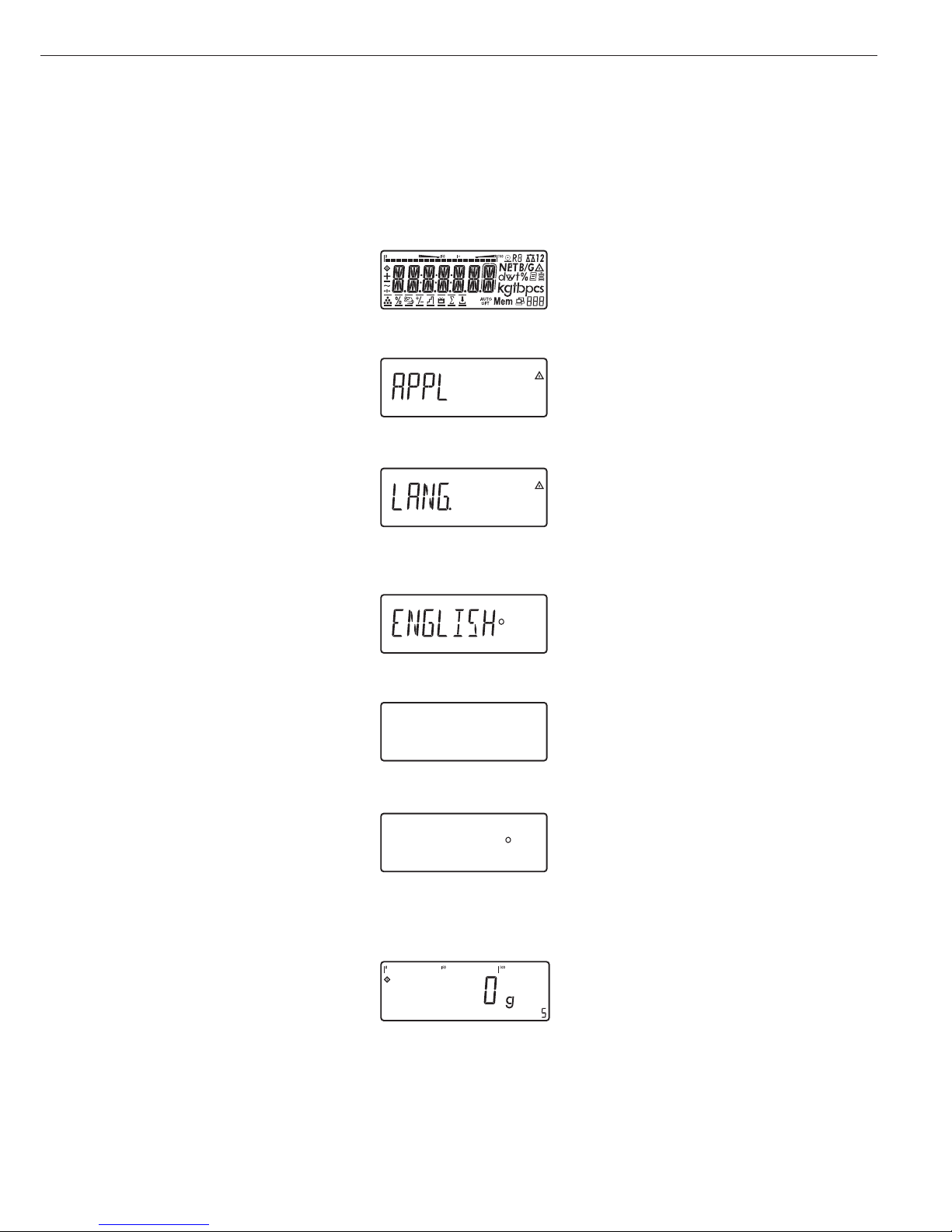
Display in Weighing Mode
The illustration above shows all display
segments and the symbols and other
elements used during normal weighing
operation.
1. Bar graph
– Shows the percentage of the
weighing platform's capacity that
is “used up" by the load on the
scale (gross value), or
– Shows the measured value in
relation to a target value
(with the Checkweighing or
Classification application)
2. Printing in progress
3. Display of the range on multiple-range
instruments
4. Indicates a net or gross value in
the main display (when data is stored
in tare memory)
5. Identifies the value on the main
display as calculated (value not valid
in legal metrology)
6. Battery symbol showing status of
rechargeable battery (empty outline
indicates battery is drained)
7. GMP-compliant printing in progress
(optional; with interface and “clock"
options)
8. Weight unit of the value displayed
9. Numeric display; e.g., showing
reference value (Midrics 2 only)
Midrics 2:
10. Symbol indicating data transfer:
– Interface initialized
– Flashes during data transfer
11. Symbols for reference updating
(Midrics 2 only)
– Auto: Depending on the weight
value, a reaction is triggered
in the application
– Opt: Automatic reference
updating has been performed
(Counting application)
12. Weight value or calculated value
(main display)
13. Application symbols for Midrics 2
applications:
A Counting
B Weighing in Percent
V Averaging (Animal Weighing)
H Checkweighing
W Classification
L Totalizing
R Net-total Formulation
Checkweighing:
Batching to a target value
Verified models only:
14. The “zero-setting" symbol is displayed
after the active scale or weighing
platform has been zeroed
15. Stability symbol
16. Plus or minus sign for the value
displayed
17. Busy symbol; indicates that an internal
process is in progress
There are two display modes:
– Normal operation (weighing mode)
– Operating menu (for configuration)
Weighing Mode: Display
of Measured and Calculated
Values (Main Display)
Application, printing and battery
symbols:
The application symbol indicates
the selected program; for example:
A Counting application symbol
S Printing mode active
T GMP printing mode active
The battery symbol b indicates
the charge level of the external
rechargeable battery.
Operating Design
10
13
4
5
6
7
8
9
1011
12
13
14
16
15
17
2
Page 11
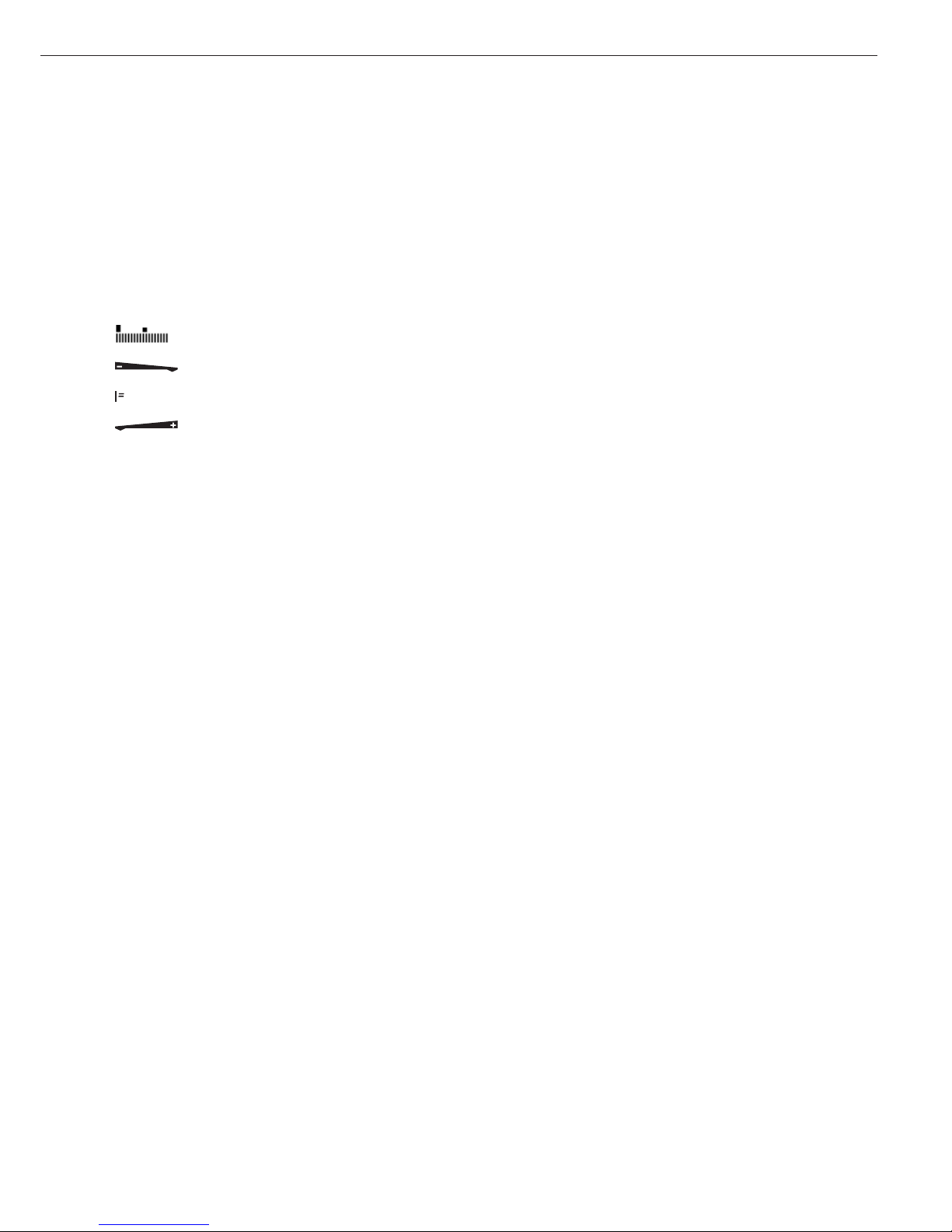
Bar graph
The bar graph shows the percentage of the
weighing platform's capacity that is “used
up" by the load on the scale (gross value).
0% Lower limit
100% Upper limit
The following symbols indicate tolerance
levels for Checkweighing:
Bar graph with 10% markings
Minimum in Checkweighing
Target in Checkweighing
Maximum
Plus/minus sign:
+ or - for weight value or calculated
value,
o when the weighing platform
is zeroed or tared.
Measured value/result line
This field shows weight values and
calculated values (alphanumeric characters)
Unit and stability
When the weighing system reaches
stability, the weight unit or the unit for
a calculated value is displayed here.
Tare in memory, calculated values:
The following symbols may be displayed
here:
a Calculated value (not valid in
legal-for-trade applications)
NET Net value
(gross weight minus tare)
B/G Gross value
(net value plus tare)
Data in tare memory, calculated values,
designation of the active weighing
platform
pt Identification of manual tare
input when viewing tare
information
Saving Data in Weighing Mode
All of the application parameters
saved (e.g., reference values) remain in
memory and are still available after
– the Midrics has been switched off
and back on again, or
– you return to the originally selected
application from a second one (e.g.,
when you switch from Averaging back
to Counting, all parameters saved
for Counting are available)
11
Page 12

Operating Menu Navigation
The keys below the readout let you
navigate the menu and define parameters
for configuration.
Opening the Menu
Press the e key to switch the Midrics
off and then on again; while all segments
are displayed, press the ) key briefly.
Navigating the Menu
( Close the active submenu and
return to the next higher menu level
(“back")
) – Press briefly:
Select and save a menu item
– Press and hold (> 2 seconds):
Exit the menu
k Show the next item on the same
menu level (the display scrolls
through all items in series)
p Print the menu settings starting
from the current position, or print
Info data
Alphanumeric Input in the Menu
( – Press briefly:
Activate character to the left
of the current character
(when first character is active:
exit input mode without saving
changes)
– Press and hold (> 2 seconds):
Exit input mode without saving
changes
) – Press briefly:
Confirm currently active character
and move cursor 1 position to
the right (after the last character:
save input)
– Press and hold (> 2 sec ):
Save current input and display
the menu item
k – Cursor in first position,
no characters entered yet:
Delete character(s) and enter 0
– Change the displayed character;
scroll forward (sequence:
0 through 9, decimal point,
minus sign, A to Z, space)
p – Cursor in first position,
no characters entered yet: Delete
entire string and enter a space
– Change the displayed character;
scroll backwards (sequence:
space, Z to A, minus sign, decimal
point, 9 through 0)
Numeric input in Midrics 2 operating
menu:
Enter values (date and time, etc.) using
the 10-key numeric keypad
Display of Menu Settings
The illustrations above show examples
of the main display during menu
configuration.
1 Selected menu item on the text
level (e.g. printer, for configuring
the connected printer)
2 Menu history (indicates the highest
menu level)
3 Indication that there are other
submenus
4 Highest level in numeric menu
5 Second level in numeric menu
6 Third level in numeric menu
Errors
– If a key is inactive, “-------" or
“No function" is displayed briefly
(2 seconds)
– Temporary errors are displayed for
2 seconds in the measured value/result
line (e.g.,
Inf 09); fatal errors are
displayed steadily (e.g.,
Err 101) until
the Midrics is reset (switched off and
then on again).
For a detailed description,
see “Error Codes" on page 89.
Data Output
Printer
You can connect two strip or label
printers to the Midrics 1 or Midrics 2
and have printouts generated at the
press of a key or automatically. You can
also configure separate summarized
printouts, and print a list of the active
menu settings. See “Configuring
Printouts" on page 82 for details.
Backup
Application parameters (such as
reference values) are saved when you
change application programs or switch
off the Midrics. You can assign a password to prevent unauthorized users
from changing settings in the “Device
parameters" menu under:
Setup
Password
See also pages 14 and 31.
Operating Design
12
Display of menu settings: Text menu (example) Display of menu settings: Numeric menu (example)
Page 13
You can configure the Midrics scale
by selecting parameters in the operating
menu. The parameters are combined
in the following groups (this is the
highest menu level):
– Application parameters
– Fn key function
– Device parameters (“
Setup")
– Device-specific information (“
Info")
– Language
When the scale is used in legal
metrology, not all parameters can
be accessed.
Factory-set parameters are identified
by an asterisk (“*") in the list starting
on page 16.
You can choose from six language
settings for the display of information:
– German
– English (factory setting)
– English with U.S. date/time format
– French
– Italian
– Spanish
Printing parameter settings:
§ Open the operating menu and
press the p key
Scope of printout:
Depends on the active menu level
Setting the Language
Setting the Language
Example: Selecting “U.S. Mode" for the language
e
Switch on the scale
)
While all segments are lit,
press the ) key
The first item in the main menu is shown:
APPL
k
Switch to the LANG. menu item
(press k repeatedly until
LANG.
is shown)
)
Select LANG. to open the submenu
for setting the language
The currently active language setting
is shown
k
Press k repeatedly until U.S. Mode
is displayed
)
Confirm this menu item
(
Exit this menu level and configure
other settings as desired, or
)
(press and hold) Exit the operating menu
Configuration
13
U.S. Mode
U.S. Mode
Page 14

Entering or Changing the Password
Example:
Assign a password (in this example,
AB2) to protect the application program settings APPL
and the device parameters SETUP from unauthorized changes
e
1. Switch on the scale
)
2. While all segments are lit,
press the ) key
The first item in the main
menu is shown:
APPL
k
3. Select the SETUP menu item
(press k repeatedly until
SETUP is displayed)
)
4. Open the SETUP menu
k
5. Select the PASSWORD menu
item (press k repeatedly
until
PASSWORD is displayed)
)
6. Open the PASSWORD menu
p, p
7. Enter the first character
using the p and k keys
(in this example:
A)
)
8. Save the character
p, p, p
9. Enter the second character
using the p and k keys
(in this example:
B)
)
10. Save the character
k, k, k
, 11. Enter the third character
using the p and k keys
(in this example:
2)
)
12. Save the password
(
13. Exit this menu level
to configure other menu
settings, or
)
14. Exit the operating menu
(press and hold the ) key)
To modify or delete a password:
Overwrite the old password
with the new password, or enter
a space as the password and
press ) to confirm
14
Page 15
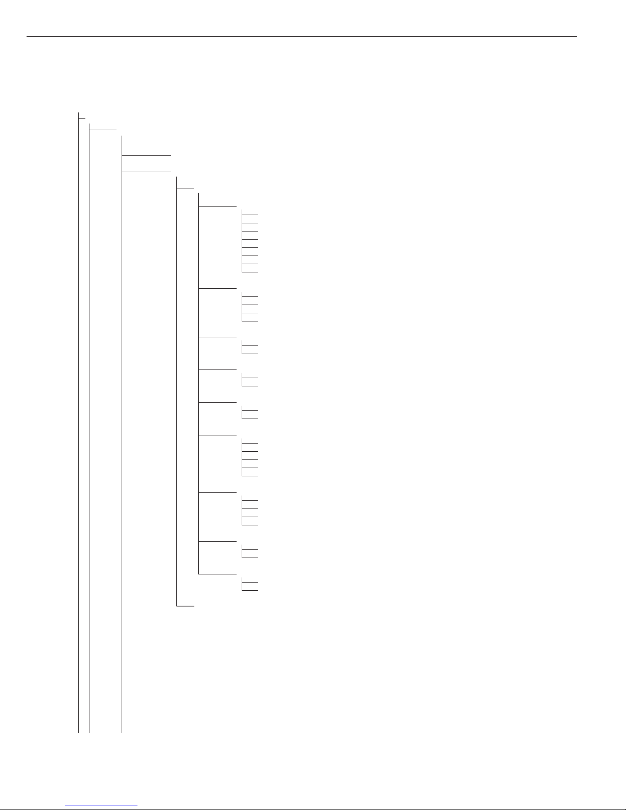
1stlevel 2ndlevel Function
display display
Menu
appl Select and configure application programs
W Basic weighing function
Z Counting
Z nm_ Neutral Measurement
V Averaging (animal weighing)
O Checkweighing
W Classification
L Weighing in percent
R Net-total formulation
L Totalizing
Fn-Key Define the function of the k key
off No function
gro net Gross/net toggling
2.unit Toggle between weight units
res 10 10-fold increased resolution
Setup Adapt Midrics to user requirements
wp1 Settings for weighing instrument on WP1
com1 Settings for the RS-232 interface
UNICOM Settings for the optional second interface
ctrl 10 Assign a function to the control inputs/outputs
barcode Set the bar code scanner function
prtprot Configure the printout
Utilit Operating parameters
time Set the time
Date Set the date
password Enter a password to protect menu settings
Info View device-specific information (service date, serial number, etc.)
Lang Select language for calibration, adjustment and GMP printouts
deutsch German
english English
u.s. mode English with U.S. date/time format
franc. French
ital. Italian
espanol Spanish
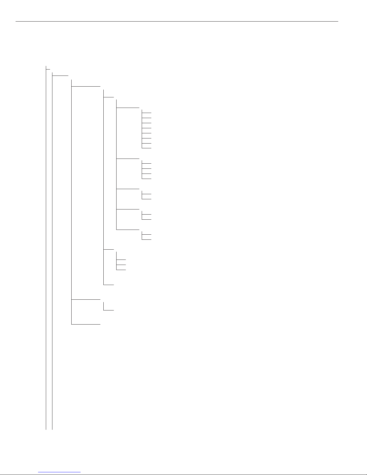
Operating Menu Overview
You can configure the Midrics to meet
individual requirements by entering
user data and setting selected parameters
in the operating menu.
Menu levels are identified by texts, and numeric codes identify the individual settings.
= Setting/function available on Midrics 2 only
15
Page 16
Operating Menu
= Setting/function available on Midrics 2 only
* Factory setting
Menu
appl Application Programs
W
Basic weighing function
3.5. Minimum load for automatic taring and automatic printing
3.5.1* 1 digit
3.5.2 2 digits
3.5.3 5 digits
3.5.4 10 digits
3.5.5 20 digits
3.5.6 50 digits
3.5.7 100 digits
3.5.8 200 digits
3.5.9 500 digits
3.5.10 1000 digits
3.7. Automatic taring: first weight tared
3.7.1* Off
3.7.2 On
9.1. Factory settings for all application programs
9.1.1 Yes
9.1.2* No
Z Counting
3.5. Minimum load for automatic taring and automatic printing
Numeric menu as for Weighing
3.6. Minimum load for initialization
3.6.1* 1 digit
3.6.2 2 digits
3.6.3 5 digits
3.6.4 10 digits
3.6.5 20 digits
3.6.6 50 digits
3.6.7 100 digits
3.6.8 200 digits
3.6.9 500 digits
3.6.10 1000 digits
3.7. Automatic taring: first weight tared
3.7.1* Off
3.7.2 On
3.8. Start application and load most recent application data when the Midrics is switched on
3.8.1 Automatic (on)
3.8.2* Manual (off)
3.9. Resolution for calculation of reference value
3.9.1* Display resolution
3.9.2 Display resolution + 1 decimal place
3.9.3 Display resolution + 2 decimal places
3.9.4 Internal resolution
3.11. Parameter for saving weight values (“storage parameter")
3.11.1* At stability
3.11.2 At increased stability
3.12. Reference sample updating (“APW update")
3.12.1 Off
3.12.3* Automatic
9.1. Factory settings for all application programs
9.1.1 Yes
9.1.2* No
16
Page 17

appl
Z nm
Neutral Measurement
3.5. Minimum load for automatic taring and automatic printing
Numeric menu as for Weighing
3.6. Minimum load for initialization
Numeric menu as for Counting
3.7. Automatic taring: first weight tared
3.7.1* Off
3.7.2 On
3.8. Start application and load most recent application data when the Midrics is switched on
3.8.1 Automatic (on)
3.8.2* Manual (off)
3.9. Resolution for calculation of reference value
3.9.1* Display resolution
3.9.2 Display resolution + 1 decimal place
3.9.3 Display resolution + 2 decimal places
3.9.4 Internal resolution
3.10. Decimal places in displayed result
3.10.1* None
3.10.2 1 decimal place
3.10.3 2 decimal places
3.10.4 3 decimal places
3.11. Parameter for saving weight values
3.11.1* At stability
3.11.2 At increased stability
9.1. Factory settings for all application programs
9.1.1 Yes
9.1.2* No
V Averaging (Animal Weighing)
3.5. Minimum load for automatic taring and automatic printing
Numeric menu as for Weighing
3.6. Minimum load for automatic start
Numeric menu as for Counting
3.7. Automatic taring: first weight tared
3.7.1* Off
3.7.2 On
3.8. Start application and load most recent application data when the Midrics is switched on
3.8.1 Automatic (on)
3.8.2* Manual (off)
3.18. Start of averaging routine
3.18.1* Manual
3.18.2 Automatic
3.19. Animal activity
3.19.1 0.1% of the animal/object
3.19.2* 0.2% of the animal/object
3.19.3 0.5% of the animal/object
3.19.4 1% of the animal/object
3.19.5 2% of the animal/object
3.19.6 5% of the animal/object
3.19.7 10% of the animal/object
3.19.8 20% of the animal/object
3.19.9 50% of the animal/object
3.19.10 100 % of the animal/object
3.20. Automatic printout of results
3.20.1* Off
3.20.2 On
17
Page 18
appl
V
Averaging (Animal Weighing)
3.21. Static display of result after load removed
3.21.1* Display is static until unload threshold reached
3.21.2 Display is static until c is pressed
9.1. Factory settings for all application programs
9.1.1 Yes
9.1.2* No
O Checkweighing
3.5. Minimum load for automatic taring and automatic printing
Numeric menu as for Weighing
3.6. Minimum load for initialization
Numeric menu as for Counting
3.7. Automatic taring: first weight tared
3.7.1* Off
3.7.2 On
3.8. Start application and load most recent application data when the Midrics is switched on
3.8.1 Automatic (on)
3.8.2* Manual (off)
4.2. Checkweighing range
4.2.1* 30 to 170%
4.2.2 10% to infinity
4.3. Activate control line for “Set” as:
4.3.1* “Set” output
4.3.2 Ready to operate (for process control systems)
4.4. Activation of outputs
4.4.1 Off
4.4.2 Always active
4.4.3 Active at stability
4.4.4* Active within checkweighing range
4.4.5 Active at stability within the checkweighing range
4.5. Parameter input
4.5.1* Min, max, target
4.5.2 Only target with percent limits
4.6. Automatic printing
4.6.1* Off
4.6.2 On
4.6.3 Only values within tolerance
4.6.4 Only values outside tolerance
4.7. Checkweighing toward zero
4.7.1* Off
4.7.2 On
4.7.3 On
9.1. Factory settings for all application programs
9.1.1 Yes
9.1.2* No
W Classification
3.5. Minimum load for automatic taring and automatic printing
Numeric menu as for Weighing
3.6. Minimum load for initialization
Numeric menu as for Counting
3.7. Automatic taring: first weight tared
3.7.1* Off
3.7.2 On
18
Page 19

appl
W Classification
3.8. Start application and load most recent application data when the Midrics is switched on
3.8.1 Automatic (on)
3.8.2* Manual (off)
4.3. Activate control line for “Set” as:
4.3.1* “Set” output
4.3.2 Ready to operate (for process control systems)
4.7. Activation of outputs
4.7.1 Off
4.7.2 Always active
4.7.3* Active at stability
4.8. Number of classes
4.8.1* 3 classes
4.8.2 5 classes
4.9. Parameter input
4.9.1* Weight values
4.9.2 Percentage
4.10. Automatic printing
4.10.1* Off
4.10.2 On
9.1. Factory settings for all application programs
9.1.1 Yes
9.1.2* No
L Weighing in Percent
3.5. Minimum load for automatic taring and automatic printing
Numeric menu as for Weighing
3.6. Minimum load for initialization
Numeric menu as for Counting
3.7. Automatic taring: first weight tared
3.7.1* Off
3.7.2 On
3.8. Start application and load most recent application data when the Midrics is switched on
3.8.1 Automatic (on)
3.8.2* Manual (off)
3.9. Resolution for calculation of reference value
3.9.1* Display resolution
3.9.2 Display resolution + 1 decimal place
3.9.3 Display resolution + 2 decimal places
3.9.4 Internal resolution
3.10. Decimal places in displayed result
3.10.1* None
3.10.2 1 decimal place
3.10.3 2 decimal places
3.10.4 3 decimal places
3.11. Parameter for saving weight values
3.11.1* At stability
3.11.2 At increased stability
3.15. Display
3.15.1* Residue
3.15.2 Loss
9.1. Factory settings for all application programs
9.1.1 Yes
9.1.2* No
19
Page 20

appl
R
Net-total Formulation (2ndTare Memory)
3.5. Minimum load for automatic taring and automatic printing
Numeric menu as for Weighing
3.6. Minimum load for automatically saving/transferring values
Numeric menu as for Counting
3.7. Automatic taring: first weight tared
3.7.1* Off
3.7.2 On
3.17. Printout when value is saved in totalizing memory
3.17.1 Automatic printout of results off
3.17.2* Generate printout with complete standard configuration each time O is pressed
3.17.3 Generate printout with complete standard configuration only the first time O is pressed
9.1. Factory settings for all application programs
9.1.1 Yes
9.1.2* No
L Totalizing
3.5. Minimum load for automatic taring and automatic printing
Numeric menu as for Weighing
3.6. Minimum load for automatically saving/transferring values
Numeric menu as for Counting
3.7. Automatic taring: first weight tared
3.7.1* Off
3.7.2 On
3.8. Start application and load most recent application data when the Midrics is switched on
3.8.1 Automatic (on)
3.8.2* Manual (off)
3.16. Values saved automatically
3.16.1* Off
3.16.2 On
3.17. Individual component data printed when value is added to totalizing memory
3.17.1 Automatic printout of results off
3.17.2* Individual printout of a totalizing item when O is pressed
3.17.3 Components of transaction printed when O is pressed
9.1. Factory settings for all application programs
9.1.1 Yes
9.1.2* No
off Disabled
fn-key k Key Assignment
off * No k key function
gro net Gross/net toggling
2. unit Show 2ndWeight unit
res 10 10-fold increased resolution Display: max. 5 seconds
20
Page 21
Setup Device Parameters
Password prompt displayed if a password is configured
wp-1
1
Weighing platform 1
(Display designation of this menu level: 1)
1.1. Adapt weighing instrument to ambient conditions (adapt filter)
1.1.1 Very stable conditions
1.1.2* Stable conditions
1.1.3 Unstable conditions
1.1.4 Very unstable conditions
1.2. Application filter
1.2.1* Final readout
1.2.2 Filling mode
1.2.3 Low filtering
1.2.4 Without filtering
1.3. Stability range
1.3.1 4 digit
1.3.2 1 digit
1.3.3 1 digit
1)
1.3.4* 2 digits
1)
1.3.5 4 digits
1)
1.3.6 8 digits
1)
1.4. Stability symbol delay
1.4.1 No delay
1.4.2* Short delay
1.4.3 Average delay
1.4.4 Long delay
1.5. Taring
1)
1.5.1 Without stability
1.5.2* After stability
1.6. Auto zero
1.6.1* On
1.6.2 Off
1.7. Weight Unit 1
2)
1.7.1 Grams / o
1.7.2 Grams / g
1.7.3 Kilograms / kg
1.7.4 Carats / ct
1)
1.7.5 Pounds / lb
1)
1.7.6 Ounces / oz
1)
1.7.7 Troy ounces / ozt
1)
1.7.8 Hong Kong taels / tlh
1)
1.7.9 Singapore taels / tls
1)
1.7.10 Taiwanese taels / tlt
1)
1.7.11 Grains /GN
1)
1.7.12 Pennyweights / dwt
1)
1.7.14 Parts per pound / lb
1)
1.7.15 Chinese taels / tlc
1)
1.7.16 Mommes / mom
1)
1.7.17 Austrian carats / k
1)
1.7.18 Tola / tol
1)
1.7.19 Baht / bat
1)
1.7.20 Mesghal / MS
1)
1.7.21 Tons / t
1.7.22 Pounds: ounces
1)
1.8. Display accuracy 1
1)
1.8.1* All digits
1.8.2 Reduced by 1 decimal place for load change
1.8.14 10-fold increased resolution
1.8.15 Resolution increased by 2 scale intervals (e.g., 5 g to 1 g)
1.8.16 Resolution increased by 1 scale interval
(e.g., from 2 g to 1 g or from 10 g to 5 g)
1)
Not available on instruments verified for use in legal metrology
2)
Depends on weighing platform model
21
Page 22

Setup
wp-1
1
1.9. Calibration and adjustment
1.9.1* External calibration/adjustment; default weight
1.9.3 External calibration/adjustment; weight can be selected under menu item 1.18.1
1.9.10 No function when you press and hold ) > 2 sec
1.10. Calibration/adjustment sequence
1.10.1 Calibration with automatic adjustment
1.10.2* Calibration with adjustment triggered manually
1.11. Zero-setting range
1.11.1 1 percent/max. cap.
1.11.2* 2 percent/max.cap.
1.12. Initial zero-setting range
1.12.2 2 percent/max. cap.
1.12.3 5 percent/max.cap. (setting depends on model)
1.12.4* 10 percent/max.cap.
1.13. Tare/zero at power on
1.13.1* On
1.13.2 Off, load previous tare value
1.13.3 Only zero at power on
1.15. Calibration prompt
1.15.1* Off
1.15.2 Calibration prompt (W) flashes on the display
1.16. External calibration/adjustment
1)
1.16.1* Accessible
1.16.2
2)
Blocked
1.17. Calibration weight unit
1.17.1 Grams
1.17.2* Kilograms
1.17.3 Tons
1.17.4 Pounds
1)
1.18. Enter calibration weight
1.18.1 External user-defined weight (enter value; e.g.: 10,000 kg)
3.1. Weight unit 2
3)
3.1.1 Grams / o
3.1.2 Grams / g
3.1.3* Kilograms / kg
3.1.4 Carats /ct
1)
3.1.5 Pounds /lb
1)
3.1.6 Ounces /oz
1)
3.1.7 Troy ounces / ozt
1)
3.1.8 Hong Kong taels / tlh
1)
3.1.9 Singapore taels / tls
1)
3.1.10 Taiwanese taels / tlt
1)
3.1.11 Grains / GN
1)
3.1.12 Pennyweights / dwt
1)
3.1.14 Parts per pound / lb
1)
3.1.15 Chinese taels / tlc
1)
3.1.16 Mommes / mom
1)
3.1.17 Austrian carats /k
1)
3.1.18 Tola / tol
1)
3.1.19 Baht / bat
1)
3.1.20 Mesghal / MS
1)
3.1.21 Tons / t
3.1.22 Pounds:ounces
1)
3.2. Display accuracy 2
1)
3.2.1* All digits
3.2.2 Reduced by 1 decimal place for load change
3.2.14 10-fold increased resolution
3.2.15 Resolution increased by 2 scale intervals (e.g., 5 g to 1 g)
3.2.16 Resolution increased by 1 scale interval (e.g., 2 g to 1 g or from 10 g to 5 g)
3.3. Weight unit 3
3)
(settings as for 3.1, “Weight unit 2”)
3.4. Display accuracy
3)
(settings as for 3.2, “Display accuracy 2”)
9.1. Restore factory settings in WP1 numeric menu
9.1.1 Yes
9.1.2* No
1)
= Not available on instruments verified for use in legal metrology
2)
= Factory setting on instrument verified for use in legal metrology
3)
= Menu depends on weighing platform model
22
Page 23
Setup
Com1
2
Interface port 1 (optional)
(Display designation of this menu level: 2)
off
*
Off
datProt Data protocol
sbi
*
SBI: standard version
5.1. Baud rate
5.1.1 150 baud
5.1.2 300 baud
5.1.3 600 baud
5.1.4* 1200 baud
5.1.5 2400 baud
5.1.6 4800 baud
5.1.7 9600 baud
5.1.8 19,200 baud
5.2. Parity
5.2.2 Space
2)
5.2.3 Odd
5.2.4 Even
5.2.5 None
3)
5.3. Number of stop bits
5.3.1* 1 stop bit
5.3.2 2 stop bits
5.4. Handshake mode
5.4.1 Software handshake
5.4.3* Hardware handshake, 1 character after CTS
5.6. Number of data bits
5.6.1* 7 data bits
5.6.2 8 data bits
6.1. Data output: manual/automatic
6.1.1 Manual without stability
6.1.2* Manual after stability
6.1.4 Automatic without stability
6.1.5 Automatic with stability
6.1.7 Protocol for computer (PC)
6.3. Time-dependent automatic data output
6.3.1* 1 display update
6.3.2 2 display updates
6.3.4 10 display updates
6.3.7 100 display updates
7.2. Data output: line format for printout
7.2.1 For raw data: 16 characters
7.2.2* For other applications: 22 characters
9.1. Restore factory settings in numeric menu COM1: SBI
9.1.1 Yes
9.1.2* No
xbpi-232 XBPI-232
1)
Menu depends on weighing platform model
2)
not with setting 5.6.2 (8 bits)
3)
not with setting 5.6.1 (7 bits)
23
Page 24

Setup
Com1
2
datProt
SMA SMA interface function
5.1. Baud rate
5.1.1 150 baud
5.1.2 300 baud
5.1.3 600 baud
5.1.4 1200 baud
5.1.5 2400 baud
5.1.6 4800 baud
5.1.7* 9600 baud
5.1.8 19,200 baud
5.2. through 5.6.
Numeric menu as for SBI
Printer Printer configuration
YDP01IS YDP01IS
line
*
Strip printer
label Label printer
lab ff Label printer with manual feed
YDP02 YDP02 variants
5.1. Baud rate
5.1.4* 1200 baud
5.1.5 2400 baud
5.1.6 4800 baud
5.1.7 9600 baud
5.2. Parity
5.2.2 Space
5.2.3* Odd
5.2.4 Even
5.3. Number of stop bits
5.2.2 Space
5.3.1* 1 stop bit
5.3.2 2 stop bits
5.4. Handshake mode
5.4.1 Software handshake
5.4.3* Hardware handshake, 1 character after CTS
YDP03 YDP03-0CE
5.1. Baud rate
5.1.4* 1200 baud
5.1.5 2400 baud
5.1.6 4800 baud
5.1.7 9600 baud
5.1.8 19,200 baud
5.2. through 5.4.
Numeric menu as for COM02
YDP02IS YDP02IS
line
*
Strip printer
label Label printer
24
Page 25
Setup
Com1
2
Printer
Uni-pri Universal interface
5.1. Baud rate
5.1.1 150 baud
5.1.2 300 baud
5.1.3 600 baud
5.1.4 1200 baud
5.1.5 2400 baud
5.1.6 4800 baud
5.1.7* 9600 baud
5.1.8 19,200 baud
5.2. Parity
5.2.2 Space
1)
5.2.3 Odd
5.2.4 Even
5.2.5* None
2)
5.3. Number of stop bits
5.3.1* 1 stop bit
5.3.2 2 stop bits
5.4. Handshake mode
5.4.1* Software handshake
5.4.3 Hardware handshake, 1 character after CTS
5.6. Number of data bits
5.6.1 7 data bits
5.6.2* 8 data bits
YDP04IS
*
YDP04IS
line
*
Strip printer
label Label printer
lab ff Label printer with manual feed
yam01is YAM01IS as electronic memory for print data
Memory Verifiable data memory
yam01is YAM01IS external data memory
Off Disabled
1)
not with setting 5.6.2 (8 bit)
2)
not with setting 5.6.1 (7 bits)
25
Page 26

Setup
unicom
3
Interface port 2 (Optional)
(Display designation of this menu level: 3)
off
*
Off
datprot Data protocol
sbi
*
SBI: standard version
5.1. through 9.1.
Numeric menu as for COM1
bpi-232 XBPI-232
bpi-485 XBPI-485
0 to 31 Network address: From 0 to 31 inclusive
sma SMA interface function
5.1. through 5.6.
Numeric menu as for COM1
ETHER
src-ip Source IP: 192.168.0.1*
src.name Source name (16 characters maximum)
lis.port Listen on port: 49155*
supnet Subnet mask:255.255.255.0*
gate-ip Gateway IP: 0.0.0.0*
dest-ip Destination IP: 0.0.0.0*
dest.por Destination port: 49155*
Protocol TCP*
UDP
Mode SBI (server)* 6.1. Manual output/automatic
6.1.1 Manual without stability
6.1.2 * Manual after stability
6.1.4 Automatic without stability
6.1.5 Automatic with stability
6.1.7 Data record for computer printout
7.2. Data output: line format for printout
7.2.1 For raw data: 16 characters
7.2.2* For other apps.: 22 characters
SBI-C/S (client) 6.1. Manual output/automatic
6.1.1 Manual without stability
6.1.2 * Manual after stability
6.1.4 Automatic without stability
6.1.5 Automatic with stability
6.1.7 Data record for computer printout
XBPI 6.3. Time-dependent automatic
data output
SMA 6.3.1 * 1 display update
Modbus/TCP 6.3.2 2 2 display updates
6.3.4 10 10 display updates
6.3.7 100 100 display updates
7.2. Data output: line format for printout
7.2.1 For raw data: 16 characters
7.2.2* For other apps.: 22 characters
26
Page 27

Setup
uniCom1
3
Second interface (optional)
Printer Printer configuration
YDP01IS YDP01IS
line
*
Strip printer
label Label printer
lab ff Label printer with manual feed
YDP02 YDP02
5.1. through 5.4.
Numeric menu as for COM1
YDP03 YDP03-0CE
5.1. through 5.4.
Numeric menu as for COM1
YDP02IS YDP02IS
line
*
Strip printer
label Label printer
Uni-pri Universal interface
5.1. through 5.6.
Numeric menu as for COM1
YDP04IS
*
YDP04IS
line
*
Strip printer
label Label printer
lab ff Label printer with manual feed
yam01is YAM01IS as electronic memory for print data
Analog Analog data output port for PLC operation
8.12. Analog output: value
8.12.1* Net value
8.12.2 Gross value
8.13. Analog output: error indicator
8.13.1* High level (20 mA)
8.13.2 Low level (0/4 mA). When menu is open or during calibration:
0/4 mA on this interface.
8.14. Analog output: mode
8.14.1*
1)
Zero to maximum capacity
8.14.2 Minimum/maximum values
8.15. Analog output: min./max.
8.15.1
2)
Min. (0/4 mA) input in kg
8.15.2 Max. (20 mA) input in kg
Memory Verifiable data memory
yam01is YAM01IS external data memory
1)
When setting 8.14.1 is active, analog data output only works for XBPI weighing instruments
2)
not with setting 8.14.1
27
Page 28

Setup
ctrl io
4
Control inputs/outputs
(Display designation of this menu level: 4)
ctr inp Control inputs
For YDO01M-232CO; Option A1
8.4. Function for external control inputs (TTL)
8.4.1* Trigger p key function
8.4.2 Trigger p key (> 2 sec) function
8.4.3 Trigger ) key function
8.4.4 Trigger ) key (> 2 sec) function
8.4.5 Trigger k key function
8.4.7 Trigger O key function Midrics 2 only
8.4.8 Combined zero/tare function
8.4.9 Trigger ( key function
8.4.10 Trigger p key function
8.4.11 Trigger c key function Midrics 2 only
8.4.12 Trigger I key function Midrics 2 only
For YDO01M-IO; Option A5
8.17. External input 1
8.17.1 Trigger p key function
<as under 8.4> <as under 8.4>
8.17.12 Trigger I key function Midrics 2 only
8.18. External input 2
8.26.1 Trigger p key function
<as under 8.4> <as under 8.4>
8.18.12 Trigger I key function Midrics 2 only
8.19. External input 3
8.27.1 Trigger p key function
<as under 8.4> <as under 8.4>
8.19.12 Trigger I key function Midrics 2 only
8.20. External input 4
8.28.1 Trigger p key function
<as under 8.4> <as under 8.4>
8.20.12 Trigger I key function Midrics 2 only
8.21. External input 5
8.21.1 Trigger p key function
<as under 8.4> <as under 8.4>
8.21.12 Trigger I key function Midrics 2 only
ctr out Control outputs
For YDO01M-IO; Option A5
8.24. External output 1
8.24.1* Weighing instrument ready to operate
8.24.2 Weighing instrument stable
8.24.3 Weighing instrument overflow (“H")
8.24.4 Weighing instrument underflow (“L")
8.24.5 Value in tare memory
8.24.6 Below minimum sample quantity Midrics 2 only
8.24.7 Over minimum sample quantity Midrics 2 only
8.24.8 Lighter Midrics 2 only
8.24.9 Equal Midrics 2 only
8.24.10 Heavier Midrics 2 only
8.24.11 Set Midrics 2 only
8.25. External output 2
8.25.1 Weighing instrument ready to operate
<as under 8.24> <as under 8.24>
8.25.11 Set
8.26. External output 3
8.26.1 Weighing instrument ready to operate
<as under 8.24> <as under 8.24>
8.26.11 Set
8.27. External output 4
8.27.1 Weighing instrument ready to operate
<as under 8.24> <as under 8.24>
8.27.11 Set
8.28. External output 5
8.28.1 Weighing instrument ready to operate
<as under 8.24> <as under 8.24>
8.28.11 Set
2828
Page 29

Setup
barcode
5
Bar code
(Display designation of this menu level: 5)
ref
*
Store value as reference weight
tare
*
Store as tare value (i.e., tare the scale)
1D1 Store value as ID code 1
Input Enter value on display (triggered when a key is pressed)
Header Store value as tare or ID code, depending on bar code header
ext.keyb External computer keypad
prtprot
6
Printouts
(Display designation of this menu level: 6)
7.4. Header input
7.4.1 (blank) Header line 1 (max. 20 characters); example: “MEYER'S"
7.4.2 (blank) Header line 2 (max. 20 characters); example: “STEEL"
7.4.3 (ID 1) ID code name for ID 1 (max. 40 characters)
7.4.4 (ID 2) ID code name for ID 2 (max. 40 characters)
7.4.5 (ID 3) ID code name for ID 3 (max. 40 characters)
7.4.6 (ID 4) ID code name for ID 4 (max. 40 characters)
7.5. COM1 interface
7.5.1* 1 printout
7.5.2 2 printouts
7.6. Optional “UniCOM” interface
7.6.1* 1 printout
7.6.2 2 printouts
7.7. COM1 interface:
Configure standard printout (press p, O)
7.7.1*
1)
Header lines 1, 2 (content: see menu codes 7.4.x)
7.7.2*
1)
Date and time
7.7.3*
1)
Initialization data for the application program
7.7.4*
1)
Weighing instrument designation
7.7.5*
1)
Result from the application program
7.7.6*
1)
ID codes 1 and 2
7.7.7
1)
2 additional blank lines
7.7.8
1)
3 additional blank lines
7.8. Optional “UniCOM” interface
Configure standard printout (press p, O)
7.8.1*
1)
Header lines 1, 2 (content: see menu codes 7.4.x)
7.8.2*
1)
Date and time
7.8.3*
1)
Initialization data for the application program
7.8.4*
1)
Weighing instrument designation
7.8.5*
1)
Result from the application program
7.8.6*
1)
ID codes 1 and 2
7.8.7
1)
2 additional blank lines
7.8.8
1)
3 additional blank lines
7.9. COM1 interface:
Print results when c pressed in
Totalizing and Net-total applications
7.9.1*
1)
Header lines 1, 2 (content: see menu codes 7.4.x)
7.9.2*
1)
Date and time
7.9.4*
1)
Weighing instrument designation
7.9.5*
1)
Result from the application program
7.9.7
1)
2 additional blank lines
7.9.8
1)
3 additional blank lines
1)
More than one can be selected
29
Page 30

Setup
prtprot
6
7.10. Optional “UniCOM” interface
Print results when c pressed in
Totalizing and Net-total applications
7.10.1*
1)
Header lines 1, 2 (content: see menu codes 7.4.x)
7.10.2*
1)
Date and time
7.10.4*
1)
Weighing instrument designation
7.10.5*
1)
Result from the application program
7.10.7
1)
2 additional blank lines
7.10.8
1)
3 additional blank lines
7.13 GMP data record or printout
7.13.1 Off
7.13.2 On for one result
7.13.3 On for multiple result
7.14. Date/time printout line: Time not printed
7.14.1* Off
7.14.2 On
7.15. One-time automatic printout at stability
7.15.1* Off
7.15.2 On
7.16. FlexPrint
7.16.1* Off
7.16.2 On
7.17. Decimal separator
7.17.1* Period
7.17.2 Comma
9.1. Restore factory settings of the numeric menu for data protocol
9.1.1 Yes
9.1.2* No
utilit
7
Operation
(Display designation of this menu level: 7)
8.3. Keys
8.3.1* All available
8.3.2 All blocked
8.3.3 Keys 0, 1, 2, etc. blocked Midrics 2 only
8.3.5 ( key blocked
8.3.6 ) key blocked
8.3.7 k key block
8.3.9 p key block
8.3.12 c key blocked Midrics 2 only
8.3.13 r key blocked Midrics 2 only
8.3.14 O key blocked Midrics 2 only
8.3.15 W key blocked Midrics 2 only
8.3.16 I key blocked Midrics 2 only
8.3.18 d key blocked Midrics 2 only
8.7. Automatic shutoff of display and control unit
8.7.1 Automatic shutoff acc. to menu item 8.9.
8.7.2* No automatic shutoff
8.8. Display lighting
8.8.1* On
8.8.2 Off
8.8.3 Automatic shutoff acc. to menu item 8.9.
8.9. Timer mode
8.9.1* After 1 + 1 minute not in use
(after 1 min.: warning
2)
is displayed for 1 minute)
8.9.2 After 2 + 2 minutes not in use
(after 2 min.: warning
2)
is displayed for 2 minutes)
8.9.3 After 5 + 5 minutes not in use
(after 5 min.: warning
2)
is displayed for 5 minutes)
8.12. Show geographical data before calibration
8.12.1* No
8.12.2 Yes
9.1. Restore factory settings of the numeric operating menu
9.1.1 Yes
9.1.2* No
1)
More than one can be selected
2)
Warning: the W symbol and weighing platform numbers 1 and 2 flash simultaneously
30
Page 31

Setup
time
Time (optional)
Format for setting the time (example): 10.07.41 (hours.minutes.seconds)
date Date (optional)
Format for setting the date (example): 01.05.07 (day.month.year);
U.S. mode: (month.day.year)
code Password
Set, change and delete password here.
Max. 8 characters); example: 12345678
Info Device information
Service Service information
10.04.02
1
Service date
term Display and control unit (“terminal”)
1: MW2P1 Model
2: 10405355 Serial number
3: 01.24.01 Software version
4: 00.37.01 Appl. software
5: 52 Geographical latitude (in degrees)
1)
6: 1 50 Geographical altitude (in meters)
1)
7: 8.91 Acceleration of gravity m/s
21)
Flex-Inf Flex Print
applset File name
2)
ID 123 ID
2)
v 123 Version
2)
Lang. Language for calibration/adjustment
and GMP printouts
deutsch German
english
*
English
u.s. mode English with U.S. date/time format
franc. French
ital. Italian
espanol Spanish
1)
Output: either latitude and altitude or acceleration of gravity (depends on the input before verification)
2)
These three parameters are shown for each file loaded
31
Page 32

Basic Weighing Function
Weighing W
The basic weighing function is always
accessible and can be used alone or in
combination with application programs,
such as Counting, Checkweighing,
Weighing in Percent, etc.
Features
– Zero the scale (
– Store the weight on the platform
as tare by pressing )
Midrics 2 only:
– Use the numeric keys to enter a tare
weight (press ) to save)
– Tare container weight automatically
– Delete tare values by entering 0
(press ) to save)
–
Press k to toggle the display between:
– Gross and net values, or
– Normal and 10-fold increased
resolution (displayed for max.
5 seconds)
Midrics 2 only:
– Individual ID codes for weight values
– Print weight values:
– Manually, by pressing p
– Automatically (see “Data Output
Functions")
– With GMP-compliant format
(see “Data Output Functions")
– Restore factory settings by selecting
the corresponding menu setting
Automatic Taring
The first weight on the scale that
exceeds the preset minimum load is
stored in the tare memory at stability.
The values for subsequent loads are
stored as weight values. The scale
returns to the initial state when the
load is less than 50% of the minimum
load.
Minimum Load
To tare container weights automatically, set the minimum load in the
operating menu.
You can choose from 10 settings,
defined in scale intervals (digits),
ranging from:
1 digit (no minimum load)
to
1000 digits
The “digits" here refer to the scale
intervals in the connected weighing
platform. Example: If the scale interval
(d) is 1000 g and the minimum load
is set to 1000 digits (=1000 scale
intervals), a load of at least 1000 g
is required for autotaring.
Automatic Printing
The first weight value that exceeds
the minimum load is printed.
Device Parameters
Keys
The keypad can be blocked.
There are four settings to choose from:
– All keys unblocked
– All keys blocked except e and M
– Numeric keypad blocked
– One specified key blocked
(see the menu in the chapter entitled
“Configuration" for options)
Display
You can have the display backlighting
shut off automatically when not in use
Automatic Shutoff
You can have the display and control
unit shut off automatically.
Timer Mode
There are three timer settings for
the shutoff functions: two, four and
ten minutes.
Settings
See the chapter entitled
“Configuration."
Operation
32
Page 33

33
Example with Midrics 2:
Switch on; zero; tare container weight; place sample in container;
toggle display to gross weight, second weight unit or 10-fold higher resolution; print results.
Display with tared scale and
sample in container
k
6. Toggle display; readout
depends on your settings:
Gross weight (in this example,
50 g for container +120.2 g
substrate)
or
display in 2nd weight unit
(in this example, kg) or
Weight displayed in second
weight unit
(in this example, kg)
or
Weight displayed with
10-fold increased resolution
k
7. Return to previous display
(if 10-fold increased resolution
is shown, display returns to
previous readout automatically
after 10 seconds.)
p
8. Print results
ACE HARDWARE
GOETTINGEN
24.02.2006 15:10
--------------------
G# + 170.2 g
T + 50.0 g
N + 120.2 g
--------------------
e
1. Switch on the scale
All display segments are
shown for about 1 second
(self-test)
Display with no load on scale
(
2. Zero the scale
Display with no load on scale
3. Place container on weighing
platform
Container weight is displayed
)
4. Tare the scale
Display (
net) when tared with
container
5. Place sample in container
(in this example, 120.2 g)
Page 34

Example with Midrics 2:
Enter the tare value using the keypad; print the results
e
1. Switch on the scale
The automatic self-test runs.
Once a readout is shown,
the Midrics is automatically
zeroed and ready to operate.
Press ( to reset the
unloaded weighing platform
to zero at any time.
250
2. Enter the tare weight in the
current weight unit using
the keypad (in this example,
250 g).
)
3. Save the tare weight.
4. Place the sample (in this
example, 2000 g) in
its container on the scale.
Read the result
k
5. Toggle the display from net
to gross weight values.
The display shows the gross
weight (in this example,
250 g for the container plus
2000 g for the sample).
k
6. Return to the previous display.
p
7. Print the results.
--------------------
G# + 2.250 kg
T + 0.000 kg
PT2 + 0.250 kg
N + 2.000 kg
--------------------
34
Example with Midrics 2
Tare the scale by placing a container on the weighing platform
e
1. Switch on the scale
The automatic self-test runs.
Once a readout is shown,
the Midrics is automatically
zeroed and ready to operate.
Press ( to reset the
unloaded weighing platform
to zero at any time.
2. Place empty container on
the platform
)
3. Tare the scale.
Note: If the automatic tare
function is active, you do not
need to press ) to tare the
scale; the tare weight is stored
automatically when you place
the container on the platform.
Wait until a zero value is
displayed together with the
NET symbol.
4. Place sample on the platform
Wait until the weight unit
symbol is displayed
(indicating stability) and
read the weight value
Page 35

35
e
1. Switch on the scale
The automatic self-test runs.
Once a readout is shown,
the Midrics is automatically
zeroed and ready to operate.
Press ( to reset the
unloaded weighing platform
to zero at any time.
2. Place empty container on
the platform
)
3. Tare the instrument
Note: If the automatic tare
function is active, you do not
need to press ) to tare the
scale; the tare weight is stored
automatically when you place
the container on the platform.
Wait until a zero value is
displayed together with the
NET symbol.
4. Place the sample in its
packaging (second tare value)
in the container.
250
5. Enter the tare weight of the
packaging in the current
weight unit using the keypad
(in this example, 250 g).
)
6. Save the package weight
you entered (the two tare
values are added together).
Read the net weight
p
7. Print the results.
G# + 6.433 kg
T + 4.183 kg
PT2 + 0.250 kg
N + 2.000 kg
--------------------
0
8. Clear the tare memory:
Enter a zero (“0") using the
keypad
)
9. Save the value entered (0).
This deletes tare values;
the display shows the gross
value.
p
10. Print the results.
G# + 6.433 kg
T + 0.000 kg
N + 6.433 kg
--------------------
Example with Midrics 2:
Weigh with varying tare values; print the results; delete tare values
Page 36

Calibration and Adjustment
Purpose
Perform calibration to determine the
difference between the value displayed
and the actual weight on the platform.
Calibration does not entail making
any changes within the weighing
instrument.
Perform adjustment to eliminate any
difference determined, or to reduce
it to a level that is within the applicable
tolerance limits.
Configuration for Use in Legal
Metrology
To configure the Midrics for use in
legal metrology (select VERIF. in ADC
configuration), adjust the switch on the
back of the display and control unit.
The switch is covered by a protective
cap.
Position:
§ Switch on the right: For use in
legal metrology
§ Switch on the left: External calibration/
adjustment accessible
1
) = Setting cannot be changed on scales
verified for use in legal metrology
2
) = Factory setting on instruments verified
for use in legal metrology
Features
You can configure the parameters
listed below in the operating menu.
Which of the features listed here are
available depends on the connected
weighing platform.
– External calibration/adjustment blocked
in verified weighing instruments
– External calibration/adjustment with
the default weight value or standard
weight (not available on verified
instruments). Configure under:
Setup
wp-1
1.9.
: (Calibration and adjustment)
– Specify the weight for external
calibration/adjustment:
Setup
wp-1
1.18.
: (Enter calibration weight)
– Block the ) key to prevent use of the
two functions described above (1.9.10):
Setup
wp-1
1.9.
: (Calibration and adjustment)
– Calibrate first; then adjust
automatically or manually (not on
verified weighing instruments):
Setup
wp-1
1.10.
: (Calibration/adjustment
sequence)
– Flashing
WP symbol as adjustment
prompt. If more than one weighing
platform is connected, the platform
number is also displayed:
Setup
wp-1
1.15.
: (Calibration prompt)
– Block external calibration/adjustment:
Setup
wp-1
1.16.
: (External calibration)
Note
On verified weighing instruments,
the external calibration/adjustment
function is available only when the
menu access switch is in the “open"
position, which entails breaking the
verification seal. The equipment must
be re-verified after the seal has been
broken.
Preparation
§ Switch on the scale: Press e
§ While all segments are lit,
press the ) key
§ Select the Setup menu: Press k
repeatedly until
Setup is displayed
§ Open the Setup menu:
Press the ) key
$ Select weighing platform 1, “
WP1”:
Press the ) key, or
$ Select interface 1, “
COM1" or interface 2,
“
COM2" (depending on the interface
used): Press the ) key
Setup
wp-1
1
1.9. Calibration and
adjustment
1.9.1* Ext. calibration/adjustment;
default weight
1.9.3 Ext. calibration/adjustment;
user-defined weight (menu
code 1.18.1)
1.9.10 No function when you
press and hold ) > 2 sec
1.10. Calibration/adjustment
sequence
1.10.1 Calibration with automatic
adjustment
1.10.2* Calibration with adjustment
triggered manually
1.11. Zero-setting range
1.11.1 1 percent/max. cap.
1.11.2* 2 percent/max. cap.
1.12. Initial zero-setting range
1.12.2 2 percent/max. cap.
1.12.3 5 percent/max. load
1.12.4* 10 percent/max. load
1.13. Tare/zero at power on
1.13.1* On
1.13.2 Off; load previous
tare value
1.13.3 Only zero at power on
1.15. Calibration prompt
1.15.1* Off
1.15.2 Calibration prompt (W)
flashes on the display
1.16. External calibration/
adjustment
1)
1.16.1* Accessible
1.16.2 2)Blocked
1.17.
1.17.1 Grams
1.17.2* Kilograms
1.17.4 Pounds 1)
1.18. Enter calibration weight
1.18.1 External user-defined
weight; (enter value; e.g.:
10,000 g)
§ Save settings and exit operating menu:
( key (repeatedly)
36
Page 37

37
(
1. Zero the scale.
J
2. Start calibration
(e.g., after calibration prompt:
flashing
WP symbol).
c.ext.def is shown for
two seconds.
You are prompted to place
the required weight on the
platform (e.g., 10,000 kg)
3. Position the calibration weight
on the weighing platform
The difference between
measured value and the true
mass is shown with a plus
or minus sign.
Ext. calibration Printout is generated,
Nom. + 10000 g if adjustment was not
Diff. + 1 g performed and the procedure
was cancelled by pressing (.
)
4. Start adjustment
(or cancel calibration/adjustment by pressing ().
After adjustment,
the calibration weight value
is displayed.
-------------------- A GMP-compliant printout
24.10.2006 10:15 is generated.
Typ MW1P1
Ser.no. 12345678
Vers. 1.0103.11.2
BVers. 01-26-06
-------------------Ext. calibration
Nom. + 10000 g
Diff. + 1 g
Ext. adjustment
Diff. + 0 g
--------------------
24.10.2006 10:15
Name:
--------------------
Example:
External calibration and manual adjustment with default weights (weighing parameters: factory settings)
Page 38

Data ID Codes
Midrics 2 only:
You can assign codes (such as product
name, batch number, etc.) for identification of measured values on printouts.
Features
– Assign up to four ID codes.
– Assign both a name and a value
for each ID code.
– The name is left-justified and the
value is right-justified on the printout.
If the entire code is too long for one
line, additional lines are printed.
– Enter ID code names in the operating
menu under:
Setup
prtprot
: 7.4.
Enter up to 20 characters for the
ID code name. No more than
11 characters are displayed during
input; all 20 characters are printed.
– Enter up to 40 characters for the
value of the ID code. Press the ID key
to activate the input mode.
– You can delete characters from the
ID code by pressing the c key.
– If both the name and value fields are
empty, no ID code is printed.
– In the operating menu, you can
configure when and whether ID codes
are printed (see “Configuring Printouts”
on page 65).
Factory settings for the ID code names:
ID1: ID1
ID2: ID2
ID3: ID3
ID4: ID4
Factory settings for the ID code values:
No default values set.
Example with Midrics 2:
Enter ID code names.
Enter “Batch no." and “Cust." as names for ID codes 1 and 2.
e
1. Switch on the scale
)
2. While all segments are lit, press the ) key
The first item in the main menu is shown:
APPL
k
3. Select the Setup menu to access
scale configuration functions
(press k repeatedly until
Setup is displayed)
)
4. Open the Setup menu
5. Select the
prtprot menu item to access
ID code settings
(press k repeatedly until
prtprot is displayed)
)
6. Select the menu item for header and ID code settings
)
7. Press k repeatedly until 7.4.1 is displayed.
)
8. Press ) to activate alphanumeric input.
38
Page 39

p, p, p
9. Enter the first character using
the p and k keys
(in this example, the first
character is “
C")
)
10. Save the character
11. Proceed as described above to
enter subsequent characters.
After entering the last
character, press ) to save
the code.
(
12. Exit the active submenu
to configure other menu
settings, or
)
13. Press and hold ) to exit
the operating menu
Example with Midrics 2:
Enter ID code values.
Enter “123" as the value for ID code 2.
d
1. Activate ID input.
123
2. Enter the desired value for
ID code 2
(in this example:
123).
O
3. Press O to conclude input.
4. Place sample on the platform
p
5. Print the weight value
ID2 123 ID code 2
24.02.2006 10:09
------------------Ser.no 12345678
G# + 1083 g
T + 0000 g
N + 1083 g
6. Deleting ID codes:
ID codes are deleted one
at a time; for example,
when the weighing operations
have been completed
d, c
Delete ID code 1
d, c
Delete ID code 2
Example with Midrics 2:
Enter a value for ID code 1 directly.
123
1. Enter the desired value
for ID code 1
(in this example:
123).
d
2. Store the value as ID 1
3. Place sample on the platform
p
4. Print the weight value
ID1 123 ID 1
24.02.2006 10:09
------------------Ser.no 12345678
G# + 1083 g
T + 0000 g
N + 1083 g
5. Delete the ID code:
see Item 6 in the previous
example
39
Page 40

Applications: Overview
Midrics 1 Midrics 2
Keypad 5 keys 11 keys +
numeric keypad
Display 14-segment 14-segment
plus
application symbols
Applications
Basic weighing X X
Averaging (animal weighing) X
Print/send data record to peripheral device X X
Label printing X
Counting X
Totalizing X
Checkweighing X
Batching to a target value X
Functions
Zero-setting X X
Taring X X
Date and time Optional Optional
ID codes (4 codes, 40 char. each) X
Bar code Optional
Application Programs
40
Page 41

With the Counting program you can
determine the number of parts that
each have approximately equal weight.
Features
– Enter the reference piece weight
“
wRef" via the keypad
– Save the reference weight “
wRef"
from the weighing platform
– Enter the reference sample quantity
“
nRef" via the keypad
– Automatic reference sample updating
– Activate info-mode by pressing I
– Toggle the display between quantity
and weight by pressing W
– Define the resolution (level of accuracy)
applied when a calculated reference
sample weight is stored
– Automatic taring of container weight.
Configuration:
Appl Z: 3.7.
(autotare first weight)
– Automatic initialization when the
Midrics is switched on. The display and
control unit is initialized with the
most recently used values for reference
sample quantity “
nRef" and reference
sample weight “
wRef". Configuration:
Appl Z: 3.8.
(start app. with last values)
– Closing application program;
deleting parameters:
The value for reference sample weight
remains active in the reference memory
until you delete it by pressing the
c key, overwrite it or until you select
a different application. It also remains
saved after the scale has been switched
off.
– Restore factory settings. Configuration:
Appl Z: 9.1.
Before the quantity on the platform
can be calculated, the reference sample
(average weight of one piece) must be
entered in the application. This is
known as “initializing" the application.
There are three ways to enter this value:
– Calculation:
– Place the number of parts defined
as the reference sample quantity
on the weighing platform and press
O to calculate the reference
sample weight
– Alternatively, you can place any
number of parts on the weighing
platform, enter the number of
parts using the keypad, and then
press the r key to calculate
the average piece weight
How the reference weight is calculated
depends on the application setting for
resolution (“Resolution for calculation
of reference value"). The value is
either rounded off in accordance with
the display resolution, or saved with
10-fold or 100-fold increased resolution or with the maximum internal
resolution of the weighing platform.
– Keypad input: Enter a reference sample
weight (i.e., the weight of one piece)
using the keypad and press O to
save it.
After initialization, you can use the
weighing platform to count parts.
The initial application values are valid
until deleted by pressing the c key,
or until overwritten by new values.
They also remain saved after you switch
off the scale.
– Tare function:
1) If you store a tare (weight value)
by pressing the ) key, you can later
enter a tare value manually. The tare
value you enter is added to the stored
tare value.
Setting: menu code 3.25.1
(factory default)
2) A tare value entered manually
overwrites a stored tare value (weight
value). If you enter a tare value manually, a tare value (weights value) stored
later overwrites the manually entered
value.
Setting: menu code 3.25.2
Operating menu setting:
Appl Z: 3.25.
Application: Counting Z
41
Page 42

Preparation
§ Switch on the scale: Press e
§ While all segments are lit,
press the ) key
§ Select the Application menu: Press k
repeatedly until
APPL is displayed
§ Open the Application menu:
Press the ) key
§ Select the Counting application:
Press the k key repeatedly until the
desired menu item is displayed
and press ) to open the submenu
Application Parameters: Counting
3.5. Minimum load for automatic
taring and automatic printing
3.5.1* 1 digit
3.5.2 2 digits
3.5.3 5 digits
3.5.4 10 digits
3.5.5 20 digits
3.5.6 50 digits
3.5.7 100 digits
3.5.8 200 digits
3.5.9 500 digits
3.5.10 1000 digits
3.6. Minimum load for initialization
3.6.1* 1 digit
3.6.2 2 digits
3.6.3 5 digits
3.6.4 10 digits
3.6.5 20 digits
3.6.6 50 digits
3.6.7 100 digits
3.6.8 200 digits
3.6.9 500 digits
3.6.10 1000 digits
3.7. Automatic taring: first weight tared
3.7.1* Off
3.7.2 On
3.8. Start application and load most
recent application data when the
Midrics is switched on
3.8.1 Automatic (on)
3.8.2* Manual (off)
3.9. Resolution for calculation
of reference value
3.9.1* Display resolution
3.9.2 Display resolution
+1 decimal place
3.9.3 Display resolution
+2 decimal places
3.9.4 Internal resolution
3.11 Parameter for saving weight values
3.11.1* At stability
3.11.2 At increased stability
3.12. Average piece weight updating
3.12.1 Off
3.12.3* Automatic
3.25. Tare function
3.25.1* Add input value
(weight value) for
taring
3.25.2 Tare value can be
overwritten
* = Factory setting
§ Press ) to save your settings and (
(repeatedly) to exit the operating menu
Minimum Load
To tare container weights automatically, set the minimum load in the
operating menu.
The minimum load required for
initialization of the weighing platform
is configured in the operating menu
under:
appl Z: 3.6.
– The error code Inf 29 is displayed
– The weighing platform is not initialized
– The preset reference sample quantity
is saved
You can choose from 10 settings,
ranging from
1 digit
to
1000 digits
Example: If the scale interval (d) is
1000 g and the minimum load is set
to 1000 digits (=1000 scale intervals),
a load of at least 1000 g is required
for autotaring.
Resolution for Calculation of
Reference Value
The resolution applied for calculating
the reference weight is defined in the
operating menu under:
appl Z: 3.9.
The resolution for calculating the
reference sample weight is increased if
“+1 decimal place", “+2 decimal places"
or “With internal resolution" is selected.
With the “+1 decimal place" setting,
the net value is determined to one
additional decimal place (i.e., display
accuracy + 10); the “+2 decimal places"
increases display accuracy + 100, and
so on up to the maximum resolution
available.
Parameter for Saving Weight Values
The weight on the platform is saved
as a reference when the platform has
stabilized. If you select “At increased
stability," the average piece weight
stored will be more accurate and the
results more reproducible, but the
response time of the weighing instrument might be longer.
Reference Sample Updating
The average piece weight (APW) is
updated automatically only when the
following 4 criteria are met:
1. The current piece count exceeds the
original piece count by at least two.
2. The current piece count is no more
than double the original piece count.
3. The new piece count is less than 1000.
4. The scale is stable in accordance with
the defined stability parameter.
Auto Indicates that APW update is
active.
opt Indicates that the reference sample
is currently being updated.
During an updating operation,
0pt and
the updated piece count are displayed
briefly in the measured value line.
Application: Counting Z
42
Page 43

43
Example:
Determining the number of uncounted parts.
Settings (changes in the factory settings required for this example):
Setup: Application: Counting
Setup: PRTPROT (printout): 7.7.x (COM1) (see “Configuration” for options)
1. Place empty container on
the platform
)
2. Tare the scale
Note: If the automatic tare
function is enabled, you do
not need to press the ) key
to tare the scale; the tare
weight is saved automatically
when you place the container
on the platform
3. Place a number of parts in
the container for the reference
quantity (in this example,
10 pcs)
O
4. Activate calculation of the
reference sample weight
If the weight is too light,
INF 29 is displayed.
In this case, reduce the minimum load setting or increase
the number of parts in the
container and reset the reference sample quantity
accordingly.
5. Add more parts to the
container
Read the result
Opt is displayed if automatic
reference sample updating
is enabled
p
6. Print the results
nRef + 38 pcs Configured printout:
wRef + 0.003280 kg see page 65
G# + 0.373 kg
T + 0.248 kg
N + 0.125 kg
Qnt 38 pcs
--------------------
Page 44

With this application you can use your
weighing platform to measure the
length, surface and volume of parts
that have roughly the same specific
weight. The
o symbol is displayed
as the weight unit.
Features
Enter the reference weight “
wRef"
via the keypad
– Save the reference weight “
wRef"
from the weighing platform
– Enter the factor for calculation “
nRef"
via the keypad
– Activate info-mode by pressing I
(> sec)
– Toggle the display between measure-
ment and weight by pressing W
– Define the level of accuracy (display
resolution) applied when a calculated
reference weight is saved
– Automatic taring of container weight.
Configuration:
Appl Z nM: 3.7.
(autotare first weight)
– Automatic initialization when the
Midrics is switched on. The scale
is initialized with the most recently
used calculation factor “nRef"
and reference weight “wRef".
Configuration:
Appl Z nM: 3.8.
(start app. with last values)
– Closing application program;
deleting parameters:
The value for reference sample weight
remains active in the reference memory
until you delete it by pressing the
c key, overwrite it or until you select
a different application. It also remains
saved after the scale has been switched
off.
– Restore factory settings. Configuration:
Appl Z nM: 9.1.
In order to calculate the length,
surface or volume of a given sample,
the average weight of a reference
quantity of the sample must be known
(in the example below, the reference
is 1 meter of electrical cable).
There are three ways to enter the
reference weight in the program:
– Calculation:
– Place the reference quantity (defined
by the calculation factor) on the
connected weighing platform and
calculate the reference sample
weight by pressing the O key.
– Place any amount of the sample
material on the connected weighing
platform, enter the calculation
factor through the keypad, and
press the O key to calculate the
reference sample weight.
How the reference weight is calculated
depends on the application setting for
resolution (“Resolution for calculation
of reference value"). The value is either
rounded off in accordance with the display resolution, or saved with 10-fold
or 100-fold increased resolution or
with the maximum internal resolution
of the weighing platform.
– Keypad input: Enter the reference
weight (i.e., the weight of one meter of
electrical cable) using the keypad and
press O to save it.
The initial application values are valid
until deleted by pressing the c key,
or until overwritten by new values.
They also remain saved after you switch
off the scale.
Preparation
§ Switch on the scale: Press e.
§ While all segments are lit,
press the ) key
§ Select the Application menu: Press k
repeatedly until
APPL is displayed
§ Open the Application menu:
Press the ) key
§ Select the Neutral Measurement
application:
Press the k key repeatedly until
the desired menu item is displayed and
press ) to open the submenu
– Tare function:
1) If you store a tare (weight value)
by pressing the ) key, you can later
enter a tare value manually. The tare
value you enter is added to the stored
tare value.
Setting: menu code 3.25.1
(factory default)
2) A tare value entered manually
overwrites a stored tare value (weight
value). If you enter a tare value manually, a tare value (weights value) stored
later overwrites the manually entered
value.
Setting: menu code 3.25.2
Operating menu setting:
Appl Z nM: 3.25.
Application Parameters: Neutral Measurement
3.5. Minimum load for automatic taring
and automatic printing
3.5.1* 1 digit
3.5.2 2 digits
3.5.3 5 digits
3.5.4 10 digits
3.5.5 20 digits
3.5.6 50 digits
3.5.7 100 digits
3.5.8 200 digits
3.5.9 500 digits
3.5.10 1000 digits
3. 6. Minimum load for initialization
3.6.1* 1 digit
3.6.2 2 digits
3.6.3 5 digits
3.6.4 10 digits
3.6.5 20 digits
3.6.6 50 digits
3.6.7 100 digits
3.6.8 200 digits
3.6.9 500 digits
3.6.10 1000 digits
3.7. Automatic taring: first weight tared
3.7.1* Off
3.7.2 On
3.8. Start application and load most
recent application data when the
Midrics is switched on
3.8.1 Automatic (on)
3.8.2* Manual (off)
3.9. Resolution for calculation of
reference value
3.9.1* Display resolution
3.9.2 Display resolution
+1 decimal place
3.9.3 Display resolution
+ 2 decimal places
3.9.4 Internal resolution
3.10. Decimal places in displayed result
3.10.1* None
3.10.2 1 decimal place
3.10.3 2 decimal places
3.10.4 3 decimal places
3.11. Parameter for saving weight values
3.11.1* At stability
3.11.2 At increased stability
3.25. Tare function
3.25.1* Add input value
(weight value) for
taring
3.25.2 Tare value can be
overwritten
* = Factory setting
§ Press ) to save your settings and )
(repeatedly) to exit the operating menu.
Application: Neutral Measurement Z nM
44
Page 45

45
Minimum Load
The minimum load required for
initialization of the weighing platform
is configured in the operating menu
under:
Appl Z nM: 3.6.
Once the limit is exceeded by the load,
initialization can begin. If the load is too
light, the following will occur when you
try to save a value:
– The error code
Inf 29 is displayed
– The weighing platform is not initialized
– The preset calculation factor is saved
The minimum load required for automatic taring of the container weight on
the platform (“autotare first weight") is
configured in the operating menu
under:
Appl Z nM: 3.5.
You can choose from 10 settings,
ranging from
1 digit
to
1000 digits
Example: If the scale interval (d) is
1000 g and the minimum load is set
to 1000 digits (=1000 scale intervals),
a load of at least 1000 g is required
for autotaring.
Resolution for Calculation of
Reference Value
The resolution applied for calculating
the reference value is defined in the
operating menu under:
Appl Z nM: 3.9.
The resolution for calculating the
reference sample is increased if
“+1 decimal place", “+2 decimal places"
or “With internal resolution" is selected.
With the “+1 decimal place" setting,
the net value is determined to one
additional decimal place (i.e., display
accuracy +10); “+2 decimal places"
increases display accuracy + 100, and
so on up to the maximum resolution
available.
Parameter for Saving Weight Values
The reference weight is saved when
the platform has stabilized. “Stability"
is defined as the point at which
fluctuation of a measured value lies
within a defined tolerance range.
The narrower the tolerance range, the
more stable the platform is at stability.
In the operating menu, under:
Appl Z nM: 3.11.
you can define whether the value
is saved when “standard stability" is
reached, or only at “increased stability"
(narrower tolerance range). If you select
“At increased stability," the reference
weight saved will be more accurate and
the results more reproducible, but the
response time of the weighing instrument might be longer.
Decimal Places for Display of Results
In neutral measurement, not only
whole numbers but also decimal
numbers (for example, 1.25
o electrical
cabling) can be displayed.
The number of decimal places displayed
in neutral measurement is configured
in the operating menu under:
Appl Z nM: 3.10.
Page 46

Example:
Measuring 25 m electrical cable.
Settings (changes in the factory settings required for this example):
Setup: Application: Neutral Measurement
Setup: PRTPROT (printout): 7.7.x (COM1) (see “Configuration” for options)
1. Place empty container on
the platform
)
2. Tare the scale
Note: If the automatic tare
function is enabled, you do
not need to press the ) key
to tare the scale; the tare
weight is saved automatically
when you place the container
on the platform
248
3. Enter the weight of 1 meter
of cable using the keypad
(in this example, 248 g)
O
4. Save value entered as
reference weight.
5. Place the desired amount of
cable in the container
Read the result
p
6. Print the result
nRef + 1 o Configured printout:
wRef + 0.248 kg see page 65
G# + 6.794 kg
T + 0.541 kg
N + 6.253 kg
Qnt 25 o
--------------------
46
Page 47

Application: Averaging (Animal Weighing) V
47
With the Averaging application,
you can use your weighing platform
for calculating weights as the average
of a number of individual weighing
operations.
This function is used to determine
weights under unstable ambient
conditions or for weighing unstable
samples (such as live animals).
Features
– Averaging starts manually or
automatically. Configuration:
appl V: 3.18.
With manual start selected, the averaging routine begins when you press
a key (provided the start conditions are
met. With automatic start selected,
averaging begins when you place the
first load on the platform (provided
the start conditions are met).
– Enter the number of subweighing
operations using the keypad
– Press the r key to select the desired
number of subweighing operations
– Activate info mode by pressing I
– Toggle the display between last result
and current weight by pressing w
– Automatic printout of results.
Configuration:
appl V: 3.20.
– Automatic taring of container weight.
Configuration:
appl V: 3.7.
– Automatic start of averaging when
the Midrics is turned on and a sample
placed on the platform (provided start
conditions are met). Configuration:
appl V: 3.8.
– Closing application program;
deleting parameters:
The value for reference sample weight
remains active in the reference memory
until you delete it by pressing
the c key, overwrite it or until you
select a different application.
– Restore factory settings. Configuration:
appl V: 9.1.
A number of measurements are
required, as this forms the basis for
calculation of an average weight.
You can enter the desired number
of measurements, also referred
to as subweighing operations, using
the keypad.
The number you enter is saved until
it is overwritten by another number.
It also remains in memory when
you switch to a different application
program, or switch off the scale.
There are three ways to start the
averaging routine:
– Manual start with preset number of
measurements:
Place the sample on the platform and
press the O key
– Manual start with user-defined number
of measurements:
Place the sample on the platform
and enter the number of weighing
operations using the keypad.
Press the r key to save the number
entered and begin weighing
– Automatic start with preset number
of measurements:
Measurement begins when you place
the first sample on the platform,
provided the start conditions are met.
– Tare function:
1) If you store a tare (weight value)
by pressing the ) key, you can later
enter a tare value manually. The tare
value you enter is added to the stored
tare value.
Setting: menu code 3.25.1
(factory default)
2) A tare value entered manually
overwrites a stored tare value (weight
value). If you enter a tare value manually, a tare value (weights value) stored
later overwrites the manually entered
value.
Setting: menu code 3.25.2
Operating menu setting:
Appl V: 3.25.
Preparation
§ Switch on the scale: Press e.
§ While all segments are lit,
press the ) key
§ Select the Application menu: Press k
repeatedly until
APPL is displayed
§ Open the Application menu:
Press the ) key
§ Select the Animal Weighing application:
Press the k key repeatedly until
the desired menu item is displayed and
press ) to open the submenu
Page 48

Application Parameters: Averaging (Animal
Weighing)
3.5. Minimum load for automatic taring
and automatic printing
3.5.1* 1 digit
3.5.2 2 digits
3.5.3 5 digits
3.5.4 10 digits
3.5.5 20 digits
3.5.6 50 digits
3.5.7 100 digits
3.5.8 200 digits
3.5.9 500 digits
3.5.10 1000 digits
3.6. Minimum load for automatic start
3.6.1* 1 digit
3.6.2 2 digits
3.6.3 5 digits
3.6.4 10 digits
3.6.5 20 digits
3.6.6 50 digits
3.6.7 100 digits
3.6.8 200 digits
3.6. 9 500 digits
3.6.10 1000 digits
3.7. Automatic taring: first weight tared
3.7.1* Off
3.7.2 On
3.8. Start application and load most
recent application data when the
Midrics is switched on
3.8.1 Automatic (on)
3.8.2* Manual (off)
3.18. Start of averaging routine
3.18.1* Manual
3.18.2 Automatic
3.19. Animal activity
3.19.1 0.1% of the animal/object
3.19.2* 0.2% of the animal/object
3.19.3 0.5% of the animal/object
3.19.4 1% of the animal/object
3.19.5 2% of the animal/object
3.19.6 5% of the animal/object
3.19.7 10% of the animal/object
3.19.8 20% of the animal/object
3.19.9 50% of the animal/object
3.19.10
100% of the animal/object
3.20. Automatic printout of results
3.20.1* Off
3.20.2 On
3.21. Static display of result after
load removed
3.21. 1* Display is static until
unload threshold reached
3.21. 2 Display is static until
c is pressed
3.25. Tare function
3.25.1* Add input value (weight
value) for taring
3.25.2 Tare value can be
overwritten
* = Factory setting
§ Press ) to save your settings and )
(repeatedly) to exit the operating menu.
Minimum Load
The minimum load required for
initialization of the averaging routine
is configured in the operating menu
under:
appl V: 3.6.
Setting a minimum load for averaging
can be especially useful if you configure
automatic start of measurement.
The minimum load required for automatic taring of the container weight on
the platform (“autotare first weight"),
or for automatic printout of results,
is configured in the operating menu
under:
appl V: 3.5.
You can choose from the following
10 levels for this setting:
1 digit
to
1000 digits
Example: If the scale interval (d) is
1000 g and the minimum load is set
to 1000 digits (=1000 scale intervals),
a load of at least 1000 g is required
for autotaring.
Starting the Measurements
The averaging routine does not begin
until any fluctuation in the weight
value remains below a defined threshold
over three consecutive measurements.
The tolerance limit is defined as
a percentage of the animal or object
weight (for example, 0.1%;
0.2%; ...; 50%; 100%), configured in
the operating menu under:
appl V: 3.19.
If the “Animal activity" parameter is
set to 2%, for example, and the animal
or object weighs 10 kg, measurement
does not begin until the fluctuation in
weight value remains below 200 g
during three consecutive measurements.
Display
A calculated average value is shown
continuously on the main display. The
a symbol (indicating a calculated
value) is also displayed.
You can toggle between this display
and a readout of the current weight on
the scale by pressing the w key.
In the operating menu, under:
appl V: 3.21.
you can select “Display is static until
unload threshold reached" to have the
display switch automatically to the
weight readout when you unload the
weighing platform (i.e., when the load
is less than half the minimum load).
The result of the most recent averaging
operation is not saved.
If you select “Display is static until
c is pressed," the calculated average
remains displayed even after the
weighing platform is unloaded, until
you press the c key or begin a new
measurement.
48
Page 49

49
Example:
Measuring the weight of one mouse.
Settings (changes in the factory settings required for this example):
Setup: Application: Animal weighing
Setup: PRTPROT (printout): 7.7.x (COM1) (see “Configuration” for options)
Place empty container on
the platform
)
1. Tare the scale.
Note: If the automatic tare
function is enabled, you do
not need to press the ) key
to tare the scale; the tare
weight is saved automatically
when you place the container
on the platform.
2. Place 1
st
animal in container
20
3. Enter the number of
subweighing operations using
the keypad (in this example,
20 measurements)
r
4. Save the value entered and
begin averaging
The averaging routine does
not begin until the fluctuation
in weight value remains below
a defined threshold over three
consecutive measurements.
The number of subweighing
operations remaining is shown
in the numeric display.
Read the result of averaging
p
5. Print the results.
Note: If automatic printout
of results is enabled, you do
not need to press the p key;
the results are printed automatically.
mDef + 20 Configured printout:
see page 65
T + 0.292 kg
x-Net + 0.183 kg
--------------------
When you unload the
weighing platform, the display
switches to the weight readout
automatically, unless configured otherwise in the operating menu. The weighing
instrument is ready for the
next measurement.
Page 50

With the Weighing in Percent
application, you can have the value of
the weight on the platform displayed
as a percentage calculated in relation
to a defined reference weight.
The L symbol is displayed in place
of the weight unit.
Features
– Enter the reference weight “Wxx%"
for 100% using the keypad
– Save the current weight value as
reference percentage (“pRef")
– Enter the reference percentage “pRef"
via the keypad
– Display result as loss (difference)
or residue
– Display up to 3 decimal places.
Configuration:
appl L: 3.10.
– Activate info-mode by pressing I
– Toggle the display between percentage
and weight by pressing the w key.
– Automatic taring of container weight.
Configuration:
appl L: 3.7.
– Automatic initialization when the
Midrics is switched on. The application
is initialized with the most recently
saved data. Configuration:
appl L: 3.8.
– Closing application program;
deleting parameters:
The value for reference sample weight
remains active in the reference memory
until you delete it by pressing the
c key, overwrite it or until you select
a different application.
– Restore factory settings. Configuration:
appl L: 9.1.
To determine the weight of a sample
relative to a reference weight, you need
to define the reference weight value.
There are three ways to enter this value
in the application program:
– Calculation:
– Place the reference quantity
(defined by the reference percentage) on the connected weighing
platform and press O.
– Place any amount of the sample
material on the connected weighing
platform, enter the reference
percentage through the keypad,
and press the r key to initialize
the application.
How the reference weight is calculated
depends on the application setting for
resolution (“Resolution for calculation
of reference value"). The value is either
rounded off in accordance with the display resolution, or saved with 10-fold
or 100-fold increased resolution or
with the maximum internal resolution
of the weighing platform.
– Enter the reference weight for 100%
via the keypad and press the O key
to initialize the application.
The initial application values are valid
until deleted by pressing the c key
or until overwritten by new values.
They also remain saved after you switch
off the scale.
– Tare function:
1) If you store a tare (weight value)
by pressing the ) key, you can later
enter a tare value manually. The tare
value you enter is added to the stored
tare value.
Setting: menu code 3.25.1
(factory default)
2) A tare value entered manually
overwrites a stored tare value (weight
value). If you enter a tare value manually, a tare value (weights value) stored
later overwrites the manually entered
value.
Setting: menu code 3.25.2
Operating menu setting:
Appl L: 3.25.
Preparation
§ Switch on the scale: Press e
§ While all segments are lit,
press the ) key
§ Select the Application menu: Press k
repeatedly until
APPL is displayed
§ Open the Application menu:
Press the ) key
§ Select the Weighing in Percent
application:
Press the k key repeatedly until
the desired menu item is displayed and
press ) to open the submenu
Application Parameters: Weighing in Percent
3.5. Minimum load for automatic
taring and automatic printing
3.5.1* 1 digit
3.5.2 2 digits
3.5.3 5 digits
3.5.4 10 digits
3.5.5 20 digits
3.5.6 50 digits
3.5.7 100 digits
3.5.8 200 digits
3.5.9 500 digits
3.5.10 1000 digits
3.6. Minimum load for initialization
3.6.1* 1 digit
3.6.2 2 digits
3.6.3 5 digits
3.6.4 10 digits
3.6.5 20 digits
3.6.6 50 digits
3.6.7 100 digits
3.6.8 200 digits
3.6.9 500 digits
3.6.10 1000 digits
3.7. Automatic taring:
first weight tared
3.7.1* Off
3.7.2 On
3.8. Start application and load most
recent application data when the
Midrics is switched on
3.8.1 Automatic (on)
3.8.2* Manual (off)
3.9. Resolution for calculation
of reference value
3.9.1* Display resolution
3.9.2 Display resolution
+1 decimal place
3.9.3 Display resolution
+2 decimal places
3.9.4 Internal resolution
3.10. Decimal places in displayed result
3.10.1* None
3.10.2 1 decimal place
3.10.3 2 decimal places
3.10.4 3 decimal places
3.11 Parameter for saving weight values
3.11.1* At stability
3.11.2 At increased stability
3.15. Display of calculated value
3.15.1* Residue
3.15.2 Loss
3.25. Tare function
3.25.1* Add input value
(weight value) for
taring
3.25.2 Tare value can be
overwritten
* = Factory setting
§ Press ) to save your settings and )
(repeatedly) to exit the operating menu.
Application: Weighing in Percent L
50
Page 51

51
Minimum Load
The minimum load required for
initialization of the weighing platform
is configured in the operating menu
under:
Appl L: 3.6.
Once the limit is exceeded by the load,
initialization can begin. If the load
is too light, the following will occur
when you try to save a value:
– The error code
Inf 29 is displayed
– The weighing platform is not initialized
– The preset reference percentage is saved
The minimum load required for automatic taring of the container weight
on the platform (“autotare first weight")
is configured in the operating menu
under:
Appl L: 3.5.
You can choose from 10 settings,
ranging from
1 digit
to
1000 digits
Example: If the scale interval (d) is
1000 g and the minimum load is set
to 1000 digits (=1000 scale intervals),
a load of at least 1000 g is required
for autotaring.
Resolution for Calculation of
Reference Value
The resolution applied for calculating
the reference value is defined in the
operating menu under:
Appl L: 3.9.
The resolution for calculating the
reference sample weight is increased
if “+1 decimal place", “+2 decimal
places" or “With internal resolution"
is selected. With the “+1 decimal place"
setting, the net value is determined
to one additional decimal place (i.e.,
display accuracy + 10); “+2 decimal
places" increases display accuracy
+ 100, and so on up to the maximum
resolution available.
Parameter for Saving Weight Values
The reference weight is saved when
the platform has stabilized. “Stability"
is defined as the point at which
fluctuation of a measured value lies
within a defined tolerance range. The
narrower the tolerance range, the more
stable the platform is at stability.
In the operating menu, under:
Appl L: 3.11.
you can define whether the value
is saved when “standard stability" is
reached, or only at “increased stability"
(narrower tolerance range.) If you select
“At increased stability," the reference
weight saved will be more accurate and
the results more reproducible, but the
response time of the weighing instrument might be longer.
Display of Results
With the Weighing in Percent application, the result can be displayed as
the residue or the loss. Configuration:
Appl L: 3.15.
Equations:
Residue= (current weight –
100% weight) / * 100
Loss= (current weight –
100% weight) /
100% weight * 100
Page 52

Example:
Weighing in 100% of a sample material.
Settings (changes in the factory settings required for this example):
Setup: Application: Weighing in percent
Setup: PRTPROT (printout): 7.7.x (COM1) (see “Configuration” for options)
1. Place empty container on
the platform
)
2. Tare the scale
Note: If the automatic tare
function is enabled, you do
not need to press the ) key
to tare the scale; the tare
weight is saved automatically
when you place the container
on the platform
3. Add reference material in
accordance with reference
percentage
(in this example, 85 g, = 10%)
O
4. Activate calculation of
the reference weight.
The calculation is based on
the active net weight value
and the reference percentage
entered.
If the weight is too light, the
error code
Inf 29 is shown on
the main display.
Reduce the minimum load
setting.
5. Continuing filling the
container until the target
amount is reached
(in this example, 100%)
p
6. Print the result
pRef + 20 % Configured printout:
wRef + 0.085 kg see page 65
G# + 1.080 kg
T + 0.675 kg
N + 0.423 kg
Prc + 100 %
-------------------
52
Page 53

53
With the Checkweighing application, you
can check whether the sample on the
weighing platform matches a target
value, or lies within a given tolerance
range. Checkweighing also makes it easy
to fill sample materials to specified target
weight.
Features
– Enter the nominal or target weight
(setpoint) and the tolerance range delimiters either using the keypad or
by saving the weight value from
a load on the platform.
– Enter the tolerance limits as absolute val-
ues (Min and Max) or as percentages of
the target. Configuration:
Appl O: 4.5.
– The target value can be taken over
as a weighed value from a weighing platform, and the tolerance limits are defined
by the percentage of deviation from the
target value (menu code 4.5.2). The following percentages can be selected as the
deviation: 0.1%, 0.2%, 0.5%, 1%, 1.5%,
2%, 3%, 5% or 10%.
– The target value, lower tolerance limit
(minimum) and upper tolerance limit
(maximum) can be taken over as weighed
values from the weighing
platform.
– Target and tolerance limits checked dur-
ing input; values must conform to: Upper
limit > Target > Lower limit >
1 digit.
– Checkweighing range: either 30%
to 170% of the target, or from 10%
to infinity.
– Results are shown on the main display
and the bar graph and sent to control
output ports for further processing.
– Toggle the main display between weight
and tolerances limits by pressing w. If
the weight on the readout is outside the
tolerance range, “
LL" (too low) or “HH"
(too high) is displayed.
– Activate info mode by pressing I
– Automatic printout of results.
Configuration:
Appl O: 4.6.
– Automatic taring of container weight.
Configuration:
Appl O: 3.7.
– Automatic initialization with the
most recently saved application data
when you switch on the Midrics.
Configuration:
Appl O: 3.8.
– Closing application program;
deleting parameters:
The value for reference sample weight
remains active in the reference memory
until you delete it by pressing the
c key, overwrite it or until you select a
different application.
– Restore factory default settings.
Configuration:
Appl O: 9.1.
Checkweighing entails comparing
the current weight value to a defined target. You can enter the value for this target using the keypad, or by saving the
weight value displayed.
You can also define upper and lower tolerance limits based on this target. You
can do this by:
– Entering absolute values using the
keypad or placing the desired amount of
weight on the platform and saving the
value, or
– Entering each value as a percentage
of the target weight
The initial application values are valid
until deleted by pressing the c key or
until overwritten by new values. They
also remain saved after you switch off
the scale.
– Tare function:
1) If you store a tare (weight value)
by pressing the ) key, you can later
enter a tare value manually. The tare
value you enter is added to the stored
tare value.
Setting: menu code 3.25.1
(factory default)
2) A tare value entered manually
overwrites a stored tare value (weight
value). If you enter a tare value manually,
a tare value (weights value) stored later
overwrites the manually entered value.
Setting: menu code 3.25.2
Operating menu setting:
Appl O: 3.25.
Preparation
§ Switch on the scale: Press e
§ While all segments are lit,
press the ) key
§ Select the Application menu: Press k
repeatedly until
APPL is displayed
§ Open the Application menu:
Press the ) key
§ Select the Checkweighing application:
Press the k key repeatedly until
the desired menu item is displayed and
press ) to open the submenu
Application Parameters: Checkweighing
3.5. Minimum load for automatic taring
and automatic printing
3.5.1* 1 digit
3.5.2 2 digits
3.5.3 5 digits
3.5.4 10 digits
3.5.5 20 digits
3.5.6 50 digits
3.5.7 100 digits
3.5.8 200 digits
3.5.9 500 digits
3.5.10 1000 digits
3.7. Automatic taring: first weight tared
3.7. 1* Off
3.7.2 On
3.8. Start application and load most
recent application data when the
Midrics is switched on
3.8.1 Automatic (on)
3.8.2* Manual (off)
3.25. Tare function
3.25.1* Add input value
(weight value) for taring
3.25.2 Tare value can be
overwritten
4.2. Checkweighing range
4.2.1* 30% to 170%
4.2.2 10% to infinity
4.3. Activate control line for “Set" as:
4.3.1* “Set" output
4.3.2 Ready to operate
4.4. Activation of outputs
4.4.1 Off
4.4.2 Always active
4.4.3 Active at stability
4.4.4* Active within check range
4.4.5 Active at stability within
the check range
4.5. Parameter input
4.5.1* Min, max, target
4.5.2 Only target with
percent limits
4.6. Automatic printing
4.6.1* Off
4.6.2 On
4.6.3 Only values within
tolerance
4.6.4 Only values outside
tolerance
4.7. Checkweighing toward zero
4.7.1* Off
4.7.2 On
* = Factory setting
§ Press ) to save your settings and (
(repeatedly) to exit the operating menu.
Application: Checkweighing O
Page 54

Minimum Load
The minimum load required for
automatic taring of the container
weight on the platform (first weight),
or for automatic printout of results,
is configured in the operating menu
under:
Appl O: 3.5.
You can choose from 10 settings,
ranging from
1 digit (no minimum load)
to
1000 digits
Example: If the scale interval (d) is
1000 g and the minimum load is set
to 1000 digits (=1000 scale intervals),
a load of at least 1000 g is required
for autotaring.
Display
The result of a measurement is shown
either as a weight value or in relation
to the target.
– Weight display mode:
The measured value line always shows
the weight value, even if it lies outside
the tolerance range.
The bar graph is displayed with symbols
indicating lower limit, target and upper
limit. The bar shows a logarithmic
display of the current load if the weight
is anywhere from 0 to the minimum
load, and a linear display for weights
beyond that range.
– Tolerance limit display mode:
As “Weight display" above, with the
exception that:
–
LL is shown on the main display
if the weight value is lower than
the target, and
–
HH is shown on the main display
if the weight value is higher than
the target
Digital Input/Output Interface +
Optional I/O
The Checkweighing application supports the digital input/output interface.
The 4 control outputs are activated
as follows (see also the diagram on the
right):
– Lighter
– Equal
– Heavier
– Set
or with YDO01M-IO
Configuration in the operating menu:
CTR OUT
8.24
8.24.1 Weighing instrument
ready to operate
8.24.2 Weighing instrument
stable
8.24.3 Weighing instrument
overflow (“H")
8.24.4 Weighing instrument
underflow (“L")
8.24.5 Value in tare memory
8.24.6 Below minimum
sample quantity
8.24.7 Above minimum
sample quantity
8.24.8 Lighter
8.24.9 Equal
8.24.10 Heavier
8.24.11 Set
Under:
Appl O: 4.4.
you can define whether these
control ports are
– off,
– always on,
– active at stability,
– active within the checking range, or
– active at stability within the checking
range
The “SET" output normally changes
its voltage level when the load is near
the target weight. Alternatively, you
can assign the “Operative" function
(indicating "Ready-for-use") to this
port. Configuration:
Appl O: Section 4.3.
For example, you can use this function
to show the weighed or measured
result on a simple external indicator.
All data output ports have a high
voltage level when:
– the application has not been initialized,
– the weighing instrument is not at
stability and one of the “at stability ..."
parameters is selected
– The weight is not within the
checkweighing range
– Activation of port lines: always on
Digital Input/Output Interface
– <SET> control output: set
Digital Input/Output Interface
– <SET> control output: set
– Activation of port lines:
within checkweighing range
Output Port Specifications
– When not in use, the voltage
level is high: >3.7 V/+4 mA
– When activated, the voltage level is low:
<0.4 V/–4 mA
!The data outputs are not protected
from short circuits.
54
Target weight
Checking Range
Lower
limit
Upper
limit
30 %
170%
Equal
Set
Lighter
Heavier
Operative
Set
Target weight
Lower
limit
Upper
limit
Checkweighing range
30 %
170%
Equal
Ready to operate
Lighter
Heavier
Page 55

55
Example: 1
Checkweighing samples with a target weight of 1250 g and a tolerance range from –10 g to +30 g
Settings (changes in the factory settings required for this example):
Setup: Application: Checkweighing
Setup: PRTPROT (printout): 7.7.x (COM1) (see “Configuration” for options)
O
1. Enter the initial target and
tolerance limit values
2. Place a sample equal to the
target weight (in this example,
1250 g) on the platform
O
3. Save target value
1240
4. Enter value for lower limit
(in this example, 1240 g)
O
5. Save value for the lower limit
1280
6. Enter value for the upper limit
(in this example, 1280 g)
O
Save value for upper limit
7. Weigh samples
p
8. Print the results
Note: If automatic printout
of results is enabled, you do
not need to press the p key;
the results are printed automatically.
Setp + 1.250 kg Target
Min + 1.240 kg Minimum
Max + 1.280 kg Maximum
G# + 1.256 kg Gross weight
T + 0.000 kg Tare weight
N + 1.256 kg Net weight
Lim + 0.48 % Percentage of deviation
from target*
W.Diff+ 0.006 kg Absolute deviation from target
-------------------
* Only in “Tolerance limits”
display mode:
If the weight is lighter than
the target, the display shows:
LL
If the weight is heavier than
the target, the display shows:
HH
Page 56

With the Classification application,
you can determine whether the weight
of a given sample lies within the limits
of a defined weight class.
Features
– Classification with 3 or 5 weight classes.
Configure in Setup under:
Appl W: 4.8.
– Enter the upper class limits using
the keypad or by saving weight values
from a load on the platform
– Enter the upper limits of weight classes
as absolute values or as a percentage of
deviation from the upper limit of Class.
Configuration:
Appl W: 4.9.
– Activate info mode by pressing I
– Toggle the main display between classes
and weight values by pressing w.
– Automatic printout of results.
Configuration:
Appl W: 4.10.
– Automatic taring of container weight.
Configuration:
Appl W: 3.7.
– Automatic initialization with the
most recently saved application data
when you switch on the Midrics.
Configuration:
Appl W: 3.8.
– Closing application program;
deleting parameters:
The value for reference sample weight
remains active in the reference memory
until you delete it by pressing the
c key, overwrite it or until you select
a different application.
– Restore factory default settings.
Configuration:
Appl W: 9.1.
The lower limit of Class 1 is defined
by the preset minimum load. The other
classes are configured by defining
their upper limits. There are two ways
to enter the delimiters for classes 1
through 3 (or 5):
– By saving the weight value displayed:
Each upper value, with the exception of
the highest, is entered using the keypad
or by saving the weight value of a load
on the weighing platform.
– By entering a percentage:
The upper value of Class 1 is entered
using the keypad or by saving the
value indicated. Upper limits for the
other classes are defined by entering a
percentage of deviation from the upper
limit of Class 1, using the keypad.
Example: Enter 100 g as the upper limit
of Class 1. Then enter 15%.
When working with 3 classes, this yields
the following weight classes:
Class 0: up to the minimum load
Class 1: > minimum load, up to 100 g
Class 2: >100 g to 115 g
Class 3: > 115 g, up to maximum load
When working with 5 classes, this yields
the following weight classes:
Class 0: up to the minimum load
Class 1: > minimum load, up to 100 g
Class 2: >100 g to 115 g
Class 3: >115 g to 130 g
Class 4: >130 g to 145 g
Class 5: > 145 g, up to maximum load
The initial application values are valid
until deleted by pressing the c key
or until overwritten by new values.
They also remain saved after you switch
off the scale.
– Tare function:
1) If you store a tare (weight value)
by pressing the ) key, you can later
enter a tare value manually. The tare
value you enter is added to the stored
tare value.
Setting: menu code 3.25.1
(factory default)
2) A tare value entered manually
overwrites a stored tare value (weight
value). If you enter a tare value manually, a tare value (weights value) stored
later overwrites the manually entered
value.
Setting: menu code 3.25.2
Operating menu setting:
Appl W: 3.25.
Preparation
§ Switch on the scale: Press e
§ While all segments are lit,
press the ) key
§ Select the Application menu: Press k
repeatedly until
APPL is displayed
§ Open the Application menu:
Press the ) key
§ Select the Classification application:
Press the k key repeatedly until the
desired menu item is displayed and
press ) to open the submenu
Application Parameters: Classification
3.5.
Minimum load for automatic taring
and automatic printing
3.5.1* 1 digit
3.5.2 2 digits
3.5.3 5 digits
3.5.4 10 digits
3.5.5 20 digits
3.5.6 50 digits
3.5.7 100 digits
3.5.8 200 digits
3.5.9 500 digits
3.5.10 1000 digits
3.6. Minimum load for initialization
and defining the class 1 lower limit
3.6.1* 1 digit
3.6.2 2 digits
3.6.3 5 digits
3.6.4 10 digits
3.6.5 20 digits
3.6.6 50 digits
3.6.7 100 digits
3.6.8 200 digits
3.6.9 500 digits
3.6.10 1000 digits
3.7. Automatic taring: first weight
tared
3.7.1* Off
3.7.2 On
3.8. Start application and load most
recent application data when the
Midrics is switched on
3.8.1 Automatic (on)
3.8.2* Manual (off)
3.25. Tare function
3.25.1* Add input value (weight
value) for taring
3.25.2 Tare value can be
overwritten
4.3. Activate control line for “Set" as:
4.3.1* “Set" output
4.3.2 Ready to operate (for
process control systems)
4.7. Activation of outputs
4.7.1 Off
4.7.2 Always active
4.7.3* Active at stability
4.8. Number of classes
4.8.1* 3 classes
4.8.2 5 classes
4.9. Parameter input
4.9.1* Weight values
4.9.2 Percentage
4.10. Automatic printing
4.10.1* Off
4.10.2 On
* = Factory setting
§ Press ) to save your settings and )
(repeatedly) to exit the operating menu.
Application: Classification W
56
Page 57

Minimum Load
The minimum load for the first class
is configured in the operating menu,
under:
Appl W: 3.6.
Once the limit is exceeded by the load,
initialization can begin.
Once the application is initialized,
a weight value below the minimum
load is designated Class 0; no class
is displayed.
The minimum load required for
automatic taring of the container weight
on the platform (first weight), or for
automatic printout of results, is configured in the operating menu under:
Appl W: 3.5.
You can choose from 10 settings,
ranging from
1 digit
to
1000 digits
Example: If the scale interval (d) is
1000 g and the minimum load is set
to 1000 digits (=1000 scale intervals),
a load of at least 1000 g is required
for autotaring.
Display
The result of a given measurement
is shown as either a weight value or the
class number.
– Weight display
The current weight is shown in the
measured value line and the current
class in the text line.
– Display of classes
The current class is shown in the
measured value line, and the current
weight in the text line.
Digital Input/Output Interface
(CTTL Signal)
The Classification application supports
the digital input/output interface.
The 4 control outputs are activated as
follows (see also the diagram on the
right):
– With 3 classes:
– Class 1
– Class 2
– Class 3
– Set
– With 5 classes:
– Classes 1/2
– Classes 2/3/4
– Classes 4/5
– Set
Under:
Appl W: 4.7.
you can define whether these
control ports are
– off,
– always on,
– activated at stability,
The “SET" output normally changes
its voltage level when the current
weight exceeds the minimum load.
Alternatively, you can assign the
“Operative" function (indicating “Ready-
for-use") to this port. Configuration:
Appl W: 4.3.
or with YDO01M-IO
Configuration in the operating menu:
CTR OUT
8.24
8.24.1 Weighing instrument
ready to operate
8.24.2 Weighing instrument
stable
8.24.3 Weighing instrument
overflow (“
H")
8.24.4 Weighing instrument
underflow (“
L")
8.24.5 Value in tare memory
8.24.6 Below minimum
sample quantity
8.24.7 Above minimum
sample quantity
8.24.8 Lighter
8.24.9 Equal
8.24.10 Heavier
8.24.11 Set
Digital Input/Output Interface
Control lines when working with 3 classes
Digital Input/Output Interface
Control lines when working with 5 classes
57
Class
1
23
Min. load
Max. load
Class 2
Set
Class 1
Class 3
Operative
Class
1
2345
Min. load
Max. load
Set
Classes 1/2
Classes 4/5
Operative
Classes 2/3/4
Page 58

Example:
Defining three classes.
Settings (changes in the factory settings required for this example):
Setup: Application: Classification
Setup: PRTPROT (printout): 7.7.x (COM1); printout for app; then select desired line items (see “Configuration” for options)
O
1. Begin input of class delimiters
110
2. Enter the upper limit for
Class 1 via the keypad
(in this example, 110 g)
O
3. Save the upper limit for
Class 1
130
4. Enter the upper limit for
Class 2 via the keypad
(in this example: 130 g)
O
5. Save the upper limit for
Class 2
6. Place the sample on the
weighing platform
Read the result
p
7. Print the result
Note: If automatic printout
of results is enabled, you do
not need to press the p key;
the results are printed automatically.
Lim1 + 0.110 kg Configured printout:
Lim2 + 0.130 kg see page 65
G# + 0.118 kg
T + 0.000 kg
N + 0.118 g
Class 2
-------------------
58
Page 59

With the Totalizing application, you
can add weight values together in the
totalizing memory. In addition to
weight values, the number of individual
values added to memory is also saved
(transaction counter).
Features
– Totalize up to 999 individual weights
Save values automatically:
– Save both net values and calculated
values (if available). Configuration:
Appl L: 3.16.
– Save weight values and calculated
values from Counting, Weighing
in Percent or Checkweighing.
Configuration:
Appl L: 3.22.
– Current transaction number displayed
in the text line (indicating the items
already added)
– Weighing in up to a defined target,
with the totalization memory content
+ current weight displayed in the
text line.
– Save weight values manually or
automatically
– Activate info-mode by pressing I
– Automatic printout when value saved
– Automatic taring of container weight.
Configuration:
Appl L: 3.7.
– Content of totalizing memory stored
in battery-backed (non-volatile) memory
when the Midrics 2 is switched off.
– Closing application program; deleting
parameters:
The value for reference sample weight
remains active in the reference memory
until you delete it by pressing the
c key, overwrite it or until you select
a different application.
– Restore factory settings:
Appl L: 9.1.
The Midrics has a totalizing memory for
adding individual net and gross values.
You can save weight values in totalizing
memory manually or automatically.
Configuration:
Appl L: 3.16.
– Add a weight value manually by
pressing O
The net value from the active platform
is added to the value already saved in
totalization memory and the transaction
counter value is increased by one.
When a value is added manually, the
program does not check whether
the platform has been unloaded since
the last time the O key was pressed.
– Value saved automatically when
the weighing platform is stable and the
defined minimum load is exceeded.
If the defined minimum load is not
exceeded, you can save the item
manually by pressing the O key.
The scale must be unloaded before
the sample is placed on the platform.
The weighing platform is considered
to be unloaded when the load is less
than 50% of the minimum load.
The number of items added to memory
is displayed in the text line.
Press the c key to clear the totalizing
memory. A printout is generated
automatically.
– Tare function:
1) If you store a tare (weight value)
by pressing the ) key, you can later
enter a tare value manually. The tare
value you enter is added to the stored
tare value.
Setting: menu code 3.25.1
(factory default)
2) A tare value entered manually
overwrites a stored tare value (weight
value). If you enter a tare value manually, a tare value (weights value) stored
later overwrites the manually entered
value.
Setting: menu code 3.25.2
Operating menu setting:
Appl L: 3.25.
Preparation
§ Switch on the scale: Press e
§ While all segments are lit,
press the ) key
§ Select the Application menu:
Press k repeatedly until
APPL
is displayed
§ Open the Application menu:
Press the ) key
§ Select the Totalizing application:
Press the k key repeatedly until
the desired menu item is displayed
and press ) to open the submenu
Application: Totalizing L
59
Page 60

Application Parameters: Totalizing
3.5. Minimum load for automatic
taring and automatic printing
3.5.1* 1 digit
3.5.2 2 digits
3.5.3 5 digits
3.5.4 10 digits
3.5.5 20 digits
3.5.6 50 digits
3.5.7 100 digits
3.5.8 200 digits
3.5.9 500 digits
3.5.10 1000 digits
3.6. Minimum load for automatically
saving/transferring values
3.6.1* 1 digit
3.6.2 2 digits
3.6.3 5 digits
3.6.4 10 digits
3.6.5 20 digits
3.6.6 50 digits
3.6.7 100 digits
3.6.8 200 digits
3.6.9 500 digits
3.6.10 1000 digits
3.7. Automatic taring:
first weight tared
3.7.1* Off
3.7.2 On
3.8. Start application and load most
recent application data when the
Midrics is switched on
3.8.1 Automatic (on)
3.8.2* Manual (off)
3.16. Values saved automatically
3.16.1* Off
3.16.2 On
3.17. Automatic individual or component printout when value stored
3.17.1 Off
3.17.2* Generate printout with
complete standard
configuration each time
O is pressed
3.17.3 Generate printout with
complete standard
configuration only the
first time O is pressed
3.22. Source of data for values stored
automatically
3.22.1* Application 1
3.22.2 Application 2
3.23. Value(s) to be saved
3.23.1* Net
3.23.2 Calculated
3.23.3 Net and calculated
3.25. Tare function
3.25.1* Add input value
(weight value) for taring
3.25.2 Tare value can be
overwritten
* = Factory setting
§ Press ) to save your settings and )
(repeatedly) to exit the operating menu.
Minimum Load
The minimum load required for automatic
taring of the container weight on the
platform (“autotare first weight") is configured in the operating menu under:
Appl L: 3.5.
The minimum amount that a component
must weigh before it can be saved in
totalizing memory is configured in the
operating menu under:
Appl L: 3.6.
You can choose from 10 settings,
ranging from
1 digit
to
1000 digits
Example: If the scale interval (d) is 1000 g
and the minimum load is set to 1000 digits
(=1000 scale intervals), a load of at least
1000 g is required for autotaring.
Data Record or Printout
In the operating menu, under:
Appl L: 3.17.
you can configure whether a printout
is generated manually, by pressing p,
or automatically when a weight value
is saved in the totalizing memory.
If you select
3.17.1 for this setting,
printouts can be generated only manually,
by pressing p (individual printout).
If you select
3.17.2 (printout of a compo-
nent on request), the component printout
is generated.
The total data record is printed
when you clear the totalizing memory
(by pressing the c key).
60
Page 61

Example:
Totalizing weight values.
Settings (changes in the factory settings required for this example):
Setup: Application: Totalizing
Setup: PRTPROT: 7.7.x (COM1 interface)
then select the desired line items
Setup: PRTPROT: 7.9.x (“Print when CF pressed")
then select the desired line items
1. Place the first weight on the
weighing platform
Weight value is displayed
O
2. Save the first weight value
in totalizing memory
G# + 0.250 kg The component data is
T + 0.000 kg printed automatically
N + 0.250 kg (configured printout)
n1
The transaction counter
value is increased by 1.
3. Remove the first weight from
the weighing platform
4. Place the weight on the
weighing platform
Weight value is displayed
O
5. Save the second weight value
in totalizing memory
G# + 1.346 kg The component data
T + 0.346 kg is printed automatically
N + 1.000 kg (configured printout)
n2
The transaction counter
value is increased by one,
and now shows “2"
W
6. Toggle the display between
individual and total value
c
7. End totalizing
*G + 1.346 g The total data record is
*N + 1.250 g printed as configured.
n2
-------------------
61
Page 62

With the Net-total Formulation
application, you can weigh in different
components up to a defined total.
Each component is saved in a net-total
memory.
Features
– Weigh in up to 999 components
in series
– Net-total formulation cannot be
combined with other applications
– Current component number displayed
in the text line (indicating the component to be added)
– Toggle the display between “compo-
nent mode" and “additive mode"
by pressing w.
– Component mode: Display the
weight of the component currently
on the platform (for 1 second after it
is saved; then the platform is tared)
– Additive mode: Display the weight
of all components on the platform
(after it is saved, the net weight
of the last component added is
displayed briefly)
– Activate info-mode by pressing I
– Automatic printout each of component
as it is saved. Configuration:
appl R: 3.17.
If menu item 3.17.2 is set, the entire
component printout is generated every
time a component is saved. If menu
item
3.17.3 is set, the full printout
is generated only once, for the first
component:
Blank line, date, time, ID1 through ID4,
header lines 1 and 2. For subsequent
components, each “component" item
(“Comp xx") is followed by a blank line.
– Automatic taring of container weight.
Configuration:
appl R: 3.7.
– Restore factory default settings.
Configuration:
appl R: 9.1.
Preparation
§ Switch on the scale: Press e
§ While all segments are lit,
press the ) key
§ Select the Application menu: Press k
repeatedly until
APPL is displayed
§ Open the Application menu:
Press the ) key
§ Select the Net-total Formulation
application:
Press the k key repeatedly until
the desired menu item is displayed and
press ) to open the submenu
Application Parameters:
Net-Total Formulation
3.5. Minimum load for automatic
taring and automatic printing
3.5.1* 1 digit
3.5.2 2 digits
3.5.3 5 digits
3.5.4 10 digits
3.5.5 20 digits
3.5.6 50 digits
3.5.7 100 digits
3.5.8 200 digits
3.5.9 500 digits
3.5.10 1000 digits
3.6. Minimum load for automatically
saving/transferring values
3.6.1* 1 digit
3.6.2 2 digits
3.6.3 5 digits
3.6.4 10 digits
3.6.5 20 digits
3.6.6 50 digits
3.6.7 100 digits
3.6.8 200 digits
3.6.9 500 digits
3.6.10 1000 digits
3.7. Automatic taring:
first weight tared
3.7.1* Off
3.7.2 On
3.17. Automatic individual or component printout when value stored
3.17.1 Off
3.17.2* Generate printout with
complete standard
configuration each time
O is pressed
3.17.3 Generate printout with
complete standard
configuration only the
first time O is pressed
* = Factory setting
§ Press ) to save your settings and (
(repeatedly) to exit the operating menu.
Minimum Load
The minimum amount that a component must weigh before it can be saved
in net-total memory is configured in
the operating menu under:
appl R: 3.6.
Once the limit is exceeded by the load,
the value can be saved. If the load
is too light, the following will occur
when you try to save a value:
– The error code
Inf 29 is displayed
– The weighing platform is not initialized
The minimum load required for automatic taring of the container weight
on the platform (“autotare first weight")
is configured in the operating menu
under:
appl R: 3.5.
You can choose from 10 settings,
ranging from
1 digit
to
1000 digits
Example: If the scale interval (d) is
1000 g and the minimum load is set
to 1000 digits (=1000 scale intervals),
a load of at least 1000 g is required
for autotaring.
Application: Net-total Formulation R
62
Page 63

63
Example:
Weighing in 3 components of a formulation recipe.
Settings (changes in the factory settings required for this example):
Setup: Application: Net-total Formulation
Setup: PRTPROT: 7.7.x (COM1 interface) “Printout when value is saved”;
then select the desired line items
Setup: PRTPROT: 7.9.x “Print when CF pressed"
then select the desired line items
1. Place empty container on the platform
)
2. Tare the scale
Note: If the automatic tare function is enabled, you do not need to press the ) key to tare the scale;
the tare weight is saved automatically when you place the container on the platform
Prompt to fill and save the first component is displayed
3. Add the first component to the container (in this example, 1100 g)
The weight of the first component is displayed
O
4. Store the weight of the first component
Cmp001+ 1.100 kg The component weight is printed automatically
Page 64

The weighing platform is tared
and the component counter
value is increased by one.
Prompt to fill and save the
second component is shown.
5. Add the second component
to the container
(in this example, 525 g)
The weight of the second
component is displayed
O
6. Store the weight of the third
component
Cmp002+ 0.525 kg The component weight is
printed automatically
The weighing platform is tared
and the component counter
value is increased by one.
Prompt to fill and save the
third component is displayed.
w
7. Toggle to the “additive mode"
to view the total weight of all
components.
The value displayed equals
the weight of all components
added up to now plus the
current weight.
8. Add the third component to
the container, bringing the
total up to the desired target
(in this example, 2000 g).
The total weight is displayed
O
9. Store the weight of the third
component
Cmp003+ 0.375 kg The component weight
is printed automatically
The component counter
value is increased by one.
Prompt to fill and save
a fourth component is shown.
c
10. End weighing-in operation
Results are printed
automatically (configured
total printout)
n+ 3 Number of components
Tot.cp+ 2.000 kg Contents of component
memory
Cont.T+ 0.296 kg Content of tare memory
(container weight
-------------------
64
Page 65

65
Purpose
You can specify which data items are
included on printouts. When using the
Totalizing or Net-total Formulation
application, you can also define which
parameters are included in the “Total"
data record when the c key is
pressed.
In the Setup menu under “Printout"
you can configure an individual,
component or total data record that
contains all data items activated for the
application program currently in use.
The printout should be formatted only
after the desired application has been
configured, as some of the positions are
application-dependent.
Features
– Quantity and content of data record
lists:
6 lists, each with a length of up to
30 data items
– Individual printout, printer 1
– Component printout, printer 1
– Total printout, printer 1
– Individual printout, printer 2
– Component printout, printer 2
– Total printout, printer 2
– You can configure individual, compo-
nent and total printouts separately
– Generate an individual printout:
Press p
Automatic printout from application
when active in operating menu:
– Animal weighing/averaging
– Checkweighing
– Classification
– Generate component printout:
Totalizing/Net-total formulation:
Press the O key (Applications: Totalizing: Printing: Component printout)
– Generate total printout:
For Totalizing or Net-total Formulation;
press the c key
– When you change application programs
in the operating menu, the selected
data record lists are deleted.
The new selection list is generated
according to the active application
programs.
– You can delete individual items
from the list
– “Form feed" item in the printout footer:
For advancing to the start of the next
label in print mode “YDP01IS: Label" or
“YDP04IS: Label: Manual form feed"
– ISO/GMP-compliant printout:
The operating menu configuration under
“ISO/GMP-compliant printout"
is also active for configured printouts.
Preparation
§ Switch on the scale: Press e
§ While all segments are lit,
press the ) key
§ Select the Setup menu: Press k
repeatedly until Setup is displayed
§ Open the Setup menu:
Press the ) key
§ Press k repeatedly until
prtprot
is displayed
§ Press the ) key
prtprot (Printout)
7
7.4 Header input and identifiers
ID1 through ID4
7.5 COM1 interface
7.6 Optional UniCOM interface
7.7 COM1 interface
Configure standard printout
(press p, O)
7.8 Configure standard printout
for optional UniCOM
interface (p, O keys)
7.9 COM1 interface
Print results when c
pressed in applications
7.10 Printout of results on
optional UniCOM interface
when c pressed in
applications
7.13 ISO/GMP-compliant printout
7.14 Date/time printout line:
Time not printed
7.15 One-time automatic
printout at stability
7.16 FlexPrint
7.17 Decimal separator
9
9.1 Factory settings
§ Press ) to save your settings and )
(repeatedly) to exit the operating menu.
Configuring Printouts
Page 66

Configuring the Data
Interface as a Printer Port
(printer)
You can connect one or two strip
printers or one or two label printers to
the Midrics. Configure the COM1 and
UniCOM interfaces as printer ports
under the “
Printer" menu item.
There are several actions that
generate the command for sending
data to the printer port:
– Pressing the p key. If the operating
menu is active, all menu settings under
the active menu level are printed.
– On receipt of the SBI command
“Esc k P _". For details, see
“Data Input Format" in this chapter.
– In some applications, pressing
a given key (e.g., to save a value or
start a routine), also generates a print
command. In this case, a configurable
printout is generated with applicationspecific data.
The P and b symbols are displayed
while data is being sent to the
printer port.
Configuring Printouts
Printouts are configured in the operating
menu under the “Printouts" menu item
(
prtprot). Printouts should be formatted
only after the desired application has been
configured, as some of the positions are
application-dependent.
You can configure a different printout
for each interface. Each printout contains
your choice of the information blocks
described in the following; to enable or
disable a block in the printout, select it
or deselect it in the operating menu.
Midrics 2 only:
For the Totalizing and Net-total
Formulation applications, you can also
configure summarized printouts (results)
independent of individual component
value printouts.
Block 1: Headers
You can define 2 header lines, each with
up to 20 characters (e.g., for printing your
company's name).
Enter the header lines under menu items
7.4.1 and 7.4.2. Identifiers ID1 through
ID4 can have up to 40 characters each.
Enter identifier texts under menu items
7.4.3 through 7.4.6. Blank header lines
are not printed.
Example: format of Block 1:
ACE HARDWARE
GOETTINGEN
ID1 123
ID4 789
In this example, the company name
is centered on the printout. This was
achieved by entering 3 spaces at the
beginning of the first, and 4 spaces at
the beginning of the second line.
Block 2: Date/Time
(not on Midrics 1)
Example: format of Block 2:
21.01.2006 16:02
To achieve a standardized time stamp
(e.g., for documentation in a fully
automated system), you can disable the
printout of the time in this information
block by selecting “Device parameters:
Config. printout: Date/time: Date only"
(7.14.2; factory setting: 7.14.1., “Date
block includes time on printout"). When
the “Time not printed" setting is active,
the time stamp can be inserted by a higher-level controller or central computer to
maintain consistent time stamping. This
setting is especially important for communication between scale and computer.
Separating Block:
Dotted line, blank line (for the Weighing
application).
This block is automatically inserted before
further information blocks are printed.
--------------------
Block 3: Initialization Data
Which data is included in this block depends
on the active application. It can include,
for example, reference sample quantity,
reference piece weight, target weight, etc.
The block is terminated with a blank line.
This block can only by activated for the
standard printout; it cannot be selected
for the printout of results.
Example: format of Block 3 (Counting
application)
nRef 10 pcs
wRef + 0.035 kg
Configuring Printouts
66
Page 67

GMP-compliant Printouts
When the corresponding menu item is
active, the measured result is bracketed
on the printout by a GMP header and
a GMP footer (GMP = “Good Manufacturing Practice").
The GMP header precedes the first
measured result. The GMP footer is printed
either after each measured result
(“ISO/GLP/GMP: For 1 application result,"
menu item
7.13.2), or after the last result
in a series of measurements
(“ISO/GMP/GLP: For several application
results," menu item
7.13.3). To end a
series of measured results, press and hold
the p key (> 2 seconds). In this case,
the A symbol is displayed after the
GMP header is printed and remains in the
display until the GMP footer is printed.
A GMP-compliant printout is generated
automatically at the conclusion of
calibration/adjustment routines, as well as
when you set or clear a preload.
If you use a label printer for GMPcompliant printouts and menu item
7.13.3
is active, the header and footer are printed
on two different labels. To generate
GMP-compliant printouts on labels, select
menu item
7.13.2.
Examples of GMP headers and
one example of a footer are shown
in the following.
Weighing platform WP1:
-------------------- Dotted line
14.01.2007 09:43 Date and time
1)
Typ MW1P1 Midrics model
Ser.no. 12345678 Midrics serial no.
Vers. 1.1007.12.1 Software release for application
BVers. 01-25-01 Software release for basic version
-------------------- Dotted line
GMP footer:
-------------------- Dotted line
14.01.2007 09:45 Date and time
1)
Name: Field for operator signature
Blank line
-------------------- Dotted line
1)
Interface YDO01M-332CLK (Option A31) required
67
Page 68

Sample Printouts
For details on the individual information
blocks, see “Configuring Printouts" above.
For details on configuring the header lines,
refer to the chapter describing the
particular application.
Weighing Application
There is no data for the “initialization
data" block. If this block is enabled for
the printout, a blank line is output.
HEADER LINE 1
HEADER LINE 2
14.01.2006 09:43
--------------------
G# + 1.402 kg
T + 0.200 kg
N + 1.202 kg
--------------------
With weighing platform serial number:
--------------------
Ser.no. 80705337
G# + 1.402 kg
T + 0.200 kg
N + 1.202 kg
--------------------
Counting Application
The “Initialization data" block contains
the reference sample quantity and reference piece weight. The “Results" block
contains gross, net and tare weights, as
well as the calculated piece count.
-------------------nRef 10 pcs
wRef + 0.035 kg
G# + 1.402 kg
T + 0.212 kg
N + 1.190 kg
Qnt 34 pcs
--------------------
Neutral Measurement Application
The “Initialization data" block contains the
reference sample quantity and reference
weight. The “Results" block contains gross,
net and tare weights, as well as the calculated piece count.
-------------------Ref 2 o
wRef + 1.200 kg
G# + 14.700 kg
T + 0.300 kg
N + 14.400 kg
Qnt 12 o
--------------------
Weighing in Percent Application
The “Initialization data" block contains the
reference percentage and reference weight.
The results block shows gross, net and tare
weights, as well as the percentage, which
is shown as either the loss or the residual
amount.
Percentage = residue:
-------------------pRef 100 %
Wxx% + 2.100 kg
G# + 1.859 kg
T + 0.200 kg
N + 1.659 kg
Prc 79 %
--------------------
Percentage = loss:
-------------------pRef 100 %
Wxx% + 2.100 kg
G# + 0.641 kg
T + 0.200 kg
N + 0.441 kg
D21%
--------------------
Checkweighing Application
The “Initialization data" block contains
the nominal, minimum and maximum
weights. The “Results" block always
contains the gross, net and tare
weights. The other results can be displayed in one of two ways:
– Weight display
The deviation from the nominal weight
is given both as a percentage and as an
absolute (weight) value, whether the
result lies within the “OK" range or not.
– Result = Threshold status:
If the result lies within the tolerance
limits, the printout shows the deviation
from the nominal weight both as
a percentage and as an absolute
(weight) value, just as in the “Weight"
printout mode described above.
If the result is outside the tolerance
limits, the last line of the printout
indicates the status as follows:
Result in within limits; “Weight"
or “Threshold" printout:
-------------------Setp + 1.300 kg
Min + 1.235 kg
Max + 1.365 kg
G# + 1.312 kg
T + 0.000 kg
N + 1.312 kg
Lim + 0.92 %
Diff.W+ 0.012 kg
--------------------
Result outside limits;
“Threshold” printout:
-------------------Setp + 1.300 kg
Min + 1.235 kg
Max + 1.365 kg
G# + 1.400 kg
T + 0.000 kg
N + 1.400 kg
Stat HH
--------------------
68
Page 69

Classification Application
The “Initialization data" block contains
the upper limits of Classes 1 through 4.
The “Results" block contains gross, net
and tare weights, as well as the class
that the sample belongs to (1 through
5, where Class 5 means that the upper
limit of Class 4 was exceeded).
-------------------Lim1 + 10.000 kg
Lim2 + 11.000 kg
Lim3 + 12.000 kg
Lim4 + 13.000 kg
G# + 9.700 kg
T + 0.000 kg
N + 9.700 kg
Class 1
--------------------
Animal Weighing Application
The “Initialization data" block contains
the number of measured values that
averaging is based on. The “Results"
block contains the tare weight and the
mean value.
-------------------mDef 8
T + 0.000 kg
x-Net + 4.202 kg
--------------------
Net-total Formulation Application
The “Initialization data" block is blank.
If this block is enabled for the printout,
a blank line is output.
Which data is contained in the “Results"
block value depends on the program
operating status at the time of printing.
The following options are available:
– Total/results printout
After c is pressed (tare memory
is cleared)
– Individual/components printout
After O is pressed (component
is stored in tare memory)
– Standard
After p is pressed (component
is not stored in tare memory)
‘Total' printout:
-------------------n2
S-Comp+ 3.200 kg
Cont.T+ 0.200 kg
--------------------
Component printout (menu item
3.17.3)
When the components printout is
configured, the header is printed only
once, followed by all components.
If you are using a label printer, make sure
a single label is large enough for the
list of all components. For printer models
YDP01IS and YDP04IS, you can configure
manual form feed in the operating menu.
If the corresponding setting is active,
you can activate “form feed" manually.
With the YDP02IS printer, form feed is
automatic after each print command
(fixed setting).
Example with 2 components
HEADER LINE 1
HEADER LINE 2
14.01.2006 09:43
-------------------Cmp001+ 1.200 kg
Cmp002+ 2.000 kg
Individual printout (menu item
3.17.2)
The entire standard printout is generated
for each component.
Example for the second component:
HEADER LINE 1
HEADER LINE 2
14.01.2006 09:46
-------------------Cmp002+ 2.000 kg
Standard printout
Example before the second component
is stored:
G# + 3.400 kg
T + 0.200 kg
T2 + 1.200 kg
N + 2.000 kg
Totalizing Application
The “Initialization data" block is empty.
If this block is enabled for the printout,
a blank line is output.
Which data is contained in the “Results"
block value depends on the program
operating status at the time of printing.
The following options are available:
– Printout of results
After c is pressed (totalizing memory
is cleared)
– Individual/component printout
of one transaction
After O is pressed (component
is stored in tare memory)
– Standard printout
After p is pressed (component
is not stored in tare memory)
‘Total' printout:
--------------------
*G 9.200 kg
*N + 8.600 kg
n3
--------------------
Component printout
(menu item
3.17.3)
The header is printed only once;
all transactions are printed one after
the other. For printing on a label
printer, see also “Component printout,
Net-total."
Example with 2 transactions:
HEADER LINE 1
HEADER LINE 2
14.01.2006 09:43
-------------------G# + 1.400 kg
T + 0.200 kg
N + 1.200 kg
n1
G# + 3.400 kg
T + 0.200 kg
N + 3.200 kg
n2
69
Page 70

Individual printout (menu item 3.17.2)
The entire standard printout is generated
for each component.
Example: Print second transaction:
HEADER LINE 1
HEADER LINE 2
14.01.2006 09:43
------------------G# + 2.400 kg
T + 0.200 kg
N + 2.200 kg
n2
Standard printout
The transaction counter value is not
printed.
Example: Print second transaction:
G# + 2.400 kg
T + 0.200 kg
N + 2.200 kg
Print menu parameters:
All active menu item settings below the
active menu level are printed.
-------------------MENU
SETUP.
WP1
-------------------1
1.1
1.1.2
1.2.1
1.3.2
...
1.18
1.18.1
CAL.
10,000 kg
etc.
Configuring Printouts
70
Page 71

For COM1
Standard equipment: RS-232 Computer with serial RS-232 input port
SBI/XBPI protocol, Option A11: printer:
YDP04IS
YDP02IS
YDP12IS
YDP03-0CE
YAM01IS external Alibi memory
YBT01 external Bluetooth adapter
YRD02Z second display
USB adapter cable for connecting a computer over USB: YCC01IS
Option: “RS-232 clock:" Option A31 As for the RS-232 standard, but includes date/time
For UniCOM
Male connector: For RS-232 / RS-422 / RS-485 analog output port / digital I/O
Ethernet: RJ45 socket
UniCOM (can be selected optionally)
RS-232: Option A1, YDO01M-232CO Computer with serial RS-232 input port, SBI/XBPI protocol and SMA
YAM01IS external Alibi memory
YBT01 external Bluetooth adapter
YRD02Z second display
USB adapter cable for connecting a computer over USB: YCC01-USBM2
YRD14Z red-green-red display (uses digital control lines)
Digital control lines (TTL/5V) <;=;set;> to YSB01 relay Ethernet box
RS-422: Option A2, YDO01M-485/422 Point-to-point connection with SBI/XBPI protocol as SMA
RS-485: Option A3, YDO01M-485/422 Network, up to 32 weighing instruments, XBPI bus
Additional IS platform with standard RS-485 data output
Analog output port: Controllers with analog input
Option A9, YDO01M-20MA
Digital I/O, 5 IN/5 OUT: For connection to a controller
Option A5, YDO01M-IO Digital IN: Voltage: 0–30V DC; current: 1 to 2 mA
Digital OUT: Voltage: >30V DC; current: 100 mA
For specific signals, please refer to the detailed descriptions of the options
Data Interface (Optional)
71
Page 72

Error codes are shown on the main display. “Err" codes are shown continuously; “Inf" messages are displayed for 2 seconds,
after which the program returns automatically to the weighing mode.
Error code Cause Solution
Err 101 Key is stuck Release key
Key pressed at power on Contact your local Service Center
Err 320 Program memory defective Contact your local Service Center
Err 340 Operating parameter memory Turn the scale off and then on again,
(EEPROM) defective If the error code remains displayed, please
contact your local Service Center
Err 341 Loss of data Contact your local Service Center
ERR 343 Loss of data from the memory area for Contact your local Service Center
transaction numbers in external Alibi memory
Inf 01 Data output not compatible with Change the menu settings
output format
inf 02 Calibration/adjustment condition Calibrate only when zero is displayed
not met; e.g., the scale was not tared Press ) to tare
inf 03 Calibration/adjustment could not Allow the scale to warm up and then
be completed within a certain time repeat the adjustment process
inf 07 Function not allowed in scales Contact your local Service Center
verified for use in legal metrology for information on changing settings
inf 08 The load on the scale is too heavy Check “Initial zero-setting range"
to zero the readout (menu item 1.12)
inf 09 Taring is not possible when the gross weight Zero the scale
is > zero
inf 10 Tare key is blocked when there The data stored for the application
is data in the tare memory must be deleted before taring
inf 22 Error when storing reference value; Put a heavier weight on the scale
load is too light
inf 23 Error in initializing an application Contact your local Service Center
inf 29 Minimum load not reached Define a lower value for the minimum load
(in the Application menu, item 3.6)
inf 71 Cannot store the current weight value None
(e.g., if control limits are too low or too high)
inf 72 Cannot store the current weight value None
(e.g., the transaction counter has reached
its limit)
inf 73 Data not found or unreadable Contact your local Service Center
inf 74 Function is blocked None
(e.g., menu is locked)
inf 98 No weighing platform connected Contact your local Service Center
inf 99 No weighing platform connected Contact your local Service Center
NO WP No weighing platform connected Contact your local Service Center
Error Codes
72
Page 73

Service
Regular servicing by your customer
service partner will ensure the continued
weighing accuracy of your scale.
The optimum length of the service
interval depends on the operating
conditions at the place of installation
and on your tolerance requirements.
Repairs
!Disconnect defective equipment from
power immediately (unplug the equipment from the wall outlet (mains
supply)). Repair work must be performed
by authorized Sartorius service technicians using genuine Sartorius spare parts.
Any attempt by untrained persons to perform repairs may result in considerable
hazards for the user.
Important note: If the equipment is still
under warranty, send the entire scale to
the factory for repairs.
!If a cable or cable gland is damaged or
defective, replace the cable as a complete
unit with all its connectors.
!Do not open the scale while it is carrying
current. Allow approximately 10 seconds
to elapse after disconnecting the equipment from power before opening the
equipment housing. Proper fitting of all
surfaces is essential for the IP rating of
the housing; for this reason the device
must be opened and closed by a certified
technician.
Cleaning
Midrics scales are designed in compliance
with European Hygienic Equipment
Design Group (EHEDG) directives for
contamination prevention, which means
they are
particularly easy to clean and disinfect.
!Disconnect the scale from power (unplug
the from the wall outlet (mains supply)
and disconnect any data cables.
!Make sure that no liquid penetrates the
scale housing.
!Do not use any aggressive cleaning
agents (solvents or similar agents.).
!Do not wash down the equipment with
water or dry it with compressed air;
this is not permitted.
§ Clean the scale using a piece of cloth
which has been wet with a mild detergent (soap).
$ If used in the food industry, use a clean-
ing agent suitable for the particular
working environment.
§ After cleaning, wipe down the display
and control unit with a soft, dry cloth.
Cleaning Stainless Steel Surfaces
Clean all stainless steel parts regularly.
Use a damp cloth or sponge to clean
stainless steel parts on the scale. You can
use any household cleaning agent that
is suitable for use on stainless steel.
Clean stainless steel surfaces by wiping
them down. Then rinse the equipment
thoroughly, making sure to remove all
residues, and allow the equipment to dry.
If desired, you can apply oil to the
cleaned surfaces as additional protection.
Solvents are permitted only for cleaning
stainless steel parts.
Replacing the Dust Cover
> Replace damaged dust covers.
§ Place the new dust cover on the display
and control unit and press down on
the front and back along the edges until
the cover is firmly seated.
Safety Inspection
Safe operation of the scale is no longer
ensured when:
– there is visible damage to the device
or power cord,
– the built-in power supply no longer
functions properly
– the device has been stored for a relatively
long period under unfavorable conditions
(e.g., extreme moisture)
If there is any indication that safe operation of the scale is no longer warranted:
§ Disconnect the equipment from power
(unplug the equipment from the wall
outlet (mains supply)) and lock it in
a safe place to ensure that it cannot be
used.
§ Notify your nearest Sartorius Service
Center or the International Technical
Support Unit based in Goettingen,
Germany.
Maintenance and repair work may be
performed only by authorized Sartorius
service technicians who:
– have access to the required service and
maintenance manuals, and
– have attended the relevant service
training courses.
!The warranty seals affixed to this equip-
ment indicate that the equipment may be
opened only by authorized service
technicians, to ensure safe and troublefree operation of the equipment and
to maintain the conditions for warranty
coverage.
Information and Instructions on
Disposal and Repairs
Packaging that is no longer required must
be disposed of at the local waste disposal
facility. The packaging is made of environmentally friendly materials that can be
used as secondary raw materials.
The equipment, including
accessories and batteries,
does not belong in your
regular household waste.
The European legislation
requires that electrical and
electronic equipment be
collected and disposed
of separately from other communal waste
with the aim of recycling it.
In Germany and many other countries,
Sartorius AG takes care of the return and
legally compliant disposal of its electrical
and electronic equipment on its own.
These products may not be placed with the
household waste or brought to collection
centers run by local public disposal
operations – not even by small commercial
operators.
For disposal in Germany and in the
other member nations of the European
Economic Area (EEA), please contact
our Service technicians on location or our
Service Center in Goettingen, Germany:
Sartorius AG
Service Center
Weender Landstrasse 94–108
37075 Goettingen, Germany
In countries that are not members
of the European Economic Area (EEA) or
where no Sartorius subsidiaries or dealerships are located, please contact your
local authorities or a commercial disposal
operator.
Prior to disposal and/or scrapping
of the equipment, any batteries should
be removed and disposed of in local
collection boxes.
Sartorius AG will not take back equipment
contaminated with hazardous materials
(ABC contamination) – either for repair or
disposal. Please refer to the accompanying
leaflet/manual or visit our Internet website
(www.sartorius.com) for comprehensive
information that includes our service
addresses to contact if you plan to send
your equipment in for repairs or proper
disposal.
Care and Maintenance Recycling
73
Page 74

Specifications
Maximum readability 15,000 scale intervals (in not legal metrology)
Accuracy class l and m (for “..-.CE" models)
Verification scale intervals (example) < 3000e (single-range scale) or 2+ 3000e (multiple-range scale) acc. to EN 45501
Digital protective interface in accordance with EN 45501
Data interface optional
Display 14 segments; backlit
Ambient conditions:
Operating temperature range -10°C to +40°C (+14°F to 104°C)
Humidity Maximum relative humidity 80% for temperature up to 31°C (~88°F);
linear decrease down to 50% relative humidity at 40°C (+104°F)
Protection class of the housing
in accordance with EN 60529 IP 65
Pollution degree 2 Normally only nonconductive pollution occurs. Temporary conductivity caused by
condensation is to be expected.
Ratings:
Power supply 100-240 VAC (-15/+10%), 50-60 Hz, 17 W/23 VA max.
Transient overvoltage Overvoltage category II acc. to IEC 60364-4-443
Operation using protective extra low voltage See instruction manual for Option L8 (24-volt module)
DC supply 22.8 ... 26.7 V (optional: 21.6 ... 26.7 V); 12 VA max.
AC supply 22.8 ... 26.7 V, 50-60 Hz, 12 VA max.
Operation with rechargeable battery See Sartorius Installation Instructions for Option L9
Operation via built-in or external rechargeable battery (only available as an option that must
be ordered with the scale)
Emissions Acc. to EN613-1 (IEC 61326-1)
Group 1, Class B, suitable for use in domestic establishments and establishments directly
connected to a low-voltage power-supply network that supplies buildings used for domestic
purposes
Immunity to interference: Acc. to EN61326-1):
Immunity test requirements for equipment intended for use in industrial locations (Table 2)
Electrical safety Acc. to EN 61010-1 (IEC 1010-1)
Platform Specifications
Model code: MW...-L MW...-LCE MW....-NCE (2+3000e)
Type: SARTICS SARTICS
Approval no.: D04-09-015 D04-09-015
Readability Readability Weighing range 1 Weighing range 2
Weighing capacity 15000d 1+3000e Maximum capacity Readability Maximum capacity Readability
3 kg 0.2 g 1 g 1.5 kg 0.5 g 3 kg 1 g
6 kg 0.5 g 2 g 3 kg 1 g 6 kg 2 g
15 kg 1 g 5 g 6 kg 2 g 15 kg 5 g
30 kg 2 g 10 g 15 kg 5 g 30 kg 10 g
60 kg 5 g 20 g 30 kg 10 g 60 kg 20 g
150 kg 10 g 50 g 60 kg 20 g 150 kg 50 g
300 kg 20 g 100 g 150 kg 50 g 300 kg 100 g
600 kg 50 g 200 g 300 kg 100 g 600 kg 200 g
1500 kg 100 g 500 g 600 kg 200 g 1500 kg 500 g
3000 kg 200 g 1000 g 1500 kg 500 g 3000 kg 1000 g
Overview
74
Page 75

Dimensions (Scale Drawings)
Standard and Stainless Steel Versions
Model Length Width Height Height Spacing between Spacing between Cable length
Standard Stainless leveling feet leveling feet
version steel Standard version Stainless steel
version version
abccdede
(mm) (mm) (mm) (mm) (mm) (mm) (mm) (mm) (m) ca.
DC 320 240 85...100 85...100 275 195 275 195 1.5
ED 400 300 96...111 96...111 356 256 356 256 1.5
FE 500 400 110...125 110...125 455 355 455 355 1.5 (painted) |
3.0 (stainless steel)
GF 650 500 142...162 140...160 603 453 603 453 3.0
IG 800 600 142...162 140...160 752 552 752 552 3.0
II 800 800 100...105 100...105 700 700 700 700 6.0
LI 1000 800 100...105 100...105 900 700 900 700 6.0
LL 1000 1000 100...105 100...105 900 900 900 900 6.0
NL 1250 1000 100...105 100...105 1150 900 1150 900 6.0
NN 1250 1250 100...105 100...105 1150 1150 1150 1150 6.0
RN 1500 1250 100...105 100...105 1400 1150 1400 1150 6.0
RR 1500 1500 100...105 100...105 1400 1400 1400 1400 6.0
WR 2000 1500 100...105 100...105 1900 1400 1900 1400 6.0
All dimensions given in millimeters
75
d
d
e
a
C
b
Page 76

Accessories/Options
Printer and printer accessories:
Verifiable printer with functions for date, time and
statistical evaluations; connecting cable required YCC02-D09F6 YDP03-0CE
Printer paper for data printer (5 rolls; length per roll: 50 m) 6906937
Replacement ink ribbon cartridge for YDP03-0CE/YDP04 6906918
Verifiable strip and label printer with thermal print head, YDP04IS-0CEUV
up to 60 mm paper width, with external 100–240V power supply;
connecting cable required YCC02-D09M6
Verifiable strip and label printer with thermal print head YDP12IS-0CEUV
up to 108 mm paper width, with external 100–240V AC adapter
and power cord (EU+US); for use only with flexible print formatting;
connecting cable required YCC02-D09M6
Labels for YDP04IS-0CEUV + YDP12IS-0CEUV
Labels: 58+30 mm (1000 pcs) 69Y03092
Labels: 58+76 mm (500 pcs) 69Y03093
Labels: 58+100 mm (380 pcs) 69Y03094
Labels for YDP12IS-0CEUV
Labels: 101+127 mm (305 pcs) 69Y03195
Printer paper for YDP04IS-0CEUV + YDP12IS-0CEUV
3 paper rolls; 60 mm + 75 m, thermo paper 69Y03090
Printer paper for YDP12IS-0CEUV
1 paper roll; 101 mm + 75 m, thermo paper 69Y03196
Verifiable strip and label printer with thermal print head, YDP12IS-0CEUVTH
up to 108 mm paper width, with external 100–240V power supply
and power cord (EU+US); for use only with flexible
print formatting; connecting cable required YCC02-D09M6
3 color ink cartridges for YDP12IS-0CEUVTH 69Y03234
Accessories/Options
76
YDP03-0CE
YDP04IS
YDP12IS
Page 77

Product Order No.
COM1
RS-232 YDO01M-232
RS-232+CLOCK YDO01M-232CLK
Optional UniCOM interface
Interface module (RS-232) YDO01M-232CO
Interface module (RS-485), electrically isolated YDO01M485
Digital I/O, 5/5, opto-isol. YDO01M-IO
Analog current output, 0–20mA, 4–20mA, 0 to 10 volts, 16 bit YDA01M-20MA
Ethernet YDO01M-EN
External interface adapters
Cable for connecting RS-232 data interface to USB port on a computer
2)
YCC01-USBM2
Electrical Accessories
External red/green/red display with 12-pin round male connector (IP67) for scale/display and YRD14Z
control unit YCC02-R12F6 adapter cable or Option M6 required
Remote display; connecting cable YCC02-D25F6 or Optioin M31 (required) YRD02Z
Relay box for connecting scales to external controllers, with 4 (5) relay outputs (250V/3A) YSB01
and 1 opto-electronic coupler input (0–30V), YCC02-RELAIS02 connecting cable required
Additional Options
Dust covers (set of 2) YDC01SW
Cable gland (PG) for cables with diameter of 4.5 to 9 mm, IP67, M16 + 1.5 YAS04CIS
Kit for control panel installation 3) YAS03MI
Software
Sartorius WinScale driver software for Windows 95/98/2000/NT with real-time readout display YSW03
and verifiable electronic data storage. YCC-R12F6 RS-232 connecting cable (option M6) required
SartoConnect data transfer software for connecting your Sartorius scale to a computer; YSC01L
(includes cable for connecting the scale to a computer (12-pin <–> 9-pin); length: 1.5 m)
YCC02-R12F6 connecting cable (Option M36) required
Power Supply Options
10–30 volt module YAS02MI
Rechargeable battery (external; operating time: 10h; charging time: 8h), with charging unit YRB08Z
Cable with cable gland for Sartorius weighing instruments; one end open, YCC02-RB03
other end 2-contact phone jack, 0.8 m
77
Page 78

Product Order No.
Cables
Connecting cable with cable gland for YDP12/04IS printers, YCC02-D09M6
open cable ends to 9-pin D-Sub male connector; 6 m
Connecting cable with cable gland for a YDP03-0CE printer or a computer, YCC02-D09F6
open cable ends to 9-contact D-Sub female connector; 6 m
Connecting cable with cable gland for accessories, YCC02D25F6
open cable ends to 25-contact D-Sub female connector; 6 m
Connecting cable with cable gland, for accessories and IS platforms; YCC02D25F6
open cable ends to 12-contact round female connector; 6 m
Connecting cable with cable gland (PG), YCC02RELAIS02
both ends open; 6 m
Connecting cable for YDAD1C-20MA current interface, open cable ends; 1 unit ordered = 1 m 6906926
Mechanical Accessories
Retainer plate for mounting display and control unit on front of scale; YDH12CWS
AISI type 304 stainless steel (1.4301/VA2); only for
platform dimensions 320+240 mm (DC), 400+300 mm (ED) and 500+400 mm (FE)
Plug and socket set for separable connection of platform to display and control unit YAS99I
Stainless steel wall-mounting bracket YDH01CIS
Stainless steel wall-mounting bracket for tiltable display and control unit YDH02CIS
Floor-mounted column, painted; height: 1.1 m YDH03CIP
Floor-mounted column, stainless steel; height: 1.1 m YDH03CIS
Base for installing the floor-mounted column; stainless steel (4 struts) YBP03CIS
Retainer for a printer, for attachment to a floor-mounted column or bench stand YPP01CWS
Accessories/Options
78
Page 79

Drive-on ramp, painted, for equipment with the following
dimensions:
Weighing Ramp Order no.
platform length + width
size in mm
800+800 1200+800 YAR01MAPP
800+1000 1200+800 YAR01MAPP
1000+800 1200+1000 YAR02MAPP
1000+1000 1200+ 1000 YAR02MAPP
1250+1000 1200+ 1000 YAR02MAPP
1250+1000 1200+ 1250 YAR02MAPP
1250+1250 1200+ 1250 YAR03MAPP
1500+1250 1200+ 1250 YAR03MAPP
1500+1250 1200+ 1500 YAR04MAPP
1500+1500 1200+ 1500 YAR04MAPP
2000+1500 1200+ 2000 YAR05MAP
Drive-on ramp, stainless steel, for equipment with the following
dimensions:
Weighing Ramp Order no.
platform length + width
size in mm
800+800 1200+800 YAR01MAPS
1000+800 1200+ 800 YAR01MAPS
1000+800 1200+1000 YAR02MAPS
1000+1000 1200+ 1000 YAR02MAPS
1250+1000 1200+ 1000 YAR02MAPS
1250+1000 1200+ 1250 YAR03MAPS
1250+1250 1200+ 1250 YAR03MAPS
1500+1250 1200+ 1250 YAR03MAPS
1500+1250 1200+ 1500 YAR04MAPS
1500+1500 1200+ 1500 YAR04MAPS
2000+1500 1200+ 1500 YAR04MAPS
2000+1500 1200+ 2000 YAR05MAPS
Pit frame edges, painted, for equipment with the following
dimensions:
Weighing platform, Order no.
in mm
800+800 YEG01MAPP
1000+800 YEG02MAPP
1000+1000 YEG03MAPP
1250+1000 YEG04MAPP
1250+1250 YEG05MAPP
1500+1250 YEG06MAPP
1500+1500 YEG07MAPP
2000+1500 YEG08MAPP
Pit frame edges, stainless steel, for equipment with the
following dimensions:
Weighing platform, Order no.
in mm
800+800 YEG01MAPS
1000+800 YEG02MAPS
1000+1000 YEG03MAPS
1250+1000 YEG04MAPS
1250+1250 YEG05MAPS
1500+1250 YEG06MAPS
1500+1500 YEG07MAPS
2000+1500 YEG08MAPS
Set of stainless steel floor fasteners
Order no.
(2 stainless steel plates,
4 stainless steel anchors) YFP01CWS
Column, painted, for attaching the display and control unit
to the weighing platform. Dimensions:
Size in mm Order no.
320+240, height: 330 YDH01CWP
400+300, height 500 YDH02CWP
500+400, height: 500 YDH02CWP
500+400, height: 750 YDH03CWP
Column, stainless steel, for attaching the display and control unit
to the weighing platform. Dimensions:
Size in mm Order no.
320+240, height 330 YDH01CWS
400+300, height: 500 YDH02CWS
500+400, height: 500 YDH02CWS
500+400, height: 750 YDH03CWS
79
Page 80

In 1985, the Council of the European
Community approved a resolution concerning a new approach to the technical
harmonization and standardization of
national regulations. Monitoring compliance with the directives and standards
concerning the C marking is governed in
the individual EU Member States through
the implementation of the EC Directives
adopted by the respective national laws.
As of December 1993, the scope of validity
for all EC Directives has been extended to
the Member States of the European Union
and the Signatories of the Agreement on
the European Economic Area.
Sartorius complies with the EC Directives
and European Standards in order to supply
its customers with weighing instruments
and related equipment that feature the
latest technology and provide many years
of trouble-free service.
The C marking is affixed only to weighing
instruments and associated equipment that
comply with the following Directives:
Council Directive 89/336/EEC:
“Electromagnetic compatibility (EMC)”
Applicable European Standards:
1. Electromagnetic compatibility:
1.1 Reference to 89/336/EEC:
Official Journal of the European
Communities, No. 2001/C105/03
EN 61326-1 Electrical equipment
for measurement,
control and laboratory
use EMC requirements
Part 1: General requirements
Defined immunity
to interference:
Industrial areas, continuous un-monitored
operation
Limitation of emissions: Residential areas,
Class b
Note:
The operator shall be responsible for
any modifications to Sartorius equipment
(not permitted in legal metrology!) and
for any connections of cables or equipment not supplied by Sartorius and
must check and, if necessary, correct
these modifications and connections.
On request, Sartorius will provide
information on the minimum operating
specifications (in accordance with
the Standards listed above for defined
immunity to interference).
Council Directive 73/23/EEC
“Electrical equipment designed for use
within certain voltage limits”
Applicable European Standards:
EN 60950 Safety of information
technology equipment
including electrical
business equipment
EN 61010 Safety requirements
for electrical equipment for measurement,
control and
laboratory use
Part 1: General requirements
If you use electrical equipment in
installations and under ambient conditions
requiring higher safety standards, you
must comply with the provisions as
specified in the applicable regulations
for installation in your country.
Weighing Instruments for Use in Legal
Metrology: Council Directive 90/384/EEC
“Non-automatic weighing instruments”
This Directive regulates the determination
of mass in legal metrology.
The respective Declaration of Type
Conformity for Sartorius weighing
instruments verified for use as legal
measuring instruments that have an
EC Type-Approval Certificate is included
in this instruction manual. This Directive
also regulates EC verification by the
manufacturer, provided that an EC TypeApproval Certificate has been issued and
the manufacturer has been accredited by
an officer of a Notified Body registered at
the Commission of the European
Community for performing such verification. The legal basis for EC verification is
EC Directive No. 90/384/EEC for
non-automatic weighing instruments,
which has been in effect since January 1,
1993, within the Single European Market,
and the accreditation of the Quality
Management System of Sartorius AG by
Lower Saxony’s Regional Administrative
Department of Legal Metrology (Niedersächsische Landesverwaltungsamt –
Eichwesen) from February 15, 1993.
For additional information on the C mark
on Sartorius equipment, see Sartorius
Publication No. W- -0052-e93081.
“EC Verification” –
A Service Offered by Sartorius
Our service technicians authorized to
perform the verification* of your weighing
instruments that are acceptable for legal
metrological verification can inspect and
verify the metrological specifications at the
place of installation within the Member
States of the European Union and the
Signatories of the Agreement on the
European Economic Area.
Subsequent Verifications within the
European Countries
The validity of the verification will become
void in accordance with the national
regulations of the country in which the
weighing instrument is used. For information on verification and legal regulations
currently applicable in your country, and
to obtain the names of the persons to
contact, please contact your local Sartorius
office, dealer or service center. For more
information on the verification of weighing instruments for use in legal metrology,
contact the Sartorius Service Center.
Declarations of Conformity
80
Page 81

81
C
Page 82

82
Page 83

83
Page 84

84
Page 85

85
Page 86

86
Page 87

Page
Access code 14
Accessories 76–79
Animal weighing 17, 47
Applications, technical advice on 2
Automatic shutoff 30
Averaging 17, 47
C marking 80
Calibration/adjustment 22, 36
Checkweighing 18, 53
Classification 18, 56
Cleaning 73
COM1 interface, settings 23–25, 71
Configuration 13
Configuring printers 24, 25, 27
Connecting the equipment to AC power 5
Counting 16, 41
Data interfaces 71
Data output, configuring 21–31
Data record, settings 22, 23
Data records, samples 68
Date and time, setting 15, 31
Declarations of conformity 80
Device parameters 21
Device-specific information 31
Dimensions 75
Display elements 10
EC mark of conformity 81
EC type-approval certificate 83
Equipment supplied 4
Equipment, general view 7
Error codes 72
General password Appendix
Getting started 4
GMP-compliant printouts 67
ID codes 38
Installing the scale 4, 5, 6
Intended use 2
IP protection ratings 4, 74
Keys, functions of 7–9
Page
Language, setting 13, 15, 31
Legal metrology, use in 4
Leveling the platform 6
Maintenance 73
Navigation in the operating menu 12
Net-total formulation 19, 62
Neutral measurement 17, 44
Operating design 8
Operating menu navigation 12
Operating menu overview 15
Operating menu parameters, overview 21
Operating tolerances 6
Operation 32
Password 14, 15, 31
Password, general Appendix
Peripherals, connecting 71
Plates and markings 85
Printing 65
Printout, samples 68–70
Printout, settings 29, 30
Recycling 73
Reference sample updating 42
Repairs 73
Safety inspection 73
Safety instructions 4
Sample printouts 68
Scale drawings 75
Setting the time 15, 31
Specifications 74, 75
Stainless steel surfaces, cleaning 73
Switch, remote (external) 28
Test certificate 84
Totalizing 20, 59
Universal interface 15, 26,
27, 71
Unpacking the equipment 4
Warmup time 5
Warning and safety information 4
Weighing in percent 19, 50
Weighing platform, settings 21, 22
Weighing 32
Index
87
Page 88

When you select the Setup menu item,
the password prompt is displayed for 2
seconds, and then
the cursor flashes in the position of the
first character of the password.
Repeatedly:
k, )
; Enter the password
– Press k to enter letters
Repeatedly:
k, )
; and ) to save.
Press the k key (to scroll through
Repeatedly:
k, )
; numbers in ascending order: 0 to 9)
or the p key (to scroll through
Repeatedly:
k, )
; numbers in descending order:
(9 to 1, and then 0) as often as needed
Repeatedly:
k, )
; to enter the desired characters.
If your password is longer than
Repeatedly:
k, )
; 7 characters, the display scrolls to
the right to show the last character.
Repeatedly:
k, )
;
The password entered is now
Repeatedly:
k, )
; displayed.
)
Confirm the password as entered
(
Return to next higher menu level
)
press and hold Save setting and exit the operating
menu
Appendix: General Password
General Password:
40414243
Page 89

Sartorius AG
Weender Landstrasse 94–108
37075 Goettingen, Germany
Phone +49.551.308.0
Fax +49.551.308.3289
www.sartorius.com
Copyright by Sartorius AG,
Goettingen, Germany.
All rights reserved. No part
of this publication may
be reprinted or translated in
any form or by any means
without the prior written
permission of Sartorius AG.
The status of the information,
specifications and illustrations
in this manual is indicated
by the date given below.
Sartorius AG reserves the
right to make changes to the
technology, features,
specifications and design of the
equipment without notice.
Status:
January 2008, Sartorius AG,
Goettingen, Germany
Printed in Germany on paper that has been bleached
without any use of chlorine
W1A000 · KT
Publication No.: WMW6001-e08014
 Loading...