

Sartorius MCE2.7S M, MCE6.6S M, MCE10.6S M, MCE3.6P M, MCE2.7S F Operating Instructions Manual
...Page 1
Operating Instructions
Original Operating Instructions
Cubis®
MCE Models
Micro Balances
1000047964
Page 2

Page 3

Contents
Contents
1 About these Instructions............................ 5
1.1 Scope ....................................... 5
1.2 Symbols Used................................. 5
1.2.1 Warnings in Operating Instructions........ 5
1.2.2 Other Symbols ......................... 5
1.3 Target Groups................................. 6
2 Safety Instructions ................................. 7
2.1 Intended Use ................................. 7
2.2 Personnel Qualification......................... 7
2.3 Significance of these Instructions ................ 7
2.4 Proper Working Order of the Device.............. 8
2.5 Symbols on the Device ......................... 8
2.6 Electrical Equipment ........................... 8
2.6.1 Damage to the Electrical Equipment
of the Device .......................... 8
2.6.2 Working on the Device’s Electrical
Equipment............................. 8
2.6.3 AC Adapter and Power Supply Cable....... 8
2.7 Conduct in an Emergency....................... 8
2.8 Accessories, Consumables, and Spare Parts ........ 9
2.9 Personal Protective Equipment .................. 9
2.10 Glass Breakage................................ 9
3 Device Description ................................10
3.1 Device Overview .............................10
3.2 Draft Shield .................................11
3.3 Weighing Pan and Associated Components ....... 12
3.4 Connections and Components on the Backside
of the Weighing Module.......................12
3.5 Connections on the Control Unit................ 13
3.6 Connections and Components on the Electronics
Module .....................................13
3.7 Displays on Weighing Module (Only for
Microbalance) ...............................14
3.8 Motorized Draft Shield ........................14
3.8.1 Sensor Area........................... 14
3.8.2 Operating Elements for the Draft Shield...14
3.9 Conformity-assessed Devices ................... 14
3.10 Symbols on the Device ........................15
4 Operating Concept................................16
4.1 Operating Display in Weighing Mode ............16
4.2 Operating Display in the Menu .................17
4.3 Buttons and Keys on the Operating Display....... 17
4.4 Displays in the Operating Display ...............18
4.5 Menu Structure ..............................20
4.5.1 Overview of the Device Settings Menu ....20
4.6 Navigating the Menus.........................24
5 Installation....................................... 26
5.1 Scope of Delivery............................. 26
5.2 Selecting an Installation Site ................... 26
5.3 Unpacking the Device .........................27
5.4 Preparing Below-cell Weighing ................. 27
5.5 Installing a Microbalance with Glass Draft Shield.. 29
5.5.1 Positioning the Weighing Pan and
Associated Components ................29
5.6 Installing a Filter Microbalance with a Metal Ring
Draft Shield .................................30
5.6.1 Inserting a Filter Pan or Weighing Pan
and Associated Components.............30
5.6.2 Optimizing a Filter Weighing Pan
with a Metal Ring Draft Shield for Left-
handed Users .........................31
5.7 Connecting the Electronics Module .............31
5.8 Acclimatization ..............................31
6 Getting Started................................... 32
6.1 Connecting Electronic Components .............32
6.2 Installing the AC Adapter ......................32
6.3 Connecting the Power Supply ..................32
7 System Settings................................... 33
7.1 Performing System Settings....................33
7.2 Switching Off the isoCAL Function ..............33
7.3 Parameter List ...............................34
7.3.1 Parameters in the “Setup” Main Menu ....34
7.3.2 Parameters in the “Device” Main Menu....36
7.3.3 Parameters in the “Data Output”
Main Menu ...........................41
7.3.4 Parameters in the “Applications”
Main Menu ...........................42
7.3.5
7.3.6
7.3.7 Parameters in the “Unit 1”, “Unit 2”,
8 Operation ........................................ 46
8.1 Switching the Device On and Off ...............46
8.2 Leveling the Device ...........................46
8.3 Opening and Closing the Motorized Draft Shield
(Only for Devices with a Motorized Draft Shield) ..47
8.3.1 Defining the Opening Width.............47
8.4 Preparing Weighings.......................... 48
8.5 Weighing ...................................48
8.6 Overview of Calibration, Adjustment, and
Linearization ................................48
8.7 Adjusting with the isoCAL Function .............49
8.8 Internally Calibrating and Adjusting the Device ...50
8.9 Externally Calibrating and Adjusting the Device
(Not for Conformity-assessed Models) ...........51
8.10 Printing Results ..............................53
8.11 Weighing and Printing with ID Marking..........53
8.12 Running Applications (Examples) ...............54
8.12.1 Executing the “Toggle Between Weight
8.12.2 Running the “Statistics” Application ......54
Parameters in the “Input” Main Menu
Parameters in the “Language” Main Menu
“Unit 3”, and “Unit 4” Application Menus.. 45
Units” Function........................54
.....44
..45
Cubis® MCE Operating Instructions 3
Page 4

Contents
9 Cleaning and Maintenance.........................56
9.1 Preparing the Device..........................56
9.2 Cleaning the Device ..........................56
9.3 Assembling and Connecting the Device ..........57
9.4 Maintenance Schedule ........................57
9.5 Performing a Software Update .................58
10 Malfunctions ..................................... 59
10.1 Status Messages.............................. 59
10.2 Warning Messages............................59
10.3 Troubleshooting..............................61
11 Decommissioning .................................62
11.1 Decommissioning the Device ...................62
12 Transport ........................................62
12.1 Transporting the Device .......................62
13 Storage and Shipping .............................63
13.1 Storage .....................................63
13.2 Returning Device and Parts ....................63
14 Disposal..........................................64
14.1 Information on Decontamination . . . . . . . . . . . . . . . 64
14.2 Dispose of Device and Parts ....................64
14.2.1 Information on Disposal ................64
14.2.2 Disposal.............................. 64
15 Technical Data.................................... 65
15.1 Dimensions and Weight .......................65
15.1.1 Microbalance .........................65
15.2 Power Supply ................................65
15.2.1 Device ...............................65
15.2.2 Power Supply Unit .....................65
15.2.3 Safety of Electrical Equipment........... 66
15.2.4 Electromagnetic Compatibility........... 66
15.3 Materials.................................... 66
15.4 Integrated Clock .............................66
15.5 Backup Battery ..............................66
15.6 Ambient Conditions ..........................67
15.6.1 Installation Site .......................67
15.6.2 Ambient Temperature for the isoCAL
Function .............................67
15.6.3 Protection Class .......................67
15.7 Metrological Data ............................68
15.7.1 Models MCE2.7S | MCE10.6S | MCA6.6S |
MCA3.6P .............................68
15.8 Recommended Calibration Weight ..............69
15.9 isoCAL Function ..............................69
15.10 Interfaces ...................................69
15.10.1 Specifications for the COM-RS232
Interface . . . . . . . . . . . . . . . . . . . . . . . . . . . . . 69
15.10.2 Specifications for the USB-A Interface.... 69
15.10.3 Specifications for the USB-B Interface ....69
16 Accessories.......................................70
16.1 Accessories .................................. 70
16.1.1 Printers and Communication ............70
16.1.2 Displays and Input / Output Elements .....70
16.1.3 Hardware and Software for Pipette
Calibration ...........................71
16.1.4 Filter Balance and Antistatic Accessories ..71
16.1.5 Weighing Tables .......................71
16.1.6 Weighing Accessories ..................71
17 Sartorius Service..................................72
18 Conformity & Certificates..........................72
18.1 EU Declaration of Conformity ..................72
18.2 Certificate of Compliance...................... 74
18.3 FCC Supplier’s Declaration of Conformity ........76
4 Cubis® MCE Operating Instructions
Page 5
About these Instructions
1 About these Instructions
1.1 Scope
These instructions are part of the device. These instructions apply to the device in the
following versions:
Device Model
Ultramicrobalances and microbalances
with a motorized draft shield
Filter ultramicrobalances and
microbalances
1.2 Symbols Used
MCE10.6S...-M | MCE2.7S...-M |
MCE3.6P...-M | MCE6.6S...-M
MCE10.6S...-F | MCE2.7S...-F |
MCE6.6S...-F
1.2.1 Warnings in Operating Instructions
WARNING
Denotes a danger with the risk that death or severe injury may result if it is not
avoided.
CAUTION
Denotes a hazard that may result in moderate or minor injury if it is not avoided.
NOTICE
Denotes a danger with the risk that property damage may result if it is not avoided.
1.2.2 Other Symbols
t
y Result: Describes the result of the actions carried out.
[ ] Text inside brackets refers to control and display items.
[ ] Text inside brackets indicates status, warning, and error messages.
Required action: Describes actions which must be carried out.
Indicates information for legal metrology for conformity-assessed
(verified) devices. Conformity-assessed devices are also referred to as
“verified” in these instructions.
Figures on the Operating Display
The figures on the operating display of the device may deviate from those in these
instructions.
Cubis® MCE Operating Instructions 5
Page 6

About these Instructions
1.3 Target Groups
These instructions are addressed to the following target groups. The target groups
must possess the specified knowledge.
Target group Knowledge and responsibilities
User The user is familiar with the operation of the device and the
associated work processes. They understand the hazards which may
arise when working with the device and know how to prevent them.
They have been trained in the operation of the device.
The training is carried out by the operating engineer / laboratory
manager or the operator of the device.
Operator The operator of the device is responsible for compliance with safety
requirements and workplace safety regulations.
The operator must ensure that all persons who work with the device
have access to the relevant information and are trained in working
with the device.
6 Cubis® MCE Operating Instructions
Page 7

Safety Instructions
2 Safety Instructions
2.1 Intended Use
The device is a high-resolution balance, which can be used in laboratories. The device
was developed for the accurate determination of the mass of materials in liquid,
paste, powder, or solid form.
Appropriate containers must be used for loading each type of material. The device
can be used in stand-alone operation or can be operated on a PC.
The device is exclusively designed for use according to these instructions. Any further
use beyond this is considered improper.
If the device is not used properly: The protective systems of the device may be
impaired. This can lead to unforeseeable personal injury or property damage.
Operating Conditions for the Device
Do not use the device in potentially explosive environments. The device may only be
used indoors.
The device may only be used with the equipment and under the operating conditions
described in the Technical Data section of these instructions.
Modifications to the Device
You may not modify or repair the device or make any technical changes. Any retrofitting or technical changes to the device are only permitted with prior written
permission from Sartorius.
2.2 Personnel Qualification
All persons working on the device must possess the necessary knowledge and
responsibilities (see Chapter “1.3 Target Groups”, page 6).
If no qualifications are indicated for the actions described in these instructions:
The actions described are addressed to the “User” target group.
If individual actions must be carried out by other target groups or by
Sartorius Service personnel: The qualification required will be indicated in the
description of the action.
2.3 Significance of these Instructions
Failure to follow the instructions in this manual can have serious consequences, e.g.,
exposure of individuals to electrical, mechanical, or chemical hazards.
t Before working with the device: Read the instructions carefully and completely.
t If these instructions are lost: Request a replacement or download the latest
version from the Sartorius website (www.sartorius.com).
t Ensure that the information contained in these instructions is available to all
individuals working on the device.
Cubis® MCE Operating Instructions 7
Page 8

Safety Instructions
2.4 Proper Working Order of the Device
A damaged device or worn parts may lead to malfunctions or cause hazards which
are difficult to recognize.
t Only operate the device when it is safe and in perfect working order.
t Have any malfunctions or damage repaired immediately by Sartorius Service.
2.5 Symbols on the Device
All symbols appearing on the device, such as warnings and safety labels, must be
legible.
t Do not conceal, remove, or modify the symbols.
t Replace the symbols if they become illegible.
2.6 Electrical Equipment
2.6.1 Damage to the Electrical Equipment of the Device
Damage to the electrical equipment of the device, e.g. damage to the insulation, can
be life-threatening. Contact with parts under voltage represents a direct danger to
life.
t If the device’s electrical equipment is defective, disconnect the device from the
power supply and contact Sartorius Service.
t Keep live parts away from moisture. Moisture can cause short circuits.
2.6.2 Working on the Device’s Electrical Equipment
Only Sartorius Service personnel may work on or modify the electrical equipment of
the device. The device may only be opened by Sartorius Service personnel.
2.6.3 AC Adapter and Power Supply Cable
Serious injury can result, e.g. from electric shocks, if an unsuitable and inadequately
dimensioned power supply cable or unsuitable power supply is used.
t Only use the original power supply cable and power supply.
t If the power supply or power supply cable must be replaced: Contact Sartorius
Service. Do not repair or modify the power supply or power supply cable.
2.7 Conduct in an Emergency
If there is immediate danger of personal injury or if there is a risk of damage to
the device, e.g., due to malfunctions or dangerous situations, the device must be
immediately taken out of operation.
t Disconnect the device from the power supply cable by disconnecting the power
supply cable.
t Malfunctions should be remedied by Sartorius Service.
8 Cubis® MCE Operating Instructions
Page 9

Safety Instructions
2.8 Accessories, Consumables, and Spare Parts
The use of unsuitable accessories, consumables, and spare parts can affect the
functionality and safety of the device and have the following consequences:
− Risk of injury to persons
− Damage to the device
− Malfunction of the device
− Device failure
t Only use approved accessories, consumables, and spare parts supplied by
Sartorius. Information on operational quality is available upon request from
Sartorius.
t Only use accessories, consumables, and spare parts that are in proper working
order.
2.9 Personal Protective Equipment
Personal protective equipment protects against risks arising from the samples used.
t If the workplace or the measurement process in which the device is being used
requires personal protective equipment: Wear personal protective equipment.
2.10 Glass Breakage
Glass components can break if they fall or are handled incorrectly. Glass fragments
can cause cuts.
t Only lift the device by its base, not by the draft shield.
t When lifting and transporting, ensure that no personnel or objects are in the
way.
Cubis® MCE Operating Instructions 9
Page 10
Device Description
3 Device Description
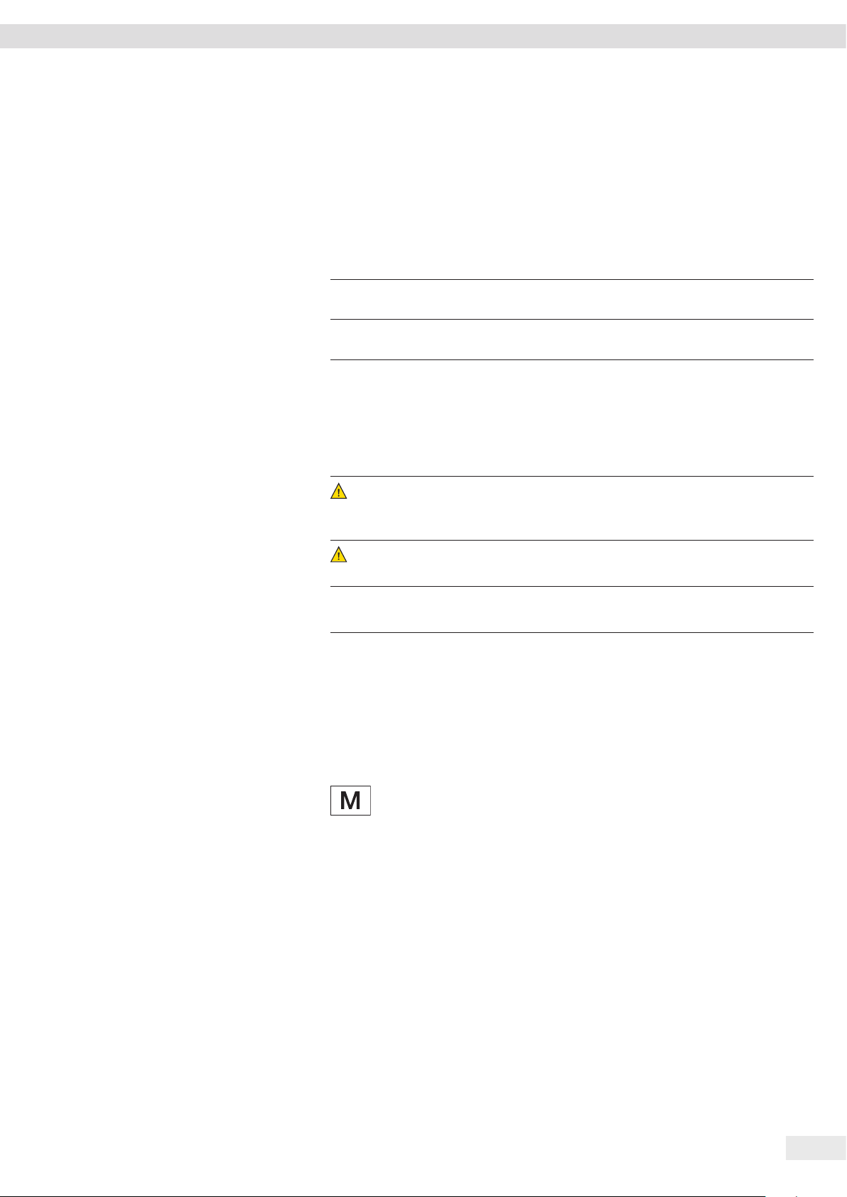
3.1 Device Overview
7
1
2
3
6
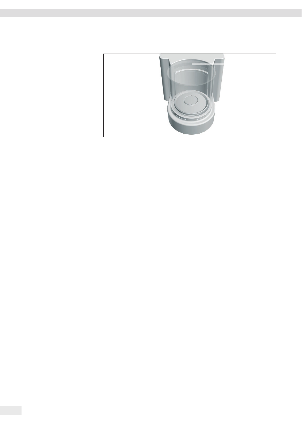
Fig. 1: Microbalance with glass draft shield and electronics module (example)
Pos. Designation Description
1 Leveling foot Motorically adjustable
2 Manufacturer’s ID label Not depicted
3 Electronics module
4 Operating display Touchscreen
5 Control unit
6 Weighing module
7 Weighing chamber
4
5
10 Cubis® MCE Operating Instructions
Page 11

3.2 Draft Shield
3
Device Description
4
1
2
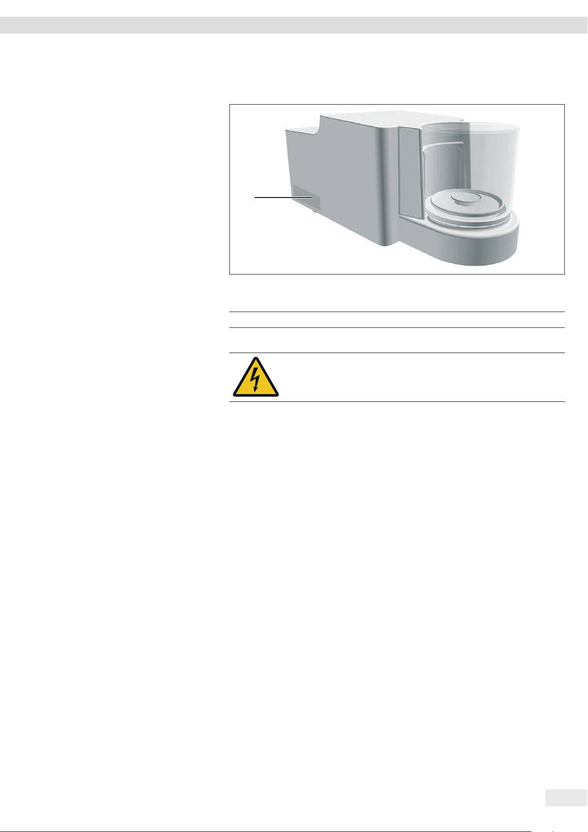
Fig. 2: Microbalance with motorized glass draft shield and filter microbalance with manual metal ring draft shield (example)
Pos. Designation Description
1 Metal ring draft shield cover Made from metal, with handle, can be removed.
2 Metal ring draft shield Consists of 2 metal rings that have been placed into each other with a side opening,
can be rotated manually.
3 Glass draft shield Made from glass, with side opening, motorized rotation. Can be removed.
4 Sensor window For the motion sensor, controls opening and closing of the motorized glass draft
shield
Cubis® MCE Operating Instructions 11
Page 12
Device Description
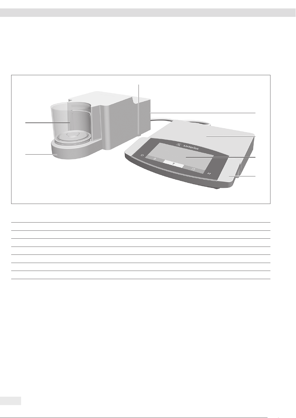
3.3 Weighing Pan and Associated Components
6
1
5
2
2
3
4
Fig. 3: Microbalance with glass draft shield and filter microbalance with metal ring draft shield (example)
3
4
Pos. Designation Description
1 Filter weighing pan
2 Shield plate
3 Connector For models MCE2.7S...F only
4 Pan retainer
5 Internal draft shield For models MCE2.7S...F only
6 Weighing pan
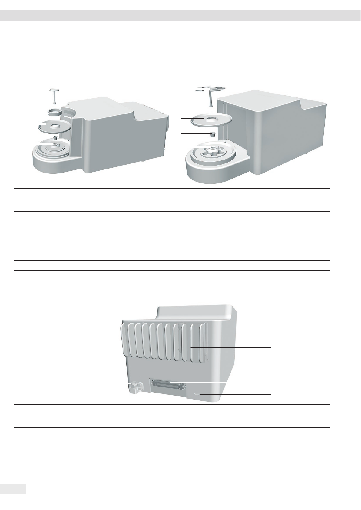
3.4 Connections and Components on the Backside of the Weighing Module
4
Fig. 4: Connections on the weighing module of the microbalance and filter microbalance (example)
Pos. Designation Description
1 Cooling fins For models MCE2.7S...F only
2 Electronics module connection For connecting the electronics module to the weighing module
3 Slot For the anti-theft device
4 Connection clamp For connection of a potential equalization
1
2
3
12 Cubis® MCE Operating Instructions
Page 13

Device Description
3.5 Connections on the Control Unit
Fig. 5: Connections on the control unit
Pos. Designation Description
1 USB connection Concealed, no function, for Sartorius Service only
1
3.6 Connections and Components on the Electronics Module
1 2 3 4 5
Fig. 6: Connections on the electronics module
Pos. Designation Description
1 On key Switches the device on from standby mode.
2 USB-A connection For printers and for software updates via a USB mass storage device
3 USB-B connection For connection to a PC
4 COM-RS232 connection 9-pin, for connection to a PC or PLC
5 Access switch Protects the device from changes to the device settings. Is sealed for conformity-
assessed devices.
6 Peripheral connection For connecting Sartorius accessories.
7 Weighing module connection For connecting the electronics module to the weighing module
8 Power supply For connection to the power supply
6
7
8
Cubis® MCE Operating Instructions 13
Page 14
Device Description
3.7 Displays on Weighing Module (Only for Microbalance)
1
Fig. 7: Displays on the weighing module (example)
Pos. Designation Description
1 LED strip Used for lighting of weighing chamber. The intensity of the
lighting can be adjusted in the menu. When the control unit
displays an error message: The LED strip is illuminated in
orange.
3.8 Motorized Draft Shield
3.8.1 Sensor Area
The device has a motion sensor that opens the draft shield automatically as soon as
a motion is detected within the sensor area. Following that the draft shield will be
automatically closed again. The operation is optimized for left- and right-handed
users due to the motion sensor.
The motion sensor sensitivity can be adjusted in steps (see Chapter “Parameters in
the “Motion Sensors” Submenu”, page 38)
3.8.2 Operating Elements for the Draft Shield
The draft shield can be opened and closed via the [Change] key. Operation via the
[Change] key enables the opening and closing of the draft shield as well as the
activation and deactivation of the motion sensor.
3.9 Conformity-assessed Devices
Some settings of conformity-assessed models are protected against user changes,
e.g. external calibration for devices in accuracy class II. This measure is intended to
ensure the suitability of the devices for use in legal metrology.
14 Cubis® MCE Operating Instructions
Page 15
Device Description
3.10 Symbols on the Device
1
Fig. 8: ID label on the device (example)
Pos. Designation Description
1 Manufacturer’s ID label Displays the metrological data of the device.
Symbol Meaning
During operation, parts in the device may be live. Only electricians
may have access to and work on these parts, such as for maintenance and repairs.
Cubis® MCE Operating Instructions 15
Page 16
Operating Concept
4 Operating Concept
4.1 Operating Display in Weighing Mode
21
3
6
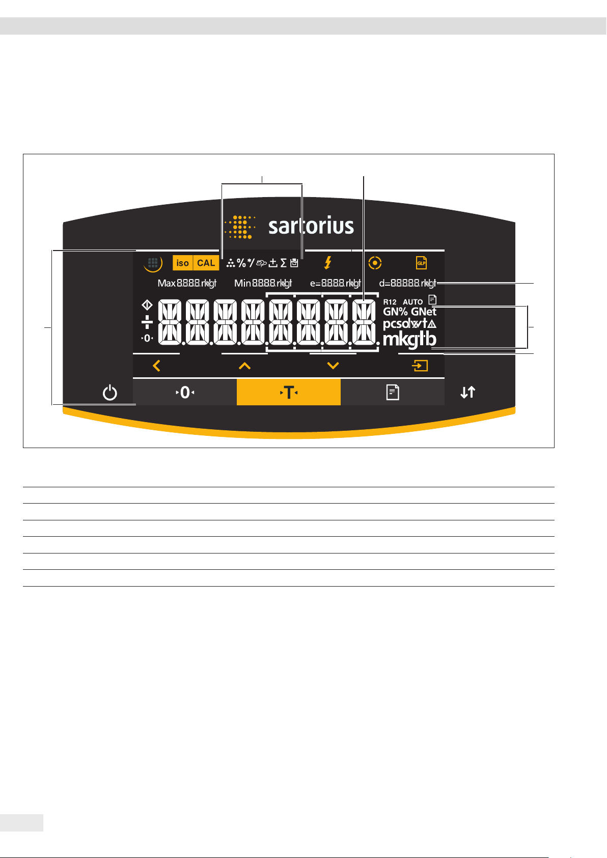
Fig. 1: Operating display in weighing mode (example)
Pos. Designation Description
1 Symbols for the selected application
2 Weight value display In the selected basic unit.
3 Metrological data
4 Weight units Shows the selected basic unit, e.g. grams, [g].
5 Visual touch-feedback Visual note on an active button or key.
6 Operating and display area
4
5
16 Cubis® MCE Operating Instructions
Page 17
4.2 Operating Display in the Menu
1 2 3 4
7
6
Operating Concept
5
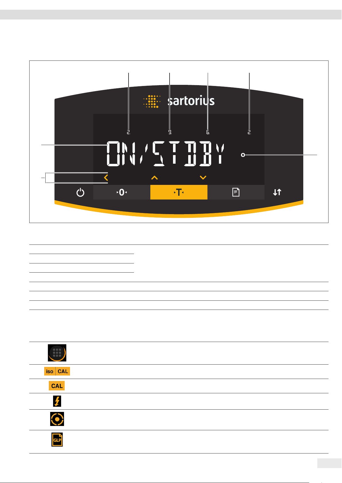
Fig. 2: Operating display in the menu (example)
Pos. Designation Description
1 Position in the 1st menu level Shows the position of the displayed menu or configuration value in up to 4 menu
2 Position in the 2nd menu level
levels.
3 Position in the 3rd menu level
4 Position in the 4th menu level
5 [Computed values] display Note on the set menu item
6 Operating area
7 Name of the menu or setting
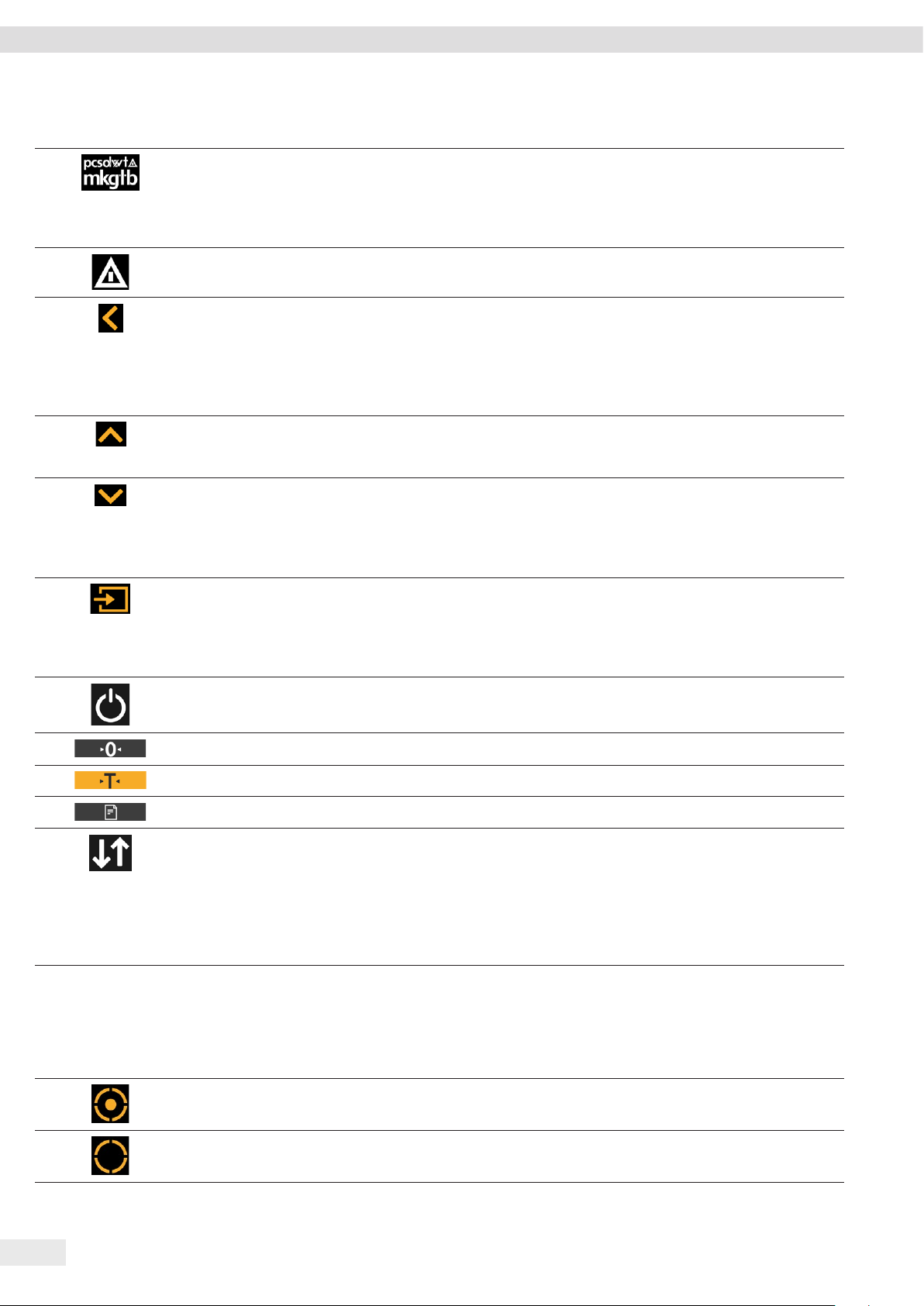
4.3 Buttons and Keys on the Operating Display
Pos. Symbol Designation Description
1
2
3
[Menu] button When the button is pressed: The settings menu opens.
If the button is held down: It switches to version display.
[isoCAL] button Starts the isoCAL function.
[Adjust] button Starts the set calibration and adjustment function.
4
5
6
[Ionizer] button Starts an ionization process.
[Leveling] button Starts a leveling process.
[GLP] button − Exits the GLP printout and starts printing the GLP footer.
− If the “Net-total”, “Totalizing”, or “Statistics” application is active: Prints and
deletes the saved values and exits the application.
Cubis® MCE Operating Instructions 17
Page 18
Operating Concept
Pos. Symbol Designation Description
7
8
[Toggle between weight
units] button
[Invalid weight value]
button
If the “Toggle between weight units” function is active:
− If the button is held down: Accesses the “Toggle between weight units” function
menu.
− When the button is pressed: Switches between the basic unit display and up to
4 other units.
If a fault exists in the weighing module: Indicates the cause of this fault.
9
10
11
12
13
14
[Back] button − In the menu:
− When the button is pressed: Returns to the previous display.
− If the button is held down: Saves the menu settings.
− When entering digits: Selects the previous digit position.
− For an active application: Exits the application and deletes the set reference
value.
[Up] button − In the menu: Scrolls through the menu levels or the available configuration
values.
− When entering digits: Increases the displayed value.
[Down] button − In the menu: Scrolls through the menu levels or the available configuration
values.
− When entering digits: Decreases the displayed value.
− In the main display of an active application: Accesses the display to set the
reference values.
[Confirm] button − In the menu: Accesses the displayed menu level or confirms the displayed
configuration value.
− When entering digits: Selects the next digit position.
− In the main display of an active application: Starts the application process and
saves the set reference value.
[On / Off] key If the key is briefly pressed: Switches the operating display on.
If the key is held down: Switches the operating display off.
[Zero] key Zeros the device.
15
16
17
[Tare] key Starts taring.
[Print] key Exports the readouts to the integrated data interfaces.
[Change] key − For models with a motorized draft shield: Opens or closes the doors on the draft
shield.
− For models without a motorized draft shield, if the “Toggle between weight
units” function is active:
− If the key is briefly pressed: Switches between the set weight units.
− If the key is held down: Accesses the “Toggle between weight units”
function menu.
4.4 Displays in the Operating Display
Pos. Symbol Designation Description
1
2
[Leveling] display − Indicates that the device is leveled.
− If the center circle is flashing: Indicates that the device is not leveled.
[Leveling] display Flashes while the device is leveling.
18 Cubis® MCE Operating Instructions
Page 19
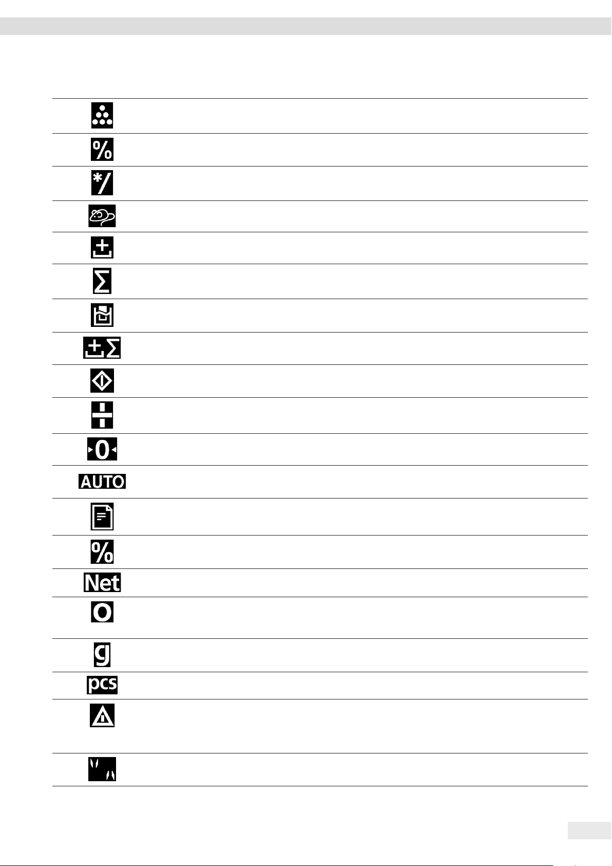
Pos. Symbol Designation Description
3
[Counting] display Indicates that the “Counting” application is selected.
Operating Concept
4
5
6
7
8
9
10
11
12
[Weighing in percent]
Indicates that the “Weighing in percent” application is selected.
display
[Calculation] display Indicates that the “Calculation” application is selected.
[Animal weighing]
Indicates that the “Animal weighing” application is selected.
display
[Net-total] display Indicates that the “Net-total” application is selected.
[Totalizing] display Indicates that the “Totalizing” application is selected.
[Density determination]
Indicates that the “Density determination” application is selected.
display
[Statistics] display Indicates that the “Statistics” application is selected.
[Busy] display Indicates that the device is processing a command.
[Sign] display Indicates whether the value being displayed is positive or negative.
13
14
15
16
17
18
19
20
21
22
[Zero] display For some conformity-assessed devices: Indicates that the device has been zeroed.
[AUTO] display Indicates that the “Animal weighing” application starts automatically.
[Data output] display Indicates that the data output is active.
[Percent] display Indicates that a percentage value is being displayed.
[Net] display Indicates that a net value is being displayed.
[Computed value]
display
− In the menu: Identifies the selected configuration value.
− If the “Calculation” or “Density determination” application is active: Indicates
that a calculated value is being displayed.
[Unit symbol] display Indicates the set weight unit, e.g. [g] for “grams”.
[Quantity] Indicates that a quantity is being displayed.
[Invalid weight value]
display
− Indicates that the display does not contain a weight value, rather it is the
calculated result of an application, e.g. for the “Totalizing” application.
− For conformity-assessed devices: Indicates a fault. The cause of this fault is
displayed after pressing the [Change] key.
[Directional arrows]
display
If leveling with the inclination sensor is active: Displays the direction of rotation of
the leveling foot.
Cubis® MCE Operating Instructions 19
Page 20

Operating Concept
4.5 Menu Structure
4.5.1 Overview of the Device Settings Menu
t Navigating in Menus (see Chapter 4.6, page 24).
Level 1 Level 2 Level 3 Description | Reference
SETUP BALANCE AMBIENT
“Ambient conditions”
APP FILT.
“Application filter”
STABIL.
“Stability range”
ST.DEL.
“Stability delay”
ZERO/TAR.
“Zeroing and taring”
AUTOZER.
“Auto zero”
UNIT Define the weight unit, e.g. grams, kilograms, pounds.
DISP.DIG. Define whether all decimal places are displayed. A lower
CAL./ADJ.
“Adjust”
CAL.SEQ.
“Calibration sequence”
ZERORNGE
“Zero range”
INI.ZERO.R
“Zero at power on”
ON Z/T
Tare / zero at power on
CYC.RATE
“Output rate”
Enter the ambient conditions at the device’s installation
site.
Equalize the load deviations in the display. The load
deviations occur between the complete placement of the
sample on the weighing pan and reaching the final result
display.
Define the accuracy of the stability range. If the weight
unit symbol appears, the weight readout is stable within
the range indicated by the stability range
Define the duration of the stability delay. The stability
delay is used to bridge residual fluctuations in the vibration
of the device in order to display reliable results.
Define the trigger for zeroing and taring.
Activate / deactivate automatic control of the zero display.
The deviations of a set fraction of scale intervals per
second starting from the display zero point are
automatically zeroed.
Depending on the country-specific model version, not all
weight units listed may be available. Some weight units
may be blocked from use in conformity-assessed devices,
depending on national verification laws.
display accuracy enables a faster display. The setting option
is not available on conformity-assessed devices.
Define the function of the [Adjust] button.
Define the sequence of the “Calibrate and adjust” function.
Define the zero range of the device.
Define the zero range when switching on the device.
Activate / deactivate automatic taring when starting the
device.
Determine the data output rate.
20 Cubis® MCE Operating Instructions
Page 21

Operating Concept
Level 1 Level 2 Level 3 Description | Reference
ISOCAL Configure the isoCAL function.
EXT.CAL.
“External adjustment”
CAL.UNIT
Configure the function “External calibration and
adjustment”.
Define the weight unit for the calibration weight.
“Calibration weight unit”
GEN.SERV.
“General services”
DEVICE RS232
MEN.RESET
Reset the menu to factory settings.
“Menu reset”
DAT.REC. Set the communication protocol for the connected device.
“COM-RS232, 9-pin”
BAUD Set the baud rate for the connected device.
PARITY Set the parity for the connected device.
STOPBIT Set the number of stop bits.
HANDSHK. Set the handshake between the balance and the device.
DATABIT Set the number of data bits.
PC-USB
DAT.REC. Set the communication protocol for the connected PC.
“USB-B (Device/
Slave)”
BAUD Set the baud rate for the connected PC.
PARITY Set the parity for the connected PC.
STOPBIT Set the number of stop bits.
HANDSHK. Set the handshake between the device and the connected
PC.
DATABIT Set the number of data bits.
USB
“USB-A (Host/Master)”
D.SHIELD
DEV.USED
Display the device connected via USB-A.
“Device in use”
CONTROL Activate / deactivate the motorized draft shield.
“Draft shield”
Only for devices with
a motorized draft
shield.
INT.ADJ. Define the function of the draft shield when starting an
internal adjustment.
SEN.L.MOT. Set the sensitivity of the left motion sensor.
ACT.L.MOT. Define the action for the left motion sensor.
SEN.R.MOT. Set the sensitivity of the right motion sensor.
ACT.S.MOT. Define the action for right motion sensor.
LIGHTING Set the brightness of the lighting of the draft shield.
LEVELING
“Leveling”
LEVEL Define the settings for the integrated inclination sensor.
START Define the trigger for automatic leveling.
Cubis® MCE Operating Instructions 21
Page 22

Operating Concept
Level 1 Level 2 Level 3 Description | Reference
MOTION.S.
CONTROL Activate / deactivate the motion sensor.
“Motion sensor”
NUM.GEST.
Define the number of possible gestures.
“Number”
LEFT CMD. Define the function for the left gesture.
RIGHT.CMD. Define the function for the right gesture.
UP.CMD. Define the function for the up gesture.
DOWN.CMD. Define the function for the down gesture.
EXTRAS MENU Lock or unlock the menu’s configuration parameters.
SIGNAL Set or deactivate the acoustic signal.
KEYS Activate / deactivate the key lock.
ON MODE
“Switch-on and
Configure the device’s switch-on and switch-off options,
e.g. switch between standby mode and operating mode.
switch-off options”
LIGHTING Activate / deactivate the lighting for the operating display.
DATA.OUTP.
“Data output”
COM. SBI
“SBI communication”
COM.OUTP. Configure the automatic data output.
STOP.AUTO Define whether the automatic data output can be stopped
and started with the [Print] key.
AUTO.CYCL.
“Time-dependent
interval”
− Define an interval for the automatic data output.
− Define whether data output takes place after an
interval with or without balance stability.
FORMAT Define the data output format (characters per line).
AUTO.TARE Activate / deactivate automatic taring after the printout.
PRNT.PARA.
“Printout settings”
ACTIVATE
“Triggers”
Define whether a printout is triggered via a software
command or using the [Print] key.
FORMAT Define the format for the printout (characters per line).
PRT.INIT.
Define the settings for printer initialization.
“Initializing”
GLP Define the settings for the GLP printout.
TAR./PRT.
“Tare / print”
Activate / deactivate automatic taring after every print
process.
TIME Define the time format.
DATE Define the date display format.
PC.DIRECT
DEC.SEPAR. Define the decimal separator character.
Direct transfer of data
(PC)
OUTP.FORM. Define the output format for the data exchange between
the balance and the PC.
APPLIC.
“Applications”
WEIGH
(Factory setting)
UNIT Activate / deactivate the “Toggle between weight units”
function for all applications.
COUNT RESOLUT. Define the resolution of the weight value for the
“Counting” application.
REF.UPDT.
“Reference updating”
Activate / deactivate automatic reference updating for the
“Counting” application.
22 Cubis® MCE Operating Instructions
Page 23

Operating Concept
Level 1 Level 2 Level 3 Description | Reference
PERCENT
“Weighing in percent”
NET-TOTL.
“Net-total”
TOTAL
“Totalizing”
ANIMALW.
“Animal weighing”
DEC.PLCS
“Decimal places”
COMP.PRT.
“Component printout”
COMP.PRT.
“Component printout”
ACTIVITY
“Animal activity”
Define the number of decimal places for the “Weighing in
percent” application.
Activate / deactivate the component printout for the “Nettotal” application.
Activate / deactivate the component printout for the
“Totalizing” application.
Define the level of activity of the sample for the “Animal
weighing” application.
START Define the trigger for starting the animal weighing.
CALC.
“Calculation”
DENSITY
“Density
METHOD Define the method of calculation for the “Calculation”
application.
DEC.PLCS
“Decimal places”
DEC.PLCS
“Decimal places”
Define the number of decimal places for the “Calculation”
application.
Define the number of decimal places for the “Density
determination” application.
determination”
STATIST.
“Statistics”
COMP.PRT.
“Component printout”
TAR./STAT.
“Tare/statistics”
Activate / deactivate the component printout for the
“Statistics” application.
Activate / deactivate automatic taring for the “Statistics”
application.
UPDATE Start a firmware update. The menu is only available if a
USB mass storage device is connected.
INPUT ID NO. Save the entered ID number for the device.
LOT ID Activate / deactivate the prompt of the lot ID number
before every data output.
DATE Set the date.
TIME Set the time.
USER.PASS. Set the user password.
DEL.PASS. Delete the user password. The menu is only available if a
user password is set.
SERV.PASS. Activate the service mode.
CAL.WT.
Define the value of the external user calibration weight.
“Calibration weight”
INFO
“Device
VERSION
“Version number”
Display the software version number.
information”
SER. NO.
Display the device’s serial number.
“Serial number”
MODEL Display the device’s model ID.
APC VER. Display the version of the APC processor.
BAC VER. Display the version of the BAC processor.
MCU VER. Display the version of the MCU processor.
WPC VER.
Display the draft shield software version.
“Draft shield version”
LANGUAGE Change the menu language.
Cubis® MCE Operating Instructions 23
Page 24
Operating Concept
Overview of the “Toggle between weight units” Function
t Navigating in Menus (see Chapter 4.6, page 24).
Level 1 Description
Unit 1 Define the displayed weight unit and the resolution for the 1st convertible unit.
Unit 2 Define the displayed weight unit and the resolution for the 2nd convertible unit.
Unit 3 Define the displayed weight unit and the resolution for the 3rd convertible unit.
Unit 4 Define the displayed weight unit and the resolution for the 4th convertible unit.
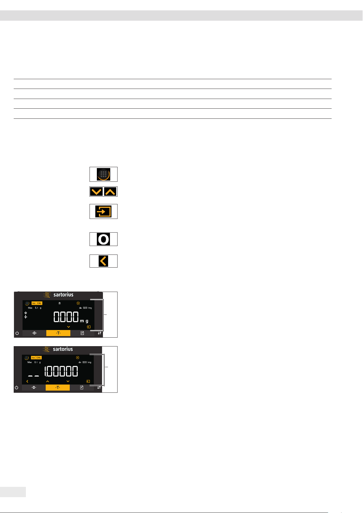
4.6 Navigating the Menus
Procedure
t To access the settings menu: Press the [Menu] button.
t To scroll through all menus in the same level: Press the [Up] or [Down] button.
t To switch to the displayed menu level: Press the [Confirm] button on the keypad.
t To scroll through the configuration values: Press the [Up] or [Down] button.
t To select the configuration value shown in the display or the displayed
application: Press the [Confirm] button on the keypad.
y The [Value] display identifies the selected configuration value or the selected
application.
t To return to the next higher menu level: Press the [Back] button.
t To exit the settings menu: In the main menu level, press the [Back] button.
t If the start display (1) of a selected application is displayed:
t To start the application without changing the preset reference value: Press
the [Confirm] button on the keypad.
1
t To change a reference value before starting the application, e.g. density value,
divisor or reference quantity: Press the [Up] button.
y The reference value display is shown for the selected application.
t If a reference value with decimal places needs to be selected in the reference
value display (1) of a selected application, e.g. “Density determination” or
1
“Calculation” applications:
y The selected digit position flashes.
t Use the [Up] or [Down] button to change the value for the selected digit
position.
t If a digit position other than the last digit position is selected: Press the
[Confirm] button to select the next digit position.
t If a digit position other than the first digit position is selected: Press the
[Back] button to select the previous digit position.
t If the last digit position is selected: Press the [Confirm] button to save the
displayed reference value and start the application process.
t If the first digit position is selected: Press the [Back] button to delete the
displayed reference value and return to the application’s status display.
24 Cubis® MCE Operating Instructions
Page 25

Operating Concept
t If an integer reference value needs to be selected in the reference value display
(1) of a selected application, e.g. “Weighing in percent” or “Animal weighing”
1
applications:
t Press the [Up] or [Down] button. This increases or decreases the reference
value by 1.
t Hold down the [Up] or [Down] button. This increases or decreases the
reference value by 10.
t To start the application: Press the [Confirm] button on the keypad.
t To delete the displayed reference value and return to the application’s status
display: Press the [Back] button.
t If the results display (1) of a selected application is displayed:
t To switch between the application results display and the set reference value
1
display: Press the [Up] or [Down] button.
t To exit the results, display and delete the set reference value and the result of
the application: Press the [Back] button.
Cubis® MCE Operating Instructions 25
Page 26

Installation
5 Installation
5.1 Scope of Delivery
Item Quantity
Device 1
Weighing pan 1
For filter ultramicrobalances and microbalances: Filter weighing pan 1
For model MCA2.7S…: Shield disk 1
For model MCA2.7S…: Internal draft shield 1
Shield plate 1
Pan support 1
Power supply unit 1
Country-specific power supply cable with test seal 1
USB connection cable 1
In-use dust cover for control unit 1
In-use dust cover for the weighing module 1
Electronics module with power supply cable 1
Connection cable for electronics module 1
5.2 Selecting an Installation Site
Procedure
t Ensure that the following conditions are met at the installation site:
Condition Features
Ambient conditions Suitability tested (see Chapter “15.6 Ambient
Conditions”, page 67)
Setup surface Stable, even surface that is not exposed to
vibrations
Not directly against a wall
Sufficiently dimensioned for the device and the
peripheral devices (device space requirements see
Chapter “15.1 Dimensions and Weight”, page 65;
peripheral device space requirements see instructions for the peripheral devices, e.g. printer)
Sufficient load-bearing capacity for the device
and the peripheral devices even when full (device
weight see Chapter “15.1 Dimensions and Weight”,
page 65; weight of the peripheral devices see
instructions for the peripheral devices, e.g. printer)
Access Barrier-free
26 Cubis® MCE Operating Instructions
Page 27

Installation
5.3 Unpacking the Device
Procedure
t Lift the device in the Styrofoam padding out of the packaging.
t Place the device in the Styrofoam padding on its side.
t Lift the Styrofoam padding off the device.
t NOTICE Glass breakage due to the incorrect handling of the device! Only lift the
device by its base.
t Place the device on its base.
t Keep all parts of the original packaging, e.g. to return the device.
5.4 Preparing Below-cell Weighing
The device can be configured for below-balance weighing. Samples can be
suspended for weighing using below-balance weighing, e.g. samples, which do not
fit on the weighing pan.
For below-balance weighing, the cover plate must be removed and the device set up
on a weighing table with recess.
In legal metrology:
− Do not use the below-cell weighing equipment.
− Do not open the cover of the below-cell weighing equipment.
Tool: 1 Torx Allen key, T20
Material: 1 soft support base
1 draft protection shield
1 weighing table with recess
Requirements
− The draft shield has not been mounted.
− The weighing pan and the associated components have not been set up.
Procedure
t Turn the device on its side and place it on the soft support base.
Cubis® MCE Operating Instructions 27
Page 28

Installation
2
t Unscrew both screws (2) from beneath the weighing module with the 1 Torx
Allen key.
1
t Lift out the cover plate (1).
t Install a draft protection shield.
3
t Set up the device on the weighing table with recess. The hook for below-balance
weighing (3) may not touch the weighing table.
t Install the draft protection shield.
t To cover the below-balance weighing equipment after weighing:
t Insert cover plate and screw on with both screws.
t Place the device back on the device base on a level surface.
28 Cubis® MCE Operating Instructions
Page 29

Installation
5.5 Installing a Microbalance with Glass Draft Shield
5.5.1 Positioning the Weighing Pan and Associated Components
Procedure
t For a device with a connector: Place the connector (2) on the base of the
weighing chamber.
t Place the shield plate (1) on the base of the weighing chamber.
1
2
t Place the weighing pan (1) through the opening in the weighing chamber into
the pan retainer.
t To mount the weighing pan: Turn the weighing pan slightly while pressing down
lightly.
1
t For devices with an internal draft shield: Place the internal draft shield on a
shield plate.
t Center and insert glass draft shield with recess (1) above the snap-in peg (2).
1
2
Cubis® MCE Operating Instructions 29
Page 30

Installation
5.6 Installing a Filter Microbalance with a Metal Ring Draft Shield
5.6.1 Inserting a Filter Pan or Weighing Pan and Associated Components
Procedure
t For a device with a connector: Place the connector on the base of the weighing
chamber.
t Place the shield plate (2) on the base of the weighing chamber.
t Place the draft shield (1) on the base of the weighing chamber. The inner metal
1
2
ring of the draft shield must be inserted into the outer metal ring.
t Turn the opening of the draft shield in the direction of the arrows.
t To mount the draft shield: Turn the screw (2).
1
2
1
t Place the filter pan (1) or the weighing pan through the opening in the shield
plate on the pan retainer.
t BEWARE The filter pan or weighing pan can be damaged due to improper
assembly. To mount the inserted filter pan or weighing pan: Screw in the filter
pan or weighing pan with slight pressure to make correctly position it in the pan
retainer.
t Insert the pin (1) in the draft shield cover into the recess of the draft shield and
screw on draft shield cover onto draft shield.
30 Cubis® MCE Operating Instructions
Page 31

Installation
5.6.2 Optimizing a Filter Weighing Pan with a Metal Ring Draft Shield for Left-handed Users
Requirements
The metal ring draft shield has been mounted.
Procedure
t Lift the draft shield cover from the draft shield and turn.
t Unscrew bearing pin (1) from the underside of the draft shield cover and screw
1
into the opening of the opposite side.
t Place the wind shield cover on wind shield.
t Loosen screw (1) on draft shield and turn draft shield in the direction of the
arrows by 90°.
t Retighten the screw.
1
5.7 Connecting the Electronics Module
Procedure
t Connect the connection cable to the electronics module’s weighing module
connection.
t Connect the other end of the connection cable to the weighing module
electronics module connection.
t To lock the connection cable: Lock the plugs of the connection cable onto both
connections with two clicks in each case.
t NOTICE Damage to the device due to incorrect connection!
t Check the correct fit of the plug contacts.
t There should be no tension on the connection cable, e.g. do not install
directly against a wall.
5.8 Acclimatization
When a cold device is brought into a warmer area: The temperature difference can
lead to condensation of humidity in the device (moisture formation). Moisture in the
device can lead to malfunctions.
t Allow the device to acclimatize for approx. 2 hours at the installation site.
Ensure that the device is disconnected from the power supply during that time.
Cubis® MCE Operating Instructions 31
Page 32

Getting Started
6 Getting Started
6.1 Connecting Electronic Components
Procedure
t NOTICE Improper connection may damage the device! If the device is connected
using electronic components, e.g. printer, PC: The device must be disconnected
from the power supply. Ensure that the device is disconnected from the power
supply.
t Connect the device using electronic components (see electronic components
instructions).
6.2 Installing the AC Adapter
Procedure
t Plug the DC supply cable of the AC adapter into the electronics module’s “power
supply” connection socket and tighten the threaded fitting.
t Connect the power supply cable to the AC adapter connection.
6.3 Connecting the Power Supply
Procedure
t
WARNING Severe injuries caused by using a defective power supply cable!
Check the power supply cable for damage, e.g., cracks in the insulation.
t If required: Contact Sartorius Service.
t Check whether the country-specific power plug matches the power connections
at the installation site.
t If required: Contact Sartorius Service.
t NOTICE Damage to the device due to excessive input voltage! Check whether the
voltage specifications on the AC adapter match those of the power supply at the
installation site.
t If the input voltage is too high: Do not connect the device to the power
supply.
t Contact Sartorius Service.
t Connect the mains plug of the power supply cable to the wall outlet at
the installation site.
y The [BOOTING] display appears in the operating display.
y The device performs a self-test.
y The device performs an initial tare function.
32 Cubis® MCE Operating Instructions
Page 33

System Settings
7 System Settings
7.1 Performing System Settings
Default settings can be adjusted for the device and the applications in order to align
with the ambient conditions and individual operating requirements.
The following settings are necessary to operate the device together with connected
components:
− Set up the communication of the connected devices
− Set up additional components
The following settings are recommended to set up the device:
− Set the menu language
− Set the behavior of the isoCAL function
− Set the behavior of the motorized draft shield (only for devices with a motorized
draft shield)
Procedure
t Press the [Menu] button.
t Open the desired settings menu.
t To adjust settings: Open the desired main menu and submenu.
t Select and confirm the desired configuration value (configuration values, see
Chapter “7.3 Parameter List”, page 34).
t Exit the menu.
y If settings have been adjusted in the “SETUP”, “DEVICE”, “DATA.OUTP.” or
“APPLIC.” menu: The [BOOTING] display appears in the operating display and the
device restarts.
7.2 Switching Off the isoCAL Function
If the isoCAL function is switched off for a conformity-assessed device, the device
can only be used for legal-for-trade applications in restricted temperature ranges
(see Chapter “15.6.2 Ambient Temperature for the isoCAL Function”, page 67). The
isoCAL function cannot be switched off for all model versions.
Procedure
t In the “SETUP” / “BALANCE” menu, for the “ISOCAL” parameter, select the “OFF”
configuration value.
Cubis® MCE Operating Instructions 33
Page 34

System Settings
7.3 Parameter List
7.3.1 Parameters in the “Setup” Main Menu
Parameters in the “Balance” Submenu
Parameters Setting values Explanation
AMBIENT V.STABLE Sets the ambient conditions to “very stable”: Activates a fast change in the weight values
in the event of a load change with a high output rate.
Recommended for the following work environment:
− Very stable table near the wall
− Closed and calm room
STABLE* Sets the ambient conditions to “stable”.
Recommended for the following work environment:
− Stable table
− Slight movement in the room
− Slight draft
UNSTABL. Sets the ambient conditions to “unstable”: Activates the delayed change in weight values
with a reduced output rate.
Recommended for the following work environment:
− Simple office desk
− Room with moving machinery or personnel
− Slight air movement
V.UNSTBL. Sets the ambient conditions to “very unstable”: Activates a significantly delayed change
in the weight values and long wait for stability with a further reduction in the output
rate.
Recommended for the following work environment:
− Noticeable and slow floor vibrations
− Noticeable building vibrations
− Weighed goods moved
− Very strong air movements
APP FILT. FINAL.RD.* Activates a filter that enables a fast change in the display for very fast load changes.
Display changes with minimal load changes (in the digit range) occur more slowly.
FILLING Activates a filter that enables a very fast change in the display with minimal load
changes (e.g. when filling containers).
REDUC. Activates a weak but fast filter that always behaves in the same way for load changes
(e.g. when filling automated systems).
OFF Deactivates the active application filter.
STABIL. MAX ACC. Sets the stability to “maximum accuracy”.
V. ACC. Sets the stability to “very accurate”.
ACC.* Sets the stability to “accurate”.
FAST Sets the stability to “fast”.
V. FAST Sets the stability to “very fast”.
MAX.SPEED Sets the stability to “maximum speed”.
ST.DEL. NONE Sets the stability delay to “none”: The stability symbol is displayed after the stability
criterion is reached.
SHORT* Sets the stability delay to “short”: The stability symbol only appears after a short delay in
order to provide a reliable result despite fluctuations.
* Factory setting
34 Cubis® MCE Operating Instructions
Page 35

System Settings
Parameters Setting values Explanation
MEDIUM Sets the stability delay to “medium”: The stability symbol only appears after a longer
delay in order to provide a reliable result in case of higher fluctuations.
LONG Sets the stability delay to “long”: The stability symbol only appears after a long delay in
order to balance out major instability.
ZERO/TAR. W/O STB. Without stability: The function of the [Zero] or [Tare] key is executed immediately once
the key is pressed.
W/ STAB.* With stability: The function of the [Zero] or [Tare] key is only executed after stability is
achieved.
AT STAB. At stability: The function of the [Zero] or [Tare] key is executed if stability exists when
the key is pressed.
AUTOZER. ON* Activates automatic zeroing. The display is automatically set to zero in case of a
deviation of 0 less than (X).
OFF Deactivates automatic zeroing. Zeroing must be triggered with the [Zero] key.
UNIT The availability of units may depend on national legislation and is therefore country-
specific.
GRAMS* The device displays the weight in grams.
KILOGR. The device displays the weight in kilograms (not for semi-microbalances).
CARATS The device displays the weight in carats.
POUNDS The device displays the weight in pounds (not for semi-microbalances).
OUNCES The device displays the weight in ounces.
TROY OZ. The device displays the weight in troy ounces.
HKTAEL The device displays the weight in taels (Hong Kong).
SNGTAEL The device displays the weight in taels (Singapore).
TWNTAEL The device displays the weight in taels (Taiwan).
GRAINS The device displays the weight in grains.
PENYWT. The device displays the weight in pennyweights.
MILLIGR. The device displays the weight in milligrams.
CHINATAEL The device displays the weight in taels (China).
MOMMES The device displays the weight in mommes.
TOLA The device displays the weight in tolas.
BAHT The device displays the weight in baht.
MESGHAL The device displays the weight in mesghals.
NEWTON The device displays the weight in newtons.
DISP.DIG. ALL* “Show all decimal places”: All decimal places are shown in the display. Not available on
conformity-assessed devices.
LP.ON/OFF “Reduced by 1 decimal place for load change”:
The last decimal place on the display is switched off until stability is achieved.
DIVIS. 1 “Last decimal place of the 1st division”: The last decimal place always shows the 1st
division.
MINUS 1 “Last decimal place off”: The last decimal place is switched off.
* Factory setting
Cubis® MCE Operating Instructions 35
Page 36

System Settings
Parameters Setting values Explanation
CAL./ADJ. EXT.CAL. The [Adjust] button starts an external calibration with the preset calibration weight.
E.CAL.USR. The [Adjust] button starts an external calibration with the user-defined calibration
weight value.
INT.CAL.* The [Adjust] button starts an internal calibration.
INT.LIN. The [Adjust] button linearizes the balance with the integrated weight (not for precision
balance)
CAL.SEQ. ADJUST* Calibration and adjustment is one routine.
CAL.-ADJ. Adjustment must be started or exited manually after calibration with the [Adjust]
button.
ON Z/T ON* Activates the initial taring / zeroing. The device is tared or zeroed after it is switched on.
OFF Deactivates the initial taring / zeroing: After it is switched on, the device shows the value
before it was last switched off.
ISOCAL OFF Switches the isoCAL function off.
NOTE TO The [isoCAL] button flashes if the balance needs to be adjusted. The isoCAL function
must be manually triggered with the [Adjust] button.
ON* Activates the isoCAL function. The device is automatically adjusted as soon as a trigger
starts the isoCAL function.
ON W/LIN.
(only for semi-
Activates the isoCAL and linearization function. The device is automatically adjusted and
then linearized as soon as a trigger starts the isoCAL function.
microbalances
and analytical
balances)
CAL.UNIT GRAMS* Changes the calibration weight unit to grams.
KILOGR. Changes the calibration weight unit to kilograms.
* Factory setting
Parameters in the “General Services” Submenu
Parameters Setting values Explanation
MEN.RESET YES Resets the system settings to the factory default settings.
NO* Deactivates the option of resetting the device menu.
* Factory setting
7.3.2 Parameters in the “Device” Main Menu
Parameters in the “Extras” Submenu
Parameters Setting values Explanation
MENU EDITABLE* Activates write access: The menu parameters can be changed.
RD.ONLY Activates read access: The menu parameters cannot be changed.
SIGNAL OFF Switches the acoustic signal off.
QUIET Sets the volume of the acoustic signal to “quiet”.
MEDIUM* Sets the volume of the acoustic signal to “medium”.
LOUD Sets the volume of the acoustic signal to “loud”.
KEYS UNLOCKED* Deactivates the key lock.
LOCKED Activates the key lock.
* Factory setting
36 Cubis® MCE Operating Instructions
Page 37

System Settings
Parameters Setting values Explanation
ON MODE ON/STDBY* The [On / Off] key switches between on / standby.
ON/OFF The [On / Off] key switches between on / off.
AUTO ON Changes the function of the [On / Off] key: The device no longer switches off or to
standby mode, instead it starts a boot process.
LIGHTING OFF Deactivates the lighting on the operating display.
ON* Activates the lighting on the operating display.
* Factory setting
Parameters in the “Draft Shield” Submenu (Only for Devices with a Motorized Draft Shield)
Parameters Setting values Explanation
CONTROL OFF Deactivates the motorized draft shield.
ON* Activates the motorized draft shield.
INT.ADJ. NONE The draft shield does not perform an action if an internal calibration / adjustment
starts.
CLOSE* Draft shield closes if an internal calibration / adjustment starts.
SEN.L.MOT. OFF* Deactivates the left motion sensor of the gesture control for the draft shield.
LOW Sets the sensitivity of the left motion sensor of the gesture control to “low”.
MEDIUM* Sets the sensitivity of the left motion sensor of the gesture control to “medium”.
HIGH Sets the sensitivity of the left motion sensor of the gesture control to “high”
ACT.L.MOT. OWN SITE* The own (left) site of the draft shield is controlled by the left motion sensor of the
gesture control.
OPPOSITE The opposite (right) site of the draft shield is controlled by the left motion sensor of
the gesture control.
SEN.R.MOT. OFF Deactivates the right motion sensor of the gesture control for the draft shield.
LOW Sets the sensitivity of the right motion sensor of the gesture control to “low”.
MEDIUM* Sets the sensitivity of the right motion sensor of the gesture control to “medium”.
HIGH Sets the sensitivity of the right motion sensor of the gesture control to “high”
ACT.S.MOT. OWN SITE* The own (right) site of the draft shield is controlled by the right motion sensor of the
gesture control.
OPPOSITE The opposite (left) site of the draft shield is controlled by the right motion sensor of
the gesture control.
LIGHTING OFF Deactivates the lighting on the draft shield.
DARK Sets the brightness of the lighting of the draft shield to “dark”.
MEDIUM* Sets the brightness of the lighting of the draft shield to “medium”.
BRIGHT Sets the brightness of the lighting of the draft shield to “bright”.
* Factory setting
Cubis® MCE Operating Instructions 37
Page 38

System Settings
Parameters in the “Leveling” Submenu
Parameters Setting values Explanation
LEVEL OFF The device does not display messages on the status of the level.
NOTE* The [LEVELING] display flashes if the device needs to be leveled.
ERR.MSG. The [LEVEL.ERR.] message appears in the operating display if the device has not been
leveled.
START KEY Sets the trigger for leveling to “key”: Leveling must be started manually by pressing
the [Leveling] button.
AUTO* Sets the trigger for leveling to “automatic”: The device automatically performs a
leveling function using the integrated sensor before every internal
calibration / adjustment.
* Factory setting
Parameters in the “Motion Sensors” Submenu
Parameters Setting values Explanation
CONTROL OFF Deactivates the motion sensor: No gestures are recognized.
ON* Activates the motion sensor.
NUM.GEST. 2 GESTUR.* Activates the control of functions with 2 gestures. Gestures: Left, right
4 GESTUR. Activates the control of functions with 4 gestures. Gestures: Left, right, top, bottom
LEFT CMD. PRINT* Left command of the gesture control corresponds to the [Print] key.
ZERO Left command of the gesture control corresponds to the [Zero] key.
TARE Left command of the gesture control corresponds to the [Tare] key.
D.SHIELD Left command of the gesture control corresponds to the [Change] key.
OPEN LFT. Left command of the gesture control opens the left draft shield panel.
OPEN RT. Left command of the gesture control opens the right draft shield panel.
OPEN TOP Left command of the gesture control opens the upper draft shield panel.
CLOSE DS. Left command of the gesture control closes the entire draft shield.
NONE No function is assigned to the left command of the gesture control.
RIGHT.CMD. PRINT* Right command of the gesture control corresponds to the [Print] key.
ZERO Right command of the gesture control corresponds to the [Zero] key.
TARE Right command of the gesture control corresponds to the [Tare] key.
D.SHIELD Right command of the gesture control corresponds to the [Change] key.
OPEN LFT. Right command of the gesture control opens the left draft shield panel.
OPEN RT. Right command of the gesture control opens the right draft shield panel.
OPEN TOP Right command of the gesture control opens the upper draft shield panel.
CLOSE DS. Right command of the gesture control closes the entire draft shield.
NONE No function is assigned to the right command of the gesture control.
UP.CMD. PRINT* Upper command of the gesture control corresponds to the [Print] key.
ZERO Upper command of the gesture control corresponds to the [Zero] key.
TARE Upper command of the gesture control corresponds to the [Tare] key.
D.SHIELD Upper command of the gesture control corresponds to the [Change] key.
OPEN LFT. Upper command of the gesture control opens the left draft shield panel.
OPEN RT. Upper command of the gesture control opens the right draft shield panel.
OPEN TOP Upper command of the gesture control opens the upper draft shield panel.
CLOSE DS. Upper command of the gesture control closes the entire draft shield.
NONE No function is assigned to the upper command of the gesture control.
* Factory setting
38 Cubis® MCE Operating Instructions
Page 39

System Settings
Parameters Setting values Explanation
DOWN.CMD. PRINT* Lower command of the gesture control corresponds to the [Print] key.
ZERO Lower command of the gesture control corresponds to the [Zero] key.
TARE Lower command of the gesture control corresponds to the [Tare] key.
D.SHIELD Lower command of the gesture control corresponds to the [Change] key.
OPEN LFT. Lower command of the gesture control opens the left draft shield panel.
OPEN RT. Lower command of the gesture control opens the right draft shield panel.
OPEN TOP Lower command of the gesture control opens the upper draft shield panel.
CLOSE DS. Lower command of the gesture control closes the entire draft shield.
NONE No function is assigned to the lower command of the gesture control.
* Factory setting
Parameters in the “COM-RS232” Submenu
Parameters Setting values Explanations
DAT.REC. SBI.WEIGH. Enables a faster SBI communication, only for software commands to the weighing
module.
XBPI Extended range of commands to control numerous balance functions with binary
protocol for direct communication with the weighing module.
SBI* Enables SBI communication. The data is output to a PC or control unit. Enables the
use of ESC commands from a PC to control the basic balance functions with ASCII
protocol.
OFF Deactivates the automatic data output.
BAUD 600 Sets the baud rate to 600 baud.
1200 Sets the baud rate to 1200 baud.
2400 Sets the baud rate to 2400 baud.
4800 Sets the baud rate to 4800 baud.
9600* Sets the baud rate to 9600 baud.
19200 Sets the baud rate to 19200 baud.
38400 Sets the baud rate to 38400 baud.
57600 Sets the baud rate to 57600 baud.
115200 Sets the baud rate to 115200 baud.
PARITY ODD* Applies an odd parity.
EVEN Applies an even parity.
NONE Does not apply a parity.
STOPBIT 1 BIT* Sets the number of stop bits to 1.
2 BITS Sets the number of stop bits to 2.
HANDSHK. SOFTWARE Sets the handshake protocol to software handshake.
HARDWARE* Sets the handshake protocol to hardware handshake.
NONE Does not set a handshake protocol.
DATABIT 7 BITS Sets the number of data bits to 7.
8 BITS* Sets the number of data bits to 8.
* Factory setting
Cubis® MCE Operating Instructions 39
Page 40

System Settings
Parameters in the “PC-USB” Submenu
Parameters Setting values Explanations
DAT.REC. SBI.WEIGH. Enables a faster SBI communication, only for software commands to the weighing
module.
XBPI Extended range of commands to control numerous balance functions with binary
protocol.
SBI* Enables SBI communication. The data is output to a PC or control unit. Enables the
use of ESC commands from a PC to control the basic balance functions with ASCII
protocol.
PC.SPREAD. Enables data output to a spreadsheet program via a direct PC connection.
PC.TEXT Enables a direct PC connection to be established to a text processing program.
OFF Deactivates the data output.
BAUD 600 Sets the baud rate to 600 baud.
1200 Sets the baud rate to 1200 baud.
2400 Sets the baud rate to 2400 baud.
4800 Sets the baud rate to 4800 baud.
9600* Sets the baud rate to 9600 baud.
19200 Sets the baud rate to 19200 baud.
38400 Sets the baud rate to 38400 baud.
57600 Sets the baud rate to 57600 baud.
115200 Sets the baud rate to 115200 baud.
PARITY ODD* Applies an odd parity.
EVEN Applies an even parity.
NONE Does not apply a parity.
STOPBIT 1 BIT* Sets the number of stop bits to 1.
2 BITS Sets the number of stop bits to 2.
HANDSHK. SOFTWARE Sets the handshake protocol to software handshake.
HARDWARE Sets the handshake protocol to hardware handshake.
NONE* Does not set a handshake protocol.
DATABIT 7 BITS Sets the number of data bits to 7.
8 BITS* Sets the number of data bits to 8.
* Factory setting
Parameters in the “USB” Submenu
Parameters Setting values Explanation
DEV.USED NONE* Indicates that no device connection is detected at the USB port.
[Device Designation] Displays the designation of the devices connected to the USB port.
* Factory setting
40 Cubis® MCE Operating Instructions
Page 41

System Settings
7.3.3 Parameters in the “Data Output” Main Menu
Parameters in the “SBI Communication” Submenu
Parameters Setting values Explanations
COM. OUTP. IND.NO* Starts the data output after pressing the key or software command as an individual
value without stability.
IND.AFTER Starts the data output after pressing the key or software command as an individual
value without stability.
IND.AT Starts the data output after pressing the key or software command as an individual
value at stability.
AUTO W/O Activates the automatic data output without stability.
AUTO W/ Activates the automatic data output after stability.
STOP.AUTO OFF* Deactivates the option to abort the automatic data output.
ON
The automatic data output is aborted by pressing the [PRINT] key or a software command.
AUTO.CYCL. EACH VAL* Starts the automatic data output with a cycle after each value.
2. VALUE Starts the automatic data output with a cycle after every 2nd value.
FORMAT 16 CHARS 16 characters per line are data output.
22 CHARS Data output provides 22 characters per line (16 characters for the measured values
and 6 characters for identifiers).
EXTR.LINE Data output provides an additional line with the date, time, and weight value.
AUTO.TARE OFF* Deactivates automatic taring after data output.
ON The device automatically tares after data output.
* Factory setting
Parameters in the “Settings for Printouts” Submenu
Parameters Setting values Explanation
RESOLUT. MAN. NO Manual without stability: Print process can be started manually at any time.
MAN.AFTER* Manual after stability: After pressing the [Print] key, the print command is only
executed once stability is achieved.
MAN.AT Manual at stability: Print process can be started manually when stability is achieved.
AUTO.LC Automatically at load change: Print process starts after every load change.
FORMAT 22 CHARS* Printer output prints 22 characters per line (16 characters for the measured values
and 6 characters for identifiers)
EXTR.LINE Printer output prints an additional line with the date, time, and weight value.
PRINT.INIT OFF Deactivates the output of the application parameters.
ALL* Print command prints all parameters.
MAIN PAR. Print command only prints the main parameters.
GLP OFF* Deactivates the GLP printout.
CAL.-ADJ. Activates the GLP printout for all calibration and adjustment processes.
ALWAYS The GLP printout is always switched on. All printouts contain a GLP header and a
GLP footer.
TAR./PRT. OFF* Deactivates automatic taring after printer output.
ON Automatically tares the device after every printout.
TIME 24H Sets the time to 24-hour mode.
12H Sets the time to 12-hour mode (AM / PM).
DATE DD.MMM.YY* Sets the date display format to DD.MMM.YY
MMM.DD.YY Sets the date display format to MMM.DD.YY
* Factory setting
Cubis® MCE Operating Instructions 41
Page 42

System Settings
Parameters in the “PC Direct Transfer” Submenu
Parameters Setting values Explanations
DEC.SEPAR. DEC.POINT* Sets a point as a decimal separator.
DEC.COMMA Sets a comma as a decimal separator.
OUTP.FORM. TEXT+NUM.* Exports text and numbers.
ONLY NUM. Only exports numbers.
* Factory setting
7.3.4 Parameters in the “Applications” Main Menu
Parameters in the “Weighing” Submenu
Parameters Setting values Explanation
UNIT ON* Activates the “Toggle between weight units” function.
OFF Deactivates the “Toggle between weight units” function.
* Factory setting
Parameters in the “Counting” Submenu
Parameters Setting values Explanation
RESOLUT. DISP.ACC.* Sets the resolution to “display resolution”. The “Counting” application is started with
the displayed value.
10-FOLD Sets the resolution to 10-times more accurate than “display resolution”.
100-FOLD Sets the resolution to 100-times more accurate than “display resolution”.
REF.UPDT. OFF* Deactivates automatic reference sample updating.
AUTO Activates the automatic reference sample updating.
* Factory setting
Parameters in the “Weighing in Percent” Submenu
Parameters Setting values Explanation
DEC.PLCS NONE The result of the “Weighing in Percent” application is displayed without decimal
places.
1 DEC.PL.* The result of the “Weighing in Percent” application is displayed to 1 decimal place.
2 DEC.PL. The result of the “Weighing in Percent” application is displayed to 2 decimal places.
3 DEC.PL. The result of the “Weighing in Percent” application is displayed to 3 decimal places.
* Factory setting
42 Cubis® MCE Operating Instructions
Page 43

System Settings
Parameters in the “Net-Total” Submenu
Parameters Setting values Explanation
COMP.PRT. OFF Deactivates the component printout.
ON* Activates the component printout.
* Factory setting
Parameters in the “Totalizing” Submenu
Parameters Setting values Explanation
COMP.PRT. OFF Deactivates the component printout.
ON* Activates the component printout.
* Factory setting
Parameters in the “Animal Weighing” Submenu
Parameters Setting values Explanation
ACTIVITY CALM Sets the intensity of the “Animal activity” to “calm”. Recommended for minor
movements of the sample, e.g. caused by placement on the weighing pan.
MEDIUM* Sets the intensity of the “Animal activity” to “medium”. Recommended for medium
movements of the sample, e.g. caused by placement on the weighing pan.
V.ACTIVE Sets the intensity of the “Animal activity” to “very active”. Recommended for very
active movements of the sample, e.g. caused by placement on the weighing pan.
START MANUAL The “Animal weighing” application must be manually selected in the start screen.
AUTO* Sets the trigger to start the “Animal weighing” application to “automatic”.
* Factory setting
Parameters in the “Calculation” Submenu
Parameters Setting values Explanation
METHOD MUL.* Specifies multiplication as the method of calculation for the “Calculation” application.
DIV. Specifies division as the method of calculation for the “Calculation” application.
DEC.PLCS NONE The result of the “Calculation” application is displayed without decimal places.
1 DEC.PL.* The result of the “Calculation” application is displayed to 1 decimal place.
2 DEC.PL. The result of the “Calculation” application is displayed to 2 decimal places.
3 DEC.PL. The result of the “Calculation” application is displayed to 3 decimal places.
* Factory setting
Cubis® MCE Operating Instructions 43
Page 44

System Settings
Parameters in the “Density Determination” Submenu
Parameters Setting values Explanation
DEC.PLCS NONE The result of the “Density determination” application is displayed without decimal
places.
1 DEC.PL.* The result of the “Density determination” application is displayed to 1 decimal place.
2 DEC.PL. The result of the “Density determination” application is displayed to 2 decimal places.
3 DEC.PL. The result of the “Density determination” application is displayed to 3 decimal places.
* Factory setting
Parameters in the “Statistics” Submenu
Parameters Setting values Explanation
COMP.PRT. OFF* Deactivates the component printout.
ON Activates the component printout.
TAR./STAT. OFF Deactivates automatic taring after the components are saved.
ON Activates automatic taring after the components are saved.
* Factory setting
7.3.5 Parameters in the “Input” Main Menu
Parameters Setting values Explanation
ID NO. Maximum of
Saves the entered ID number for the device.
8 characters
09-0, A-Z, - , space
LOT ID ON Activates the prompt of the lot ID number during data output.
OFF* Deactivates the prompt of lot ID number during data output.
DATE Saves the entered date.
TIME Saves the entered time.
USER.PASS. Maximum of
Saves the entered user password.
8 characters
09-0, A-Z, - , space
DEL.PASS. YES Deletes the entered user password.
NO* Does not delete the entered user password.
SERV.PASS. Maximum of
Activates service mode.
8 characters
09-0, A-Z, - , space
CAL.WT. Changes the calibration weight for the adjustment or calibration process with the
user-defined weight value.
* Factory setting
44 Cubis® MCE Operating Instructions
Page 45

System Settings
7.3.6 Parameters in the “Language” Main Menu
Parameters Setting values Explanation
Language ENGLISH* English
DEUTSCH German
FRANCAIS French
ITALIANO Italian
ESPANOL Spanish
PORTUG.
РYССKИИ
Portuguese
Russian
POLSKI Polish
* Factory setting
7.3.7 Parameters in the “Unit 1”, “Unit 2”, “Unit 3”, and “Unit 4” Application Menus
Parameters Setting values Explanation
The availability of units may depend on national legislation and is therefore country-
specific.
NONE* Switches the toggle between weight units off for this position.
GRAMS – NEWTON NONE* The configuration values for the [DISP.DIG.] parameter in the [BALANCE] menu are
saved for the scale interval ([DISP.DIG.] parameter see 7.3, 34).
ALL “Show all decimal places”: All decimal places are shown in the display.
LP.ON/OFF “Reduced by 1 decimal place for load change”: The last decimal place on the display is
switched off until stability is achieved.
DIVIS. 1 “Last decimal place of the 1st division”: The last decimal place always shows the 1st
division.
MINUS 1 “Last decimal place off”: The last decimal place is switched off and the measured value
is rounded up or down by one decimal place.
* Factory setting
Cubis® MCE Operating Instructions 45
Page 46

Operation
8 Operation
8.1 Switching the Device On and Off
The device only delivers accurate values if it has reached the necessary operating
temperature. The warm-up time after switching the device on must therefore be
complied with.
Procedure
t Connect the device to the power supply.
t If the device does not switch on automatically after it is connected to the power
supply: Press the on key on the weighing module.
t To allow the device to reach the necessary operating temperature to accurately
determine the weight: Comply with the warm-up time of 2 hours after switching
the device on.
y If this relates to a conformity-assessed device: The weight value is marked as
invalid during the warm-up period.
t NOTICE Damage to the device when disconnecting the weighing module and
electronics module! The connection of the weighing module and the electronics
module must not be disconnected during operation.
t Level and adjust the device.
y The device is ready for use.
t NOTICE Pointed or sharp-edged objects may damage the operating display!
Touching the operating display with objects, such as pens, may damage the
touchscreen surface of the operating display. Only touch the operating display
with your fingertips.
t To switch the device off: Press and hold the [On / Off] key.
8.2 Leveling the Device
Leveling compensates any inclines at the device’s installation site. Minor inclines can
be compensated with the front leveling feet. If leveling is necessary: The level’s air
bubble is not located within the circle marking.
If leveling is necessary: The [Leveling] display flashes.
Procedure
t Press the [Leveling] button.
y The [Leveling] display flashes
y The device levels itself automatically using the motorized leveling feet.
46 Cubis® MCE Operating Instructions
Page 47

Operation
8.3 Opening and Closing the Motorized Draft Shield (Only for Devices with a Motorized Draft Shield)
By pressing the [Change] key enables the draft shield can be opened and closed
motorized.
Procedure
t Switch on the device.
t If the draft shield is open: Close the draft shield.
t Press the [Change] key: The draft shield is opened or closed.
8.3.1 Defining the Opening Width
It can be determined how far the draft shield should open when pressing the
[Change] key.
Procedure
t Manually push the draft shield open to the desired position.
t Press the [Change] key.
y The draft shield is closed.
y When pressing the [Change] key again: The draft shield is opened or closed.
Cubis® MCE Operating Instructions 47
Page 48

Operation
8.4 Preparing Weighings
The device must be prepared before every weighing.
Requirements
The device is ready for use
NOTICE
Chemicals may damage the device or accessories!
Chemicals can attack the device or the connected accessories internally and
externally. This may damage the device and accessories.
t Use appropriate containers when weighing chemicals.
Procedure
t Level the device.
t Zero the device for calibration. To do so, press the [Zero] key.
t If the device cannot be zeroed: Remove the sample to be weighed and re-zero
the device.
t Calibrate the device.
8.5 Weighing
Procedure
t Zero the device.
t If necessary, place a container for the sample on the device.
t To compensate the weight of the container: Tare the device. To do so, press the
[Tare] key.
t If a container is used for the sample: Place the sample in the container.
t If no container is used for the sample: Place the sample on the weighing pan.
t Once the weight value no longer changes and the weighing unit is displayed:
Read off the measured value.
8.6 Overview of Calibration, Adjustment, and Linearization
During calibration, a calibration weight is used to determine how much the displayed
value deviates from the actual value. This deviation is compared against a preset
target value. The subsequent adjustment eliminates this deviation. During linearization, the deviation of the values from the ideal characteristic curve is corrected.
Calibration and adjustment must be performed regularly:
− Daily, every time the device is switched on
− After every leveling
− After changing the ambient conditions (temperature, humidity, or air pressure)
− After setting the device up at a new installation site
48 Cubis® MCE Operating Instructions
Calibration and adjustment may be performed in different ways:
− Adjusting with the isoCAL function
− Internal or external calibration or adjustment
− For semi-microbalances and analytical balances: Internal linearization
Only internal calibration / adjustment is possible for all conformity-assessed devices
in legal metrology.
Page 49

Operation
8.7 Adjusting with the isoCAL Function
The device can be automatically internally calibrated and adjusted using the isoCAL
function.
Requirements
− The device is not located in the menu.
− Alphanumeric inputs are not active.
− The load on the weighing pan remains unchanged for 2 minutes.
− The load on the weighing pan amounts to no more than 2% of the maximum
load.
− The device does not register an input for 2 minutes.
If all requirements for starting the isoCAL function are met and one of the following
conditions occurs: The isoCAL function is automatically triggered.
Possible conditions are:
− The ambient temperature has changed since the last adjustment / calibration.
− The interval time was exceeded (interval time, see Chapter “15.8 Recommended
Calibration Weight”, page 69).
− The device has been leveled.
− The device has been disconnected from the power supply since the last
adjustment / calibration (only for conformity-assessed models).
Procedure
t If the isoCAL auto-start function is set (configuration values for the “ISOCAL”
parameter, see Chapter “7.3.1 Parameters in the “Setup” Main Menu”, page 34):
y If the isoCAL function is triggered according to the aforementioned
conditions: The [isoCAL] button flashes in the operating display.
y In the operating display, a time display counts down from 15 seconds to 0.
y If no load change or no operation takes place on the device before the
expiration of the time display: The isoCAL function starts.
t If the isoCAL manual start function is set (configuration values for the “ISOCAL”
parameter, see Chapter “7.3.1 Parameters in the “Setup” Main Menu”, page 34):
y If the isoCAL function is triggered: The [isoCAL] button flashes in the
operating display.
t Press the [isoCAL] button.
y The isoCAL function starts.
Cubis® MCE Operating Instructions 49
Page 50

Operation
8.8 Internally Calibrating and Adjusting the Device
Calibration and Subsequent Adjustment
Requirements
− The weighing pan is unloaded.
− The operating display shows a stable weight value.
Procedure
t To set the internal adjustment in the menu: In the “SETUP” / “BALANCE” menu,
for the “CAL./ADJ.” parameter, select the “INT.CAL.” configuration value.
t To set the sequence of the adjustment function to calibration and subsequent
automatic adjustment: In the “SETUP” / “BALANCE” menu, for the “CAL.SEQ.”
parameter, select the “ADJUST” configuration value.
t Exit the menu.
t Press the [Zero] key.
t To start the internal calibration / adjustment: Press the [Adjust] button.
t If automatic leveling is set for a model with motorized adjusting feet: The device
levels itself automatically.
y The internal calibration weight is loaded.
y The [
CAL.RUN.
y The device is automatically calibrated and the internal calibration weight is
removed.
y The [CAL.END] display indicates the end of calibration.
] display appears in the operating display during calibration.
Manually Starting Adjustment after Calibration
Requirements
− The weighing pan is unloaded.
− The operating display shows a stable weight value.
Procedure
t To set the internal adjustment in the menu: In the “SETUP” / “BALANCE” menu,
for the “CAL./ADJ.” parameter, select the “INT.CAL.” configuration value.
t To set the sequence of the adjustment function to calibration without
subsequent automatic adjustment: In the “SETUP” / “BALANCE” menu, for the
“CAL.SEQ.” parameter, select the “CAL/ADJUST” configuration value.
t Exit the menu.
t Press the [Zero] key.
t To start the internal calibration: Press the [Adjust] button.
t If automatic leveling is set for a model with motorized adjusting feet: The device
levels itself automatically.
y The internal calibration weight is loaded.
y The [CAL.RUN.] display appears in the operating display during calibration.
y The calibration weight value is shown.
t To start adjustment: Press the [Confirm] button on the keypad.
y The device is calibrated and the internal calibration weight is removed.
y The [CAL.END] display indicates the end of calibration.
50 Cubis® MCE Operating Instructions
Page 51

Operation
8.9 Externally Calibrating and Adjusting the Device (Not for Conformity-assessed Models)
External Calibration with Factory Set Weight Value
Procedure
t In the “SETUP” / “BALANCE” menu, for the “CAL./ADJ.” parameter, select the
“EXT.CAL.” configuration value.
Set the User-defined Weight Value
A weight value can be set for the calibration weight. This user-defined weight value
is used for the external calibration.
If no user-defined weight value is set: The preset weight value is used.
Procedure
t In the “INPUT” menu, select the “CAL.WT.” configuration value.
t Enter and confirm the desired weight value.
t To use the user-defined weight value for the next calibration: In the “Balance”
menu, for the “CAL./ADJ.” parameter, select the “E.CAL.USR.” configuration value.
Calibration and Subsequent Adjustment
Requirements
− When using a filter microbalance: No weighing pan is on the scale.
− The weighing pan is unloaded.
− The operating display shows a stable weight value.
− The device is not locked against external calibration.
− Keep calibration weight ready for use.
Procedure
t To set the external calibration in the menu: In the “SETUP” / “BALANCE” menu,
for the “CAL./ADJ.” parameter, select external calibration with preset calibration
weight or external calibration with user-defined calibration weight as described
above.
t To set the sequence of the adjustment function to calibration and subsequent
automatic adjustment: In the “SETUP” / “BALANCE” menu, for the “CAL.SEQ.”
parameter, select the “ADJUST” configuration value.
t Exit the menu.
t Press the [Zero] key.
t Press the [Adjust] button.
t If automatic leveling is set for a model with motorized adjusting feet: The device
levels itself automatically.
t Place the indicated calibration weight on the balance. The device is automatically
adjusted after calibration, if the calibration weight placed on the device is within
the specified limits.
y The [+] sign is shown if the applied weight is too high.
y The [-] sign is shown if the applied weight is too low.
y The [CAL.END] message indicates the end of calibration.
t Remove the calibration weight after calibration is complete.
Cubis® MCE Operating Instructions 51
Page 52

Operation
Manually Starting Adjustment after Calibration
Requirements
− When using a filter microbalance: No weighing pan is on the scale.
− The weighing pan is unloaded.
− The operating display shows a stable weight value.
− The device is not locked against external calibration.
Procedure
t To set the external calibration in the menu: In the “SETUP” / “BALANCE”” menu,
for the “CAL./ADJ.” parameter, select external calibration with preset calibration
weight or external calibration with user-defined calibration weight as described
above.
t To set the sequence of the adjustment function to calibration without
subsequent automatic adjustment: In the “SETUP” / “BALANCE” menu, for the
“CAL.SEQ.” parameter, select the “CAL/ADJUST” configuration value.
t Exit the menu.
t Press the [Zero] key.
t Press the [Adjust] button.
t If automatic leveling is set for a model with motorized adjusting feet: The device
levels itself automatically.
t Place the indicated calibration weight on the balance. The calibration can only be
started, if the calibration weight used is within the defined limits.
y The [+] sign is shown if the applied weight is too high.
y The [-] sign is shown if the applied weight is too low.
t Press the [Confirm] button on the keypad. This starts the calibration.
y The [CAL.END] display indicates the end of calibration.
t Remove the calibration weight after calibration is complete.
52 Cubis® MCE Operating Instructions
Page 53

Operation
8.10 Printing Results
The results of the calibration can be printed in a GLP printout.
Procedure
t Set the GLP printout in the menu (setting parameters, see Chapter “Parameters in
the “Settings for Printouts” Submenu”, page 41):
t Calibrate the device.
y Once the calibration is complete:
y The printing process starts.
y The GLP footer is printed.
8.11 Weighing and Printing with ID Marking
The device and every lot can be assigned an ID number. The ID numbers are provided
in the GLP header during GLP-compliant printing.
Requirements
− The ID marking is entered in the menu, e.g. “BATCH1” (see Chapter “7.3.5
Parameters in the “Input” Main Menu”, page 44).
− The printing of the lot ID line in the GLP printout is activated in the menu
(see Chapter “7.3.5 Parameters in the “Input” Main Menu”, page 44).
− The GLP-compliant printout is activated (see Chapter “7.3.5 Parameters in the
“Input” Main Menu”, page 44).
− The format for the printout is set to 22 characters per line (configuration
parameters, see Chapter “7.3.3 Parameters in the “Data Output” Main Menu”,
page 41).
----------------------
23-Apr-2018 13:06
Sartorius
Mod. MCE6.6S
Ser. no. 12345678
Ver. 09-05-00.09.01
ID CHARGE01
----------------------
L ID
G + 50.120 mg
-----------------------
23-Apr-2018 13:07
Procedure
t Start the printout. To do so, press the [Print] key.
t The GLP header is printed with the ID marking set in the menu and the current
weight value.
t The [GLP] button appears in the operating display.
t To exit the GLP printout: Press the [GLP] button.
y The GLP footer is printed.
Cubis® MCE Operating Instructions 53
Page 54

Operation
8.12 Running Applications (Examples)
8.12.1 Executing the “Toggle Between Weight Units” Function
The “Toggle between weight units” function enables a switch between the basic unit
display and up to 4 other units. The units can be set during the weighing process and
the decimal places can be adjusted.
The basic unit is displayed every time the device is started.
Procedure
t To activate the “Toggle between weight units” function in the menu: In the
“BALANCE” menu, for the “UNIT” parameter, select the “ON” configuration value.
t Exit the settings menu.
y The device boots up.
t To select the convertible units:
t If this relates to a device with a motorized draft shield: Press and hold down
the [Toggle between weight units] button.
t If this relates to a device without a motorized draft shield: Press and hold
down the [Toggle between weight units] button of the [Change] key.
t The “Toggle between weight units” function menu opens.
t Select a submenu from “Unit 1” – “Unit 4”.
t Select the desired unit and confirm the display (available units, see
Chapter “7.3.7 Parameters in the “Unit 1”, “Unit 2”, “Unit 3”, and “Unit 4”
Application Menus”, page 45).
t To set the number of display digits for the selected unit: Press the “Confirm”
button (configuration parameters, see Chapter “7.3.7 Parameters in the “Unit 1”,
“Unit 2”, “Unit 3”, and “Unit 4” Application Menus”, page 45).
t Select the desired number of display digits and confirm the selection.
t Exit the “Toggle between weight units” function menu.
t To switch the displayed mass unit during weighing or before starting an
application:
t If this relates to a device with a motorized draft shield: Press the [Toggle
between weight units] button multiple times if necessary, until the desired
unit is displayed.
t If this relates to a device without a motorized draft shield: Press the [Toggle
between weight units] button or the [Change] key multiple times if necessary,
until the desired unit is displayed.
y The current weight value is displayed in the selected unit.
54 Cubis® MCE Operating Instructions
8.12.2 Running the “Statistics” Application
The “Statistics” application saves up to 99 weight values and evaluates these
statistically.
The following values are saved and exported by the statistics application:
− Number of components
− Mean value
− Standard deviation
− Variation coefficient
− Sum of all values
− Lowest value (minimum)
− Highest value (maximum)
− Spread: Difference between maximum and minimum
The “Statistics” application can be combined with the following functions:
− Toggle between weight units only available before starting the application
− ID marking
− Automatic taring
Page 55

Operation
Procedure
t Select the Statistics application in the “APPLIC.” menu.
t Exit the settings menu.
t Place a sample on the weighing pan.
t Change the displayed weight unit if necessary.
t To start the recording of the statistics: Press the [Confirm] button on the keypad.
y The current weight value is saved.
t To save the next value:
t Remove the sample on the weighing pan.
t Place a new sample on the weighing pan and press the [Confirm] button.
t To switch between the display of the current weight value, the number of saved
components, and the calculated mean in the results display: Press the [Up] or
[Down] button.
t To print and exit the current statistics, and to delete the saved values: Press the
[Back] or [GLP] button.
Cubis® MCE Operating Instructions 55
Page 56

Cleaning and Maintenance
9 Cleaning and Maintenance
9.1 Preparing the Device
Procedure
t Turn the device off.
t Disconnect the device from the power supply.
t Open the draft shield.
9.2 Cleaning the Device
NOTICE
Corrosion or damage to the device due to unsuitable cleaning agents!
t Do not use corrosive, chloride-containing, or aggressive cleaning agents.
t Do not use cleaning agents that contain abrasive ingredients, e.g. scouring
agents, steel wool.
t Do not use solvent-based cleaning agents.
t Check whether the cleaning agents used are compliant materials (see
Chapter “15.3 Materials”, page 66).
t Make sure that cleaning materials, such as cloths, are only slightly damp.
Procedure
t NOTICE Damage to the device due to an unsuitable tool! The weighing system is
hermetically separated from the area of the draft shield plate. This area must not
be cleaned. This prevents dirt from entering.
t NOTICE Malfunction or damage to the device due to the ingress of moisture or
dust!
t Remove dust and powdery sample residue with a brush or hand-held vacuum
cleaner.
t Use blotting paper to remove any liquid sample material.
t NOTICE Corrosion or damage to the weighing pan due to unsuitable cleaning
agents
t Wipe down the weighing pan and the shield plate with a cleaning agent and
a cloth. The cleaning agent must be suitable for stainless steel and titanium.
56 Cubis® MCE Operating Instructions
Page 57

Cleaning and Maintenance
t Wipe the associated components of the weighing pan with a brush or a damp
cleaning cloth, e.g. shield plate, support pan.
t Wipe the device housing with a damp cloth. For more severe contamination,
use a mild soap solution.
Tip
We recommend cleaning the weighing pan on a regular basis, e.g. weekly. Do not
allow deposits to form on the weighing pan.
Protective oil may be applied to the weighing pan for additional protection.
The protective oil must be suitable for stainless steel and titanium.
9.3 Assembling and Connecting the Device
Procedure
t Re-insert all components into the device (for insertion, see Chapter “5.5 Installing
a Microbalance with Glass Draft Shield”, page 29, Chapter “5.6 Installing a
Filter Microbalance with a Metal Ring Draft Shield”, page 30).
t Re-connect the device to the power supply (see Chapter “6.3 Connecting the
Power Supply”, page 32).
9.4 Maintenance Schedule
Interval Component Action Chapter, page
Monthly to every 2years, depending on
the operating conditions
Entire system Contact Sartorius Service 17, 72
Cubis® MCE Operating Instructions 57
Page 58

Cleaning and Maintenance
9.5 Performing a Software Update
A software update can be installed from a USB mass storage device using the
device’s USB-A connection.
Requirements
− The device is switched on.
− The software update is saved on a USB mass storage device.
Procedure
t Download the software update from the Sartorius website onto the USB mass
storage device.
t If this relates to a zip file: Unzip the software update on the stick.
t Insert the USB mass storage device with the software update into the device’s
USB-A connection.
t Access the configuration menu and select the [UPDATE] main menu.
t In the [UPDATE] main menu, select the [EXECUTE?] parameter.
y The [COPYING] display appears in the operating display.
y The [REBOOT] display appears in the operating display and the device restarts.
y The [UNPACK] display appears in the operating display.
y The [RESTART] display appears in the operating display and the device restarts.
y During the restart, the [CHECK.APC] display appears first. The [PROG APC] display
then appears in the operating display for about 2minutes.
t Do not switch off the device!
y The device confirms successful installation with the [PROG OK] display.
y All identified components are updated with the new firmware.
y The device confirms the end of the installation process with the [FINISH] display.
y The device restarts.
y The device is ready for use.
58 Cubis® MCE Operating Instructions
Page 59

10 Malfunctions
10.1 Status Messages
Malfunctions
Status
Message
OLDER? If a USB mass storage
LOCKED A software update is
INVALID. If a USB mass storage
The LED strip on
the weighing
module is
illuminated in
orange.
Fault Cause Remedy Chapter, page
device with a software
update is connected:
The device detects an
obsolete update version.
to be installed on a
conformity-assessed
device.
device with a software
update is connected:
The device cannot find
a valid update.
The device displays an
error message.
The software update version is
older than the software version
on the device.
Software updates are not
permitted for conformityassessed devices.
No valid manufacturer software
updates exist on the connected
USB mass storage device.
The device has detected a fault. Rectify the error shown in the
To perform the update anyway:
Confirm the display.
If the software update has
received corresponding approval:
The software update can be
uploaded into the device by
Sartorius Service. Re-verification
may then be necessary.
Check whether files exist on
the USB mass storage device.
Procure the software update
files from Sartorius Service.
operating display.
10.2 Warning Messages
Warning
Message
APP.ERR. The device has measured
DIS.ERR. The value to be output
HIGH The device is overloaded. The device’s maximum weighing
LEVEL.ERR. The device is not
Fault Cause Remedy Chapter, page
The applied weight is too low. Increase the applied weight to
an invalid weight value.
cannot be shown in the
operating display.
measuring a weight value.
The weight value is negative.
No sample has been placed on
the balance.
The data to be displayed is not
compatible with the set display
format.
capacity has been exceeded
The device is not leveled. Level the device. 8.2, 46
more than the minimum load.
Place the sample on the balance.
Adjust the display settings in
the menu, e.g. resolution, unit,
decimal places.
Reduce the applied weight to
below the device’s maximum
weighing capacity.
Cubis® MCE Operating Instructions 59
Page 60

Malfunctions
Warning
Fault Cause Remedy Chapter, page
Message
LOW The modulation of the
weighing converter inside
the weighing module is
too low.
No weighing pan has been
placed on the balance.
A previously forgotten weight
was removed after starting the
device.
ERR 54 An error exists in the weighing
system or in the device
electronics.
CHK.ERR. The internal storage
medium is faulty.
COMM.ERR. The device is not
receiving any weight
values.
ELISE.ERR. No communication with
the inclination sensor.
MOTOR.ERR. The device cannot be
leveled.
A memory error exists in the
firmware.
No communication exists
between the control unit
and the weighing module.
A memory error exists in the
firmware.
The device’s incline is too great
or a motorized foot is defective.
PRT.ERR. The [Print] key is locked. The data interface for print
output is set to xBPI mode.
SYS.ERR. The system data is faulty. A memory error exists in the
control unit.
ERR 02 The device cannot be
calibrated when starting
The device was not tared or
zeroed before calibration.
the calibration function
due to a zero point error.
The device is loaded. Remove the sample from the
Insert the weighing pan into the
device and switch the device off
and on again.
Contact Sartorius Service.
Perform a software update. 9.5, 58
If the problem occurs again:
Contact Sartorius Service.
Wait until the control unit
restores the communication
with the weighing module.
If the problem occurs again:
Contact Sartorius Service.
Switch the device off and on
again.
If the problem occurs again:
Contact Sartorius Service.
Change the installation site.
If the problem occurs again:
Contact Sartorius Service.
Reset the menu to the factory
settings.
If the problem occurs again:
Contact Sartorius Service.
Switch the device off and on
again.
If the problem occurs again:
Contact Sartorius Service.
Tare or zero the device.
Check the preload and set
if necessary.
weighing pan.
ERR 10 Taring is not possible. The device cannot be manually
tared because an application
program has the tare memory
reserved.
ERR 11 The weight value cannot
be saved in the tare
The weight value is negative or
“zero”.
memory.
60 Cubis® MCE Operating Instructions
To release the tare memory:
Exit the application program
with the [Back] button.
Check the sample being
weighed.
Zero the device before placing
the sample on the balance
if necessary.
Page 61

Malfunctions
Warning
Message
ERR 520 to
ERR 527
Fault Cause Remedy Chapter, page
The component
replacement is faulty.
The software update
could not be completed.
The firmware versions of the
available components do not
match.
Check the device’s firmware.
Perform a software update. 9.5, 58
If the problem occurs again:
Contact Sartorius Service.
10.3 Troubleshooting
Fault Cause Remedy Chapter, page
The operating display
is blank.
The displayed weight
value changes
constantly.
The weight readout
displayed by the device
is obviously wrong.
The [Leveling] display
flashes.
For a conformityassessed device: The
[Invalid weight value]
display appears.
The device is disconnected. Check the connection to the power
supply.
The AC adapter is not connected. Connect the power supply cable to
the power supply.
The installation site is unstable. Adjust the parameter for the ambient
conditions.
Change the installation site. 5.2, 26
A foreign object is positioned between the
weighing pan and the housing.
The device was not calibrated. Calibrate the device.
The device was not tared before weighing. Tare the device.
The device must be leveled. Level the device. 8.2, 46
The cause of this fault is displayed after
pressing the [Change] key. At the same time,
the “Toggle between weight units” function is
locked.
− LEVEL.ERR.: The device must be leveled. Level the device. 8.2, 46
− ISOCAL.ER.: The device must be calibrated. Calibrate the device.
− WARMUP.xx.: The device is in the warm-up
phase and has not yet reached its
operating temperature.
xx = remaining time in minutes
− VALUE.ERR.: The displayed value is invalid. Set the device to zero.
Remove the foreign object.
Comply with the warm-up time after
switching the device on.
6.3, 32
6.3, 32
8.1, 46
Cubis® MCE Operating Instructions 61
Page 62

Decommissioning
2
11 Decommissioning
11.1 Decommissioning the Device
Procedure
t Turn the device off.
t Disconnect the device from the power supply.
t Disconnect the device from all connected devices and all accessories, e.g.
printeror electronics module.
t Clean the device (see Chapter “9.2 Cleaning the Device”, page 56).
t If below-balance weighing has been set up:
t Turn the device on its side and place it on the soft support base.
t Insert cover plate (1) and screw on with both screws (2).
t Place the device back on the device base on a level surface.
1
12 Transport
12.1 Transporting the Device
Procedure
t
CAUTION Risk of injury from breaking glass! Glass components can break if
they fall or are handled incorrectly. Glass fragments can cause cuts.
t Only lift the device by its base, not by the draft shield.
t When lifting and transporting, ensure that no personnel or objects are in the
way.
t Get help from additional persons when lifting and transporting the device.
t Use suitable conveyance devices, e.g., trolleys, for long transport routes.
62 Cubis® MCE Operating Instructions
Page 63

Storage and Shipping
13 Storage and Shipping
13.1 Storage
Procedure
t Turn the device off.
t Disconnect the device from the power supply.
t Disconnect the device from all connected devices and all accessories, e.g. printer.
t Clean the device (see Chapter “9.2 Cleaning the Device”, page 56).
t Store the device according to the ambient conditions (see Chapter 15.6,
page 67).
13.2 Returning Device and Parts
Defective devices or device components can be returned to Sartorius. Returned
devices must be clean, decontaminated, and properly packed, e.g. in the original
packaging.
Transport damage as well as measures for subsequent cleaning and disinfection of
the device or device components by Sartorius shall be charged to the sender.
WARNING
Risk of injury due to contaminated devices!
Devices contaminated with hazardous materials (nuclear, biological, or chemical –
NBC) will not be accepted for repair or disposal.
t Observe the information on decontamination (see Chapter 14.1, page 64).
Procedure
t Disconnect the device from the power supply.
t Disconnect the device from all connected devices and all accessories, e.g. printer.
t Clean the device.
t Contact Sartorius Service for instructions on how to return devices or device
components (please refer to www.sartorius.com for return instructions).
t Pack the device and the device components properly for return, e.g. in the
original packaging.
Cubis® MCE Operating Instructions 63
Page 64

Disposal
14 Disposal
14.1 Information on Decontamination
The device does not contain any hazardous materials that would necessitate special
disposal actions.
Contaminated samples used during the process are potentially hazardous materials
that could cause biological or chemical hazards.
If the device has come into contact with hazardous substances: Steps must be taken
to ensure proper decontamination and declaration. The operator is responsible for
adhering to local government regulations on the proper declaration of transport and
disposal and the proper disposal of the device.
WARNING
Risk of injury due to contaminated devices!
Devices contaminated with hazardous materials (NBC contamination) will not be
accepted by Sartorius for repair or disposal.
14.2 Dispose of Device and Parts
14.2.1 Information on Disposal
The device and the device accessories must be disposed of properly by disposal
facilities.
A lithium cell battery, type CR2032, is installed inside the device. Batteries must be
disposed of properly by disposal facilities.
14.2.2 Disposal
Requirements
The device has been decontaminated.
Procedure
t Dispose of the device. Follow the disposal instructions on our website
(www.sartorius.com).
t Inform the disposal facility that there is a lithium cell battery, type CR2032,
installed inside the device.
t Dispose of the packaging in accordance with local government regulations.
64 Cubis® MCE Operating Instructions
Page 65

Technical Data
15 Technical Data
15.1 Dimensions and Weight
15.1.1 Microbalance
With round glass ring draft shield With stainless steel draft shield for
the filter pan
Unit Value Value
Dimensions
Weighing module (L x W x H) mm 340 x 139 x 129 340 x 139 x 129
Electronics module with control
unit (L x W x H)
Weighing pan size
Weighing pan for models MCE2.7S mm
Weighing pan for models
MCE10.6S, MCE6.6S, MCE3.6P
Filter weighing pan mm –
Weight, approx. kg 6.42 7.07
mm 315 x 240 x 61 315 x 240 x 61
d 20 d 20
mm
d 30 d 30
d 50
15.2 Power Supply
15.2.1 Device
Only by Sartorius AC adapter YEPS03-15V0
15.2.2 Power Supply Unit
Unit Value
Item No. YEPS03-15V0
Primary
AC voltage V
Frequency Hz
Current consumption, maximum A 1.0
Secondary
DC voltage at 2 A output current V 14.25 – 15.75
Power, maximum W 30
Short circuit protection: Electronic
Protection class according to IEC 62368-1 I
Pollution level according to IEC 61010-1 2
Overvoltage category according to IEC 606641-1 II
Installation site according to IEC 62368-1, maximum altitude above sea
level
Temperature
m 5000
100 – 240 (±10%)
50 – 60 (±5%)
Cubis® MCE Operating Instructions 65
Page 66

Technical Data
Unit Value
In operation °C 0 – +40
During storage and transport °C -20 – +80
Connector for mains connection according to IEC 60320-1 / C14:
3-pin
Power supply cable
Power supply cable according to IEC 60320-1 / C14:
Country-specific, 3-pin, two-sided plug
Other data: See label on AC adapter
15.2.3 Safety of Electrical Equipment
According to EN 61010-1 / IEC 61010-1 Safety requirements
for electrical equipment for measurement, control, and
laboratory use – Part 1: General Requirements
15.2.4 Electromagnetic Compatibility
Interference resistance
Suitable for use in industrial areas
Transient emissions
Class B
Suitable for use in residential areas and areas that are
connected to a low voltage network that also supplies
residential buildings.
15.3 Materials
Housing: Die-cast aluminum, plastic PBT, Optiwhite float and stainless steel 1.4401 | 1.4404, PA handles,
aluminum trim
Control unit: Plastic PBT, float glass and stainless steel 1.4301
15.4 Integrated Clock
Unit Value
Maximum deviation per month (RTC) s 30
15.5 Backup Battery
Unit Value
Lithium battery, type CR2032
Service life at room temperature, minimum Years 10
66 Cubis® MCE Operating Instructions
Page 67

Technical Data
15.6 Ambient Conditions
15.6.1 Installation Site
Unit Value
Installation site
Standard laboratory rooms
Installation site according to IEC 60259-1,
maximum altitude above sea level
For indoor use only
Temperature
In operation °C +5 – +40
In operation for conformity-assessed devices:
See information on the device’s ID plate
During storage and transport °C -20 – +60
Relative humidity
At temperatures of up to 31 °C % 80
Then linear decrease from 80 % at 31 °C to 50 % at 40 °C
No heat from heating systems or direct sunlight
No drafts from open windows, AC systems, or doors
No vibrations
No “heavy traffic” areas (personnel)
No electromagnetic fields
No dry air
m 3000
15.6.2 Ambient Temperature for the isoCAL Function
Unit Value
Scope of application as per Directive 2014/31/EU
With isoCAL function °C +10 – +30
Without isoCAL function °C +17 – +27
15.6.3 Protection Class
IP Protection: Protected against dust and water
Cubis® MCE Operating Instructions 67
Page 68

Technical Data
15.7 Metrological Data
15.7.1 Models MCE2.7S | MCE10.6S | MCA6.6S | MCA3.6P
MCE2.7S MCE10.6S MCE6.6S MCE3.6P
Unit Value Value Value Value
Scale interval (d) µg 0.1 1 1 1 | 2 | 5
Maximum capacity (Max)
Repeatability at 5 % load
Standard deviation of the load values,
tolerance
Standard deviation of the load values,
typical value
Repeatability at approx. maximum capacity
Standard deviation of the load values,
tolerance
Standard deviation of the load values,
typical value
Linearity deviation
Tolerance µg 0.9 4 4 4
Typical value µg 0.7 3 3 3
Deviation when load is off-center, positions
according to OIML R76
Test weight g 1 5 2 1
Tolerance µg 0.7 4 4 5
Typical value µg 0.5 3 3 3
Sensitivity drift between +10 °C and +30 °C ppm/K 1 1 1 1
Tare-maximum capacity: Less than 100 % of
maximum capacity
Accuracy class according to Directive 2014/31/EU I I I I
Verification scale interval (e) according to
Directive 2014/31/EU
Minimum load (Min) according to Directive
2014/31/EU
Minimum initial weighing according to USP
(United States Pharmacopeia), Chap. 41
Optimum minimum initial weighing µg 82 820 820 820
Typical minimum initial weighing µg 300 1000 1000 1000
Typical stabilization time s 7 5 5 5
Typical measurement time s 10 8 8 8
g 2.1 10.1 6.1 1.1 | 2.1 | 3.1
µg 0.20 1 1 3
µg 0.15 0.5 0.5 0.5
µg 0.25 1 1 5
µg 0.18 0.6 0.6 0.6
mg 1 1 1 1
mg 0.01 0.1 0.1 0.1
68 Cubis® MCE Operating Instructions
Page 69

Technical Data
15.8 Recommended Calibration Weight
MCE2.7S MCE10.6S MCE6.6S MCE3.6P
Unit Value Value Value Value
External test weight g 2 10 5 3
Recommended accuracy class E2 E2 E2 E2
15.9 isoCAL Function
Unit Value
isoCAL is triggered by the following criteria:
In the event of a temperature change K 1.5
After a time interval h 12
After successful leveling
15.10 Interfaces
15.10.1 Specifications for the COM-RS232 Interface
Type of interface: Serial interface
Interface operation: Full duplex
Level: RS232
Connection: D-sub connector, 9-pin
Maximum cable length: 10 m
Pin assignment
1
6
15.10.2 Specifications for the USB-A Interface
5
9
Pin 1: Not assigned
Pin 2: Data output (TxD)
Pin 3: Data input (RxD)
Pin 4: Not assigned
Pin 5: Internal ground
Pin 6: Not assigned
Pin 7: Clear to Send (CTS)
Pin 8: Request to Send (RTS)
Pin 9: Not assigned
Communication: USB host (master)
Connectable devices: Sartorius printers, USB sticks with
software update
15.10.3 Specifications for the USB-B Interface
Communication: USB device (slave)
Type of interface: Virtual serial interface (virtual COM-port,
VCP) and “PC direct” communication
Cubis® MCE Operating Instructions 69
Page 70

Accessories
16 Accessories
16.1 Accessories
This table contains an excerpt of the accessories that can be ordered. For information
on other products, contact Sartorius.
16.1.1 Printers and Communication
Item Quantity Order number
Thermal transfer | thermal printer for GLP / GMP
printouts on continuous paper and labels
Standard paper and ink ribbon, set, 90 m, for YDP30 1 69Y03285
Self-adhesive paper and ink ribbon, 90 m, for YDP30 1 69Y03286
Standard thermal paper, 24 m roll, for YDP30 | YDP40 5 69Y03287
Self-adhesive thermal paper, 13 m roll, for YDP30 5 69Y03288
Self-adhesive labels for YDP30
58 mm x 100 mm 350 69Y03094
58 mm x 76 mm 500 69Y03093
58 mm x 30 mm 1000 69Y03092
Display cable, 3 m, for separate installation of
display and weighing units, installation by Sartorius
Service or at the factory (order code VF4016)
Installation of display cable, 3 m, for separate
installation of display and weighing units
Cable, 3 m, between the weighing module and
electronics module for semi-microbalance
RS232C connection cable, 9-pin, 3 m, for connection
to a PC with 9-pin COM port
Sartorius Wedge, software for data communication
between the PC and balance
1 YDP30
1 On request
1 VF4016
1 YCC01-MSM3
1 On request
1 YSW02
70 Cubis® MCE Operating Instructions
16.1.2 Displays and Input / Output Elements
Item Quantity Order number
Display and control unit with color TFT graphic
display and touch screen
Motion sensor for triggering a maximum of
4 functions via gesture control, selection via menu
1 YAC01MCA
1 YHS02MS
Page 71

Accessories
16.1.3 Hardware and Software for Pipette Calibration
Item Quantity Order number
Pipette calibration kit (hardware) for microbalance
1 VF988
weighing modules 6.6S and 3.6P, consists of
moisture trap and all required adapters
16.1.4 Filter Balance and Antistatic Accessories
Item Quantity Order number
Filter weighing pan, diameter 75 mm, for ultra-
1 YWP05MS
microbalance or microbalance models (weighing
modules 6.6S, 2.7S; only together with metal ring
draft shield for filter)
Filter weighing pan, d 90 mm, for ultramicrobalance
1 YWP06MS
or microbalance models (weighing modules 6.6S,
2.7S; only together with metal ring draft shield for
filter)
Ionization blower for electrostatically charged
1 YIB01-0DR
samples
Stat-Pen ionization pen for discharging
1 YSTP01
electrostatically charged samples
Ionizer with u-shaped electrode for 230 V 1 YIB02-230V
Ionizer with u-shaped electrode for 115 V 1 YIB02-115V
16.1.5 Weighing Tables
Item Quantity Order number
Weighing table
made from synthetic stone, with vibration
1 YWT03
dampening
made from wood with synthetic stone 1 YWT09
Wall console 1 YWT04
16.1.6 Weighing Accessories
Item Quantity Order number
Aluminum weighing scoop, 4.5 mg for
250 6565-250
ultramicrobalance and microbalance models
Aluminum weighing scoop, 52 mg for
50 6566-50
ultramicrobalance and microbalance models
Cubis® MCE Operating Instructions 71
Page 72

Sartorius Service
17 Sartorius Service
Sartorius Service is available for queries regarding the device. For information about
the service addresses, services provided, or to contact a local representative, please
visit the Sartorius website (www.sartorius.com).
When contacting Sartorius Service with questions about the system or in the event
of malfunctions, be sure to have the device information, e.g., serial number, hardware, firmware, configuration, close at hand. Consult the information on the
manufacturer’s ID label and in the “Device Information” menu (see Chapter “4.5.1
Overview of the Device Settings Menu”, page 20).
18 Conformity & Certificates
18.1 EU Declaration of Conformity
The attached Declaration of Conformity hereby confirms compliance of the device
with the directives cited.
The declaration of conformity supplied here is for conformity-assessed (verified)
balances for use in the EEA. Please keep it in a safe place.
72 Cubis® MCE Operating Instructions
Page 73

Conformity & Certificates
Cubis® MCE Operating Instructions 73
Page 74

Conformity & Certificates
DQD 507 Rev. 2016-02-18 Page 1
Certificate of Compliance
Certificate: 70185847 Master Contract: 167555 (056628)
Project: 70185847 Date Issued: 2018-09-24
Issued to: Sartorius Lab Instruments GmbH & Co. KG
Otto-Brenner-Strasse 20
Goettingen, Niedersachsen 37079
GERMANY
The products listed below are eligible to bear the CSA Mark shown
with adjacent indicators 'C' and 'US' for Canada and US or with adjacent
indicator 'US' for US only or without either indicator for Canada only.
Issued by:
Jean-Philippe Laplante
Jean-Philippe Laplante
PRODUCTS
CLASS - C872106 - ELECTRICAL LABORATORY EQUIPMENT
CLASS - C872186 - ELECTRICAL LABORATORY EQUIPMENT-Certified to US Standards
Digital scale, models: MCA Series & MCE Series; rated: 15Vdc, 12W max for external PS rated: 100-240Vac,
50-60Hz, 1.0A max
Notes:
1. The above model is Equipment Class I (powered by external class I power supply with detachable power
supply cord), Pollution Degree 2 and Overvoltage category II
2. Mode of operation: Continuous
3. Environmental Conditions: 5 to 40 °C, 3000 m max, 80% rH max
18.2 Certificate of Compliance
74 Cubis® MCE Operating Instructions
Page 75

Conformity & Certificates
Certificate: 70185847
Project: 70185847
Master Contract: 167555
Date Issued: 2018-09-24
DQD 507 Rev. 2016-02-18 Page 2
APPLICABLE REQUIREMENTS
CSA Standards:
CAN/CSA-C22.2 No. 61010-1-12 - Safety Requirements for Electrical Equipment for Measurement,
Control, and Laboratory Use, Part 1: General Requirements
UL Standards:
UL Std. No. 61010-1 (3rdEdition) - Safety Requirements for Electrical Equipment for Measurement,
Control, and Laboratory Use - Part 1: General Requirements
CONDITIONS OF ACCEPTABILITY
(1) Equipment is intended to be used with power supply FSP Group Inc, Model FSP030-DGAN3 or Sinpro
Electronics Co Ltd, Model SPU31-106 or PSFD rated output 15Vdc, 2A. The equipment can also be used
with any other power supply approved for Canada and USA under the 60950-1 or 61010-1 or equivalent
standards and which provides Reinforced insulation between mains and secondary circuits. It must be
rated for 3000m and up to 40°C and must provide an output of 15Vdc LPS with a minimum of 1A
(2) Detachable cord set, to be delivered with the product, consisting of minimum NEMA 5-15 Plug, 3 x
18AWG cable and C13 Appliance coupler. For countries outside Canada and the USA the cable must be
equivalent and must fulfill the national requirements for detachable cord sets.
Cubis® MCE Operating Instructions 75
Page 76

Conformity & Certificates
FCC
18.3 FCC Supplier’s Declaration of Conformity
upplier’s Declaration of Conformity
S
evice type Electronical Precision, Milligram, Analytical, Semi Micro, Micro-Small
D
and High-Capacity Balance
T
ype series MCAvw-2x-y, MCEvw-2x-y
v = 2.7, 3.6, 6.6, 10.6, 124, 125, 224, 225, 323, 324, 524, 623, 1202, 1203, 2202, 2203,
3203, 4202, 5201, 5202, 5203, 6202, 8201, 8202, 10202, 11201, 12201, 14202,
20201, 32202, 36200, 36201, 50201, 70200, 70201
= S, P
w
x
= S00, S01, CEU, CFR, CCN, OBR, OIN, ORU, OJP
y
= A, E, F, I, M, O, R, U
P
arty issuing Supplier’s Declaration of Conformity /
R
esponsible Party – U.S. Contact Information
Sartorius Corporation
5 Orville Dr Suite 200
11716 Bohemia, NY
USA
Telephone: +1.631.254.4249
FCC Compliance Statement
This device complies with Part 15 of the FCC Rules. Operation is subject to the following two
conditions: (1) This device may not cause harmful interference, and (2) this device must
accept any interference received, including interference that may cause undesired operation.
I
nformation to the user
This equipment has been tested and found to comply with the limits for a c
device, pursuant to part 15 of the FCC Rules. These limits are designed to provide reasonable
protection against harmful interference in a residential installation. This equipment
generates, uses and can radiate radio frequency energy and if not installed and used in
accordance with the instructions, may cause harmful interference to radio communications.
However, there is no guarantee that interference will not occur in a particular installation. If
this equipment does cause harmful interference to radio or television reception, which can
be determined by turning the equipment off and on, the user is encouraged to try to correct
the interference by one or more of the following measures:
• Reorient or relocate the receiving antenna.
• Increase the separation between the equipment and receiver.
• Connect the equipment into an outlet on a circuit different from that
to which the receiver is connected.
• Consult the dealer or an experienced radio/TV technician for help.
lass B digital
Connections between the device and peripherals must be made using shielded cables in order
to maintain compliance with FCC radio frequency emission limits.
Any modifications made to this device that are not approved by Sartorius may void the
authority granted to the user by the FCC to operate this equipment.
___________________________________________________________________________________________
Doc: 2384181-00 SLI18FCC001-00.en 1 / 1 PMF: 2369813 OP-113_fo1_2015.10.12
76 Cubis® MCE Operating Instructions
Page 77

Last updated:
The information and figures contained in these
instructions correspond to the version date
specified below.
Sartorius reserves the right to make changes
to the technology, features, specifications and
design of the equipment without notice.
Masculine or feminine forms are used to
facilitate legibility in these instructions and
always simultaneously denote the other
gender as well.
Copyright notice:
This instruction manual, including all of its
components, is protected by copyright.
Any use beyond the limits of the copyright law
is not permitted without our approval.
This applies in particular to reprinting,
translation and editing irrespective of the type
of media used.
© Sartorius Germany
Sartorius Lab Instruments GmbH & Co. KG
Otto-Brenner-Strasse 20
37079 Goettingen, Germany
Phone: +49.551.308.0
www.sartorius.com
11 | 2018
Printed in the EU on paper bleached
without chlorine. | JW
Publication No.: WMC6025-e181102
 Loading...