

Sartorius MCA324S-2S00-U, MCA324S-2S00-I, MCA225SI-S00, MCA225S-2S00-U, MCA3203S-2S00-E Sartorius Cubis II (MCA) Semi-Micro, Analytical Balance Operating Instructions
...Page 1
Operating Instructions
Original Operating Instructions
Cubis®
MCA Models
Semimicro, Analytical and Precision Balances
1000047984
Page 2

Page 3

Contents
Contents
1 About these Instructions............................ 5
1.1 Scope ....................................... 5
1.2 Symbols Used................................. 5
1.2.1 Warnings in Operating Instructions........ 5
1.2.2 Other Symbols ......................... 5
1.3 Target Groups................................. 6
2 Safety Instructions ................................. 7
2.1 Intended Use ................................. 7
2.2 Personnel Qualification......................... 7
2.3 Proper Working Order of the Device.............. 8
2.4 Symbols on the Device ......................... 8
2.5 Electrical Equipment ........................... 8
2.5.1 Damage to the Electrical Equipment
of the Device .......................... 8
2.5.2 Working on the Device’s Electrical
Equipment............................. 8
2.5.3 AC Adapter and Power Supply Cable....... 8
2.6 Conduct in an Emergency....................... 8
2.7 Accessories, Consumables, and Spare Parts ........ 9
2.8 Personal Protective Equipment .................. 9
2.9 Glass Breakage................................ 9
3 Device Description ................................10
3.1 Device Overview .............................10
3.2 Draft Shield .................................11
3.3 Weighing Pan and Associated Components ....... 12
3.4 Connections and Components on the Weighing
Module .....................................13
3.4.1 Analytical Balance and Precision Balance.. 13
3.4.2 Semi-microbalance with Electronics
Module ..............................13
3.5 Connections and Components on the Electronics
Module .....................................14
3.6 Connections on the Display and Control Unit .....14
3.7 Conformity-assessed Devices ................... 15
3.8 Symbols on the Device ........................15
4 Operating Concept................................16
4.1 Operating Elements in the Main Menu........... 16
4.2 Operating Elements in the Task Management Menu. 17
4.3 Operating Elements in the Weighing Display......18
4.4 Advanced Operator Guidance ..................19
4.5 Messages....................................20
4.6 Self-diagnosis Display......................... 21
4.7 Keypad .....................................22
4.8 Status Display of the Buttons ..................22
4.9 Buttons in the Operating Display ...............23
4.9.1 Buttons for Navigation or Organization
in Displays............................ 23
4.9.2 Buttons for Editing or Managing Entries ..24
4.9.3 Weighing and Print Function Buttons..... 25
4.10 Displays in the Operating Display ...............26
4.11 User Management ............................27
4.11.1 User Profiles .......................... 27
4.11.2 User Login ............................27
4.12 Profile Management ..........................27
4.13 Applications and Tasks ........................27
4.14 Menu Structure ..............................28
4.14.1 Main Menu ...........................28
4.14.2 “Settings” Menu .......................28
4.15 Navigating the Menus......................... 32
5 Installation....................................... 34
5.1 Scope of Delivery............................. 34
5.2 Selecting an Installation Site ................... 34
5.3 Unpacking the Device .........................35
5.4 Removing the Display and Control Unit ..........35
5.4.1 Positioning the Display and Control Unit ..35
5.5 Connecting the Ethernet Cable .................36
5.6 Preparing Below-balance Weighing .............36
5.7 Installing a Device with an Analytical Draft Shield
or Flat Glass Draft Shield ......................38
5.7.1 Positioning the Weighing Pan and
Associated Components ................38
5.7.2 Installing the Analytical Draft Shield......39
5.7.3 Installing the Flat Glass Draft Shield ......39
5.8 Installing a Device with a Frame Draft Shield .....40
5.8.1 Positioning the Weighing Pan and
Associated Components ................40
5.9 Connecting the Electronics Module
(Only for Semi-microbalance) ..................41
5.10 Installing Palm-operable Keys
(Only for Devices with Motorized Draft Shield).... 41
5.11 Setting Up the Cable Entry (Only for Devices
with a Manual Analytical Draft Shield)...........41
5.12 Acclimatization ..............................42
6 Getting Started................................... 43
6.1 Installing the AC Adapter ......................43
6.2 Connecting the Power Supply ..................43
7 System Settings................................... 45
7.1 Performing System Settings....................45
7.2 Switching Off the isoCAL Function ..............45
7.3 Assign a Password ............................45
7.4 Parameter List ...............................46
7.4.1 Parameters in the “User Configuration”
Menu ................................46
7.4.2 Parameters in the “Profile Management”
Menu ................................46
7.4.3 Parameters in the “Device Settings” Menu ..49
7.4.4 Parameters in the “Connections” Menu....53
7.4.5 Parameters in the “Device Maintenance”
Menu ................................57
8 Operation ........................................ 58
8.1 Switching the Device On and Off ...............58
8.2 Logging Users In and Out ......................58
8.3 Leveling the Device ...........................59
8.3.1 Level Device with Motorized Leveling Feet ..59
Cubis® MCA Operating Instructions 3
Page 4

Contents
8.4 Opening and Closing the Motorized Draft Shield
(Only for Devices with a Motorized Draft Shield) ..59
8.4.1 Opening Draft Shield by Pressing the
Palm-operated Key ....................59
8.4.2 Defining the Opening Width.............59
8.5 Activating Applications and Adding a Task .......60
8.5.1 Activating Applications .................60
8.5.2 Adding an Application to a Task..........60
8.6 Adding Print and Weighing Profiles to a Task .....61
8.7 Preparing Weighings.......................... 61
8.8 Weighing ...................................61
8.9 Overview of Calibration, Adjustment, and
Linearization ................................62
8.10 Adjusting with the isoCAL Function .............62
8.11 Internally Calibrating and Adjusting the Device ...63
8.12 Weighing and Printing with ID Marking..........63
8.12.1 Saving Values for Printouts.............. 63
8.12.2 Marking Saved Values as Invalid ......... 64
8.12.3 Marking Saved Values as Valid ...........64
8.12.4 Printing Saved Values .................. 64
8.12.5 Exiting the Task ....................... 65
8.13 Viewing the Alibi Memory .....................65
8.14 Turning the Ionizer On / Off
(Only for Devices with an Ionizer) ...............65
8.14.1 Setting the Ionizer .....................65
8.14.2 Starting the Ionization Process .......... 66
8.14.3 Switching Off the Ionizer ............... 66
8.15 Running Applications (Examples) ...............66
8.15.1 Executing the “Toggle Between Weight
Units” Function........................66
8.15.2 Running the “Statistics” Application ...... 67
9 Cleaning and Maintenance.........................68
9.1 Preparing a Device with an Analytical Draft
Shield or Flat Glass Draft Shield ................68
9.2 Preparing a Device with a Frame Draft Shield .....69
9.3 Cleaning the Device ..........................69
9.4 Assembling and Connecting the Device ..........70
9.5 Maintenance Schedule ........................70
9.6 Performing a Software Update .................70
9.7 Performing a QAPP Center Update ..............71
10 Malfunctions ..................................... 72
10.1 Warning Messages............................72
10.2 Troubleshooting..............................72
11 Decommissioning .................................73
11.1 Decommissioning the Device ...................73
12 Transport ........................................73
12.1 Transporting the Device .......................73
13 Storage and Shipping .............................74
13.1 Storage .....................................74
13.2 Returning Device and Parts ....................74
14 Disposal..........................................75
14.1 Information on Decontamination . . . . . . . . . . . . . . . 75
14.2 Disposing of Device and Parts ..................75
14.2.1 Information on Disposal ................ 75
14.2.2 Disposal.............................. 75
4 Cubis® MCA Operating Instructions
15 Technical Data.................................... 76
15.1 Dimensions and Weight .......................76
15.1.1 Semi-microbalance ....................76
15.1.2 Analytical Balance .................... 76
15.1.3 Precision Balance ......................76
15.2 Power Supply ................................76
15.2.1 Device ...............................76
15.2.2 AC Adapter ........................... 77
15.2.3 Safety of Electrical Equipment ........... 77
15.2.4 Electromagnetic Compatibility ........... 77
15.3 Materials.................................... 78
15.4 Integrated Clock .............................78
15.5 Backup Battery ..............................78
15.6 Ambient Conditions ..........................78
15.6.1 Installation Site ....................... 78
15.6.2 Ambient Temperature for the isoCAL
Function .............................79
15.6.3 Protection Class ....................... 79
15.7 Metrological Data ............................80
15.7.1 Models MCA225S | MCA225P |
MCA125S | MCA125P ..................80
15.7.2 Models MCA524S | MCA524P |
MCA324S | MCA324P ..................81
15.7.3 Models MCA224S | MCA124S |
MCA5203S | MCA5203P ................82
15.7.4 Models MCA3203S | MCA2203S |
MCA2203P | MCA1203S ................83
15.7.5 Models MCA623S | MCA623P |
MCA323S | MCA5202S .................84
15.8 Recommended Calibration Weight ..............85
15.9 isoCAL Function ..............................85
15.9.1 Models MCA225S | MCA225P |
MCA125S | MCA125P | MCA524S |
MCA524P | MCA324S | MCA324P |
MCA224S | MCA124S | MCA5203S |
MCA5203P | MCA3203S | MCA2203S |
MCA2203P | MCA1203S ................85
15.9.2 Models MCA623S | MCA623P |
MCA323S | MCA5202S .................86
15.10 Alibi Memory Value........................... 86
15.11 Interfaces ...................................86
15.11.1 Specifications for the COM-RS232
Interface . . . . . . . . . . . . . . . . . . . . . . . . . . . . . 86
15.11.2 Specifications for the USB-A Interface.... 86
15.11.3 Specifications for the USB-B Interface ....86
16 Accessories.......................................87
16.1 Accessories .................................. 87
16.1.1 Printers and Communication ............ 87
16.1.2 Displays and Input / Output Elements ..... 87
16.1.3 Hardware for Pipette Calibration .........88
16.1.4 Filter Balance and Antistatic Accessories .. 88
16.1.5 Special Applications.................... 88
16.1.6 Weighing Tables .......................88
16.1.7 Weighing Accessories .................. 89
17 Sartorius Service..................................90
18 Conformity and Certificates........................90
18.1 EU Declaration of Conformity ..................90
18.2 Certificate of Compliance...................... 92
18.3 FCC Supplier’s Declaration of Conformity ........94
Page 5

About these Instructions
1 About these Instructions
1.1 Scope
These instructions are part of the device. These instructions apply to the device in the
following versions:
Device Model
®
Cubis
semi-microbalance, with manual
or motorized draft shield, with or
without ionizer
®
Cubis
analytical balance, with manual
or motorized draft shield, with or
without ionizer
®
Cubis
precision balance, with frame
draft shield, flat glass draft shield,
manual or motorized draft shield,
with or without ionizer
MCA125P-... | MCA125S-... |
MCA225P-... | MCA225S-...
MCA124S-... | MCA224S-... |
MCA324P-... | MCA324S-... |
MCA524P-... | MCA524S-...
MCA1203S-... | MCA2203P-... |
MCA2203S-... | MCA3203S-... |
MCA323S-... | MCA5202S-... |
MCA5203P-... | MCA5203S-... |
MCA623P-... | MCA623S-...
1.2 Symbols Used
1.2.1 Warnings in Operating Instructions
WARNING
Denotes a danger with the risk that death or severe injury may result if it is not
avoided.
CAUTION
Denotes a hazard that may result in moderate or minor injury if it is not avoided.
NOTICE
Denotes a danger with the risk that property damage may result if it is not avoided.
1.2.2 Other Symbols
t
y Result: Describes the result of the actions carried out.
[ ] Text inside brackets refers to control and display items.
[ ] Text inside brackets indicates status, warning, and error messages.
Required action: Describes actions which must be carried out.
Indicates information for legal metrology for conformity-assessed
(verified) devices. Conformity-assessed devices are also referred to as
“verified” in these instructions.
Figures on the Operating Display
The figures on the operating display of the device may deviate from those in these
instructions.
Cubis® MCA Operating Instructions 5
Page 6

About these Instructions
1.3 Target Groups
These instructions are addressed to the following target groups. The target groups
must possess the specified knowledge.
Target group Knowledge and responsibilities
User The user is familiar with the operation of the device and the
associated work processes. They understand the hazards which may
arise when working with the device and know how to prevent them.
They have been trained in the operation of the device.
The training is carried out by the operating engineer / laboratory
manager or the operator of the device.
Operator The operator of the device is responsible for compliance with safety
requirements and workplace safety regulations.
The operator must ensure that all persons who work with the device
have access to the relevant information and are trained in working
with the device.
6 Cubis® MCA Operating Instructions
Page 7

Safety Instructions
2 Safety Instructions
2.1 Intended Use
The device is a high-resolution balance, which can be used in laboratories. The device
was developed for the accurate determination of the mass of materials in liquid,
paste, powder, or solid form.
Appropriate containers must be used for loading each type of material. The device
can be used in stand-alone operation or can be operated on a PC.
The device is exclusively designed for use according to these instructions. Any further
use beyond this is considered improper.
If the device is not used properly: The protective systems of the device may be
impaired. This can lead to unforeseeable personal injury or property damage.
Operating Conditions for the Device
Do not use the device in potentially explosive environments. The device may only be
used indoors.
The device may only be used with the equipment and under the operating conditions
described in the Technical Data section of these instructions.
Modifications to the Device
You may not modify or repair the device or make any technical changes. Any retrofitting or technical changes to the device are only permitted with prior written
permission from Sartorius.
2.2 Personnel Qualification
All persons working on the device must possess the necessary knowledge and
authorizations (see Chapter “1.3 Target Groups”, page 6)
If no qualifications are indicated for the actions described in these instructions:
The actions described are addressed to the “User” target group.
If individual actions must be carried out by other target groups or by
Sartorius Service personnel: The qualification required will be indicated in the
description of the action.
Significance of these Instructions
Failure to follow the instructions in this manual can have serious consequences,
e.g. exposure of individuals to electrical, mechanical, or chemical hazards.
t Before working with the device: Read the instructions carefully and completely.
t If these instructions are lost: Request a replacement or download the latest
version from the Sartorius website (www.sartorius.com).
t Ensure that the information contained in these instructions is available to all
individuals working on the device.
Cubis® MCA Operating Instructions 7
Page 8

Safety Instructions
2.3 Proper Working Order of the Device
A damaged device or worn parts may lead to malfunctions or cause hazards which
are difficult to recognize.
t Only operate the device when it is safe and in perfect working order.
t Have any malfunctions or damage repaired immediately by Sartorius Service.
2.4 Symbols on the Device
All symbols appearing on the device, such as warnings and safety labels, must be
legible.
t Do not conceal, remove, or modify the symbols.
t Replace the symbols if they become illegible.
2.5 Electrical Equipment
2.5.1 Damage to the Electrical Equipment of the Device
Damage to the electrical equipment of the device, e.g. damage to the insulation,
can be life-threatening. Contact with parts under voltage represents a direct danger
to life.
t If the device’s electrical equipment is defective, disconnect the device from the
power supply and contact Sartorius Service.
t Keep live parts away from moisture. Moisture can cause short circuits.
2.5.2 Working on the Device’s Electrical Equipment
Only Sartorius Service personnel may work on or modify the electrical equipment of
the device. The device may only be opened by Sartorius Service personnel.
2.5.3 AC Adapter and Power Supply Cable
Serious injury can result, e.g. from electric shocks, if an unsuitable and inadequately
dimensioned power supply cable or unsuitable AC adapter is used.
t Only use the original power supply cable and AC adapter.
t If the AC adapter or power supply cable must be replaced: Contact Sartorius
Service. Do not repair or modify the AC adapter or power supply cable.
2.6 Conduct in an Emergency
If there is immediate danger of personal injury or if there is a risk of damage to
the device, e.g., due to malfunctions or dangerous situations, the device must be
immediately taken out of operation.
t Disconnect the device from the power supply by disconnecting the power supply
cable.
t Malfunctions should be remedied by Sartorius Service.
8 Cubis® MCA Operating Instructions
Page 9

Safety Instructions
2.7 Accessories, Consumables, and Spare Parts
The use of unsuitable accessories, consumables, and spare parts can affect the
functionality and safety of the device and have the following consequences:
− Risk of injury to persons
− Damage to the device
− Malfunction of the device
− Device failure
t Only use approved accessories, consumables, and spare parts supplied by
Sartorius. Information on operational quality is available upon request from
Sartorius.
t Only use accessories, consumables, and spare parts that are in proper working
order.
2.8 Personal Protective Equipment
Personal protective equipment protects against risks arising from the samples used.
t If the workplace or the measurement process in which the device is being used
requires personal protective equipment: Wear personal protective equipment.
2.9 Glass Breakage
Glass components can break if they fall or are handled incorrectly. Glass fragments
can cause cuts.
t Only lift the device by its base, not by the draft shield.
t When lifting and transporting, ensure that no personnel or objects are in the way.
Cubis® MCA Operating Instructions 9
Page 10
Device Description
3 Device Description
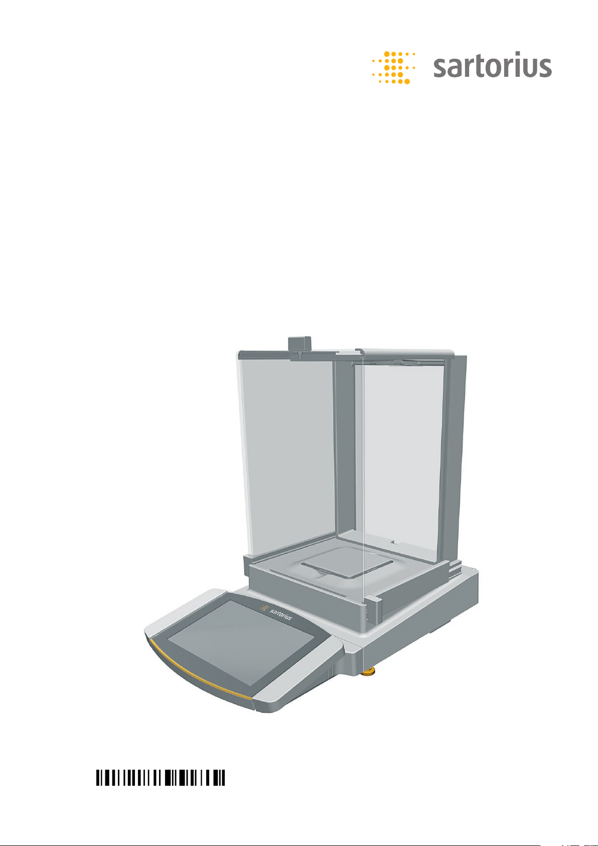
3.1 Device Overview
9
1
2
6
8
7
6
Fig. 1: Semi-microbalance with motorized draft shield with ionizer and electronics module (example)
Pos. Designation Description
1 Weighing chamber
2 Manufacturer’s ID label Not depicted
3 Weighing module
4 Electronics module Only for semi-microbalances with electronics module
5 Leveling foot Motorically adjustable
6 Palm-operated key Opens and closes the side and upper panel of the draft shield
7 Display and control unit
8 Operating display Touchscreen
9 Level
5
3
4
10 Cubis® MCA Operating Instructions
Page 11
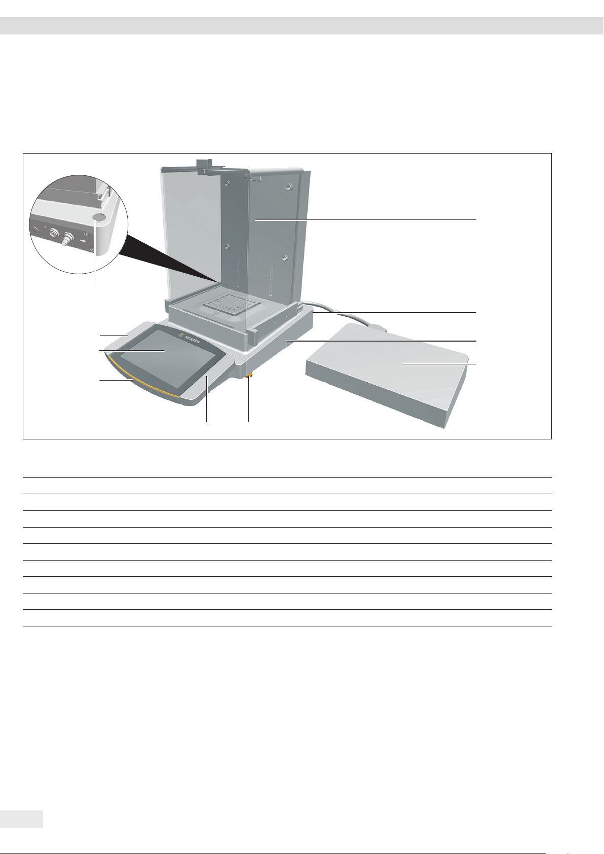
3.2 Draft Shield
Device Description
1
32
4
5
6
7
Fig. 2: Precision balance with frame draft shield, analytical balance with motorized analytical draft shield, and precision balance with manual analytical draft shield
(example)
Pos. Designation Description
1 Frame draft shield Is placed on the shield plate.
2 Analytical draft shield Can be opened at the door handle of the upper panel or at the door handles of the side
panels. Is motorized in some models.
3 Housing back plate Manufactured from metal and plastic parts
4 Upper draft shield panel Used to open the upper panel. Can be opened manually and is motorized in some models.
5 Rear panel Glass
6 Front panel Glass
7 Side panel Can be opened manually and is motorized in some models.
Cubis® MCA Operating Instructions 11
Page 12
Device Description
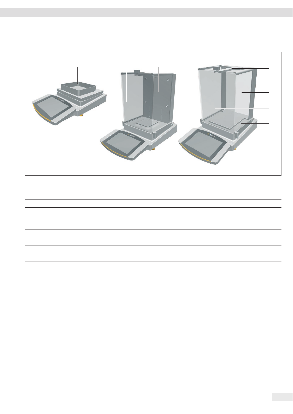
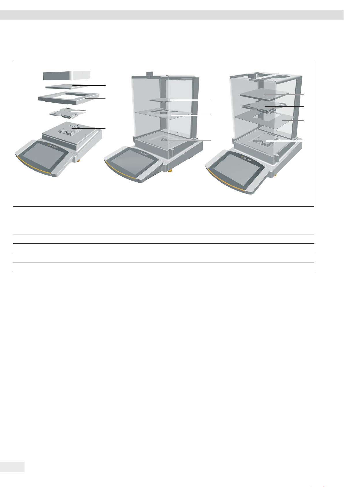
3.3 Weighing Pan and Associated Components
1
3
2
4
1
1
2
3
3
4
Fig. 3: Precision balance with frame draft shield, analytical balance with manual analytical draft shield, and precision balance with manual analytical draft shield
(example)
Pos. Designation Description
1 Weighing pan
2 Pan support Only for models with pan support
3 Shield plate
4 Pan retainer
4
12 Cubis® MCA Operating Instructions
Page 13
Device Description
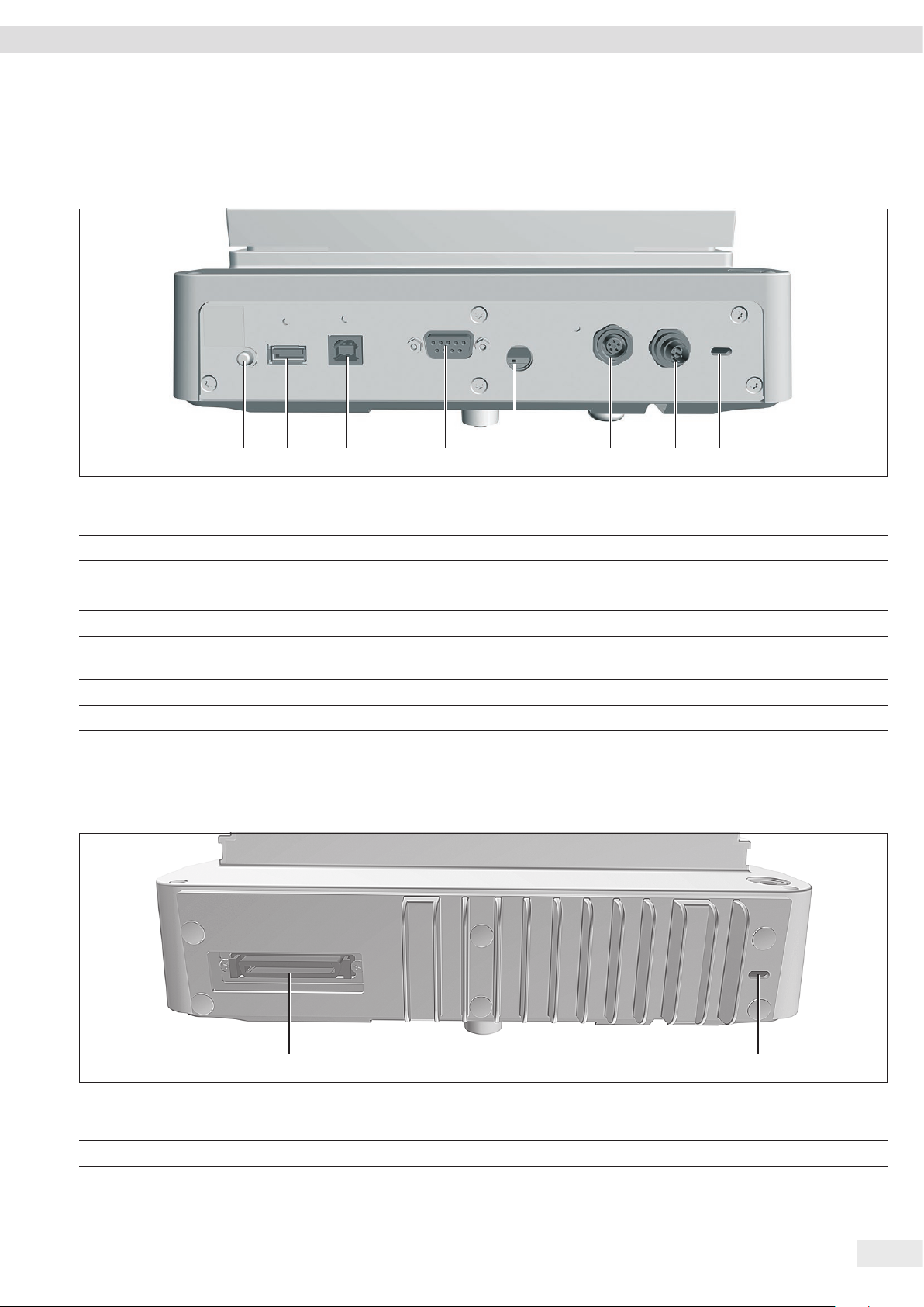
3.4 Connections and Components on the Weighing Module
3.4.1 Analytical Balance and Precision Balance
1 2 3 4 5 6 7 8
Fig. 4: Connections on the weighing module of the analytical balance and precision balance (example)
Pos. Designation Description
1 On key Switches the device on from standby mode.
2 USB-A connection For USB accessories, e.g. printers, USB mass storage devices, barcode scanners
3 USB-B connection For connection to a PC
4 COM-RS232 connection 9-pin, for connection to a PC or PLC
5 Menu access switch Protects the device from changes to the device settings. Is sealed for conformity-
assessed devices.
6 Peripheral connection For connecting Sartorius accessories
7 Power supply For connection to the power supply
8 Slot For attaching a “Kensington” anti-theft device
3.4.2 Semi-microbalance with Electronics Module
1 2
Fig. 5: Connections on the weighing module of the semi-microbalance with electronics module (example)
Pos. Designation Description
1 Electronics module connection For connecting the electronics module to the weighing module
2 Slot For attaching a “Kensington” anti-theft device
Cubis® MCA Operating Instructions 13
Page 14
Device Description
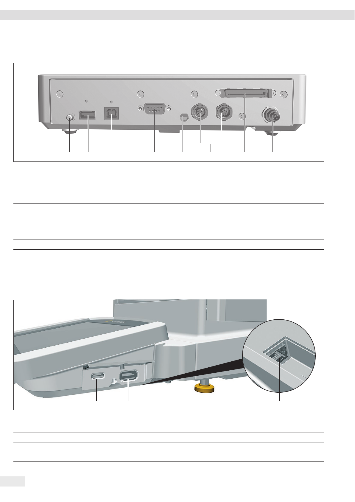
3.5 Connections and Components on the Electronics Module
1 2 3 4 5
Fig. 6: Connections on the electronics module (example)
6
7
8
Pos. Designation Description
1 On key Switches the device on from standby mode.
2 USB-A connection For USB accessories, e.g. printers, USB mass storage devices, barcode scanners
3 USB-B connection For connection to a PC
4 COM-RS232 connection 9-pin, for connection to a PC or PLC
5 Menu access switch Protects the device from changes to the device settings. Is sealed for conformity-
assessed devices.
6 Peripheral connection For connecting Sartorius accessories
7 Weighing module connection For connecting the electronics module to the weighing module
8 Power supply For connection to the power supply
3.6 Connections on the Display and Control Unit
1 2 3
Fig. 7: Connections on the display and control unit (example)
Pos. Designation Description
1 USB-C connection For USB mass storage devices
2 USB-A connection For USB accessories, e.g. printers, USB mass storage devices, barcode scanners
3 Ethernet connection For connecting an Ethernet cable
14 Cubis® MCA Operating Instructions
Page 15
Device Description
3.7 Conformity-assessed Devices
Some settings of conformity-assessed models are protected against user changes,
e.g. “external calibration” for devices in accuracy class II. This measure is intended to
ensure the suitability of the devices for use in legal metrology.
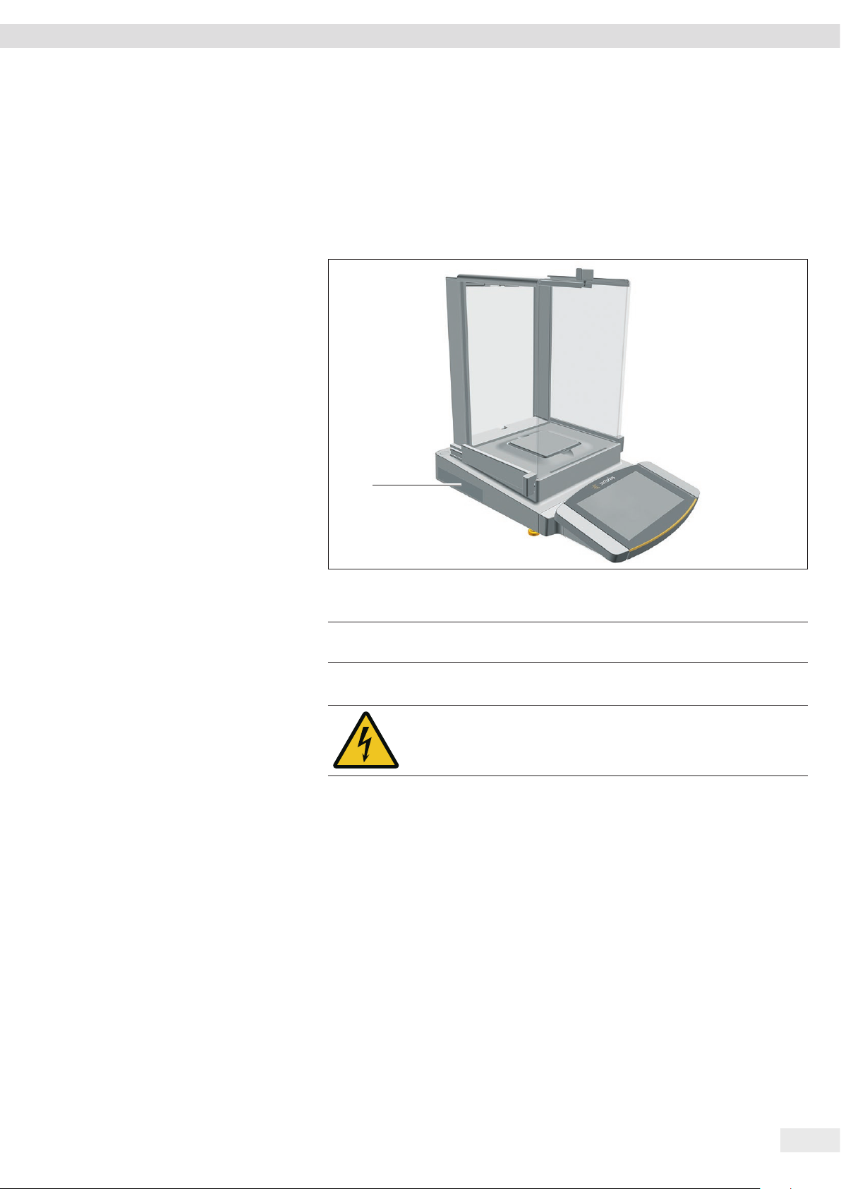
3.8 Symbols on the Device
1
Fig. 8: ID label on the device (example)
Pos. Designation Description
1 Manufacturer’s ID label Displays the metrological data of the device.
Conformity-assessed models only
Symbol Meaning
During operation, parts in the device may be live. Only electricians
may have access to and work on these parts, such as for
maintenance and repairs.
Cubis® MCA Operating Instructions 15
Page 16
Operating Concept
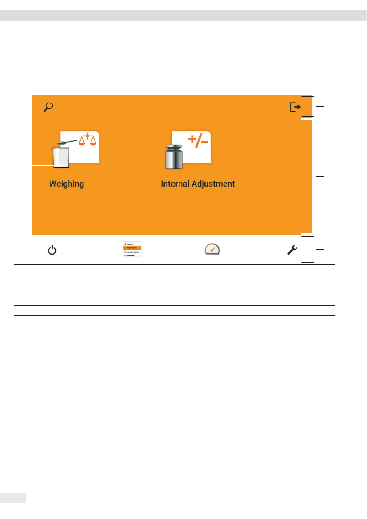
4 Operating Concept
4.1 Operating Elements in the Main Menu
4
1
2
3
Fig. 1: Operating elements in the main menu (example)
Pos. Designation Description
1 Navigation and function bar − Enables navigation, searching, filtering, and sorting in menus and lists.
− In the “Settings” Menu: Displays the name of the menu.
2 Available tasks Displays all tasks available for the active user.
3 Function bar Displays available submenus and operating functions for the current display
and current user.
4 Task Starts the described task.
16 Cubis® MCA Operating Instructions
Page 17
Operating Concept
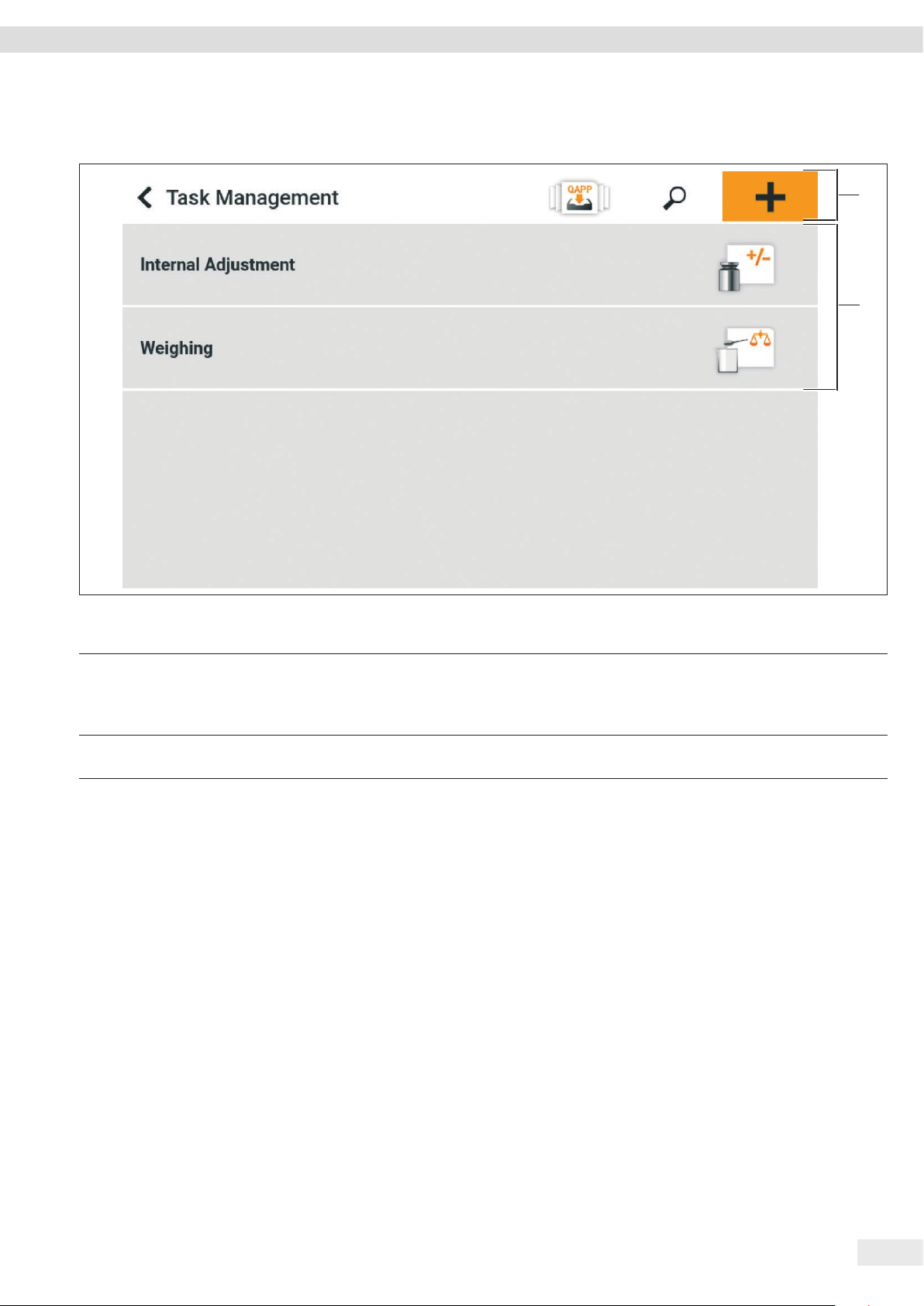
4.2 Operating Elements in the Task Management Menu
1
2
Fig. 2: Operating elements in the Task Management Menu (example)
Pos. Designation Description
1 Navigation and function bar − Enables navigation and searching in menus and lists.
− Enables the addition of tasks.
− Opens the QAPP center.
− Displays the name of the menu.
2 Available tasks − Displays all available tasks.
− Opens a summary of the properties for the displayed task.
Cubis® MCA Operating Instructions 17
Page 18
Operating Concept
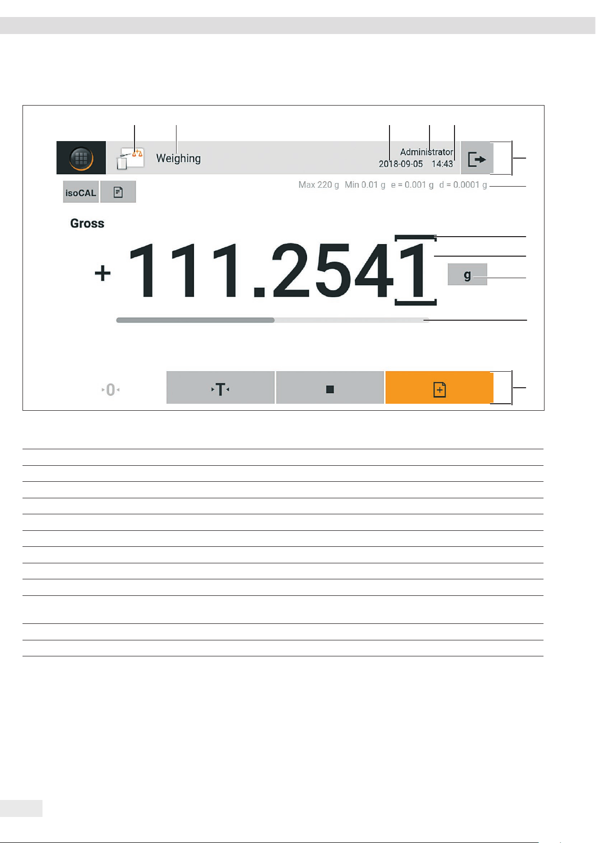
4.3 Operating Elements in the Weighing Display
21 3 4 5
6
7
8
9
10
Fig. 3: Weighing display (example)
Pos. Designation Description
1 Application symbol Displays the symbol for the active application.
2 Task name Displays the name of the active task.
3 Date display Displays the current date.
4 User name Displays the name of the active user profile.
5 Time display Displays the current time.
6 Navigation bar Enables navigation in menus.
7 Metrological data
8 Marked location Marks the differentiated location.
9 Weight value display In the selected unit and resolution.
10 Weighing unit Displays the selected unit, e.g. grams, [g].
Enables the unit and resolution to be selected.
11 Bar graph Displays the measured value as a percentage of weighing capacity utilization.
12 Function bar Displays available operating functions for the current display.
11
12
18 Cubis® MCA Operating Instructions
Page 19
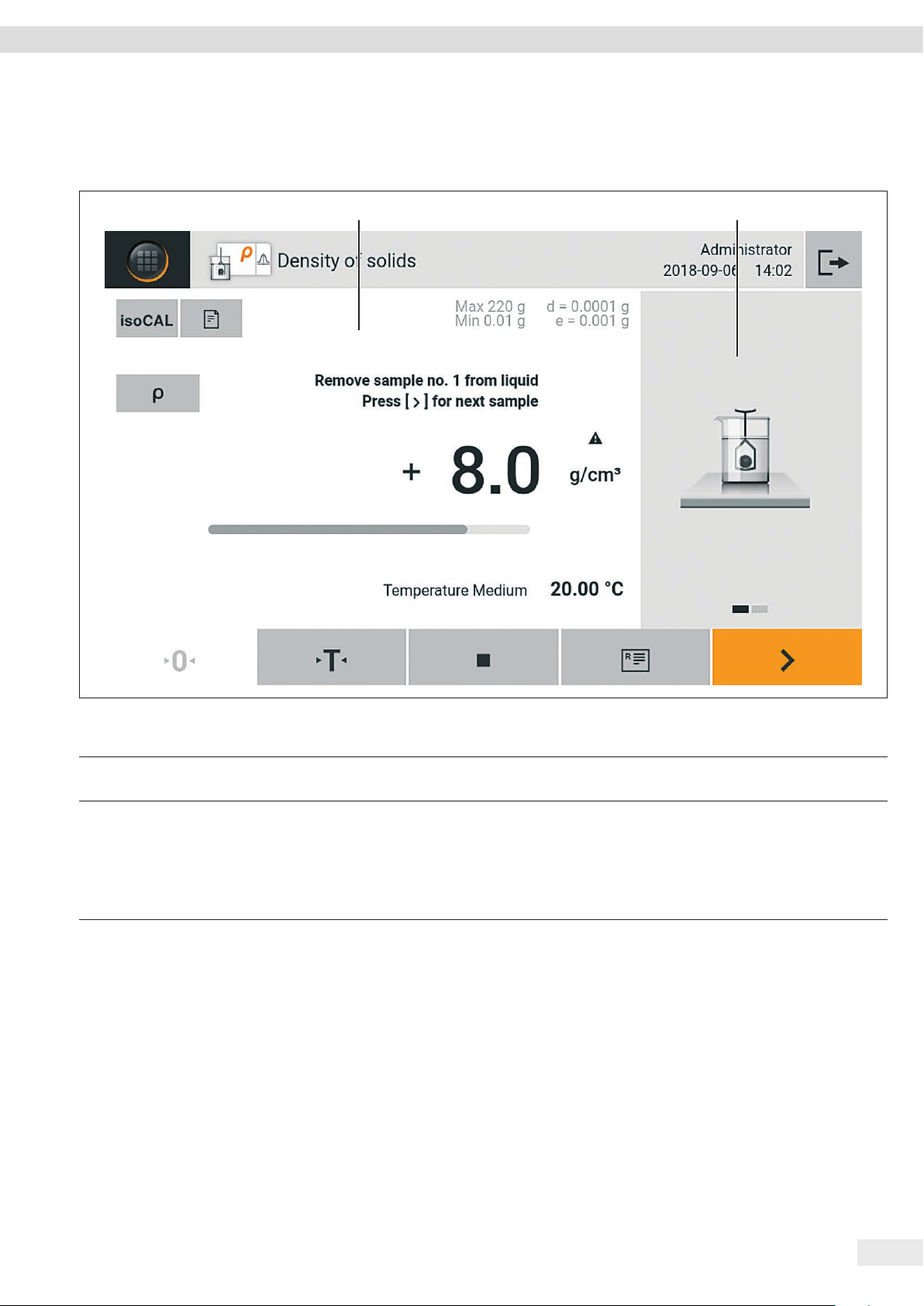
4.4 Advanced Operator Guidance
Advanced applications have advanced operator guidance.
1 2
Operating Concept
Fig. 4: Advanced operator guidance (example)
Pos. Designation Description
1 Weighing display with operator
guidance
2 Advanced operator guidance Guides the user through the active task. Includes 2 or 3 convertible displays
depending on the selected application:
− First display: Shows the step currently being carried out as a graphic display.
− Second display: Shows the current parameters for the task.
− Third display, only for applications with statistics function: Represents statistical
information as a curve.
Cubis® MCA Operating Instructions 19
Page 20
Operating Concept
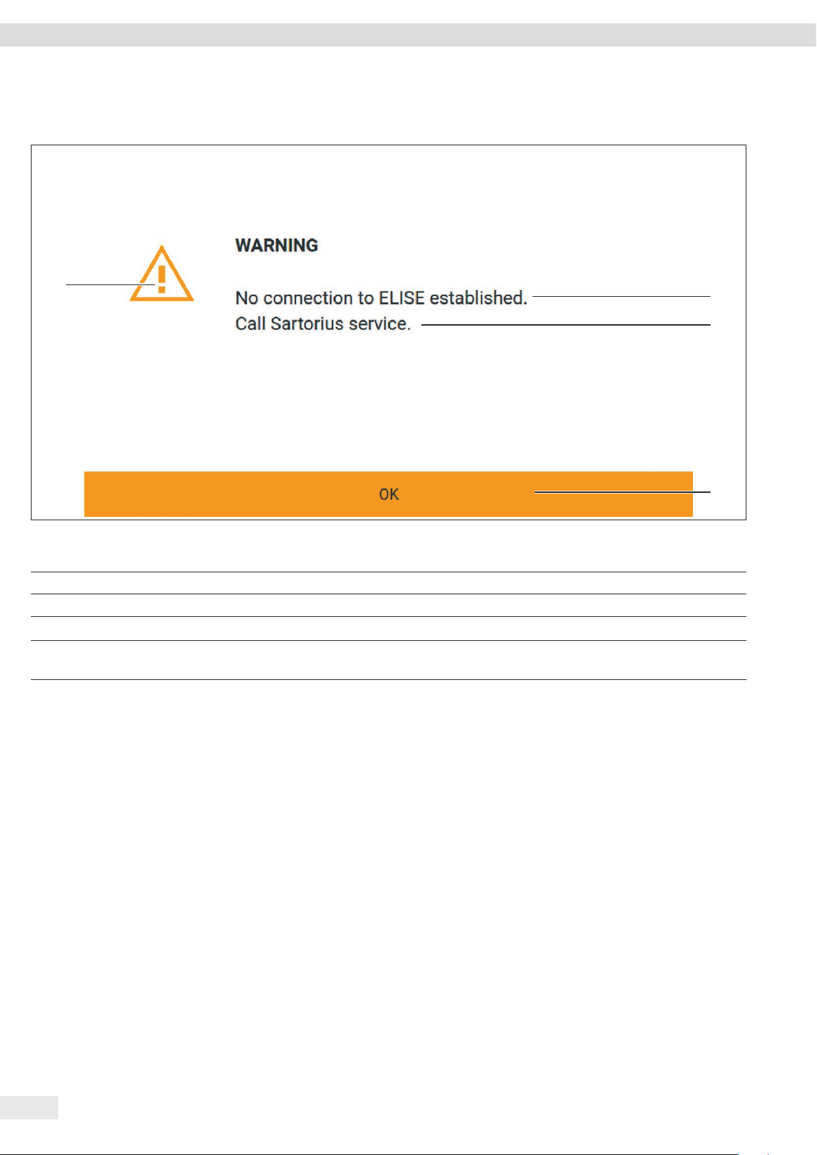
4.5 Messages
4
Fig. 5: Error message (example)
Pos. Designation Description
1 Description Specifies the cause.
2 Remedy Specifies the measures necessary to eliminate the cause of the message.
3 Confirm Confirms and closes the message.
4 Message type Indicates that the message is a status message, warning message, or an
error message.
1
2
3
20 Cubis® MCA Operating Instructions
Page 21
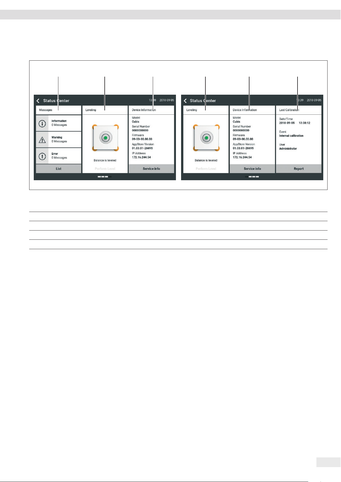
4.6 Self-diagnosis Display
1 2 3 2 3 4
Operating Concept
Fig. 6: Self-diagnosis display (example)
Pos. Designation Description
1 Messages Displays information, warning, and error messages.
2 Leveling status Displays the status of the level.
3 Status for the device Displays the general device information.
4 Calibration and adjustment report Displays the data for the last and next adjustment and calibration.
Cubis® MCA Operating Instructions 21
Page 22
Operating Concept
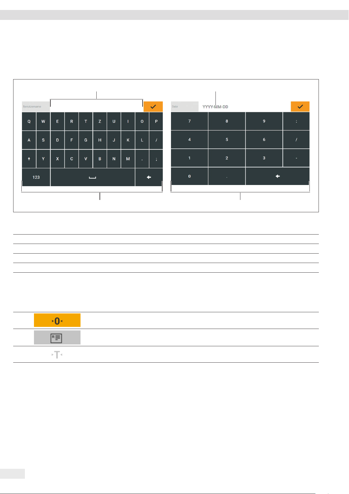
4.7 Keypad
The keypad is used for entering values in entry fields. If an entry field is activated: The alphanumeric keypad or numerical keypad
appears.
1
4 3
Fig. 7: Alphanumeric keypad and numerical keypad (example)
2
Pos. Designation Description
1 Entry field
2 Input assistance Indicates which values must be entered in the input field, e.g. numbers only.
3 Numeric keypad
4 Alphanumeric keypad
4.8 Status Display of the Buttons
Pos. Symbol Designation Description
1
2
3
Predominant button Indicates that the function must be executed.
The button is color-highlighted.
Secondary button Indicates that the function can be executed.
The button is highlighted gray.
Inactive button Indicates that the function currently cannot be
executed. The button is grayed out.
22 Cubis® MCA Operating Instructions
Page 23
Operating Concept
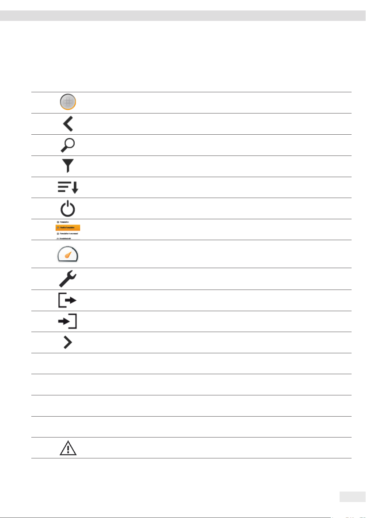
4.9 Buttons in the Operating Display
4.9.1 Buttons for Navigation or Organization in Displays
Pos. Symbol Designation Description
1
[Menu] button Quits the active task and opens the main menu.
2
3
4
5
6
7
8
9
10
[Back] button − Returns to the previous display.
− In the main menu: Accesses the last-performed task.
[Search] button Displays options for browsing tasks and list elements.
[Filter] button Displays options for filtering tasks and list elements.
[Sort] button Displays options for sorting tasks and list elements.
[Standby] button Switches the operating display to standby mode.
[Task Management] button Opens Task Management.
[Status Center] button Opens the Status Center.
[Setup] button Opens the “Settings” menu.
[User Logout] button Logs the currently active user out and accesses the login display.
11
12
13
14
15
16
17
Service info
Device info
List
Leveling
[User Login] button Accesses the login display.
[Next] button Accesses the next display, e.g. the next processing step for a wizard.
[Service Info] button Opens the “Settings / Device Settings / Device Information /
Service” menu.
[Device Info] button Opens the “Settings / Device Settings / Device Information /
General Device Information” menu.
[Status List] button Opens an overview of all current status messages, warning
messages, and error messages.
[Leveling] button Opens the Leveling Wizard.
[Warning] button Opens the list of current warning messages.
Cubis® MCA Operating Instructions 23
Page 24
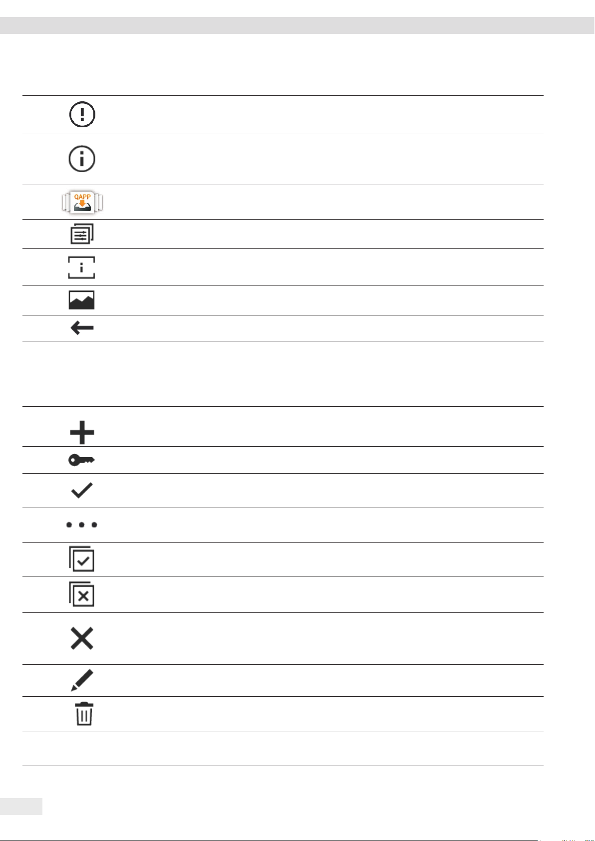
Operating Concept
Pos. Symbol Designation Description
18
[Error] button Opens the list of current error messages.
19
[Info] button − Opens a display with additional information using the current
menu.
− In the self-diagnosis display: Opens the list of current status
messages.
20
21
22
23
24
[QAPP Center] button Opens the QAPP center.
[Profile Management] button Opens Profile Management.
[Details] button Shows additional information about an element.
[Display Image] button Displays available images or videos.
[Close Menu] button Closes the menu.
4.9.2 Buttons for Editing or Managing Entries
Pos. Symbol Designation Description
1
[New] button − In Task Management: Starts the wizard for creating a new task.
− In Profile Management: Starts the wizard for creating a new
weighing or print profile.
2
[Activate QAPP] button Opens the display for activating an application.
3
4
5
6
7
8
9
10
Licensing
[OK] button Saves a selection or entry.
[More] button Shows the keypad for entering a user-defined value.
[Select All] button Selects all elements of a list.
[Deselect All] button Deselects the selection for all elements of a list.
[Cancel] button − Cancels the current process without saving the changed
settings or values.
− In the display for editing the print memory: Marks the selected
value as invalid.
[Edit] button Accesses the Adjustment Wizard for editing the displayed element,
e.g. for setting the parameters for a task.
[Delete] button Deletes the selected element.
[License] button Opens the entry field for the license key for activating a QAPP
package or application.
24 Cubis® MCA Operating Instructions
Page 25
Operating Concept
Pos. Symbol Designation Description
11
[Keypad] button Shows the keypad.
12
[Lock] button Opens the entry field to change the password for the active user.
4.9.3 Weighing and Print Function Buttons
Pos. Symbol Designation Description
1
2
3
4
5
6
7
isoCAL
Prc
Tare 1 0.00 g
[Leveling] button Opens the Leveling Wizard.
[isoCAL] button Starts the isoCAL function.
[Result] button Toggles between the result and weight value display for the current
application, e.g. weighing in percent.
[Zero] button Starts zeroing.
[Tare] button Starts taring.
[Tare 1] button Stores the current weight value in the tare 1 memory.
[Tare 1 Entry] button Opens an entry field for manually entering the tare 1 value.
8
9
10
11
12
13
14
15
16
17
[Delete Tare 1] button Deletes the tare 1 memory.
[Start] button Starts the selected application.
[Quit] button Quits the active application and opens the main menu.
[Confirm] button Confirms the current display and initializes the next step.
[Save] button Saves the weight value and sends it to the print memory.
[Print memory] button Opens the Print Memory display.
[Print] button − If the Print Memory is displayed: Exports the saved print orders
via the integrated data interfaces.
− If the weighing display is displayed and the prompt for the
sample ID is activated: Opens the entry field for the prompt for
the sample ID.
[Ionizer] button Starts an ionization process.
g
[Toggle between weight units]
button
− Toggles between the weight units and the resolution.
− Accesses the “Toggle between weight units” function menu.
[Restart] button If an application is active: Deletes the saved values and restarts the
application.
Cubis® MCA Operating Instructions 25
Page 26
Operating Concept
Pos. Symbol Designation Description
18
[Report] button If an application is active, e.g. density determination: Displays a
report about the progress of the application.
19
[Result report] button If an application is active, e.g. density determination: Displays a
report about the result of the application.
4.10 Displays in the Operating Display
Pos. Symbol Designation Description
1
2
3
4
5
6
g
Gross
[Leveling] display Indicates that the device is not leveled.
[Print memory] display Indicates that the elements are located in the print memory.
[Unit symbol] display Indicates the set weight unit, e.g. [g] for “grams”.
[Result] display Indicates whether the weight value being displayed is a gross value
or the result of an application.
[Invalid weight value] display − Indicates that the display does not contain a weight value, but
is instead the calculated result of an application, e.g. for the
“Totalizing” application.
− For conformity-assessed devices: Indicates a fault. The cause of
this fault is displayed in the self-diagnosis display.
[Sign] display Indicates whether the value being displayed is positive or negative.
7
8
9
10
11
12
[Current page] display − Indicates that the current display is a multi-page display.
− Indicates which page of a multi-page display is being displayed
currently.
[Copy] button Indicates that data are being copied.
[Selection] display Indicates that an entry is selected in a list.
[Target value] display Displays the target value in the bar graph display.
[Factory mode] display Indicates that the device is being operated in the factory default
mode.
[Service mode] display Indicates that the device is being operated in the service mode.
26 Cubis® MCA Operating Instructions
Page 27

Operating Concept
4.11 User Management
4.11.1 User Profiles
In the factory, 4 user profiles are created for the device. One role is assigned to each
user profile. Each role has rights to operate the device. The rights assigned to each
role depend on which device functions the user has to use.
User profiles can be adapted.
4.11.2 User Login
The user must log in to the login display with a user profile. Various setting options
and tasks are displayed in the operating display depending on the user profile and
role.
4.12 Profile Management
Weighing and print profiles can be created. These profiles can be assigned to a task.
4.13 Applications and Tasks
Device functions such as weighing or calibration and adjustment are carried out
using tasks. Applications must be assigned to a task.
A task is visible to all users who are approved for this task.
The device is supplied with some freely accessible applications that can be used to
carry out the most important functions.
Additional applications may be activated for a fee.
Cubis® MCA Operating Instructions 27
Page 28

Operating Concept
4.14 Menu Structure
4.14.1 Main Menu
t Navigating in menus (see Chapter 4.15, page 32).
Level 1 Level 2 Level 3 Description
Task management (task menu)
QAPP center Display the available QAPP packages.
Status center Display information on the device status, e.g.
Settings General device informa-
tion
User Management
Profile Management
Device Settings
Connections
Device Maintenance
Displays all available tasks.
Opens a summary of the properties for the
displayed task.
level status.
4.14.2 “Settings” Menu
Depending on the approved applications, the device may display additional menus.
t Navigating in menus (see Chapter 4.15, page 32).
Level 1 Level 2 Level 3 Description
Device
information
General device
information
Service Service contact Display the responsible contact at Sartorius
Manufacturer Display information about the device’s
manufacturer.
Model Display the device’s model ID.
Serial number Display the device’s serial number.
Version of device firmware
with check number
QAPP center version Display the version of the QAPP center.
IP address Display the IP address of the device.
MAC address Display the MAC address of the device.
Telephone number Display the telephone number for Sartorius
E-mail address Display the e-mail address for Sartorius Service.
Technical hotline Display the technical hotline for Sartorius Service.
Maintenance contact Display the responsible contact for maintenance
Next scheduled maintenance Display the date for the next scheduled
Maintenance cycle Display the maintenance cycle.
Website Display the website for Sartorius Service.
Display the version of the device firmware with
check number.
Service.
Service.
measures.
maintenance.
28 Cubis® MCA Operating Instructions
Page 29

Operating Concept
Level 1 Level 2 Level 3 Description
Alibi memory Display, filter, or browse the contents of the Alibi
memory.
Weigh range Ranges 1–4 Display the values for maximum load, minimum
load, scale interval, and calibration step interval
for weigh ranges 1–4.
Diagnostics information Version of device firmware
with check number
Display the version of the device firmware with
check number.
QAPP center version Display the version of the QAPP center.
Restore mode version Display the restore mode version.
BAC balance processor version Display the version of the BAC processor.
APC application processor
Display the version of the APC processor.
version
MCU control processor version Display the version of the MCU processor.
WPC draft shield processor
Display the version of the WPC processor.
version
Software licenses The list of all open source software modules used.
User
Management
Profile
Management
4 standard user profiles Summary of the properties
of the active user profile
Weighing List of available weighing
profiles
Report on USB Printer
List of available print profiles Display or edit all print profiles available for the
YDP30
Display or edit the active user profile.
Display or edit all weighing profiles available for
the active user.
active user.
Device Settings Date and time Date format Define the date display format.
New date Enter a date.
Time format Define the time display format.
New time Enter a new time.
NTP, Network Time Server Activate or deactivate time synchronization via
NTP.
IP address of the NTP server Enter the NTP server IP address.
Time zone Determine the time zone.
Leveling Automatic leveling (before
calibration / adjustment
Activate or deactivate automatic leveling before
each calibration / adjustment process.
function)
Leveling alert levels Set the alert level for the message indicating that
the device has not been leveled.
isoCAL isoCAL function Set the isoCAL function.
isoCAL alert levels Set the alert level for the message indicating that
the isoCAL function must be executed.
Device identifier ID1 – 2 Determine the device identifier.
Draft shield Left / right key Set the function of the left and right palm-
operated keys.
Only for devices with a motorized draft shield
Ionizer Ionizer function Define the switch-on behavior for the ionizer.
Only for devices with an ionizer
Ionizer intensity Define the intensity of the ionization process.
Cubis® MCA Operating Instructions 29
Page 30

Operating Concept
Level 1 Level 2 Level 3 Description
Operating duration Define the duration of the ionization process in
seconds.
Self-diagnosis Software integrity Display the software status, e.g. the available
memory.
Internal sensors Settings for monitoring the device components,
e.g. the clock module battery.
Internal actuators Configure settings for device components, e.g.
the motor current for the calibration weight.
Environment Configure settings for monitoring the
environment, e.g. environmental movements.
Switch-on behavior Zero/tare at switch-on Activate or deactivate automatic zeroing and
taring when starting the device.
Automatic login, last user Activate or deactivate automatic log-in of the
last user when starting the device.
Automatic start, last task Activate or deactivate automatic start of the last
task when starting the device.
Properties display Display brightness Define the brightness of the operating display.
Switching the system on / off Activate or deactivate the “energy saving”
function.
Color scheme Displays the color scheme of the operating
display.
Sound (loudspeaker) Sound for touch and keypad
operation
Sound for the end of execution
of an action
Activate or deactivate the acoustic signal when
operating a button.
Activate or deactivate the acoustic signal for the
end of an action.
Sound for messages Activate or deactivate the acoustic signal for
messages.
Connections Website for the balance Website Determines the settings for the display of the
website for the device.
Remote control display Define the settings for controlling the device
remotely.
Interfaces Serial transmission via Ethernet Display the profile for the Ethernet connection.
Edit, create or delete the profile.
USB-B connection Display the profile for the USB-B connection.
Edit, create or delete the profile.
RS232 connection Display the profile for the RS232 connection.
Edit, create or delete the profile.
SBI protocol Format Configure the settings for the data output and
data output format.
Output Define whether the output takes place with or
without stability.
Automatic data output Activate or deactivate the output rate for
automatic data output.
30 Cubis® MCA Operating Instructions
Page 31

Operating Concept
Level 1 Level 2 Level 3 Description
PC direct protocol Output Define the output format for the data exchange
between the balance and the PC.
Decimal marker of readout Define the decimal separator character.
Connected devices Motion sensor Define the number and function of the gestures
and sensitivity of the motion sensor.
Only available if a motion sensor is connected to
the device.
External USB switch For keys 1–3 on the USB switch, determine which
functions are executed when the keys are pressed
and released.
Only available if an external USB switch is
connected to the device.
Device
maintenance
Update firmware Update the firmware. The menu is not available
for conformity-assessed devices.
Update QAPP center Update the QAPP center.
Export options Determine the settings for exporting data from
the device.
Import options Determine the settings for importing data to the
device.
Restore factory default
Reset the device to factory settings.
settings
Cubis® MCA Operating Instructions 31
Page 32

Operating Concept
4.15 Navigating the Menus
Procedure
t To open a menu from the main menu: Tap on the desired menu button in the
function bar.
y The menu opens and the name of the open menu is displayed in the navigation
bar.
t To return to the main menu from other displays: Press the [Menu] button or press
the [Back] button (multiple times) until the main menu is displayed.
t To exit a display: Press the [Back] or [Cancel] button.
t To scroll through the tasks available in the main menu: Swipe the task list to the
left or right.
t To scroll through the list of options in an administration menu (settings, tasks,
applications, etc.): Swipe the list downwards or upwards.
t To display the next page in a display containing several pages, e.g. in the self-
diagnosis display: Swipe the display to the left.
t To display the previous page in a display with several pages: Swipe the display to
the right.
t If a value needs to be selected from a list:
t Scroll to the desired value in the display. In order to do so, swipe the display
upwards or downwards.
t Press the desired value.
t To confirm the selection: Press the [OK] button.
y The selected value is saved and the list closes.
32 Cubis® MCA Operating Instructions
Page 33

Operating Concept
t If elements from a display need to be filtered or a display needs to be browsed:
t Press the [Search] or [Filter] button.
y The keypad is displayed.
1
t Type the searched value or value to be filtered into the entry field (1) using
the keypad.
t Press the [OK] button.
t To close the entry field for searching and filtering without starting a search or
filter operation: Enter no value in the entry field or delete the entered value.
t Press the [OK] button.
t If language-specific characters need to be entered using the keypad:
t Press and hold a letter on the keypad.
y If language-specific characters are available for the letter being pressed:
A display opens containing all the language-specific characters available for
the letter being pressed.
t To select a language-specific character and return to the keypad display:
Tap on the desired language-specific character.
Cubis® MCA Operating Instructions 33
Page 34

Installation
5 Installation
5.1 Scope of Delivery
Item Quantity
Device 1
Weighing pan 1
Shield plate 1
For models with pan support: Pan support 1
AC adapter 1
For models with a motorized draft shield: Palm-operated key 2
Country-specific power supply cable with test seal 1
USB connection cable 1
In-use dust cover for display and control unit 1
For models with analytical draft shield: Dust cover 1
For models without a draft shield: In-use dust cover for the weighing
module
For semi-microbalances: Electronics module with power supply cable 1
For semi-microbalances: Connection cable for electronics module 1
1
5.2 Selecting an Installation Site
Procedure
t Make sure that the following conditions are met at the installation site:
Condition Features
Ambient conditions Suitability tested (see Chapter “15.6 Ambient
Conditions”, page 78)
Setup surface Stable, even surface that is not exposed to
vibrations
Not directly against a wall
Sufficiently dimensioned for the device and the
peripheral devices (device space requirements see
Chapter “15.1 Dimensions and Weight”, page 76;
peripheral device space requirements see instructions for the peripheral devices, e.g. printer)
Sufficient load-bearing capacity for the device
and the peripheral devices even when full (device
weight see Chapter “15.1 Dimensions and Weight”,
page 76; weight of the peripheral devices see
instructions for the peripheral devices, e.g. printer)
Access Barrier-free
34 Cubis® MCA Operating Instructions
Page 35

Installation
5.3 Unpacking the Device
Procedure
t Lift the device with the styrofoam padding out of the packaging.
t Place the device in the styrofoam padding on its side.
t Lift the styrofoam padding off the device.
t NOTICE Glass breakage due to incorrect handling of the device! Only lift the
device by its base.
t Place the device on its base.
t Keep all parts of the original packaging, e.g. to return the device.
5.4 Removing the Display and Control Unit
5.4.1 Positioning the Display and Control Unit
The display and control unit can be removed. This enables the flexible setup of the
display and control unit at the workplace.
Tool: 1 Torx Allen key, T20
Material: 1 soft support base
Requirements
− The weighing pan and the associated components have not been set up.
− For a device with an analytical draft shield or flat glass draft shield: The side
panels and upper panel have not been fitted.
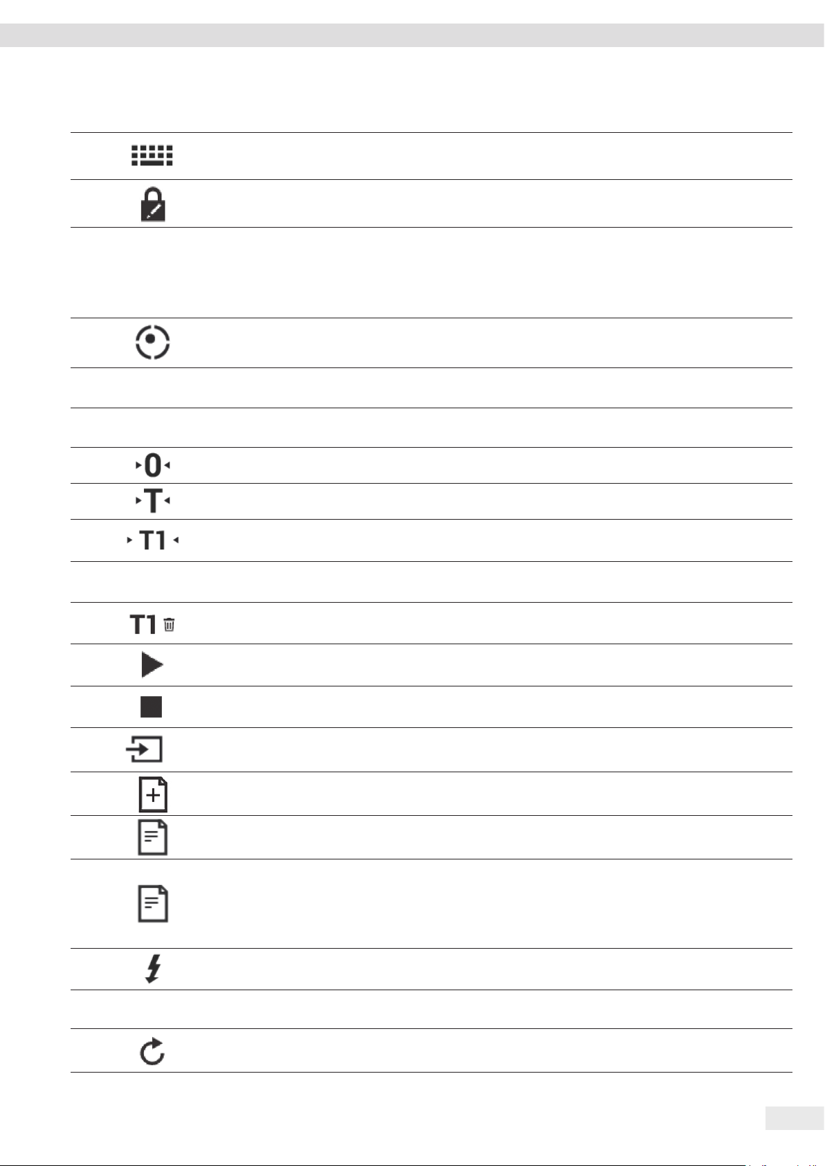
Procedure
t Turn the device on its side and place it on the soft support base.
t To loosen the control unit’s retainer: Use the Torx Allen key to remove both
screws.
t Remove the control unit and re-insert both screws into the threaded holes.
Cubis® MCA Operating Instructions 35
Page 36

Installation
1
t Pull the connection cable between the control unit and the weighing module (1)
out of the control unit’s retainer to the required length.
t Place the device back on the device base on a level surface.
5.5 Connecting the Ethernet Cable
Material: 1 Ethernet cable
1 soft support base
Requirements
− The weighing pan and the associated components have not been set up.
− For a device with an analytical draft shield or flat glass draft shield: The side
panels and upper panel have not been fitted.
Procedure
t If the display and control unit is attached to the weighing module or electronics
module: Turn over the device and place on a soft surface.
t If the display and control unit is removed from the weighing module or
electronics module: Turn over the display and control unit and place on a soft
surface.
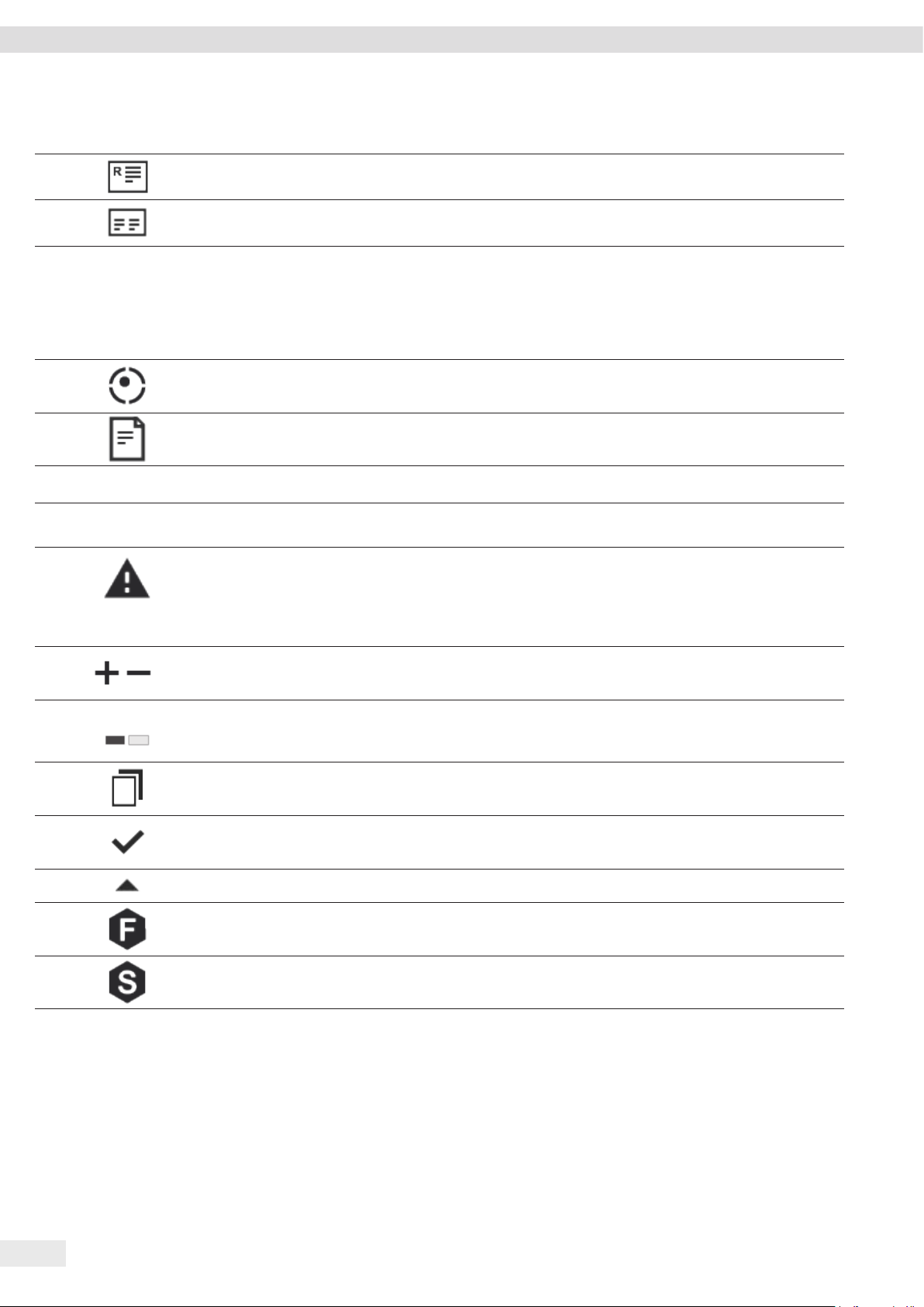
t Remove the cover (3) of the Ethernet connection socket on the underside of the
display and control unit.
t Plug the Ethernet cable into the Ethernet connection socket.
t If the display and control unit is attached to the weighing module or electronics
module: Place the Ethernet cable into the cable channel (1) and turn the cable
lock (2) using the Ethernet cable.
t If the display and control unit is removed from the weighing module or
2 13
electronics module: Place the Ethernet cable in the cable channel.
t Place the device back on the device base on a level surface.
5.6 Preparing Below-balance Weighing
The device can be configured for below-balance weighing. Samples can be
suspended for weighing using below-balance weighing, e.g. samples, which do
not fit on the weighing pan.
For below-balance weighing, the hook must be installed in the device base and
the device set up on a weighing table with recess.
36 Cubis® MCA Operating Instructions
In legal metrology:
− The below-balance weighing equipment may not be used.
− The cover of the below-balance weighing equipment may not be opened.
Material: 1 soft support base
1 draft protection shield
1 weighing table with recess
Page 37

Installation
Requirements
− The weighing pan and the associated components have not been set up.
− For a device with an analytical draft shield or flat glass draft shield: The side
panels and upper panel have not been fitted.
Procedure
t Turn the device on its side and place it on the soft support base.
1
underside of the base of the device.
t Pull the cover of the below-balance weighing equipment (1) out.
1
t NOTICE Damage to the device from cross-threading! Ensure that the hook for
below-balance weighing is inserted straight into the thread (1).
t Remove the hook for below-balance weighing (1) from the retainer on the
1
t Set up the device on the weighing table with recess. The hook for below-balance
weighing may not touch the floor.
t Install the draft protection shield.
Cubis® MCA Operating Instructions 37
Page 38

Installation
2
5.7 Installing a Device with an Analytical Draft Shield or Flat Glass Draft Shield
5.7.1 Positioning the Weighing Pan and Associated Components
Procedure
t If this relates to a device with a pan support:
t Place the shield plate (1) on the base of the weighing chamber (2).
1
t Hook the pin on the pan support into the clip on the pan retainer.
t Push the pan support down onto the pan retainer until the pan support lies
parallel to the device housing.
t Place the weighing pan (1) onto the pan support (2).
1
2
38 Cubis® MCA Operating Instructions
Page 39

Installation
t If this relates to a device without a pan support:
t Place the shield plate (2) into the weighing chamber.
t Place the weighing pan (1) into the recess in the shield plate.
1
2
5.7.2 Installing the Analytical Draft Shield
Procedure
t Slide the upper panel into the guide rail (1).
t Gently push the upper panel down. This enables the upper panel to slide
1
completely.
t Slide the upper panel completely into the guide rail.
t Insert the side panels completely into the guide rails.
5.7.3 Installing the Flat Glass Draft Shield
Procedure
1
t Gently tilt the upper panel down. This enables the upper panel to slide completely
into the slot (1).
t Slide the upper panel completely into the slot.
Cubis® MCA Operating Instructions 39
Page 40

Installation
t Insert the side panel completely into the guide rails on the weighing module (2)
1
2
and into the upper guide rails (1).
5.8 Installing a Device with a Frame Draft Shield
5.8.1 Positioning the Weighing Pan and Associated Components
1
2
3
Procedure
t Insert the pin on the pan support into the clip on the pan retainer.
t Push the pan support down onto the pan retainer until the pan support lies
parallel to the device housing.
t Place the shield plate (3) on the device housing.
t Place the weighing pan (2) on the pan support.
t Place the frame draft shield (1) on the shield plate (3).
40 Cubis® MCA Operating Instructions
Page 41

Installation
5.9 Connecting the Electronics Module (Only for Semi-microbalance)
Procedure
t Connect the connection cable to the electronics module’s weighing module
connection.
t Connect the other end of the connection cable to the weighing module’s
electronics module connection.
t To lock the connection cable: Lock the plugs of the connection cable onto both
connections with two clicks in each case.
t NOTICE Damage to the device due to incorrect connection!
t Check the correct fit of the plug contacts.
t There should be no tension on the connection cable, e.g. do not install
directly against a wall.
5.10 Installing Palm-operable Keys (Only for Devices with Motorized Draft Shield)
For models with a motorized draft shield, 2 palm-operable keys can be installed.
Procedure
t Affix both palm-operable keys (1) onto the side of the display and control unit.
1
5.11 Setting Up the Cable Entry (Only for Devices with a Manual Analytical Draft Shield)
For models with a manual analytical draft shield, a cable can be fed into the
weighing chamber, e.g. when using a temperature sensor.
Procedure
t Lift the locking tab (1) on the rear panel of the device.
t Lift the panel (2) out of the device.
2 1
Cubis® MCA Operating Instructions 41
Page 42
Installation
1
1
t Rotate the panel 180° so that the recess (1) in the panel points towards the
weighing module.
t Feed the connection cable into the weighing chamber.
t Insert the panel into the guide groove (1).
t Lift the locking tab (1) on the rear panel of the device and push down the panel.
t Press the locking tab down and close it.
1
5.12 Acclimatization
When a cold device is brought into a warmer area: The temperature difference can
lead to condensation of humidity in the device (moisture formation). Moisture in
the device can lead to malfunctions.
t Allow the device to acclimatize for approx. 2 hours at the installation site.
Ensure that the device is disconnected from the power supply during that time.
42 Cubis® MCA Operating Instructions
Page 43
Getting Started
6 Getting Started
Procedure
t NOTICE Improper connection may damage the device! If the device is connected
using electronic components, e.g. printer, PC: The device must be disconnected
from the power supply. Ensure that the device is disconnected from the power
supply.
t Connect the device using electronic components (see electronic components
instructions).
6.1 Installing the AC Adapter
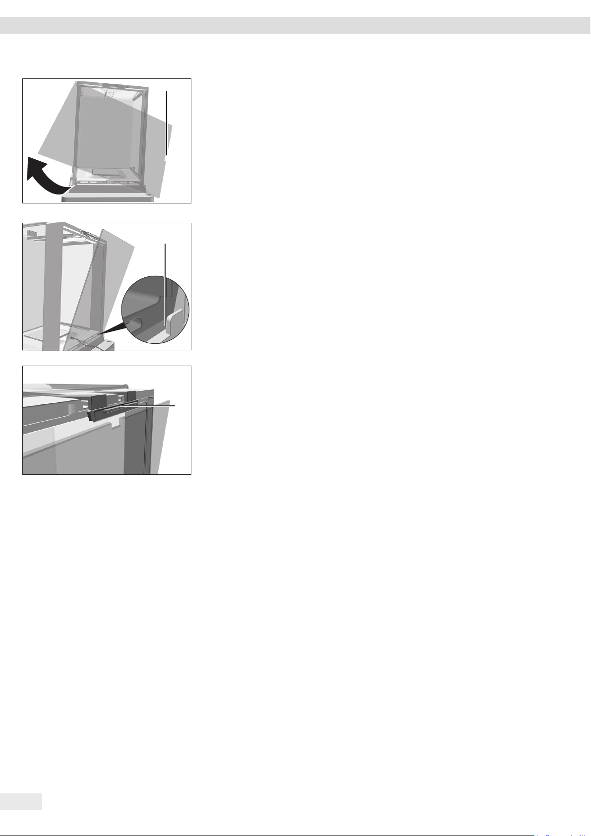
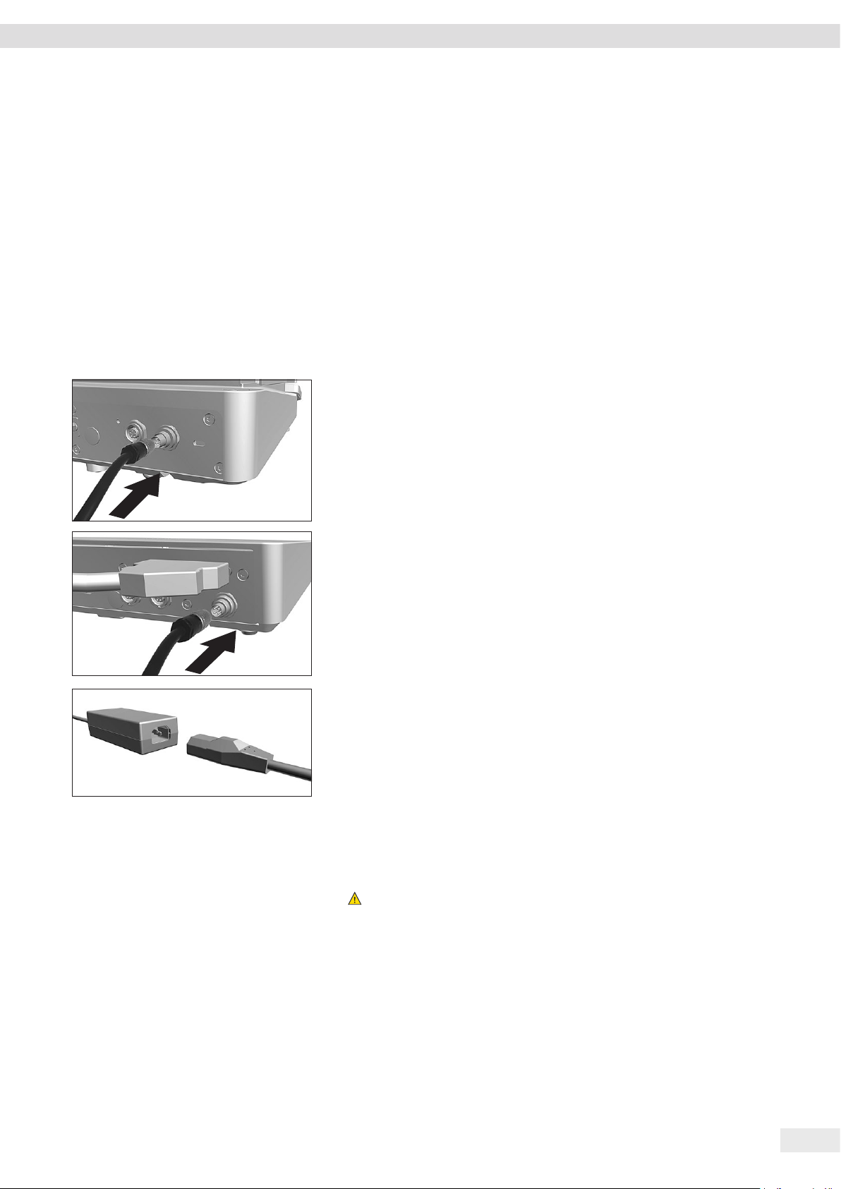
Procedure
t If this relates to a device without an electronics module: Plug the DC supply
cable of the AC adapter into the device’s “power supply” connection socket and
tighten the threaded fitting.
t If this relates to a device with an electronics module: Plug the DC supply cable of
the AC adapter into the electronics module’s “power supply” connection socket
and tighten the threaded fitting.
t Connect the power supply cable to the AC adapter connection.
6.2 Connecting the Power Supply
Procedure
t
WARNING Severe injuries caused by using a defective power supply cable!
Check the power supply cable for damage, e.g., cracks in the insulation.
t If required: Contact Sartorius Service.
t Check whether the country-specific power plug matches the power connections
at the installation site.
t If required: Contact Sartorius Service.
t NOTICE Damage to the device due to excessive input voltage! Check whether the
voltage specifications on the AC adapter match those of the power supply at the
installation site.
t If the input voltage is too high: Do not connect the device to the power
supply.
t Contact Sartorius Service.
Cubis® MCA Operating Instructions 43
Page 44

Getting Started
t Connect the mains plug of the power supply cable to the wall outlet at the
installation site.
y The [Booting device...] display appears in the operating display.
y The [Starting system...] display appears in the operating display.
y The [Starting application...] display appears in the operating display.
y The [Loading] display appears in the operating display.
y The device performs an initial tare function.
44 Cubis® MCA Operating Instructions
Page 45

System Settings
7 System Settings
7.1 Performing System Settings
Default settings can be adjusted for the device and the applications in order to align
with the ambient conditions and individual operating requirements.
The following settings are necessary to operate the device together with connected
components:
− Set up the communication of the connected devices
− Set up additional components
The following settings are recommended to set up the device:
− Set the menu language
− Select date / time format
− Set date / time
− Assign a Password
− Set the behavior of the isoCAL function
− Set the behavior of the motorized draft shield (only for devices with a motorized
draft shield)
Procedure
t Open the main menu.
t Press the [System Settings] button.
t To adjust settings: Open the desired submenu.
t Select the desired configuration value (configuration values, see Chapter “7.4
Parameter List”, page 46).
t Exit the menu.
7.2 Switching Off the isoCAL Function
If the isoCAL function is switched off for a conformity-assessed device, the device
can only be used for legal-for-trade applications in restricted temperature ranges
(see Chapter “15.6.2 Ambient Temperature for the isoCAL Function”, page 79).
The isoCAL function cannot be switched off for all model versions.
Procedure
t In the “Settings / Device Settings / isoCAL” menu, for the “isoCAL function”
parameter, select the “off” configuration value.
7.3 Assign a Password
Procedure
t Log into the device using the user profile; a password should be assigned.
t Open the “Settings / User Configuration” Menu.
t Press the [Lock] button.
y The user password input field is displayed.
t Enter the desired password in the entry field and confirm with the [OK] button.
Cubis® MCA Operating Instructions 45
Page 46

System Settings
7.4 Parameter List
7.4.1 Parameters in the “User Configuration” Menu
Parameters Configuration values Explanation
Name User input Assign a name for the user profile.
Description User input Enter a description for the user profile.
User color Define a user color for the user profile.
Language Set the menu language for the user profile.
Log-on method Determine whether the user password is saved locally on the device or
provided by an IDAP network server.
* Factory setting
7.4.2 Parameters in the “Profile Management” Menu
Parameters in the “Weighing” Submenu
Parameters Configuration values Explanation
Ambient conditions Very stable Sets the ambient conditions to “very stable”: Activates a fast change in the
weight values in the event of a load change with a high output rate.
Recommended for the following work environment:
− Very stable table near the wall
− Closed and calm room
Stable Sets the ambient conditions to “stable”.
Recommended for the following work environment:
− Stable table
− Slight movement in the room
− Slight draft
Unstable* Sets the ambient conditions to “unstable”: Activates the delayed change in
weight values with a reduced output rate.
Recommended for the following work environment:
− Simple office desk
− Room with moving machinery or personnel
− Slight air movement
Very unstable Sets the ambient conditions to “very unstable”: Activates a significantly
delayed change in the weight values and long wait for stability with a
further reduction in the output rate.
Recommended for the following work environment:
− Noticeable and slow floor vibrations
− Noticeable building vibrations
− Weighed goods moved
− Very strong air movements
* Factory setting
46 Cubis® MCA Operating Instructions
Page 47

System Settings
Parameters Configuration values Explanation
Application filter Weighing (final readout)* Activates a filter that enables a fast change in the display for very fast load
changes.
Display changes with minimal load changes (in the digit range) occur more
slowly.
Dosing (initial weighing) Activates a filter that enables a very fast change in the display with
minimal load changes (e.g. when filling containers).
Sensor mode (low filtering) Activates a weak but fast filter that always behaves in the same way for
load changes (e.g. when filling automated systems).
Dynamic mode (without
Deactivates the active application filter.
filtering)
Stability Very high degree of
Sets the stability to “very high degree of accuracy”.
accuracy
High degree of accuracy Sets the stability to “high degree of accuracy”.
Average degree of accuracy* Sets the stability to “average degree of accuracy”.
Fast Sets the stability to “fast”.
Very fast Sets the stability to “very fast”.
Very slow Sets the stability to “very slow”.
Stability delay Very short Sets the stability delay to “very short”: The stability symbol is displayed
after the stability criterion is reached.
Short* Sets the stability delay to “short”: The stability symbol only appears after
a short delay in order to provide a reliable result despite fluctuations.
Medium Sets the stability delay to “medium”: The stability symbol only appears
after a longer delay in order to provide a reliable result in case of higher
fluctuations.
Long Sets the stability delay to “long”: The stability symbol only appears after
a long delay in order to balance out major instability.
Zeroing/taring Without stability Without stability: The function of the [Zero] or [Tare] key is executed
immediately once the key is pressed.
With stability* With stability: The function of the [Zero] or [Tare] key is only executed
after stability is achieved.
At stability At stability: The function of the [Zero] or [Tare] key is executed if stability
exists when the key is pressed.
Automatic zeroing On* Activates automatic zeroing. The display is automatically set to zero in case
of a deviation of 0 less than (X).
Off Deactivates automatic zeroing. Zeroing must be triggered with the [Zero]
key.
Tare preset 1 On* Activates the initial taring / zeroing. The device is tared or zeroed after it is
switched on.
Off Deactivates the initial taring / zeroing: After it is switched on, the device
shows the value before it was last switched off.
* Factory setting
Cubis® MCA Operating Instructions 47
Page 48

System Settings
Parameters Configuration values Explanation
Available units The availability of units may depend on national legislation and is
therefore country-specific. Multiple selection is possible.
mg – milligrams* The device displays the weight in milligrams.
g – grams* The device displays the weight in grams.
kg – kilograms* The device displays the weight in kilograms.
ct – carats* The device displays the weight in carats.
lb – pounds The device displays the weight in pounds.
oz – ounces The device displays the weight in ounces.
ozt – troy ounces The device displays the weight in troy ounces.
tlh – Hong Kong taels The device displays the weight in taels (Hong Kong).
tls = Singapore taels The device displays the weight in taels (Singapore).
tlt – Taiwanese taels The device displays the weight in taels (Taiwan).
tlc = Chinese taels The device displays the weight in taels (China).
GN – grain The device displays the weight in grains.
dwt = pennyweight The device displays the weight in pennyweights.
mom – mommes The device displays the weight in mommes.
tol – tolas The device displays the weight in tolas.
bat – baht The device displays the weight in baht.
MS – mesghals The device displays the weight in mesghals.
N – newtons The device displays the weight in newtons.
Available resolutions Show all decimal places* “Show all decimal places”: All decimal places are shown in the display.
Not available on conformity-assessed devices.
Last decimal place after
load change
Last decimal place of the
1st division
“Reduced by 1 decimal place for load change”: The last decimal place on
the display is switched off until stability is achieved.
“Last decimal place of the 1st division”: The last decimal place always
shows the 1st division.
Last decimal place off “Last decimal place off”: The last decimal place is switched off.
Name User input Assign a name for the weighing profile, e.g. “weighing”.
Description User input Enter a description for the weighing profile (optional).
* Factory setting
Parameters in the “Report on USB Printer YDP30” Submenu
Parameters Configuration values Explanation
GLP printing Off* Deactivates the GLP printout.
On The GLP printout is always switched on. All printouts contain a GLP header
and a GLP footer.
Date/time Off* Exports the measured value without the date and time.
On Exports the measured value with the date and time.
Block pressure
Off* Exports the measured value without the gross, net, and tare value.
(N,T,GC)
On Exports the measured value with the gross, net, and tare value.
* Factory setting
48 Cubis® MCA Operating Instructions
Page 49

System Settings
Parameters Configuration values Explanation
Character memory Off* Deactivates the ID marking for the Alibi memory.
On Activates the ID marking for the Alibi memory.
Name User input Assign a name for the print profile, e.g. “YDP30”.
Description User input Enter a description for the print profile (optional).
* Factory setting
7.4.3 Parameters in the “Device Settings” Menu
Parameters in the “Date and Time” Submenu
Parameters Configuration values Explanation
Date format DD/MM/YYYY Sets the date display format to DD/MM/YYYY
MM/DD/YYYY Sets the date display format to MM/DD/YYYY
DD.MM.YYYY Sets the date display format to DD.MM.YYYY
YYYY-MM-DD (ISO)* Sets the date display format to YYYY-MM-DD (ISO)
New date User input Saves the entered date.
Time format HH.MM.SS Sets the time display format to HH.MM.SS
HH:MM:SS (ISO)* Sets the time display format to HH:MM:SS (ISO)
HH:MM:SS am/pm Sets the time display format to HH:MM:SS am/pm
New time User input Saves the entered time.
NTP NTP active Activates the time synchronization with the NTP server.
NTP not active* Deactivates the time synchronization with the NTP server.
IP address of the
User input Saves the entered server ID for the NTP server.
NTP server
Time zone List of available time zones Saves the selected time zone.
* Factory setting
Parameters in the “Leveling” Submenu
Parameters Configuration values Explanation
Automatic leveling Off Deactivates the trigger for automatic leveling: The leveling process must
be started manually.
On* Activates the trigger for automatic leveling: The device automatically
performs a leveling function using the integrated sensor before every
internal adjustment.
Leveling alert levels Low: For information only If the device must be leveled: The device displays a status message.
Medium: Warning message* If the device must be leveled: The device displays a warning message.
Some device functions are limited until the device is leveled: The displayed
weight value is marked as invalid; printed data are marked with [!].
High: Error message,
leveling mandatory
If the device must be leveled: The device displays an error message.
Some device functions are limited until the device is leveled: The displayed
weight value is marked as invalid; the starting of applications and saving
of values is disabled; data output is deactivated.
* Factory setting
Cubis® MCA Operating Instructions 49
Page 50

System Settings
Parameters in the “isoCAL” Submenu
Parameters Configuration values Explanation
isoCAL function Off Deactivates the isoCAL function. This setting change is not available for all
models.
Info, manual execution If the device must be calibrated: The [isoCAL] button is displayed as the
predominant button in the operating display. The isoCAL function must be
manually triggered using the [isoCAL] button.
On, automatic execution* Activates the isoCAL function. The device is automatically adjusted as soon
as a trigger starts the isoCAL function.
On, automatic execution
with linearization (only if
Activates the isoCAL and linearization function. The device is automatically
adjusted and then linearized as soon as a trigger starts the isoCAL function.
possible)
isoCAL alert levels Low: For information only If the isoCAL function must be carried out: The device displays a status
message.
Medium: Warning message* If the isoCAL function must be carried out: The device displays a warning
message. Some device functions are limited until the device is leveled:
The displayed weight value is marked as invalid; printed data are marked
with [!].
High: Error message,
adjustment mandatory
If the isoCAL function must be carried out: The device displays an error
message. Some device functions are limited until the device is leveled:
The displayed weight value is marked as invalid; the starting of functions
and saving of data in tasks is disabled; data output is deactivated.
* Factory setting
Parameters in the “Device ID” Submenu
Parameters Configuration values Explanation
ID 1 User input Saves the entered device ID.
ID 2 User input Saves the entered device ID.
* Factory setting
Parameters in the “Draft Shield” Submenu (Only for Devices with a Motorized Draft Shield)
Parameters Configuration values Explanation
Left / right key Off, no function Deactivates the function for both palm-operated keys.
Same function Assigns the same function to the palm-operated keys. The two palm-
operated keys cannot be assigned functions independently of each other.
Separate function* Assigns separate functions to the palm-operated keys. The two palm-
operated keys can be assigned functions independently of each other.
* Factory setting
50 Cubis® MCA Operating Instructions
Page 51

System Settings
Parameters in the “Ionizer” Submenu (Only for Devices with an Ionizer)
Parameters Configuration values Explanation
Ionizer function Off, no function* Deactivates the ionizer.
Activate manually by
The [Ionizer] button starts an ionization process.
pressing key
Automatically on, when
If the draft shield is closed: The ionization process starts automatically.
draft shield closes
Ionizer intensity Weak Sets the intensity of the ionization process to “weak”.
Medium* Sets the intensity of the ionization process to “medium”.
Strong Sets the intensity of the ionization process to “strong”.
Operating duration User input, 1–60 seconds Sets the duration of the ionization process (factory setting: 8 seconds).
* Factory setting
Parameters in the “Device Monitoring” Submenu
Parameters Configuration values Explanation
Clock module battery Off Deactivates the monitoring for the clock module battery.
On Activates the monitoring for the clock module battery.
Temperature
Off Deactivates the monitoring for the temperature compensation status.
compensation status
On Activates the monitoring for the temperature compensation status.
Leveling motor
Off Deactivates the monitoring of the motor current for the leveling process.
current
On Activates the monitoring of the motor current for the leveling process.
Calibration weight
motor current
Off Deactivates the monitoring of the motor current for positioning the
internal calibration weight.
On Activates the monitoring of the motor current for positioning the internal
calibration weight.
Draft shield motor
current
Off Deactivates the monitoring of the motor current for the motorized draft
shield.
Only for devices with a motorized draft shield.
On Activates the monitoring of the motor current for the motorized draft
shield.
Available memory,
warning limit
Available memory,
critical limit
User input Saves the entered value. If the available storage space is less than the
entered value: The device displays a warning message.
User input Saves the entered value. If the available storage space is less than the
entered value: The device displays an error message.
* Factory setting
Cubis® MCA Operating Instructions 51
Page 52

System Settings
Parameters in the “Startup Behavior” Submenu
Parameters Configuration values Explanation
Zero / tare at
Off Deactivates automatic zeroing and taring when starting the device.
switch-on
On* Activates automatic zeroing and taring when starting the device.
Automatic login, last
user
Off* Deactivates “Automatic login, last user”. No user is logged in automatically
when starting the device.
On Activates “Automatic login, last user”. The last user is logged in
automatically when starting the device.
Automatic start, last
Off* No task is started automatically after device login.
task
On After logging-in on the device, the task being performed by the last user
to be logged in starts automatically.
* Factory setting
Parameters in the “Display Settings” Submenu
Parameters Configuration values Explanation
Display brightness Bright Sets the lighting intensity on the operating display to “bright”.
Medium* Sets the lighting intensity on the operating display to “medium”.
Eco mode Activates eco mode. For longer periods of downtime, the operating display
darkens automatically.
Switching the system
on / off
Energy saving, short
switch-on time*
Maximum energy saving,
long switch-on time
Sets idle mode: The [Standby] button switches the device into idle mode.
The device can be reactivated by pressing the [Standby] button.
Sets standby mode: The [Standby] button switches the device into standby
mode. The device must be reactivated by pressing the ON key.
Color Scheme Sartorius Standard* Selects the color scheme for the “Sartorius Standard” operating display.
Additional color schemes can be unlocked via the QAPP center.
* Factory setting
Parameters in the “Sound (Loudspeaker)” Submenu
Parameters Configuration values Explanation
Sound for touch and
Off* Deactivates the acoustic signal for touch and keypad operation.
keypad operation
On Activates the acoustic signal for touch and keypad operation.
Sound for the end of
Off* Deactivates the acoustic signal for the completion of an action.
execution of an action
On Activates the acoustic signal for the completion of an action.
Sound for messages Off Deactivates the acoustic signal for messages.
On* Activates the acoustic signal for messages.
* Factory setting
52 Cubis® MCA Operating Instructions
Page 53

System Settings
7.4.4 Parameters in the “Connections” Menu
Parameters in the “Website for the Balance” Submenu
Parameters Configuration values Explanation
Website Off Deactivates the display of the website for the device.
On, without authentication* Sets the display options of the website for the device to “without
authentication”.
On, with authentication Sets the display options of the website for the device to “with
authentication”.
Remote control
Display only* Permits remote access in view mode via a browser.
and display
Display and remote
Permits remote access via a browser.
operation
* Factory setting
Parameters in the “Serial Transmission via Ethernet” Menu
Parameters Configuration values Explanation
Protocol Off* Deactivates the serial transmission via Ethernet.
SBI Enables SBI communication. The data is output to a PC or control unit.
Enables the use of ESC commands from a PC to control the basic balance
functions with ASCII protocol.
xBPI Extended range of commands to control numerous balance functions with
binary protocol for direct communication with the weighing module.
Port number User input Saves the entered port number for the Ethernet interface.
Log data Off* Deactivates the automatic data recording for this interface.
On Activates the automatic data recording for this interface.
* Factory setting
Parameters in the “USB-B connection” Submenu
Parameters Configuration values Explanation
Protocol Off* Deactivates the USB-B connection.
SBI Enables SBI communication. The data is output to a PC or control unit.
Enables the use of ESC commands from a PC to control the basic balance
functions with ASCII protocol.
PC direct Enables data output to a spreadsheet program via a direct PC connection.
xBPI Extended range of commands to control numerous balance functions with
binary protocol for direct communication with the weighing module.
Log data Off* Deactivates the automatic data recording for this interface.
On Activates the automatic data recording for this interface.
* Factory setting
Cubis® MCA Operating Instructions 53
Page 54

System Settings
Parameters in the “RS232 Connection” Submenu
Parameters Configuration values Explanation
Protocol Off* Deactivates the RS232 connection.
SBI Enables SBI communication. The data is output to a PC or control unit.
Enables the use of ESC commands from a PC to control the basic balance
functions with ASCII protocol.
xBPI Extended range of commands to control numerous balance functions with
binary protocol for direct communication with the weighing module.
Log data Off* Deactivates the automatic data recording for this interface.
On Activates the automatic data recording for this interface.
Baud rate 600 baud Sets the baud rate to 600 baud.
1200 baud Sets the baud rate to 1200 baud.
2400 baud Sets the baud rate to 2400 baud.
4800 baud Sets the baud rate to 4800 baud.
9600 baud* Sets the baud rate to 9600 baud.
19200 baud Sets the baud rate to 19200 baud.
38400 baud Sets the baud rate to 38400 baud.
57600 baud Sets the baud rate to 57600 baud.
115200 baud Sets the baud rate to 115200 baud.
Data bits 7 data bits Sets the number of data bits to 7.
8 data bits* Sets the number of data bits to 8.
Parity Odd* Applies an odd parity.
Even Applies an even parity.
None Does not apply a parity.
Stop bits 1 stop bit* Sets the number of stop bits to 1.
2 stop bit Sets the number of stop bits to 2.
Handshake Software Sets the handshake protocol to software handshake.
Hardware* Sets the handshake protocol to hardware handshake.
None Does not set a handshake protocol.
Log data Off* Deactivates the automatic data recording for this interface.
On Activates the automatic data recording for this interface.
* Factory setting
Parameters in the “SBI Protocol” Submenu
Parameters Configuration values Explanation
Format Readout without identifier The data output only exports the measured value without ID code.
Readout with identifier* The data output exports the measured value with ID codes.
Date / time and readout The data output exports the measured value, date, and time.
Readout with weighing
block (N, T, GC)
The data output exports the measured value with the gross, net, and tare
value.
Output Without stability* The data is output without the weight value being stable.
With stability The data is output only when the weight value is stable.
Automatic
data output
Off, triggered by means of
SBI commands (ESC P)*
Each weight value
Deactivates the automatic data output. The data output must be triggered
by means of an SBI command.
Starts the automatic data output with each value.
(according to display result)
1 second Starts the automatic data output after every second.
2 seconds Starts the automatic data output every 2 seconds.
54 Cubis® MCA Operating Instructions
Page 55

System Settings
Parameters Configuration values Explanation
5 seconds Starts the automatic data output every 5 seconds.
10 seconds Starts the automatic data output every 10 seconds.
30 seconds Starts the automatic data output every 30 seconds.
60 seconds Starts the automatic data output every 60 seconds.
* Factory setting
Parameters in the “PC Direct Protocol” Submenu
Parameters Configuration values Explanation
Output (TABseparated), multiple
Text (identifier, value,
and unit)
The data output exports the measured value with identifier and unit
directly into a spreadsheet program.
selection
Title (in regional language) The data output exports the title in the regional language directly into
a spreadsheet program.
Identifier* The data output exports the identification codes (IDs) directly into a
spreadsheet program.
Readout* The data output exports the readout directly into a spreadsheet program.
Unit* The data output exports the displayed unit directly into a spreadsheet
program.
Decimal marker
Decimal point* Sets a point as a decimal separator for the data output.
of readout
Decimal comma Sets a comma as a decimal separator for the data output.
* Factory setting
Parameters in the “Motion Sensor” Submenu (Only Where a Motion Sensor is Connected)
Parameters Configuration values Explanation
Number of gestures 2 gestures (left, right)* Activates the control of functions with 2 gestures. Gestures: left, right.
4 gestures (left, right,
up, down)
Activates the control of functions with 4 gestures. Gestures: left, right, up,
down.
Sensor sensitivity Weak Sets the gesture control response threshold to a low value: Gestures are
recognized at a close distance.
Normal* Sets the gesture control response threshold to a medium value: Gestures
are recognized at a medium distance.
High Sets the gesture control response threshold to a high value: Gestures are
recognized at a great distance.
Gesture to the left
Execute / cancel taring The gesture starts a taring process or cancels a taring process.
Gesture to the right
Execute / cancel zeroing The gesture starts the zeroing process or cancels the zeroing process.
Execute / cancel printing The gesture starts a printing process or cancels a printing process.
Execute / cancel ionization The gesture starts an ionization process or cancels an ionization process.
Only for device with ionizer.
Press left draft shield key The gesture executes the left palm-operated key function.
Only for device with motorized draft shield.
Press right draft shield key The gesture executes the right palm-operated key function.
Only for device with motorized draft shield.
Open left door (DI/DA) The gesture opens the left draft shield panel.
Only for device with motorized draft shield.
Open right door (DI/DA) The gesture opens the right draft shield panel.
Only for device with motorized draft shield.
Cubis® MCA Operating Instructions 55
Page 56

System Settings
Parameters Configuration values Explanation
Open top door (DI / DA) The gesture opens the upper draft shield panel.
Only for device with motorized draft shield.
Close all doors The gesture closes the entire draft shield.
Only for device with motorized draft shield.
Gesture upwards
Gesture downwards
Execute / cancel taring The gesture starts a taring process or cancels a taring process.
Only available if the number of gestures is set to 4 gestures.
Execute / cancel zeroing The gesture sets the device to zero or cancels the zeroing process.
Only available if the number of gestures is set to 4 gestures.
Execute / cancel printing The gesture starts a printing process or cancels a printing process.
Only available if the number of gestures is set to 4 gestures.
Execute / cancel ionization The gesture starts an ionization process or cancels an ionization process.
Only for device with ionizer; only available if the number of gestures is set
to 4 gestures.
Press left draft shield key The gesture executes the left palm-operated key function.
Only for device with motorized draft shield; only available if the number of
gestures is set to 4 gestures.
Press right draft shield key The gesture executes the right palm-operated key function.
Only for device with motorized draft shield; only available if the number of
gestures is set to 4 gestures.
Open left door (DI / DA) The gesture opens the left draft shield panel.
Only for device with motorized draft shield; only available if the number of
gestures is set to 4 gestures.
Open right door (DI / DA) The gesture opens the right draft shield panel.
Only for device with motorized draft shield; only available if the number of
gestures is set to 4 gestures.
Open top door (DI / DA) The gesture opens the upper draft shield panel.
Only for device with motorized draft shield; only available if the number of
gestures is set to 4 gestures.
Close all doors The gesture closes the entire draft shield.
Only for device with motorized draft shield; only available if the number of
gestures is set to 4 gestures.
* Factory setting
Parameters in the “External USB Switch” Submenu (Only Where an External USB Switch is Connected)
Parameters Configuration values Explanation
Key 1 pressed
Execute / cancel taring The key starts a taring process or cancels a taring process.
Key 1 released
Key 2 pressed
Key 2 released
Key 3 pressed
Key 3 released
Execute / cancel zeroing The key sets the device to zero or cancels the zeroing process.
Execute / cancel printing The key starts a printing process or cancels a printing process.
Execute / cancel ionization The key starts an ionization process or cancels an ionization process.
Only for device with ionizer.
Press left draft shield key The key executes the left palm-operated key function.
Only for device with motorized draft shield.
Press right draft shield key The key executes the right palm-operated key function.
Only for device with motorized draft shield.
Open left door (DI / DA) The key opens the left draft shield panel.
Only for device with motorized draft shield.
56 Cubis® MCA Operating Instructions
Page 57

System Settings
Parameters Configuration values Explanation
Open right door (DI / DA) The key opens the right draft shield panel.
Only for device with motorized draft shield.
Open top door (DI / DA) The key opens the upper draft shield panel.
Only for device with motorized draft shield.
Close all doors The key closes the entire draft shield.
Only for device with motorized draft shield.
* Factory setting
7.4.5 Parameters in the “Device Maintenance” Menu
Parameters Configuration values Explanation
Update firmware Starts a firmware update.
Not for conformity-assessed devices.
Update QAPP center Updates the QAPP center.
Export options,
User profiles Selects the user profiles for export and displays the export options.
multiple selection
Task profiles Selects the task profiles for export and displays the export options.
Audit Trail Selects the audit trail for export and displays the export options.
Alibi memory Selects the Alibi memory for export and displays the export options.
Log file(s) Selects the log files for export and displays the export options.
Import options,
User profiles Displays the import options for user profiles.
multiple selection
Task profiles Displays the import options for task profiles.
Restore factory default
Resets the device to factory settings.
settings
Cubis® MCA Operating Instructions 57
Page 58

Operation
8 Operation
8.1 Switching the Device On and Off
The device only delivers accurate values if it has reached the necessary operating
temperature. The warm-up time after switching the device on must therefore be
complied with.
If the device is being switched on for the first time or if the device is switched on
after being reset to factory settings: The Setup Wizard opens. All steps in the Setup
Wizard must be completed.
Requirements
The device is connected to the power supply.
Procedure
t If the device does not switch on automatically after it is connected to the power
supply: Press the ON key on the weighing module.
t NOTICE Pointed or sharp-edged objects may damage the operating display!
Touching the operating display with objects, such as pens, may damage the
touchscreen surface of the operating display. Only touch the operating display
with your fingertips.
t If the Setup Wizard is shown: Follow the instructions in the Setup Wizard in the
operating display.
t If the login display is displayed: Log into the device using a user profile.
y If the device is switched on after the Setup Wizard is complete and no passwords
have been assigned for the user profiles: The user profile for the last user to be
logged in is loaded.
t To allow the device to reach the necessary operating temperature to accurately
determine the weight: Comply with the warm-up time of 30 minutes after
switching the device on.
y If this relates to a conformity-assessed device: The weight value is marked as
invalid during the warm-up period.
t NOTICE Damage to the device when disconnecting the device from the weighing
module or electronics module The device must not be disconnected from the
weighing module or electronics module during operation.
t To switch the device off: Disconnect the device from the power supply.
1
58 Cubis® MCA Operating Instructions
8.2 Logging Users In and Out
Procedure
t If the name of the desired user profile is displayed in the entry field (1) of the
login display: Press the [Login] button.
t If the name of the desired user profile is not displayed in the entry field of the
login display:
t Tap on the entry field in the login display.
y The user selection opens.
t Press the name of the desired user profile.
t If a password has been assigned for the desired user: Enter the password in
the entry field and press the [OK] button.
y The user profile opens and the main menu or the last task being performed
by the active user is displayed.
t To log out the active user profile from the device: Press the [Log-out] button.
Page 59

Operation
8.3 Leveling the Device
8.3.1 Level Device with Motorized Leveling Feet
Leveling compensates any inclines at the device’s installation site. If leveling is
necessary: The [Leveling] button appears in the weighing display and a message
appears in the Status Center.
Procedure
t If the weighing display is displayed: Press the [Leveling] button.
t If the Status Center is displayed: Press the [Level] button.
y The Leveling Wizard opens.
t Follow the wizard’s instructions.
8.4 Opening and Closing the Motorized Draft Shield (Only for Devices with a Motorized Draft Shield)
8.4.1 Opening Draft Shield by Pressing the Palm-operated Key
Pressing the palm-operated key enables the motorized side and upper draft shield
panels to be opened and closed. A palm-operated key can be used to control up to
three doors simultaneously.
Procedure
t Switch on the device.
t If the draft shield is open: Close all draft shield doors.
t Press a palm-operated key: The draft shield opens.
8.4.2 Defining the Opening Width
It can be determined how far the draft shield should open when pressing the
palm-operated key. The opening width of the draft shield can be determined
separately for each palm-operated key.
Procedure
t To determine how far a door is opened by pressing the desired palm-operated
key: Manually push the door open to the desired position.
t If several doors are to be controlled by the desired palm-operated key
simultaneously: Manually push the desired doors open to the desired position.
t Press the desired palm-operated key.
y The opened door is closed.
y If several doors are open: All open doors are closed.
y When the desired palm-operated key is next pressed, the door opens or closes.
Cubis® MCA Operating Instructions 59
Page 60

Operation
8.5 Activating Applications and Adding a Task
8.5.1 Activating Applications
All applications from the QAPP package “Essentials” are activated for the device at
the factory. Additional applications may be activated in the QAPP center.
Procedure
t Open Task Management.
t Press the [QAPP center] button.
y An overview of all available QAPP packages is displayed.
t Select the desired software application package e.g. pharmaceuticals.
t To scroll through the contents of a displayed QAPP package: Swipe the contents
of the QAPP package upwards or downwards.
t Select the desired QAPP package.
y A list of all the applications contained in the QAPP package is displayed.
t If the selected QAPP package is to be approved with all the applications it
contains or all QAPP packages are to be approved:
t Press the [License] button.
y The input field for the license key appears.
t If an additional cost is associated with the QAPP package: Enter the license
key in the entry field and press the [OK] button.
t If no additional cost is associated with the QAPP package: Press the [OK]
button.
t If an individual application from the displayed QAPP package is to be activated:
t Press the desired application.
y A display opens containing details about the selected application.
t Press the [License] button.
y The input field for the license key appears.
t If an additional cost is associated with the application: Enter the license key
in the entry field and press the [OK] button.
t If no additional cost is associated with the application: Press the [OK] button.
8.5.2 Adding an Application to a Task
Applications must be added to a task so that they can run.
Procedure
t Open Task Management.
t Press the [New] button.
y A list of all activated applications is displayed.
t To select an application: Press the desired application.
y The wizard for creating a new task starts.
t Follow the wizard’s instructions in the operating display.
60 Cubis® MCA Operating Instructions
Page 61

Operation
8.6 Adding Print and Weighing Profiles to a Task
To be able to use a print or weighing profile: Add a print or weighing profile to
a task.
Procedure
t Open Task Management.
t Create or edit a task. In order to do so, start the wizard to create or edit a task
and follow the wizard’s instructions in the operating display.
8.7 Preparing Weighings
The device must be prepared before every weighing.
Procedure
t Level the device.
t Zero the device. In order to do so, press the [Zero] button.
t If the device cannot be zeroed: Remove the sample to be weighed and re-zero
the device.
t Calibrate the device.
8.8 Weighing
NOTICE
Chemicals may damage the device or accessories!
Chemicals can attack the device or the connected accessories internally and
externally. This may damage the device and accessories.
t Use appropriate containers when weighing chemicals.
Procedure
t Start a task with weighing function.
t Zero the device. In order to do so, press the [Zero] button.
t If below-balance weighing is being carried out: Suspend the sample on the hook
for below-balance weighing, e.g. with a wire.
t If a container is being used for the sample:
t Place the container on the scales.
t Tare the device. In order to do so, press the [Tare] button.
t Place the sample in the container or fill the container.
t If no container is used for the sample and no below-balance weighing is being
carried out: Place the sample on the scales.
t Once the weight value is displayed in black and the weighing unit is displayed:
Read off the measured value.
Cubis® MCA Operating Instructions 61
Page 62

Operation
8.9 Overview of Calibration, Adjustment, and Linearization
During calibration, a calibration weight is used to determine how much the
displayed value deviates from the actual value. This deviation is compared against
a preset target value. The subsequent adjustment eliminates this deviation. During
linearization, the deviation of the values from the ideal characteristic curve is
corrected.
Calibration and adjustment must be performed regularly:
− Daily, every time the device is switched on
− After every leveling
− After changing the ambient conditions (temperature, humidity, or air pressure)
− After setting the device up at a new installation site
Calibration and adjustment may be performed in different ways:
− Adjusting with the isoCAL Function
− Internal or external calibration or adjustment
− For semi-microbalances and analytical balances: Internal linearization
Only internal adjustment is possible for all conformity-assessed devices in legal
metrology.
8.10 Adjusting with the isoCAL Function
The device can be automatically internally calibrated and adjusted using the isoCAL
function.
Requirements
− The device is not located in the menu.
− Alphanumeric inputs are not active.
− The load on the scales remains unchanged for 2 minutes.
− The load on the scales amounts to no more than 2% of the maximum load.
− The device does not register an input for 2 minutes.
If all requirements for starting the isoCAL function are met and one of the following
conditions occurs: The isoCAL function is automatically triggered.
Possible conditions are:
− The ambient temperature has changed since the last adjustment.
− The interval time was exceeded (interval time, see Chapter “15.9 isoCAL
Function”, page 85).
− The device has been leveled.
− The device has been disconnected from the power supply since the last
adjustment (only for conformity-assessed models).
Procedure
t If the isoCAL automatic start function is set and the [isoCAL] button is displayed
as the predominant button in the operating display:
t Wait until the isoCAL function starts automatically.
y In the operating display, a time display counts down to 0.
y If no load change or no operation takes place on the device before the
expiration of the time display: The isoCAL function starts.
62 Cubis® MCA Operating Instructions
Page 63

Operation
t If the isoCAL manual start function is set and the [isoCAL] button is displayed as
the predominant button in the operating display:
t Press the [isoCAL] button.
t If information is displayed stating that the scales are loaded: Unload the
scales.
y The isoCAL function starts.
y If the isoCAL function is complete: The device confirms the completion of the
calibration / adjustment process with an acoustic signal, and the calibration
report is displayed.
t To close the calibration report and return to the previous display: Press the [OK]
button.
8.11 Internally Calibrating and Adjusting the Device
Requirements
The scales are unloaded.
Procedure
t Open the main menu.
t Press the “Balance Adjustment” task.
y The internal calibration / adjustment function is executed.
y If automatic leveling is set for a model with motorized adjusting feet: The device
levels itself automatically.
y If the calibration / adjustment function is complete: The device confirms the
completion of the calibration / adjustment process with an acoustic signal, and
the calibration report is displayed.
t To close the calibration report and return to the main menu: Press the [OK]
button.
8.12 Weighing and Printing with ID Marking
8.12.1 Saving Values for Printouts
Every lot and every sample can be assigned an ID number. The ID numbers are saved
in the print memory and exported during the printing process.
Requirements
The prompt for the lot IDs and sample IDs is activated for the “Standard weighing”
task.
Procedure
t Open the main menu.
t Start the “standard weighing” task: In order to do so, tap on the task.
y The input field for the lot ID is displayed.
t If a barcode scanner is connected to the device: Enter the lot ID in the entry field
or scan using the barcode scanner.
t If no barcode scanner is connected to the device: Type the lot ID into the entry
field.
t Press the [OK] button.
y The weighing display is displayed.
t Zero the device. In order to do so, press the [Zero] button.
t Place the sample on the scales.
t Press the [Print] button.
y The input field for the sample ID is displayed.
Cubis® MCA Operating Instructions 63
Page 64

Operation
t Type the sample ID into the entry field.
t Press the [OK] button.
y The [Print memory] button appears in the operating display.
y The weight value and entered IDs are saved.
t If additional values are to be saved:
t Remove the sample being weighed.
t Place the next sample on the scales and press the [Confirm] button.
t Type the sample ID into the entry field.
t Press the [OK] button.
8.12.2 Marking Saved Values as Invalid
Procedure
t Press the [Print Memory] button.
y The print memory opens and a list of all saved values is displayed.
t Press the [Edit] button.
t Press the desired items.
y An overview of all data to be printed is displayed for the selected items.
t Press the [Cancel] button.
t If a reason for the invalidity of the value needs to be displayed on the printout:
Enter a reason in the entry field and press the [OK] button.
t If no reason for the invalidity of the value needs to be displayed on the printout:
Press the [OK] button.
8.12.3 Marking Saved Values as Valid
Procedure
t Press the [Print Memory] button.
y The print memory opens and a list of all saved values is displayed.
t Press the [Edit] button.
t Press the items which are desired to be marked as invalid.
y An overview of all data to be printed is displayed for the selected items.
t Press the [Cancel] button.
8.12.4 Printing Saved Values
Procedure
t Press the [Print Memory] button.
y The print memory opens and a list of all saved values is displayed.
t To start the print process using the print profile embedded in the current task:
Press the [Print] button.
y A PDF file is produced and sent to the printer defined in the print profile.
64 Cubis® MCA Operating Instructions
Page 65

Operation
8.12.5 Exiting the Task
Procedure
t Press the [Exit] or [Menu] button.
y If additional values are to be saved in the print memory:
y A dialog for prematurely ending the task appears.
t To return to the weighing display and print the saved values: Tap on the
[Yes] button and print the saved values.
t To exit the task and delete the saved values from the print memory:
Press the [No] button.
y The task ends and the main menu is displayed.
8.13 Viewing the Alibi Memory
The Alibi memory stores weight values with date, time, and process number. The
content of the Alibi memory can be searched and sorted using a filter. The Alibi
memory is designed for approximately 150,000 data sets. The operator alone is
responsible for making sure that there is sufficient storage capacity and the saved
weighed values are present.
The Alibi memory is verifiable. The proper functioning of the Alibi memory must be
ensured for verification by saving and checking some values.
Procedure
t Open the “Settings / Device Settings / Device Information” menu.
y Press the “View Alibi memory” menu entry. A list of all the values saved in the
Alibi memory is displayed.
t If only the values for a desired date need to be displayed:
t Press the [Filter] button.
t Type the desired date into the entry field.
t To filter the list with the date entered: Press the [OK] button.
t If the list needs to be searched for a particular ID:
t Press the [Search] button.
t Type the desired ID into the entry field.
t To start the search with the entered ID: Press the [OK] button.
8.14 Turning the Ionizer On / Off (Only for Devices with an Ionizer)
8.14.1 Setting the Ionizer
Procedure
t Open the “Settings / Device Settings / Ionizer” menu.
t Select manual or automatic activation for the “Ionizer Function” parameter.
t For the “Ionizer Intensity” parameter, select the desired intensity, e.g. weak.
t For the “Operating Duration” parameter, select the duration of the ionization
process, e.g. 60 seconds.
Cubis® MCA Operating Instructions 65
Page 66

Operation
8.14.2 Starting the Ionization Process
Requirements
The model is equipped with an ionizer.
Procedure
t If the [Ionizer] button appears in the weighing display: Press the [Ionizer] button.
t If no [Ionizer] button appears in the weighing display: Close the draft shield.
y The ionization process starts.
8.14.3 Switching Off the Ionizer
Procedure
t Open the “Settings / Device Settings / Ionizer” menu.
t For the “Ionizer Function” parameter, select the setting value “Off, no function”.
8.15 Running Applications (Examples)
8.15.1 Executing the “Toggle Between Weight Units” Function
The “Toggle between weight units” function enables the user to switch between the
different units and resolutions defined in the weighing profile of the active task.
The units and resolutions can be set at the beginning of the weighing process.
Procedure
t Start the desired task.
t Press the [Toggle between weight units] button.
y All units defined in the weighing profile for the active task are displayed in a list.
y All resolutions for the weight value defined in the weighing profile for the active
task are displayed in a list.
t Press the desired unit.
t To set the resolution for the selected unit: Press the desired resolution.
t To confirm the selection and return to the weighing display: Press the [OK]
button.
y The current weight value is displayed in the selected unit and resolution.
66 Cubis® MCA Operating Instructions
Page 67

Operation
8.15.2 Running the “Statistics” Application
The “Statistics” application saves up to 100 weight values and evaluates these
statistically.
The following values are saved and exported by the statistics application:
− Number of components
− Mean value
− Standard deviation
− Variation coefficient
− Sum of all values
− Lowest value (minimum)
− Highest value (maximum)
− Spread: Difference between maximum and minimum
The “Statistics” application can be combined with the following functions:
− Toggle between weight units, only available in the weighing display, before
saving the initial weight value
− ID marking
− Automatic taring
Procedure
t Open the main menu.
t Start the task for the “Statistics” application.
t Zero the device.
t Place the sample on the scales.
t To start the recording of the statistics: Press the [Confirm] button on the keypad.
y The current weight value is saved and the device is automatically tared.
t To save the next value: Place a new sample on the scales and press the [Confirm]
button.
t To display an overview of the saved data: Press the [Report] button.
t To print the current statistics: Press the [Print] button.
t To exit the current statistics, and to delete the saved values: Press the [Exit]
button.
Cubis® MCA Operating Instructions 67
Page 68

Cleaning and Maintenance
9 Cleaning and Maintenance
9.1 Preparing a Device with an Analytical Draft Shield or Flat Glass Draft Shield
Procedure
t Turn the device off.
t Disconnect the device from the power supply. To do so, disconnect the power
supply cable from the wall outlet.
t Fully open the draft shield side panels and upper panel.
t Press and hold the locking button (1) on the door handle and pull the upper
panel completely out of the guide rails.
1
1
t If this relates to a device with an analytical draft shield: Press and hold the
locking button (1) on the guide rails and pull the side panels completely out of
the guide rails.
t If this relates to a device with a flat glass draft shield: Press and hold the locking
button (1) on the door handle and pull the side panels completely out of the
guide rails.
1
68 Cubis® MCA Operating Instructions
Page 69

Cleaning and Maintenance
t Remove the weighing pan and all associated components from the weighing
compartment, e.g. shield plate, pan support.
9.2 Preparing a Device with a Frame Draft Shield
Procedure
t Turn the device off.
1
2
3
4
t Disconnect the device from the power supply. To do so, disconnect the power
supply cable from the wall outlet.
t Remove the frame draft shield (1) and clean it with a brush or a damp cleaning
cloth.
t Remove the weighing pan (2).
t Remove the shield plate (3) and pan support (4).
9.3 Cleaning the Device
NOTICE
Corrosion or damage to the device due to unsuitable cleaning agents
t Do not use corrosive, chloride-containing, or aggressive cleaning agents.
t Do not use cleaning agents that contain abrasive ingredients, e.g. scouring
agents, steel wool.
t Do not use solvent-based cleaning agents.
t Check whether the cleaning agents used are compliant materials (see
Chapter “15.3 Materials”, page 78).
t Make sure that cleaning materials, such as cloths, are only slightly damp.
Procedure
t NOTICE Malfunction or damage to the device due to the ingress of moisture or
dust
t Remove dust and powdery sample residue with a brush or hand-held vacuum
cleaner.
t NOTICE Corrosion or damage to the weighing pan due to unsuitable cleaning
agents
t Wipe down the balance base, the shield plate, and the weighing pan with a
cleaning agent and a cloth. The cleaning agent must be suitable for stainless
steel and titanium.
t Wipe the associated components of the weighing pan with a brush or a damp
cleaning cloth, e.g. shield plate, support pan.
Cubis® MCA Operating Instructions 69
Page 70

Cleaning and Maintenance
t Wipe the device housing with a damp cloth. For more severe contamination,
use a mild soap solution.
t If this relates to a device with an analytical draft shield or flat glass draft shield:
Wipe the weighing chamber with a damp cloth. For more severe contamination,
use a mild soap solution.
Tip
We recommend cleaning the weighing pan on a regular basis, e.g. weekly. Do not
allow deposits to form on the weighing pan.
Protective oil may be applied to the weighing pan for additional protection. The
protective oil must be suitable for stainless steel and titanium.
9.4 Assembling and Connecting the Device
Procedure
t Re-insert all components into the device (for insertion, see Chapter “5.7 Installing
a Device with an Analytical Draft Shield or Flat Glass Draft Shield”, page 38,
Chapter “5.8 Installing a Device with a Frame Draft Shield”, page 40).
t Re-connect the device to the power supply (see Chapter “6.2 Connecting the
Power Supply”, page 43).
9.5 Maintenance Schedule
Interval Component Action Chapter, page
Monthly to every 2 years, depending on
the operating conditions
Device Contact Sartorius Service 17, 90
9.6 Performing a Software Update
A software update can be installed from a USB mass storage device using the
device’s USB-A connection.
Requirements
− The device is switched on.
− The software update is saved on a USB mass storage device.
Procedure
t Download the software update from the Sartorius website onto the USB mass
storage device.
t If this relates to a zip file: Unzip the software update on the stick.
t Insert the USB mass storage device with the software update into one of the
device’s USB-A connection sockets.
t Select the “Update Firmware” menu entry in the “Settings / Device Maintenance”
menu.
y The software update takes approx. 3 minutes.
y Once the software update is complete: The software version number is updated in
the login display.
70 Cubis® MCA Operating Instructions
Page 71

Cleaning and Maintenance
9.7 Performing a QAPP Center Update
The QAPP center update can be installed from a USB mass storage device using the
device’s USB-A connection.
Requirements
− The device is switched on.
− The QAPP center update is saved on a USB mass storage device.
Procedure
t Download the QAPP center update from the Sartorius website onto the USB mass
storage device.
t If this relates to a zip file: Unzip the QAPP center update on the stick.
t Insert the USB mass storage device with the QAPP center update into one of the
device’s USB-A connections.
t Select the “QAPP Center Update” menu entry in the “Settings / Device
Maintenance” menu.
t Tap on the desired update.
t Once the software update is complete: Confirm successful installation with the
[OK] button.
Cubis® MCA Operating Instructions 71
Page 72

Malfunctions
10 Malfunctions
10.1 Warning Messages
Warning
message
Disp.Err. The value to be output
High The device is overloaded. The device’s maximum weighing
Low The modulation of the
Com.Err. The device is not
Fault Cause Remedy Chapter, page
The data to be displayed is not
cannot be shown in the
operating display.
weighing converter inside
the weighing module is
too low.
receiving any weight
values.
compatible with the set display
format.
capacity has been exceeded.
No weighing pan has been
placed on the balance.
A previously forgotten weight
was removed after starting the
device.
No communication exists
between the display and control
unit and the weighing module.
10.2 Troubleshooting
Adjust the display settings in
the menu, e.g. resolution, unit,
decimal places.
Reduce the applied weight to
below the device’s maximum
weighing capacity.
Insert the weighing pan into the
device and switch the device off
and on again.
Wait until the display and
control unit restores the
communication with the
weighing module.
If the problem occurs again:
Contact Sartorius Service.
15.7, 80
17, 90
Fault Cause Remedy Chapter, page
The operating display
is blank.
The displayed weight
value changes
constantly.
The weight readout
displayed by the device
is obviously wrong.
The device is disconnected. Check the connection to the
power supply.
The AC adapter is not connected. Connect the power supply cable
to the power supply.
The installation site is unstable. Adjust the parameters in the
“Environment Monitoring” Submenu.
Change the installation site. 5.2, 34
A foreign object is positioned between the
weighing pan and the housing.
The device has not been calibrated. Calibrate the device. 8.7, 61
The device was not tared before weighing. Tare the device.
Remove the foreign object.
17, 90
6.2, 43
7.4.1, 46
72 Cubis® MCA Operating Instructions
Page 73

Decommissioning
11 Decommissioning
11.1 Decommissioning the Device
Procedure
t Turn the device off.
t Disconnect the device from the power supply.
t Disconnect the device from all connected devices and all accessories, e.g. printer
or electronics module.
t If this relates to a device with an analytical draft shield or flat glass draft shield:
Remove the draft shield side panels and upper panel (see Chapter “9.1 Preparing
a Device with an Analytical Draft Shield or Flat Glass Draft Shield”, page 68).
t Clean the device (see Chapter 9.3, page 69).
t Re-insert all components into the device (see Chapter “5.7 Installing a Device
with an Analytical Draft Shield or Flat Glass Draft Shield”, page 38,
Chapter “5.8 Installing a Device with a Frame Draft Shield”, page 40).
t If below-balance weighing has been set up:
t Turn the device on its side and place it on a soft support base.
t Remove the hook for below-balance weighing from the thread.
21
t Insert the hook for below-balance weighing (2) into its retainer on the
underside of the weighing module.
t Re-insert the cover of the below-balance weighing equipment (1).
t Place the device on the device base on a level surface.
12 Transport
12.1 Transporting the Device
Procedure
t
CAUTION Risk of injury from breaking glass Glass components can break if
they fall or are handled incorrectly. Glass fragments can cause cuts.
t Only lift the device by its base, not by the draft shield.
t When lifting and transporting, ensure that no personnel or objects are in the
way.
t Use suitable conveyance devices, e.g., trolleys, for long transport routes.
Cubis® MCA Operating Instructions 73
Page 74

Storage and Shipping
13 Storage and Shipping
13.1 Storage
Procedure
t Turn the device off.
t Disconnect the device from the power supply.
t Disconnect the device from all connected devices and all accessories, e.g. printer.
t Clean the device (see Chapter 9.3, page 69).
t Store the device according to the ambient conditions (see Chapter “15.6 Ambient
Conditions”, page 78).
13.2 Returning Device and Parts
Defective devices or device components can be returned to Sartorius. Returned
devices must be clean, decontaminated, and properly packed, e.g. in the original
packaging.
Transport damage as well as measures for subsequent cleaning and disinfection of
the device or device components by Sartorius shall be charged to the sender.
WARNING
Risk of injury due to contaminated devices
Devices contaminated with hazardous materials (nuclear, biological, or chemical
– NBC) will not be accepted for repair or disposal.
t Observe the information on decontamination (see Chapter “14.1 Information on
Decontamination”, page 75).
Procedure
t Disconnect the device from the power supply.
t Disconnect the device from all connected devices and all accessories, e.g. printer.
t Clean the device.
t Contact Sartorius Service for instructions on how to return devices or device
components (please refer to www.sartorius.com for return instructions).
t Pack the device and the device components properly for return, e.g. in the
original packaging.
74 Cubis® MCA Operating Instructions
Page 75

Disposal
14 Disposal
14.1 Information on Decontamination
The device does not contain any hazardous materials that would necessitate special
disposal actions.
Contaminated samples used during the process are potentially hazardous materials
that could cause biological or chemical hazards.
If the device has come into contact with hazardous substances: Steps must be taken
to ensure proper decontamination and declaration. The operator is responsible for
adhering to local legislation on the proper declaration of transport and disposal and
the proper disposal of the device.
WARNING
Risk of injury due to contaminated devices
Devices contaminated with hazardous materials (NBC contamination) will not be
accepted by Sartorius for repair or disposal.
14.2 Disposing of Device and Parts
14.2.1 Information on Disposal
The device and the device accessories must be disposed of properly by disposal
facilities.
A lithium cell battery, type CR2032, is installed inside the device. Batteries must be
disposed of properly by disposal facilities.
The packaging is made of environmentally friendly materials that can be used as
secondary raw materials.
14.2.2 Disposal
Requirements
The device has been decontaminated.
Procedure
t Dispose of the device. Follow the disposal instructions on our website
(www.sartorius.com).
t Inform the disposal facility that there is a lithium cell battery, type CR2032,
installed inside the device.
t Dispose of the packaging in accordance with local government regulations.
Cubis® MCA Operating Instructions 75
Page 76

Technical Data
15 Technical Data
15.1 Dimensions and Weight
15.1.1 Semi-microbalance
With manual draft shield With motorized draft shield
Unit Value Value
Dimensions
Weighing module (L × W × H) mm 450 x 240 x 373 450 x 240 x 373
Electronics module (L × W × H) mm 211 x 240 x 56 211 x 240 x 56
Weighing pan size mm 85 x 85 85 x 85
Weight, approx. kg 11.0 12.5
15.1.2 Analytical Balance
With manual draft shield With motorized draft shield
Unit Value Value
Dimensions (L × W × H) mm 470 x 240 x 373 470 x 240 x 373
Weighing pan size mm 85 x 85 85 x 85
Weight, approx. kg 9.0 10.8
15.1.3 Precision Balance
With frame
draft shield
Unit Value Value Value Value
Dimensions (L × W × H) mm 470 x 240 x 122 470 x 240 x 284 470 x 240 x 373 470 x 240 x 373
Weighing pan size mm 140 x 140 140 x 140 140 x 140 140 x 140
Weight, approx. kg 6.7 8.3 10.2 11.0
With flat glass
draft shield
With manual
analytical draft
shield
With motorized
analytical draft
shield
15.2 Power Supply
15.2.1 Device
Only by Sartorius AC adapter YEPS03-15V0
76 Cubis® MCA Operating Instructions
Page 77

Technical Data
15.2.2 AC Adapter
Unit Value
Item No. YEPS03-15V0
Primary
AC voltage V
Frequency Hz
100–240 (±10%)
50–60 (± 5%)
Current consumption, maximum A 1.0
Secondary
DC voltage at 2 A output current V 14.25–15.75
Power, maximum W 30
Short circuit protection: Electronic
Protection class according to IEC 62368-1 I
Pollution level according to IEC 61010-1 2
Overvoltage category according to IEC 606641-1 II
Installation site according to IEC 62368-1,
m 5000
maximum altitude above sea level
Temperature
In operation °C 0–+40
During storage and transport °C -20–+80
Connector for mains connection according to
IEC 60320-1/C14: 3-pin
Power supply cable
Power supply cable according to IEC 60320-1 / C14:
Country-specific, 3-pin, two-sided plug
Other data: See label on AC adapter
15.2.3 Safety of Electrical Equipment
According to EN 61010-1/IEC 61010-1 Safety requirements
for electrical equipment for measurement, control, and
laboratory use – Part 1: General Requirements
15.2.4 Electromagnetic Compatibility
Interference resistance
Suitable for use in industrial areas
Transient emissions
Class B
Suitable for use in residential areas and areas that are
connected to a low voltage network that also supplies
residential buildings.
Cubis® MCA Operating Instructions 77
Page 78

Technical Data
15.3 Materials
Housing: Die-cast aluminum, plastic PBT, Optiwhite float glass and stainless steel 1.4401/1.4404, PA handles,
aluminum trim
Display and control unit: Die-cast aluminum, painted, float glass and plastic PBT, PP
15.4 Integrated Clock
Unit Value
Maximum deviation per month (RTC) s 30
15.5 Backup Battery
Unit Value
Lithium battery, type CR2032
Service life at room temperature, minimum Years 10
15.6 Ambient Conditions
15.6.1 Installation Site
Unit Value
Installation site
Standard laboratory rooms
Installation site according to IEC 60259-1, maximum altitude
above sea level
For indoor use only
Temperature
In operation °C +5–+40
In operation for conformity-assessed devices:
See information on the device’s ID plate
During storage and transport °C -20–+60
Relative humidity
At temperatures of up to 31°C % 80
Then linear decrease from 80% at 31°C to 50% at 40°C
No heat from heating systems or direct sunlight
No drafts from open windows, AC systems, or doors
No vibrations
No “heavy traffic” areas (personnel)
No electromagnetic fields
No dry air
m 3000
78 Cubis® MCA Operating Instructions
Page 79

Technical Data
15.6.2 Ambient Temperature for the isoCAL Function
MCA225S MCA225P MCA125S MCA125P
Unit Value Value Value Value
Scope of application as per Directive 2014/31/EU
With isoCAL function °C +10–+30
Without isoCAL function °C +17–+27
MCA524S MCA524P MCA324S MCA324P
Unit Value Value Value Value
Scope of application as per Directive 2014/31/EU
With isoCAL function °C +10–+30
Without isoCAL function °C –
MCA224S MCA124S MCA5203S MCA5203P
Unit Value Value Value Value
Scope of application as per Directive 2014/31/EU
With isoCAL function °C +10–+30
Without isoCAL function °C
+17–+27
+10–+30 +10–+30
+17–+27 +17–+27
+10–+30 +10–+30
– +17–+27
+10–+30 +10–+30
+17–+27
–
+10–+30
+17–+27
+10–+30
+17–+27
+10–+30
–
MCA3203S MCA2203S MCA2203P MCA1203S
Unit Value Value Value Value
Scope of application as per Directive 2014/31/EU
With isoCAL function °C +10–+30
Without isoCAL function °C
+17–+27
MCA623S MCA623P MCA323S MCA5202S
Unit Value Value Value Value
Scope of application as per Directive 2014/31/EU
With isoCAL function °C +10–+30
Without isoCAL function °C +10–+30
15.6.3 Protection Class
IP Protection: Protected against dust and water
+10–+30 +10–+30
+17–+27
+17–+27
+10–+30 +10–+30
+10–+30 +10–+30
+10–+30
+17–+27
+10–+30
+17–+27
Cubis® MCA Operating Instructions 79
Page 80

Technical Data
15.7 Metrological Data
15.7.1 Models MCA225S | MCA225P | MCA125S | MCA125P
MCA225S MCA225P MCA125S MCA125P
Unit Value Value Value Value
Scale interval (d) mg 0.01 0.01/0.02/0.05 0.01 0.01 | 0.1
Maximum capacity (Max)
Repeatability at 5% load
Standard deviation of the load values,
tolerance
Standard deviation of the load values,
typical value
Repeatability at approx. maximum capacity
Standard deviation of the load values,
tolerance
Standard deviation of the load values,
typical value
Linearity deviation
Tolerance mg 0.1 0.15 0.1 0.15
Typical value mg 0.065 0.1 0.065 0.1
Deviation when load is off-center,
positions according to OIML R76
Test weight g 100 100 50 50
Tolerance mg 0.15 0.2 0.15 0.2
Typical value mg 0.1 0.1 0.1 0.1
Sensitivity drift between +10°C and +30°C ppm/K 1 1 1 1
Tare maximum capacity: Less than 100% of
maximum capacity
Accuracy class according to Directive 2014/31/EU I I I I
Verification scale interval (e) according to
Directive 2014/31/EU
Minimum load (Min) according to Directive
2014/31/EU
Minimum initial weighing according to USP
(United States Pharmacopeia), Chap. 41
Optimum minimum initial weighing mg 8.2 8.2 8.2 8.2
Typical minimum initial weighing mg 20 20 20 20
Typical stabilization time s 2 2 2 2
Typical measurement time s 6 6 6 6
g 220 60/120/220 120
mg 0.015 0.015 0.015 0.015
mg 0.01 0.01 0.01 0.01
mg 0.025 0.04 0.025 0.06
mg 0.02 0.02 0.02 0.02
mg 1 1 1 1
mg 1 1 1 1
60 | 120
80 Cubis® MCA Operating Instructions
Page 81

Technical Data
15.7.2 Models MCA524S | MCA524P | MCA324S | MCA324P
MCA524S MCA524P MCA324S MCA324P
Unit Value Value Value Value
Scale interval (d) mg 0.1 0.1/0.2/0.5 0.1 0.1/0.2/0.5
Maximum capacity (Max)
g 520 120/240/520 320
80/160/320
Repeatability at 5% load
Standard deviation of the load values,
mg 0.08 0.08 0.08 0.08
tolerance
Standard deviation of the load values,
mg 0.04 0.04 0.04 0.04
typical value
Repeatability at approx. maximum capacity
Standard deviation of the load values,
mg 0.1 0.15 0.1 0.1
tolerance
Standard deviation of the load values,
mg 0.05 0.05 0.05 0.05
typical value
Linearity deviation
Tolerance mg 0.4 0.5 0.3 0.5
Typical value mg 0.2 0.2 0.2 0.2
Deviation when load is off-center,
positions according to OIML R76
Test weight g 200 200 200 200
Tolerance mg 0.3 0.4 0.3 0.4
Typical value mg 0.2 0.2 0.2 0.2
Sensitivity drift between +10°C and +30°C ppm/K 1 1 1 1
Tare maximum capacity: Less than 100% of
maximum capacity
Accuracy class according to Directive 2014/31/EU I I I I
Verification scale interval (e) according to
mg 1 1 1 1
Directive 2014/31/EU
Minimum load (Min) according to Directive
mg 10 10 10 10
2014/31/EU
Minimum initial weighing according to USP
(United States Pharmacopeia), Chap. 41
Optimum minimum initial weighing mg 82 82 82 82
Typical minimum initial weighing mg 82 82 82 82
Typical stabilization time s 1 1 1 1
Typical measurement time s 3 3 3 3
Cubis® MCA Operating Instructions 81
Page 82

Technical Data
15.7.3 Models MCA224S | MCA124S | MCA5203S | MCA5203P
MCA224S MCA124S MCA5203S MCA5203P
Unit Value Value Value Value
Scale interval (d)
Maximum capacity (Max)
mg 0.1 0.1 1
g 220 120 5200
Repeatability at 5% load
Standard deviation of the load values,
mg 0.07 0.1 1 1
tolerance
Standard deviation of the load values,
mg 0.05 0.05 0.6 0.6
typical value
Repeatability at approx. maximum capacity
Standard deviation of the load values,
mg 0.07 0.1 1 1
tolerance
Standard deviation of the load values,
mg 0.05 0.05 0.6 0.6
typical value
Linearity deviation
Tolerance mg 0.2 0.2 5 5
Typical value mg 0.13 0.13 2 3
Deviation when load is off-center,
positions according to OIML R76
Test weight g 100 50 2000 2000
Tolerance mg 0.2 0.2 2 2
Typical value mg 0.12 0.12 1 1
Sensitivity drift between +10°C and +30°C ppm/K 1 1 1 1
Tare maximum capacity: Less than 100% of
maximum capacity
Accuracy class according to Directive 2014/31/EU I I I I
Verification scale interval (e) according to
mg 1 1 10 10
Directive 2014/31/EU
Minimum load (Min) according to Directive
mg 10 10 100 100
2014/31/EU
Minimum initial weighing according to USP
(United States Pharmacopeia), Chap. 41
Optimum minimum initial weighing mg 82 82 820 820
Typical minimum initial weighing mg 100 100 1200 1200
Typical stabilization time s 1 1 1 1
Typical measurement time s 3 3 2 2
1/2/5
1200/2400/5200
82 Cubis® MCA Operating Instructions
Page 83

Technical Data
15.7.4 Models MCA3203S | MCA2203S | MCA2203P | MCA1203S
MCA3203S MCA2203S MCA2203P MCA1203S
Unit Value Value Value Value
Scale interval (d)
Maximum capacity (Max)
mg 1 1 1 | 10
g 3200 2200 1010 | 2200
1
1200
Repeatability at 5% load
Standard deviation of the load values,
mg 1 0.7 0.7 0.7
tolerance
Standard deviation of the load values,
mg 0.6 0.5 0.5 0.5
typical value
Repeatability at approx. maximum capacity
Standard deviation of the load values,
mg 1 1 1 0.7
tolerance
Standard deviation of the load values,
mg 0.6 0.6 0.6 0.6
typical value
Linearity deviation
Tolerance mg 5 3 5 2
Typical value mg 2 2 3 1
Deviation when load is off-center,
positions according to OIML R76
Test weight g 1000 1000 1000 500
Tolerance mg 2 2 3 2
Typical value mg 1 1 2 1
Sensitivity drift between +10°C and +30°C ppm/K 1 1 1 1.5
Tare maximum capacity: Less than 100% of
maximum capacity
Accuracy class according to Directive 2014/31/EU I I I I
Verification scale interval (e) according to
mg 10 10 10 10
Directive 2014/31/EU
Minimum load (Min) according to Directive
mg 100 100 100 100
2014/31/EU
Minimum initial weighing according to USP
(United States Pharmacopeia), Chap. 41
Optimum minimum initial weighing mg 820 820 820 820
Typical minimum initial weighing mg 1200 1000 1000 1000
Typical stabilization time s 1 1 1 1
Typical measurement time s 2 1.5 1.5 1.5
Cubis® MCA Operating Instructions 83
Page 84

Technical Data
15.7.5 Models MCA623S | MCA623P | MCA323S | MCA5202S
MCA623S MCA623P MCA323S MCA5202S
Unit Value Value Value Value
Scale interval (d)
Maximum capacity (Max)
mg 1 1 / 2 / 5 1
g 620 150 / 300 / 620 320
10
5200
Repeatability at 5% load
Standard deviation of the load values,
mg 0.7 1 0.7 6
tolerance
Standard deviation of the load values,
mg 0.4 0.4 0.4 2
typical value
Repeatability at approx. maximum capacity
Standard deviation of the load values,
mg 0.7 1 0.7 6
tolerance
Standard deviation of the load values,
mg 0.5 0.5 0.5 2
typical value
Linearity deviation
Tolerance mg 2 5 2 10
Typical value mg 0.6 1.5 0.6 5
Deviation when load is off-center,
positions according to OIML R76
Test weight g 200 200 200 2000
Tolerance mg 2 4 2 10
Typical value mg 1 3 1 5
Sensitivity drift between +10°C and +30°C ppm/K 2 2 2 2
Tare maximum capacity: Less than 100% of
maximum capacity
Accuracy class according to Directive 2014/31/EU II II II I
Verification scale interval (e) according to
mg 10 10 10 100
Directive 2014/31/EU
Minimum load (Min) according to Directive
mg 20 20 20 1000
2014/31/EU
Minimum initial weighing according to USP
(United States Pharmacopeia), Chap. 41
Optimum minimum initial weighing mg 820 820 820 8200
Typical minimum initial weighing mg 820 820 820 8200
Typical stabilization time s 0.8 0.8 0.8 0.8
Typical measurement time s 1 1 1 1
84 Cubis® MCA Operating Instructions
Page 85

Technical Data
15.8 Recommended Calibration Weight
MCA225S MCA225P MCA125S MCA125P
Unit Value Value Value Value
External test weight g 200 200 100 100
Recommended accuracy class E2 E2 E2 E2
MCA524S MCA524P MCA324S MCA324P
Unit Value Value Value Value
External test weight g 500 500 300 300
Recommended accuracy class E2 E2 E2 E2
MCA224S MCA124S MCA5203S MCA5203P
Unit Value Value Value Value
External test weight g 200 100 5000 5000
Recommended accuracy class E2 E2 E2 E2
MCA3203S MCA2203S MCA2203P MCA1203S
Unit Value Value Value Value
External test weight g 3000 2000 1000 1000
Recommended accuracy class E2 E2 E2 E2
MCA623S MCA623P MCA323S MCA5202S
Unit Value Value Value Value
External test weight g 500 500 200 5000
Recommended accuracy class E2 E2 E2 E2
15.9 isoCAL Function
15.9.1 Models MCA225S | MCA225P | MCA125S | MCA125P | MCA524S | MCA524P | MCA324S | MCA324P | MCA224S | MCA124S | MCA5203S | MCA5203P | MCA3203S | MCA2203S | MCA2203P | MCA1203S
Unit Value
isoCAL is triggered by the following criteria:
In the event of a temperature change K 1.5
After a time interval h 12
After successful leveling
Cubis® MCA Operating Instructions 85
Page 86

Technical Data
15.9.2 Models MCA623S | MCA623P | MCA323S | MCA5202S
Unit Value
isoCAL is triggered by the following criteria:
In the event of a temperature change K 2
After a time interval h 12
After successful leveling
15.10 Alibi Memory Value
Maximum number of datasets 150,000
15.11 Interfaces
15.11.1 Specifications for the COM-RS232 Interface
Type of interface: Serial interface
Interface operation: Full duplex
Level: RS232
Connection: D-sub connector, 9-pin
Pin assignment
1
6
15.11.2 Specifications for the USB-A Interface
Communication: USB host (master)
Connectable devices: Sartorius printers, USB sticks with
software update
5
9
Pin 1: Not used
Pin 2: Data output (TxD)
Pin 3: Data input (RxD)
Pin 4: Not used
Pin 5: Internal ground
Pin 6: Not used
Pin 7: Clear to Send (CTS)
Pin 8: Request to Send (RTS)
Pin 9: Not used
15.11.3 Specifications for the USB-B Interface
Communication: USB device (slave)
Type of interface: Virtual serial interface (virtual COM-port,
VCP) and “PC direct” communication
86 Cubis® MCA Operating Instructions
Page 87

Accessories
16 Accessories
16.1 Accessories
This table contains an excerpt of the accessories that can be ordered. For information
on other products, contact Sartorius Service.
16.1.1 Printers and Communication
Item Quantity Order number
Thermal transfer | thermal printer for GLP/GMP
printouts on continuous paper and labels
Standard paper and ink ribbon, set, 90 m, for YDP30 1 69Y03285
Self-adhesive paper and ink ribbon, 90 m, for YDP30 1 69Y03286
Standard thermal paper, 24 m roll, for YDP30 | YDP40 5 69Y03287
Self-adhesive thermal paper, 13 m roll, for YDP30 5 69Y03288
Self-adhesive labels for YDP30
58 mm × 100 mm 350 69Y03094
58 mm × 76 mm 500 69Y03093
58 mm × 30 mm 1000 69Y03092
Display cable, 3 m, for separate installation of display
and weighing units, installation by Sartorius Service
or at the factory (order code VF4016)
Installation of display cable, 3 m, for separate
installation of display and weighing units
Cable, 3 m, between the weighing module and
electronics module for semi-microbalance
RS232C connection cable, 9-pin, 3 m, for connection
to a PC with 9-pin COM port
Sartorius Wedge, software for data communication
between the PC and balance
1 YDP30
1 On request
1 VF4016
1 YCC01-MSM3
1 On request
1 YSW02
16.1.2 Displays and Input / Output Elements
Item Quantity Order number
Display and control unit with color TFT display,
touch screen, and keys
Motion sensor for triggering a maximum of
4 functions via gesture control, selection via menu
Cubis® MCA Operating Instructions 87
1 YAC01MCE
1 YHS02MS
Page 88

Accessories
16.1.3 Hardware for Pipette Calibration
Item Quantity Order number
Pipette calibration kit for semi-microbalance and
1 YCP04MS
analytical balance; consists of a moisture trap and
all necessary adapters
16.1.4 Filter Balance and Antistatic Accessories
Item Quantity Order number
Antistatic weighing pan, 130 mm diameter,
1 YWP04MS
for weighing module for semi-microbalance and
analytical balance
Ionization blower for electrostatically charged
1 YIB01-0DR
samples
Stat-Pen ionization pen for discharging
1 YSTP01
electrostatically charged samples
Ionizer
With u-shaped electrode for 230 V 1 YIB02-230V
With u-shaped electrode for 115 V 1 YIB02-115V
16.1.5 Special Applications
Item Quantity Order number
Density determination set for solids and liquids
For semi-microbalance and analytical balance 1 YDK03MS
For precision balance 1 YDK04MS
16.1.6 Weighing Tables
Item Quantity Order number
Weighing table
Made from synthetic stone, with vibration
1 YWT03
dampening
Made from wood and synthetic stone 1 YWT09
Wall console 1 YWT04
88 Cubis® MCA Operating Instructions
Page 89

Accessories
16.1.7 Weighing Accessories
Item Image Quantity Order number
Weighing scoop made from chrome-nickel
1 641214
steel, L 90 mm x W 32 mm x H 8 mm
Flexible sample holder for weighing vessels
1 YFH01MS
and filters with diameters of up to
120 mm, replaces the original weighing
pan, for semi-microbalance and analytical
balance
Holder for analytical and semimicrobalance
For reaction vessels, 1.5 ml–2 ml
1 YSH15
For reaction vessels, 5 ml
For laboratory vessels
1 YSH19
1 YSH23
For weighing scoops 1 YSH26
For filters, 150 mm diameter
For titration vessel
For syringes, horizontal
For syringes, vertical
1 YSH30
1 YSH37
1 YSH42
1 YSH46
Cubis® MCA Operating Instructions 89
Page 90

Sartorius Service
17 Sartorius Service
Sartorius Service is available should there be any queries regarding the device.
Please visit the Sartorius website (www.sartorius.com) for information about the
service addresses, services provided, or to contact a local representative.
When contacting Sartorius Service with questions about a system or in the event
of malfunctions, be sure to have the device information close at hand e.g., serial
number, hardware, firmware, and configuration. Consult the information on
the manufacturer’s ID label and in the “General Device Information” menu
(see Chapter “4.14 Menu Structure”, page 28).
18 Conformity and Certificates
18.1 EU Declaration of Conformity
The attached Declaration of Conformity hereby confirms compliance of the device
with the directives cited.
The Declaration of Conformity supplied here is for conformity-assessed (verified)
balances for use in the EEA. Please keep it in a safe place.
90 Cubis® MCA Operating Instructions
Page 91

Conformity and Certificates
Cubis® MCA Operating Instructions 91
Page 92
Conformity and Certificates
18.2 Certificate of Compliance
Certificate of Compliance
Certificate: 70185847 Master Contract: 167555 (056628)
Project: 70185847 Date Issued: 2018-09-24
Issued to: Sartorius Lab Instruments GmbH & Co. KG
Otto-Brenner-Strasse 20
Goettingen, Niedersachsen 37079
GERMANY
The products listed below are eligible to bear the CSA Mark shown
with adjacent indicators 'C' and 'US' for Canada and US or with adjacent
indicator 'US' for US only or without either indicator for Canada only.
Issued by:
PRODUCTS
CLASS - C872106 - ELECTRICAL LABORATORY EQUIPMENT
CLASS - C872186 - ELECTRICAL LABORATORY EQUIPMENT-Certified to US Standards
Digital scale, models: MCA Series & MCE Series; rated: 15Vdc, 12W max for external PS rated: 100-240Vac,
50-60Hz, 1.0A max
Notes:
1. The above model is Equipment Class I (powered by external class I power supply with detachable power
supply cord), Pollution Degree 2 and Overvoltage category II
2. Mode of operation: Continuous
3. Environmental Conditions: 5 to 40 °C, 3000 m max, 80% rH max
Jean-Philippe Laplante
Jean-Philippe Laplante
DQD 507 Rev. 2016-02-18 Page 1
92 Cubis® MCA Operating Instructions
Page 93
Conformity and Certificates
Certificate:
Project:
70185847
70185847
Master Contract: 167555
Date Issued: 2018-09-24
APPLICABLE REQUIREMENTS
CSA Standards:
CAN/CSA-C22.2 No. 61010-1-12 - Safety Requirements for Electrical Equipment for Measurement,
Control, and Laboratory Use, Part 1: General Requirements
UL Standards:
UL Std. No. 61010-1 (3rdEdition) - Safety Requirements for Electrical Equipment for Measurement,
Control, and Laboratory Use - Part 1: General Requirements
CONDITIONS OF ACCEPTABILITY
(1) Equipment is intended to be used with power supply FSP Group Inc, Model FSP030-DGAN3 or Sinpro
Electronics Co Ltd, Model SPU31-106 or PSFD rated output 15Vdc, 2A. The equipment can also be used
with any other power supply approved for Canada and USA under the 60950-1 or 61010-1 or equivalent
standards and which provides Reinforced insulation between mains and secondary circuits. It must be
rated for 3000m and up to 40°C and must provide an output of 15Vdc LPS with a minimum of 1A
(2) Detachable cord set, to be delivered with the product, consisting of minimum NEMA 5-15 Plug, 3 x
18AWG cable and C13 Appliance coupler. For countries outside Canada and the USA the cable must be
equivalent and must fulfill the national requirements for detachable cord sets.
DQD 507 Rev. 2016-02-18 Page 2
Cubis® MCA Operating Instructions 93
Page 94
Conformity and Certificates
FCC
18.3 FCC Supplier’s Declaration of Conformity
upplier’s Declaration of Conformity
S
evice type Electronical Precision, Milligram, Analytical, Semi Micro, Micro-Small
D
and High-Capacity Balance
T
ype series MCAvw-2x-y, MCEvw-2x-y
v = 2.7, 3.6, 6.6, 10.6, 124, 125, 224, 225, 323, 324, 524, 623, 1202, 1203, 2202, 2203,
3203, 4202, 5201, 5202, 5203, 6202, 8201, 8202, 10202, 11201, 12201, 14202,
20201, 32202, 36200, 36201, 50201, 70200, 70201
w
x
y
P
arty issuing Supplier’s Declaration of Conformity /
R
esponsible Party – U.S. Contact Information
FCC Compliance Statement
This device complies with Part 15 of the FCC Rules. Operation is subject to the following two
conditions: (1) This device may not cause harmful interference, and (2) this device must
accept any interference received, including interference that may cause undesired operation.
I
nformation to the user
Note: This equipment has been tested and found to comply with the limits for a c
digital device, pursuant to part 15 of the FCC Rules. These limits are designed to provide
reasonable protection against harmful interference in a residential installation. This
equipment generates, uses and can radiate radio frequency energy and if not installed and
used in accordance with the instructions, may cause harmful interference to radio
communications. However, there is no guarantee that interference will not occur in a
particular installation. If this equipment does cause harmful interference to radio or
television reception, which can be determined by turning the equipment off and on, the user
is encouraged to try to correct the interference by one or more of the following measures:
= S, P
= S00, S01, CEU, CFR, CCN, OBR, OIN, ORU, OJP
= A, E, F, I, M, O, R, U
Sartorius Corporation
5 Orville Dr Suite 200
11716 Bohemia, NY
USA
Telephone: +1.631.254.4249
lass B
Connections between the device and peripherals must be made using shielded cables in order
to maintain compliance with FCC radio frequency emission limits.
Any modifications made to this device that are not approved by Sartorius may void the
authority granted to the user by the FCC to operate this equipment.
___________________________________________________________________________________________
Doc: 2384181-00 SLI18FCC001-00.en 1 / 1 PMF: 2369813 OP-113_fo1_2015.10.12
94 Cubis® MCA Operating Instructions
• Reorient or relocate the receiving antenna.
• Increase the separation between the equipment and receiver.
• Connect the equipment into an outlet on a circuit different from that
to which the receiver is connected.
• Consult the dealer or an experienced radio/TV technician for help.
Page 95

Last updated:
The information and figures contained in these
instructions correspond to the version date
specified below.
Sartorius reserves the right to make changes
to the technology, features, specifications and
design of the equipment without notice.
Masculine or feminine forms are used to
facilitate legibility in these instructions and
always simultaneously denote the other
gender as well.
Copyright notice:
This instruction manual, including all of its
components, is protected by copyright.
Any use beyond the limits of the copyright law
is not permitted without our approval.
This applies in particular to reprinting,
translation and editing irrespective of the type
of media used.
© Sartorius Germany
Sartorius Lab Instruments GmbH & Co. KG
Otto-Brenner-Strasse 20
37079 Goettingen, Germany
Phone: +49.551.308.0
www.sartorius.com
08 | 2018
Printed in the EU on paper bleached
without chlorine. | JW
Publication No.: WMC6027-e180801
 Loading...