

Page 1
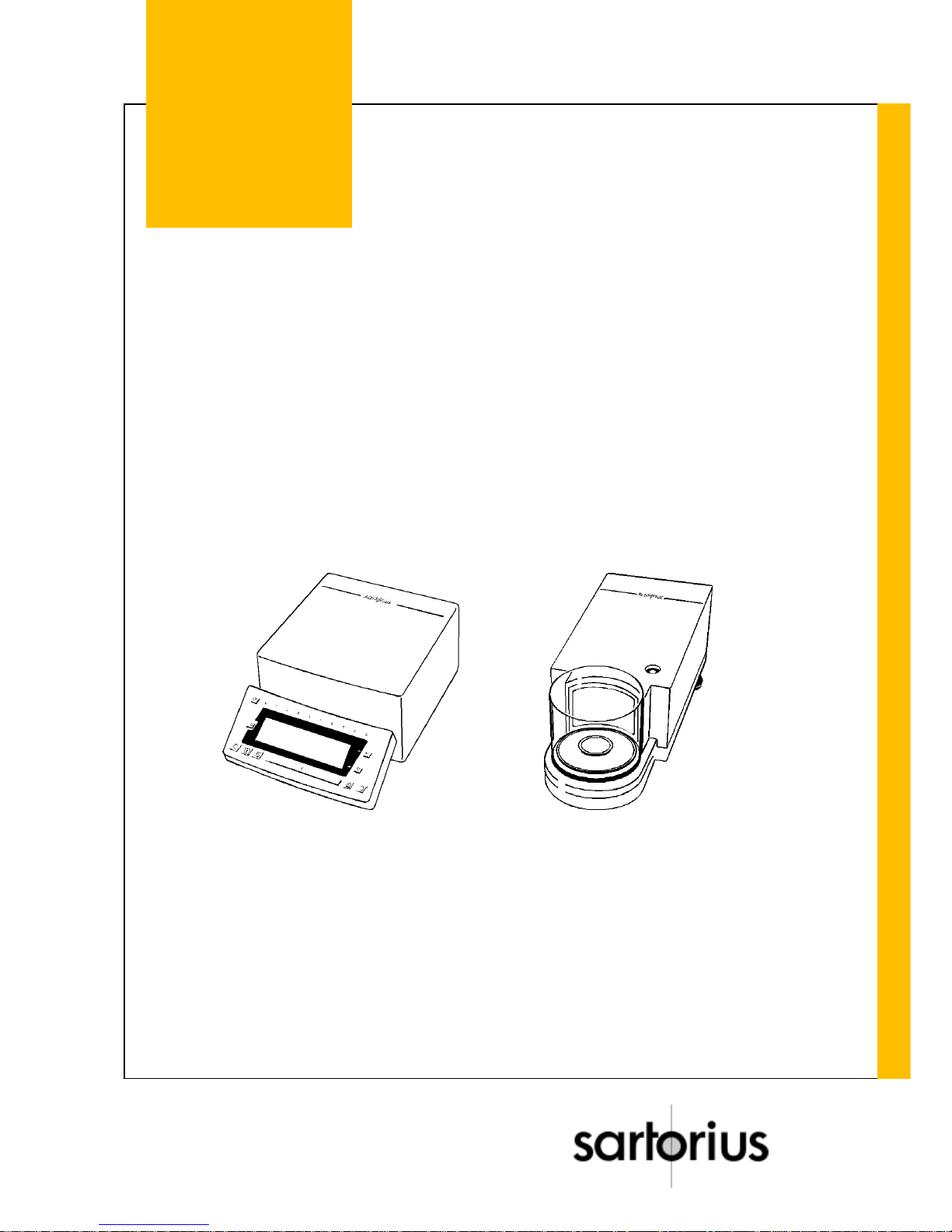
Sartorius Balance
Service Manual
MC 5
Page 2

Contents Page
Exploded-View Diagram 1 ......................................................................................................................... 4
Exploded-View Diagram 2 ......................................................................................................................... 6
Exploded-View Diagram 3 ......................................................................................................................... 8
Exploded-View Diagram 4 ....................................................................................................................... 10
Exploded-View Diagram 5 ....................................................................................................................... 12
Additional Service Tools and Equipment ................................................................................................. 14
Accompanying Literature......................................................................................................................... 14
General Information................................................................................................................................. 15
Installation Instructions............................................................................................................................ 16
Application Programs ........................................................................................................... ...................17
Key Functions ......................................................................................................................................... 18
Display Overview..................................................................................................................................... 18
Accessing the Balance Operating Menu and Setting Menu Codes ......................................................... 19
Displaying the Hardware and Software Version of the MC5 Microbalance ............................................. 20
Displaying the Model Name and the Serial Number................................................................................ 20
Activating the BPI Mode.......................................................................................................................... 21
Standard Service Tools and Equipment - Repair Policy.......................................................................... 22
Adjustment Data Sheet ........................................................................................................................... 22
Adjusting the Microbalance ..................................................................................................................... 23
Adjustment Sequence ............................................................................................................................. 23
Reproducibility......................................................................................................................................... 24
Null Indicator ........................................................................................................................................... 25
Checking the Null Indicator ..................................................................................................................... 25
Preload .................................................................................................................................................... 25
Checking and Adjusting the Preload ....................................................................................................... 25
Checking and Adjusting the Overload Stops ........................................................................................... 25
Indifferent Equilibrium.............................................................................................................................. 26
Checking the Indifferent Equilibrium (Tilt)................................................................................................ 26
Adjusting the Indifferent Equilibrium ........................................................................................................ 26
Off-Center Load (Eccentricity)................................................................................................................. 27
Checking the Off-Center Loading Tolerances ......................................................................................... 27
Adjusting the Off-Center Loading Tolerances ......................................................................................... 27
3-Point Coarse Adjustment ..................................................................................................................... 27
5-Point Fine Adjustment ..........................................................................................................................27
Linearity................................................................................................................................................... 28
External Linearization .............................................................................................................................. 28
Checking the Linearity............................................................................................................................. 28
Adjusting the Linearity ............................................................................................................................. 29
External Calibration ................................................................................................................................. 30
Overwriting the Internal Linearity Weight................................................................................................. 31
Overwriting the Internal Calibration Weight ............................................................................................. 32
Internal Calibration ........................................................................................................... ....................... 33
Internal Self-Calibrating Function ............................................................................................................ 33
Page 3

Description of the Microbalance .............................................................................................................. 34
Electronics............................................................................................................................................... 35
Main PCB (Exchanging) .......................................................................................................................... 35
Analog PCB (Exchanging)....................................................................................................................... 35
System PCB (Exchanging; Null Indicator Interface) ................................................................................ 35
Data Output PCB .................................................................................................................................... 35
Weight Servomotor PCB ......................................................................................................................... 35
Draft Shield PCB ..................................................................................................................................... 35
System Connector PCB ..........................................................................................................................35
Power-On Routine and Error Messages.................................................................................................. 36
Error Messages....................................................................................................................................... 36
Draft Shield ............................................................................................................................................. 38
Cleaning the Draft Shield......................................................................................................................... 38
Disassembling the Draft Shield Base Unit....................................................................................... ........ 38
Disassembling the Draft Shield Bearing .................................................................................................. 39
Checking and Adjusting the Draft Shield Bearing.................................................................................... 39
Overview of the Balance Operating Program .......................................................................................... 40
Page 4
4 SARTORIUS MC 5 Balance Stand 1/94
MC 5
Exploded - View Diagram 1
Page 5

Stand 1/94 SARTORIUS MC 5 Balance 5
MC 5
Index Designation
101 Top part of housing
102 Shielded enclosure
103 Guide
104 Main printed circuit (PCB)
105 Data output port (interface card)
106 Bracket
107 Analog PCB
108 Space rod
109 Ground plate
110 Leveling foot
111 Display housing
112 Display PCB module
113 Frame for switch pad
114 Switch pad
115 Angular cover plate
116 Holder
117 Cover plate
118 Mylar-backed strip conductor cable
119 Plate
Page 6
6 SARTORIUS MC 5 Balance Stand 1/94
MC 5
Exploded - View Diagram 2
Page 7

Stand 1/94 SARTORIUS MC 5 Balance 7
MC 5
Index Designation
201 Top part of housing
202 Draft shield
203 Weighing pan
204 Protective shield plate
205 Disassembling the Draft Shield Base
206 Groundtub
Page 8
8 SARTORIUS MC 5 Balance Stand 1/94
MC 5
Exploded - View Diagram 3
Page 9

Stand 1/94 SARTORIUS MC 5 Balance 9
MC 5
Index Designation
301 Cover plate
302 Enclosure frame
303 Space rod
304 System PCB
305 Level indicator
306 Leaf spring fastener
307 Leveling foot
308 Gasket
309 Disk
310 Retaining plate
311 Weight servomotor PCB with system sensor cable
312 Eccentric cam
313 Code disk
314 Drive (servomotor)
315 Lever
316/17 Ball
318 System connector PCB
319 System Disk
320 System
Page 10
10 SARTORIUS MC 5 Balance Stand 1/94
MC 5
Exploded - View Diagram 4
Page 11

Stand 1/94 SARTORIUS MC 5 Balance 11
MC 5
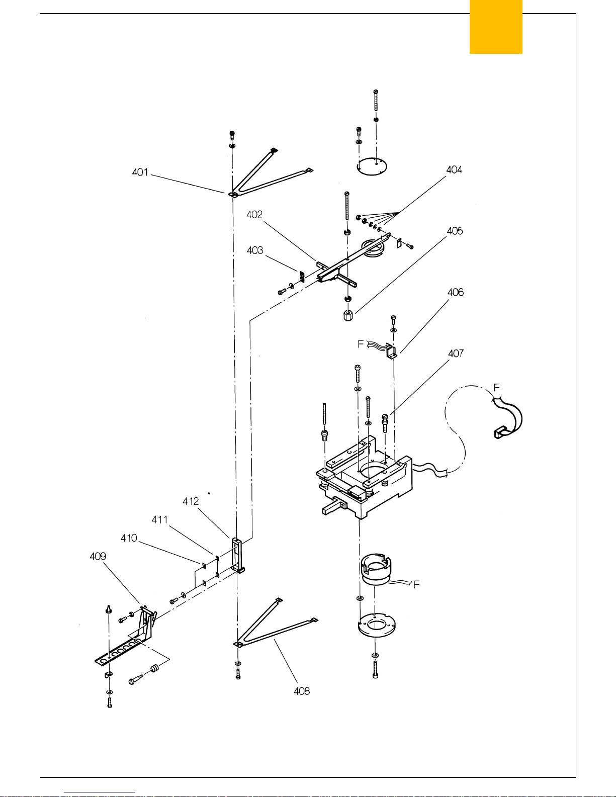
Index Designation
401/08 Guides
402 Lever, factory premounted
403 Leaf spring
404 Preload weights
405 Indifferent equilibrium weight
406 Null indicator subassembly, complete
407 Screw with special thread
409 Cantilever, complete
410 Clamping plate
411 Linkage flexure
412 Linkage
Page 12
12 SARTORIUS MC 5 Balance Stand 1/94
MC 5
Exploded - View Diagram 5
Page 13

Stand 1/94 SARTORIUS MC 5 Balance 13
MC 5
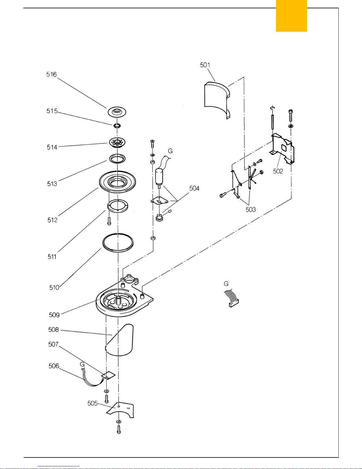
Index Designation
501 Curved panel for draft shield
502 Drive
503 Lever
504 Sensor cable (attached to draft shield PCB)
505 0-ring
506 Bearing ring
507 Centering ring
508 Support disk for bearing shell
509 Bearing shell
510 Thrust ring
511 Nut
512 Cover plate
Page 14

14 SARTORIUS MC 5 Balance Stand 1/94
MC 5
Additional Service Tools and Equipment
To service and repair the microbalance, set it up in a clean, stable work area that is free of vibrations and
drafts, and use the appropriate tools.
In addition to your regular tools, you will need the following special tools to work on the SARTORIUS
MC5 Microbalances:
No. of Units/Set Designation Order No.
1 Digital voltmeter, 4 ½ digits (e.g., Beckmann) 6738-62
1 2-channel oscilloscope, 20 MHz
1 Constant voltage source (e.g., Analogic AN 3100)
Weights and weight sets required:
1 E1 weight set if a PSION or a PC CAS prg. is not available
1 E2 weight set if a PSION or a PC CAS prg. is not available 6713-001
1 Weight, 1 g, E1
1 Weight, 5 g, E1
Caution!
Do not attempt to repair mechanical system; return microbalances with mechanical defects to our
International Service Headquarters in Goettingen, Germany.
To repair SARTORIUS MC5 Microbalances, considerable experience, completion of the
microbalance service course in Goettingen, Germany, and all special tools are required. Repair
attempts by non-authorized persons must therefore be avoided. Repair of balances by anyone other
than an authorized SARTORIUS service technician will result in the loss of all warranty coverage.
Accompanying Literature
The Sartorius Micro Instruction Manual, publ. no. WMC6011-e93091, contains these sections:
Installation Instructions
How to Operate the Balance
Balance Operating Menu
Application Programs
Interface Description
Specifications
Page 15

Stand 1/94 SARTORIUS MC 5 Balance 15
MC 5
11
12
13
7
5
8
9
10
7 1
17 2
3
16
4
15 5
6
14
General Information
The MC5 microbalance consists of a weighing cell and a display unit.
1 Draft shield 11 Male connector on display unit
2 Weighing cell 12 Data interface port
3 Level indicator
4 Weighing pan 13 AC jack
5 Leveling foot 14 Menu access switch
6 Protective shield plate
7 Manufacturer’s label (on the underside of the balance) 15 Key pad
8 Lug for attaching an anti-theft locking device 16 Metrological ID label ("stamp-/type
approved“ models: verified for trade)
9 Male connector on weighing cell 17 Display unit
10 Terminal for equipotential bonding conductor
Page 16

16 SARTORIUS MC 5 Balance Stand 1/94
MC 5
Installation Instructions
Important Note:
1. Use only the 7.5 DC
power supply, order no. 6971172 EURO or
order no.6971173 US/CDN
Do not use any other type of power supply or AC adapter;
otherwise this could cause problems with instability or drift!
2. Position the equipment to provide the required access for
operation.
Place the weighing cell on the left or the right of the display unit.
3. Mount the draft shield so that the periphery engages the
projected rim.
4. Attach the cable so that both units are directly connected without
the cable being kinked.
5. Level the weighing cell using the level indicator.
Page 17

Stand 1/94 SARTORIUS MC 5 Balance 17
MC 5
6. ERROR 235:
The display unit and the weighing cell constitute a single unit, as
programmed by the software. If you connect a display unit or
weighing cell of a different MC5 microbalance, you will obtain
the error message ERROR 235.
7. After initial installation, a power failure or opening the weighing
cell, allow the microbalance unit to warm up for at least 5-6
hours.
8. Whenever possible, use certified E1 weights.
Observe the weight tolerances when adjusting the microbalance
and overwriting the internal linearity or calibration weights.
(A 5g Class E1 weight has a tolerance of ±15µg)
(A 5g Class E2 weight has a tolerance of ±50µg)
9. You should set up the weighing cell on a sturdy balance table
that has a stone slab surface. Avoid exposing the microbalance
to extreme ambient conditions: heat radiation - temperature
fluctuations - drafts - vibrations - chemically aggressive
environments - high humidity. The microbalance is not allowed
to be operated in hazardous areas/locations.
Weighing System: The MC5 features a weighing system that is specially designed
for this microbalance, has a weighing capacity of 5 g with a
readability that is accurate to 1 µg over the entire range, and
does not require any internal tare weights. The weighing system
allows direct weight compensation.
The total resolution is 5 million digits.
Electronic Circuitry: The MC1 electronic circuitry has been adapted for this
microbalance (similar to the RC electronic circuitry).
Application Programs: Mass unit conversion by toggling between units; „EUREKA“ air
buoyancy correction program; differential weighing and
backweighing; diameter determination; tare memory / net-total;
weighing in percent; over/under checkweighing (classification,
filling); parts counting; GLP / GMP records/printouts
Built-in Interface Port: RS-232 C-S / V24-V28, RS-423 /V 10; 7-bit; even, mark, odd or
space parity; transmission speed: 150...19,200 baud; 1 or 2
stop bits; software/hardware handshake
Page 18

18 SARTORIUS MC 5 Balance Stand 1/94
MC 5
Key Functions:
on/off key
deletes or interrupts program runs and confirms that a changed menu code has been stored
key - displays/outputs info and stored values
tare control - zeros the display
weighing range toggle key
print key
function key for activating the first program application or calibration functions
function key for activating the second program application
draft shield function key - open toward the >> left <<
draft shield function key - open toward the >> right <<
View of the Display and Keypad:
0 - 9 keys (numeric keys)
. decimal point
Page 19

Stand 1/94 SARTORIUS MC 5 Balance 19
MC 5
Accessing the Balance Operating Menu and Setting Menu Codes
- Using the key, turn the balance off and back on again.
- While all segments are displayed, press the key.
- If >> -L- << is displayed, change to >> -C- << using the menu
access key to unlock the menu.
- To select the desired number, press
the key to increase or
the key to decrease the number.
- To select the desired place - left - center - right - press
the key to move to the left
the key to move to the right.
- Press the key to confirm the code
entered; a >> ° << appears after the code.
For example, to assign >> 2-1-4° << to the key
(see „Balance Operating Menu“ in the instruction manual),
set >> 9-1° << to reset all parameters to the factory settings
(default settings).
- To store the code, exit the program by pressing the key.
- Reset the menu access switch back to "locked“ indicated by
>> -L- <<.“
- If you do not want to save changes to the menu codes, exit from
the menu by pressing
the key.
Page 20

20 SARTORIUS MC 5 Balance Stand 1/94
MC 5
Displaying the Hardware and Software Version of the MC5
Microbalance
- Turn the microbalance off and back on again using the key.
- While all segments are displayed, briefly
press the key.
- The display shown on the left will appear for approx. 3 sec.
- The first two numbers show the hardware generation; the last
two, the software version.
- The balance will then return to its standard weight display mode.
Displaying the Model Name and Serial Number
- Turn the microbalance off and back on again using the key.
- While all segments are displayed, briefly press
the key.
- Model Name:
- Mod MC5 appears in the display shown on the left.
- Press the key.
- Serial Number:
- The serial number of the particular MC5 microbalance is
indicated in the display shown on the left.
- Then press the key, and the balance will return to the
standard weight display mode.
Page 21

Stand 1/94 SARTORIUS MC 5 Balance 21
MC 5
Activating the BPI Mode
To be able to work with the PSION server or the PC CAS program, change the communications protocol
for the interface to the BPI mode = Binary Protocol Interface, e.g., for linearization or diagnosis.
- Unplug the power supply and open the balance housing (Index
10).
- Plug the power supply back into the microbalance, and turn on
the microbalance using the key. mc-t-on.tif key. Wait for the
microbalance to complete the self-test; i.e., until 0.000mg is
displayed.
- Afterwards, plug the red jumper (short-circuit connector
located on the digital PCB 104) into the BPI position as shown
on the left.
- This closes a 12-volt circuit to the MC1 processor, which
disables the EEPROM’s write-protect status.
- The full-segment display test will run in regular cycles.
- Wait for at least 3 cycles, after which the balance will be in the
BPI mode.
- Afterwards, plug the jumper back into its original SBI position.
The balance will automatically revert to the standard weighing
mode.
Important Note:
- Turn off the microbalance using the key.
- Disconnect the microbalance from AC power.
- Close the balance housing.
- Plug the microbalance back into AC power and turn it on using
the key.
- Now the microbalance is ready to work with the MC1 server or
the CAS program for PCs in the BPI mode.
- After operating the microbalance with the PSION server or using
the PC CAS program, make sure to reset the interface mode by
software command to SBI = Sartorius Balance Interface:
PSION = Close
PC CAS = Log off
Otherwise, peripheral devices will not run on the microbalance’s
RS-232 interface port (ERR 30 will appear).
Page 22

22 SARTORIUS MC 5 Balance Stand 1/94
MC 5
Standard Service Tools and Equipment - Repair Policy
For diagnosis, adjustment or PCB exchange, you will need the following:
PSION server with the repair Datapack version 4.0 or Datapack version 4.2
or higher, as well as PC CAS program version 7.1 or higher.
Do not attempt to repair mechanical subassemblies; return
microbalances with mechanical defects to our International Service
Headquarters in Goettingen, Germany.
To obtain special authorization to repair mechanical defects, you are required
to have completed an intensive training course in Goettingen, Germany.
Until July, 1994, you are required to obtain special permission from the WSV
International Service Support Dept. to perform such repair work.
ADJUSTMENT DATA SHEET
for MC5 Microbalances
Balance Model MC5
Capacity /
range level
5 g
Readability 0.001mg
Reproducibility <=± 0.001mg
Linearity <=± 0.004mg
Calibration
weight
5 g / E1
Off-center
test weight
5 g
ø = 8mm
Off-center
test area
at the edge
of the pan
off-center
tolerance
<=± 0.007mg
Preload
test weight
0 g
Preload
voltage
-450...-550mV
Page 23

Stand 1/94 SARTORIUS MC 5 Balance 23
MC 5
Adjusting the Microbalance
Preparation:
Set up the microbalance on a stable surface, such as a balance
table with a stone slab. Level the weighing cell using the level
indicator, and allow the microbalance to warm up for at least 6
hours.
Avoid exposing the microbalance to extreme ambient conditions:
heat radiation - temperature fluctuations - drafts - vibrations chemically aggressive environments - high humidity.
The microbalance is not allowed to be operated in hazardous
areas/locations.
Adjustment Sequence
Check and, only if absolutely necessary, adjust the following:
1. Reproducibility
2. Null indicator
3. Preload
4. Indifferent equilibrium
5. Off-center load
6. External linearity
7. External calibration
8. Internal linearity weight (overwrite)
9. Internal calibration weight (overwrite)
Page 24

24 SARTORIUS MC 5 Balance Stand 1/94
MC 5
Reproducibility
Checking the Reproducibility:
- Before you check the reproducibility, be sure to observe the
following:
a. The conditions specified on page 22 of this Service Manual must
be met.
b. Make sure that code >> 1-6-1 << for Auto Zero has been set (for
instructions, see the section entitled „Accessing the Balance
Operating Menu and Setting Menu Codes“ on page 19 of this
manual).
To check the reproducibility, change the load on the pan 10 times using a 5g weight as described in the
following:
- Use the long anti-magnetic forceps.
- Unload the weighing pan. Close the draft shield by pressing
. After approx. 10 sec., 0.000mg will be displayed.
- Load 5g weight. Close the draft shield; once the readout has
stabilized, write it down.
- Remove the weight. Close the draft shield; once the readout
has stabilized, write it down.
- Repeat this test 10 times.
You can connect a printer, model YDP 02, to the microbalance in order to print out the values displayed
instead of writing them down.
If the standard deviation is >= 1 , you have to check and clean the weighing cell.
If the reproducibility error cannot be eliminated by cleaning the weighing cell, the weighing system is
defective, and the microbalance must be returned to the factory in Goettingen, Germany.
Page 25

Stand 1/94 SARTORIUS MC 5 Balance 25
MC 5
Null Indicator
Checking the Null Indicator:
The null indicator has to be re-adjusted only if the lever does
not stabilize symmetrically between the two beam overload
stops. It is unlikely that the null indicator subassembly will
become mis-aligned on its own.
Checking and Adjusting the Overload Stops:
The upper and lower stops must be adjusted so that the lever
can stabilize symmetrically between them.
When the lever has stabilized, you can measure approx. - 6V at
pin 6 of IC 303 (null indicator output) on the system PCB.
When you move the lever toward the upper and lower stops, the
voltage reading on the digital voltmeter should change by
approx. ± 1 V.
To adjust the beam overload stops, slightly turn the stop screw
as follows:
- lower stop - adjust the screw located between the null
indicator and the magnet cover
- upper stop - adjust the screw located on the rear section of
the magnet cover
Adjust the catch pin of the lever in the magnet cover so that the
lever can move freely.
A build-up of dirt on the coil or foreign objects on the null
indicator will cause the balance readouts to be non-reproducible.
Make sure that the stops are clean (no dirt film); if
necessary, use alcohol to clean them.
Preload
Checking the Preload:
With the weighing pan in place, the microbalance, when
unloaded, must generate a voltage reading of - 500mV ±50mV
on the digital voltmeter; at maximum load, it must generate
approx. 6.35V (unidirectional control circuit).
Adjusting the Preload:
Allow the beam to stabilize.
The preload weights (M 1.4 nuts and washers) are secured by
thescrew fastener which is located on top of the null indicator
flag.You can change the preload voltage by adding or removing
the washers.
Page 26

26 SARTORIUS MC 5 Balance Stand 1/94
MC 5
Indifferent Equilibrium
Checking the Indifferent Equilibrium (Tilt):
- Required only after you have worked on the weighing system
Purpose: Slight tilting of the weighing system must not cause the display to vary by more than ± 5 d !
- Unload the weighing pan and tare the microbalance.
- Level the microbalance using the level indicator and tare.
- Tare the microbalance. Then check the „front-to-back“ level.
- Tilt the microbalance so that the level indicator shows and write down the value displayed.
- Re-level the microbalance so that the circle in the level indicator returns to the original centered
position.
- Tare the microbalance. Then check the „right-to-left“ level.
- Tilt the microbalance so that the level indicator shows and write down the value displayed.
- Re-level the microbalance so that the circle in the level indicator returns to the original centered
position.
The values displayed must be within the tolerances ( ±5d ).
Adjusting the Indifferent Equilibrium:
As a rule, this is hardly ever necessary.
--> All microbalances are adjusted at the factory. Any substantial variation is due to a deeper
underlying cause. In this case, you should return the microbalance to the factory in Goettingen,
Germany, whenever possible.
- You can adjust the indifferent equilibrium on the „right-to-left“ level
through the closed cover (see diagram on the left) by using the set
screw 5 on the system support.
- Check the indifferent equilibrium by following the procedure described
above.
- Adjust the equilibrium by turning the set screw.
- Read off the display and repeat this procedure until the readout is
within the tolerances (± 5d).
Caution! Always use the special tool to lock the lever beam first before loosening the indifferent
equilibrium weight on the lever in order to adjust it.
Therefore, the weight cannot be adjusted without using the appropriate tool!
- Check the „front-to-back“ indifferent equilibrium by following the procedure described above.
- Read off the display and repeat this procedure until the readout is within the tolerances listed below:
Zero point error ±0.000005g
Sensitivity error for 5g ±0.000005g
- If the "!front-to-back“ indifferent equilibrium is out of tolerance, return the microbalance to Sartorius
Service Headquarters in Goettingen, Germany.
Page 27

Stand 1/94 SARTORIUS MC 5 Balance 27
MC 5
Off-Center Load (Eccentricity)
Checking the Off-Center Loading Tolerances (Eccentricity Test):
Check the off-center loading toleranzes ("corner load“/eccentric
loading error) at the 5 points shown in the diagram on the left.
Off-center test weight: 5g ø: approx. 8mm
Off-center test area: up to the edge of the weighing pan
Off-center tolerances: ± 0.007mg
If the values measured are out-of-tolerance, re-adjust the off-center
load.
Important Note:
If the off-center loading errors exceed the tolerances, check
the weighing system very carefully (reproducibility / visual
inspection).
Excessive off-center loading errors (> 500 d) indicate that the
weighing system is defective.
In this case, return the microbalance to the factory in
Goettingen, Germany.
Adjusting the Off-Center Loading Tolerances:
Before you begin to make this adjustment, remove the housing
cover from the weighing system.
Adjust the off-center loading tolerances in two steps:
- 3 Point (Coarse Adjustment):
For errors of approx. 50d to approx. 500d.
For coarse adjustment, use the set screws marked 3 and 4.
- 5 Point (Fine Adjustment):
For errors up to approx. 50d.
For fine adjustment, use the set screws marked 1 and 2. Adjust
them by only one complete turn at the most.
For the 1st step, measure the off-center loading error at 3 points.
Following coarse adjustment, measure the off-center loading error
at 5 points and perform fine adjustment, if necessary ( see top
diagram).
Page 28

28 SARTORIUS MC 5 Balance Stand 1/94
MC 5
Linearity
External Linearization
Note: Linearization can be done in 3 different ways:
1. as described in this service manual
2. using the PSION server or
3. using the CAS program written for personal computers and laptops
However, you should use only the PSION server or the CAS program written for PCs and laptops to
check and adjust the linearity of this microbalance.
Checking the Linearity:
- (The values displayed for a 1g test weight at various points along the weighing range must be equal
± 4d).
- When unloaded, the microbalance must display 0.000mg; if not, press the key.
- Place a 1g weight (test weight) on the weighing pan, close the draft shield, and write down the value
displayed.
- Remove the 1g weight from the pan.
- Place an approx. 1g weight on the pan to generate a load, close the draft shield, and press the
key.
- Add the test weight to the pan, close the draft shield, wait for the readout to stabilize, and write down
the readout.
- Remove the test weight from the pan.
- Now add another 1g weight to the pan to generate a preload of approx. 2g, close the draft shield, and
press the .
- Then place the test weight on the pan, close the draft shield, and write down the value displayed.
- Remove the test weight from the pan.
- Next, add another 1g weight to the pan to generate a preload of approx. 3g, close the draft shield, and
press the .
- Then place the test weight(s) on the pan, close the draft shield, and write down the value displayed.
- Remove the test weight(s) from the weighing pan.
- Next, place another 1g weight on the pan to generate a preload of approx. 4g, close the draft shield,
and press the key.
- Then place the test weight on the pan, close the draft shield, and write down the value displayed.
- Remove the weights (preload and test weights).
Important Note:
- The differences in the absolute values displayed may not exceed the tolerances given in the
"Adjustment Data Sheet“ (see page 22).
Important Note:
The linearity tolerance listed in the Adjustment Data Sheet is the average of 10 individual weighing
operations. Because of the spread of the measured values, the allowable variation in the linearity for
an individual weighing operation is approximately 2 times higher.
If the deviations are greater than the allowable tolerances, you will need to adjust the linearity.
Page 29

Stand 1/94 SARTORIUS MC 5 Balance 29
MC 5
Adjusting the Linearity:
Important Note:
Whenever possible, linearize the microbalance only by using the PSION server or the Sartorius CAS
program written for personal computers and laptops.
- Set menu code >> 1-12-1 << - external linearization accessible on the microbalance (see page 40 of the "Overview of the
Balance Operating Program“ aand page 19 "Accessing the
Balance Operating Menu").
- When the display shows 0.000 mg, hold down the key for
more than 3 sec. You will see the display shown on the left.
- Use the key to „scroll“ through the menu until >> L.E. <<
appears in the upper right-hand corner.
- Tare the microbalance using the key and press the key
to activate the linearization routine.
- The first linearity weight is now displayed.
- If necessary, use the numeric keys to enter a new, accurate
weight 5.0000xx (see Weight Certificate to enter the correct
value).
Important Note:
The microbalance will accept only a weight that is within a tolerance of approx. 2% of the factoryprogrammed linearity. You can set the microbalance for greater linearity variations only using the PSION
server (approx. 8% of the factory-programmed linearity) or the CAS program for PCs and laptops (in this
case, the linearity is adjustable from 0 to 100% of the factory-programmed value).
- Open the draft shield.
- Center the required weight on the pan and close the draft shield.
- After the weight has been accepted, the next linearity weight will
be displayed.
- Center the required weight on the pan and close the draft shield.
- Follow the same procedure outlined above to have all linearity
points recalled and the new weights accepted and stored by the
microbalance.
- At the end, you will be prompted to unload the microbalance.
- After the zero point has been stored, the microbalance will return
to the standard weighing mode.
- Now check the linearity again.
- At the end of the linearization routine, reset the menu code to
>> 1-12-2 << (external linearization - access denied).
For directions on how to overwrite the internal linearity weight, see page 31.
Page 30

30 SARTORIUS MC 5 Balance Stand 1/94
MC 5
External Calibration
Important: External calibration should be done only in exceptional cases
because calibration using internal weights is more accurate, as a rule. In
addition, the weights used to calibrate the microbalance at the factory in
Goettingen usually have a higher accuracy than do the external weights
normally available.
If you opt for external calibration, use external calibration weights with tolerances that are equal to or
better than accuracy class E2 (± 0.050mg for 5g) or E1 (± 0.015mg for 5g).
Note:
External calibration can be done in 3 different ways:
1. as described in this service manual
2. using the PSION server or
3. using the CAS program for personal computers and laptops
Important Note:
The microbalance will accept only a weight that is within a tolerance of approx. 2% of the factoryprogrammed value. You can set the microbalance for greater variations only using the PSION server
(approx. 50% of the factory-programmed calibration weight) or the CAS program written for PCs and
laptops (in this case, the calibration weight is adjustable from 0 to 100% of the factory-programmed
value).
However, you should use only the PSION server or the CAS program for PCs and laptops to check and
adjust the calibration weight of this microbalance.
- Unload the pan and press the key (ERR 02 see page 36).
- When the display shows 0.000000g, hold down the key for
more than 3 sec. You will see the display shown on the left.
- As soon as >> C.I. << appears, continue to press the
key until >> C.E. << is displayed.
- Tare the microbalance using the key and press the key
to activate the external calibration routine.
- The calibration weight is now displayed.
- If necessary, use the numeric keys to enter a new, accurate
weight 5.0000xx (see Weight Certificate to enter the correct
value).
- Center the required weight (5g) on the pan and close the draft
shield.
- After the calibration weight has been stored, the microbalance
will return to the standard weighing mode.
Page 31

Stand 1/94 SARTORIUS MC 5 Balance 31
MC 5
Overwriting the Internal Linearity Weight
Caution!
Do not overwrite the internal linearity weight for the sensitivity unless you have done the
following: run the three internal linearization and calibration routines and then take 3 readings
using a Sartorius external test weight (see Calibration Certificate for weights). Calculate the
average for these 3 test readings first, then calculate the allowable deviation range as follows: add
this average to the uncertainty of the test weight ±2 times the standard deviation of the
microbalance ± 4µg. If the average exceeds the allowable deviation, overwrite the linearity weight.
Example: (for a single test point):
- Conventional mass of the test weight listed on the Calibration Certificate: 2g + 0.022mg ±12µg
(±12µg is the uncertainty of the test weight)
- Standard deviation of the microbalance: ±1µg
- Allowable deviation: ±18µg
- The average of the values measured can range from 2.000004g to 2.000040g.
If the average of the values measured is greater, you are allowed to overwrite the internal linearity weight.
In this case, the attainable adjustment accuracy is approx. ± (the worst uncertainty of the weight used
+ 6µg).
Important Note:
If you need to overwrite the internal linearity weight on this microbalance, use only the PSION server or
the CAS program for PCs and laptops.
Procedure for Overwriting the Internal Linearity Weight:
Both the external linearizatio >> L.E. << and calibration >> C.E. << routines must be correctly
carried out before you begin with this procedure.
- Make sure that the menu code >> 1-13-1 << - internal
linearization accessible - has been set on the microbalance
(see page 40 of the „Overview of the Balance Operating Program“ for a list of the linearization menu codes).
- If you need to change the code, unlock the menu access switch
located on the rear panel of the microbalance.
- Then turn the microbalance off and back on again using the
key.
- While all segments are displayed (full-segment test), briefly
press the key.
- >> C.C. << or >> C.L. << now appears above the weight
readout in the upper right-hand corner.
- Press the key until >> C.L. << is displayed.
- Press to tare the microbalance first, then press to
activate the linearization routine for overwriting. >> C << will now
appear.
Page 32

32 SARTORIUS MC 5 Balance Stand 1/94
MC 5
- The internal linearity weights are now loaded and unloaded in
sequence by the servomotor. In the process, the weight value is
stored in the EEPROM of the microbalance processor.
Afterwards, the microbalance returns to the standard weighing
mode.
- At the end of the linearization routine, reset the menu code to
>> 1-13-2 << and lock the menu access switch.
Overwriting the Internal Calibration Weight
Caution!
Do not overwrite the internal calibration weight unless you have done the following: run the
internal linearization and calibration routines and then take 10 readings using a Sartorius external
test weight (see Calibration Certificate for weights). Calculate the average for these 10 test
readings first, then calculate the allowable deviation range as follows: add this average to the
uncertainty of the test weight ± the standard deviation of the microbalance ± 4µg. If the average
exceeds the allowable deviation, overwrite the internal calibration weight.
Example:
- Conventional mass of the test weight listed on the Calibration Certificate: 5g + 0.022mg
±15µg (±15µg is the uncertainty of the test weight)
- Standard deviation of the microbalance: ±1µg
- Allowable deviation: ±20µg
- The average of the values measured can range from 5.000002g to 5.000042g.
If the average of the values measured is greater, you are allowed to overwrite the internal calibration
weight.
In this case, the attainable calibration accuracy is approx. ± (the worst uncertainty of the weight used
+ 6 µg).
Important Note:
If you need to overwrite the internal calibration weight on this microbalance, use only the PSION server or
the CAS program for PCs and laptops.
Procedure for Overwriting the Internal Calibration Weight:
Important note: The microbalance must be accurately calibrated using a external >> E1 << weight set
or, better yet, using the PSION server before you begin with this procedure.
- Make sure that the menu code >> 1-10-1 << - internal calibration
accessible - has been set on the microbalance (see page 40 of
the "Overview of the Balance Operating Program“).
- If you need to change the code, unlock the menu access switch.
It is accessible when you remove the cap next to the AC jack on
the rear panel of the microbalance.
Page 33

Stand 1/94 SARTORIUS MC 5 Balance 33
MC 5
- Then turn the microbalance off and back on again using the
key.
- While all segments are displayed (full-segment test), briefly
press the key.
- >> C.C.<< or >> C.L.<< now appears above the weight readout.
- Press the key until >> C.C. << is displayed.
- Press to tare the microbalance first, then press to
activate the calibration routine.
The internal calibration weights are now loaded and removed in
sequence by the servomotor. In the process, the weight stored
in the EEPROM of the microbalance is overwritten by the weight
currently displayed. Afterwards, the microbalance returns to the
standard weighing mode.
- At the end of the calibration routine, reset the menu code to
>> 1-10-2 << and lock the menu access switch.
Internal Calibration:
- Make sure that the menu code >> 1-10-1 <<
- internal calibration accessible - has been set on the
microbalance.
- As soon as the readout has stabilized, press the key.
- Confirm by pressing the key, and >> C.I. << will be
displayed.
- The internal calibration weights are now loaded and unloaded in
sequence by the servomotor. In the process, the weight value is
stored in the EEPROM of the microbalance processor.
Afterwards, the microbalance returns to the standard weighing
mode.
- At the end of the internal calibration routine, reset the menu
code to >> 1-10-2 << and lock the menu access switch.
Internal Self-Calibrating Function:
- To activate the internal self-calibrating function (ISOcal), check
that menu code >> 1-15-3 << has been set.
- When the microbalance wants to self-calibrate, a balance
symbol will flash on the display, and the microbalance will then
perform automatic internal calibration.
- If a printer is connected to the microbalance, a record of this
process will be printed on hard copy (for GLP/GMP compliance),
depending on the menu code setting (see page 2-31 in the MC5
instruction manual).
Page 34

34 SARTORIUS MC 5 Balance Stand 1/94
MC 5
Description of the Microbalance:
The MC5 consists of two major units:
a. Weighing Cell
Located inside the weighing cell are the mechanical coil/beam
system, the servomotor subassembly for internal weight
application, the draft shield drive and bearing system, including the
following:
System connector PCB
(See page 8 Exploded-view diagram 3.....No.318)
System PCB
(see page 8 Exploded-view diagram 3.....No.304)
Weight servomotor PCB
(see page 8 Exploded-view diagram 3.....No.311)
Null indicator PCB
(see page 10 Exploded-view diagram 4.....No.406)
Draft shield PCB
(see page 12 Exploded-view diagram 5.....No.504)
b. Display Unit
The display unit houses the following components:
Main PCB
(see page 4 Exploded-view diagram 1.....No.104)
Analog PCB
(see page 4 Exploded-view diagram 1.....No.107)
Data output PCB
(see page 4 Exploded-view diagram 1.....No.105)
The LCD of the display unit is attached to the following:
Display PCB module
(see page 4 Exploded-view diagram 1.....No.111)
Page 35

Stand 1/94 SARTORIUS MC 5 Balance 35
MC 5
Electronics: The microbalance’s electronics consist of 9 printed-circuit
boards (PCBs) that have various functions depending on the
type of components mounted:
1. The main PCB contains the following:
Power supply, microcomputer, motor control subassembly,
menu switch and EEPROM IC106 for: menu functions,
adjustment, calibration, linearization, vibration filter settings,
temperature compensation for drift (creep), and codes relevant
to manufacturing operations.
To exchange this board, see item 4 of this section.
2. The following components are mounted on the analog PCB:
low-pass filter, temperature-compensating circuit, reference
voltage circuit, and the A / D converter, including the EEPROM
IC208 with the components for temperature compensation and
the temperature-compensating sensor.
To exchange this board, see item 4 of this section.
3. Located on the system PCB is an amplifier circuit for the null
indicator and the temperature sensor as well as the system
EEPROM IC107 with the serial number of the microbalance.
To exchange this board, see item 4 of this section.
Important Note:
4. Before exchanging a PCB mentioned in items 1-3, make sure to
save all EEPROM data by downloading them onto a PSION
server, PC or laptop!
5. The RS-232 port driver is on the data output PCB.
6. Photoelectric barriers are mounted on the servomotor PCB for
the internal weight and the draft shield PCB.
7. One transmitter diode and two receiver diodes are located on
the null indicator PCB.
8. The multicontact connectors listed below are mounted on the
system connector PCB:
A 20-pin connector is routed from the null indicator/interface
PCB, connector St. 22/23. (The connectors are abbreviated in
German as „St.“ below):
St.21 25-pin To computing (display) unit
St.28 10-pin To null indicator/system PCB
St.27 7-pin To weight servomotor PCB
St.29 9-pin To draft shield PCB
Display Module: Similar to the MC1 technology on RC models; with numeric key functions from 0...9.
Page 36

36 SARTORIUS MC 5 Balance Stand 1/94
MC 5
Power-On Routine and Error Messages
Once your have turned on the balance using the key, " 0.000 mg “ is displayed. This indicates that
the balance is ready to operate.
Error Messages
On the MC 5, error messages are indicated by a code number.
All codes for operating errors, including errors in the sequence of a function, have two-digit numbers.
Error codes for hardware errors have three-digit numbers.
The error codes enable you to identify the type of operating error.
Display Meaning Reason/Solution
Err 01 Display format overflow The weighing system is overloaded.
Err 02 Zero point error at the start Re-tare;
of the CAL routine check system.
Err 04 Control error during Check system for stability.
multiple calibration mode
Err 06 Internal calibration weight Check system. Return the microbalance
defective or not available to the factory, if necessary.
Err 10 1st tare memory disabled The tare functions are
when a value is stored in interlocked. Clear tare
2nd tare memory memory to enable the CF/ tare key.
Err 11 Attempt to store an invalid The readout was negative,
number in tare memoryfor example - check sample.
using TAR -F1/
Err 20 The ></ key was pressed For instance, you forgot
before an application to store a reference
program was initialized percentage for weighing in percent.
Err 21 Reference percentage or Code 2 3 1 is selected in the balance
reference piece count setting operating menu. Change this code
disabled, or this application to 2 3 2 or 2 3 3.
does not have a parameter mode
Err 22 Reference cannot be stored The weight is too light or
for weighing in percent or counting no sample is on the pan.
Err 23 Value cannot be stored No sample is on the pan or
for any particular application program the readout is negative.
Err 30 The print key was pressed Connect printer.
in the BPI mode; no printer on-line
Err 50 Converter error (TC range) Check system or return microbalance to the
factory in Goettingen.
Err 53 Temperature sensor circuit failure Check temperaturecompensating sensor or
return microbalance to the factory in Goettingen.
Err 54 Balance converter value below Check system.
the minimum limit Beam at lower stop.
Page 37

Stand 1/94 SARTORIUS MC 5 Balance 37
MC 5
Err 55 Balance converter value below
the maximum limit Beam at upper stop.
Err 62 Pressing the F1/ key is Follow correct operating
momentarily not allowed procedure.
Err 63 Pressing the F2/ key is not Follow correct operating
allowed procedure.
Err 64 Numeric entry is not allowed Follow correct operating procedure.
Err 70 Incorrect numeric entry Enter new value that is appropriate for the
microbalance’s weighing capacity/range levels.
Hardware Errors
Hardware error codes are displayed as long as the error persists. During this time, the error code is
output via the data interface port.
Err 210 Defective AOC interface Replace the PCB.
Err 220 EPROM checksum error Using the ON/OFF key, turn the microbalance
off, then back on again;
you may need to exchange the PCB.
Err 230 RAM read/write error Using the ON/OFF key, turn the microbalance
off, then back on again;
you may need to exchange the PCB.
Err 234 Checksum error in the battery-backed Leave microbalance plugged into AC current
RAM; rechargeable battery for approx. 12 hours to recharge battery.
completely drained or defective
Err 235 Display unit and weighing cell do not match
Err 237 EEPROM checksum error, Activate >>external linearization<< function
linearity range
Err 239 EEPROM checksum error Determine the
>>internal linearization weight<<
Err 241 EEPROM checksum error, Incorrrect software programming;
permanent area contact the International Service Support Dept.
for help.
Err 243 EEPROM checksum error, Turn microbalance off and back on;
menu area change menu access switch setting to
"Change“ and access menu.
Change code and exit from the menu using CF.
Err 247 EEPROM checksum error, Run calibration routine
calibration range by setting the appropriate
calibration menu code.
Err 249 EPROM checksum error, Determine the internal
calibration weight calibration weight.
Err 253 Checksum error, Run the air density
air density determination program.
Page 38

38 SARTORIUS MC 5 Balance Stand 1/94
MC 5
Draft Shield
Cleaning the Draft Shield
- Turn off the microbalance.
- Unplug the microbalance from line power.
- Remove the glass draft shield (202), the weighing pan (203), and
shield plate (204), including, if necessary, the cover plate (516) by
turning it by hand toward the left.
- Now the support disk (512) and the curved panel (501) are accessible
for cleaning.
- Use only a commercially available detergent or dishwashing liquid
heated to max. 95° Celsius to clean the draft shield (202).
- Afterwards, re-assemble the draft shield following the steps above in
reverse order.
- Place the glass draft shield on the base without tilting it so that the
periphery engages the protective rim.
Disassembling the Draft Shield Base Unit
- Turn off the microbalance.
- Unplug the microbalance from line power.
- Remove the glass draft shield, (202), the weighing pan (203), and the
shield plate (204).
- Carefully invert the weighing cell so that it rests on the top part of the
housing (201).
- Remove the 4 fastening screws (A) to detach the top part of the
housing (201).
- Remove the 4 fastening screws (B) to detach the draft shield base unit
(205).
- Holding the draft shield base unit (205) in place, turn the weighing
system right side up so that it rests on the leveling feet (307).
- Disconnect the sensor cable (506) from the plug that is located on the
left side of the system, and lift off the draft shield base unit (205).
- Now you can disassemble the draft shield bearing (see exploded-view
drawing 5 on page 12).
- Afterwards, re-assemble the draft shield bearing by following the steps
above in the reverse order.
- Important note: Make sure to insert the sensor cable (506) through
the slot of the system holding plate (319) without pinching the cable.
- Allow the microbalance to warm up briefly (wait approx. 30 minutes)
so that it will be ready to operate again.
Page 39

Stand 1/94 SARTORIUS MC 5 Balance 39
MC 5
Disassembling the Draft Shield Bearing
- Disassemble the draft shield base unit from the weighing system (see
"Disassembling the Draft Shield Base Unit“ on page 38).
- Remove the V-belt (508) from the drive (504).
- Detach the cover plate (516), the 14mm locknut (515) and the thrust
ring (514), and remove the support disk (512).
- Now you can exchange the bearing ring ((510) and the bearing shell
(513).
- It is important that the ball side of the bearing thrust ring (510) and the flat side of the bearing
shell (513) face upward.
- Position the support disk (512) on the adapter, which must be
centered with respect to the curved draft shield panel. Turn the disk
slightly until it rests completely flat. Press-fit the V-belt (508) in the
groove of the support disk (512).
- Unscrew the thrust ring (514) just until it has sufficient clearance.
Then place the V-belt (508) on the drive (504).
- Now attach the locknut (515) to the thrust ring (514). Hold the thrust
ring in place while tightening the locknut (515).
- Turn the support disk (512) by hand. If you hear a scraping sound
when you turn the disk, or if it is difficult to turn, slightly loosen the
thrust ring. In rare cases, you may need to adjust the sensor PCB
(507).
- Assemble the complete draft shield by following the steps listed above in the reverse order.
- Important note: Make sure to insert the sensor cable (506) through the slot in the system holding plate
(319) and plug in the connector. Check that none of the cables is jammed.
- Allow the microbalance to warm up briefly (wait approx. 30 minutes) so that it will be ready to operate
again.
Checking and Adjusting the Draft Shield Bearing
- Press the key.
If the draft shield does not open easily, slightly loosen the thrust ring
(514).
If the draft shield closes beyond the normal position, slightly retighten
the thrust ring (514).
To do so, hold the thrust ring in place while tightening the locknut
(515).
- Check that the speed of the draft shield movement is the same for
each direction.
- If this is not the case, you need only to remove the top part of the
housing (201) - see "Disassembling the Draft Shield Base Unit“) and
the screw on the right (502a) or on the left (502b); slightly move back
the angular retainers (502) of the curved panel (501); and retighten
the screw.
- Check the functioning of the draft shield movement again as described
above; if necessary, re-adjust.
- Close the weighing system by following the steps above in the reverse
order.
- Attach the cover plate (516), and mount the shield plate (204), the
weighing pan (203) and the draft shield (202).
- Allow the microbalance to warm up briefly (wait approx. 30 minutes) so that it will be ready to operate
again.
Page 40

40 SARTORIUS MC 5 Balance Stand 1/94
MC 5
Overview of the Balance Operating Program
1 Balance Operation
1 Ambient Conditions
1-1-1 Very stable (shortest response time)
1-1-2 Stable (short response time)
1-1-3 Unstable (long response time)
1-1-4 Very unstable (longest response time)
2 Application Filter
1-2-1 Standard weighing
1-2-2 Filling
3 Stability Range
1-3-1 0,25 digit
1-3-2 0,5 digit
1-3-3 1 digit
1-3-4 2 digits
1-3-5 4 digits
1-3-6 8 digits
4 Stability Symbol Delay
1-4-1 None delay
1-4-2 Short delay
1-4-3 Long delay
1-4-4 Extremely long delay
5 Tare Parameter
1-5-1 At any time
1-5-2 After stability
6 Auto - Zero Function
1-6-1 Auto - Zero on
1-6-2 Auto - Zero off
1st Range
7 Weight Units
1-7-1 o Selectable unit
1-7-2 g Grams
1-7-3 o Kilograms
1-7-4 ct Carats
1-7-5 lb Pounds
1-7-6 oz Ounces
1-7-7 ozt Troy ounces
1-7-8 tl Hon Kong taels
1-7-9 tl Singapore taels
1-7-10 tl Taiwanese taels
1-7-11 gr Grains
1-7-12 dwt Pennyweights
1-7-13 mg Milligrams
1-7-14 o Parts/pound
1-7-15 tl Chinese taels
1-7-16 m Mommes
Page 41

Stand 1/94 SARTORIUS MC 5 Balance 41
MC 5
1 Balance Operation
1-7-17 o Carats
1-7-18 t Tola
1-7-19 b Baht
1-7-20 m Mesghal
8 Display Mode Selection
1-8-1 Highest accuracy
1-8-2 Last numeral blanked when load changes
1-8-3 Rounding factor 2
1-8-4 Rounding factor 5
1-8-5 Rounding factor 10
1-8-6 1.0 % display accuracy
1-8-7 0.5 % display accuracy
1-8-8 0.2 % display accuracy
1-8-9 0.1 % display accuracy
1-8-10 0.05 % display accuracy
1-8-11 0.02 % display accuracy
1-8-12 0.01 % display accuracy
1-8-13 PolyRange function
9 External Calibration
1-9-1 Accessible
1-9-2 Access denied
10 Internal Calibration
1-10-1 Accessible
1-10-2 Access denied (key)
11 Sensitivity Test
1-11-1 Accessible
1-11-2 Access denied
12 External Linearization
1-12-1 Accessible
1-12-2 Access denied
13 Internal Linearization
1-13-1 Accessible
1-13-2 Access denied
14 Multiple Calibration Mode
1-14-1 Off
1-14-2 On
15 Auto - Calibr. and
Linearization
1-15-1 Off
1-15-2 Cal. status only
1-15-3 On
1-15-4 Auto-cal. + lin.on
16 Air Density Determination
1-16-1 Accessible
Page 42

42 SARTORIUS MC 5 Balance Stand 1/94
MC 5
2st Applications
2-1-1 No application
2-1-2 2 weighing ranges
2-1-3 3 weighing ranges
2-1-4 Counting
2-1-5 Weighing in percent
2-1-6 Backweighing
2-1-7 Diameter determination
2-1-8 Air buoyancy correction
2 F1 - Key Applications
2-2-1 No function
2-2-2 Tare memory
2-2-3 Over/under - net weight
2-2-4 Over/under - difference in weight
2-2-5 Intern. calibration
2-2-6 Calibration test
3 Parameter Mode
2-3-1 Access denied
2-3-2 In cycles (table)
2-3-3 In increments of 1
4 Clear Function with CF
2-4-1 Clear all keys
2-4-2 Clear F1 -> F2
2-4-3 Clear F1 or F2
5 Numeric Keys
2-5-1 Access denied
2-5-2 Accessible without +/- sign
2-5-3 Accessible with +/- sign
Page 43

Stand 1/94 SARTORIUS MC 5 Balance 43
MC 5
2st Range
3 Para. 1st Application
1 Weight Units
3-1-1 o Selectable unit
3-1-2 g Grams
3-1-3 o Kilograms
3-1-4 ct Carats
3-1-5 lb Pounds
3-1-6 oz Ounces
3-1-7 ozt Troy ounces
3-1-8 tl Hong Kong taels
3-1-9 tl Singapure taels
3-1-10 tl Taiwanese taels
3-1-11 gr Grains
3-1-12 dwt Pennyweights
3-1-13 mg Milligrams
3-1-14 o Parts/pound
3-1-15 tl Chinese taels
3-1-16 m Mommes
3-1-17 o Carats
3-1-18 t Tola
3-1-19 b Baht
3-1-20 m Mesghal
2 Display Mode Selection
3-2-1 Highest accuracy
3-2-1 Last numeral blanked when load changes
3-2-1 Rounding factor 2
3-2-1 Rounding factor 5
3-2-1 Rounding factor 10
3-2-1 1 % display accuracy
3-2-1 0.5 % display accuracy
3-2-1 0.2 % display accuracy
3-2-1 0.1 % display accuracy
3-2-1 0.05 % display accuracy
3-2-1 0.02 % display accuracy
3-2-1 0.01 % display accuracy
3-2-1 PolyRange function
Page 44

44 SARTORIUS MC 5 Balance Stand 1/94
MC 5
3st Range
3 Para. 1st Application
3 Weight Units
3-3-1 o Selectable unit
3-3-2 g Grams
3-3-3 o Kilograms
3-3-4 ct Carats
3-3-5 lb Pounds
3-3-6 oz Ounces
3-3-7 ozt Troy ounces
3-3-8 tl Hong Kong taels
3-3-9 tl Singapore taels
3-3-10 tl Taiwanese taels
3-3-11 gr Grains
3-3-12 dwt Pennyweights
3-3-13 mg Milligrams
3-3-14 o Parts/pound
3-3-15 tl Chinese taels
3-3-16 m Mommes
3-3-17 o Carats
3-3-18 t Tola
3-3-19 b Baht
3-3-20 m Mesghal
4 Display Mode Selection
3-4-1 Highest accuracy
3-4-2 Last numeral blanked when load changes
3-4-3 Rounding factor 2
3-4-4 Rounding factor 5
3-4-5 Rounding factor 10
3-4-6 1 % display accuracy
3-4-7 0.5 % display accuracy
3-4-8 0.2 % display accuracy
3-4-9 0.1 % display accuracy
3-4-10 0.05 % display accuracy
3-4-11 0.02 % display accuracy
3-4-12 0.01 % display accuracy
3-4-13 PolyRange function
5 Readout in Percent
3-5-1 Without decimal
3-5-2 1 decimal
3-5-4 2 decimals
3-5-4 3 decimals
Page 45

Stand 1/94 SARTORIUS MC 5 Balance 45
MC 5
3 Para. 1st Application
6 Backw.: Weighing Sequence
3-6-1 Individual weighing
3-6-2 Consec. indiv. weighing
3-6-3 Combined weighing
7 Backw.: Tara Weighing
3-7-1 Off
3-7-2 On
8 Backw.: 1st Calculated Value
3-8-1 Residue in grams
3-8-2 Residue in percent
3-8-3 Difference in grams
3-8-4 Difference in percent
9 Backw.: 2nd Calculated Value
3-9-1 Residue in grams
3-9-2 Residue in percent
3-9-3 Difference in grams
3-9-4 Difference in percent
4 Para. 2st Application
1 Over / Under Tolerance Limits
4-1-1 ± 0.1 %
4-1-2 ± 0.2 %
4-1-3 ± 0.5 %
4-1-4 ± 1.0 %
4-1-5 ± 1.5 %
4-1-6 ± 2.0%
4-1-7 ± 2.5 %
4-1-8 ± 3.0 %
4-1-9 ± 5.0 %
4-1-10 ± 10.0 %
2 Auto Output of OK Values
4-2-1 Off
4-2-2 On
3 Activation of Port Lines
4-3-1 Within checkweighing range
4-3-2 Always on
4-3-3 At stability + in ch. range
4-3-4 At stability
Page 46

46 SARTORIUS MC 5 Balance Stand 1/94
MC 5
5 Interface Parameters
1 Baud Rate
5-1-1 150 baud
5-1-2 300 baud
5-1-3 600 baud
5-1-4 1200 baud
5-1-5 2400 baud
5-1-6 4800 baud
5-1-7 9600 baud
5-1-8 19200 baud
2 Parity
5-2-1 Mark parity
5-2-2 Space parity
5-2-3 Odd parity
5-2-4 Even parity
3 Number of Stop Bits
5-3-1 1 stop bit
5-3-2 2 stop bits
4 Handshake Mode
5-4-1 Software
5-4-2 Hardware 2 characters after CTS
5-4-3 Hardware 1 character after CTS
6 Utilities
1 Data Output Parameter
6-1-1 Without stability
6-1-2 After stability
6-1-3 At stability
6-1-4 Auto print w/out stability
6-1-5 Auto print after stability
2 Auto Data Output
6-2-1 Stop with key
6-2-2 Not stoppable
3 Print Interval after
6-3-1 1 display update
6-3-2 2 display updates
6-3-3 5 display updates
6-3-4 10 display updates
6-3-5 20 display updates
6-3-6 50 display updates
6-3-7 100 display updates
4 Auto Tare after Data Output
6-4-1 off
6-4-2 on
Page 47

Stand 1/94 SARTORIUS MC 5 Balance 47
MC 5
7 Recording Printing Applications
1 Automatic Output of Parameters
7-1-1 Off
7-1-2 All Parameters
7-1-3 Main parameters only
2 Data Output Format
7-2-1 Without data ID code
7-2-2 With data ID code
3 Auto Tare Output / Printing
7-3-1 Last net weight
7-3-2 Total tare weight
4 Backweighing Rec. w/ Data Time
7-4-1 Off
7-4-2 Date only
7-4-3 Time only
7-4-4 Date and time
5 Backw. Rec. w / Tare_ Net weight
7-5-1 Off
7-5-2 Tare weight only
7-5-3 Net weight only
7-5-4 Tare and net weight
6 Backw. Rec. w / Residue
7-6-1 Off
7-6-2 Residue in g
7-6-3 Residue in %
7-6-4 Residue in g + %
7 Backw. Rec. w / Difference
7-6-1 Off
7-6-2 Difference in g
7-6-3 Difference in %
7-6-4 Difference in g + %
Page 48

48 SARTORIUS MC 5 Balance Stand 1/94
MC 5
8 Additional Functions
1 Access to Menu
8-1-1 Accessible
8-1-2 Readable
2 Acoustic Signal
8-2-1 On
8-2-2 Off
3 Key Functions
8-3-1 Accessible
8-3-2 Blocked
4 Universal - Switch
8-4-1 Print
8-4-2 Tare
8-4-3 Function 1 key
8-4-4 Function 2 key
8-4-5 Open/close draft shield
5 Power-On Mode
8-5-1 Off - on - standby
8-5-2 Off - on (battery op.)
8-5-3 On - standby
8-5-4 Auto. power on (remote control)
6 Display Backlighting
8-6-1 On
8-6-2 Off
8-6-3 Auto - off
7 Interface Port - Function
8-7-1 Data output
8-7-2 Data input
8 Auto Draft Shield
8-8-1 Off
8-8-2 Shut - function - open
8-8-3 Shut - delay - function - open
8-8-4 Shut - function
8-8-5 Shut - delay - function
9 Display Accuracy w. / Draft
Shield Auto Open. / Man. Adjus.
8-9-1 Highest accuracy
8-9-2 Rounding factor 2
8-9-3 Rounding factor 5
8-9-4 Rounding factor 10
8-9-5 Rounding factor 20
8-9-6 Rounding factor 50
8-9-7 Rounding factor 100
Page 49

Stand 1/94 SARTORIUS MC 5 Balance 49
MC 5
8 Additional Functions
10 GLP / GMP Printout / Record
8-10-1 Off
8-10-2 Only for cal. functions
8-10-3 Always on
9 Reset Function
9-1-1 Active
9-1-2 Off
 Loading...