

Page 1

Page 2

3
Sartorius
Research Series
Electronic Semi-Micro and
Analytical Balances
Installation and Operating Instructions
WRC 6001-e94013
Page 3
2
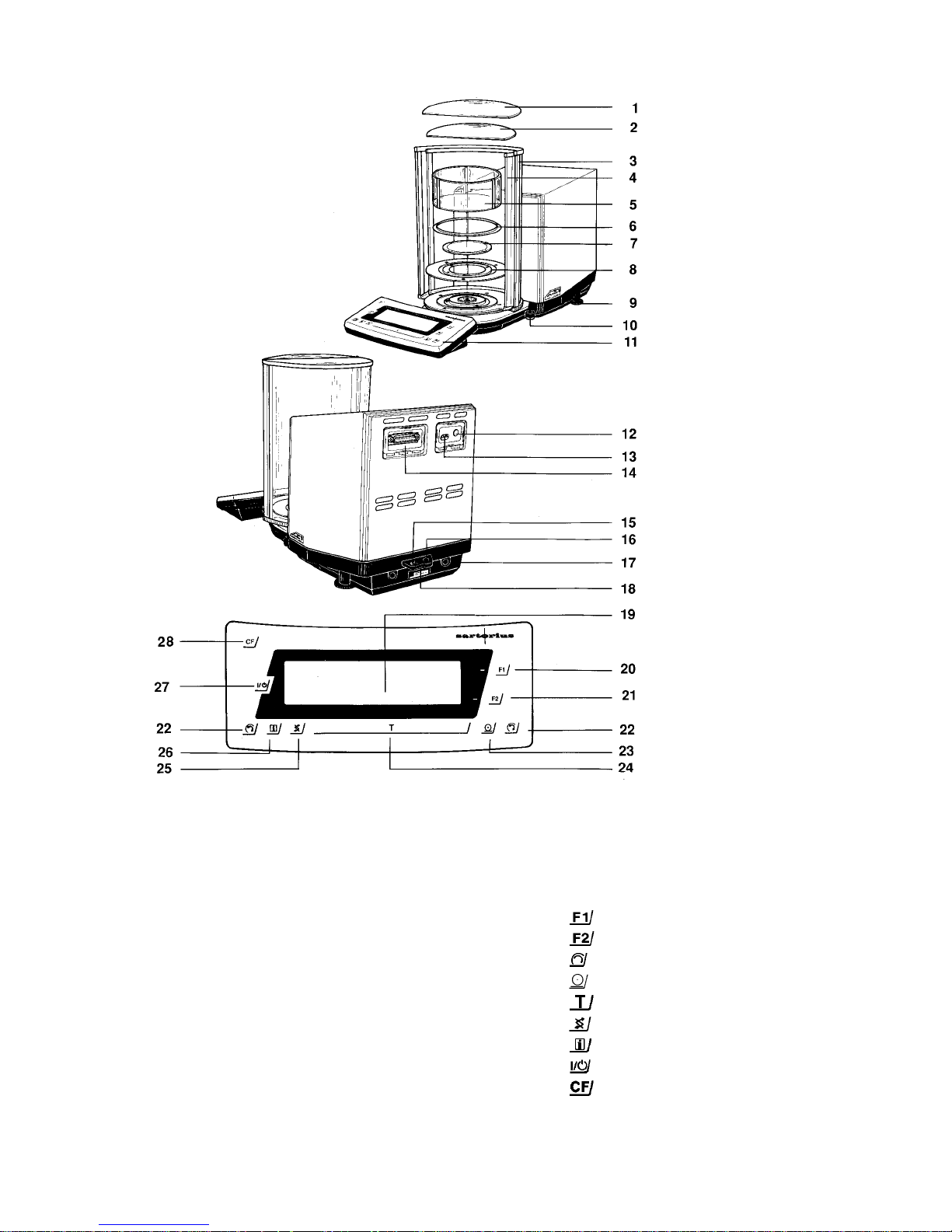
1 Large draft shield cover
2 Small draft shield cover
3 Exterior draft shield element, semi cylindrical
(can be moved by hand)
4 Interior draft shield door, semi cylindrical (can be
moved by motor control or by hand)
5 Interior weighing chamber draft shield (depending
on the balance model)
6 Protective ring
7 Weighing pan
8 Shield disk
9 Levelling food
10 Level indicator
11 Display unit
12 AC jack
13 Menu access switch
14 Data interface port
15 Terminal for connecting an equipotential bonding
conductor
16 Lug for attaching the antitheft locking device
17 Metrological label (only *D1-Models)
18 Manufacturer's label
19 Weight and Information display
20
- function key
21
- function key
22
- draft shield function key
23
- Print key (data transfer)
24
- Tare control
25
- toggle key
26
- Info key
27
- ON/Off key
28
- key
Page 4

3
Contents
Page
Warranty 4
Storage and Shipping Conditions 5
Transporting the Balance 5
Equipment Supplied 6
Installation instructions 7
Ambient Conditions 7
Getting Started 8
Adjusting the Exterior Draft 8
Adjusting the Swivel-Mounted Display Unit 8
Connecting the Balance to Line Voltage 9
Safety Precautions 10
Information on Radio-Frequency Interference 10
Connecting Electronic Devices (Peripherals) 10
Information on Weighing
Electro statically Charged Samples 11
Levelling the Balance Listing the Level Indicator 11
How to Operate the Balance 12
Turning the Display On and Off (Standby Mode) 13
Self-Test 13
Important Note for Automatic
Operation with a Robot 13
Opening and Closing the Draft Shield Door 14
Weighing 16
Taring 16
Weighing Range Structure 17
Weighing in the IQ-Mode ™ 18
(Load-Dependent Readability)
Mass Unit Conversion by Toggling 19
Page
Calibration and Linearization 20
Fully Automatic Calibratio n 21
Internal Calibration 22
External! Calibration 23
Calibration Test 24
Internal Linearization 25
For additional functions if you want to
do more than "just weigh," see
"Part III: Balance Operating Menu" and
"Part IV! Application Programs"
Data Interface 26
Interfacing Devices with the Balance 27
Below- Balance Weighing 28
How to Fasten the Antitheft
Locking Device 28
Troubleshooting Guide 29
Care and Maintenance 30
Cleaning the Balance H ousing
and the Draft Shield 30
Cleaning the Weighing Chamber 30
Safety Inspection 31
Safety Certificate 32
Page 5

4
With this Sartorius Balance, you have acquired a high-quality electronic weig hing
instrument that will ease your daily workload.
Please read these Installation and operating instructions carefully before you begin to operate your new balance.
In "Part l: Installation and Operating Instructions," it is assumed that you are using the factory-set menu codes.
Warranty
Do not miss out o n the benefits of our full warranty.
Please complete the warranty registration card, indicating the date of Installation,
and return the card to your Sartorius Office or dealer.
Page 6
5
Storage and Shipping Conditions
Allowable sto rage temperature: +5 °C. ..+40 °C
+41 °F...+104 °F
The packaging has been designed to ensure that the balance will not be damaged
even if it is dropped from a height of 80 cm (about 32 inches).
After unpacking the balance, please check it immediately for any visible damage
as a result of rough h and 1during shipment.
lf this is the case, proceed as directed in the section entitled "Safety inspection."
Save all parts of the packaging and the box for your balance to avoid damage
during transportation. You may ship your balance only in the complete original
Standard packaging supplied. Before you pack your balance, unplug all connected cables to prevent damage.
Do not expose the balance unnecessarily to extreme temperatures, moisture,
shocks, blows or vi brat Ions.
Transporting the Balance
To transport the balance, lift it by the housing base using both hands.
Do not lift it by the display unit or by the draft shield!
Page 7

6
Equipment Supplied
The equipment supplied includes the components listed below:
—
Balance
—
Power supply
—
Weighing pan
—
Shield disk
—
Protective ring
—
Interior weighing chamber draft shield
(depending on the balance model)
—
2 draft shield covers
—
Dust cover for the draft shield and balance housing
—
Dust cover for the display unit
Page 8
7
Installation Instructions
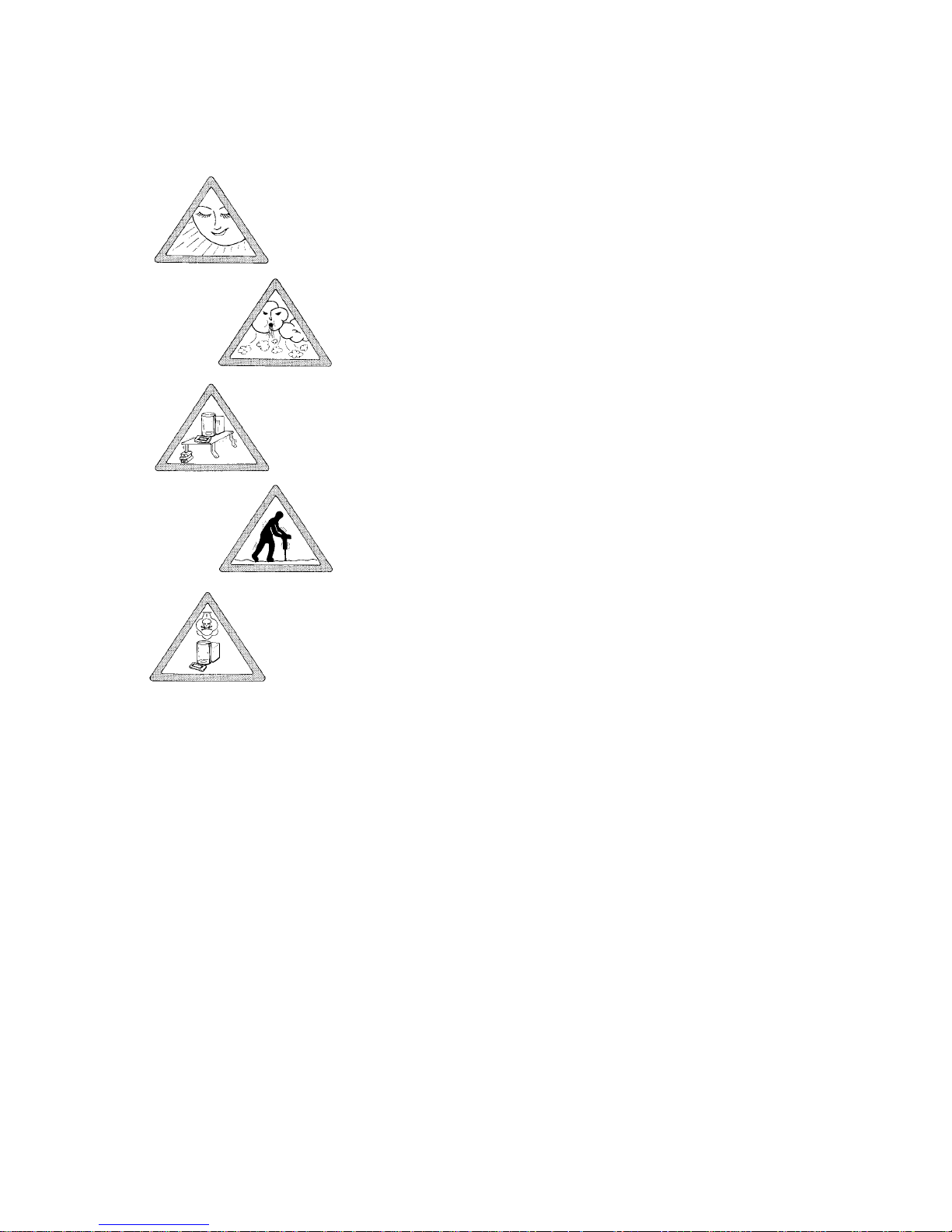
Ambient Conditions
Unfavourable ambient conditions may affect the weight readouts.
Therefore, choose a suitable place to set u p your balance. lt should not be exposed to the following:
—
Extreme heat radiation
—
Drafts
—
Extreme- vibrations
—
Aggressive chemical atmospheres
Set up your balance on a sturdy fable or on a wall console (see "Accessories" in
"Part l): Product Data Sheet").
Do not expose the balance to extreme moisture over long pe rio d s. Mo isture in the
air can condense on the surfaces of a cold balance whenever it is brought to a
substantially warmer place. lf you transfer the balance to a warmer area, make
sure to condition it for about 2 hours at room temperature, leaving it unplugged.
Afterwards, if you keep the balance connected to AC power, the continuous positive difference in temperature between the inside of the balance and the outside
will practically rule out the effects of moisture condensation.
You can adapt the balance to your specific requirements and to the ambient conditions simply by changing the code settings in the balance operating menu. For
more information, t urn to "Part III: Balance Operating Menu."
Page 9

8
Getting Started
Place the components listed below inside the weighing chamber one at a time in
the Order given:
- shield disk (8)
- weighing pan (7)
- protective ring (6)
- interior weighing chamber draft shield (depending on the balance model) (5)
Place the small draft shield cover (2) on top of the semi cylindrical interior draft
shield door (4).
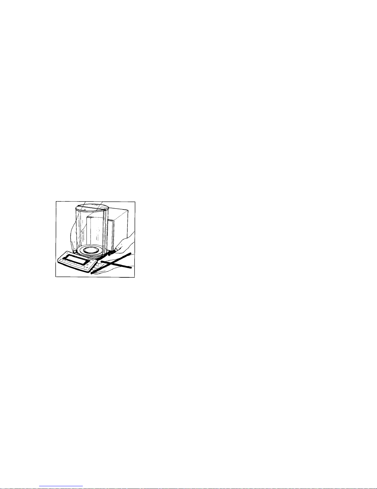
Adjusting the Exterior Draft Shield Element
The draft shield consists of two semi cylindrical dements, one of which functions as
a door. Turn the exterior draft shield element (3) by the riffled part on the bottom
to the position you desire, That way, you will have the opening located exactly
where it is most convenient for you. When adjusting the exterior element, be sure
to shield the weighing chamber from you r breath and the warmth of your hands
(see diagram on the left in addition).
Depending on your application, you can define the menu code so that the inferior
draft shield door (4) is opened by motor or by hand (see pp. 14).
Adjusting the Swivel-Mounted Display Unit
Move the swivel-mounted display unit (11) around the base of the draft shield to
adjust it to the position you desire (+/- 85°).
Page 10
9
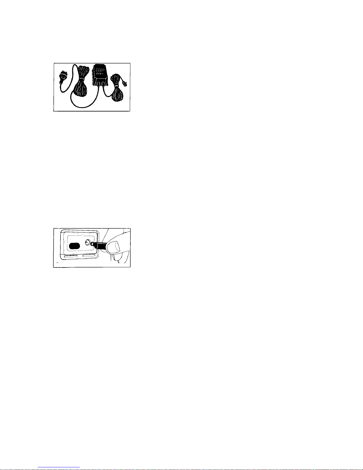
Connecting the Balance to Line Voltage
The balance is energized by a power supply. Make sure that the voltage rating
printed o n this unit is identical to your local line voltage .
lf the voltage specified on the label or the plug design of the power supply does
not match the rating or Standard you use, please contact your Sartorius Office or
dealer.
The power supply is suitable for installation as stationary equipment. To use a
main feeder cable from the ceiling or to mount a CEE plug, you will have to make
arrangements inside your facilities for installation of such cable equipment by a
certified electrician.
Important Note
Use only original Sartorius Power Supplies identified by the Sartorius label. Use of
power supplies from other manufacturers, even if these units have an approval
identification marking from a national testing laboratory, requires the consent of
an authorized Sartorius service technician.
To operate your balance using an external rechargeable battery, pack, see "Accessories" in "Part II: Product Data Sheet.".
Detailed information on additional options for powering the balance is available
in our Service Information bulletin, no. 15/88 (fore example, using local! extralow voltage).
Plug the cord of the power supply into the AC jack on the balance, Then insert the
plug of the power supply in a wall outlet.
Page 11
10
Safety Precautions
The power supply rated to Class 2 can be plugged into a wall outlet without taking any additional safety precautions. The pole of the Output voltage is connected
to the balance housing, which ca n b e grounded for Operation.
The interface (see "Interfacing Devices" on page 28 in addition) is also electrically
connected to the balance housing (ground).
Information on Rad io-Frequency Interfere nce:
Warning!
This equipment generates, uses and can radiate radio frequency energy and, if
not installed and used in accordance with the instruction manual, may cause interference to radio communications.
It has been tested and found to comply with the limits for a class A computing device pursuant to Subpart J of Part 15 of FCC rules, which are designed to provide
reasonable. protection against such interference, when operated in a commercial
environment Operation of this equipment in a residential area is likely to cause interference, in which case the user at this own expense will be required .to take
whatever measures may be required to correct the interference.
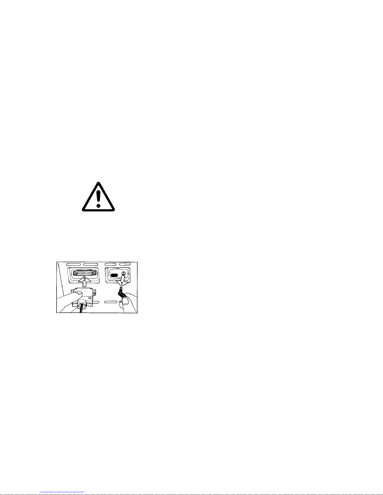
Connecting Electronic Devices (Peripherals)
Make sure to unplug the balance from the power
supply before you connect or disconnect a
peripheral device (printer or PC) to or from the
interface port. Safety Precautions
Page 12
11
Information on Weighing Electro statically Charged Samples
Problems with static electricity can occur in environments with low humidity. To
avoid these problems when you use your balance in such an area, wipe down the
entire draft shield on both the inside and outside with a commercially available
antistatic agent. In addition, the glass draft shield interior has a conductive coating.
There is a terminal (15) for connecting an equipote ntial g ro unding conductor to
the frame (housing) on the rear side of the balance. This is used for additionally
grounding a peripheral device connected to the balance (for example, a vibrating
spatula). The terminal is designed for single grounding wires up to .25" Standard
gauge or 6 mm
2
- and for .18" Standard gauge or 4 mm2 stranded wires.
lf you need to use electro statically charged glass or plastic Container s with a relatively large diamet er, you should utilize our antist a t ic pan (155 mm – see "Acce s sories" in "Part II: Product Data Sheet").
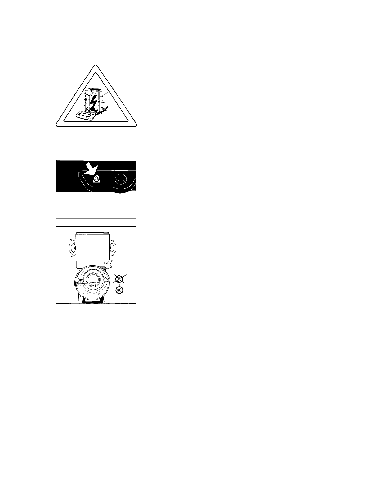
Levelling the Balance Using the Level Indicator
At the point of use, level the balance using the levelling feet (9) so t hat the air
bubble is centered within the circle of the level indicator (10).
To level the balance .using the level Indicator as a guide:
Extend the levelling feet (turn clockwise) to lift the balance.
Retract the feet (turn counter clockwise) to lower the balance.
Page 13

12
How to Operate the Balance
After initially connecting the balance to line power (or after a relatively
long power outage), allow for at least 2 hours' warmup.
Working with the Research Series Balance requires a smooth, uninterrupted technique.
The weight display shows the following special codes for your information:
OFF
The balance was disconnects from line power (power failure or outage; the balance was reconnected to line power).
0 (standby)
The display has been turned off by the
key (27), and the balance is now in the
ready-to-operate mode and does not require warmup.
(busy)
Once you turn on the balance, the
symbol is displayed until you press a key.
During Operation, this symbol indicates that the balance processor is still busy
processing s function and will not accept any other commands to perform functions at this time.
CAL
I
The balance has internal calibration weights and can be calibrated with the
key (for the "Quick-CAL” function, see also page 22).
, R1 or R2
The number in the R code identifies the particular weighing range you have selected.
Symbol for the application selected (in this case, the weighing mode and toggling
among the weighing ranges).
Page 14

13
Important Note
lf the
symbol flashes, this means that the balance wants to self-calibrate. You
do not need to interrupt your weighing procedure, because the balance will wait
until it detects that you have stopped weighing for one complete minute.
Afterwards, the balance will perform fully automatic infernal calibration. The
symbol will flash until the balance Starts this fully automatic procedure on its own
or until you activate one of the calibration functions by pressing a key (see p p.
22).
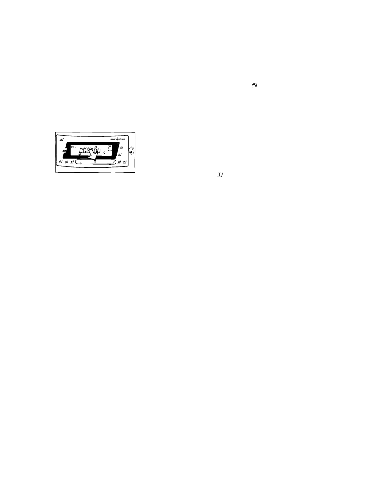
Turning the Display On and Off (Standby Mode)
Press the
key (27) to turn the display on or off.
Self-Test
After the balance has been turned on, an automatic self-test of the balance's electronic circuitry is performed, and the draft shield closes automatically.
It ends with a readout of "0.00000 g" or "0.0000 g" ( depending on your b a lance model or the display mode selected).
Important Note for Automatic Operation with a Robot
To be on the safe side for automatic Operation of the -balance with a robot, you
should turn off the full y a utomatic draft shield functi on (see "Part III: Balance Op erating Menu"). Otherwise, if a power outage occurs and the balance is automatically restarted, the robot arm may accidentally hit the draft shield as it is closing.
Page 15

14
Opening and Closing the Draft Shield Door
If you are loading small objects, open the draft shield
only as far as is absolutely necessary for your
application. This reduces the amount of draft so
your balance will stabilize faster than it normally
would when the draft shield is wide-open.
You have several options for operating the interior draft shield door (4):
– Semi-Automatic Mode (Aperture Angle s 170°) –
Press one of the keys labeled
(22) to have the draft shield door opened or
closed by motor.
The interior draft shield door moves slowly the first time it is opene d after connecting the balance to AC power.
– Semi-Automatic with an Aperture Angle of 10° to 140° –
By a "self-teaching function," the draft shield door can "learn" to open automatically to a user-define d aperture angle from 10° to 140°:
To define this angle, move the interior draft shield door (4) to the desire d Po sitio n.
Page 16

15
Press the
key (22] to have the draft shield door closed by motor.
While closing, the door moves slowly. The previously adjusted aperture angle is
stored in the process.
Now if you press the
key (22) again, the draft shield door will open at a faster
speed to the Position you selected.
You can load and remove a tare container with a diameter exceeding the aperture angle, without having to change the stored aperture setting. To do
so, press the
key (22) for approx. 2 seconds.
This will cause the draft shield door to open automatically as far as it will go
(170°).
You can always change the aperture angle by manually adjusting the position of
the draft shield door.
lf you want the draft shield door (4) to open completely (170° C) after you p re s s
the
key, just open the door manually as far as it will go.
Important Note
The aperture angle remains stored even after you have turned off the display u
sing the
key.
A stored aperture setting will not be erased until you unplug the balance from AC
current.
– Manual Mode –
Of course, you can also open and dose the draft shield door (4) by hand.
Page 17
16
Weighing
Place your sample on the weighing pan (7) to determine the weight, and dose the
draft shield door (for example, by pressing the
key (22). Do not read off the
weight indicated in the display (18) until the weight unit (in this case “g” or a different unit selected - see "Part III: Balance Operating Menu"} appears as the stability symbol.
Taring
lf you wish to use a Container or if the weight display does not indicate
0.00000 g or 0.0000 g (depe n d i ng on the particular bal a n ce model you are us ing, or on the display mode selected), zero the display before You weigh.
To do so, press the tare control
(24).
During taring, you can have the fully automatic draft shield function either on or
off. To shorten work procedures; and make them easier, you should have this fully
automatic function o n active Status. In this case, after you press the tare control,
the draft shield door will dose, the balance will be tared, and the draft shield door
will re-open.
For more information on turning this function on or off b y menu code, refer to
"Part III: Balance Operating Menu."
Page 18

1
7
Weighing Range Structure
SuperRange - "SingleWide-Range Balance"
(identified by S in the model designation RC...S)
SuperRange models have an extraordinarily high resolution, i.e., the weighing
range has a resolution ranging u p to a few million digits. There is one level of
fine readability for the entire weighing range [for example: 0.01 mg).
DualRange
(identified by D in the model designation RC...D)
2 weighing ranges;
a fine range and a Standard range
The balance automatically)' switches from the fine range which is 10 times more
accurate (for example:
52 g capacity - readability of 0.01 mg) to the Standard range (for Instance:
210 g capacity -01 mg readability} when the balance is loaded beyond the fine
range limit (>52 g). The weight readout is displayed with the readabil ity o f the
Standard range until you tare in the fine range (loa d <52 g).
PolyRange
(identified by P in the model designation RC...P).
-Wide weighing range with multiple levels of accuracy
In the PolyRange balance, the weighing range is divided into as many as 3
ranges, each with a different readability. In the various ranges, the readability
will adjust so that the last numeral of a 'weight readout is displayed with a resolution of 1, 2 or 5 digits.
After you press the tare control (24), you will obtain the highest possible resolution, even when the balance is loaded.
Page 19
18
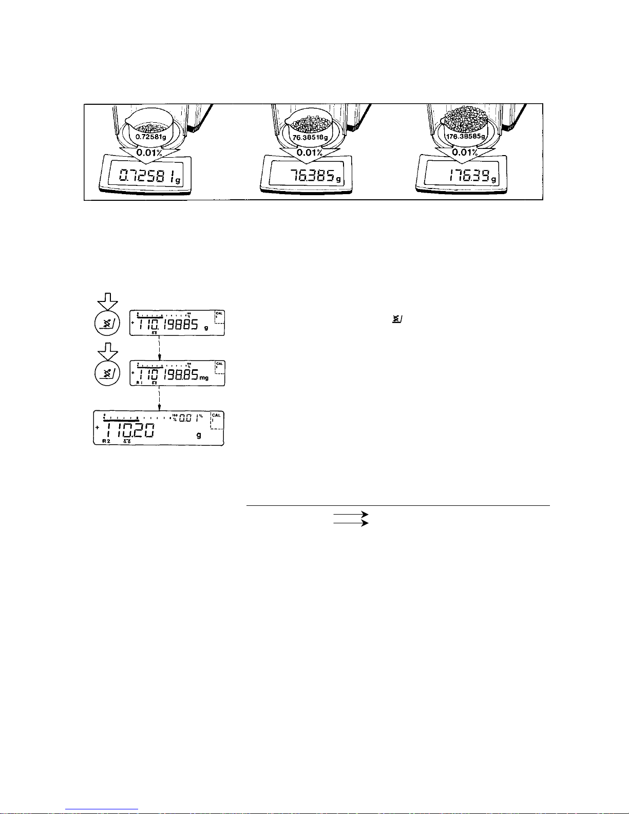
Weighing in the IQ-Mode™
(Load-Dependent Readability)
In the IQ-Mode™ (IQ = Intelligently quick), weighing is done with a loaddependent readability of 0.01 % (for different settings, see "Part III: Bal a nce Operating Menu') throughout the entire weighing range of the balance. The display
resolution of the l a st digit changes in increments of 1, 2, 5, 10, 20, etc. in proportion 1o the weight of a sample.
Oftentimes, a display accuracy of 10 milligrams is sufficient for a load of approx.
110 g. In this case. it makes s ense to select weighing range R 1 with an accuracy
of 0.01 o/a by pressing the toggle key
(25).
While you are filling u p to a target weight. it is certainly easier to work with a
target of 110.20 g than with an absolutely accurate readout of 110.1S885 g.
By selecting the IQ-Mode™ for automatic adaption of the display accuracy, you
will obtain stable weight readouts even faster.
In daily laboratory routines, analyses must often be performed with a certain accuracy. The IQ-Mode™ meets this requirement - on a semi-microbalance, it gives
you the full accuracy of all 5 decimal places for initial sample weights below 1 g;
whereas for heavier samples (of 100 g o r more), it provides lower readability
which is sufficient:
Initial sample weight readout
Below 1 g
Above 100 g
0,98756 g
123,13 g
Page 20
19
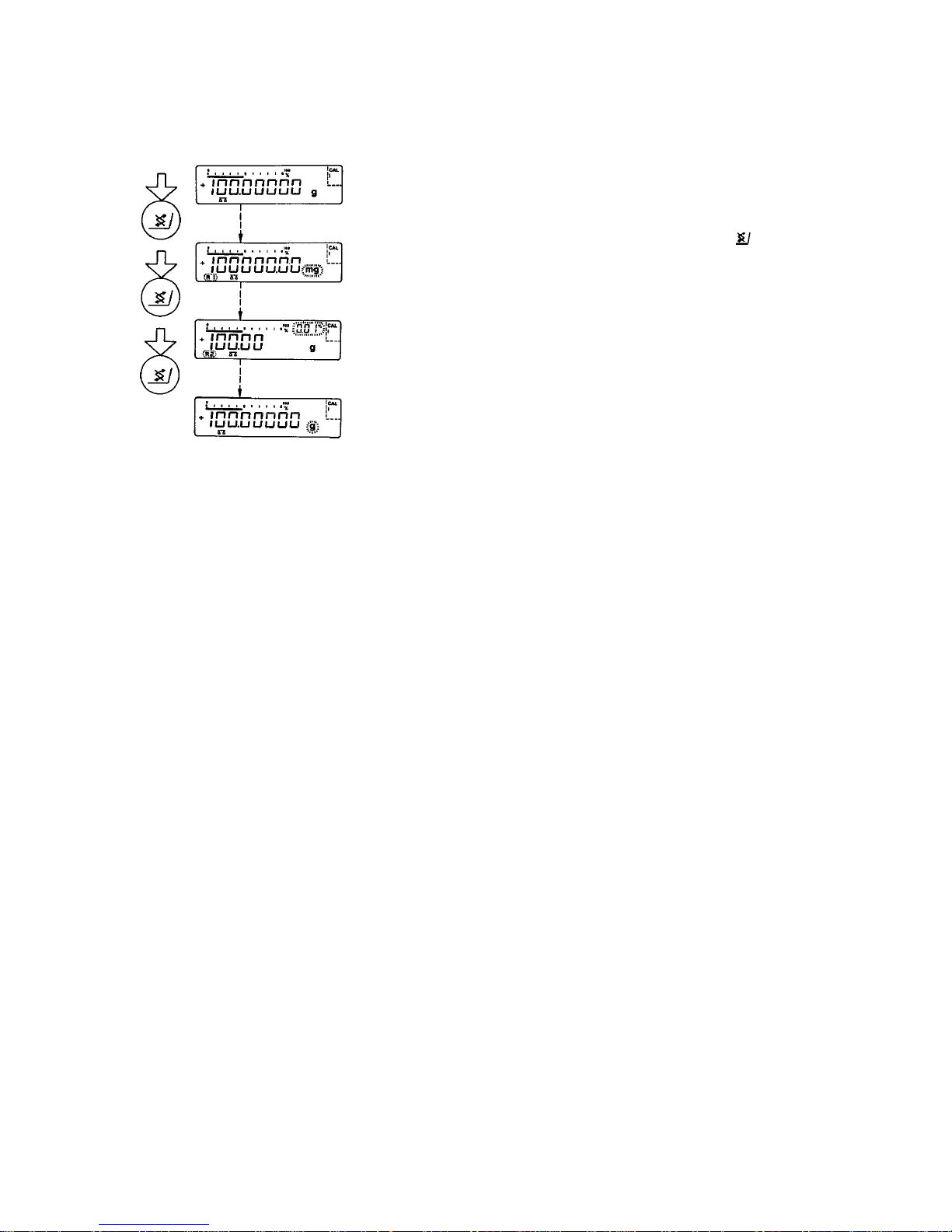
Mass Unit Conversion by Toggling
You can have the weight displayed in grams or milligrams.
To select the three weighing ranges one after the other, press the
toggle key
(25] each time.
In addition to grams and milligrams, this balance gives you a wide variety of
other menu-definable international weight unit options. For more information, refer to "Part III: Balance Operating Menu."
Page 21

20
Calibration and Linearization
During calibration, the balance is adapted to changes in ambient conditions.
You should recalibrate your balance each lime you set it up in a different area or
when the ambient conditions change (fore example, temperature or barometric
pressure). When these conditions are constant, the balance should be calibrated
once a day. To meet the highest requirements for accurate weighing, we recommend that you calibrate the balance before each weighing series.
Make sure that the draft shield is closed before calibration or linearization Starts.
You can abort any calibration or linearization procedure by pressing the
key (28),
The balance offers you various calibration and linearization functions. The function you select is indicated in the display by one of the following special codes;
»CALI« The balance has built-in calibration weights and can be calibrated
with the
key (“Quick-CAL" - see page 22)
»CALI« The calibration or linearization function is activated
»C.I.« Internal calibration
»C.t.« Calibration test
»L.I.« Linearisieren intern
»C.E.« Eternal calibration
Page 22

21
Fully Automatic Calibration
lf the
symbol flashes, this means that the balance wants to self--calibrate. You
do not need 1o interrupt your weighing procedure, because the balance will wait
until it detects that you have stopped weighing for one complete minute.
Afterwards, the balance will perform fully automatic internal calibration.
During this procedure, the draft shield should be closed 1o ensure that calibration
is done correctly.
The symbol will flash until the balance Starts this fully automatic procedure on its
own o r until you activate one of the calibration functions by pressing a key (sees
next page).
The balance can perform fully automatic internal calibration two hour after it has
been connected to line power or once the temperature has changed by ±1.5 degrees since the last calibration process. Independently of these factors, the balance can perform a fully automatic calibration after four hours at the latest.
To turn off the fully automatic calibration function by menu code, refer to "Part III:
Balance Operating Menu."
In the fully automatic mode, the draft shield closes after
or the tare control is
pressed.
Page 23
22
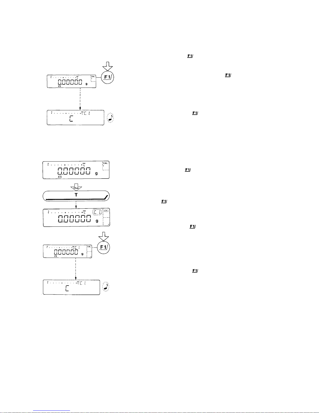
INTERNAL CALIBRATION
Quick-CAL Function using the
key:
Unload the pan, close the draft shield and tare.
When the balance displays a zero readout, press the
key (20).
"C" will now be displayed. The built-in calibration weights are internal~ applied
by servomotor and removed at the end of calibration.
lf external interference affects the calibration procedure, you may obtain a brief
display of the e rror message "Err 02. "
In this case, tare and then press the
key again when a zero readout appears.
An acoustic Signal indicates the end of calibration.
Internal Calibration Using the Tare Control:
Calibrate the balance using the tare control if an application program (such as the
tare memory) is assigned to the
key by menu code in the balance operating
menu (see Parts III a nd IV).
Press the tare control (24) for at least 2 seconds until "C.l." and "CAL” are displayed (next to the
key).
Unload the pan, make sure the draft shield is closed, and tare. When the balance
displays a zero readout, press the
key (20).
“C" will now be displayed. The built-in calibration weights are internal by applied
by servomotor and removed at the end of calibration.
If external interference affects the calibration procedure, you may obtain a brief
display of the e rror message "Err 02. "
In this case, tare and then press the
key again when a zero readout appears.
An acoustic signal indicates the end of calibration.
Page 24
23
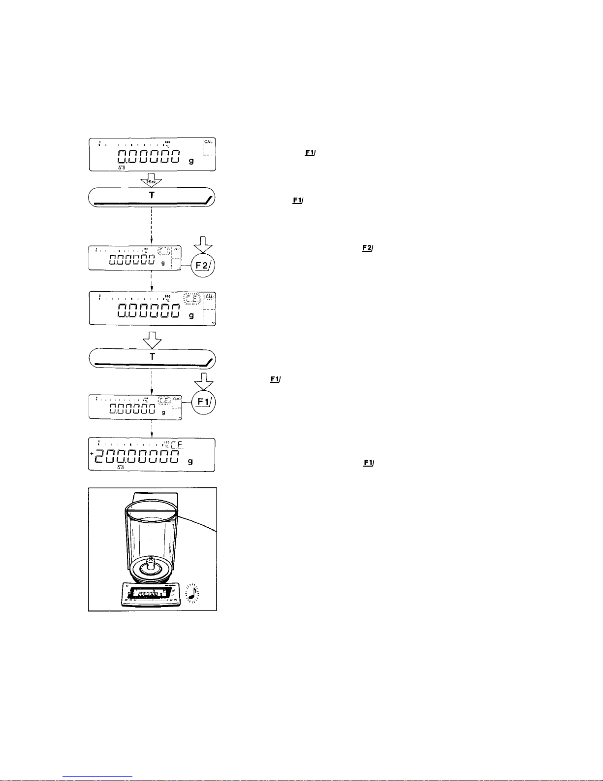
EXTERNAL CALIBRATION
Use only calibration weights that have tolerances equal or better than those of accuracy class E2 (for 200 g -> ±0. 3 mg).
Press the tare control (24) for a1 least 2 seconds until "C.l." and “CAL” are displayed (next to the
key).
Important Note
lf you press the
key (20) when "C.l." is displayed, this will activate the internal
calibration function.
For "external calibration" press the
key (21) until "C.E." is displayed.
“C.E.” Stands for "external calibration."
Unload the balance, make sure the draft shield is closed, and tare.
Press the
key (20) when a zero readout is displayed. Afterwards, the calibra-
tion weight readout will be indicated.
lf external interference affects the calibration procedure, you may obtain a brief
display of the e rror message "Err 02. "
In this case, tare and then press the
key again when a zero readout appears.
Center the calibration weight on the weighing pan and dose the draft shield door.
An acoustic Signal indicates the end of calibration.
Page 25

24
CALIBRATION TEST
Rather substantial changes In barometric pressure and temperature may affect t
he display response of these highly accurate Research Series balances.
To ensure that you obtain the full accuracy of these balances, even when you use
the entire weighing range, we have implemented a calibra tion lest function. It will
help you decide whether o r not you need to recalibrate your balance (for example, to maintain the same accuracy during long-term weighing series).
Press the tare control (24) for at least 2 seconds until "C.l." and "CAL" are displayed (next to the
key).
Select the calibration test by pressing the
key (21) twice until "C.t." is dis-
played.
Unload the balance, make sure the draft shield is closed and tare.
"C.t." Stands for “calibration fest.”
When the balance displays a zero readout, press the
key (20). The built-in
calibration weights are now internal by applied by servomotor.
Afterwards, the deviation of the momentary weight readout from the target weight
(displayed in grams only) is indicated.
lf external interference affects the calibration test procedure, you may obtain a
brief display of the error message " E R R 02."
In this case, tare and then press the
key again when a zero readout appears.
Important Note
The balance should be recalibrated if the deviation of the readout from zero exceeds the tolerance of the calibration weights used (accuracy class E2 ± 0.3mg).
-key (20): The balance automatically calibrated
(see also page 21).)
or
-key (21): Quits the calibration test
An acoustic Signal indicates the end of the calibration test.
Page 26

25
INTERNAL LINEARIZATION
Press the tare control {24) for at least 2 seconds until "C.l." and “CAL” are displayed (next to the
key).
Select "internal linearization" by p re s s ing the
key (21} three times until "L.l."
is displayed.
Unload the balance, make sure the draft shield is closed and tare.
"L.l." Stands for "internal linearization."
When a zero readout is displayed, press the
key (20). “C” will now be indicated. The built-in weights are internally applied one after the other by the Servomotor, and the weighing range is automatically liberalized.
lf external interference affects the linearization procedure, you may obtain a brief
display of the e rror message "Err 02. "
In this case, tare and then press the
key again when a zero readout appears.
An acoustic signal indicates the end of linearization.
Important Note
The balance automatically self-calibrates after each internal linearization procedure.
Page 27

26
Data Interface
lf you wish to record weight data using a Sartorius Data Printer or process them
using "Data Control," plug the printer connector into the interface port (14} of the
balance. You do not need to adjust any settings!
Remove the protective cap from the data interface port.
Caution!
Make sure to unplug the balance from the power supply before you connect or
disconnect a peripheral device (printer or PC) to or from the interface port.
To print data on hard copy or Output them on the
screen o1 an on-line Computer, press the
key (23).
For information o n s pecial data output Parameters, se-e "Utilities" under "Pa rt III:
Balance Operating Menu."
During data Output, you can have the fully automatic draft shield function either
on or off.
To shorten work procedures and make them easier, you should have this fully
automatic function on active Status. In this case, after you press
key, the draft
shield door will dose, the balance will output data, and the draft shield door will
re-open.
For more information on turning this fully automatic draft shield function on or off
by menu code, refe r t o "Part III: Balance Opera ting Menu."
Page 28

2
7
Interfacing Devices with the Balance
Please note that the interface port is electrically connected lo the protective
grounding conductor of the balance housing. The interface cables supplied as
Standard equipment are shielded, and both ends of each cable are electrically
connected to the connector cases. This co nnection may result in interference
caused by ground loops o r by transient currents if you have grounded the hous ing or connected the protective grounding conductor for line power. If necessary
connect an equipotent bonding conductor to the balance
Page 29

28
Below-Balance Weighing
A port for a below-balance weighing hanger is available on the bottom of the
balance.
To fasten the hanger, open the below-balan c e por t by r emov i ng t h e tw o scr ews on
the bottom of the balance and detaching the closing plate.
Now you can attach a sample using a Suspension wire, for example.
Common applications for below-balance weighing include specific gravity determination or immersing a sample in a special atmosphere (medium for reaction).
You can also use the M2 thread to attach a sample.
Important Note
When you use such below-balance weighing hangers, you must install a shield to
eliminate drafts..
How to Fasten the Antitheft Locking Device
To fasten the antitheft locking device, use the lug (16) located on the rear panel of
the balance.
At the place of installation, secure your balance with the lock.
Page 30
29
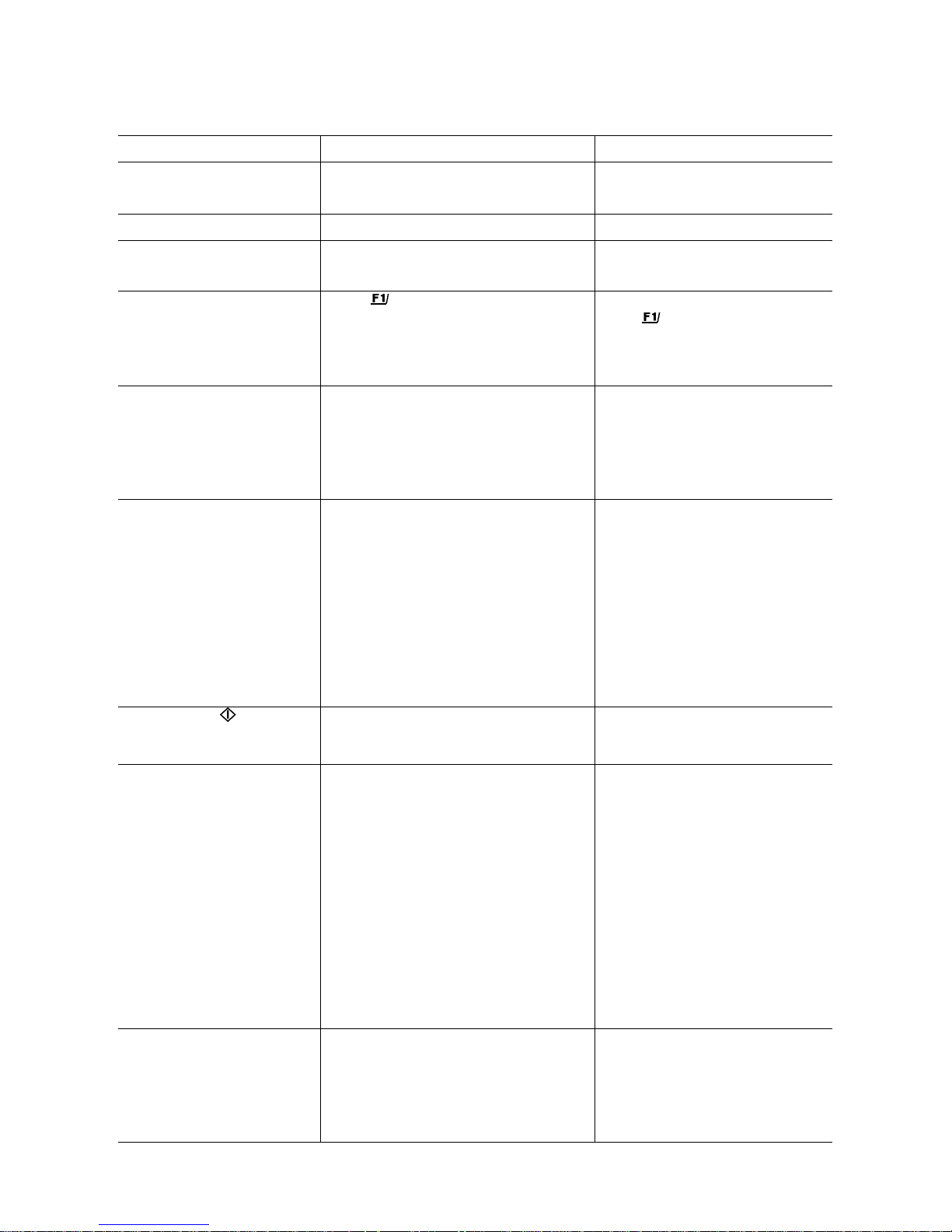
Troubleshooting Guide
Problem … Causes … Solution
No segments appear in the weight
display (19)
—
No line power available
—
The power supply is not plugged in
—
Check power supply
—
Plug in the power supply
The display shows “Err 54” or ”L”
—
The weighing pan (7) is not in place
—
Position the pan
The display shows ”H”
—
The load exceeds the capacity of the
balance
—
Unload the balance
The display (19) briefly shows
”Err 02”
—
The key (20) was not pressed when the
display indicated a zero readout during
calibration
—
The balance is loaded
—
Press the tare control and re-press
the
key
—
Unload the balance
The display (19) briefly shows
”Err 03” or ”Err 04”
—
The balance is in the warmup phase
—
The weighing System is affected by drafts
or vibrations
—
After plugging the balance into line
power, allow for at least 2 hours'
warmup
—
Set up the balance in another area
The special code “C” does not go
out in the weight display
—
The balance is not ready to calibrate or is
in the warmup phase
—
The weighing system is affected by drafts or
vibrations
—
The draft shield door is not closed
—
The port for the below-balance weighing
hanger is open
—
After plugging in the balance using
the power supply, allow for at least 2
hours' warmup
—
Access the menu to select the correct
code for the weighing enviro nment
(see Part III)
—
Check draft shield function and dose
door
Fasten the closing plate to dose the port
for below balance weighing
The special code does not go
out in the weight display (19)
—
None of the keys has been pressed after the
balance was turned on
—
Press a key
The weight readout changes
constantly
—
Unstable ambient conditions
—
Too much Vibration or the balance is
exposed to a draft
—
The door of the draft shield is not
completely closed
—
A draft shield cover is not in place
—
A foreign object is caught between the pan
and the bottom of the weighing chamber
—
The port for the below-balance weighing
hanger is open
—
The sample does not have a stable weight
(absorbs moisture or evaporates)
—
Set up the balance in another area
—
Access the menu to select the correct
code for the weighing enviro nment
(see Part III)
—
Close the draft shield door
—
Position the draft shield cover
—
Remove foreign object
—
Fasten the plate to dose the port for
below-balance weighing
The weight readout is obviously
wrong
—
The balance is not calibrated
—
The balance was not tared
before weighing
—
The air bubble in the level indicator (10) is
not within the circle
—
Calibrate (see pp. 20-25)
—
Tare before weighing
—
Level the balance (see page 11)
Page 31

30
Care and Maintenance
Before cleaning the balance, unplug the power supply from the wall outlet.
Cleaning the Balance Housing and the Draft Shield
Please do not use any aggressive cleaning agents (solvents or similar agents]. Instead, use a piece of lint-free cloth which has been wet with a mild detergent.
Clean the semi cylindrical elements of the draft shield with a commercially available glass cleaning agent.
Make sure that no liquid enters the balance housing.
After cleaning, wipe down the balance with a soft, dry piece of cloth.
Cleaning the Weighing Chamber
Keep the draft shield base plate from becoming too dirty:
Carefully remove spilled powder from the weighing chamber by using a small
vacuum cleaner (such as a small car vacuum cleaner with a mini-hose attached).
Afterwards, remove the weighing pan (7] and the shield disk (8) from the weighing chamber.
Vacuum out the remaining powder from the weighing chamber using the same
equipment described above.
Do not clean the weighing chamber by blowing off powder from the parts!
To remove liquid spills, use blotting paper.
Page 32

31
Safety Inspection
lf there is any indication that safe Operation of the balance is no longer warranted. turn off the power and unplug the balance from the power supply immediately. Lock the balance and the power supply in a secure place lo ensure that
they cannot be used for the time being.
Safe Operation of the equipment is no longer ensured when
—
there is visible damage 1o the power supply
—
the power supply no Ionger functions properly
—
the power supply has been stored for relatively Ion g periods under unfavourable conditions
In this case, notify your nearest Sartorius Service Center or the International Service Support Department based in Goettingen, Germany. Only service technicians
who have access to the required maintenance manuals are allowed to perform
maintenance and repair work on the equipment.
We recommend that the balance together with the power supply be inspected by
a qualified Sartorius service technician according to the following checklist;
—
Insulation resistance >7 megohms measured with a constant voltage of at
least 500 V at a 500 kohm l oad
—
Equivalent leakage current <0.05 mA measured by a property calibrated
multimeter
The duration and number of measurements should be determined by a qualified
Sartorius service technician according to the particular ambient and operational!
conditions for the power supply.
Such inspection should be done at least once a year.
Page 33

32
Safety Certificate
The electrical and electronic components used in the balance are rated to at least
Class KSF according to DIN 40040.
Pursuant to the German Directive for the Implementation of Regulations fo
r
Prevention of Accidents "Elektrische Anlagen und Betriebsmittel (VBG 4)"
(Electrical Installations and Equipment] of April 1986, in conjunction with
Article 10 of the Low-Voltage Directive 73/23/EEC issued on February IS,
1973, by the European Comm unity it is hereby certified hat the equipment
delivered, "Electronic Semi-Microbalance or Analytical Balance of the RC
Series," is manufactured and tested in compliance with the following
DIN/VDE regulations:
DIN IEC 348/VDE 0411
Safety requirements for electronic measuring apparatus
DIN IEC 380/VDE 0806
Safety of electrically energized office machines
DIN IEC 601/VDE 0750
Safety of medical electrical equipment
When you use electrical equipment in installations and under ambient
conditions requiring higher safety Standards, you must comply with the
provisions as specified in the applicable regulations for Installation in your
country.
Page 34

Page 35

Sartorius AG
B 37070 Göttingen
P Weender Landstraße 94–108, 37075 Göttingen
T (0551) 308-0, F (0551) 308-3289
Internet: http://www.sartorius.com
Copyright by Sartorius AG, Göttingen, Deutschland.
All rights reserved. No part of this publication may be
printed or translated in any form or by any means without
the prior written permission of Sartorius AG.
Sartorius AG reserves the right to make change to the
technology, features, specification and design of the equipment
without notice.
Page 36

Sartorius
Research Series
Product Data Sheet
WRC 6002-e93042
Page 37

Dimensions (Scale Drawings)
2
Page 38

Specifications
Model RC 210S RC 210P RC 210D RC 250S
Weighing range structure SuperRange PolyRange DualRange SuperRange
Capacity/weighing range levels g 210 60 / 110 / 210 52 / 210 250
Readability mg 0.01 0.01 / 0.02 / 0.05 0.01 / 0.1 0.1
Tare range (by subtraction) g -210 -210 -210 -250
Reproducibility (standard deviation)*
for weighing range
mg
g
≤
±0.015 ±0.02 ±0.03
0-50 50-100 100-210
≤
±0.02 /0.04/0.05
≤
±0.02 /0.1
≤
±0.1
Linearity mg
≤
±0.12
≤
±0.15
≤
±0.03/0.2
≤
±0.2
Linearity within 5 g mg ≤ ±0.02
≤
±0.02
≤
±0.02
Response time (typical) s
≤
10
≤
10
≤
10
≤
2.5
Response time in the IQ-Mode (0.01 %) s 2.5 2.5 2.5 1.5
Adaption to ambient conditions and application requirements 4 optimized filter levels
Display update (depends on the filter level selected) s 0.2 – 0.4 (selectable)
Allowable ambient temperature range for operation
o
C +5 … +40
Operating temperature range
o
C +10 … +30
Sensitivity drift within + 10 … + 30o C /oC
≤
±1 ·
10-6
Moisture-proof rating acc. to D IN 40040 Class F, non-condensing
Pan size mm Ø 90 / 3.5”
Weighing chamber (Ø x H), approx. mm 166 x 248/ 6.5 x 9.8”
Net weight, approx. kg 12 26.4 lbs
AC power source/power requirements V~ power supply. 230 or 115. +15 % . . . –20 %
Frequency Hz 48 – 60
Power consumption incl. power supply, approx. VA max.: 28; average: 16
Selectable weight units g, kg, ct, lb, oz, ozt, tlh, tls, tlt, gr, dwt and mg
Applications programs
mass unit conversion, tare memory, net total, weighing in percent,
over/under checkweighing (classification and filling), counting
Automatic zero tracking function (can be turned off by menu code) standard feature
Built-in interface
RS 232 C-S/V24-V28, RS 423/V10; 7-bit; parity;: even, mark, odd, spa c e;
transmission rates: 150 … 19,200 baud; 1 or 2 stop bits; software/hardware handshake
Standard features/equipment supplied
Dust cover x x x x
Power supply x x x x
Attachment for below-balance weighing x x x x
Interior weighing chamber draft shield x x x x
Built-in automatic calibration available on request
*
= standard deviation of the reproducibilit y according to DIN 1319, Part 3
3
Page 39

Accessories (Options)
Data Printer YDP02-0DV1
with date/time
and statistics functions
Print speed
approx. lines/sec. 1.5
Printer housing (WxDxH)
in mm 150x138x43
in inches 5.9x5.4x1.7
Data Control terminal 73822 C &
with built-in printer, LCD and
set of programs
Replace & with one
of the codes below:
2086 for statistics
2126 for specific gravity/density
External rechargeable
batterypack YRB02Z
hours of Operation: approx. 10;
rechargeable by power supply
(detailed information on additional
options for powering the balance
is available in our Service
Information bulletin 15/88)
BalanceReaderSof tw a re YAK 10 PC-0002
for collecting data that are transmitted by your
Sartorius Balance to a commercially available
personal Computer. These data are read into
spreadsheets and stored. The stored spreadsheets
can be further processed using commercially
available Standard Software (Excel, Lotus 1-2-3,
etc.). This applications kit includes the following
Software and equipment:
– - 3
1/2
" and 5
1/4
program diskettes
– program description
– interface cable
– adapter (25-pin to 9-pin)
4
Page 40

Density determination kit YDK 01
Draft shield cover
with pipette opening YDS 01 RC
Antistatic pan YWP 01
Weighing bowls
Stainless steel bowl, 20 g 6003
Glass bowl , 20 g 6015
Stainless steel bowl
with pouring spout, 300 ml 6407
Foot switch with T-connector
and three functions YPE 01 RC
for opening/closing the draft shield,
taring and printing
Universal remote - control switch
with menu-code definable print,
tare, F1/F2 key or open/close
draft shield function
Foot switch 7223
Foot switch with T-connector YPE 01 Z
Hand switch 7226
T-connector 7258
Antivibration balance fable YWT 01
Wall console 6804
Vibrating spatula 6025
Forceps 6708-62
Dust brush 6708-02
Carrying case YDB01RC
Dust cover 6960RC01
5
Page 41

Sartorius AG
B 37070 Göttingen
P Weender Landstraße 94–108, 37075 Göttingen
T (0551) 308-0, F (0551) 308-3289
Internet: http://www.sartorius.com
Copyright by Sartorius AG, Göttingen, Deutschland.
All rights reserved. No part of this publication may be
printed or translated in any form or by any means without
the prior written permission of Sartorius AG.
Sartorius AG reserves the right to make change to the
technology, features, specification and design of the equipment
without notice.
Page 42

Sartorius
Research Series
Balance Operating Menu
WRC 6003-e93042
Page 43

2
Overview of the Balance Operating Menu
Page
How to Access the Menu 3
Examples for Changing Menu Code Settings 6
How to Undo All Menu Code Changes: Reset Function 9
Balance Operating Parameters 11
How to Adapt the Balance to Ambient Conditions 11
Standard Weighing Mode - Manual Filling Mode 11
Stability Range 11
Stability Symbol Delay 12
Tare Parameter 12
Auto Zero Function 12
Weighing in Three Range s 13
How to Select the Number of Ranges 13
Weight Units 13
IQ-Mode™ 15
Display Modes 16
Final Readout Mode "- -" 16
Last Numeral Blanked When the Load Changes 16
Display Accuracy 16
PolyRange Function 16
Calibration and Linearization Functions 17
Utilities for Printouts or Data Transfer 20
Data l D Codes 21
Additional Functions 22
Menu Access Function 22
Beep Tone (Acoustic Signal) 22
Blocking the Keys 22
Analog Display: Bar Graph/Marker 23
Power-On Mode 23
Display Backlighting 23
Fully Automatic Draft Shield Function 24
Display Accuracy with the Draft Shield Automatically Opened or Manually Adjusted 24
IQ-Mode™ with the Draft Shield Automatically Opened or Manually Adjusted 25
GLP/GMP Printout or Reco rd 26
Setting the ID No./Time/Date 31
Reset Function 32
Brief Instructions fo r Setting a Menu Code 33
Quick-Reference Guide to All Menu Code Settings 34
Page 44

3
How to Access the Menu
The Sartorius MC1 Balance can do much more than "just weigh."
It can "think" in various units of measure, adapt to unfavourable conditions and process weight data for a variety of
applications.
In the operating menu, you can define how your balance will adapt to ambient conditions and also how it will work to meet
your special requirements.
For your convenience, the m enu codes have been factory-set so that you do not have to make any changes if yo u want to "just
weigh," and if your balance will be operated under normal ambient conditions.
To select specific functions, you will need to set the respective menu code.
This code tells the microcomputer inside the balance what it has to do to meet your requirements.
Here is a short example to help you understand how to set a menu code.
Just take a look at the picture below.
See the apple on one of the trees?
Now if you want to explain to somebody where this apple is located, you could number the trees, the main branches and the
small branches according to a certain pattern.
Then you could describe the location like this: the apple is on tree no. 3, main branch no. 1 and small branch no. 4. To express
this as a menu code, you'd say: 3 1 4.
Now that’s easy enough, isn't it?
Page 45

4
The areas where certain code settings are found in the balance/scale operating menu are designated similarly to the way in
which the location of the apple is pinpointed.
Going back to our example, tree no. 3:
The apple is located exactly where the unit symbol "ct" is on our menu "tree."
On main branch no. 1, you'll f ind all weight units for the seco nd weighing range which you select with the toggle key
. On
small branch no..4, carats - "ct" is defined
as the weight unit - so your code will be 3 1 4.
The weight unit "g" for grams is on the same tree (3) and the same main branch (1 ), but on small branch no. 2.
Therefore, the code for grams is 3 1 2.
The code for pounds (lb) is 3 1 5, and so on.
(For a list of codes, see "Overview of the Weight Units," column for the "2nd range," on page 14.)
At this point, you'll probably want to know how to change the menu codes stored in your balance.
Go right ahead and try to change a few of the menu code settings. That’s the best way to familiarize yourself with the
performance capabilities and the versatility of the microcomputer in your Sartorius Balance.
Don't worry!
Even if you've selected the "wildest" codes and totally thrown off all the code settings you need, all you have to do is press a
key to set things straight again.
Your balance will work just like it did when it left the factory - with the original factory-set menu codes.
There are three Steps to changing a code:
- access the menu
- set a code
- confirm and store this code
To set a code, use the four keys which are defined on the display as arrow points to indicate the direction.
Function Key
Go back
Go forward
increase
Decrease
Page 46

5
Now for a little hands-on practice!
It's your turn to try a setting - how abo ut cha ng ing the weight unit in the second weighing ra nge (use
to select this range)
from grams to carats (et), Code: 3 1 4. (In our example, the 1
st
weighing range " " will remain unchanged.)
The balance operating menu is protected against accidental changes. That’s why you'll need to "unlock" it:
Change from the Status readout
to
-L- Stands for "list" for checking menu code settings, and
-C- Stands for "change" for selecting a different menu code.
In the following directions, we've included diagrams to show you what you actually see on the display and which key you need
to press, for example:
The text next to the diagrams tells you how to carry out each Step
Page 47

6
Examples for Changing Menu Code Settings
How to set code 3 1 4 for "ct" in the second weighing range
- Turn off the balance
- Turn it back on
- While all segments are displayed, briefly press the tare control
- If -L- is displayed, unlock the menu access switch
- Remove the protective cap located to the left of the AC jack o n the re ar pane l
of the balance, and move the switch in the direction of the arrow
- Change the left-hand number to “3”
- Move to the middle number
- Now move from "1" to the right-hand number (Whe n yo u m o ve to the right-
hand number, the previously set numeric code will appear.)
- Change the right-hand numbe r to “4”
- Confirm the code setting
Important Note:
You must press the tare control
in order to .confirm the code you have just set:
This is indicated by the "o" after the code.
- Press
to store your menu code setting
Page 48

7
That’s all there is to it!
Now, if you press the
key, you can read the weight in carats "ct":
Of course, you'll be in the IQ-Mode™, with a load-dependent readability of
0.01%, as defined by the factory-set menu code.
You say you don't like it?
You'd rather weigh in the unit "ct" with the highest possible accuracy down to the
last digit?
No problem!
Just set the appropriate code:
3 2 1. (You'll find this code listed under "Display Modes" on page 16.)
How to set code 3 2 1 for full resolution in the second weighing range
- Turn off the balance
- Turn it back on
- While all segments are displayed, briefly press the tare control
- Change the left-hand number to “3”
- Move to the middle number
- Change the middle number to “2”
- Move from "2" to the rig ht-ha nd number (When you move to the rig ht-ha nd
number, the previously set numeric code will appear.)
- Change the right-hand numbe r to “1”
Page 49

8
- Confirm the code setting
Important Note:
You must press the tare control
in order to .confirm the code you have just set:
This is indicated by the "o" after the code.
- Press
to store your menu code setting
Now you can read the weight in "ct" accurately down to the last digit.
Congratulations! You've just finished the two examples we've given to help familiarize you with how to use the code setting function.
Remember, the keys labelled
, , , , and have special functions
in this mode:
and = Move to the le ft and right, re spe ctive ly
and = Respectively increase and decrease a number by one
= Confirms a code setting
= Stores a code setting and leaves the menu
n the application programs, the
and keys will have other f unctio ns deter-
mined by the program that you have selected.
The particular function assigned is always shown on the display next to each key
for easy identification.
Before you begin to look for different menu codes in the description of the application programs, you should try out the reset function to undo all changes in order
to see how it works.
Page 50

9
How to Undo All Menu Code Changes - Reset Function
The reset function lets you undo all menu code changes, which means that you will obtain the original factory-set menu codes
so that your balance will operate according
to them. To use this function, you will need to select code 9 - - 1.
How to set code: 9 – – 1
- Turn off the balance
- Turn it back on
- While all segments are displayed, briefly press the tare control (
)
- Change the left-hand number to “9”
- Move to the middle number
For this code, the middle number is skipped.
Instead, you will always obtain the right-hand number.
- Change the number to “1”
- Confirm the code setting
Important Note:
You must press the tare control (
)to confirm the code you have just set:
This is indicated by the "o" after the code.
- Press “
” to store your menu code setting
All menu code settings are now the ones which were originally set at the factory.
Page 51

10
Note:
The actual menu code setting in the balance operating menu is identified by a small "o" after the last number. When you
access the operating menu, the previously set numeric code will be displayed after you select the left and the middle numbers,
which means the entire menu code setting is displayed. This makes it easy for you to check the m e nu code se ttings.
Please do not forget to relock the balance operating menu. The "-L-" indicates that it is currently locked:
You can lock the menu anytime you wish once you have accessed it. However, it is best if you wait until you have changed the
last code setting.
To use the locking function, make sure code 8 1 2 is set in the balance operating menu.
If code 8 1 1 is set, the menu access switch will not l ock.
In this case, "-C-" will be displayed whenever you access the menu:
The lists on the next pages give just a small sampling of the code options available for the balance operating menu. These
options involve Standard balance Operation, utilities for printouts or data transfer, and additional functions.
lf you would like to change several menu code settings, you do not have to press
/ after each change to leave the balance
operating menu.
For your convenience, we've indicated all factory code settings with an "*."
You'll find information on the application programs in "Part IV."
A quick-reference guide listing all menu code options for the "Standard" operating parameters of the balance is given in the
section starting on page 34. This guide also provides space for you to enter any changes to the menu codes.
Page 52

11
Balance Operating Parameters
How to Adapt the Balance to Ambient Conditions
To adapt your balance to ambient conditions, you may need to change the response time (see the Product Data Sheet).
Code
Very stable conditions 1 1 1
Stable conditions * 1 1 2
Unstable conditions 1 1 3
Very unstable conditions 1 1 4
Standard Weighing Mode - Manual Filling Mode
You can optimally adapt your balance to meet either of these requirements.
In the manual filling mode, the display compensates for fluctuations of the load on the balance so that you obtain a steadier
readout.
Code
Standard weighing mode * 1 2 1
Manual filling mode 1 2 2
Stability Range
The stability range in digits works together with the stability symbol (unit symbol).
When the stability symbol is displayed, the weight readout is stable within the defined range.
Readout is stable within ± Code
0,25 digit ** 1 3 1
0,5 digit 1 3 2
1 digit 1 3 3
2 digits * 1 3 4
4 digits 1 3 5
8 digits 1 3 6
* = Factory setting
** = Setting not available for balances with 0.01 mg readability
Page 53

12
Stability Symbol Del a y
This setting allows your balance to compensate for individual interfering factors which slowly subside, such as turbulent air
currents generated within the weighing chamber.
Code
No delay 1 4 1
Short delay * 1 4 2
long delay 1 4 3
Extremely long delay 1 4 4
Tare Parameter
You can define when the balance will perform the taring Operation:
Code
At any time 1 5 1
not until the readout is stable * 1 5 2
Auto Zero Function
When this zero tracking function is activated, any changes off of the zero readout that are equal to a defined fraction of digits
per second are automatically tared. In other words, it ensures a stable zero.
Code
Auto Zero on * 1 6 1
Auto Zero off 1 6 2
* = Factory setting
Page 54

13
Weighing in Three Ranges
The toggle key
lets you switch back and forth among three weighing ranges.
lf the menu code is set for three ranges, press the
key each time to toggle to a different range.
How to Select the Number of Ranges
Code
Block the key 2 1 1
Two weighing ranges 2 1 2
Three weighing ranges * 2 1 3
lf two or three weighing ranges are defined by menu code, the ID displayed for the particu lar r ange ju st selected will ch an ge as
follows:
ID displayed
1
st
range 2nd range 3rd range
Two weighing ranges R1 R2
Three weighing ranges – – – **) R1 R2
Weight Units
The "initial weight unit" is the unit in which your balance will weigh the moment you turn it on. This unit is defined in the 1
st
range.
You can select a different unit for each weighing range by setting the appropriate menu codes.
Important Note:
You can select almost any weight unit; however, this may entail a loss of resolution, since the number of places which can be
displayed is limited (e.g., if you select "kilograms.")
* = Factory setting
**) The weighing range available when the balance is on is identified only by the scale symbol.
Page 55

14
Overview of the Weight Units:
Symbol Code
1
st
range 2nd range 3rd range
Grams o 1 7 1 3 1 1 3 3 1
Grams g *1 7 2 *3 1 2 3 3 2
Kilograms kg 1 7 3 3 1 3 3 3 3
Carats ct 1 7 4 3 1 4 3 3 4
Pounds lb 1 7 5 3 1 5 3 3 5
Ounces oz 1 7 6 3 1 6 3 3 6
Troy ounces ozt 1 7 7 3 1 7 3 3 7
Hong Kong taels tl 1 7 8 3 1 8 3 3 8
Singapore taels tl 1 7 9 3 1 9 3 3 9
Taiwanese taels tl 1 7 10 3 1 10 3 3 10
Grains gr 1 7 11 3 1 11 3 3 11
Pennyweights dwt 1 7 12 3 1 12 3 3 12
Milligrams mg 1 7 13 3 1 13 *3 3 13
Codes 1 7 1, 3 1 1 and 3 3 1 are reserved for programming special units to meet the needs of customized applications. The
Standard, factory-set unit is grams.
In the display, you will see "o" as the stability symbol for a stable readout, just as for kilograms.
Some unit Symbols printed on hardcopy or output on a Computer screen will differ from the way they are shown on the
balance display:
This applies to code numbers ending with 3 = kg
6 = tlh
9 = tls
10 = tlt
* = Factory setting
Page 56

15
IQ-Mode™
(Load-dependent readability)
In the IQ-mode™, weighing is done with a menu-definable, load-dependent readability throughout the entire weighing range
of your balance. In the process, the display resolution of the last weight digit changes in increments of 1, 2, 5, 10, 20, etc., in
proportion to the weight of the sample.
Oftentimes, a display accuracy of 10 milligrams is sufficient for a relatively heavy load.
In this case, it makes sense to select the 2nd weighing range (identified as "R 1" for 3 ranges) with an accuracy of 0.01 % - a
touch of the toggle key
is all it takes. In the second weighing range (codes 3 2 1 through 3 2 13), a load-dependent
readability of 0.01% has been factory-set.
While you're filling up to a target weight, it is certa i nly easier to work with a target of 110.20 g than with an abs olutely
accurate readout of 110.19885 g.
By selecting this function for automatic adaption of the display accuracy, you will obtain stable weight readouts even faster.
In daily laboratory routines, analyses must often be performed with a certain level of accuracy. The IQ-Mode™ meets this
requirement - on a semi-microbalance, it gives you all 5 decimal places for initial sample weights below 1 g; whereas for
heavier samples of 100 g or more, it provides pro p ortionally lower readability which is usually sufficient:
Initial sample weight Readout (for a code setting of 0.01 %)
Below 1 g Æ 0.98756 g
Above 100 g Æ 123.13 g
This mode for adapting the display accuracy enables you to weigh with constant proportional precision between 1 % and
0.01% over the entire weighing range of your balance. The particular accuracy you choose is indicated in the top right corner
of the application display field.
Select the load-dependent display accuracy independently for each of the three weighing rang es.
Code
Load-dependent display accuracy
1
st
range 2nd range 3rd range
1.0 % 1 8 6 3 2 6 3 4 6
0.5 % 1 8 7 3 2 7 3 4 7
0.2 % 1 8 8 3 2 8 3 4 8
0.1 % 1 8 9 3 2 9 3 4 9
0.05 % 1 8 10 3 2 10 3 4 10
0.02 % 1 8 11 3 2 11 3 4 11
0.01 % 1 8 12 *3 2 12 3 4 12
* = Factory setting
Page 57

16
Display Modes
You can select the display mode that best meets your individual requirements.
The menu code settings for all weighing ranges are l i s ted on the next page.
Final Readout Mode "- -"
lf you are only interested in the final readout, you can select this mode by setting code 2 5 1. A special symbol "- -" will be
displayed in any weighing range until the final stable readout appears in digits. For the Standard readout mode, set code
2 5 2 (all readouts in digits).
Readout mode Code
Special symbol “ – – “ for unstable readings when load changes 2 5 1
Standard digital readout mode * 2 5 2
Last Numeral Blanked When the Load Changes
As the load on your balance changes, the display resolution is reduced by a factor of 10 so that you will obtain a faster and
more stable readout.
In the process, the last numeral is blanked until the load stabilizes. Once the load stabilizes, the readout is shown again with
the full display accuracy, which means the
last numeral is displayed.
Display Accuracy t
You can define the level of accuracy by changing the displ a y increments, also called "scale intervals" (of the l a st numeral). The
display increments p ossible are as follows: 1, 2, 5, 10, 20, 50, etc.
Starting with the basic increments of a weight unit, the display accuracy can be reduced by as many as three levels so that you
will obtain a faster readout with reduced display accuracy.
To make this concept easier to understand, the three levels are designated as "rounding factors" in the tables summarizing the
various menu code settings.
PolyRange Function (application for "single-range" balances)
The PolyRange function divides a single weighing range into as many as 3 ranges, each with a different readability. In the
various ranges, the readability will adjust so that the last numeral of a readout Ts displayed with a resolution of 2 or 5
increments. The PolyRange function makes filling easier because the readability becomes slightly coarser as the load increases
and you will not immediately lose an entire place of readability. Press the tare control at any range level to restore the full
resolution of the first range, even when the balance is loaded.
Code
Display mode
1st range 2nd range 3rd range
Highest possible accuracy 1 8 1 3 2 1 3 4 1
Last number bla n ked when load changes *1 8 2 3 2 2 *3 4 2
Rounding factor 2 1 8 3 3 2 3 3 4 3
Rounding factor 5 1 8 4 3 2 4 3 4 4
Rounding factor 10 1 8 5 3 2 5 3 4 5
PolyRange function** 1 8 13 3 2 13 3 4 13
* = Factory setting
** = Only available for balances with the weighing range structure "SuperRange"
Page 58

1
7
Calibration und Linearization Functions
Select the appropriate menu code to define the access Status for each of the following calibration and linearization functions,
which are activated by holding down the tare control
for a few seconds:
– External calibration C.E.
– Internal calibration C.I.
– Calibration fest C.t.
– Internal linearization L.I.
– External linearization L.E.
However, if the menu access switch is unlocked ("acce ssibl e " Status indicated by -c- after you have accessed the balance
operating menu), the "external calibration" function will be accessible even though you have set the menu code 1 9 2 for
"access denied."
External calibration Code
Accessible * 1 9 1
Access denied 1 9 2
Internal calibration Code
Accessible * 1 10 1
Access denied 1 10 2
Calibration test Code
Accessible * 1 11 1
Access denied 1 11 2
External linearization
The linearization weights to be loaded are displayed on the balance one after the other in increasing order.
External linearization Code
Accessible * 1 12 1
Access denied 1 12 2
Internal linearization Code
Accessible * 1 13 1
Access denied 1 13 2
* = Factory setting
Page 59

18
Multiple Calibration Mode
The calibration accuracy can be increased. The calibration values calculated from the average of the individual calibration
procedures. You can use the "multiple calibration mode" for both infernal and external calibration. The number of calibration
procedures is indicated in the 3rd place of the application display field (e.g., "C 1 5”).
Important Note:
lf "Err 04" is briefly displayed, the calibration va lues deviate too much from one another. This means the calibration value
measured is not stored, and the calibration procedure will be repeated.
Multiple calibration mode Code
Off * 1 14 1
On 1 14 2
Fully Automatic Calibration and Linearization
Automatic calibration and linearization Code
Off 1 15 1
Off (with calibration Status ) * 1 15 2
Fully automatic calibration on * 1 15 3
Fully automatic calibration and linearization on 1 15 4
Wait Interval until Fully Automatic Calibration Starts
Code
1 minute after stabil i ty * 8 9 1
2 minutes after stability 8 9 2
* = Factory setting
* = The symbol "
" flashes in the display until you press the appropriate key to activate one of the calibration functions.
Page 60

19
Quick CAL with
You can activate the "internal calibration" function anytime by a touch of the
key (factory setting).
That’s why we call it "Quick CAL" for short.
You can also set a different menu code to change the function of the
key from "internal calibration" to "calibration test."
Both functions are accessib le even if you select co de 1 10 2 or 1 11 2, respectively.
Function of the
key Code
Access denied 2 2 1
Internal calibration * 2 2 5
Calibration test 2 2 6
* = Factory setting
Page 61

20
Utilities for Printouts or Data Transfer
Sartorius MC1 Balances come Standard with an interface.
You can plug a Sartorius Printer or a Computer into this interface port to print data on hard copy or transfer them to your
Computer. Moreover, you can choose to Output data from your balance to this on-line device either automatically or by
pressing the print key on the balance.
The balance operating menu lets you define the various parameters for data output.
For information on the data formats and for interfacing a Computer or a different peripheral device, see "Part V: Interface
Description."
Data Output Parameter
This parameter is coupled with or without the stability parameter = stable readout or no motion is detected
Print on request = data is output only when the print key is pressed or a Software command is received
Auto print = continuities. automatic data output
Code
Print on request regardless of stability 6 1 1
Print on request after stability with storage of the function * 6 1 2
Print on request after stability without storage of the function 6 1 3
Auto print regardless of stability 6 1 4
Auto print at stability 6 1 5
Automatic Data Output
You can stop and Start automatic data output by pressing the print key. To avoid operating errors or to ensure that data will be
output continuously in the automatic mode, you can block this function
Code
Start/stop auto print using the print key 6 2 1
Auto print not stoppable * 6 2 2
* = Factory setting
Page 62

21
Data Output at Defined Intervals
You can reduce the volume of data in the "auto print" mode by defining the interval at which data will be Output automatically .
This auto print interval is based on the number of times the display is updated.
Auto print interval Code
1 display update * 6 3 1
2 display updates 6 3 2
5 display updates 6 3 3
10 display updates 6 3 4
20 display updates 6 3 5
50 display updates 6 3 6
100 display updates 6 3 7
Automatic Taring after Data Output
This convenient setting lets you checkweigh a series of samples or products without having to unload the balance after each
weighing Operation.
This means less work for you:
– the sample remains on the pan after the weight readout has been printed or transferred to an on-line Computer
– the balance is tared automatically after the weight readout has been printed or transferred to an on-line Computer
– you simply load the next sample or part
Automatic taring after data output Code
Data output without automatic taring * 6 4 1
Data output with automatic taring 6 4 2
Data ID Codes
To help you identify weights, piece counts, percentages, etc., a code letter is printed or displayed in front of these values.
For example, an "N" printed or displayed before a weight value identifies it as a net weight. You will find the data ID codes of
a particular application program listed in the corresponding description. This ID code increases the data Output format from
16 to 22 characters for each weight readout.
ID code for data output Code
Without * 7 2 1
With 7 2 2
* = Factory setting
Page 63

22
Additional Functions
A number of additional menu codes enable you to assign or deny access to various functions.
Menu Access Function
You can define the function of the menu access switch by setting the code for the balance operating menu to "accessible." In
this setting, "-C-" will be displayed on your balance whenever you access the menu.
This means that you can change the menu codes at any time regardless of the setting the menu access switch.
Access to the balance operating menu Code
Accessible 8 1 1
depends on setting of menu access switch * 8 1 2
Beep Tone (Acoustic Signal)
lf you wish, you can turn off the beep tone (i.e., "acoustic Signal").
Acoustic signal Code
On * 8 2 1
Off 8 2 2
Blocking the Keys
You can block all keys on the balance (except for
).
Key function Code
Accessible * 8 3 1
Blocked 8 3 2
* = Factory setting
Page 64

23
Analog Display: Bar Graph/Marker
In the factory setting, the analog display works as a bar graph: By changing the menu code, you can turn the analog display
completely off or have it appear as a marker.
When the marker is selected, two individual Segments will move within the display scale range to indicate the loading Status of
your balance.
Analog display Code
Off 8 5 1
Bar graph * 8 5 2
Marker 8 5 3
Power-On Mode
Depending on the operating mode, - line current, battery Operation or continuous Operation -, you can change the power-on
mode of your balance.
The factory setting is: (power) off Æ on ÅÆ standby.
In the setting "toggle between on and standby," the balance power will turn back on automatically after a power failure has
occurred, or after you have disconnected your balance temporarily from line current.
In the setting "automatic power-on," the balance will turn back on automatically after a power failure has occurred; after the
balance has been disconnected from line current; or after the
key has been pressed. In this setting, the balance can no
longer be turned off by the
key.
Power-on mode Code
(power) off Æ on Æ standby * 8 6 1
on Æ standby 8 6 2
Automatic power-on 8 6 3
Display Backlighting
Depending on your individual workplace requirements, you can turn the display backlighting on or off accordingly:
Display backlighting Code
On * 8 8 1
Off 8 8 2
* = Factory setting
Page 65

24
Fully Automatic Draft Shield Function
You can define the fully automatic draft shield function to meet the most diverse requirements in o rder to sho rten work
procedures and make them easier. After you have pressed a function key (or after a control command has been received – see
"Part V: Interface Description"), the draft shield will dose automatically and the balance will then perform th e par ticu lar function
activated by the key. lf code 8 11 2 or 8 11 3 is set, the draft shield will open once the function selected has been performed.
In code setting 8 11 4 or 8 11 5, the last numeral is displayed when a balance with 0.01 mg readability is turned on.
To be on the safe side for automatic Operation of the balance with a robot, you should turn off the fully automatic draft shield
function (code 8 11 1). Otherwise, if a power outage occurs and the balance is automatically restarted (e.g., code 8 6 3 or 8 6
4), the robot arm may accidentally hit the draft shield as it is closing.
The draft shield operates automatically for the following functions:
— powering on the balance (
key)
— taring once the balance has stabilized (tare control
)
— printing on request after stability (
key)
— starting the calibration function (
key)
— using the tare memory once the balance has stabilized (
key) - see also "Part IV: Application Programs"
— storing weights during over/under checkweighing (
key) - see also "Part IV: Application Programs"
— storing weights while weighing in percent and counting (
key) - see also "Part IV: Application Programs"
Automatic draft shield function Code
Off 8 11 1
Close draft shield – perform function after stability – open draft shield 8 11 2
Close draft shield – perform function with stability symbol delay – open draft shield 8 11 3
Close draft shield – perform function after stability * 8 11 4
Close draft shield – perform function with stability symbol delay 8 11 5
Important Note
For calibration, make sure to press the
key to dose the draft shield.
* = Factory setting
Page 66

25
Display Accuracy with the Draft Shield Automatically Opened or Manually Adjusted
You can define the display accuracy for the automatically opened or manually adjusted draft shield by changing the
increments, also called "scale intervals" (of the last numeral). The display increments possible are as follows: 1, 2, 5, 10, 20,
50, etc.
Starting with the basic increments of a weight unit, the display accuracy can be reduced by as many as six levels so that you
will obtain a faster readout with reduced display accuracy (convenience feature for weighing-in). To make this concept easier
to understand, the six levels are designated as "rounding factors" in the tables
Code
Highest possible accuracy * 8 12 1
Rounding factor 2 8 12 2
Rounding factor 5 8 12 3
Rounding factor 10 8 12 4
Rounding factor 20 8 12 5
Rounding factor 50 8 12 6
Rounding factor 100 8 12 7
IQ-Mode™ with the Draft Shield Automatically Opened or Manually Adjusted
(Load-Dependent Readability)
In the IQ-Mode™, weighing is done with a menu definable, load-dependent readability throughout the entire weighing range
of your balance. In the process, the display resolution of the last weight digit changes in increments of 1, 2, 5, 10, 20, 50, etc.,
in proportion to the weight of a sample.
While you're filling up to a target weight with the draft shield open, it is certainly easier to work with a target of 110.20 g than
with an absolutely a ccura te readout of 110.19885 g.
By selecting this function for automatic adaption of the display accuracy, you will obtain stable weight readouts even faster.
The IQ-Mode™ enables you to weigh with constant propo rtio nal pre cisio n be twe en 1 % and 0.01 % throughout the entire
weighing range of your ba lance.
Load-dependent display accuracy Code
Off * 8 13 1
1.0 % 8 13 2
0.5 % 8 13 3
0.2 % 8 13 4
0.1 % 8 13 5
0.05 % 8 13 6
0.02 % 8 13 7
0.01 % 8 13 8
* = Factory setting
Page 67

26
GLP/GMP Print or Record
The Research Series Balance can record all completed calibration operations and print out data in compliance with the
requirements of Good Laboratory Practice (GLP).
The balance, interfaced with a Data Printer or a Computer, creates a document that records the date, time, serial number and
model number which makes it possible to clearly trace data to the balance that generated it and the time at which it was
generated.
Application:
Use of the balance in quality assurance Systems in areas subject to compliance with GLP/GMP.
Select the GLP/GMP printout/record mode by setting the appropriate code in the menu of the balance operating program.
GLP/GMP printout/record Co d e
Off * 8 14 1
Only for calibration functio ns 8 14 2
Always on 8 14 3
The following are menu code settings which must be selected in order to receive a GLP/GMP printout/record:
Auto. output of reference %/qty and reference w eight 7 1 2
or
Auto. output of reference weight only 7 1 3
and
With data ID code 7 2 2
Important Note:
GLP/GMP printouts/records wi l l not be Output if the factory se tting 7 1 1 or 7 2 1 "without data l D code " is s elected.
In addition, do not select the "Autoprint" data output parameter (menu code 6 1 4 or 6 1 5).
* = Factory setting
Page 68

2
7
Record for Calibration and Linearization Functions
A printout of the recorded data is generated at the end of a calibration or linearization Operation.
The printout of the record can ha ve the following lines:
- - - - - - - - - - - - - - - - - - - - - - - - - - - - - - MC1 – Sartorius
: Balance family and manufacturer
Model RC210P
: Balance model
S / N 10205496
: Serial no. of the balance
Id 4-32-1
: ID No. (e.g., for identifying a workstation/operator)
- - - - - - - - - - - - - - - - - - - - - - - - - - - - - - Date : 30–Sep–91
: Current date
Start : 10:05:30
: Time at which the application started
Cal. : Test
: Calibration mode (in this case, "calibration test")
Diff. : – 0.00013 g
: Data generated during calibration fest
Cal. : Intern
: Calibration mode (in this case, "internal calibration"
Stat. : Complete
: Status comment for calibration or linearization functions
End : 10:05:45
: End of application
Name :
: Field for signature of the operator responsible
- - - - - - - - - - - - - - - - - - - - - - - - - - - - - - Set. : 200.000000 g
: Calibration weight (only for "external calibration"
Page 69

28
Data Printout/Record (me nu code 8 14 3 only)
To have a record of data printed out, perform the following:
—
Output printout heading and first value with the key (after you have turned on the balance or cleared a function
with "
")
—
Output additional data with the key
—
To end printout generation and recording of data, press the key (generation of a GLP/GMP printout is also ended
when a calibration or linearization Operation is started)
During data printout, the print symbol
appears in the display on the balance.
The printout can have the following lines:
- - - - - - - - - - - - - - - - - - - - - - - - - - - - - - MC1 – Sartorius
: Balance family and manufacturer
Model RC210P
: Balance model
S / N 10205496
: Serial no. of the balance
Id 4-32-1
: ID No. (e.g., for identifying a workstation/operator)
- - - - - - - - - - - - - - - - - - - - - - - - - - - - - - Date : 30–Sep–91
: Current date
Start : 10:05:30
: Time at which the application started
Ser. :
: Field for entering the project number
N + 4.66490 g
: Measured values/weights
N + 14.65486 g
N + 53.45350 g
End : 10:05:45
: End of application
Name :
: Field for signature of the operator responsible
- - - - - - - - - - - - - - - - - - - - - - - - - - - - - - -
Page 70

29
Data Printout/Record for Application Programs
(menu code 814 3 only)
For application programs, the reference data (parameters) can be included in the printout/record.
Auto. output of reference data (parameters) Code
Off * 7 1 1
Reference %/qty and reference weight 7 1 2
Reference weight o nly 7 1 3
lf the factory setting 7 1 1 is selected, printouts/records will not be Output.
To have data printed out, perform the following:
– Press the
or key to output the printout heading and reference data (the reference data will be stored at the same time)
or
– Press the
key to Output the printout heading and the first value
lf you input and store new references while a GLP/GMP record is being printed out, the new reference data will be output. lf
you enter different data before generation of a GLP/GMP record is started, the printout heading and the reference data will
automatically be printed once you press
. Then the measured value will be output.
– Output data by pressing the key
Choose one of the following:
– To end printout generation, press the key
(generation of a GLP/GMP printout also ends once a calibration or linearization Operation has been started)
– Then clear the reference data for the application programs by pressing the
key
or
– Clear the reference data for the application programs by pressing the key and the or key.
Then press the
key to end printout generation.
During data printout, the print symbol . appears in the display of the balance.
Page 71

30
The printout can have the following lines:
- - - - - - - - - - - - - - - - - - - - - - - - - - - - - - MC1 – Sartorius
: Balance family and manufacturer
Model RC210P
: Balance model
S / N 10205496
: Serial no. of the balance
Id 4-32-1
: ID No. (e.g., for identifying a workstation/operator)
- - - - - - - - - - - - - - - - - - - - - - - - - - - - - - Date : 30–Sep–91
: Current date
Start : 10:05:30
: Time at which the application started
Ser. :
: Field for entering the project number
Lim + 1.0 %
: Reference data (in this case, "tolerance and target
Setp + 42.38903 g
weight" - see "Part IV: Application Programs"
pRef + 100 %
in addition)
Wxx% + 42.38903 g
Prc + 100.6 %
: Value meas. (in this case, "calculated percentage")
End : 10:05:45
: End of application
Name :
: Field for signature of the operator responsible
- - - - - - - - - - - - - - - - - - - - - - - - - - - - - - -
Page 72

31
Setting the ID No./Time/Date
— Turn off balance
— Turn it back on
— Briefly press
when all segments are displayed
— Select the identification number “id “, the time “ ti
m
“or the Date “ dRt “
with the
key
— Change flashing display segments with the
or function key
“ID No.”
Enter the ID number with 8 places maximum using digits 0 through 9 and the "-"
symbol. Zeros in front of the decimal point will not be output.
— Move to the place in the ID number that you wish
to change or enter using
or
— Use the
or key to select digits 0 through 9 or the "-" symbol
— Press to store the setting or press the key to select time/date
Page 73

32
“Time”
— Use
or to select hours, minutes, seconds or 12-hr/24-hr mode.
— Use the or key set “hours” and “minutes”
— Use
to set the “seconds” to zero according to your local time
— Use
to set the “12-hr/24-hr” display mode.
In the 12-hr mode, the “A” or “P” in front of the “hours” means:
A = morning
B = afternoon
— Use
to store the setting or press the key to select the Date/ID no.
“Date”
— Use
or to select the day, month or year
— Change the setting using
or
— Store the setting using
or select ID No./Time using the key
- Store all settings by pressing
Reset Function
This function enables you to reset all menu codes back to the original factory settings, which are indicated by an "*" throughout
this part of the instruction manual.
To activate this special function, set and confirm menu code 9- -l°, and press the
key to store it and leave the menu.
Page 74

33
Brief Instructions for Setting a Menu Code
Turn your balance off and then back on again.
While all segments are displayed, briefly press the tare control.
If “ – L “ is displayed, change to the “ – C “mode using the menu access switch.
Select the desired code number as follows:
— press
to increase it or
—
to decrease it
Select the left-hand, middle or right-hand position as follows:
— press the
key to go toward the left
— press the
key to go toward the right
Confirm your code selection by pressing the tare control
Adjust the menu access switch back to the original setting - readout:” – L «”
To leave the menu, press
.
Page 75

34
Quick-Reference Guide to All Menu Code Settings
This list of menu parameters compiled from Part II gives you a quick-reference guide to the code settings.
lf you need to change any of the factory settings, we recomm e nd that you enter these we recommend that you enter these your
Initials in the column headed by "Changes."
Balance Operation
Ambient conditions Code Changes Stab. symbol delay Code Changes
Very stable 1 1 1 None 1 4 1
Stable 1 1 2 * Short 1 4 2 *
Unstable 1 1 3 Long 1 4 3
Very unstable 1 1 4 Extremely long 1 4 4
Weighing/filling Code Changes Tare parameter Code Changes
Standard weighing 1 2 1 * At many time 1 5 1
Filling 1 2 2 At stability 1 5 2 *
Stability range Code Changes Auto Zero Code Changes
0,25 digit 1 3 1 On 1 6 1 *
0,5 digit 1 3 2 Off 1 6 2
1 digit 1 3 3
2 digits 1 3 4 *
4 digits 1 3 5
8 digits 1 3 6
* = Factory setting
** = Setting not available for balances with 0.01 mg readability
Page 76

35
Weighing in Three Ranges
Selection Code Changes
One range 2 1 1
Two range 2 1 2
Three range 2 1 3 *
Weight Units
1
st
range 2nd range 3rd range
Code Changes Code Changes Code Changes
Grams (o) o 1 7 1 3 1 1 3 3 1
Grams g 1 7 2 * 3 1 2 * 3 3 2
Kilograms kg 1 7 3 3 1 3 3 3 3
Carats ct 1 7 4 3 1 4 3 3 4
Pounds lb 1 7 5 3 1 5 3 3 5
Ounces oz 1 7 6 3 1 6 3 3 6
Troy ounces ozt 1 7 7 3 1 7 3 3 7
Hong Kong taels tl 1 7 8 3 1 8 3 3 8
Singapore taels tl 1 7 9 3 1 9 3 3 9
Taiwanese taels tl 1 7 10 3 1 10 3 3 10
Grains gr 1 7 11 3 1 11 3 3 11
Pennyweights dwt 1 7 12 3 1 12 3 3 12
Milligrams mg 1 7 13 3 1 13 3 3 13 *
IQ-Mode
TM
1
st
range 2nd range 3rd range
Code Changes Code Changes Code Changes
1.0 % accuracy 1 8 6 3 2 6 3 4 6
0.5 % accuracy 1 8 7 3 2 7 3 4 7
0.2 % accuracy 1 8 8 3 2 8 3 4 8
0.1 % accuracy 1 8 9 3 2 9 3 4 9
0.05 % accuracy 1 8 10 3 2 10 3 4 10
0.02 % accuracy 1 8 11 3 2 11 3 4 11
0.01 % accuracy 1 8 12 3 2 12 * 3 4 12
Display Mode Selection
Readout in 1
st
range 2nd range 3rd range
Code Changes Code Changes Code Changes
Highest accuracy 1 8 1 * 3 2 1 * 3 4 1
Last numeral blanked
when load changes
1 8 2 3 2 2 3 4 2 *
Rounding factor 2 1 8 3 3 2 3 3 4 3
Rounding factor 5 1 8 4 3 2 4 3 4 4
Rounding factor r 10 1 8 5 3 2 5 3 4 5
PolyRange** 1 8 13 3 2 13 3 4 13
* = Factory setting
** = Only available for balance with the weighing range structure “SuperRange”
Page 77

36
Calibration and Linearization Functions
External calibration Code Changes Multiple calib. mode Code Changes
Accessible 1 9 1 * Off 1 14 1 *
Access denied 1 9 2 On 1 14 2
Internal calibration Code Changes Auto calibration Code Changes
Accessible 1 10 1 * Off 1 15 1
Access denied 1 10 2 Off (with cal. s t a t us) 1 15 2
Auto calibration 1 15 3 *
Calibration test Code Changes Auto cal. + linearization 1 15 4
Accessible 1 11 1 *
Access denied 1 11 2 Auto cal. after stability Code Changes
1 minute 8 9 1 *
External linearization Code Changes 2 minutes 8 9 2
Accessible 1 12 1 *
Access denied 1 12 2
Internal linearization Code Changes
Accessible 1 13 1 *
Access denied 1 13 2
Utilities
Data output parameter Code Changes Print interval after: Code Changes
Without stability 6 1 1 1 display update 6 3 1 *
After stability w/storage 6 1 2 * 2 display updates 6 3 2
After stability w/o storage 6 1 3 5 display updates 6 3 3
Auto. without stab. 6 1 4 10 display updates 6 3 4
Auto at stability 6 1 5 20 display updates 6 3 5
50 display updates 6 3 6
Data ID codes Code Changes 100 display updates 6 3 7
Without 7 2 1 *
With 7 2 2 Auto taring after data output Code Changes
Off 6 4 1 *
Auto data output Code Changes On 6 4 2
Stop with key 6 2 1
Not stoppable 6 2 2 *
* = Factory setting
Page 78

3
7
Additional Functions
Access to menu Code Changes Auto draft shield Code Changes
Accessible 8 1 1 Off 8 11 1
Depends on switch 8 1 2 *
Shut/perform function at
stability/open
8 11 2
Beep tone Code Changes
On 8 2 1 *
Shut/perform function w/st.
symbol delay/open
8 11 3
Off 8 2 2 Shut/perf orm func. after stab i lity 8 11 4 *
Key functions Code Changes
shut/perform func. w/st symbol
delay
8 11 5
Accessible 8 3 1 *
Blocked 8 3 2
Display accuracy with draft
shield auto. open./man. adjust
Code Changes
Load change Code Changes Highest accuracy 8 12 1 *
“ – – “ until final readout 2 5 1 Rounding f actor 2 8 12 2
Digital readout 2 5 2 * Rounding factor 5 8 12 3
Rounding factor 10 8 12 4
Analog display Code Changes Rounding factor 20 8 12 5
Off 8 5 1 Rounding factor 50 8 12 6
Bar graph 8 5 2 * Rounding factor 100 8 12 7
Marker 8 5 3
Power-on mode Code Changes
IQ-ModeTM w/d. shield auto
opened/manually adjusted
Code Changes
Off-on-standby 8 6 1 Off 8 13 1 *
On – standby 8 6 2 * 1.0 % 8 13 2
Auto power on 8 6 3 0.5 % 8 13 3
0.2 % 8 13 4
Backlighting Code Changes 0.1 % 8 13 5
On 8 8 1 * 0.05 % 8 13 6
Off 8 8 2 0.02 % 8 13 7
0.01 % 8 13 8
Reset function Code
Active 9 – – 1
Off 9 – – 2
* = Factory setting
Page 79

Sartorius AG
B 37070 Göttingen
P Weender Landstraße 94–108, 37075 Göttingen
T (0551) 308-0, F (0551) 308-3289
Internet: http://www.sartorius.com
Copyright by Sartorius AG, Göttingen, Deutschland.
All rights reserved. No part of this publication may be
printed or translated in any form or by any means without
the prior written permission of Sartorius AG.
Sartorius AG reserves the right to make change to the
technology, features, specification and design of the equipment
without notice.
Page 80

Sartorius
Research Series
Application Programs
WRC 6004-e93042
Page 81

2
Overview
Page
Functions Common to All Programs 4
Tare Memory 6
Display/Print Tare - Net - Gross Weights 6
Net Total 7
Weighing in Percent 7
Determination of the Residual Weight 8
Moisture Analysis 9
Sieve Analysis 10
With Additional Requirements
Over/Under Checkweighing 12
Checking Net Weights - Weight Readout - 13
Checking Net Weights - Readout in Percent - 14
Checking Variations in Weight - Weight Readout - 15
Checking Variations in Weight - Readout in Percent - 16
With Additional Requirements 17
Counting 19
Counting 19
Breaking Bulk/Portioning 20
With Additional Requirements 21
Error Codes 22
Brief Instructions fo r Setting a Menu Code 23
Quick-Reference Guide to All Menu Code Settings 24
Page 82

3
In addition to the functions implemented strictly for weighing, Sartorius Balances of the MC1 generation offer you a variety of
application programs to handle tough daily routine work in the laboratory as well as in industrial plants.
lf you have not yet experienced how fast and accurately a Sartorius Balance can count parts or convert weights into
percentages, now is a good opportunity to try it out.
In this description, you'll find a few simple examples for the following applications:
Tare Memory
Weighing in percent
Over/under checkweighing
Counting
You can also use these programs in combination.
How?
You'll discover the ins and outs in the examples described on the next pages.
To select an application program or a specific function, set the appropriate co de in the menu. Part III describes in detail how to
set menu codes.
For quick information on setting these code s, se e page xyz in this manual for brief instructions.
Additional settings for running the particular program and displaying or printing the data on hard copy are listed in a fable of
codes.
One thing you should do when you want to set the code for a different program, or when someone else has already operated
the balance is:
Select the reset function - code 9--1 ° - to change all me nu code s back to the o riginal factory settings.
Page 83

4
Functions Common to All Programs
The
, and keys are assigned different functions by the individual programs.
The functions assigned to the
and keys are always identified on the display next to each key.
Key
clears the function of a program you are using and resets the program
Clear Function Code
2 4 1
2 4 2
Global – clears functions of all keys *
Selective clearing in the order of F1 Æ F2
Selective for F1 or F2
2 4 3
Use the selective code if you intend to run two different programs at the sam e time.
Select code 2 4 2 if you would like to clear the program assigned to the
key before you clear the program assigned to the
key.
If you would like to be able to clear a function in any order, choose code 2 4 3. When you press the
key, this clear function
is indicated in the application display. Now you can activate it by pressing
or to clear the particular program function.
To clear "CF" indicated in the display, press
gain
*= Factory setting
Page 84

5
Information and Printouts or Data Transfer
The info key (“
“) has two functions:
— one brief press: displays information and prints/transfers stored data
— one long press: selects the reference percentage or ref e rence sample quantity for w eighing
in percent or counting (for more information, see the descriptions of these programs)
Briefly press the
key to select the information function: an "i" will appear in the
display.
lf you now press or , the data stored in the memory will be retrieved and
displayed. What is displayed depends on the program selected.
Example: Counting
Readout: Reference sample quantity
Readout: Reference sample weight
These data will also be output via the interface (printed or transferred) if you press
the print key after the info key. In this case, the print symbol
. will
be displayed next to the "i" until you press a function key.
Data output only for code 7 2 2
For information on p rintouts or data transfer, s ee "Part III: Utilities." A quick - reference guide listing a ll menu code setting s for
the application programs is given on page xyz 34.
In Part IV examples, the data that are Output via the interface are printed on hard copy.
Info + function key Æ displays data stored in the memory
Info + print + function key Æ displays & prints data stored
Page 85

6
Tare Memory
Press the
key (identified by "TAR") to store a tare weight (this procedure is indicated by "Net" in the display). The balance is
now automatically tared so you can weigh again starting with a zero readout.
Display/Print Tare - Net - Gross Weights Code 2 2 2
Additional menu codes used in the example:
Function Code
With data ID code 7 2 2
As an alternative, you can select this parameter:
Auto. data output 7 1 2
Tare memory 7 3 2 Data Output - manual mode * 7 1 1
Application: for obtaining printouts of tare, net and gross weights or outputting these data to a Computer
Step/(key ID)/key Readout Data output/printout
,
0.00000 g
Please container on the pan + 20.09905 g
Tare: TAR
0.00000 g Net T1 + 20.09905 g
Fill container with sample
+ 99.99770 g Ne t N1 + 90.99770 g
,
+ 120.09675 g N + 120.09675 g
The data ID codes mean
T1
N1
N
+ 20.09905 g
+ 90.99770 g
+ 120.09675 g
tare weight stored in the memory
net weight when tare weight is stored
weight without stored tare weight = gross
Page 86

7
Net Total Code 2 2 2
Press
(identified by "TAR") to store each component that you weigh in (this is indicated by "Net" in the display). The
balance is tared automatically each time you store a weight. Therefore, you can weigh in the components one after the other
starting with a zero readout.
Additional menu codes used in the example:
Function Code
With data ID code 7 2 2
Auto. data output 7 1 2
As an alternative, you can select this
parameter:
7 3 2 Printout of invidual
components/tare weights
7 3 1
Printout of net total
wt./total tare wt.
7 3 2
Application: simple compounding & formulating in the l ab or in production
Step/(key ID)/key Readout data output/printout
Place container on the p an + 20.09905 g
,
0.00000 g
Weigh in 1st component
Store: TAR
+ 4.61625 g
0.00000 g Net
N1
+ 4.61625 g
Weigh in 2nd component
Store: TAR
+ 40.99770 g
0.00000 g Net
N1
+ 40.99770 g
Weigh in and store
additional components
+ xx.xxxxx g Net
N1
+ xx.xxxxx g
Finish weighing-in
produce and output
the total weight
,
+ 120.09675 g
N
+ 120.09675 g
The data ID codes mean
N1
N
+ 40.99770 g
+ 120.09675 g
net weight of stored component
net total weight
Weighing in Percent
This application program enables you to obtain weight readouts in percent which are in proportion to a reference weight.
The reference weight readout is stored as a menu-defined percentage (f actory setting: 100%). To change this p ercentage, see
the description on page xyz 12.
(The reference percentage will be displayed as l ong as the reference sam ple weight has not been sto re d.) Weighing in Percent
Page 87

8
Determination of the Residual Weight in Percent Code 2 1 5
Additional menu codes used in the example:
Function Code
With data ID code 7 2 2
As an alternative, you can select
this Output parameter:
Ref. % and weight 7 1 2 Reference weight 7 1 3
Application: quick determination of the dry weight of a sample
Step/(key lD)/key Readout Data output/printout
Place Container on the pan + 20.09905 g
,
0.00000 g
Add prepared sample
to the container
+ 4.61625 g
Store ref. wt. as 100%:
STO REF
+ 100.0 %
pRef
Wxx%
+ 100 %
+ 4..61625 g
Remove container with
sample; dry sample
xx.x %
Reweigh sample in the
container
+ 72.5 % Net
+ 72.5 % Prc + 72.5 %
Toggle to residual
weight readout:
+ 3.34678 g
+ 3.34678 g N + 3.34678 g
The data ID codes mean
pRef
Wxx%
Prc
N
+
+
+
+
100 %
4.61625 g
72.5 %
3.34678 g
reference percentage
net reference weight xx%
calculated percentage
net residual weight
Page 88

9
Moisture Analysis in Percent Code 2 1 5
Additional menu codes used in the example:
Function Code
With data ID code 7 2 2
As an alternative, you can select
this output parameter:
Ref. % + ref. wt. 7 1 2 Reference weight 7 1 3
Application: quick moisture analysis of a sample
Step/(key lD)/key Readout Data output/printout
Place Container on the pan + 20.09905 g
,
0.00000 g
Add prepared sample
to the Container
+ 42.83291 g
Store ref. wt. as 100%:
STO REF
+ 100.0 %
pRef
Wxx%
+ 100 %
+ 42.83291 g
0.0 %
Remove Container with
sample; dry sample
xx.x %
Reweigh sample in
the Container
- 7.6 %
- 7.6 % Prc - 7.6 %
Reweigh sample in
the Container
- 3.25530 g
- 3.25530 g N - 3.25530 g
The data ID codes mean
pRef
Wxx%
Prc
N
+
+
-
-
100 %
42.83291 g
7.6 %
3.25530 g
reference percentage
net reference weight xx%
loss of moisture in percent
moisture loss expressed as a weight
Page 89

10
Sieve Analysis Code 2 1 5
Additional menu codes used in the example:
Function Code
With data lD code 7 2 2
As an alternative, you can select
this Output parameter:
Ref. % + ref. weight 7 1 2 Reference weight 7 1 3
Tare memory 2 2 2
Output individual tare wt. * 7 3 1
Application: sieve analysis of granular substances
Step/(key lD)/key Readout Dataoutput/printout
Place Container for sample
on the pan
+ 11.18522 g
,
0.00000 g
Add sample to Container + 85.06692 g
Store weight as 100%:
(STO REF)
+ 100.0 %
pRef
Wxx%
+ 100 %
+ 85.06692 g
Add sample to top sieve
on the Stack; shake
xx.x %
Place empty Container
on the pan and press
0.0 %
Pour contents of sieve 1
into Container:
TAR
+ 12.6 %
+ 0.0 %
Net
Prc
N1
+ 12.6 %
+ 10.70591 g
Add contents of
sieve 2:
TAR
+ 34.8 %
+ 0.0 %
Net
Prc1
N1
+ 34.8 %
+ 29.62297 g
Add & store contents
of remaining sieves
The data ID codes mean
pRef
Wxx%
Prc
N
+
+
-
-
100 %
85.06692 g
12.6 %
10.70591 g
reference percentage
net reference weight xx%
percentage of the sample
net weight of a component
* = Factory setting
Page 90

11
Weighing in Percent with Additional Requirements
How to Change the Reference Percentage
You can change the reference percentage to meet your individual requirements. The reference percentage setting is displayed
above the unit symbol after you press
.
To select the change function: Hold down
for more than 2 seconds
To change the setting: Use - identified by ^ lf you enter a wrong number, press
to clear it.
To store the percentage: — temporarily until you turn off the power:
briefly press
— permanently after you turn off the power
(in the non-volatile memo ry):
press
for more than 2 seconds
This setting is not canceled by the reset code 9 --1° !
How to change the reference percentage Code
No change 2 3 1
In cycles: 5, 10, 20, 50, 100, 5, 10, ... * 2 3 2
In increments of one 2 3 3
Storage Parameter fo r the Reference Weight
The reference weight is stored Code
with full accuracy according to internal resolution 3 5 1
according to the display accuracy * 3 5 2
Display Parameter for Readouts in Percent
The readout in percent is displayed Code
without a decimal place 3 6 1
with one decimal place * 3 6 2
with two decimal place 3 6 3
with three decimal place 3 6 4
Use in Combination with Other Programs
The weighing-in-percent program can be used in combination with other application programs. This means you will have all
functions of the combined program available in addition.
Program Code
Tare memory 2 2 2
Over/under checkweighing (net weight) 2 2 3
Over/under checkweighing (difference in weight) 2 2 4
* = Factory setting
Page 91

12
Over/Under Checkweighing
This program is used to check whether products are within a specific tolerance range, to sort and classify items, and to fill and
batch products.
Symbols are displayed above the bar graph as visual aids for this type of program:
the equal sign indicates the target weight; the minus sign, the underweight limit; and the plus sign, the overweight limit.
Within the tolerance range, the response sensitivity of the bar graph is increased. You can define the tolerance limits between
0.1 % and 10% as required. To find these setting options, see the chart on page 24. The factory setting is for to lerance limits of
+/- 1.0 %
For checkweighing, you can choose between two programs:
— checking net weights - code 2 2 3
— checking variations in weight - code 2 2 4
These programs enable you to checkweigh in any range that can be selected with the toggle key labeled
.
Instead of weights, you can use percentages or piece counts for checkweighing if you have selected the corresponding
application program by menu code. You will find examples of these in the section dealing with checking net weights.
Both programs provide four control lines via the balance interface, which are called data output port lines. This means you can
interface a remote display unit that has colour-coded indicators, which are activated by the lines depending on the target
weight and the tolerance limits selected.
For more informatio n, see the "Interface Descript ion" in Part V.
You can use the Sartorius Three-Segment Checkweighing Display Unit, model
YRD10Z, as a visual aid during checkweighing.
Page 92

13
Checking Net Weights-Weight Readout Code 2 2 3
To store a weight readout as the target weight, press
.
The target weight is shown in the analog display as a bar graph. The last segment of this bar graph ends exactly below the
equal sign of the checkweighing indication.
lf the weight of a product is "okay," the last segment of the bar graph will be within the tolerance range of the checkweighing
indication. You can also read the actual weight in digits.
Additional menu codes used in the example:
Function Code
With data ID code 7 2 2
As an alternative, you can select
this output parameter.
Tolerance + target 7 1 2 Target weight only 7 1 3
Application: weighing in the same amounts of sample
Step/(key ID)/key Readout Data output/printout
, place sample container on
the pan,
0.00000 g
Weigh in required sample
amount
+ 40.10280 g
Store: (STO)
1.0 % Lim + 1.0 %
Setp + 40.10280 g
+ 40.10280 g
Remove Containe r + ideal
sample; place another
Container on the pan;
0.00000 g
Weigh in sample using the
analog display as a guide
Checkweighing
indication
+ 40.15295 g
Continue as directed above
+ 40.15295 g
N
+ 40.15295 g
The data ID codes mean
Lim
Setp
N
+
+
+
1.0 %
40.10280 g
40.15295 g
over/under limits in percent
target weight stored
net sample weight
Page 93

14
Checking Net Weights C ode 2 2 3
- Readout in Percent - and Code 2 1 5
To store a readout - displayed as a weight or a percent - as the target value, press
.
The target value is shown in the analog display as a bar graph. The last segment of this bar graph ends exactly below the
equal sign of the checkweighing indication. lf the weight of a pr odu c t i s "okay ," th e last segment of th e bar gr aph wi ll be wit hin
the tolerance range of the checkweighing indication.
You can also read the actual weight either in digits or in percent.
Additional menu codes used in the example:
Function Code
With data ID code 7 2 2
As an alternative, you can select this output
parameter:
7 1 2 Tolerance + target –
Ref. % + ref. wt.
Target weight and ref. weight
only
7 1 3
Application: manufacturing inspection with readouts in percent
Step/(key lD)/key Readout Data output/printout
,
0.00000 g
Place sample with ideal weight
on pan
+ 42.84162 g
Store target: (STO)
1.0 % Lim + 1.0 %
Setp + 42.84162 g
+ 42.84162 g
Store target as 100 %
(STO REF)
+ 100 %
pRef
+ 100 %
Wxx% + 42.84162 g
Remove sample with ideal
weight
Checkweigh production
samples
Checkweighing
indication
Example:
+ 100.3 %
+ 100.3 %
Prc + 100. 3 %
The data ID codes: mean
Lim
Setp
pRef
Wxx%
Prc
+
+
+
+
+
1.0 %
42.84162 g
100 %
42.84162 g
100.3 %
over/under limits in percent
target weight stored
reference percentage
net reference weight xx%
calculated percentage
Page 94

15
Checking Variations in Weight - Weight Readout - Code 2 2 4
To store a weight readout as the target weight, press
The target weight is shown in the analog display as a bar graph. The last segment of this bar graph ends exactly below the
equal sign of the checkweighing indication.
lf the weight of a product is "okay," the last segment of the bar graph will be within the tolerance range of the checkweighing
indication.
You can also read the difference from the target weight in digits.
Additional menu codes used in the example:
Function Code
with data ID code 7 2 2
As an alternative, you can select this output
parameter:
Tolerance + target wt . 7 1 2 Target weight only 7 1 3
Application: checking packages with the same contents for completeness
Step/(key lD)/key Readout Data output/printout
,
0.00000 g
Load sample package (e.g.,
blister pkg) with ideal target
weight
+ 42.84162 g
Store: (STO)
+ 1.0 % Lim + 1.0 %
Setp + 42.84162 g
0.00000 g Net
Remove sample package
Checkweigh packages
Checkweighing
indication
Example:
+ 0.21015 g
+ 0.21015 g
Net
N1
+ 0.21015 g
The data ID codes mean
Lim
Setp
N1
+
+
+
1.0 %
42.84162 g
0.21015 g
over/under limits in percent
target weight stored
difference in weight
Page 95

16
Checking Variations in Weight Co de 2 2 4
- Readout in percent - and Code 2 1 5
To store a readout - displayed as a weight or a percent - as the target value, press
.
The target value is shown in the analog display as a bar graph. The last segment of this bar graph ends exactly below the
equal sign of the checkweighing indication. lf the weight of a pr odu c t i s "okay ," th e last segment of th e bar gr aph wi ll be wit hin
the tolerance range of the checkweighing indication.
You can also read the difference in weight in digits or as a percent.
Additional menu codes used in the example:
Function Code
With data ID code 7 2 2
As an alternative, you can select this output
parameter:
Tolerance + target wt . 7 1 2
Target weight and reference
weight only
7 1 3 Reference % + ref. w t.
Automatic output
4 2 1
Application: checkweighing finished products with automatic printout of the variations within the tolerance limits
Step/(key ID)/key Readout Data output/print out
,
0.00000 g
Load part that has the
"target weight"
+ 42.84162 g
Press:
STO REF
+ 100 %
pRef
Wxx%
+ 100 %
+ 42.84162 g
To store limit for checking the
tolerances: press
STO
0.0 %
1.0
Lim
Setp
+ 1.0 %
+ 42.84162 g
Remove part with ideal target
weight
Checkweigh parts
Checkweighing
indication
Example: + 0.7 % Net Prc1 + 0.7 %
The data ID codes mean
pRef
Wxx%
Lim
Setp
Prc1
+
+
+
+
+
100 %
42.84162 g
1.0 %
42.84162 g
0.7 %
reference percentage
reference weight
over/under limits in percent
target weight stored
calculated variation in percent
Page 96

1
7
Over/Under Checkweighing with Additional Requirements
How to Change the Tolerance Limits
You can change the over/under tolerance between 0.1 % and 10%
Tolerance limits Code
0,1 %
0,2 %
0,5 %
1,0 %
1,5 %
2,0 %
2,5 %
3,0 %
5,0 %
10,0 %
over/under deviation from the target
over/under deviation from the target
over/under deviation from the target
over/under deviation from the target
over/under deviation from the target
over/under deviation from the target
over/under deviation from the target
over/under deviation from the target
over/under deviation from the target
over/under deviation from the target
*
4
4
4
4
4
4
4
4
4
4
1
1
1
1
1
1
1
1
1
1
1
2
3
4
5
6
7
8
9
10
Analog Display
over/under deviation from the target
Analog display Code
Off
Bar graph
Analog marker
*
8
8
8
5
5
5
1
2
3
Automatic Data Output
"Acceptable" values can be printed out or transferred automatically. Data are output once the readout has stabilized within the
tolerance limits selected.
Following data output, this function will be blocked until the balance is completely unloaded
Automatic data output Code
On
Off
*
4
4
2
2
1
2
* = Factory setting
Page 97

18
Activation of the Data Output Port Lines
You can have different data output port lines - provided by the balance interface - activated according to your re quirements by
setting the appropriate menu code listed below.
The checkweighing range is within approx. 30% of the lowe r to lerance limit and 170% of the upper tolerance limit.
Active the port lines as follows Code
Only within the checkweighing range
Always
Only at stability with checkweighing
Only at stability
*
4
4
4
4
1
1
1
1
2
3
4
5
Use in Combination with Other Programs
The over/under checkweighing programs can be used in combination with other application programs. This means that you
will have all functions of the combined program available in addition.
Program Code
Weighing in two ranges
Weighing in three ranges
Counting
Weighing in percent
*
2
2
2
2
1
1
1
1
2
3
4
5
* = Factory setting
Page 98

19
Counting
A weight readout is stored as a reference sample quantity (factory setting: 10 pcs). To change this value, see the description on
page 30.
(The reference sample quantity is displayed as long as the reference sample weight has not yet been stored for counting.) While
counting (piece count readout), you can press
identified by - OPT - to Update the reference sample for optimising the
accuracy (approx. double the reference sample quantity). In the process, the reference weight is recalculated based on the total
reference sample weight and the piece count displayed.
Counting Small Parts Code 2 1 4
Additional menu codes used in the example:
Function Code
With data ID code 7 2 2
As an alternative, you can select
this output parameter:
Ref. quantity + ref. wt . 7 1 2 Reference weight 7 1 3
Application: counting bulk quantities of items with the same weight
Step/(key lD)/key Readout Data output/printout
Place Container on the pan + 20.09905 g
,
0.00000 g
Add 10 sample parts Store:
STO REF
+ 0.20019 g
+ 10 pcs
nRef + 10 pcs
wRef + 0.020019 g
Fill Container with desired
quantity
+ 3784 pcs
+ 3784 pcs Qnt + 3784 pcs
Toggle to weight readout:
press
+ 75.75190 g
+ 75.75190 g N + 75.75190 g
STO
1.0 % Lim + 1.0 %
To Update ref. sample, add
more parts
(approx. 2x nRef)
press: OPT
+ 20 pcs
+ 0.020014 g
wRef + 0.020014 g
The data ID Codes mean
nRef
wRef
Qnt
N
+
+
+
+
10 pcs
0.020019 g
3784 pcs
75.75190 g
reference sample quantity (piece count)
reference weight
calculated piece count
net weight
Page 99

20
Breaking Bulk/Portioning Code 2 1 4
A weight readout is Stored as the reference sample quantity (factory setting: 10 pcs), although it is shown with a negative sign.
To change this value, see the description on page 21.
While counting (piece count readout), you can Update the reference sample by pressing
identified by - OPT - (approx.
double the reference sample quantity) if the average reference piece weight is too light. In the process, the reference weight is
recalculated based on the total reference sample weight and the piece count displayed.
Additional menu codes used in the example:
Function Code
With data ID code 7 2 2
As an alternative, you can select
this output parameter:
Ref. quantity + ref. wt . 7 1 2 Reference weight 7 1 3
Application: breaking bulk/packaging the same quantities
Step/(key lD)/key Readout Data output/printout
Load Container with small parts + 110.78635 g
,
0.00000 g
Remove 10 parts and place in
1
st
package; store as ref.
sample:
STO REF
- 0.20050 g
- 10 pcs
nRef
+ 10 pcs
wRef + 0.020050 g
Fill package up with the number
of parts required
- 750 pcs
Qnt - 750 pcs
0 pcs
Remove 750 parts;
fill 2nd package
- 750 pcs
0 pcs
Continue as directed above
The data ID codes mean
nRef
wRef
Qnt
+
+
+
10 pcs
0.020050 g
750 pcs
reference sample quantity (piece count)
reference sample w eight
calculated piece count
Page 100

21
Counting with Additional Requirements
How to Change the Reference Sample Quantity:
You can change the reference sample quantity as required.
The reference sample quantity is displayed above the unit symbol after you press
.
To select the change function: Hold down
for more than 2 seconds
To change the setting: Use identified by - ^ lf you enter a wrong number, press
to clear it
To store the ref. qty.: — temporarily until you turn off the powe r:
briefly press
— permanently after you turn off the power:
press
for more than 2 seconds
This setting is not cancelecl by the reset code 9--1° !
How to change the reference sample quantity Code
No change
in cycless: 5, 10, 20, 50, 100, 5, 10, ...
in increments of one
*
2
2
2
3
3
3
1
2
3
Storage Parameter fo r the Reference Sample Weight
The weight is stored Code
with full accuracy according to internal resolution
according to the display accuracy
*
3
3
5
5
1
2
Reference Sample Updating
While counting (piece count readout), you can press
identified by - OPT- to Update the reference sample for optimizing the
accuracy. In the process, the reference weight is recalculated based on the total reference sample weight and the piece count
displayed.
It makes sense to use the reference sample updating function when the weight of a refer en ce sample qu an tity is lighter th an 1 0 0
digits. In this case, you should approximately double the reference sample quantity. You can repeat reference sample updating
several times, using double the quantity for each updating Operation.
Use in Combination with Other Programs
The counting program can be used in combination with other application programs.
This means you have all functions of the combined program additionally available.
Program Code
Tare memory
Over/under checkweighing (net weight)
Over/under checkweighing difference in weight)
2
2
2
2
2
2
2
3
4
* = Factory setting
 Loading...