

Page 1
Operating Instructions
Sartorius LMA110S Moisture Analyzer
Model Mark 3 LTE
Electronic Moisture Analyzer
98040-699-09 Rev. D
Page 2

Contents
Contents 2
Introduction 3
Intended Use 3
Descriptions and Symbols 3
Warning and Safety Information 4
Sample Pans 6
Safety Precautions 7
Getting Started 8
Storage and Shipping Conditions 8
Unpacking the Moisture Analyzer 8
Instructions for Recycling the Packaging 9
Equipment Supplied
General Views of the Moisture Analyzer 10
Assembly 12
Choosing a Suitable Location 13
Connecting the Moisture Analyzer
to AC Power 13
Leveling the Moisture Analyzer 14
Operating Design 15
Keypad 15
Display Modes 17
Menu Structure 19
Data Output 20
LED Status Lights 20
Operating the Moisture Analyzer 21
Standby Screen 21
Standby Temperature with a
New Program 22
Default Drying Program 23
Recalling a Program 24
Testing a Sample 25
Setup Menu 28
Setting the Device Parameters in
Program Manage Menu 28
Edit Current Program 29
Table: Program Settings 30
Units 31
Factors 32
Temperature 1 and 2 33
Time 1 and 2 34
Slope 34
Target Limits 39
Test Mode 40
Program Name 41
Create a New Program 42
Delete Program 42
Sort Programs 42
Configuring the Printout 43
Print Current Program 43
Print Program List 43
Print All Programs 43
Data Log 44
Device Information 45
Modify Operators 46
Graphing 47
Results Printout Format 48
Setting the Time and Date 51
Communication Ports 52
Pin Assignment Chart 52
Serial Command List 53
Conserve Mode 60
Security 61
Activate and Deactivate Security 61
Setup Security Access 62
Clear Data Log 63
Clear Operators 63
Restore Factory Defaults 64
Manage Program Storage 64
Transfer Programs 66
Audio, Video and Language 67
Audio Adjustments 67
Video Contrast Adjustment 68
Video Color Scheme 68
Service 69
System 69
Calibration | Adjustment Functions 70
Calibrate Balance 70
Heater Adjustment 73
Adjust Temperature 73
Verify Temperature 73
Concentration Mode 77
Multi-module Mode 78
Cleaning 80
Dispoal 81
Specifications 82
Accessories (Options) 83
Regulatory Compliance 84
2
Page 3

3
Introduction
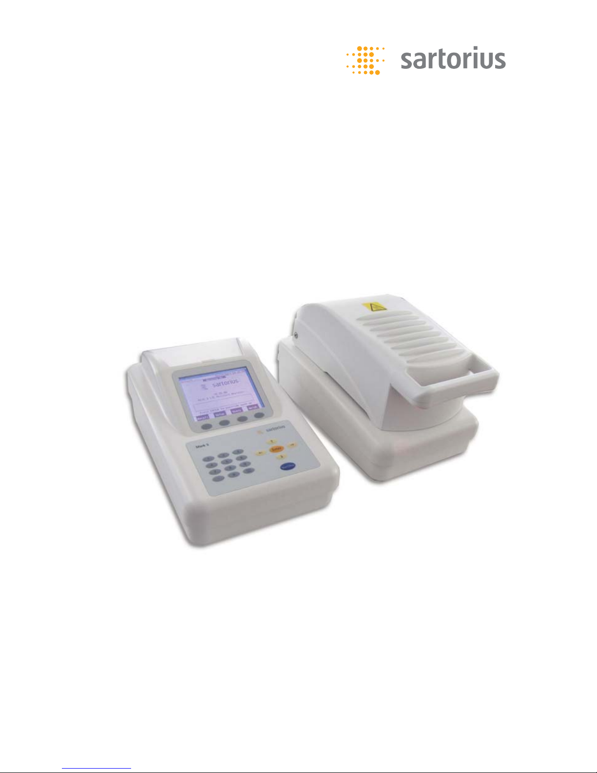
Thank you for choosing the Sartorius
Mark 3 LTE moisture analyzer, the international version of the field-proven Mark
3 from Sartorius. This analyzer is a modular analytical instrument that can be configured to meet various performance
requirements. Each analyzer consists of
two parts, a control module and a heater
module. The control module is comprised
of a keypad, a display and a printer
(optional) with the appropriate electronics. The heater module consists of the
electronic balance and heating cavity. Up
to two heater modules may be interfaced
with a single control module. On initial
power-up, the control module will automatically detect how many heater modules have been connected and are powered on. If more than one heater module
is detected, the analyzer will run in the
Multi-module mode.
The Mark 3 LTE moisture analyzer is used
as a quick and reliable means of determining the moisture content in various
samples by the principle of loss on
drying.
Key features of the Mark 3 LTE include:
§ Sample heating with infrared quartz tubes
§ Precision electronic balance for accurate
weighing and continuous weight monitoring during analysis
§ Quarter VGA screen for easy viewing
§ Large storage of methods for easy recall
of frequently used drying procedures
§ Modular system for add-on capability
of multiple heater modules
Please take the time to read these
Operating Instructions to learn the safe
operation of this analyzer. The Mark 3
LTE has many features that will be
described and can be of benefit to your
moisture testing program.
The Operating Instructions contain
guidance in the form of descriptions,
charts, software flow charts, and
pictorial diagrams:
§ Key names are presented in bold:
Start|Stop
§ Safety symbols indicate notes or caution
of risks as detailed below.
Descriptions and Symbols
Important safety related instructions
are highlighted visually throughout the
Operating Instructions with a description:
Danger
Warning of a possible danger that may
lead to a serious injury.
Caution
Warning of a possible danger that may
result in minor injury or damage.
Note
Important guideline on how to use the
moisture analyzer correctly.
Instrument labels
Caution:
!
Read manual before operating
Danger:
Electrical hazard
Caution:
Hot surface
Page 4

Warning and Safety Information
This moisture analyzer complies
with the European Council Directives as well as international regulations and standards for electrical
equipment, electromagnetic compatibility, and the stipulated safety
requirements. Improper use or
handling, however, can result in
damage and/or injury.
Read these operating instructions
thoroughly before using your moisture analyzer to prevent damage to
the equipment. Keep these instructions in a safe place.
Follow the instructions below to
ensure safe and trouble-free operation of your moisture analyzer:
!
Use the moisture analyzer only
for performing moisture analysis of
samples. Any improper use of the
analyzer can endanger persons and
may result in damage to the analyzer or other material assets.
!
Samples or containers (e.g., beakers
or graduated flasks) that are too
large or bulky to permit complete
closure of the sample chamber
hood must not be placed in the
analyzer.
!
Do not use this moisture analyzer
in a hazardous area/location; operate it only under the ambient conditions specified in these instructions.
– The moisture analyzer may be
operated only by qualified persons
who are familiar with the properties
of the sample to be analyzed.
!
Class A Warning
Warning: This is a class A product.
In a domestic environment this
product may cause radio interference in which case the user may
be required to take adequate
measures.
4
Page 5

!
Make sure before getting started
that the voltage rating printed on
the manufacturer‘s label is identical
to your local line voltage (see the
section on “Connecting the Moisture Analyzer to AC Power” in the
chapter entitled “Getting Started”)
– The analyzer comes with a power
supply that has a grounding conductor
– The only way to switch the power
off completely is to unplug the
power cord.
– Position the power cable so that it
cannot touch any hot areas of the
moisture analyzer.
– Use only extension cords that meet
the applicable standards and have
a protective grounding conductor.
– Disconnecting the ground conduc-
tor is prohibited.
– Connect only Sartorius accessories
and options, as these are optimally
designed for use with your moisture analyzer.
– Protect the moisture analyzer from
contact with liquid.
– If there is visible damage to the
moisture analyzer or power cord:
unplug the equipment and lock it
in a secure place to ensure that it
cannot be used for the time being.
!
Clean your moisture analyzer
according to the cleaning instructions only (see “Cleaning”).
Do not open the analyzer housing.
If the seal is broken, this will result in
forfeiture of all claims under the manufacturer’s warranty.
In case you have any problems with
your moisture analyzer:
$ contact your local Sartorius office,
dealer or service center
Warning: Severe Burns!
– When setting up the moisture analyzer,
leave enough space to prevent heat
from building up and to keep your
analyzer from overheating:
– leave 20 cm (about 8 inches) around
the moisture analyzer
– 1 m (3 ft.) above the device
– Do not put any flammable substances
on, under or near the moisture analyzer,
because the area around the heating
unit will heat up.
– Be careful when removing the sample
from the chamber: the sample itself, the
heater module and the sample pan used
can still be extremely hot.
– Do not remove the heater module unit
during operation: the heating element
and its protective glass panels can get
extremely hot!
– Prevent excess heat build-up around the
analyzer.
5
Page 6

Hazards for persons or equipment
posed by using specific samples:
Fire Explosion
– Flammable or explosive substances
– Substances that contain solvents
– Substances that release flammable or
explosive gases or vapors during the
drying process
In some cases, it is possible to operate
the moisture analyzer in an enclosed
nitrogen atmosphere to prevent the
vapor released during drying from
coming in contact with oxygen in the
surrounding atmosphere. Check on a
case-to-case basis whether this method
can be used, because installation of the
analyzer in too small an enclosed space
can affect its functions (for instance
through excessive heat build-up within
the analyzer). When in doubt, perform
a risk analysis.
The user shall be liable and responsible
for any damage that arises in connection with this moisture analyzer.
Poisoning Caustic burns
– Substances containing toxic or caustic
or corrosive substances: These may
be dried only under a fume hood.
The value for the “lower toxic limit” in
a work area must not be exceeded.
Corrosion:
– Substances that release aggressive
vapors during the heating process
(such as acids): In this case we recommend that you work with small sample
quantities. Otherwise, vapors can condense on cold housing parts and cause
corrosion.
The user shall be liable and responsible
for any damage that arises in connection with this moisture analyzer.
– Sample Pans (Delivered with the
Analyzer):
The reusable metal pans are not
made of stainless steel. For this reason,
they are not resistant to corrosion.
These pans can be used only for powder
and granules (e.g. plastics) with very
low moisture content.
If the moisture content is higher, the
disposable aluminium pans (90 mm
diameter) must be used (see chapter
“Accessories”).
6
Page 7

Caution
Do not touch the metal surfaces inside
the drying chamber while removing
or placing a sample in the analyzer since
the surfaces are very hot.
Do not touch the heater hood ventilation area at any time because this area
can be hot during and after a test.
§ Do not test flammable or toxic
materials.
§ Use the analyzer in a fume hood if the
samples emit fumes which could be
harmful.
§ Know where the fire extinguisher is
located. Use only an extinguisher rated
for use with electrical fires.
§ Keep the analyzer clean. Always unplug
the analyzer and cool it thoroughly
before cleaning or performing service.
§ Do not block the ventilation areas of
the heating chamber.
§ If necessary, press the Start|Stop key
during a test to stop the test.
§ Locate the analyzer away from
flammable materials.
§ If liquid is spilled into the analyzer,
unplug the Heating Module from the
electrical supply immediately.
§ Analyzer is suitable for continuous
operation
Safety Precautions
Danger
Use of this product in a manner
not specified by the manufacturer
may impair any safety protection
provided by the equipment!
Every attempt has been made to
make this analyzer safe and easy to
use. However, like any laboratory
instrument respect must be given
to the operation of the analyzer
due to environmental conditions,
the nature of the samples being
tested and of the chemicals which
might be near the analyzer.
To avoid personal injury or damage
to the analyzer, please observe the
following precautions:
Read all instructions in the Operating Instructions prior to operating
your analyzer.
Warning
Control module contains 3V Lithium
Battery. Please dispose of in accordance with local regulations and
conventions.
7
Page 8

Getting Started
Thank you for choosing the Sartorius
LMA110S moisture analyzer. The
LMA110S is a modular analytical instrument designed to be configured to meet
various performance requirements. Each
analyzer consists of two parts, a control
module and a heater module. The control module contains the keypad, display and a printer (optional) with the
appropriate electronics. The heater
module consists of an electronic balance and heating cavity. Up to two
heater modules may be interfaced with
a single control module. On initial
power-up, the control module will
automatically detect how many heater
modules have been connected and are
powered on. If more than one heater
module is detected, the analyzer will
run in the multi-module mode.
Storage and Shipping Conditions
Allowable storage temperature:
–10 to +50°C
–14°F to +122°F
Allowable shipping temperature:
–40 to +70°C
–40°F...+158°F
Unpacking the Moisture Analyzer
The moisture analyzer is delivered in
a set of two custom-made boxes specifically designed for this precision instrument to provide optimum protection
during transportation.
Note
Retain the original packaging in order
to ship the analyzer if it needs to be
transported or stored at some future
time.
8
Page 9

Follow the instructions carefully when
unpacking the analyzer:
§ Unpack the analyzer carefully and
gently.
§ Remove all the contents of the carton.
Check carefully to make sure you have
removed all accessory items.
§ The LMA110S consists of two modules,
a control module and a heater module.
Up to two heater modules
may be connected to a single control
module.
§ Inspect each module for physical damage and report any damage immediately
to Sartorius or the distributor that you
purchased the analyzer from.
§ Verify that you have received the
following accessories:
Instructions for Recycling
the Packaging
To ensure adequate protection for safe
shipment, your moisture analyzer has
been packaged to the extent necessary
using environmentally friendly materials. After successful installation of the
moisture analyzer, you should return
this packaging for recycling because
it is a valuable source of secondary raw
material. For information on recycling
options, including recycling of old
weighing equipment, contact your
municipal waste disposal center or local
recycling depot.
Equipment Supplied
– Inter-module cable
– Power module cable
– Pan support
– Pan shield
– Power cord
– Tweezers
– Sample pans
– Operating instructions manual
9
Page 10
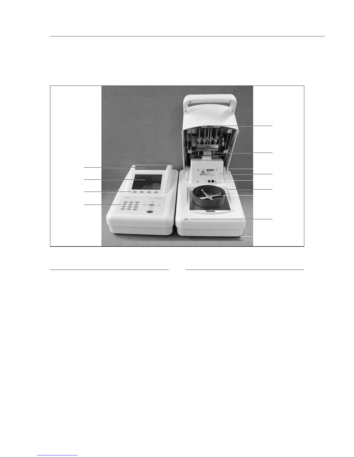
General Views of the Moisture Analyzer
No. Designation
Heater Module
1 Pan shield
2 Pan support
3 Cylindrical quartz heating tubes
4 RTD temperature sensor
5 Heater adjustment tool connector
6 LED status lights
7 Service panel, heaters & RTD
temperature sensor
8 Level vial
9 Adjustable leveling feet
10 Inter-module cable receptacle
11 Main power switch
12 Main cord receptacle
13 Fuse 1 (250 V~5A T)
14 Fuse 2 (250 V~5A T)
15 Module power cable receptacle
No. Designation
Control Module
16 Storage Bin
17 VGA display
18 Soft keys and display overlay
19 Keypad
20 Inter-module cable receptacle
21 Module power cable receptacle
22 Ethernet socket: only for Sartorius
Service
23 USB socket: only for Sartorius
Service
Cables and Power cord
24 Serial connector
25 Inter-module cable
27 Main power cord
10
16
17
18
19
4
3
8
7
5
1
2
6
9
Page 11
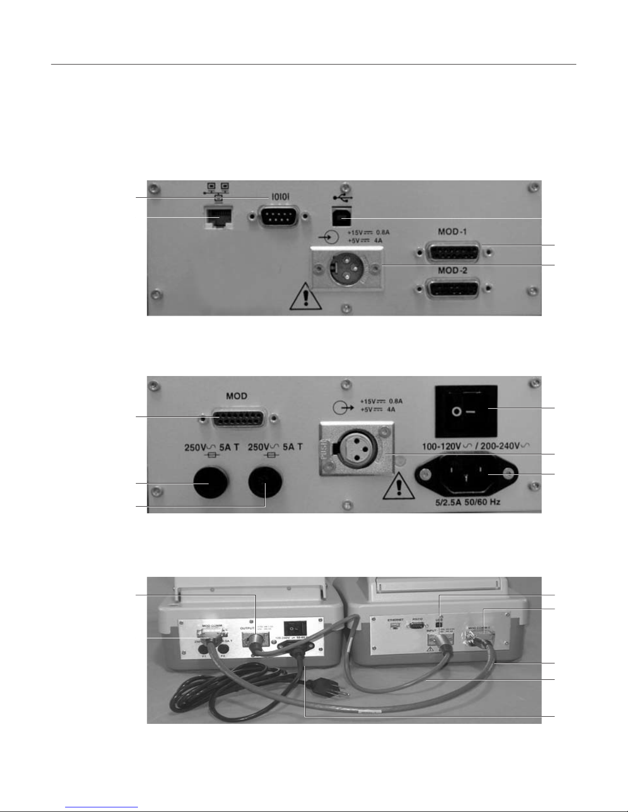
Control Module Connector Panel
Heater Module Connector Panel
Cables Connected to Control and Heater Modules
11
23
20
21
11
15
12
21
20
25
26
27
24
22
10
13
14
15
10
Page 12

Assembly
The analyzer does not come fully
assembled. The control and heater
modules are placed next to each other
and may be placed on either side of
each other. Assemble the modules and
individual components in the following
order:
1. Open the heater hood using the handle
and install the pan shield so that the
center hole fits over the center ring of
the cavity base plate.
2. Next, place the stem of the pan support
through the center ring of the base
plate and into the hole of pan receiver.
3. Remove the foam from the heater
chamber.
4. Connect the power module cable
between the control module and the
heater module, observing the pin orientation.
5. Connect the inter-module cable
between the control module (MOD
COMM 1 connector) and the heater
module, observing the connector orientation.
6. If multiple heater modules are used,
install the additional inter-module
cables from each heater module to the
control module inter-module cable
receptacle (MOD COMM 1-2). Refer to
the chapter in this manual on multimode operation for instructions specific
to operating multiple heater modules.
12
Page 13

Choosing a Suitable Location
In order to ensure that the analyzer
functions properly, select a location that
meets the following requirements:
§ Permissible ambient environment
– Temperature:
+15 to +40°C (59°F to 104°F)
– Relative humidity:
10 – 85%, non-condensing
– Altitude:
0 to 2,000 meters (0 to ~6562 ft)
§ The analyzer is intended for indoor use.
§ Place the analyzer on a rigid, horizontal
surface, preferably free of vibration.
§ Avoid drafts and excessive temperature
fluctuation.
§ Locate the analyzer away from
flammable materials.
Connecting the Moisture Analyzer
to AC Power
This Class I Equipment (grounded
type) analyzer contains a universal
self-adjusting power supply rated to
100-120/200-250V~5/2.5A 50/60 Hz.
Check that this voltage matches your
local line voltage. If your voltage is not
within this rating, do not connect the
power cord to the power supply.
Danger
! The analyzer may only be operated
using the original power cord supplied.
Please do not use it with an extension
cord. The wall socket must be grounded.
The AC Power mains supply fluctuations
are not to exceed +/–10% of the nominal supply voltage. The (Over Voltage)
Category II for transient over voltages
is EN 61010-1. The pollution Degree 2
is supplied EN 61010-1. The analyzer
is rated to Normal Protection (not
protected against harmful ingress of
moisture).
§ Insert the power cord that with the
analyzer into the power input receptacle
on the back of the heater module.
§ Then plug the power cord into a wall
socket.
§ Turn the analyzer on by moving the
power switch on the back of the analyzer
to the On position. The analyzer will
briefly proceed through a self-diagnostic
routine and then display the standby
screen. It will automatically enter a
warm-up period as noted on the screen.
Should the analyzer display any warnings, consult the troubleshooting section of this manual, or call Sartorius.
13
Page 14

Leveling the Moisture Analyzer
In order to function properly, the heater
module should be horizontal. The heater
module has a level vial. You can tell
when the analyzer is level by checking
whether the bubble is centered in the
vial.
§ Check that all four feet are in the fully
inserted position.
§ Observing the level vial, rotate one foot
at a time to level.
Adjust control module so that it does
not rock.
Note
The heater module must be re-leveled
each time the analyzer is moved.
LMA110S Keypad
Warm-up
To enable the analyzer to function
optimally, plug it in and leave it powered on for a minimum of 15 minutes.
The analyzer is preprogrammed to alert
the operator that the device is in the
warm-up period. It is best to allow the
analyzer to complete this warm-up
period before testing samples; however,
this may be overridden by pressing the
Enter key.
14
Numeric
keys
Soft keys
Navigational
keys
Page 15

Operating Design
The Mark 3 LTE analyzer is operated
through the keypad in conjunction
with the quarter VGA screen. The
Mark 3 LTE is preprogrammed with
operational and setup software that
enables the analyzer to be custom
configured to meet the particular
needs of the application, environment or user ability.
Keypad
The analyzer has two membrane
type keypads: the main keypad and
a second that also serves to sealed
the display. The keypad consists of
three dedicated keys, numeric keys,
navigational keys and soft keys.
The following is a description of
each of the key functions:
Dedicated keys:
Each key has a particular function.
Pressing the key once will initiate the
desired action.
Initiates the testing of a sample
Stops a test in progress
u Press to finalize the entry of
a numeric value
– Selects the highlighted menu
selection in a list
– From the Standby screen will print
the last result
Start|Stop
Numeric and Decimal Point Keys
Numbers from 0 to 9 and the decimal point are pressed either to enter
a specific numeric value or to make
a selection from a list of menu
choices preceded by a number.
Navigational Keys
Four keys are intended to move the
highlighted cursor on the screen in
a particular direction.
Moves the cursor to the right
Moves the cursor to the left
Moves the cursor up
Moves the cursor down
15
Page 16

Soft keys:
The functionality of these keys will
change depending on what is on the
display. A label on the display just
above the key will describe the key
function at the moment.
Some examples of the soft keys are
as follows:
Prints various items corresponding to
the menu selection
Toggles a highlighted selection
between on and off
Used to select a drying program from
the Program menu
Access to all setup parameters from
the Setup menu.
Setup
Recall
On/off
Print
Used to select an operator. Name will
be printed on the results printout.
Display will return to the previous
menu.
Display will return to the Standby
menu.
Deletes the single highlighted
character when entering alphanumeric program names and operators.
Sets analyzer to the weighing mode.
Weigh
Delete
Users
16
Page 17
Display Modes
The large quarter VGA display is designed to make
operation and setting up the analyzer easy through
of detailed information in clear descriptions, choices
or menus. The analyzer will display information in
several different formats as described below:
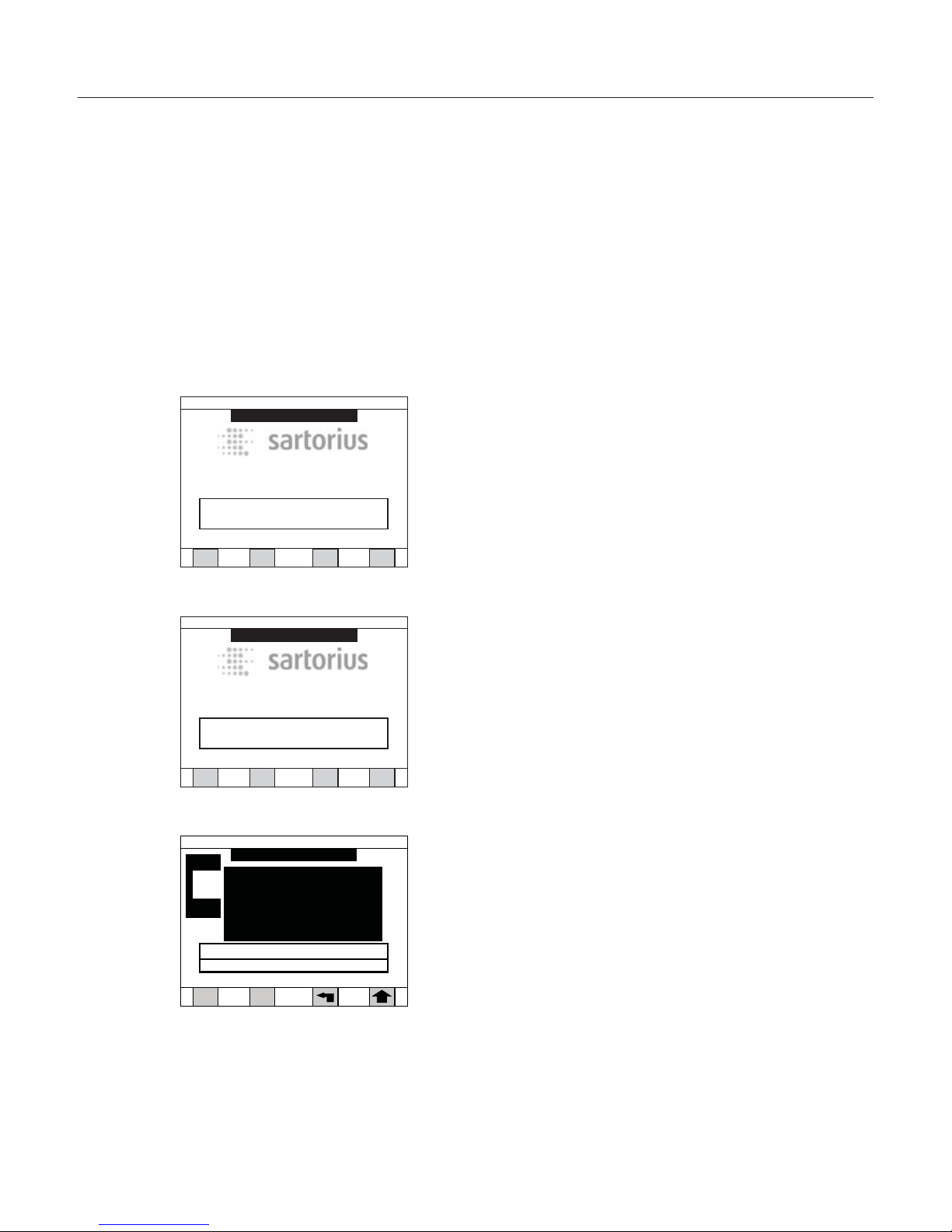
Warm-up:
This mode is entered whenever the analyzer is powered on. The warm-up period ensures that the analyzer is properly conditioned before testing is begun.
During warm-up the screen will be mostly blank.
Standby (or Test Done):
In this mode the analyzer is in an ideal status.
This is the period between testing samples.
The temperature of the chamber is controlled to a
particular level based on the Standby temperature
set for the last test performed. The screen will display
the program name, date and time, temperature and
the last result, if a test has been run.
Test:
This mode is entered when the Start|Stop key
is pressed to initiate a test. The screen is similar in
design to the Standby mode but also includes
prompts to guide the operator through the steps
of adding a sample, entering an ID, if desired, and
displaying the result when the test is completed.
Default
05/01/2011 02:14 PM
WARMIN G UP
Ver. 1.00.00
Mark 3 LTE Moisture Analyzer
Recall
Setup
Weigh
Users
Press ENTER to override warm up
Default
05/01/2011 02:14 PM
WARMIN G UP
Ver. 1.00.00
Mark 3 LTE Moisture Analyzer
Recall
Setup
Weigh
Users
Press ENTER to override warm up
Add sample to pan
DRY MILK POWDER
05/01/2011 02:14 PM
Module 1
0.000
g
Zero
{ }
0%
Standby
Current
60
57
17
Page 18

Graph:
The graph mode can be entered during or after
a test to show a graph of the weight versus time,
temperature versus time, or result versus time.
Data Log:
The data log mode is used for reviewing past
samples that have been tested. The log of samples
can be sorted, or samples can be manually selected
to perform statistical calculations.
18
Temperature / time
DRY MILK POWD ER
05/01/2011 02:14 PM
Print Result
210
30
0.5 1.0 1.5 2.0 2.5 3.0
3.5 4.0 4.5 5.0 min
25.67 %
View Data Log
Down Up
Top
Dry milk power 05/01/2011 02:10
3.45%M 6.7min 672001
Dry milk power 05/01/2011 02:02
3.50%M 6.8min 672002
Dry milk power 05/01/2011 01:53
3.47%M 7.0min 672003
05/01/2011
02:18 PM
Page 19

Menu Structure
The Mark 3 LTE set up software is structured
according to a series of menus. The Setup menu lists
several topics of instrument setup. By drilling down
into these topics, sub-menus will allow specific
choices to be selected. See the Setup section for
details.
How to navigate in the menu structure:
§ To select a menu and to drill down to more specific
information:
– Press the preceding number key of this listing or
– Use the navigational arrow keys to highlight the
desired listing first, then press the Enter key
§ To return to a preceding menu level, press the arrow
soft key. Subsequent presses will return you to the
Standby screen.
§ To return to the Standby screen, press the bent
arrow if one is available from that screen. To choose
a specific selection option or to enter a value:
A selection can be made by:
– Pressing the preceding number key of this listing,
or
– Using the navigational arrow keys to highlight the
desired listing first, then press the Enter key.
§ How to make a numeric input:
– Use the numeric keypad to enter a value fist, then
press the Enter key.
19
1)Program manage
2)Data log
3)Modify operators
4)Results printout format
5)Time and date
6)Communication ports
7)Conserve mode
8)Security
9)Audio & video
0)Module port scan
. ) Service
Setup Menu
05/01/2011 02:18 PM
Page 20

Data Output
LED Status Lights
The Mark 3 LTE heater module has two
LED lights on the front left corner that
visually indicate the status of the analyzer. The left LED shows the status of
the balance. The right LED indicates the
status of the heating function.
Each LED may have three colors:
red, green or amber. Red is generally
associated with a warning state and
shows that corrective action must be
taken. Green is generally associated with
a positive condition, indicating you can
proceed. Yellow generally indicates
a transitional period or that the test
is in progress.
20
Warmup
Balance LED
Heater LED
Warming up
Rapidly ashing RED Rapidly ashing RED
Ready to test
Steady GREEN Steady GREEN
Heater in conserve mode
Steady GREEN Steady YELLOW
Standby
Balance LED Heater LED
Sample in chamber
heating cavity (chamber)
Flashing YELLOW Flashing GREEN
Test mode Balance LED
Heater LED
Test in progress Steady YELLOW
Steady YELLOW
Test done
Flashing YELLOW Flashing GREEN
Sample loading
Below target
Flashing GREEN
Steady GREEN
Within target Flashing YELLOW
Steady GREEN
Above target Flashing RED
Steady GREEN
Diagnostics Balance LED
Heater LED
Failed diagnostics
Flashing RED
Flashing RED
Page 21

The Mark 3 LTE Moisture Analyzer is designed to
test moisture content in a large variety of materials
including powders, pastes and liquids. The performance of the analyzer is dependent upon selecting
optimum drying analysis conditions for your specific
sample type. Sartorius will support you in finding
the set of testing parameters (referred to as a program) you need for your specific tests. On request,
we will provide a chart of the parameters and test
results we have compiled by testing samples in our
laboratory and comparing the results to those
obtained by reference methods.
If our chart of applications shows a drying program
that is not already programmed into your analyzer,
you may do this yourself by following the instructions under Setup in this manual.
Standby Screen
During warm-up, your analyzer will enter the Standby mode and the Standby screen will be displayed.
It is from the Standby (or Test Done) screen that all
functions of operating the analyzer, including testing samples and setting parameters, take place.
The standby screen shows the following
information:
§ Program name
§ Time and date
§ Standby temperature and actual temperature
§ Various soft keys for options that are available
depending on the security setup options engaged
§ Warnings that will need to be addressed before
testing
21
Operating
the Moisture Analyzer
DRY MILK POWDER
Standby
Recall Setup
Weigh Users
Press START key to begin test
Standby
Current
60
59
05/01/2011 02:18 PM
Ver. 1.00.00
Mark 3 LTE Moisture Analyzer
Page 22

Functions available from the Standby screen:
§ Press Start|Stop key to initiate a test
§ Press Recall soft key to change the program to
be used for testing a sample
§ Press User soft key to select an operator name
(feature must be turned on in Setup)
§ Press Setup soft key to enter the Setup menu in
order to make all parameter changes
§ Press Graph soft key to display a graph
§ Press Weigh soft key to use as a balance
Standby-Temperature
!
with a New Program
When creating a new program, the standby
temperature setting from the previous drying
program is used automatically by the analyzer.
Example:
You have created a new program for drying
a temperature-sensitive sample at low temperature. The analyzer uses the standby temperature, e.g. 165°C, from the previous program.
You must call up the standby temperature
parameter and change the temperature value.
If you forget performing this setting, your analyzer is always too hot before starting the test.
22
Page 23

Default Drying Program
Your analyzer is delivered with a default drying program. The drying program contains all the specific
parameters to test a sample including temperature,
endpoint, unit of measure, standby temperature,
etc. You will notice if you are in the default program
or a specific material program by the program name
at the top left of the display.
23
Program name: Default
Temp1=105C
Time1=Off
Temp2=Off, Time2=Off
Slope=0.050%/1 minute, Actual
Start delay=0 second
Standby temp=60C, Ideal weight=5g, Lock=Off
Target limits=Off
Mode=Standard
Page 24

Recalling a Program
Drying programs are stored for easy access at a later
time. This eliminates the need to change parameters
for frequently tested samples. Up to 60 drying programs can be stored. Creating and storing a program
is described under Developing a Drying Program.
To recall a stored program, perform the following
steps:
1. From the Standby screen, press the RECALL soft key.
The screen will change to the first page of stored
programs as show below.
2. To display programs on the next pages, press the
Down soft key.
3. Press the number(s) key followed by the Enter key
for the number that precedes the program name.
As an alternative, use the arrow keys to highlight the
desired program name, then press Enter. The display
will change to the Standby screen with the new
program in the top left corner. This program will be
used for the next test. If a blank program is entered,
the analyzer will use the last valid program that
was entered.
Note
As a shortcut, it is not necessary to have the desired
program listed on the display to recall it. Simply
enter the desired number from your memory on the
first page and press the Enter key.
24
11)
2) Whey Protein 12)
)3
1 )3
)4
1
)
4
)5
1
)
5
)6
1
)6
)71 )7
)8
1
)
8
)91
)9
)0
2
)01
Programs
Program #:
Down
1)
Dry Milk Powder
Up
_
Top
05/01/2011 02:18 PM
Page 25

Testing a Sample
A test can only be initiated from the Standby or Test
Done screen. The program that will be used is shown
in the upper left corner.
To test a sample, perform the following:
1) Open the hood of the heater module using the
handle on the front of the analyzer.
Caution
The heater hood will be hot during testing and the
standby mode.
Only touch the heater hood by the handle.
2) Place one pan onto the pan support and close the
heater hood.
3) From the Standby screen, press the Start|Stop key.
The display will change to the test mode as shown
on the left. The balance will automatically tare and
show zero weight on the screen.
Note
If you forgot to place the pan onto the balance
ahead of time, you may open the heater hood now,
add the pan, close the heater hood and manually
tare by pressing the Zero soft key.
25
DRY MILK POWDER
Standby
Recall Setup
Weigh Users
Press START key to begin test
Standby
Current
60
59
05/01/2011 02:18 PM
Ver. 1.00.00
Mark 3 LTE Moisture Analyzer
Sampling
DRY MILK POWDER
Module 1
0.000
g
Zero
{ }
0%
Standby
Current
60
57
05/01/2011 02:19 PM
Page 26

4. At the “Add sample to pan” prompt, open the heater
hood and begin adding sample to the pan. A bar
graph on the display will guide the operator to place
the correct amount of sample as set by the ideal
weight parameter of the drying program. Continue
adding sample until the beeper sounds, indicating
that the sample amount is within 10% of the ideal
weight. The exact weight is also displayed on the
screen.
5. At the “Close heater hood” prompt, close the heater
hood. The balance will capture the initial weight of
the sample “Sampling” and then show that the test
is in progress. The display will change to show current information including the elapsed time and the
current percentage weight loss in the units as specified in the drying program.
Note
To stop the test in progress, press the Start|Stop key.
The optional printer will begin to print as the test
begins. Printout information can be selected in
Setup menu under Printer.
At the end of the test the display will show “Test
Done.” The result will stay on the screen as well as
be printed. The analyzer will enter the Standby
mode until the next test is initiated.
26
Dry Milk Powder
Test in Progress
0.01
% Moisture
Elapsed time: 00.10
Graph
Press STOP key to stop test
Temp 1
Current
105
71
05/01/2011 02:18 PM
Press START key to begin test
Dry Milk Powder
Test Done
3.47 % Moisture
Result time: 7.0 min
ID: 126399.1
Target: Pass
Recall Setup
Graph User
Warning: Sample on pan
Standby
Current
105
105
05/01/2011 02:18 PM
Page 27

The display will prompt you, the
operator to remove the sample
before the next sample can be tested. Open the hood and carefully
remove this sample using tweezers,
and while the hood is open, add
the sample pan for the next sample
to be tested.
Caution
!
The sample is hot during and after
the test. Remove the sample with
care by using the tweezers provided
with the analyzer. Do not touch
any internal part of the heating
chamber or pan shield as they will
be very hot.
Press the Start|Stop key to begin the
next test using the same program.
Note
The analyzer balance must be calibrated
before putting the unit into routine
service. See the section on Calibrate
Balance in this manual.
27
Page 28

Setup Menu
All settings for to the Mark 3 LTE, including changing of instrument options and program parameters,
are selected in the Setup menu. Each subject is listed
on the Setup menu screen.
To enter the Setup menu:
§ From the Standby screen, press the Setup soft key to
display the Setup Menu screen.
Note
Pressing the arrow soft key from the Setup menu or
any submenu will always take you back one level.
Setting the Device Parameters
in the Program Manage Menu
The Program Manage Menu provides access to all
setup functions associated with creating, editing, or
managing sample drying programs.
To enter the Program Manage Menu:
§ From the Setup menu screen, press the 1 key
or highlight “Program manage”, using the navigation keys and press Enter.
28
1)Program manage
2)Data log
3)Modify operators
4)Results printout format
5)Time and date
6)Communication ports
7)Conserve mode
8)Security
9) Audio & video
0) Module port scan
.
) Service
Setup Menu
05/01/2011 02:31 PM
Page 29

Edit Current Program
All parameters associated with a currently stored
drying program can be edited and re-stored or
changed without re-storing. The program to be
edited will be in the top left corner of the display.
If this is not the program you wish to edit, then
it must first be recalled.
To edit a current program:
§ From the Program manage menu, press the 1 key to
display the Program Menu screen.
All the parameters of the drying program are
displayed on this screen for the program named in
the top left corner. To make a change to any of the
parameters, enter the submenu for that topic.
A complete list of all variables for each parameter
is shown on the next page.
To edit a current program without storing:
§ Make the change, then press the arrow key to return
one level.
§ Alternatively make the change, then press the bent
arrow key to return to the Standby screen. On the
Standby screen, the warning will show that the
changes have not been saved.
To save an edited program:
§ Make changes, then press the Save soft key to
return to the Standby screen.
29
Default
Program Manage Menu
1)Edit current program
2)Create new program
3)Delete program
4)Sort programs (alphabetize)
5)Sort programs (fill in blanks)
6)Print current program
7)Print program list
8)Print all programs
05/01/2011
02:18 PM
1) Unit Moisture (0.00%)
2) Temp 1 105C, std, Time 1 O
3) Temp 2 O, Time 2 O
4) Slope 0.05%/1min, actual
5) Start delay 0 sec
6) Standby temp 60C, Equilibrate O
7) Ideal weight 5g, lock O
8) Target limits O
9) Mode Standard
0) Program name Default
Press Save soft key to save changes.
Program Menu
Default
05/01/2011 02:18 PM
Print
Save
Page 30

Table: Program Settings
Screen Parameter Variables Explanation
Units Units Moisture Initial wt. – final wt. / Initial wt. + 100
Solids Final wt. / Initial wt. + 100
Volatiles Initial wt. – final wt. / Initial wt. + 100
Moisture/dry Initial wt. – final wt. / Final wt. + 100
mg/l Final wt. + 1000 / volume in mL
Weight Initial wt. – final wt.
Result display Decimal place 0.01% or 0.001%
Factors Scale factor Factored result = (result + scale factor) + offset
Offset Factored result = (result + scale factor) + offset
Temperature 1 Temperature Maximum 210°C Set temperature or Off
Time 10.0 – 99.9 minutes Set time or Off
Temperature 2 Temperature Maximum 210°C Set temperature or Off
Time 20.0 – 99.9 minutes Set time or Off
Slope % Initial weight 0.01 – 9.99 Weight variable of endpoint criteria
Window of time 0.1 – 99.9 minutes Time variable of endpoint criteria
Calculation Actual slope Slope criteria met for endpoint
Calc 1 Calculated endpoint
Calc 2 Calculated endpoint
Calc 3 Calculated endpoint
Start delay Start delay 0 - 9 seconds Delay before starting test
Mode Mark 2 Simulates Mark 2 start delay
LMA110S LMA110S start delay
Standby temp. Standby temp. Maximum 165°C Set temperature between tests
Ideal weight Ideal weight 0.1 – 99.0 g Set ideal sample weight for test
Percent 1 – 10% Set tolerance of ideal weight
Ideal weight Lock On or Off Set ideal weight lock strict (On) or Off
Target limit Target limit Upper limit Set upper limit of result tolerance
Lower limit Set lower limit of result tolerance
Turn limits Off Turns target limit feature Off
Mode Mode Standard Standard test mode
Concentration Corrects a result for sample volume
30
Page 31

Units
The analyzer will calculate the test result in a variety
of units of measure, depending on your specific
application. This menu also provides access to the
advanced options associated with units: displayed
readability and correlation factors.
To change the unit of measure:
§ Press the 1 key from the Program Menu to display
the Units menu. The current unit will be shown.
§ Press a number key for the new unit of choice.
§ Note that there is an advanced option indicated by
Factor on the soft key. To change this feature, see
“Factors.”
§ When all the parameters for units have been
changed, then press the arrow soft key to accept
the changes. The display will return to the Program
Menu.
31
Current units: Moisture
1)Moisture
2)Solids
3)Volatiles
4)Moisture/dry
5) Weight
Units
Default
Factors: active
05/01/2011 02:24 PM
Factor
Page 32

Factors
The analyzer has a feature for entering a scale or
offset factor to adjust the result to a more accurate
value. Only under special circumstances will either of
the factors ever be used.
To set or change factors:
§ Press the 1 key for Units to display the Units screen.
§ Press the Factor soft key. The display will change to
the Factors screen.
§ Press the 1 or 2 key to display either the scale factor
or offset screen.
§ Enter the desired value and press the Enter key
to return to the Factors screen.
§ Press the Arrow soft key to return to the Units
screen.
(result) · (scale) + offset
32
Current units: Moisture
1)Moisture
2)Solids
3)Volatiles
4)Moisture/dry
5) Weight
Units
Default
Factors: active
05/01/2011 02:24 PM
Factor
Factors
Default
1) Set scale factor: 1.000
2) Set offset: 0.000
Enter the scale and offset
to apply to the result calculation:
(Result)*(Factor) + Offset
05/01/2011 02:21 PM
Page 33

Temperature 1 and 2
The analyzer will dry the sample at one or two
temperatures set in one degree of Celsius increments. A second temperature is optional and is normally set to Off. See the Applications section for a
description of when to use a second temperature for
two-step drying.
To set or change Temperature 1 or Temperature 2:
§ Press the 2 or 3 key for Temp 1 or Temp 2,
respectively. The display will change to the Temp 1
or Temp 2 screen. The current temperature will be
shown.
§ Using the numeric keys, type in the desired temperature and press Enter.
§ Note that there are some advanced options indicated
by Ramp and Time 1 (or 2) on the soft keys. To
change these features see, “Time 1 and 2.”
§ When all the parameters for Temperature 1 or 2
have been changed, press the Enter again or the
Arrow key to accept the changes. The display will
return to the Program Menu.
33
Temperature: 105 C
Max. Temperature: 210 C
Time: 99.9 minutes
Temperature 1
Default
| C
Clear
Time
05/01/2011 02:21 PM
Page 34

34
Time 1 and 2
Each the Temperature 1 and 2 setting
can have a set period of time. Time 1 or
2 is the time during which the sample
will be dried at each temperature before
advancing to the next temperature.
Once the time for the last temperature
has elapsed, the test will terminate
unless a slope endpoint has been turned
On. If Temperature 2 is set, then at the
end of Time 1, the analyzer will ramp to
Temperature 2.
To set or change Time 1 or 2:
§ Press the Time 1 or Time 2 soft key to
display the Time 1 or Time 2 screen.
§ Use the numeric keys type in the desired
temperature, then press the Enter key.
The display will return to the Temperature 1 or 2 screen.
Slope
The slope function provides an automatic endpoint for the test. The slope
function consists of two variables:
window of time and percent of initial
weight (%IW) change. During the test,
the weight change of the sample is continuously monitored within a moving
window of time. When the loss of
weight within the window is less than
the initial weight percentage set, the
slope criteria has been met. The final
weight is taken and calculation is
performed to end the test. This slope
is referred to as “actual slope” because
the endpoint is actually achieved.
Tim
e
W
e
i
g
h
t
% of I.W.
W
indow of time
End of test (Endpoint)
W
Page 35

To set or change slope:
§ Press the 4 key from the Program Menu to display
the Slope screen. The current initial weight percentage is shown.
§ Use the numeric keys type in the desired %IW, then
press the Enter key.
§ Note that there are some advanced options indicated by Time and Calc on the soft keys. To change
these features, see “Windows of Time” or “Calculation Endpoint.”
§ When all the parameters for Slope have been
changed, press the Enter again or the Arrow key to
return to the Program menu.
Window of Time
To set or change window of time:
§ Press the Time soft key to display the Window of
time screen.
§ Use the numeric keys to type in the desired window
of time, then press the Enter key. The display will
return to the Slope screen.
Endpoint Calculation
There are three additional advanced slope settings
called Calc 1, Calc 2 and Calc 3, which are algorithms that calculate the endpoint prior to achieving
the actual slope. These will provide more rapid
results on some samples; however, the success of the
Calc mode varies from case to case.
To set or change Calc endpoint:
§ Press the Calc soft key to display the Calc menu.
§ Press a number key to select the desired calculation
setting. The display will return to the Slope screen.
§ If developing a method, check the correlation of
each Calc mode starting with Calc 1 to the actual
endpoint result.
35
Enter percent of initial weight: 0.05
Range: 0.00 to 9.99%
Enter 0.00 to turn off slope
Time: 1.0 Minute
Calculation: Actual
Slope
Default
| %
Time
New
Calc
05/01/2011 02:24 PM
Page 36

Start Delay
The start delay is a time in seconds that can be set
to ensure that a good initial weight is taken at the
beginning of the test.
To set or change start delay:
§ Press the 5 key from the Program Menu to display
the Start delay screen. The current start delay is
shown.
§ Use the numeric keys to type in the desired %IW,
then press the Enter key.
§ Note the mode: Mark 2 or LMA110S. If in the Mark 2
mode, start delay will simulate the previous Mark 2
analyzer. Press the Mode soft key to toggle between
Mark 2 and LMA110S.
§ Press the Enter key again or the Arrow soft key to
return to the Program Menu.
Standby Temperature
The standby temperature is the temperature that
the analyzer chamber will be controlled to at the
end of a test or prior to a test when a new program
is recalled.
To set or change standby temperature:
§ Press the 6 key from the Program Menu to display
the standby temperature screen. The current standby
temperature is shown.
§ Use the numeric keys to type in the desired standby
temperature, press the Enter key.
§ When all the parameters for slope have been
changed, press the Enter key again or Arrow key to
return to the Program Menu.
36
Enter standby temp: 60 C
Maximum temperature 165 C
Standby Temperature
Default
| C
Clear
05/01/2011 02:31 PM
Page 37

Ideal Weight
The ideal weight is the amount of sample in grams
that should be used for the test as prompted with
a bar graph and beeper in the Test mode.
To set or change the ideal weight:
§ Press the 7 key from the Program Menu to display
the Ideal Weight screen. The current ideal weight
is shown.
§ Use the numeric keys to type in the desired ideal
weight then press the Enter key.
§ Note that there are some advanced options indicated by Lock and % on the soft keys. To change these
features, see “Ideal Weight Percent Limit” and “Ideal
Weight Lock.”
§ When all the parameters for slope have been
changed, press the Enter key again or the Arrow key
to return to the Program Menu.
37
Enter ideal weight: 5.0 g
Range: 0.1 –39.0 g
Ideal weight percent: 10%
Lock: Off
Ideal weight
Default
| g
Lock
Clear
%
05/01/2011 02:24 PM
Page 38

38
Ideal Weight Percent Limit
The ideal weight limit is a tolerance
range for the ideal weight in percent
that the sample weight must be in.
Example: If the ideal weight is 10 grams,
and the target limit is 10%, then an
acceptable sample weight is between
9 and 11 grams.
To set or change the Ideal weight percent limit:
§ Press the % soft key to display the Ideal
weight percent screen.
§ Use the numeric keys to type in the
desired time, press the Enter key. The
display will return to the Ideal Weight
screen.
Ideal Weight Lock
When activated, the ideal weight lock
prevents the use of any other sample
weight other than the one that is within
the target limits. If the lock is not activated, when in the test mode, the target
weight guide is still shown but any
sample weight can be used for the test.
To set or change ideal weight lock:
§ Press the Lock soft key to toggle On or
Off on the Ideal Weight screen.
Page 39

Target Limits
The Target limit Menu provides a statistical process
control (SPC) feature that can be set to identify
when a tested sample is within or outside the desirable limits selected. If this feature is activated, a Pass
or Fail will be displayed after each test, indicating
the sample is within or outside the set limits; this
will also appear on the printout.
To turn the Target Limits feature on and to enter
limits:
§ Press the 8 key from the Program Menu to display
the Target Limits screen. The current target limits
are shown.
§ Press the On|Off soft key to toggle target limits: On
§ Press the 1 key to set the upper limit.
§ Press the 2 key to set the lower limit.
When all the parameters for target limits have been
changed, press the Arrow key to accept the changes.
The display will return to the Program Menu.
39
1. Upper Limit 100.00% Moisture
2. Lower Limit 0.00% Moisture
Target Limits Menu
Default
On/off
05/01/2011 02:24 PM
Page 40

40
Test Mode
This feature provides a few special test
modes for specific applications:
§ Standard: normal test mode where a
sample is placed directly onto the pan
or pan with sample pads to take a direct
weight of the initial weight.
§ Concentrate: used for determining total
suspended solids in low solid samples.
The sample solids are first concentrated
onto a filter pad placed in a vacuum
apparatus. During the test mode, the
operator will then be prompted to enter
the number of milliliters of sample that
was filtered. Results are displayed in
mg/l. See details in the chapter on
Concentration Mode in this manual.
To change the test mode:
§ Press the 9 key from the Program Menu
to display the Mode screen.
§ Press the number key for the mode of
choice. The display will return to the
Program Menu.
Page 41

Program Name
Each program is stored by a unique program name.
Your analyzer may be preprogrammed with a default
set of programs or a set customized for your
company. Program names can be alphanumeric
and have some characters.
To change or set the program name:
§ Press the 0 key from the Program Menu to display
the Program Name screen.
§ Use the navigational arrow keys, up and down,
to enter letters, symbols or a space at the cursor.
Pressing the up arrow key first shows a space, then
scrolls through the alphabet starting with “A”
forward, followed by symbols. Pressing the
down arrow scrolls through the symbols followed
by letters in backwards order. To change to lower
case letters, press the Lower soft key.
§ After selecting the first character, press the navigational arrow right key to move to the cursor to the
next character space and repeat the process.
§ The navigational arrow left key moves the cursor
left.
§ When finished entering the program name, press the
Enter key to return to the Program Manage menu
Menu.
41
Program name: Default
Enter numbers with keypad
Program Name
Default
Lower
Clear
Delete
05/01/2011 02:24 PM
Page 42

42
Create a New Program
The analyzer will store 60 drying programs. New programs can be created
and stored for routine usage. All drying
program parameters are set as described
in “Edit Current Program” on page 30.
When creating a new program, the
parameters will be used of the last program to be recalled.
Note
When creating a new program, you will
edit the last program to be recalled and
shown on the Program Menu screen.
However, you will need to give it a new
program name for storing. Therefore,
first choose a program that is most similar to your new program to minimize
the amount of changes to make.
To create a new program:
§ From the Program Manage menu press
the 2 key for “Create new program” to
display the Program Menu screen.
§ The program name will be labeled
“New.” Change program to your desired
name.
§ Finish making changes to all program
parameters as desired.
§ Press the Save key to store the new
program in the first available blank
program slot.
Note
Programs will be saved when downloading a new software version.
Delete Program
At times you may want to delete
a drying program that you will no
longer need.
To delete a program:
§ From the Program Manage menu, press
the 3 key to go to the Delete screen
showing the list of programs.
§ Type in the number of the program you
want to delete or move the highlight
with the navigation arrow keys and
press the Enter key. The screen will
return to the Program Manage menu.
Sort Programs
Programs can be sorted in two ways
to make them easier to view when
recalling programs:
§ Alphabetical: sorts by alphabetical order
starting with characters, numbers and
then letters.
§ Fill in the blank: removes all the blank
program positions and places programs
in the storage positions starting at 1 in
the same order as before the sort.
To sort programs:
§ From the Program Manage menu, press
the 4 or 5 key. The display will change,
indicating that the analyzer is sorting.
When finished, the display will return to
the Program Manage menu screen.
Page 43

Configuring the Printout
Print Current Program
To print the parameters of the current
program as shown in the top left corner
of the Program Manage menu screen:
§ From the Program Manage menu, press
the 6 key. The current program will be
printed.
Print Program List
To print the entire list of programs:
§ From the Program Manage menu, press
the 7 key. The list of programs will be
printed.
Print All Programs
To print all programs with parameters:
§ From the Program Manage menu, press
the 8 key. The list of programs with
parameters will be printed.
43
Page 44

Data Log
The analyzer will store the last 999 test results.
Results can easily be sorted, viewed on the display or
printed. In addition, you can perform statistical
analysis on sorted or selected results for viewing or
printing. Sorted data may be also downloaded.
Note
The default setting for the data log is Off.
To store data to the data log, it must be turned On
first. Results in the data log are saved when dowd
loading a new software version.
To enter the data log:
§ From the Standby screen, press the Setup soft key to
display the Setup menu screen.
§ Press the 2 key or highlight “Data log” and press the
Enter key to display the Data Log menu.
To enable data to enter the data log:
§ From the Data Log menu, press the On|Off soft key
to toggle data log to On.
To prevent data from entering the data log:
§ From the Data Log menu, press the On|Off soft key
to toggle data log to Off.
To view data log results:
§ From the Data Log menu, press the
1 key to display the data log.
§ Use the soft keys to move through the data:
Up Moves to more recent data
Down Moves to older data
To manually select data log results to form a group:
§ From the Data Log menu, press the 5 key to display
the data log selection screen. The last group selected
is still retained.
44
1)View data log
2)Statistics
3)Select by date range
4)Select by module
5)Select data points
n
O :gol at
aD
Number of points in log:495
Data log menu
05/01/2011 02:43 PM
On/Off
Page 45

§ Toggle the Select All or Clear All soft
key to select or deselect all data in order
to define a known starting point.
§ Use the navigation keys to scroll
through the data: right arrow to page
down, left arrow to page up.
§ Highlight a test result and press the
Enter key to show STAT. Continue for
all desired results to form the group.
To print the data group:
§ From the data log selection screen,
press the Print Stat soft key to print the
selected group results.
To print the entire data log:
§ From the data log selection screen,
press the Print All soft key to print all
the data log results.
To print statistics for a group:
§ After selecting a group from the data
log selection screen, press the Arrow
soft key to return to the Data Log menu
while retaining the group.
§ From the Data Log menu, press the 2
key to view statistics of the selected
results. The display will show statistics
including the average, standard deviation, relative standard deviation, the
highest value and the lowest value.
§ To print the statistics, press the Print
soft key. Use the Arrow soft key to
return to the Data Log menu.
To select by date range:
§ From the Data Log menu screen, press
the 3 key for Select by date range to go
to the Select data range screen.
§ Press the 1 key and set a start date
§ Press the 2 key and set an end date
§ Press the Arrow soft key to sort the
data log for this date range.
All data in the data log tested on and
between these dates will be retained as
a group. The display will return to the
Data Log menu screen. From here you
can perform statistics on the group by
pressing the 2 key for Statistics, or view
selected data by pressing the 5 key for
Select data points. All data in this group
will be displayed when you press STAT.
From here you may print this group by
pressing the Print soft key.
45
Page 46

Modify Operators
our analyzer may be programmed with a custom list
of operators specific for your company.
Operators can be alphanumeric and contain various
characters.
To change or set operator names:
§ Press the 3 key from the Setup menu to display the
current list of operators.
§ Use the arrow soft keys, then press Enter for any
operator slot to display the alphanumeric entry
screen. You may also press the Edit soft key for the
highlighted name.
§ Enter the desired name, then press the Enter key to
return to the Set Users/Operators Menu.
§ Line 20 is a blank line that cannot be edited.
§ When finished, press the Arrow soft key to return to
the Setup menu.
Note
To enable the use of Operators and to have the
operator name on the result printout, Operator must
first be activated in the Results Printout Format
menu. When Operator is activated, then the User
soft key will be available from the Standby menu to
select an operator from the list of operators.
Note
Operator names will be deleted when downloading
a new version of software.
46
•
•
•
••
••
•
•
••
••
••
••
••
Operator setup
Edit Clear
•
05/01/2011 02:24 PM
Page 47

Graphing
Your analyzer is able to display and
print a graph of the current or last test.
Three styles of graphs are available:
– Percent|time
– Weight|time
– Temperature|time
To view the percent|time graph during
a test:
§ From the Test in Progress screen,
press the Graph soft key. The display
will show the Result|Time graph.
The graph automatically updates and
scales until the test is completed.
When the test has been completed it
will automatically scale one more time.
To view the weight|time graph during
a test:
§ From the Percent|Time graph, press the
Weight soft key.
To view the Temperature|Time graph
during a test:
§ From either the Percent|Time or
Weight|Time graphs, press the Temp
soft key.
To return to the Percent|Time graph:
§ From either the Weight|Time or
Temp|Time graphs, press the % (result)
soft key.
To return to the Test in Progress screen
during a test:
§ From any graph screen, press the
Test soft key.
To view a graph from the Test Done
or Standby screen after a test is completed:
§ Prior to running a new test, press the
Graph soft key.
To print any graph:
After the test is completed, from the
Test Done screen, press the Print soft
key while displaying any of the three
graphs.
47
Page 48

Results Printout Format
The printout format is used with the internal printer
(optional) or the serial communications port.
The printout format may be customized by choosing
the specific content regarding the analyzer or your
testing conditions that may be important to your
testing program. The default printout format is
shown below:
To change the printout format:
§ From the Setup Menu screen press the 4 key or
highlight Results Printout format using the navigation keys and press Enter to display the Results
Printout menu.
48
Results Printout Menu
On/Off
05/01/2011 02:44 PM
1.Header
2.Analzyer Info
3.Operator
4.Sample number
5.Calibration Info
6.Program name
7.Program info
8.Interval print
9.Weight info
0.Signature line
On
On
Off
Off
Off
On
On
Off
On
Off
LMP110S Moisture Analyzer
Module 1: M30604026
Program 1: Default
UNITS: Moisture
MODE: Standard START DELAY: 0 sec M2
TEMP1: 105C, Std TIME1: Off
TEMP2: Off TIME2: Off
SLOPE: Window: 1.0 %IW: 0.05 Actual
STANDBY: 60C
IDEAL WT: 5.0 grams LOCK: Off
RESULT on 05/15/2011 at 10:24 AM
Elapsed time: 07:13
52.46 %M
Initial Weight = 5.167 grams
Final Weight = 2.456 grams
Weight Loss = 2.711 grams
Page 49

49
§ Press the number key corresponding to the content
to be added to the Result Printout format.
§ The following content is either On or Off:
Analyzer info Operator
Calibration info Program name
Program info Weight info
Signature line
§ The following content requires a selection or input:
Header
Sample number
Interval print
A complete printout format is shown to the left:
Header line 1
Header line 2
Header line 3
LMA110S Moisture Analyzer
Module 1: M30604026
Operator: John Smith
Sample ID: 1
Calibration external: 06/01/2011 09:00 AM
Last temp cal: 05/13/2011 08:20 AM
Program 1: Titon X
UNITS: Moisture FACTOR: 1.00, 0.00
MODE: Standard START DELAY: 9 sec M2
TEMP1: 105C, Std TIME1: Off
TEMP2: Off TIME2: Off
SLOPE: Window: 1.0 %IW: 0.05 Actual
STANDBY: 60C
IDEAL WT: 5.0 grams LOCK: Off
TARGETS: MIN: 45.00 MAX: 55.00
Time Temp Weight Data Units
- - - - - - - - - - - - - - - - - - - - - - - - - -
- - - -
0:00 61C 5.167 0.00 %M
RESULT on 06/15/2011 at 10:24 AM
Elapsed time: 07:13
52.46 %M
Target: PASS
Initial Weight = 5.167 grams
Final Weight = 2.456 grams
Weight Loss = 2.711 grams
Signature:
Page 50

50
To edit or change header lines:
§ From the Results Printout menu press the 1 key.
§ From the Header screen press the number key 1, 2
or 3 to edit or change any of the three header lines.
§ Press the Enter key when finished editing each
header line.
§ Press the Enter key from the Header screen to return
to the Results Printout menu.
To select a sample number format:
§ From the Results Printout menu press the 4 key to
display the Sample Number screen.
§ Press the number for the format desired.
The display will return to the Results Printout menu
screen. (If Numeric Increment is selected you will be
prompted to enter a starting number before returning to the Results Printout menu screen.)
To set a print interval:
§ From the Results Printout menu, press the 8 key.
§ Select an interval in seconds. The screen will return
to the Results Printout menu.
1.Header line 1
2.Header line 2
3.Header line 3
Header
05/01/2011 02:24 PM
Header line 1
Lower
Symbol
Sartorius
Clear
all
A
Clear
one
05/01/2011 02:39 PM
Select sample number: Off
1.Numeric
2.Numeric increment ( 1 )
3.Batch
Sample Number
05/01/2011 02:39 PM
Page 51

51
Setting the Time and Date
The time and date along with the date format will
need to be set to your local time on setup. The date
will automatically roll to the next year. The analyzer
will set the day of the week automatically.
To set the time and date (and format):
§ From the Setup Menu screen, press the 5 key or
highlight Time and Date using the navigation keys
and press Enter to display the Time and Date screen.
To set the time:
§ From the Time and Date screen, press the 1 key for
Set time.
§ At the Time screen, press the Format soft key to
select the 12- or 24-hour clock.
§ Use the numeric keys to type in the local time.
§ If you want to use the 12-hour clock, press the
AM|PM soft key to select AM or PM.
§ Press the Enter key to return to the Time and Date
screen.
To set the date:
§ From the Time and Date screen, press the 2 key for
Set date.
§ At the Date screen, press the Format soft key to
select format.
§ Use the numeric keys to type in the date. The day is
automatically shown.
§ Press the Enter soft key to return to the Time and
Date screen.
1. Set time 02:14 PM
2. Set date 05/01/2011
Day: Monday
Time and Date
05/01/2011 02:24 PM
Page 52

52
Communication Ports
The LMA110S offers four unique modes
to communicate to other Sartorius
moisture analyzers, a PC, with a network or to the optional internal printer.
§ Serial – Transfer programs between
moisture analyzers (LMA110S [Mark 3]
or Mark 2) or interface with a PC
§ USB – For Sartorius Service only
§ Ethernet – connect to a network
To set up serial communications to
match peripheral device:
§ From the Setup Menu screen, press the
6 key or highlight the Communication
Ports menu using the navigation keys
and press the Enter key.
§ Press the 1 key for Serial Port to display
the Serial Port menu screen.
§ Press the 1 key or On|Off soft key to
toggle the serial port On.
§ Press the 2 key for Select baud rate and
then the appropriate key to select either
300, 1200, 2400, 4800, 9600, 19200,
57600, or 115200. The screen will
return to the Serial Port menu screen.
§ Press the 3 key for Set up serial port to
make final selections:
– 8, no parity, 1 stop bit
– 7, even parity, 1 stop bit
– 7, odd parity, 1 stop bit
§ Finally, press the 4 key to toggle CTS
On or Off.
To turn the optional internal printer
Off, press the 4 key from the Communication Ports menu, or highlight Printer
On and toggle the On|Off soft key to
display Printer Off.
Note
To download or upload drying programs from another Sartorius product
(Mark 3, Mark 2, Omni 1) refer to
operating instructions Transfer
Programs on page 61.
Serial Command Set
Through specific serial commands
entered via a personal computer interfaced to the LMA110S, all setup and
operational functions of the analyzer
can be performed from the computer.
For a complete set of serial commands,
please contact Sartorius.
Pin Assignment Chart
Pin Configuration of 9 pin DE-9S
Pin Remark
1 Shorted with pins 4 and 6
2 TxD (out)
3 RxD (in)
4 Shorted with pins 1 and 6
5 GND
(tied to shell and digital ground)
6 Shorted with pins 1 and 4
7CTS
8RTS
9 No connection
Page 53

Serial Command List
Command Format Limit Description Response Format Range
Test Setting Commands
SET UNITS MOISTURE UNITS MOISTURE
SOLIDS UNITS SOLIDS
VOLATILES UNITS VOLATILES
MOISTURE/DRY UNITS MOISTURE/DRY
WEIGHT UNITS WEIGHT
SET TEMP1 + Float (0-210) 0=OFF TEMP1 x 25-210C
SET TEMP2 + Float (0-210) 0=OFF TEMP2 x 25-210C
SET TIME1 xx.x Float (0-99.9) 0=OFF TIME1 xx.x 0=99.9 minutes, 0=OFF
SET TIME2 xx.x Float (0-99.9) 0=OFF TIME2 xx.x 0=99.9 minutes, 0=OFF
SET FACTOR x.xxx Float FACTOR x.xxx
SET OFFSET x.xxx Float OFFSET x.xxx
SET PLACES x Integer (2 or 3) PLACES x 2,3
SET SLOPE x.xxx Float (0.0 - 9.99) SLOPE x.xxx 0-9.99%, 0=OFF
SET SLOPETIME x.xx Float (0.1 - 99.99) SLOPETIME x.xx 0-9.99 minutes, 0=OFF
SET CALC ACTUAL “ACTUAL”/”CALC1”/
”CALC2”/”CALC3” CALC ACTUAL
CALC1 CALC CALC1
CALC2 CALC CALC2
CALC3 CALC CALC3
SET DELAY x Integer (0 - 9) DELAY x 0-9 sec
SET STANDBY x Integer (<165) STANDBY x 25-165C
SET IDEALWEIGHT xx.x Float (0.1 - 99.0) IDEALWEIGHT xx.x 0-99 grams
SET IDEAL PERCENT xx.x Float (0.1 - 10.0) IDEAL PERCENT xx.x 1-10
SET IDEALLOCK ON “ON”/”OFF” IDEALLOCK ON
OFF IDEALLOCK OFF
SET TARGETUPPER xxx.x Float (0 - 100.0) TARGETUPPER xxx.x 0-100
SET TARGETLOWER xxx.x Float (0 - 100.0) TARGETLOWER xxx.x 0-100
SET TARGETLIMIT ON “ON”/”OFF” TARGETLIMIT ON
OFF TARGETLIMIT OFF
SET MODE STANDARD “STANDARD”/
”CONCENTRATION” MODE STANDARD
CONCENTRATION MODE CONCENTRATION
SET PROGRAMNAME string String PROGRAMNAME string Max: 15 characters
GET TEMP1 Float (0-210) 0=OFF TEMP1 x
GET TEMP2 Float (0-210) 0=OFF TEMP2 x
53
Page 54

Command Format Limit Description Response Format Range
GET TIME1 Float (0-99.9) 0=OFF TIME1 xx.x
GET TIME2 Float (0-99.9) 0=OFF TIME2 xx.x
GET FACTOR Float FACTOR x.xxx
GET OFFSET Float OFFSET x.xxx
GET PLACES Integer (2 or 3) PLACES x
GET SLOPE Float (0.0 - 9.99) SLOPE x.xxx
GET SLOPETIME Float (0.1 - 99.99) SLOPETIME x.xx
GET CALC “ACTUAL”/”CALC1”/
”CALC2”/”CALC3” CALC ACTUAL
GET DELAY Integer (0 - 9) DELAY x
GET STANDBY Integer (<165) STANDBY x
GET IDEALWEIGHT Float (0.1 - 99.0) IDEALWEIGHT xx.x
GET IDEAL PERCENT Float (0.1 - 10.0) IDEAL PERCENT xx.x
GET IDEALLOCK “ON”/”OFF” IDEALLOCK ON
GET TARGETUPPER Float (0 - 100.0) TARGETUPPER xxx.x
GET TARGETLOWER Float (0 - 100.0) TARGETLOWER xxx.x
GET TARGETLIMIT “ON”/”OFF” TARGETLIMIT ON
GET MODE “STANDARD”/”SYRINGE”/
”CONCENTRATION” MODE STANDARD
GET PROGRAMNAME String PROGRAMNAME string
System Commands
SET SN xxxxxxxx Set controller SN SN M3123005A 9 characters
SET MN xxxxxxxx Set module SN MN M3123005A 9 characters
SET TCD mm/dd/yyyy TCD 12/28/2004 mm/dd/yyyy
SET BCD mm/dd/yyyy BCD 12/28/2004 mm/dd/yyyy
SET LCT EXTERNAL LCT EXTERNAL
INTERNAL LCT INTERNAL
NONE LCT NONE
SET SLEEP ON SLEEP ON
OFF SLEEP OFF
SET SLEEPTIME hh:mm pm SLEEPTIME hh:mm pm hh:mm am or hh:mm pm
SET WAKE ON WAKE ON
OFF WAKE OFF
SET WAKETIME hh:mm pm WAKETIME hh:mm pm hh:mm am or hh:mm pm
SET SLEEPDAY 1-7 SLEEPDAY 1-7 ON/OFF 1=Monday…7=Sunday
SET WAKEDAY 1-7 WAKEDAY 1-7 ON/OFF 1=Monday…7=Sunday
SET CONSERVE x CONSERVE x 0-60 minutes
SET TIME xx:xx AM/PM TIME 01:00 PM hh:mm am or hh:mm pm
SET DATE mm/dd/yyyy DATE 01/18/2005 mm/dd/yyyy
SET TIMEFORMAT 0-1 TIMEFORMAT 0 0=AM/PM, 2=24 hr
54
Page 55

Command Format Limit Description Response Format Range
SET DATEFORMAT 0-1 DATEFORMAT 0
SET PASSNUM xxxxx PASSNUM xxxxx
SET ACCESS 1-9 ON ACCESS 1-9 ON/OFF Security access 1-9
correspond to menu
items 1-9
1-9 OFF
SET OP X string OP x string Operator Names:
1-19, 15 character max.
(OPTIONAL) SET PRINTER ON Printer ON
(OPTIONAL) SET PRINTER OFF Printer OFF
GET SN SN M3123005A
GET MN MN M3123005A
GET TCD TCD: mm/dd/yyyy
hh:mm AM/PM
GET BCD BCD: mm/dd/yyyy
hh:mm AM/PM
GET LCT LCT: EXTERNAL
GET SLEEP SLEEP OFF
GET SLEEPTIME SLEEPTIME 00:00 AM
GET WAKE WAKE OFF
GET WAKETIME WAKETIME 00:00 AM
GET SLEEPDAY 1-7 SLEEPDAY 1-7 ON/OFF
GET WAKEDAY 1-7 WAKEDAY 1-7 ON/OFF
GET CONSERVE CONSERVE 0
GET TIME HH:MM:SS
GET DATE MM/DD/YYYY
GET TIMEFORMAT TIMEFORMAT 0
GET DATEFORMAT DATEFORMAT 0
GET PASSNUM PASSNUM xxxxxx
GET ACCESS 1-8 ACCESS X ON/OFF
GET OP X OP 1-19 string
GET STATS Prints stats
(OPTIONAL) GET PRINTER Printer ON/OFF
GET READING x.xxxx xxC (Weight Temp)
GET WINDOW WINDOW Window string
GET RESULT STATUS followed
by result lines
GET DATALOG Data Log format
55
Page 56

Command Format Limit Description Response Format Range
Results Printout Commands
sretcarahc 51 :xaMgnirts 1 REDAEHgnirts 1 REDAEH TES
sretcarahc 51 :xaMgnirts 2 REDAEHgnirts 2 REDAEH TES
sretcarahc 51 :xaMgnirts 3 REDAEHgnirts 3 REDAEH TES
NO REDAEHTNIRPNO REDAEHTNIRP TES
FFO REDAEHTNIRPFFO
NO OFNINO OFNI TES
FFO OFNIFFO
NO ROTAREPONOROTAREPO TES
FFO ROTAREPOFFO
CIREMUN ONPMASCIREMUN ONPMAS TES
CNI ONPMASCNI
HCTAB ONPMASHCTAB
FFO ONPMASFFO
NO OFNILACNO OFNILAC TES
FFO OFNI
LACFFO
NO EMANGORPNOEMANGORP TES
FFO EMANGORPFFO
NO OFNIGORPNOOFNIGORP TES
FFO OFNIGORPFFO
NO STHGIEWNOSTHGIEW TES
FFO STHGIEWFFO
NO ERUTANGISNOERUTANGIS TES
FFO ERUTANGISFFO
,FFO=0 :lavretnI tnirP03 LAVRETNIx LAVRETNI TES
2, 5, 10, 30, 60 seconds
CORPORATION SUIROTRAS :1 redaeh tnirP1 REDAEH TEG
YN ,AIMEHOB:2 redaeh tnirP2 REDAEH TEG
:3 redaeh tnirP3 REDAEH TEG
800-635-2906
NO REDAEHTNIRPREDAEHTNIRP TEG
NO OFNIOFNI TEG
NO ROTAREPOROTAREPO TEG
NO
ONPMAS + CNI ONPMASONPMAS TEG
FFO OFNILACOFNILAC TEG
weN EMANMARGORPEMANGORP TEG
NO OFNIGORPOFNIGORP TEG
NO STHGIEWSTHGIEW TEG
NO ERUTANGISERUTANGIS TEG
03 LAVRETNILAVRETNI TEG
56
Page 57

Command Format Limit Description Response Format Range
System DO Commands
DO TRANSFER MARK3
DO TRANSFER MARK2
DO CAL EXTERNAL Calibration Complete
DO WEIGHT RAISE
DO WEIGHT LOWER
DO PROGRAMS CLEAR PROGRAMS CLEAR
DO PROGRAMS SAVE PROGRAMS SAVE
DO PROGRAMS ALPHABETIZE PROGRAMS ALPHABETIZE
DO RECALL XXX RECALL XXX
DO ARCHIVE SAVE ARCHIVE SAVE
DO ARCHIVE LOAD ARCHIVE LOAD
DO TARE TARING
DO CLROPERATORS CLROPERATORS
DO CLRDATALOG CLRDATALOG
DO KEY 0 KEY 0
DO KEY 1 KEY 1
DO KEY 2 KEY 2
DO KEY 3 KEY 3
DO KEY 4 KEY 4
DO KEY 5 KEY 5
DO KEY 6 KEY 6
DO KEY 7 KEY 7
DO KEY 8 KEY 8
DO KEY 9 KEY 9
DO KEY . KEY .
DO KEY PF (Paper Feed) KEY PF (Paper Feed)
DO KEY START (Start/Stop) KEY START (Start/Stop)
DO KEY UP KEY UP
DO KEY DOWN KEY DOWN
DO KEY LEFT KEY LEFT
DO KEY RIGHT KEY RIGHT
DO KEY SOFT1 KEY SOFT1
DO KEY SOFT2 KEY SOFT2
DO KEY SOFT3 KEY SOFT3
DO KEY SOFT4 KEY SOFT4
DO KEY ENTER KEY ENTER
57
Page 58

Mark 3 LTE Program Download Format
Introduction: This document details the program output format for the Mark 3 LTE
Moisture Analyzer. The analyzer has the capability to transfer program settings to another
Mark LTE 3 or a PC. The analyzer can also be downloaded with settings from a PC. This
text format is used to transfer all the information necessary to control the test conditions
of a moisture analysis test.
Field Description
1 Program Number (#XXX)
2 Program Name (15 characters max.)
3 Units (0=Moisture, 1=Solids, 2=Volatiles, 3=Moisture dry,
4=PPM Moisture, 5=Weight, 6=mg/L)
4 Slope Time (X.X minutes)
5 Slope Percentage (X.XXX)
6 Slope Calculation (0=Actual, 1=Calc 1, 2=Calc 2, 3=Calc 3)
7 Standby Temperature (165C max)
8 Equilibration Time (X minutes)
9 Ideal Weight (XX.X grams)
10 Ideal Weight % (XX.X)
11 Ideal Weight Lock (0=OFF, 1=ON)
12 Target Limit: Upper (X.XXX %)
13 Target Limit: Lower (X.XXX %)
14 Target Limit: Usage (0=OFF, 1=ON)
15 Test Resolution (2=X.XX%, 3=X.XXX%)
16 Scale Factor (X.XXX) Default=1.000
17 Scale Offset (X.XXX) Default=0.000
18 Temperature 1 (XXX)
19 Ramp 1 (0=Standard)
20 Time 1 (XX.X)
21 Temperature 2 (XXX)
22 Ramp 2 (0=Standard)
23 Time 2 (XX.X)
24 Test Mode (0=Standard, 1=Concentration, 2=Fat)
25 Start Delay (seconds)
Output Example:
# 1,Default,0,1.0,0.050,0,60,0,5.0,10.0,0,100.00,0.000,0,3,1.000,0.000,105,0,0.0,0,0,
0.00,128/r/n
58
Page 59

Mark 2 Program Download Format
Field Description
1 Program Number (#XXX)
2 Units (M,S,W,V,L)
3 Ideal Weight (XX.X, Negative value indicates ideal wt. loading locked 90-110%)
4 Temp 1 (XXX)
5 Temp 2 (XXX)
6 Time 1 (Seconds)
7 Time 2 (Seconds)
8 Standby Temp (XXX)
9 Slope Mode (0=Actual, 1=Calc1, 2=Calc2, 3=Calc3)
10 Slope Time (Tenths of minutes, example: 50=5.0 minutes)
11 Slope % (XX.XXX)
12 Start Delay of Initial Wt. Capture*
13 Program Name (19 characters)
Output Example (Factory Defaults):
# 1,M, 5.0,105, 0, 0, 0, 60,0,10, 0.050,65,FACTORY 1
# 2,M,30.0,110, 0, 120, 0,110,0,20, 0.010,65,FACTORY 2
# 3,S, 2.0,135, 0, 0, 0,130,0,10, 0.100,65,FACTORY 3
# 4,W, 5.0,105,130, 300, 300, 60,0, 0, 0.000,65,FACTORY 4
# 5,L, 2.0,135, 0, 0, 0,100,0,10, 0.050,65,FACTORY 5
/r/n
* Field 12 - Start Delay of Initial Wt. Capture Bit 0...Sample ID 0=Off 1=On
Sample ID Off Sample ID On
Time(s) Value Hex Time (s) Value Hex
0 0 0000 0000 0 1 0000 0001
1 16 0001 0000 1 17 0001 0001
2 32 0010 0000 2 33 0010 0001
3 48 0011 0000 3 49 0011 0001
4 64 0100 0000 4 65 0100 0001
5 80 0101 0000 5 81 0101 0001
6 96 0110 0000 6 97 0110 0001
7 112 0111 0000 7 113 0111 0001
8 128 1000 0000 8 129 1000 0001
9 144 1001 0000 9 145 1001 0001
59
Page 60

60
Conserve Mode
The Conserve Mode allows the analyzer to manage
the heating elements to be turned Off when the
analyzer is not in use. In addition, a time schedule
can be set for each day of the week for a Sleep mode
and a Wake mode.
To edit or change the Conserve Mode period:
§ From the Setup Menu screen, press the 7 key or
highlight the Conserve mode using the navigation
keys and press Enter to display the Conserve Mode
screen.
§ Press the 1 key for Conserve to show the Conserve
screen.
§ Use the numeric keys to type in a period of time
up to 60 minutes and press Enter to return to the
Conserve Mode screen.
Note
To turn Conserve Off, meaning the analyzer will
maintain the standby temperature while the analyzer
is not being used, enter 0 minutes.
To set or change the sleep and wake mode:
§ From the Conserve Mode screen press 2 or 3 key to
show the Sleep mode or Wake up mode screen.
§ From the Sleep mode or Wake up mode screen, type
in the desired time (use AM|PM key to set correctly)
and press the Enter key.
§ Press the Day soft key. Then select the days of the
week that the Sleep mode or Wake up mode is to be
used. You will need to press the appropriate number
key for each day to toggle it either On or Off.
§ Press the Enter key to return to the Wake up or
Sleep mode screen.
§ Press the Enter again to return to the Conserve
Mode screen.
To manually wake the analyzer, press the Enter key.
1.Conserve 60 minutes
2.Sleep mode Off
3.Wake up mode Off
Conserve mode
On/Off
05/01/2011 02:39 PM
Page 61

61
Security
The security mode allows the analyzer to be pass
code protected from making unauthorized changes
or to access selectable features including the setup
configuration, programs, the data log and other
areas. The security mode is also where important
actions can be taken, including clearing the data log
or operators, as well as managing program storage
or restoring the analyzer to original or factory
default settings.
To edit or change any parameter under Security
menu:
§ From the Setup menu screen, press the 8 key or
highlight, Security mode using the navigation keys
and press Enter to display the Security menu.
Activate and Deactivate Security
To activate security:
§ From the Security menu screen the press 1 for Set
Security On. The display will change to the Pass
Code screen.
§ Type a pass code up to 6 digits using the numeric
keys and press the Enter key. The analyzer will now
be secured as set in the “Set up security access”
menu. The display will return to the Setup menu.
1.Set security On
2.Set up security access
3.Clear data log
4.Clear operators
5.Restore factory defaults
6.Manage program storage
Security menu
On/Off
05/01/2011 02:40 PM
Page 62

62
To deactivate security:
§ From the Setup menu screen press the 8 key or
highlight Security and press the Enter key.
§ Type the set pass code and press the Enter key.
The security protection of the analyzer will now be
deactivated.
Setup Security Access
Sections of the analyzer setup configuration and
other features can be security protected with the
pass code at the discretion of the primary operator.
To set up security access:
§ If security is On, first deactivate security as described
above.
§ From the Security menu screen, press the 2 key or
highlight “Set up security access” and press the
Enter key to display the Security access screen.
§ From the list of features, select either On or Off to
activate or deactivate, respectfully, each feature.
§ Press the respective number key to toggle On or Off,
or highlight the selection and press the On|Off soft
key.
§ Press the Arrow soft key to return the Security menu.
§ Security must be set On in the Security menu to
activate.
Note
If a selection from the Security access list is activated
(showing On next to the listing in the Security
access screen) and the security mode has been
enabled under “Set pass code On|Off,” then when
an operator tries to enter this selection, the Pass
code screen will appear. The only way to enter this
selection is to enter the correct pass code which
deactivates security.
Security access
On/Off
05/01/2011 02:40 PM
1)Progam manage:
2)Data log:
3)Modify operators:
4)Results printout format:
5)Time and date
6)Communication ports:
7)Conserve mode:
9)Audio & video:
0)Service:
On
On
On
On
On
On
On
On
On
Page 63

63
Clear Data Log
The data log holds 999 results. Periodically it may
become full or you may elect to clear all current
results in the data log. Security must be deactivated
to perform this function.
To clear the data log:
§ From the Security Menu screen, press the 3 key
or highlight Clear data log and press the Enter key
to display a confirmation screen.
§ Press the 1 key for Yes to clear all results in the data
log.
Note
Clearing the data log causes a permanent loss of
data.
Clear Operators
At times you may want to clear all operators.
Operator 20 will always remain a blank line. Security
must be deactivated to perform this function.
To clear all operators:
§ From the Security Menu screen, press the 4 key
or highlight Clear operators and press the Enter key
to display a confirmation screen.
§ Press the 1 key for Yes to clear all operators in the
Operator list.
Note
Clearing the operators causes a permanent loss of
operator names.
Erase all results in data log?
1) Yes
2) No
Clear Data Log
05/01/2011 02:40 PM
Page 64

64
Restore Factory Defaults
At some time it may be necessary to return the
analyzer to factory default settings. Security must
be deactivated to perform this function.
To restore factory defaults:
§ From the Security Menu screen, press the 5 key
or highlight Restore factory defaults and press the
Enter key to display a confirmation screen.
§ Press the 1 key for yes to restore all factory settings
Note
Restoring factory default settings will cause
a permanent loss of results in the data log as well as
clear all programs and any user setup parameters.
Manage Program Storage
The analyzer has the capacity to store a custom
set of programs in memory. In the event that the
user selectable programs become altered, the stored
custom set of programs may be re-loaded. This section also all programs to be cleared or reload saved
programs to be reloaded from an archive or another
analyzer. Security must be deactivated to perform
this function.
1) Clear all programs
2) Save user programs to archive
3) Load user programs from archive
4) Transfer programs
Manage program storage
05/01/2011 02:40 PM
Page 65

65
Clear All Programs
To clear all programs:
§ From the Security Menu screen, press
the 6 key or highlight Manage program
storage and press the Enter key to display the Manage program storage
screen.
§ Press the 1 key to Clear all programs
and display the confirmation screen.
Press the 1 key to permanently clear all
programs.
Note
Clearing all programs will cause a permanent loss of all programs.
Save User Programs to Archive
The analyzer has the storage capacity to
store a backup set of the current programs in memory.
To save user programs to archive:
§ From the Security Menu screen, press
the 6 key or highlight Manage program
storage and press the Enter key to display the Manage program storage
screen.
§ Press the 2 key for Save user programs
to archive and display the confirmation
screen.
Note
Saving user programs to archive will
overwrite any existing programs that
may have previously been stored to this
archive.
Load User Programs
If the user selectable programs become
altered, the last stored backup set of
programs may be re-loaded from the
archive.
To re-load user programs from the
archive:
§ From the Security Menu screen, press
the 6 key or highlight Manage program
storage and press the Enter key to display the Manage program storage
screen.
§ Press the 3 key for Load user programs
to archive and display the confirmation
screen.
§ Press the 1 key to save user programs to
archive.
Note
Loading user programs from archive
will overwrite any existing programs
that may have previously been stored to
the user selectable list of programs.
Page 66

66
Transfer Programs
The analyzer has been designed for
easy uploading or downloading of all
programs from other Sartorius moisture
analyzers to the Mark 3 LTE. The following combination of analyzers with
the appropriate cable is capable of
transferring programs:
Mark 3 to Mark 3 (serial to serial,
null modem cable)
mark 3 to Mark 2 (serial to serial,
see Accessories on page 83)
Set the same communication parameters
on both analyzers:
§ Suggested settings: 9600 baud, 8 bits,
No parity, and 1 stop bit, CTS Off
To download programs from a Mark 3
LTE to another analyzer:
§ Install the appropriate cable between
the analyzers.
§ Turn the serial port On in serial port
menu (page 53).
§ From the Security Menu screen, press
the 6 key or highlight Manage program
storage and press the Enter key to display the Manage program storage
screen.
§ (Mark 2 only—press Setup, Setup 2
menu, Prg Xmit and External input)
§ Press the 4 key for transfer programs.
§ Press the 1 key for Mark 3 to Mark 3 or
2 key for Mark 3 to Mark 3. After a confirmation screen, the display will show
the program transfer in progress.
§ Check the transfer in the receiving analyzer under Recall.
To upload programs to your Mark 3 LTE
from another analyzer, follow instructions on the downloading analyzer:
§ Install the appropriate cable between
the analyzers.
§ Turn the serial port On in serial port
menu (page 53).
§ (Mark 2 only—press Setup, Setup 2
menu, Prg Xmit and Output Programs)
§ The Mark 3 LTE will automatically
recognize receipt of the programs.
§ Check the transfer in the receiving
analyzer under Recall.
1) Mark 3 to Mark 3
2) Mark 3 to Mark 2
Program transfer
05/01/2011 02:42 PM
Page 67

67
Audio, Video and Language
The analyzer audio and video appearance may to
adjusted to your desired taste or lighting conditions.
Audio Adjustments
An audio beep may be activated or turned off for a
keystroke, when adding sample during the test mode
or at the end of a test. If the key press beep is activated, a beep will occur every time a key is pressed.
If the ideal weight beep is activated, a pulsating
beep will occur when the weight of the sample being
added is within the ideal weight limits.
To change the audio format:
§ From the Setup Menu screen, press the 9 key or
highlight Audio & Video using the navigation keys
and press Enter to display the Audio & Video screen.
To change the key press audio beep:
§ From the Audio & Video screen, press the 1 key to
toggle On or Off, or highlight Key press beep and
press the On|Off soft key.
To change the ideal weight audio beep:
§ From the Audio & Video screen, press the 2 key to
toggle On or Off, or highlight Ideal weight beep and
press the On|Off soft key.
To change end of test beep:
§ From the Audio & Video screen, press the 3 key to
toggle On or Off, or highlight End of test beep and
press the On|Off soft key.
1)Key press beep On
2)Ideal weight beep On
3)End of test beep On
4)Video contrast Level 5
5)Video color scheme Black on
eti
hw
Audio & Video
05/01/2011 02:43 PM
On/Off
6)Language
Page 68

68
Video Contrast Adjustment
To change the video contrast:
§ From the Audio & Video screen, press the 4 key for
Video contrast to display the Video contrast screen.
§ Press a number key between 1 and 9 to change.
A smaller number will make the screen appear
lighter, while a larger number will make the screen
appear darker.
§ Press the Arrow soft key to save the contrast selec-
tion and return the Audio & Video screen.
Video Color Scheme
The screen may be set in either of two color
schemes: black lettering on a white background or
white lettering on a black background.
To change the video color scheme:
§ From the Audio & Video screen, press the 5 key for
Video color scheme to select either black on white or
white on black.
Setting the Language
– 6 languages are available for display of the
information:
– English
– Spanish
– German
– French
– Italian
– Portuguese
§ To change the language, press the 6 key in the
“Audio & Video” menu. Then select the required
language.
1)Level 1 (lightest)
2)Level 2
3)Level 3
4)Level 4
5)Level 5 (normal)
6)Level 6
7)Level 7
8)Level 8
9)Level 9 (darkest)
Video contrast
05/01/2011 02:43 PM
Language
1)English
2)Spanish
3)German
4)French
5)Italian
6)Portuguese
05/01/2011
02:40 PM
Page 69

69
Service
For best performance and reliable usage, the analyzer
requires periodic cleaning (see the chapter on
“Cleaning”).
The analyzer contains a wide variety of features
related to calibrating and troubleshooting.
The Service menu is where you have access to:
§ Calibrating the balance
§ Adjusting the temperature
§ Establishing a calibration schedule
§ Troubleshooting and diagnostics
(Factory secured area, under the guidance of
Sartorius Service personnel only)
System
This screen will display important information about
your analyzer including model, serial number, software version, dates of last calibration and adjustment, installation date and MAC address.
To view the system screen:
§ From the Setup menu screen, press the “.” key or
highlight Service using the navigation keys and press
Enter to display the Service menu screen.
To view and print system information:
§ From the System menu press the 1 key to display
System screen.
§ Press the Print soft key to print this screen.
Mark 3 LTE Moisture Analyzer
SN: M3114045B
Control sw: 2.00.00
Module sw: 2.00.00
Last bal cal: 04/13/2011 01:37 PM
Last temp cal: 04/13/2011 10:42 AM
Installation Control sn: 04/01/2011
MAC address: 0040d53114045
System
Print
05/01/2011 02:40 PM
1.System
2.Calibrate balance
3.Adjust temperature
4.Advanced
Service menu
05/01/2011 02:40 PM
Page 70

70
Calibration | Adjustment Functions
Calibrate Balance
The balance of the analyzer should be calibrated
and adjusted on installation and then periodically at
some interval consistent with your quality program
(one year is typical). The balance may be calibrated
manually with a known external calibration weight.
The analyzer also allows you to set a calibration
interval that will remind you when calibration is due.
To access the balance calibration and other balance
test features:
§ From the Service menu screen, press the 2 key for
“Calibrate Balance.”
1)Calibrate external weight
2)Schedule calibration
Calibrate balance
05/01/2011 02:40 PM
Page 71

71
§ Press Print to obtain a calibration report or Arrow
key to exit to the Service menu. The date of last
balance calibration on the System screen is also
updated.
To calibrate and adjust using an external calibration
weight:
§ From the Calibrate balance screen, press the 1 key
for Calibrate external weight to display the Calibrate
external screen.
§ The balance will automatically re-zero.
§ At the prompt, “Add cal weight”, add the calibration
weight to the pan support and close the hood.
The analyzer will automatically recognize hood closure, wait for stability and begin the calibration and
adjustment procedure.
Note
Permissible external calibration weights include:
10, 20 and 30 g.
Weights must be within 2% of tolerance.
§ When this procedure has been completed, the display
will show “Calibration complete” when finished.
§ Press Print to obtain a calibration report or Arrow
key to exit to the Service menu. The date of last
balance calibration on the System screen is also
updated.
Calibrate external
Zero Cal
5.389 g
Add external calibration weight
05/01/2011
02:40 PM
Page 72

72
To schedule calibration/adjustment:
§ From the Calibrate balance screen, press the 2 key
for Schedule calibration to display the Schedule
calibration screen.
§ Press the number key for the interval of choice.
§ When done, press the Arrow key to accept the
changes. The display will return to the Calibrate
balance menu and will reset the calibrations schedule. When this interval expires, the operator will
be prompted on the screen to calibrate the analyzer.
However, this message will not prevent testing
a sample or any other operation of the analyzer.
Note
When the new calibration has been completed,
the analyzer will automatically reschedule the same
interval from the time the calibration is completed.
1)Off
2)1 day
3)7 days
4)30 days
5)90 days
6)180 days
7)365 days
Schedule calibration
Calibration schedule: Off
05/01/2011 02:40 PM
Page 73

73
Heater Adjustment
Adjust Temperature or Verify Temperature
The temperature of the analyzer should be verified
and adjusted as needed periodically at some interval
consistent with your quality program (one year is
typical). To perform an adjustment the optional
temperature calibration and adjustment kit is needed.
Installation of the temperature bowl:
§ Open the heater hood and wear gloves to carefully
remove the pan support and the pan shield since
it may be hot.
Caution
The pan support and pan shield will be hot. Only
remove these items if you are wearing protective
gloves. Otherwise, leave the heater hood open and
let these items cool down before attempting to
remove them.
§ Place the temperature bowl (“fixture”) in the same
place as the pan shield.
§ Press the leads coming off the temperature bowl
into the connectors in the rear of the temperature
chamber for the automatic temperature calibration.
§ Lower the heater hood.
Perform temperature adjustment:
§ From the Service menu, press the 3 key to display
the Adjust Temperature screen.
1)Manual temp cal
2)Verify temperature
3)Adjust schedule
4)Reference fixture: 1255
5)Automatic temp cal
Adjust temperature
05/01/2011 02:44 PM
Page 74

74
§ To initiate an automatic temperature calibration and
adjustment, press the 5 for Automatic Temp Cal.
The screen will change to the Temperature screen.
§ The analyzer will automatically begin at two
temperatures (80°C and 150°C). Each of Cal 1 and
Cal 2 temperature steps will take 20 minutes.
The time elapsed is shown on the screen. As soon as
the Cal 1 temperature phase has expired, Cal 2 will
begin automatically.
§ When the Cal 2 phase has elapsed, the screen
will change to show that adjustment has been
completed.
§ The analyzer will then verify the adjustment by
checking at 130°C for 20 minutes. The entire temp
calibration and adjustment process takes
60 minutes.
§ The “Temp adjust done” screen will show both the
pre-adjusted temperature, along with the postadjusted temperature for both calibration
temperatures.
§ The time and date of last temperature calibration
and adjustment is automatically updated on System
menu.
§ Pressing the Arrow soft key anytime during the
temperature adjustment will abort the “auto temp
cal” process. The screen will return to the “Auto
temp cal” screen without adjusting the analyzer
temperature calibration.
Auto temp cal
Cal 1
Current
80
71
1.5 minutes
Cal Bowl Temp: 75
Time = 20 minutes
05/01/2011 02:40 PM
Auto temp cal
Standby
Current
60
124
Coefficients set
Calibration passed verification
Calibration passed
05/01/2011 02:44 PM
Page 75

75
§ The automatic temperature adjustment report is
printed after the adjustment process.
To verify an adjustment temperature:
§ From the Service menu, press the 3 key to display
the Adjust Temperature screen.
§ Press the 2 for Verify temperature. The screen will
change to the Verify temperature screen.
§ The default verifies temperature is 130°C. Press the
“Temp” soft key to begin. The screen will change to
the Temp verify in process screen and show the
selected temperature. After 20 minutes, the screen
will change to the Temp verify done screen and will
display the expected selected temperature and the
actual temperature that was measured by the
temperature bowl (“fixture”).
§ Press the Print soft key to print a temperature
verification report (optional).
§ If the agreement of the selected temperature and
the actual temperature are not within 2 degrees for
any of the selected temperatures, it is recommended
that you perform the temperature calibration and
adjustment procedure.
Automatic Temperature Adjustment Report
- - - - - - - - - - - - - - - - - - - - - - - - - -
Fixture number 1234
Temperature 80C: 82C
Temperature 150: 150C
Mark 3 LTE Moisture Analyzer
Module SN: M3085010B
Calibration passed 05/10/11 02:05 PM
Signature:
__________________________
Preadjust 80: 79
Adjusted 80: 80
Preadjust 150: 144
Adjusted 150: 150
Temp adjust done
05/01/20112 02:43 PM
Print
Ad-
Page 76

76
To change the temperature adjustment schedule:
§ From the Service menu, press the 3 key to display
the Adjust Temperature screen.
§ Press the 3 for Adjust schedule. The screen will
change to the Schedule temp adjust screen.
§ Select the desired period of time. When this period
expires, a warning will appear in the warning box
indicating that a new verification or temperature
adjustment should be performed.
To enter a reference fixture number:
§ From the Adjust Temperature screen, press the 4
for Reference fixture. The screen will change to
have you enter the reference fixture number that is
marked on your temperature bowl. The number will
then appear on both the temperature adjustment or
verification reports.
1)Off
2)1 day
3)7 days
4)30 days
5)90 days
6)180 days
7)365 days
Schedule calibration
Calibration schedule: Off
05/01/2011 02:50 PM
Page 77

77
Concentration Mode
The Mark 3 LTE is able to determine
Total Suspended Solids in low solids
samples, such as for wastewater samples. The sample solids are first concentrated onto a filter pad placed into a
vacuum apparatus. During the test mode
the operator will be prompted to enter
the number of milliliters of sample that
was filtered. Results are displayed in
mg/l.
Wet wt of filter pad (mg) – dry wt of filter pad (mg)
Entered milliliters of sample / 1000
To select the concentration mode:
§ Press the 9 key from the Program menu
to display the Mode screen.
§ Press the 2 key for Concentration.
The display will return to the Program
menu.
To test samples in the Concentration
mode:
§ Open the heater hood, place the filter
pad onto a pan and close the hood.
§ Press the Start|Stop key to begin a test.
§ The analyzer will automatically tare the
pan and filter pad.
§ Open the hood, remove the filter pad
and place it into the vacuum apparatus.
Pour a known volume of sample into
the vacuum apparatus. When finished,
remove the sample pad and return it to
the pan in the heater module and close
the hood.
§ At the prompt, enter the number
of milliliters of sample that were put
through the vacuum apparatus and
then press the Enter key.
§ The analyzer will enter the test mode.
When the test is done, the results will
be reported in mg/l.
Page 78

78
Status
Result
}
Temperature info
Test Done
Test Done
DRY MILK POWDER
Recall Setup
Users
Service
Press START key to begin test
Standby
3.45 % M
60
97
Current
Standby
7.48 % M
60
60
Current
1
3
05/01/2011 02:40 PM
Multi-module Mode
The multi-module mode allows one
operator to simultaneously control up
to two heater modules connected to a
single Control Module. This is possible
by connecting each heater module to
a Mod Comm port on the back of the
Control Module.
To initiate an additional heater module:
§ Connect the inter-module cable.
§ Power off and back on again the heater
module that powers the control module
(press Enter to override Warm-up).
§ On power up, a scan is initiated to
determine which Mod Comm ports have
a heater module attached. If more than
one is connected, the screen will display
in the Multi-module mode. Note that
a double set of bars shows the active
heater module.
Multi-module screen description:
§ Heater module icon: Separate display of
heater module information including:
§ Status: warm-up, test done, pass/fail,
minutes in test
§ Test result
§ Current temperature and temperature
status
§ Program name: current program for
active heater module
§ Time and date
§ Recall soft key: Select program for
active heater module
§ Setup soft key: Access to global setup
§ Service soft key: Access to specific
functions for active heater module
§ Users soft key: Access to list of users for
active heater module
§ Warning box: Messages specific to
active heater module
Multi-module key functions:
§ Navigational keys (right and left
Arrows): Moves double bars to activate
heater module (or press keys 1–4).
§ Start|Stop: Initiates test for active
heater module
Page 79

79
Each heater module can run a test independent from the other heater modules
by recalling a program from the program list and initiating a test. The program list is common for all heater modules. When a test is initiated, the display
will show test screens from the single
module mode, such as entering an ID
number and bar graph prompt to add
the ideal sample size.
To test a sample in multi-mode:
§ Press the navigational right or left
arrow key to move the double bars to
the desired heater module.
§ Check current program. To change
program, press Recall and select a new
program if desired.
§ Press the Start|Stop key to initiate a
test. (the screens and functionality are
the same as in the single module mode).
§ After the initial weight is captured, the
display will return to the multi-mode
screen. The status line will show the
elapsed time of the test to indicate a
test is in progress.
§ At the end of the test, the status line
will display “Test Done” (or Pass or Fail
if target limits have been entered in this
program). The printer (optional) will
also print the result at the end of the
test.
Note
Certain functions are not available in
the multi-module mode including:
Interval print and graphing. However,
in the multi-module mode, one can test
one or more samples and still have
access to service for another heater
module which is not testing a sample.
To perform service options on any
heater module such as:
– Balance calibration
– Temperature adjustment
§ From the multi-module screen, press
the navigational right or left arrow key
to move the double bars to activate
the desired heater module.
§ Press the Service soft key to display the
Service menu.
§ Press the number key of the desired
option and press the Enter key.
The display will show these screens
as in the single module mode.
Page 80

80
Cleaning
Recommended care
For best performance and reliable
usage, the analyzer requires periodic
cleaning.
Danger
Before beginning the cleaning process:
§ The analyzer must be disconnected
from the power source.
§ Allow the analyzer to cool down for
30 minutes.
§ Take care during cleaning not to spill
any liquid into the analyzer.
§ The I/O connections on the back of the
analyzer may not come into contact
with liquids.
§ Do not immerse the analyzer in water or
any other cleaning solution.
Regular cleaning of the analyzer with a
mild detergent and a soft cloth should
include the following:
§ Clean the outer surface of the analyzer.
§ Carefully remove and clean the pan
support and pan shield.
§ Keep all warning labels clean.
§ Wipe dust from the interior of the
stainless steel heater housing.
§ Remove and clean the recessed area
under the pan shield:
– Remove the pan support and pan
shield.
– Remove the two screws holding the
perforated plate.
– Be careful not to spill liquid or solid
debris down the center hole where
the balance pan receiver protrudes.
Page 81

81
Disposal
Packaging that is no longer
required must be disposed of
at the local waste disposal
facility. The packaging is
made of environmentally
friendly materials that can be
used as secondary raw materials.
The equipment, including accessories
and batteries, does not belong in your
regular household waste. The EU legislation requires its Member States to collect electrical and electronic equipment
and dispose of it separately from other
unsorted municipal waste with the aim
of recycling it.
In Germany and many other countries,
Sartorius AG takes care of the return
and legally compliant disposal of its
electrical and electronic equipment on
its own. These products may not be
placed with household waste or brought
to collection centers run by local public
disposal operations – not even by small
commercial operators.
In countries that are not members of
the European Economic Area (EEA) or
where no Sartorius affiliates, subsidiaries, dealers or distributors are
located, please contact your local
authorities or a commercial disposal
operator.
Prior to disposal and/or scrapping of the
equipment, any batteries should be
removed and disposed of in local collection boxes.
Sartorius AG and Sartorius, its affiliates, subsidiaries, dealers and distributors will not take back equipment
contaminated with hazardous materials (ABC contamination) – either
for repair or disposal. Please refer to
the accompanying leaflet/manual or
visit our website
(www.sartorius.com) for comprehensive information that includes our
service addresses to contact if you
plan to send your equipment in for
repairs or proper disposal.
Page 82

82
Specifications
Display of Results 0.001 %
Balance Resolution 0.001 grams
Balance Capacity 40 grams
Reproducibility of the Sample weight = 1g : 0.1%
measurement Sample weight = 5g : 0.02%
Balance Repeatability ±1.0 mg
Method of Measurement Loss on Drying
Modular Configuration Control and heater modules (optional: up to 2 heater modules)
Heat Source Four parallel infrared quartz cylinders
Temperature Setting/Control 30–210°C in one-degree increments/RTD sensor, ±1°C
Temperature Steps Programmable, one or two
Temperature Adjustment Optional fixture for internal electronic two-point adjustment
Standby Temperature 30–160°C in one degree increments
Temperature Display Display of both target and current temp at each stage of drying and standby
Conserve Mode Clock Programmable time by day of week to shut down and wake up analyzer
Balance Calibration External manual
Ideal Weight Audio and visual display for programmable target sample weight addition
Target Limit Alert Minimum and maximum programmable limits and screen alert when test done
Program Storage 60 programs with unique settings, alphanumeric naming
Result Storage 999 results with statistics: average, SD, RSD, high and low
Units of Measure of Results Weight, %moisture, %solids, %volatiles, mg
Endpoint Determination Actual slope, Calculation and Windows of Time modes
Sample ID Numeric, Numeric incrementing, alphanumeric or turned off
Modes of Operation Standard Test, Syringe or Concentration modes
Operator Names Twenty alphanumeric operator names
Security Mode Selectable setup and operation protection with pass code
Graph Mode Graph of Temperature/Time and Percent/Time
Display Quarter VGA with contrast adjustment (black on white or white on black)
Keypad Sealed membrane with audible tactile feedback
External Input|Output Serial
Internal Clock Date and Time: U.S. or International, Military or AM|PM
Audio Beep Key stoke, ideal weight met and end of test, selectable on or off
System Status Indicator Lights Two tri-color LEDs (balance & heater) on front of heater module
Power Requirements 100–120/200–240 V~ ~5A T
Dimensions (L + W + H) 41.3 + 49.5 + 23.5 cm (16 1/4” + 19 1/2” + 9 1/4”) modules combined
Weight 10 kg (22 lbs.)
Page 83

83
Moisture analyzer accessories are available for purchase directly from Sartorius or the
local distributor that you purchased the Mark 3 LTE Moisture Analyzer from.
Description
Sample filter pad, 90mm round Box/200 6906941
Mark 3 Lg Volume Sample Pan Box/10 69MA0349
Calibrated Mark 3 RTD Bowl YTM09MA
Mark 3 to PC (serial) cable YCC01-MK1
Mark 3 to PC (USB) cable YCC01-MK3
Mark 3 to Mark 3 serial download cable YCC01-MK4
Mark 2 to Mark 3 upload cable YCC01-MK5
Mark 3 to PC Ethernet cable YCC01-MK2
Extra long Inter-Module cable, 30” (4th HM) 69TC0131
Large Pan Support 69TC0289
Mark 3 Cal/Val Kit YVK02MA
8 ml Pipette Box/400 YAT02MA
8 ml Pipette (New Style) Box/500 YAT04MA
Calibrate DMM 84Y200
Calibrate Temperature Bowl 84Y201
Digital Multi-Meter 6738-63
DMM with calibration 6738-63C
Large Tweezers YCC01-MK6
Small Tweezers YCC01-MK7
Mark 3 Carrying Case YDB09MA
4”Mark 1, 2 & 3 Sample Pan Box/200 69TC0479
4” Higrade Filter pad Box/200 69MA0327
20 gr weight, class 1 WT20GCLS1
OIC Version WinWedge 32 Std v3.0 YSW04-MK1
OIC Custom WinWedge files (included) Information
available
on request
Accessories (Options)
Page 84

84
Regulatory Compliance
C Marking
The Mark 3 LTE moisture analyzer
complies with the following EC
Directives and European Standards:
Council Directive 2004/108/EEC:
“Electromagnetic compatibility
(EMC)”
Applicable European Standards:
Limitation of emissions:
In accordance with product standard
EN 61326-1 Class B (residential
area)
Defined immunity to interference:
in accordance with product standard
EN 61326-1
(minimum test requirements,
un-monitored operation)
!
Class A Warning
Warning: This is a class A product.
In a domestic environment this
product may cause radio interference in wich case the user may
be required to take adequate
measures.
CSA Marking
Certificate: 2416856
Master Contact: 167555
Equipment Class 1
Pollution Degree 2
Installation Category II
CLASS 8721 05 - LABORATORY
EQUIPMENT - Electrical
CLASS 8721 85 - ELECTRICAL
EQUIPMENT FOR LABORATORY USE
- Certified to US Standards
Note:
The operator shall be responsible for any
modifications to Sartorius equipment
and for connections of cables not supplied by Sartorius and must check and, if
necessary, correct these modifications.
On request, Sartorius will
provide information on the minimum
operating specifications in accordance
with the standards listed above for
defined immunity to interference.
Council Directive 2006/95/EC:
“Electrical equipment designed for use
within certain voltage limits”
Applicable European Standards:
EN61010-1: 2001
Safety requirements for electrical
equipment for measurement, control and
laboratory use
Part 1: General requirements
If you use electrical equipment in
installations and under ambient conditions subject to stricter safety standards
than those described in the manual,
you must comply with the provisions as
specified in the applicable regulations for
installation in your country.
Page 85

85
Notes
Page 86

86
Notes
Page 87

87
Page 88

JW · W3A000.CP · KT
Publication No.: 98040-699-09 Rev. D
Sartorius Corporation
5 Orville Dr.
Bohemia, NY 11716
info@sartorius-omnimark.com
www.sartorius.us
Tel (800) 835-3211
Fax (631) 253-5263
 Loading...