

Page 1

Operating Instructions
Sartorius Moisture Analyzer
Model MA45
Electronic Moisture Analyzer
98648-010-37
Page 2

The MA45 Moisture Analyzer can be
used for quick and reliable determination of the moisture content of
materials of liquid, pasty and solid substances using the thermogravimetric
method.
The moisture analyzer saves work
and speeds up your routine procedures
through the following features:
– Fast analysis time, high repeatability,
and gentle and uniform sample drying
due to the round ceramic IR heating
element
– Choice of fully automatic, semi-auto-
matic or timer modes for shutoff
parameters
– Options for storing up to 3 user-defined
drying programs
The following features make the
moisture analyzer ideal for use as an
inspection, measuring and test instrument in process control and incoming
inspection:
– Compact design, including base,
requires little space
– Hinged sample chamber cover with
wide-angle opening for easy access
– Convenient and reliable control of the
accuracy of the moisture analyzer
according to the DIN/ISO standards by
using the external 30 g calibration
weight and a temperature adjustment
set
– ISO/GLP-compliant recording capability
with pre-configured formats for printouts of analysis results and records
of temperature and weighing system
adjustments
– Password-protected drying parameters
– Comprehensive range of accessories,
including dust cover for the keypad,
glass fiber filters, set of aluminum
panels for replacing the glass panels
over the heating element, external
printer, PC software for recording
results and displaying the drying curve
The moisture analyzer meets the highest
requirements placed on the accuracy
and reliability of weighing results
through the following features:
– Excellent readability under any lighting
conditions; backlit display minimizes
reading errors
– Removable pan draft shield makes it
easy to clean the sample chamber and
protects the weighing system from
debris
Symbols
The following symbols are used in these
instructions:
§ indicates steps you must perform
$ indicates steps required only under
certain conditions
> describes what happens after you have
performed a certain step
– indicates an item in a list
! indicates a hazard
For technical advice on applications:
Phone: +49.0.551.308.3160
Fax: +49.0.551.308.3495
2
Intended Use
Page 3

2 Intended Use
3 Contents
4 Warning and Safety Information
5 Getting Started
5 Instructions for Recycling
5 Equipment Supplied
6 General View of the Moisture Analyzer
7 Connecting the Moisture Analyzer
to AC Power
8 Leveling the Moisture Analyzer
8 Turning On the Analyzer; Opening and
Closing the Sample Chamber
9 Operating Design
9 Keys
10 Operation: Analysis and Test Functions
11 Menu Operation
11 Data Output
12 Error Codes
12 Saving Data
13 Configuring the Moisture Analyzer
13 Setting the Language
14 Setting the Device Parameters
14 Entering or Changing the Password
17 Device Parameters (Overview)
18 Device Information
19 Basics of Moisture Analysis
21 Preparation
21 – Adjustment to an Existing
Measuring System
22 – Preparing a Sample
24 Operating the Moisture Analyzer
24 Setting the Drying Parameters
24 – Drying Parameters (Overview)
27 Example
31 “isoTEST” Calibration/
Adjustment Functions
31 Heater Adjustment
31 Weighing System Settings
35 Hardware Tests
37 Data Output
37 Output to the Moisture Analyzer Display
39 Interface Port
40 Data Output Format
40 Data Input Format
42 Pin Assignment Chart
43 Cabling Diagram
3
Contents
44 Error Codes
46 Care and Maintenance
46 Service
46 Repairs
46 Cleaning
47 Safety Inspection
48 Overview
48 Specifications
49 Accessories (Options)
50 C Marking
51 Index
Appendix
Entering the General Password
Brief Instructions
Page 4
This moisture analyzer complies with
the European Council Directives as well
as international regulations and
standards for electrical equipment,
electromagnetic compatibility, and the
stipulated safety requirements.
Improper use or handling, however,
can result in damage and/or injury.
To prevent damage to the equipment,
read these operating instructions
thoroughly before using your moisture
analyzer. Keep these instructions in
a safe place.
Follow the instructions below to ensure
safe and trouble-free operation of your
moisture analyzer:
! Use the moisture analyzer only for per-
forming moisture analysis of samples.
Any improper use of the analyzer
can endanger persons and may result
in damage to the analyzer or other
material assets
! Do not use this moisture analyzer in a
hazardous area/location; operate it only
under the ambient conditions specified
in these instructions
– The moisture analyzer may be operated
only by qualified persons who are
familiar with the properties of the
sample to be analyzed
! Make sure before getting started that
the voltage rating printed on the
manufacturer’s label is identical to your
local line voltage (see the section
“Connecting the Moisture Analyzer to
AC Power” in the chapter entitled
“Getting Started”)
– The device comes with a power supply
that has a grounding conductor
– The only way to switch the power off
completely is to unplug the power cord
– Position the power cord so that it
cannot touch any hot areas of the
moisture analyzer
– Use only extension cords that meet
the applicable standards and have a
protective grounding conductor
– Disconnecting the ground conductor
is prohibited
– Connect only Sartorius accessories and
options, as these are optimally designed
for use with your moisture analyzer
– Protect the moisture analyzer from
contact with liquid
– If there is visible damage to the mois-
ture analyzer or power cord:
unplug the equipment and lock it in a
secure place to ensure that it cannot
be used for the time being
! Clean your moisture analyzer according
to the cleaning instructions only (see
“Care and Maintenance”)
Do not open the analyzer housing.
If the seal is broken, this will result in
forfeiture of all claims under the
manufacturer’s warranty.
In case you have any problems with
your moisture analyzer:
$ contact your local Sartorius office,
dealer or service center
Warning: Severe Burns!
– When setting up the moisture analyzer,
leave enough space to prevent heat
from building up and to keep your
analyzer from overheating:
– leave 20 cm (about 8 inches) around
the moisture analyzer
– leave 1 m (3 ft.) above the device
– Do not put any flammable substances
on, under or near the moisture analyzer,
because the area around the heating
unit will heat up
– Be careful when removing the sample
from the chamber: the sample itself,
the heating unit and the sample pan
used can still be extremely hot
– Prevent excess heat build-up around
the analyzer
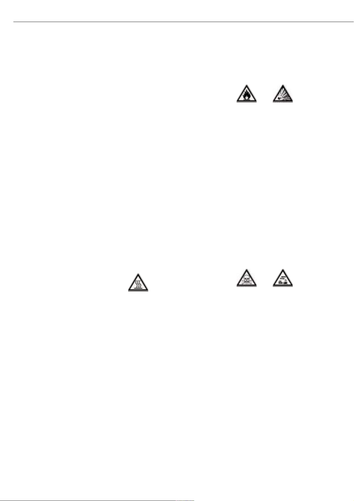
Hazards for persons or equipment
posed by using specific samples:
Fire Explosion
– Flammable or explosive substances
– Substances that contain solvents
– Substances that release flammable
or explosive gases or vapors during the
drying process
In some cases, it is possible to operate
the moisture analyzer in an enclosed
nitrogen atmosphere to prevent the
vapor released during drying from
coming in contact with oxygen in the
surrounding atmosphere. Check on a
case-to-case basis whether this method
can be used, because installation of the
analyzer in too small an enclosed space
can affect its functions (for instance,
through excessive heat build-up within
the analyzer). When in doubt, perform
a risk analysis.
The user shall be liable and responsible
for any damage that arises in connection with this moisture analyzer.
Poisoning Caustic burns
– Substances containing toxic or caustic
or corrosive components: These may
only be dried under a fume hood. The
value for the “lower toxic limit“ in a
work area must not be exceeded.
Corrosion:
– Substances that release aggressive
vapors during the heating process (such
as acids). In this case we recommend
that you work with small sample quantities. Otherwise, vapors can condense
on cold housing parts and cause
corrosion.
The user shall be liable and responsible
for any damage that arises in connection with this moisture analyzer.
4
Warning and Safety Information
Page 5

The moisture analyzer consists of a
heating unit, a weighing system, and a
display and control unit. In addition to
the socket for AC power (mains supply),
it also has an interface port for connecting peripheral devices, such as a PC,
an external printer, etc.
Storage and Shipping Conditions
Allowable storage temperature:
0 ...+40°C (+32°F...+104°F)
Do not expose the moisture analyzer
unnecessarily to extreme temperatures,
moisture, shocks, blows or vibration.
Unpacking the Moisture Analyzer
§ After unpacking the moisture analyzer,
check it immediately for any visible
damage as a result of rough handling
during shipment
$ If any sign of damage is visible, proceed
as directed in the chapter entitled “Care
and Maintenance,” under the section
on “Safety Inspection”
It is a good idea to save the box and all
parts of the packaging until you have
successfully installed your moisture
analyzer. Only the original packaging
provides the best protection for shipment. Before packing your moisture
analyzer, unplug all connected cables
to prevent damage.
Instructions for Recycling
the Packaging
To ensure adequate protection for safe
shipment, your moisture analyzer has
been packaged to the extent necessary
using environmentally friendly materials. After successful installation of the
moisture analyzer, you should return
this packaging for recycling because it is
a valuable source of secondary raw
material. For information on recycling
options, including recycling of old
weighing equipment, contact your
municipal waste disposal center or local
recycling depot.
5
Getting Started
Warranty
Do not miss out on the benefits of our
full warranty. Please contact your local
Sartorius office or dealer for further
information. If available, complete the
warranty registration card, indicating
the date of installation, and return the
card to your Sartorius office or dealer.
Equipment Supplied
The equipment supplied includes the
components listed below:
– Moisture analyzer
– Power cord
– Pan support
– Pan draft shield
– Dust cover for keypad
– 80 disposable aluminum sample pans
– 1 pair of forceps
Installation Instructions
The moisture analyzer is designed to
provide reliable results under normal
ambient conditions in the laboratory
and in industry. When choosing a
location to set up your moisture analyzer, observe the following so that you
will be able to work with added speed
and accuracy:
– Set up the moisture analyzer on a
stable, even surface that is not exposed
to vibrations, and level it using the
four leveling feet
– Avoid placing the analyzer in close
proximity to a heater or otherwise
exposing it to heat or direct sunlight
– Avoid exposing the moisture analyzer to
extreme temperature fluctuations
– Protect the moisture analyzer from
drafts that come from open windows
or doors
– Keep the moisture analyzer protected
from dust, whenever possible
– Protect the moisture analyzer from
aggressive chemical vapors
– Do not expose the analyzer to extreme
moisture
– Make sure to choose a place where
excessive heat cannot build up. Leave
enough space between the moisture
analyzer and materials that are affected
by heat.
Conditioning the Moisture Analyzer
Moisture in the air can condense on the
surfaces of a cold moisture analyzer
whenever it is brought into a substantially warmer place. If you transfer the
moisture analyzer to a warmer area,
make sure to condition it for about
2 hours at room temperature, leaving it
unplugged from AC power. Afterwards,
if you keep the moisture analyzer connected to AC power, the continuous
positive difference in temperature
between the inside of the moisture
analyzer and the outside will practically
rule out the effects of moisture condensation.
Setting up the Moisture Analyzer
§ Position the components listed below in
the order given:
– Dust cover over the keypad
– Pan draft shield
– Pan support; turn to the left or right,
press slightly until it stops and snaps
into place
– Disposable sample pan
Page 6
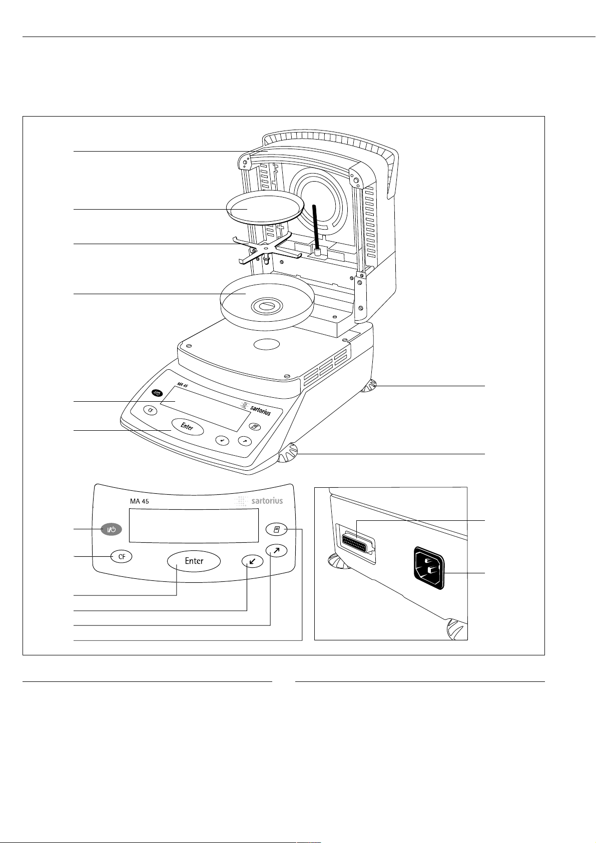
No. Designation Order no. for replacement
1 Hinged cover with heating
element
2 Disposable sample pan 6965542 (80 pcs.)
3 Pan support 69MA0092
4 Pan draft shield 69MA0093
5 Display
6 Keypad
7 On/off key
8 CF key (clear function)
9 ‘Enter’ key (confirm)
No. Designation Order no. for replacement
10 ‘Down/Back’ key
11 ‘Up/Forward’ key
12 Print key
13 Leveling foot
14 Interface port
15 Power socket
Not shown:
Dust cover for keypad 6960MA02
Forceps 69MA0072
6
15
14
7
8
9
10
11
12
1
2
3
4
5
6
13
13
Page 7

§ Check the voltage rating and the plug design
$ The heating unit of the moisture analyzer has been factory-set to 230 V or 115 volts for
technical reasons. The voltage has been set as specified on your order. The voltage setting is
indicated on the manufacturer’s label (see the bottom of the analyzer), for example:
– 230 volts: MA45-...230..
– 115 volts: MA45-...115..
! If they do not match:
Do not operate your moisture analyzer; contact your local Sartorius office or dealer.
Use only
– Original power cords
– Power cords approved by a certified electrician/Sartorius service technician
– If you need to connect an extension cord:
Use only a cable with a protective grounding conductor
§ Connecting the moisture analyzer, rated to Class 1, to AC power (mains supply):
The moisture analyzer must be plugged into a properly installed wall outlet which has a
protective grounding conductor (PE)
Note:
This equipment has been tested and found to comply with the limits for a Class A digital
device, pursuant to Part 15 of the FCC rules. These limits are designed to provide reasonable
protection against harmful interference when the equipment is operated in a commercial
environment. This equipment generates, uses and can radiate radio frequency energy and,
if not installed and used in accordance with the instruction manual, may cause harmful
interference to radio communications. Operation of this equipment in a residential area is
likely to cause harmful interference in which case the user will be required to correct the
interference at his own expense. Changes or modifications not expressly approved by
Sartorius AG could void the user’s authority to operate the equipment.
Safety Precautions
If you use an electrical outlet that does not have a protective grounding conductor,
make sure to have an equivalent protective conductor installed by a certified electrician
as specified in the applicable regulations for installation in your country.
The protective effect must not be negated by using an extension cord without a protective
grounding conductor.
Connecting Electronic Devices (Peripherals)
§ Make absolutely sure to unplug the moisture analyzer from AC power before you connect
or disconnect a peripheral device (printer or PC) to or from the interface port.
Warmup Time
To deliver exact results, the moisture analyzer must warm up for at least 30 minutes after
initial connection to AC power or after a relatively long power outage. Only after this time
will the moisture analyzer have reached the required operating temperature.
7
Connecting the Moisture Analyzer to AC Power
Page 8

Leveling the Moisture Analyzer
Purpose:
– To compensate for unevenness at the place of installation
– This is necessary especially for testing liquid samples that need to be at a uniform level
in the disposable sample pan
Always level the moisture analyzer again any time after it has been moved to a
different location.
§ Extend or retract the front and/or rear leveling feet as needed to adjust the moisture analyzer
Installing the Aluminum Panels (Optional)
! To prevent burns, allow the glass panels to cool sufficiently before removing them
! Do not handle the aluminum panels with oily or greasy fingers
!Do not scratch the aluminum panels; do not use abrasive or corrosive substances to clean
the aluminum panels
§ Remove the 6 screws and remove the panel retainer
§ Remove the glass panels
§ Position the aluminum panels in the retainer
§ Fasten the aluminum panels with the retainer and screws
Turning On the Analyzer; Opening and Closing the Sample Chamber
§ To turn on the analyzer: Press the e key
§ When opening or closing the sample chamber: Do not release the cover until it is in the fully
open or fully closed position
Setting the Language
– See “Setting the Language” in the chapter entitled “Configuring the Moisture Analyzer”
8
Page 9

Operation of the moisture analyzer
follows a standardized “philosophy” which
is described below.
9
Operating Design
y Down/Back
When the operating menu is active:
Shows the next menu item on
the current menu level
When entering alphanumeric characters: Moves the cursor back to
the previous character (see the next
column for character sequence)
x Up/Forward
When the operating menu is active:
Shows the previous menu item on
the current menu level
When entering alphanumeric characters: Moves the cursor forward
to the next character (see the next
column for character sequence)
r Print
Outputs the displayed data or the
active data record via the interface
port to the external printer
Entering Letters, Special Characters
and Numbers:
When the character at the cursor position
is blinking, you can use the y and
x keys to change the character. The
cursor “moves” through the available
characters in the following sequence:
0 1 2 3 4 5 6 7 8 9 . - + / * =
< > ( ) : ? ! $ & % # @ Z Y X W
V U T S R Q P O N M L K J I H G
F E D C B A (Space)
To enter a character: Position the cursor
as desired and press the u key
To confirm a character string: After
entering the last character, press and hold
the u key for at least two seconds
To delete a character: Enter a “space”
Keys
The keys have following functions:
e On/off key
Turns the moisture analyzer on/off.
The moisture analyzer remains in
standby mode
c Clear Function
Cancels application functions, interrupts calibration/adjustment routines
When the operating menu is active:
Closes active submenu and returns
to next higher menu level
u Enter
During moisture analysis: Activates
the selected function (e.g., tare,
start, cancel)
When the operating menu is active:
Confirms the setting or input
displayed
Page 10

Operation
There are two fundamentally different
types of display:
– display for analysis and test functions
– display for menu parameter settings
(e.g., Setup or Program menu)
Analysis and Test Functions
This display is divided into nine
sections.
Example: Moisture Analysis:
Drying Program Info/Status Line:
This line shows the following
information:
– Selected drying program (e.g., P1)
– Configured drying temperature
(e.g., 105
o
C)
– Criterion for end-point recognition
(e.g., Autom.)
– Current temperature
– Elapsed drying time
Busy Symbol:
The J symbol is shown here when
the moisture analyzer is processing a
function activated by pressing a key.
Plus/Minus Sign:
A plus or minus sign (F or H) is shown
here for the weight value or a calculated
value (such as a percentage).
Bar Graph:
The bar graph is shown during moisture
analysis if the “Initial Weight” option in the
drying program is set to On.
The following symbols may be
displayed here:
Bar graph showing interval
markers
- Target value –20%
= Target value
+ Target value +20%
Measured Value:
This section shows the weight or
calculated value.
Unit:
When the weighing system reaches
stability, the weight unit or calculation unit
is displayed here.
Graphic Symbols:
The symbols shown here indicate the
current operating status of the moisture
analyzer. Example:
Drying in progress
Print Symbol:
During the printout of the analysis results
and other data, the following symbol is
shown here:
P Printing
Function Line:
This line indicates the functions that can
be activated by pressing “Enter” (e.g.,
Setup menu, Program menu, “Tare”,
“Start”, or “Cal” (calibration)).
If an error occurs, the resulting error code
or message overwrites this line.
10
P1 105oC Auto.
Drying program/Test status line
Bar graph
Measured value/result
Function line
Plus/minus sign
Busy symbol
Weight
unit
display
Graphic symbol
Print symbol
S
0092
g
PROGRAM
TARESETUP
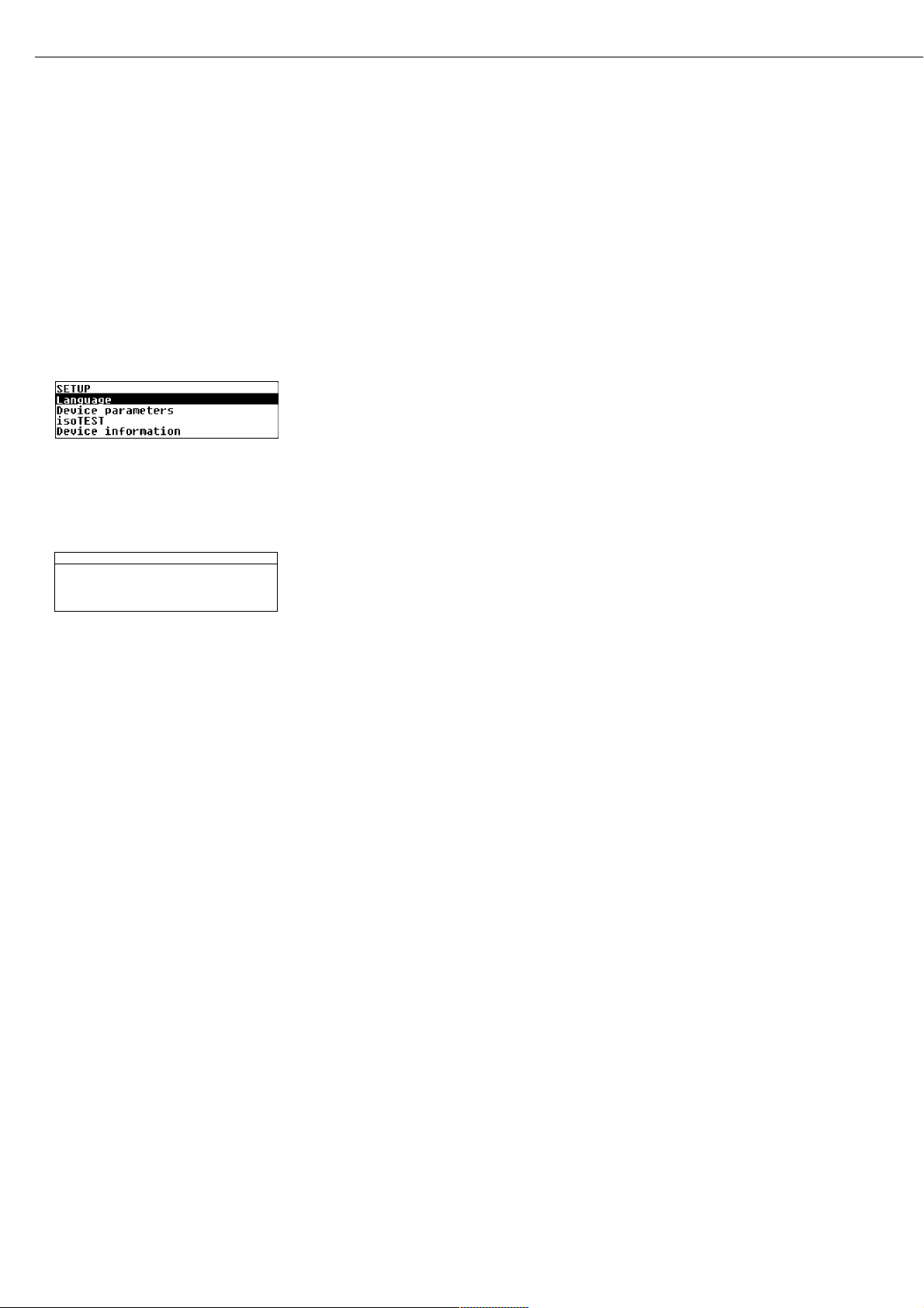
Page 11

Menu Operation
This display is divided into two sections.
Line for Operating Status:
The operating status line indicates the
function of the current screen page. In
the Setup menu, the current menu path
is shown here.
Example for Setup, Language:
Input and Output Window:
This window contains either detailed
information (e.g., on the drying program) or a select list. A selected item is
displayed inversely (white letters on a
black background). You can also enter
letters, numbers, and special characters
in this window when an input field
is active.
Example for Setup, Language:
The following symbol can also appear
the input/output window:
o indicates the currently active menu
setting
SETUP SPRACHE
oDeutsch
English
U.S.-Mode
Français
11
Parameter Settings
The MA45 has an operating menu for
finding and setting parameters. Each
menu has several levels.
Example: Working with the Setup
Menu
First of all, you need to find the menu
item for the parameter you wish to
configure:
§ Press the x and y keys until
SETUP is highlighted, then press u
to confirm
§ Use the x and y keys to move
back and forth between menu items on
a given level
§ To select an item or open a submenu:
Press the u key
Parameter Settings:
§ Press the x and y keys,
repeatedly if needed, until the desired
parameter is highlighted (inverse
display)
§ To select the parameter: Press u
Now you can configure the desired
setting.
To select a parameter setting:
§ Press the x and y keys,
repeatedly if needed, until the desired
setting is highlighted (inverse display)
To enter alphanumeric characters:
§ Press the x and y keys,
repeatedly if needed, until the desired
character is displayed (see page 9 for
details on alphanumeric input) and
press u to confirm
§ Confirm the setting: Press the u key
To go back to the previous (higher)
menu level:
§ Press the c key
Exit the Setup menu: Press the
c key
Data Output
The MA45 is equipped with an interface
port for connecting either
– a printer, or
– a computer
Printer
The data format for output to an
external printer is pre-configured
for generating ISO/GLP-compliant
printouts.
ISO: International Organization
for Standardization
GLP: Good Laboratory Practice
See “Data Output Functions” in the
chapter entitled “Operating the
Moisture Analyzer” for a detailed
description of data output options.
Interface Port
You may choose to connect a computer
rather than a printer to the interface
port.
See “Data Output Functions” in the
chapter entitled “Operating the
Moisture Analyzer” for a detailed
description of data output options.
Line for Operating Status
Input and Output Window
SETUP LANGUAGE
oDeutsch
English
U.S.-Mode
Français
Page 12

Error Codes
If you press a key that has no function,
or which is blocked at a certain point
in an application program, the error is
indicated as follows:
– a double-beep is sounded as an acoustic
signal if the key has no function
– an error message indicates invalid input
– an error code or error message indicates
incorrect operation
The response to operator errors is
identical for all operating modes. See
the chapter entitled “Error Codes”
for detailed explanations of the error
codes and messages.
Saving Data
Storing Parameter Settings
The most recent configurations of
Setup menu parameters and drying
programs are active when you switch on
the moisture analyzer. You also have
the option of restoring the factory
settings at any time (see below).
Protecting Parameter Settings
You can assign passwords to block
access to:
– user-defined drying programs
– the device parameter menu
– isoTEST functions
If no password has been assigned,
anyone can access and change the
Setup > Device menu and the userdefined drying programs without
entering a password.
If you assign a password and then
forget what the word is, you can use
the General Password (see Appendix)
to access these menus.
12
Page 13

Purpose
You can configure your moisture analyzer to meet individual requirements by
entering user data and setting selected
menu parameters in the Setup menu.
The Setup menu is divided into the
following sections:
– Language
– Device parameters
– isoTEST
– Device information
13
Configuring the Moisture Analyzer
Setting the Language
You can choose from 5 languages for
the display:
– German
– English (factory setting)
– U.S. Mode
(English with U.S. date/time format)
– French
– Italian
– Spanish
Example: Selecting the language: “U.S. Mode”
Step Key (or Instruction) Display/Printout
1. Select SETUP in the Function line x or y
and confirm u
2. Confirm Language menu item u
3. Select “U.S. Mode” y
4. Confirm u
5. Exit Setup cc
SETUP
Language
Device parameters
isoTEST
Device information
SETUP LANGUAGE
Deutsch
oEnglish
U.S.-Mode
Français
P1 105oC Auto.
S
0000
g
PROGRAM
TARESETUP
Page 14
Setting the Device Parameters
(DEVICE)
Purpose
Device configuration, i.e., to meet
individual requirements by selecting
predefined menu parameters in the
Setup menu. You can block access to
the menu by assigning a password.
Features
The device parameters are combined in
the following groups:
– Password to the Setup menu
– Interface
– Display contrast
– Acoustic signal
– Factory settings
You can display, enter or change the
following parameters:
Password
– Password for access to the device
parameters and isoTEST functions
in the Setup menu, and to drying
programs in the Program menu
Interface
– SBI operating mode
Simple record of analysis results for PC
or external printer, factory setting for
the YDP03-0CE printer
Format: baud rate, number of data bits,
parity, stop bits, handshake
– xBPI operating mode
Function-oriented interface with transparent data transmission
Network address: enter a number from
0 to 31; factory setting: 0
Display contrast
– Contrast/angle of the display (enter a
number from 0 to 4; factory setting: 2)
Acoustic signal
– Acoustic signal on or off
Factory Settings
Parameters: The factory-set configurations are identified by an “ο” in the list
starting on page 17.
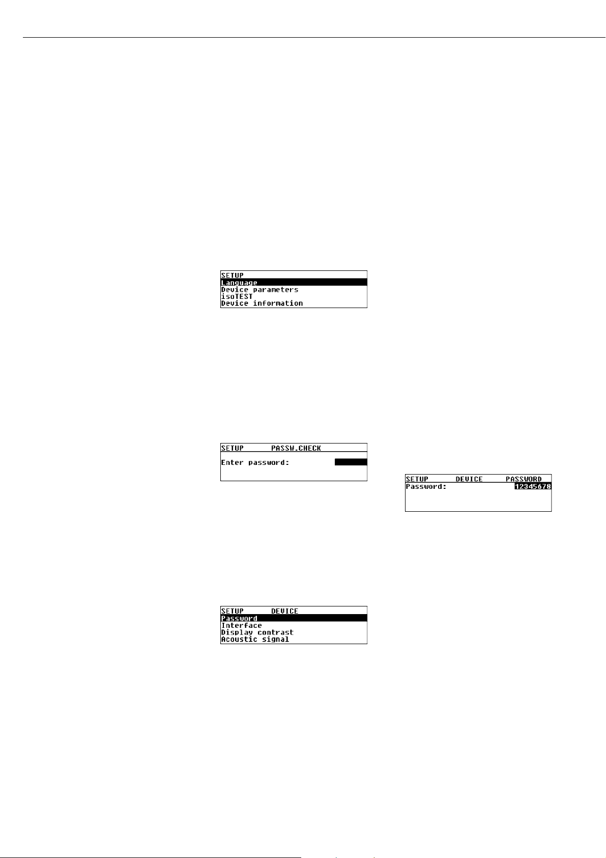
Preparation
Display existing device parameters
§ Select the Setup menu:
Use the x or y key to select
SETUP in the Function line and press
u to confirm
> SETUP is displayed:
§ Select Device parameters: Press the
y key and press u to confirm
If no password has been assigned,
anyone can access “SETUP: Device
parameters” without entering a
password
If a password has been assigned:
> The password prompt is displayed
$ If the Setup menu is protected by a
password: Use the x and y keys
to enter the password (see page 9 for
details) and press u to confirm
§ Confirm the password and display
“Device parameters”:
Press the u key
> Device parameters are displayed:
Entering or Changing the Password
– The password (up to 8 characters)
protects the following functions:
– Setup: Device parameters
– Program: Drying programs
– Setup: isoTEST functions
§ Display Device parameters (see
“Preparation > Display existing device
parameters” above)
§ Write down the password here for easy
reference:
Password = . . . . . . . . . . . . . . . . . . . . . .
If you assign a password and then
forget what it is:
$ Enter the General Password
(see Appendix)
$ Confirm the password and display
device parameters:
Press the u key
> Parameters are displayed (see above)
§ Configuring device parameters:
Select “Password” (if configured) and
confirm: Press the u key
> Password: and any existing password
are displayed:
§ New password: Use the x and y
keys to enter the new password (up to
8 characters) and press u to confirm
If no entry is shown under “Password”,
then no password has been stored
§ To confirm your input:
Press the u key
§ Exit the Setup menu:
Press the c key twice
14
Page 15
Additional Functions
Print out parameter settings:
§ If “Device parameters” are displayed:
Press the r key
> Printout (example)
Lines with more than 20 characters
are truncated
--------------------
SETUP
DEVICE
--------------------
Interface
SBI
Baudrate
1200 baud
Number of data bi
7 data bits
Parity
Odd
Number of stop bi
1 stop bit
Handshake mode
Hardware handshake a
fter 1 char
Display contrast
2
Acoustic signal
On
--------------------
15
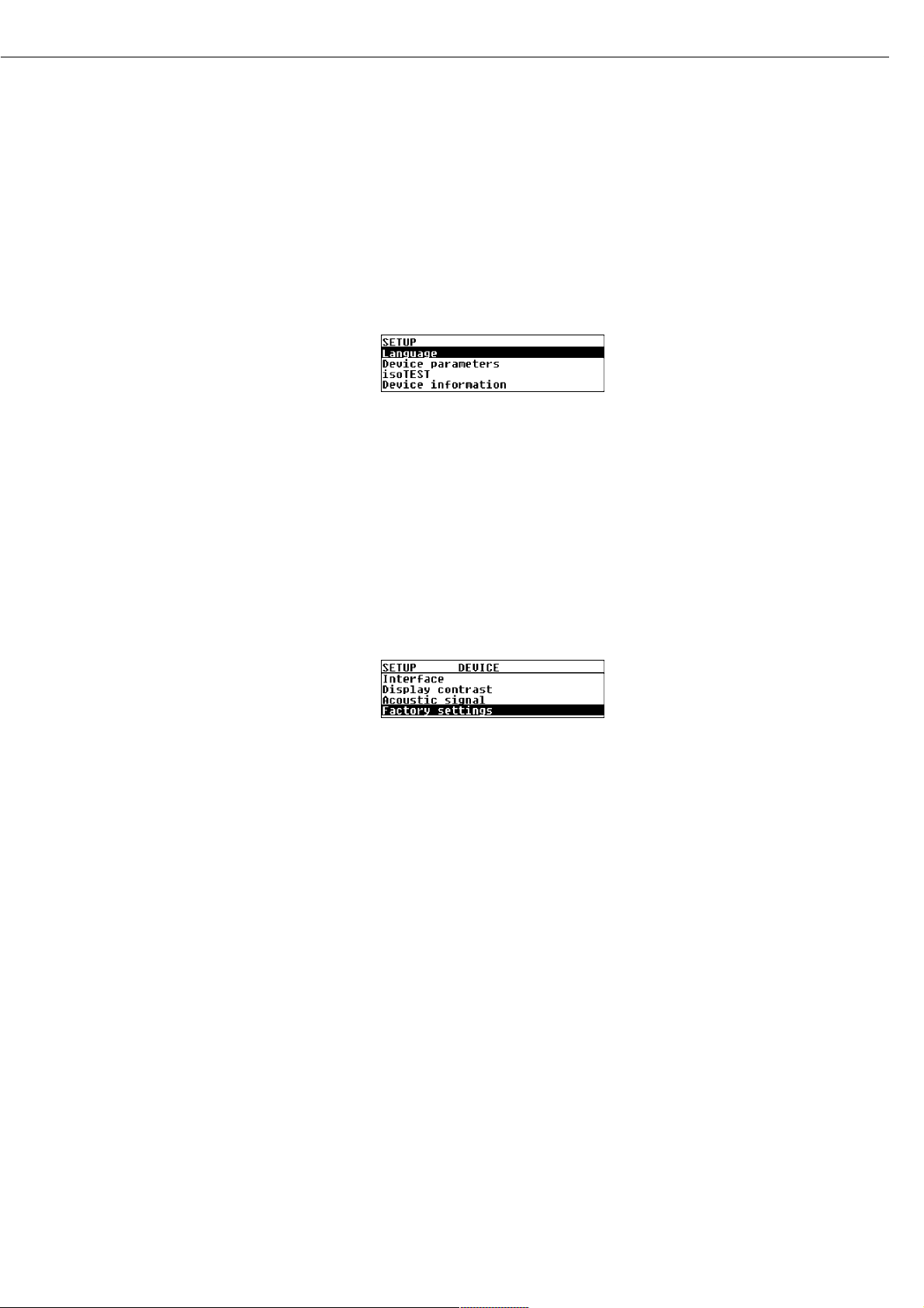
Reset the device parameters to the
factory settings:
§ Select the Setup menu:
Use the x or y key to select
SETUP in the Function line and press
u to confirm
> SETUP is displayed:
§ Select Device parameters:
Press the y key and press u
to confirm
$ If a password has been assigned: enter
the password as described above
§ Confirm the password and display
“Device parameters”:
Press the u key
> Device parameters are displayed
§ Select Factory settings:
Press the y key 4 times
§ Confirm Factory settings:
Press the u key
$ To cancel the “Reset” operation at
this point: Press the c key
§ Select Yes and confirm.
Press the y key and then
press the u key
§ Exit the Setup menu:
Press the c key three times
Page 16

Example:
Set the display contrast to “3”
Step Key (or Instruction) Display/Printout
1. Select SETUP in the Function line x or y
2. Confirm SETUP u
3. Select Device parameters y
4. Confirm Device parameters u
5. Select Display contrast 2 ƒ y
6. Confirm Display contrast u
7. Select setting 3 x or y
(repeatedly, if necessary)
8. Store setting u
9. Exit the Setup “Device parameters” menu c three times
16
P1 105oC Auto.
S
0092
g
PROGRAM
TARESETUP
SETUP DEVICE CONTRAST
0
1
o2
3
SETUP DEVICE CONTRAST
0
1
o2
3
SETUP DEVICE CONTRAST
0
1
2
o3
P1 105oC Auto.
S
0000
g
PROGRAM
TARESETUP
Page 17

Device Parameters (Overview)
ο Factory setting
√ User-defined setting
Setup – Password: empty Enter 8
Device characters max.
parameters
Interface ο SBI Baud rate 150 baud
300 baud
ο 1,200 baud
2,400 baud
4,800 baud
9,600 baud
19,200 baud
Number of data bits ο 7 bit
1
)
8 bit
Parity None
2
)
ο Odd
Even
Number of stop bits ο 1 stop bit
2 stop bits
Handshake Software handshake
mode ο Hardware handshake
1 character after CTS
xBPI Network address: 0 Enter any number from 0 to 31
Display contrast 0
1
ο 2
3
4
Acoustic signal ο On
Off
Factory settings No
Yes
1
) not if parity is set to “None”
2
) only with 8 (not 7) data bits
17
Factory setting
Factory setting
Page 18
Device Information
Purpose
Display of device information
Display Device Information
§ Select the Setup menu:
Use the x or y key to select
SETUP in the Function line and press
u to confirm
> SETUP is displayed:
§ Select Device information:
Press the y key three times and
press u to confirm
> Device information is displayed
§ Exit the Setup menu:
Press the c key twice
§ Print device information:
Press the r key
> Printout (Example)
--------------------
13.08.2001 13:02
Model MA45-000230V
Ser. no. 13206969
Ver. no. 01-43-01
(Operating program version)
ID
------------------SETUP
INFO
-------------------Version no.:
01-43-01
(Operating program version)
W.sys.ver.#:
00-25-03
(Wgh.sys.program version)
Model:
MA45-000230V
Serial no.:
13206969
--------------------
§ Return to Setup menu:
Press the c key
§ Exit the Setup menu:
Press the c key twice
> Previous status is restored
18
SETUP INFO
Versionno.: 01-43-01
W.sys.ver.#: 00-25-03
Model: MA45
Serial no.: 90706913
Page 19
Purpose
The MA45 moisture analyzer can be
used for quick and reliable determination of the moisture content of
materials of liquid, pasty and solid
substances using the thermogravimetric
method.
19
Basics of Moisture Analysis
Material
The moisture of a material is often mistakenly equated with its water content.
In fact, the moisture of a material
includes of all the volatile components
which are given off when the sample is
heated, no matter the kind of material.
Among such volatile substances are:
– water
– fats
– oils
– alcohols
– organic solvents
– flavorings
– products of decomposition
(when a sample is overheated)
There are many methods for determining the moisture content of a substance. Basically, these methods can be
divided into two categories: absolute
and deductive methods.
When absolute methods are used, the
moisture content is directly determined
(for example, as a weight loss registered
during the drying routine). These
methods include oven drying, infrared
drying, and microwave drying. All
three of these methods are thermogravimetric.
When deductive methods are used, the
moisture content is indirectly determined. A physical property related to
the moisture in the substance is measured (e.g., absorption of electromagnetic rays). These methods include
Karl-Fischer titration, infrared spectroscopy, microwave spectroscopy, etc.
Thermogravimetry is the process of
determining the loss of mass that
occurs when a substance is heated. In
this process, the sample is weighed
before and after being heated, and the
difference between the two weights
determined is calculated.
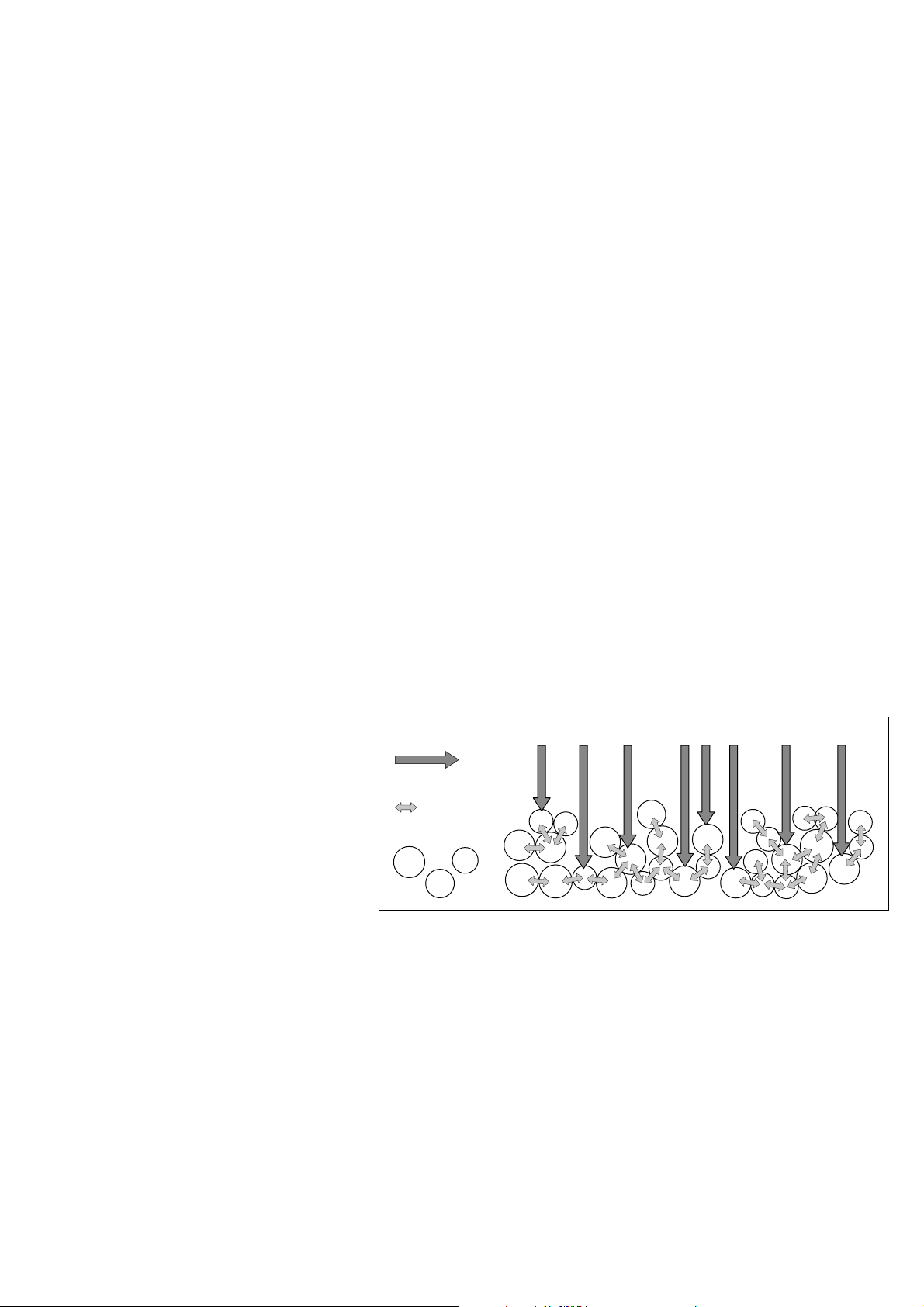
In a conventional drying oven, circulating hot air warms the sample from the
outside toward the inside. Efficiency
is lost during drying because as the
moisture evaporates, it cools the sample
surface.
By contrast, infrared rays (IR rays) penetrate a sample without being impeded.
Having reached the interior of a sample,
they are converted into heat energy,
which stimulates evaporation, thus drying the sample.
IR rays
thermal energy
substance
IR-Strahlung
Wärmeenergie
Substanz
Page 20

A small part of the IR rays is reflected
from the surface of the substance. The
quantity of reflected IR rays depends to
a great extent on whether the substance
is light or dark-colored.
Dark Substance Light Substance
Low Reflection High Reflection
How the rays penetrate the sample
depends on the sample’s degree of
light-transmitting capacity. If the
degree of light-transmitting capacity is
low, the rays can penetrate only the
uppermost layers of the sample. The
heat conductivity of the sample dictates
the degree to which the heat can be
transmitted to the underlying layers.
The higher the conductivity, the faster
and more uniformly the substance is
heated.
The substance should be applied to the
sample pan in a thin, even layer. A
height of approximately 2 – 5 mm for
5 – 15 g substance weight has proved
to be ideal. Otherwise, the sample will
not be dried completely or the analysis
time will be unnecessary extended, a
crust/skin will form on the surface of
the sample or the sample will scorch,
and the analysis results obtained will
not be reproducible, and therefore
cannot be used.
Incorrect Application of a Sample
When preparing a substance for analysis, you should use methods that do not
generate heat so that the sample does
not lose moisture before it is analyzed.
Perform initial analysis of a new substance to test how the IR rays are
absorbed by the sample and converted
into heat. A printout of the intermediate values of the drying process (see
page 25) provides you with this information at an early stage.
Experience has shown that the temperature setting selected for infrared drying
is usually lower than the temperature
setting used when working with a drying oven.
In many cases, the fully automatic shutoff mode will meet your requirements.
If the final result is higher or lower than
expected, try varying the temperature
setting before resorting to a different
shutoff parameter.
When analyzing the samples that lose
their moisture only very slowly or when
operating a cold moisture analyzer,
the fully automatic mode may end the
drying routine too early, if it does not
detect any analyzable progress in the
drying routine under these conditions.
In this case, preheat the moisture analyzer for 2–3 minutes before starting
the drying routine, or select a different
shutoff parameter.
The Sartorius Moisture Analyzer
Applications Guide will provide you
with important information on the
use of your moisture analyzer.
20
Page 21

Preparation
Before drying a sample, you must carry
out the following preparations:
– Adjustment to the available measuring
system (if required)
– Sample preparation
– Setting the drying program parameters
21
Adjustment to an Existing Measuring System
A moisture analysis method often replaces another drying method (e.g., oven drying
method), because it is simple to use and requires shorter analysis time. In this case, you
should adapt this method to that of the moisture analyzer in order to obtain values
comparable to those yielded by your standard reference method.
§ Perform parallel measurements: take a fresh sample and divide it in half
§ Determine the moisture content of the first half using your standard method of analysis
§ Analyze the second half of the sample in the moisture analyzer.
Use the following settings:
– fully automatic mode for the shutoff parameter
– lower temperature settings than for the oven drying method
– temperature setting for organic substances: 80–100°C
– temperature setting for inorganic substances: 140–160°C
$ If the result of the second analysis does not correspond to that of the first:
– first, repeat the analysis using a different temperature setting
– then use the semi-automatic mode for the shutoff parameter (for example,
with a different loss rate per 24 s)
$ Vary the shutoff parameter, if required:
– Increase end-point recognition: set the parameter to 2 mg / 24 s or 1 mg / 24 s
– Decrease end-point recognition: set the parameter to 10 mg / 24 s or 20 mg / 24 s
Page 22

Preparing a Sample
Selecting a Sample
§ Select a representative part of the whole substance as a sample
– a representative number of individual samples for quality control
– samples which indicate a trend are sufficient for in-process control
$ Homogenize the product before a sample is taken, if required, by:
– mixing or stirring,
– taking several samples from different areas of the product, or
– taking several samples at defined intervals
§ Take only one sample at a time for a given analysis and prepare it as quickly as possible.
In this way, it will not lose or gain moisture as a result of the ambient conditions.
$ If you need to analyze several samples at a time, the samples must be sealed in air-tight
containers, in order to ensure that the storage conditions do not alter the state or
condition of the samples:
– Warm or highly volatile substances lose their moisture very quickly.
– If you store the samples in a container, the moisture can condense on the walls
of the container.
– If the container is too big and not filled completely, the sample can exchange its
moisture with the air remaining in the container.
$ Mix the condensed moisture back in with a sample, if necessary.
Preparing a sample
§ When crushing a sample, avoid any contact with heat: heat results in moisture loss.
§ Crush a sample with
– a pestle
– a shredder (see below)
For liquids containing solids, use
– a glass stirrer
– a spoon or
– a magnetic stirrer.
$ Use an appropriately designed tool for shredding a sample.
Using disposable sample pans
§ Use only Sartorius disposable sample pans (inner diameter = 92 mm). Reusing sample
pans leads to poor reproducibility of results for several reasons:
– after cleaning, sample residues can still remain on the pan
– residues from cleaning agents can evaporate during the next moisture analysis
– if scratches and grooves are inflicted during cleaning, the hot, rising air produced
during the drying process acts on these surfaces, resulting in a more pronounced
buoyancy
22
Page 23

23
Applying a Sample to the Sample Pan
§ Apply the sample to the sample pan in a thin, even layer
(height: 2 to 5 mm, weight: 5 to 15 g); otherwise:
– a sample applied unevenly will result in a non-uniform distribution of heat
– a sample will not be dried completely
– the analysis time will be unnecessarily extended
– the sample burns or a crust/ skin forms on its surface as a result of a very thick layer
– the crust makes it difficult or impossible for moisture to escape from the sample during
the drying process
– uncertain and unknown quantity of moisture remains in the sample
§ Apply liquid samples, pasty samples or samples that can melt to a glass fiber filter
(order no. 6906940); you will obtain the following advantages:
– uniform distribution due to the capillary effect
– liquids prevented from beading together and forming drops
– with larger surfaces, the moisture can evaporate faster
– considerably more convenient than the “sea-sand method”
When drying samples containing sugar, a crust or skin can form and seal the surface.
A glass fiber filter is especially helpful in such cases. The moisture can evaporate downwards through the surface of the filter. You can prevent or limit the crust/ skin formation
if you place the glass fiber filter on top of the sample.
§ Cover solid, heat-sensitive samples with a glass fiber filter (order no. 6906940); you will
obtain the following advantages:
– gentle heating, because of the sample surface is shielded from excessive heat
– higher temperature setting can be selected
– uniformity of the sample surface
– fast evaporation of the moisture
– excellent reproducibility for samples containing fat
Avoiding the Formation of Crust/Skin
You can add “solvents” to the sample to prevent the formation of crust/skin during the
analysis runs. The weight of a solvent you apply to the sample will not influence the final
result of an analysis.
§ Once you have closed the sample chamber, open it again within 2 seconds after you hear
a beep tone.
§ Apply a solvent to the sample
§ Close the sample chamber and start the analysis run as usual
Page 24

Setting the Drying Parameters
Purpose
Adapt the moisture analyzer to the special requirements of products.
Parameters can be configured individually for each program.
Drying Parameters (Overview)
ο Factory setting
√ User-defined setting
Program ο P1
memory P2
(PROGRAM) P3 Heating program ο Standard drying Temperature 105°C 40...230°C
MA30 mode Temperature 105°C 40...160°C
1
)
Standby ο Off
temperature
2
) On Temperature 40°C 40...100°C
Initial weight ο Off
On Target 5.0 g 0.2 g...35.0 g
Start analysis With stability
when Enter pressed
ο Without stability
when cover is closed
End of analysis ο Fully automatic
Semi-automatic Loss/24 s 5 mg 1...20 mg
Timer mode Time 15.0 min 0.1...99.9 minutes
Display mode ο Moisture (%L)
Dry weight (%R)
Ratio (%LR)
Residual weight (g)
Residual weight (g/kg)
Print ο Off
intermediate results On Interval 0.1 min 0.1...10.0 minutes
Factory settings No
Yes
1
) Marked in Info/Status line by an asterisk (“*”); e.g. “*105oC”
2
) Not when using the “MA30 mode” heating program
24
Operating the Moisture Analyzer
Factory setting
Factory setting
Factory setting
Page 25
Features
Number of Drying Programs
MA45: 3 programs
Programs are listed according to
program number.
Heating Programs
To perform a moisture analysis of a
substance, you can choose between two
heating programs:
– Standard drying
– MA30 mode
Standard drying:
With the standard program, you need to
enter the final temperature.
If you enter a target temperature of
over 200°C, the moisture analyzer heats
to the target and then adjusts to 200°C
in 5 phases, from the 10th to the 30th
minute.
MA30 Mode:
The moisture analyzer heats as in the
standard mode, but converts to values
corresponding to those in the MA30
(old adjustment disk; 20...200°C –>
20...160°C). This mode is active only
for moisture analysis (before, during
and after drying), but not during heat
adjustment or heating tests.
25
Standby Temperature
– Temperature set to defined value when
the sample chamber is closed
Initial Weight
You can select a weight to be used as a
guide for applying a sample to the analyzer. This value is stored as a target
weight and is not used as a start condition for the drying program. Tolerance
limits of ± 20% are displayed.
Start of Analysis
– With stability after the u key
is pressed:
When START is shown in the Function
line and you press u to confirm, the
initial weight is stored at stability
regardless of whether the cover is open
or closed.
– Without stability after the cover
is closed:
A symbol shown in the graphic symbol
display prompts you to close the cover
once the initial weight condition is met.
The initial weight is stored without
stability as soon as the sample chamber
is closed.
The analysis starts as soon as you
close the cover and a 2-second delay
has elapsed.
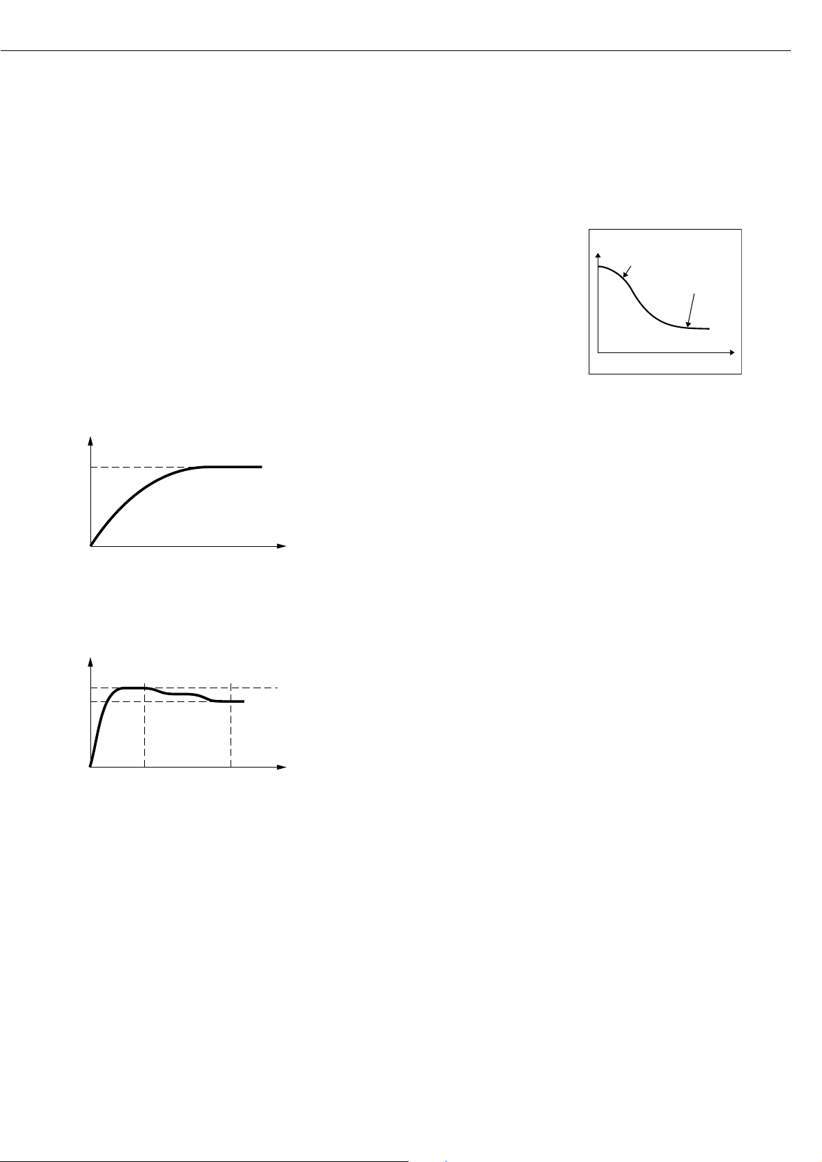
End of Analysis with Shutoff
Parameters
– fully automatic mode
– semi-automatic (absolute)
– timer-mode
Fully Automatic Mode:
The analysis ends as soon as the weight
loss per 24 s is below an automatically
detected threshold.
Semi-automatic, absolute:
The analysis ends as soon as the weight
loss per 24 s is lower than a userdefined threshold (set in milligrams).
Timer Mode:
The analysis ends as soon as the
specified time has elapsed.
Display Mode
The following units can be selected for
displaying analysis results:
– Moisture %L
– Dry weight %R
– Ratio %LR
– Residual weight g
– Residual weight g/kg
Print Intermediate Results
Intermediate results can be printed
either at user-definable time intervals
or by pressing the r key.
Factory Settings
The drying programs can be reset to the
factory settings.
Weight
Moisture
Automatic Shutoff
Time
T [°C]
Standardtrocknung
t [s]
T [°C]
200°C
Standardtrocknung
10
30 t [min]
Page 26

Printout of the Analysis Parameters
§ When the desired program is displayed:
Press the r key
> Parameters are printed (see example
on the right)
Lines with more than 20 characters
are truncated.
Additional Functions
The following functions are available in
the program memory:
– Display programs
– Change program settings
– Save changes
--------------------
13.08.2001 13:06
Model MA45-000230V
Ser. no. 13206969
Ver. no. 01-43-01
ID
--------------------
PROGRAM
P1
--------------------
Heating program
Standard drying
Temperature:
105 ’C
Standby temperatur
Off
Bar graph for weig
Activated
Target wght:
5.0 g
Start analysis
Without stability, a
fter close
End of analysis
Automatic
Display mode
Moisture (%L)
Print intermediate
Off
--------------------
26
Page 27

Example: Standard Drying with Fully Automatic Shutoff Mode
The moisture content of 2 g of corn starch is to be analyzed. The sample can scorch if overheated, but it is not particularly heat sensitive.
The analysis is to be ended automatically as soon as a constant weight is reached.
Settings (changes in the factory settings required for this example):
Program number: 1
Final temperature: 130°C
Start of analysis: With stability after “Enter” key is pressed
End of analysis: automatic (factory setting)
Part A: Configuring the Drying Parameters
Step Key (or Instruction) Display/Printout
1. Turn on the moisture analyzer e Sartorius logo is displayed
Self-test runs
2. Select the PROGRAM function y or x
3. Confirm the PROGRAM function u
4. Select P1 program u
5. Select Heating program u
6. Select Standard drying u
7. Enter the temperature: 130 u
3 ƒ x
u
5 ƒ y
u
27
P1 105oC Auto.
S
0092
g
PROGRAM
TARESETUP
Page 28

Step Key (or Instruction) Display/Printout
8. Confirm the temperature u
9. Select the Initial weight c
parameter 2 ƒ y
10. Confirm the Initial weight u
parameter
11. Select the On setting and y
confirm u
12. Enter the target weight 2.0 3 ƒ x
u
13. Confirm the target weight u
14. Select the Start of analysis c
parameter y
15. Confirm the Start of analysis u
parameter
16. Select the With stability,
after ENTER key setting x
and confirm u
17. Exit the PROGRAM function 3 ƒ c
28
Page 29

Part B: Performing the Analysis
Step Key (or Instruction) Display/Printout
1. Turn on the moisture analyzer e Sartorius logo is displayed
Self-test runs
2. Prepare the sample: not necessary
for corn starch
3. Open the sample chamber and
position a new sample pan
4. Tare the sample pan:
Select the TARE function y or x as needed
and confirm u
5. Spread approx. 2 g of corn
starch uniformly on the sample pan
Close the sample chamber
6. Start the drying program u
After 2 seconds’ delay
the header for the
moisture analysis is printed
(see next page)
29
P1 130oC Auto.
S
P1 130oC Auto.
S
P1 130oC Auto.
S
P1 130oC Auto. Delay 2sec
S
0092
0002
PROGRAMM
2036
PROGRAMM
2036
PROGRAMM
g
PROGRAM
g
g
g
TARESETUP
TARASETUP
STARTSETUP
TARASETUP
P1 130oC Auto. Verzög. 2sec
S
2036
PROGRAMM
g
TARASETUP
S
Page 30

Step Key (or Instruction) Display/Printout
--------------------
13.08.2001 16:01
Model MA45-000230V
Ser. no. 13206969
Ver. no. 01-43-01
ID
-------------------Prg. 1
Heating STANDARD
Fin. temp. 130 ’C
Stdby temp. OFF
Start W/STABIL.
End AUTOMATIC
IniWt + 2.036 g
The current moisture loss is displayed
after the data is printed.
The drying program shuts off
automatically once no further
weight loss is detected (in this
example, after 5.2 minutes)
Then the footer of the analysis -------------------record is printed FinWt + 1.814 g
5.2+ 18.90 %L
Name:
--------------------
30
P1 130oC Auto. 37oC 0.8min
S
P1 130oC Auto. 128oC 5.2min
S
005
PROGRAMM
1890
PROGRAMM
%L
%L
CANCELSETUP
NEXTSETUP
Page 31

The following functions are available
in the SETUP menu, under the isoTEST
menu item:
– Weighing system:
– Calibration/adjustment
– Weighing only
– Hardware tests
– Test interfaces
– Heater test
When the sample pan and the pan support are removed from the sample
chamber, you have access to the following functions:
– Heater adjustment
– 2-point temperature adjustment
– 1-point temperature adjustment
31
“isoTEST” Calibration/Adjustment Functions
Heater Adjustment
Using 1-point and 2-point temperature
adjustment and the YTM03MA temperature adjustment set (see “Accessories”)
you can calibrate and adjust temperature settings of the drying unit.
Weighing System Settings
Calibration, Adjustment
Purpose
Calibration is the determination of the
difference between the weight readout
and the true weight (mass) of a sample.
Calibration does not entail making any
changes within the weighing system.
Adjustment is the correction of the
difference between the measured value
displayed and the true weight (mass)
of a sample, or the reduction of the
difference to an allowable level within
maximum permissible error limits.
Features
Calibration is performed externally
with a pre-set weight value of 30 g (see
“Accessories”, order no. YSS43).
You can have calibration and adjustment results documented as a ISO/GLPcompliant printout; see the next page.
Page 32

External Calibration/ Adjustment with a Factory-Defined Weight
Externally calibrate and adjust the weighing system using a 30-g calibration weight
Step Key (or Instruction) Display/Printout
1. Select SETUP in the Function line x or y
2. Confirm SETUP u
3. Select isoTEST 2 ƒ y
4. Confirm isoTEST u
5. Confirm Weighing system settings u
6. Confirm Calibration/adjustment u
7. Unload and tare the weighing system u
8. Select the CAL. function y
9. Start calibration u
32
P1 105oC Auto.
S
0092
g
PROGRAM
TARESETUP
WGH.SYS CAL./ADJ.Verzög. 2sec
S
WGH.SYS CAL./ADJ.Verzög. 2sec
S
WGH.SYS CAL./ADJ.Verzög. 2sec
S
WGH.SYS CAL./ADJ.Verzög. 2sec
J
S
0092
0000
0000
0000
CAL.
CAL.
CAL.
KAL.
g
TAREEND
g
TAREEND
g
TAREEND
g
TARAENDE
Page 33
Step Key (or Instruction) Display/Printout
The weighing system is prepared
for the calibration procedure
When the system is ready, the display shows
10. Place the weight on the weighing system Apply 30-g calibration
(in this example, 30.000 g) weight
Minus sign: weight too low
Plus sign: weight too high
No sign: weight ok
At the end of calibration,
the display shows
11. If no adjustment is required, y
select END in the function line u
and confirm --------------------
13.08.2001 16:15 *)
Model MA45-000230V
*) Date and time shown only when Ser. no. 99992581
using the YDP02 or YDP03 printer Ver. no. 01-43-01
from Sartorius ID
-------------------External calibration
W-ID
Nom. + 30.000 g
Diff. - 0.002 g
--------------------
13.08.2001 16:16 *)
Name:
--------------------
12. If necessary, adjust the u
weighing system
At the end of adjustment,
the display shows
and a report is printed (see next page)
33
WGH.SYS CAL./ADJ.Verzög. 2sec
D
30000
PROGRAMM
WGH.SYS CAL./ADJ.Verzög. 2sec
D
30000
PROGRAMM
WGH.SYS CAL./ADJ.Verzög. 2sec
D
0002
END
g
TARASETUP
g
TARASETUP
g
ADJUSTSETUP
WGH.SYS CAL./ADJ.Verzög. 2sec
D
WGH.SYS CAL./ADJ.Verzög. 2sec
S
0002
30000
ENDE
CAL.
g
JUST.SETUP
g
TAREEND
Page 34

Step Key (or Instruction) Display/Printout
Printout following adjustment: --------------------
13.08.2001 16:15 *)
Model MA45-000230V
*) Date and time shown only when Ser. no. 13206969
using the YDP02 or YDP03 printer Ver. no. 01-43-01
from Sartorius ID
-------------------External calibration
W-ID
Nom. + 30.000 g
Diff. - 0.002 g
External adjustment
completed
Diff. 0.000 g
--------------------
13.08.2001 16:16 *)
Name:
--------------------
13. Unload the weighing system
34
Page 35

Hardware Tests
Purpose
Hardware tests are performed to check
whether the system communication
with internal and external devices
functions properly. These tests are not
elementary hardware tests.
35
The following device elements can
be tested:
– SBI communication
– Heater
Activating Hardware Tests
Step Key (or Instruction) Display/Printout
1. Select SETUP in the Function line x or y
and confirm u
Select isoTEST and confirm 2 ƒ y
u
3. Select Hardware Tests and y
confirm u
Page 36
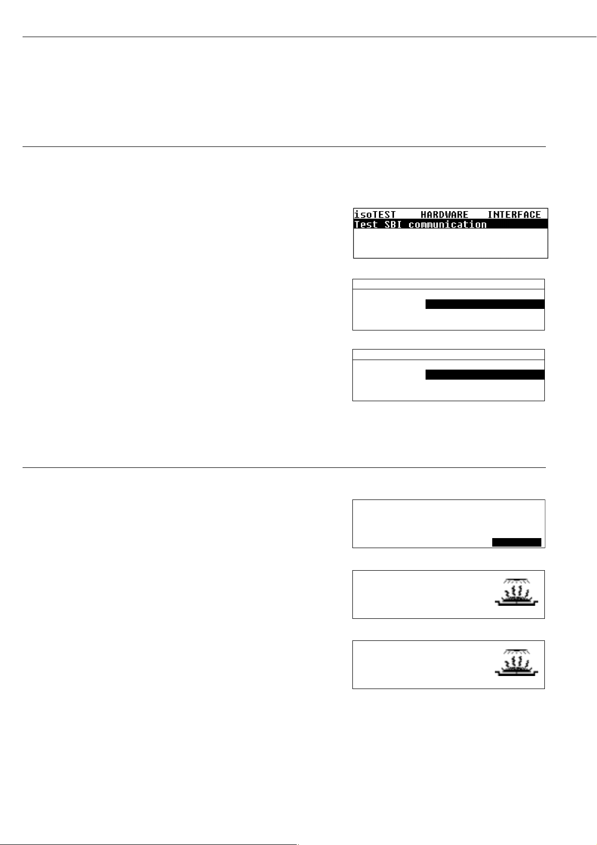
Testing SBI Communication
Step Key (or Instruction) Display/Printout
1. Prepare the test connector for the RS-232 port Connect TƒD (pin 2) with
(see “Pin Assignment Chart”) RƒD (pin 3)
2. Select “Hardware tests” see above
3. Select “Test interfaces” function u
and confirm
4. Confirm “SBI communication u
test” function
At the end of the test, the result
is displayed: Test error
or: Test OK (in this case, Test error)
(the test is repeated continuously)
5. Exit “Test SBI communication” 2 ƒ c
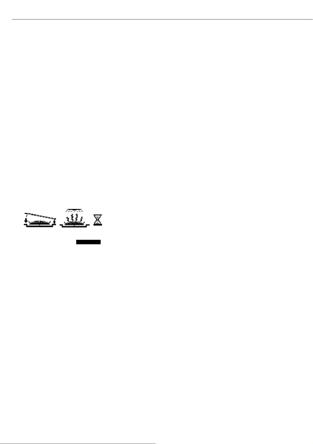
Testing the Heater
Step Key (or Instruction) Display/Printout
1. Select “Hardware tests” see the previous page
2. Select “Heater test” y
and confirm u
3. Start the heater test:
Select the START function u
After initialization, the current
temperature (in this case: 123°C)
and test time (in this case: 1.5 min)
are displayed
If the sample chamber is opened,
the test stops until the sample
chamber is closed again.
After a brief time interval, the device
reaches the nominal temperature.
4. Exit the heater test c
36
HARDWARE INTERFACE SBI
Result: Test Fehler
HARDWARE INTERFACE SBI
Result: Test error
HEATER TST 160oC Verzög. 2sec
S
25
END
o
C
STARTSETUP
o
C
o
C
o
C 1.5min
o
C 11.2min
HEATER TST 160oC160
S
HEATER TST 160oC160
S
123
ENDE
160
ENDE
STARTSETUP
STARTSETUP
Page 37

P1
105
o
C
Auto.
85
o
C 5.4min
HEATER TEST 160
o
C
S
37
Data Output
There are three options for data output:
– Output to the moisture analyzer
– Output to an external printer (YDP02-0CE or YDP03-0CE)
– Output to a peripheral device (e.g., a computer) via the interface port
Output to the Moisture Analyzer Display
(Weights and Calculated Values)
The display is divided into 9 sections. Information about the weighing system, the
application being used and the sample weighed is output in the following sections:
– Drying program/Test status line
– Print symbol
– Bar graph
– Busy symbol
– Plus/minus sign
– Measured value/result
– Weight unit display
– Graphic symbol
– Function line
Drying Program/Test Status
This line shows information on the drying program:
– Program number
– Temperature data
– Shutoff parameter
– Current temperature and elapsed time
– Active test function with parameters
Print Symbol
The print symbol is shown in this section when the r key is pressed or at the start
and end of moisture analysis.
Bar Graph (Overview Display)
The bar graph shows the target weight with tolerance values (–20%, +20%).
The bar graph is displayed if you have selected ON for the “Initial weight” parameter
in the drying program.
Drying program/Test status line
Bar graph
Measured value/result
Function line
Plus/minus sign
Busy symbol
Weight
unit
display
Graphic symbol
Print symbol
Page 38
J
S D
5234
17.23
g
o
C
%L
Busy Symbol
The “Busy” symbol is shown here when the moisture analyzer is processing a function
activated by pressing a key.
Plus/Minus Sign
Any plus or minus sign required for a displayed value is shown here.
Measured Value/Result
This line shows:
– the current weight unit
– calculated values (e.g., % moisture)
Weight Unit Display
This section shows:
– the current weight unit (e.g., g)
– the drying temperature unit
– the unit for calculated values (e.g., % moisture)
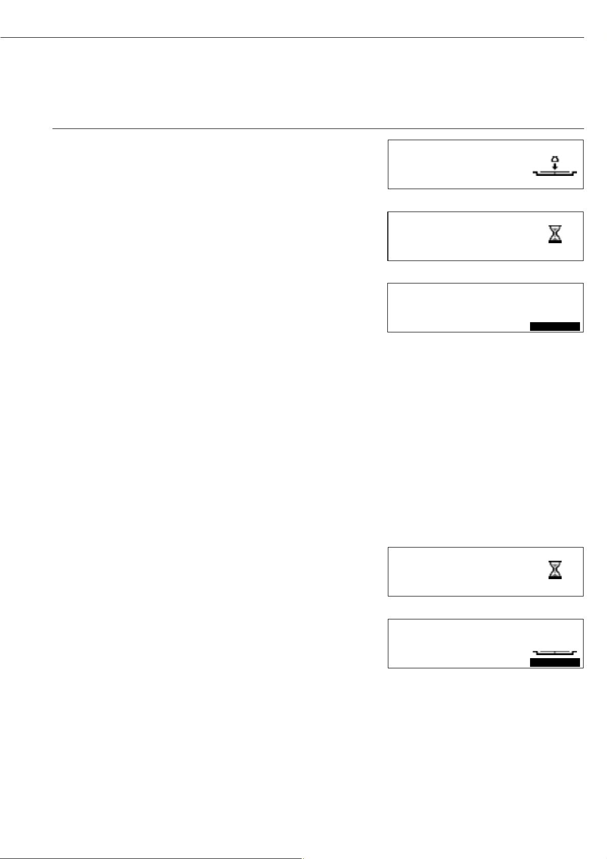
Graphic Symbols
There are a number of different graphic symbols that can be displayed here; for example,
to prompt the next user action (“Close cover”), to indicate the current function (sample
pan with evaporating moisture) or to show that the current internal operation will take
some time (hourglass).
Function Line
This line indicates the functions that can be activated by pressing “Enter” (e.g., Setup
menu, Program menu, “Tare”, “Start”, or “Cal” (calibration)).
If an error occurs, the resulting error code or message overwrites this line.
38
PROGRAM TARESETUP
Page 39

Purpose
The moisture analyzer has an interface
port for connecting an external printer
or computer (or other peripheral device).
External Printer
You can use an external printer to
generate printouts and to document
settings.
Computer
Analyses and calculated values can be
transmitted to a computer for further
evaluation and recording.
!Warning When Using Pre-wired
RS-232 Connecting Cables!
RS-232 cables purchased from other
manufacturers often have incorrect pin
assignments for use with Sartorius
weighing systems! Be sure to check the
pin assignments against the chart below
before connecting the cable, and
disconnect any lines marked “Internally
Connected” (e.g., pin 6). Failure to
do so may damage or even completely
ruin your weighing system and/or
peripheral device.
39
Available Features
Type of interface: Serial interface
Interface operating mode: Full duplex
Standard: RS-232
Transmission rates: 150; 300; 600; 1,200; 2,400; 4,800; 9,600; 19,200 baud
Number of data bits 7, 8 bit
Parity: None, odd, even
Number of stop bits: 1 or 2 stop bits
Handshake mode: Software, hardware 1 character
Operating mode: SBI, xBPI 1)
Network address2): 0, 1, 2, [...], 30, 31
Data output format with SBI: 20 characters + CR LF
1
) xBPI operating mode: 9600 baud, 8 bits, odd parity, 1 stop bit
2
) Network address is valid only in the xBPI mode
Factory Settings for the SBI Operating Mode Parameters:
Transmission rate: 1,200 baud
Number of data bits 7 bits
Parity: Odd
Stop bits: 1 stop bit
Handshake: Hardware 1 character
Operating mode: SBI
Preparation
§ See pages 42 and 43 for the pin assignment chart and cabling diagram.
Interface Port
Page 40

Data Output Format
You can output the values, displayed
in the corresponding line for moisture
analysis values, and the weight unit
with or without a data ID code.
Example: With Data ID code
N + 3.4253 g
20 characters per line are output.
Data Input Format
If you have a computer connected to
the interface port on the moisture
analyzer, you can send the commands
“Esc P CR LF” to generate a printout.
Output Format with 20 Characters + CR LF
12345678910111213141516171819202122
IIIIII+*DDDDDDDD * UUUCRLF
*****– ........ ***
* ********
I: ID code character U: Unit symbol
*: Space CR: Carriage return
D: Digit or letter LF: Line feed
Error Codes
12345678910111213141516171819202122
Stat*****ERR*###****CRLF
*: Space # # #: Error code number
H: Overload
L: Underload
40
Page 41

Synchronization
During data communication between
the moisture analyzer and an on-line
device (computer), messages consisting
of ASCII characters are transmitted via
the interface. For error-free data communication, the parameters for baud
rate, parity, handshake mode and
character format must be the same for
both units.
You can adapt your moisture analyzer
by setting corresponding parameters in
the Setup menu.
If you do not connect a peripheral
device to the analyzer’s interface port,
this will not generate an error message.
41
Handshake
The moisture analyzer SBI interface
(Sartorius Balance Interface) has
transmit and receive buffers. You can
define the handshake parameter in
the Setup menu:
– Hardware handshake (CTS/DTR)
– Software handshake (XON, XOFF)
Hardware Handshake
With a hardware handshake, 1 more
character can be transmitted after CTS
(“clear to send”).
Software Handshake
The software handshake is controlled
via XON and XOFF. When a device is
switched on, XON must be transmitted
to enable any connected device to
communicate.
When the software handshake is
configured in the Setup menu, the
hardware handshake becomes active
after the software handshake.
The data transmission sequence
is as follows:
Moisture
__
byte __> Computer
analyzer
__
byte __> (receiving
(transmitting
__
byte __> device)
device)
__
byte __>
<__XOFF
__
__
byte __>
__
byte __>
…
(Pause)
…
<–– XON ––
__
byte __>
__
byte __>
__
byte __>
__
byte __>
Transmitting Device:
Once XOFF has been received, it prevents further transmission of characters.
When XON is received, it re-enables
the transmitting device to send data.
Receiving Device:
To prevent too many control commands
from being received at one time, XON
is not transmitted until the buffer is
almost empty.
Activating Data Output
You can define the data output parameter so that output is activated either
when a print command is received, or
automatically and synchronously with
the analyzer display.
Data Output by Print Command
The print command can be transmitted
by pressing r or by sending a
software command (Esc P).
Page 42

Female Interface Connector:
25-position D-Submini (DB25S) with
screw lock hardware for cable gland
Male Connector Used:
(please use connectors with the
same specifications):
25-pin D-Submini (DB25S) with
shielded cable clamp assembly (Amp
type 826 985-1C) and fastening screws
(Amp type 164 868-1)
Pin Assignment Chart:
Pin 1: Signal ground
Pin 2: Data output (TƒD)
Pin 3: Data input (RƒD)
Pin 4: Signal return (TƒD/RƒD)
Pin 5: Clear to send (CTS)
Pin 6: Internally connected
Pin 7: Internal ground
Pin 8: Internal ground
Pin 9: Reset _ In*)
Pin 10: –12 V
Pin 11: +12 V
Pin 12: Reset _ Out*)
Pin 13: + 5 V
Pin 14: Internal ground
Pin 15: Internally connected
Pin 16: Internally connected
Pin 17: Internally connected
Pin 18: Internally connected
Pin 19: Internally connected
Pin 20: Data terminal ready (DTR)
Pin 21: Supply voltage ground “COM”
Pin 22: Not connected
Pin 23: Not connected
Pin 24: +10 V
Pin 25: +5 V
*) = Hardware restart
42
Pin Assignment Chart
Page 43

– Diagram for interfacing a computer or other peripheral device to the moisture analyzer using the RS-232/V24 standard and cables
up to 15 m (50 ft.) long
V24
Moisture analyzer Peripheral device
43
Cabling Diagram
+
–
–
+
3
4
5
2
20
14
7
PC PC
25-pin or 9-pin
23
20 4
32
58
66
75
3
5
2
20
Type of cable: AWG 24 specification
Page 44

Error codes are displayed in the main display or text line for 2 seconds.
The program then returns automatically to the previous status.
Display Cause Solution
No segments appear on the display No AC power is available Check the AC power supply
The power cord is not plugged in Plug in the power cord
Fuses are defective Replace the fuses
H The load exceeds the weighing capacity Unload the pan support
L or ERR 54 The pan support is not in place Place the pan support
on the weighing system
ERR 01 Data output not compatible with Change the configuration in
> Display range output format the Setup menu
ERR 02 Calibration/adjustment condition not met, e.g., Calibrate only when zero is displayed
Cal. n. possible – not tared Press the TARE function key
– the pan support is loaded Unload the moisture analyzer
ERR 03 Calibration/adjustment could not Allow the moisture analyzer to warm up
Cal/adj. interrupt be completed within a certain time again and repeat the adjustment process
ERR 30 Interface port for printer output Have the port setting changed
Print fct. blocked is blocked by Sartorius Customer Service
ERR 31 External device not ready to send Transmit XON, then CTS
Print fct. blocked (interface handshake interrupted; XOFF, CTS)
ERR 53 No temperature compensation Contact the Sartorius Service Center
No meas. value
ERR 101 Key is stuck Release key
Key pressed when switching on or contact your local
the moisture analyzer Sartorius Service Center
“Checkerboard” pattern displayed u key was pressed when turning
continuously on the moisture analyzer, or is stuck
ERR 320 Operating program memory is wrong Contact your local
Sartorius Service Center
ERR 340 Operating parameter (EEPROM) Contact your local
is wrong Sartorius Service Center
ERR 342 Operating parameter (EEPROM) is Contact your local
wrong except for adjustment parameters Sartorius Service Center
NO WP Weighing system is defective Contact your local
Sartorius Service Center
blocked Function blocked None
xxxxx too low Input wrong (with any Follow the instructions
xxxxx too high application program), e.g., for the application programs
alphabetic input not allowed
Troubleshooting: see next page
44
Error Codes
Page 45

Problem Cause Solution
What can I do if... The selected temperature is too high – Reduce the temperature
and the sample oxidizes – Put a glass fiber filter on top
of the sample
Sample boils or scorches – Reduce the sample quantity
and the splashes continuously or apply the sample more evenly
change the sample weight – Select a semi-automatic shutoff
parameter or select the timer mode
Analysis time is too long – Increase the temperature
– Reduce the sample quantity
– Preheat the unit by running it for 2 or
3 minutes with an empty sample pan
Sample loses weight – Remove the sample pan and apply
before it is analyzed the sample outside the sample chamber
Sample is liquid or pasty – Use a glass fiber filter
Sample contains too little moisture – Increase the sample quantity
Insufficient heat output – Clean the protective glass or
temperature sensor
Place of installation exposed to – Change the place of installation
interfering factors (vibration, etc.)
If any other errors occur, please contact your local Sartorius Service Center
45
Page 46

Service
Regular servicing by a Sartorius technician will extend the service life of your
moisture analyzer and ensure its continued weighing accuracy. Sartorius can
offer you service contracts, with your
choice of regular maintenance intervals
ranging from 1 month to 2 years.
The frequency of the maintenance
intervals depends on operating conditions and user tolerance requirements.
Repairs
Repair work must be performed by
trained service technicians. Any
attempt by untrained persons to perform repairs may lead to hazards
for the user.
Cleaning
! Make sure that no dust or liquid enters
the moisture analyzer housing
! Do not use any aggressive cleaning
agents (solvents, abrasive cleaning
agents, etc.); clean the moisture analyzer using a piece of cloth which has been
wet with a mild detergent (soap) only
§ Unplug the power cord from the wall
outlet (mains supply)
If you have a cable connected to the
interface, unplug it from the moisture
analyzer
$ The pan draft shield and the pan
support can be removed for cleaning
§ Carefully remove any sample residue/
spilled powder using a brush or a handheld vacuum cleaner
§ After cleaning, wipe down the analyzer
with a soft, dry cloth
Cleaning the Heating Unit and
Temperature Sensor
§ Open the hinged cover
! Danger: The terminals of the heating
unit are under live current
§ To disconnect from AC power,
unplug the power cord from the wall
outlet (mains).
If you have a cable connected to the
interface port, disconnect it from the
moisture analyzer
§ Carefully remove any residue from the
temperature sensor
§ Use a soft-bristled brush or a commer-
cially available cleaning agent for
glassware to clean the ceramic heating
element
46
Care and Maintenance
Page 47

Safety Inspection
If there is any indication that safe
operation of the moisture analyzer is no
longer warranted:
§ Turn off the power and disconnect
the equipment from the wall outlet
immediately
> Lock the equipment in a secure place
to ensure that it cannot be used for the
time being
Safe operation of the moisture analyzer
is no longer ensured when:
– there is visible damage to the moisture
analyzer or power cable
– the moisture analyzer no longer
functions properly
– the moisture analyzer has been stored
for a relatively long period under
unfavorable conditions
– the moisture analyzer has been exposed
to rough handling during shipment
In this case, notify your nearest
Sartorius Service Center. Maintenance
and repair work may be performed
only by service technicians who are
authorized by Sartorius and who:
– have access to the required mainte-
nance manuals
– have attended the relevant service
training courses
We recommend that the moisture
analyzer be inspected according
to the following checklist by a qualified
Sartorius service technician:
– Resistance of the protective grounding
conductor < 0.2 ohm measured with a
commercially available multimeter
– Insulation resistance > 2 megohms
measured with a constant voltage of at
least 500 volts at a 500 kohm load
The duration and number of measurements should be determined by a
qualified Sartorius service technician
according to the particular ambient and
operating conditions. However, such
inspection must be performed at least
once a year.
47
Page 48

Specifications
Model MA45
Dryer functions:
Heating element Ceramic IR heater
Temperature range 40 – 230°C
Temperature increments adjustable in 1°C increments
Temperature adjustment with YTM03MA temperature adjustment set
Weighing Functions:
Weighing capacity 45 g
Readability 1 mg, 0.01% moisture content
Repeatability, average (%) sample weight 1–5 g: 0.2%
sample weight 5 g: 0.05%
External calibration weight 30 g (± 0.3 mg)
(with an accuracy of at least...)
Sample pan dimensions ‡ 90 mm
Drying parameters:
Drying programs Standard; MA30 mode
Drying time 0.1 to 99.9 minutes
Number of programs 3
Shutoff criteria Fully automatic, semi-autom. (1 – 20 mg/24 s),
timer mode (1 ƒ 99.9 Min.)
Display of analysis results Moisture, dry weight, RATIO, residual weight (g or g/kg)
Minimum sample weight 0.100 g
Analyzer (hardware):
Dimensions (W ƒ D ƒ H) 213 ƒ 320 ƒ 181 mm
Net weight, approx. 5.1 kg
Voltage 230 V or 115 V (depending on model variant), –15% ... +10%
Frequency 48 – 60 Hz
Fuses 2 (neutral conductor/phase), 6.3 AT, 5 ƒ 20 mm (internal)
Operating temperature range +10 ... +30°C
Power consumption 700 VA max.
Built-in interface RS-232C
Format: 7 bit ASCII, 1 start bit, 1 or 2 stop bits
Parity: Odd or even
Transmission rates: 150 to 19,200 baud
Handshake: Software or hardware
48
Overview
Page 49

49
Accessories (Options)
Product Order No.
External printer YDP03-0CE
Printer expendables:
– 5 paper rolls 69 06937
– ink ribbon 69 06918
Temperature adjustment set YTM03MA
Exchangeable panels for drying unit (aluminum) YDS04MA
Carrying case YDB05MA
Software for recording moisture analysis values YMW02MA
Expendables:
– 80 disposable sample pans, ‡ 90 mm (aluminum) 69 65542
– 80 glass fiber filters (for liquid samples) 69 06940
Interface cable (RS-232/25-pin) 69 57312
Calibration weight, 30 g (± 0.3 mg) YSS43
Standard Operating Procedure (SOP)YSL02A
For Working with a Moisture Analyzer
(For Quality Assurance Documentation)
Spare Parts
Dust cover for keypad 6960MA02
Forceps 69MA0072
Other spare parts can be ordered directly through your local
Sartorius Service.
Page 50

The moisture analyzer complies with the
following EC Directives and European
Standards:
Council Directive 89/336/EEC
“Electromagnetic Compatibility
(EMC)”
Applicable European Standards:
Limitation of emissions:
In accordance with product standard
EN 61326-1 Kl.B (residential area)
Defined immunity to interference:
In accordance with product standard
EN 61326-1 (industrial area)
Important Note:
The operator shall be responsible for
any modifications to Sartorius equipment and must check and, if necessary,
correct these modifications. On request,
Sartorius will provide information on
the minimum operating specifications
(in accordance with the Standards listed
above for defined immunity to interference).
73/23/EEC “Electrical equipment
designed for use within certain
voltage limits”
Applicable European Standards:
EN 563
Safety of machinery – temperatures
of touchable surfaces
EN 60950
Safety of information technology
equipment including electrical business
equipment
EN 61010
Safety requirements for electrical
equipment for measurement, control
and laboratory use
Part 1:
General requirements
Part 2-010:
Particular requirements for laboratory
equipment for the heating of materials
If you use electrical equipment in
installations and under ambient conditions requiring higher safety standards,
you must comply with the provisions
as specified in the applicable regulations
for installation in your country.
50
C Marking
Page 51

Page
Accessories 2, 4, 31, 49
Acoustic signal 14, 17
Adjustment to an existing
measuring system 21
Adjustment 31, 44
Alphanumeric input 9
Basics 19
C marking 50
Cabling diagram 43
Calibration 31, 38
Care and maintenance 46
Cleaning 2, 4, 8, 22, 46
Configuring the moisture analyzer 13, 27
Connection to power 6
Contents 3
Contrast of the display 14
Crust development on samples 23
Data input format 40
Data output format 40
Data output 11, 37, 41, 44
Date: setting 8
Device information 18
Device parameters 14
Display contrast 14
Display 2, 6, 9, 14, 37, 41
Drying parameters 2, 24, 48
Drying programs 12, 14, 25, 38
Drying temperature 10, 38, 45
End criteria 25
End of analysis 24
Entering letters/numbers 9
Equipment supplied 5
Equipment: general overview 6
Error codes 12, 41, 44
Examples 10, 13, 15, 16, 18,
26, 40
Factory settings 12, 17, 24, 27, 39
Frequency 5, 7, 46, 48
Fuses 44
General overview of the equipment 6
General password 12, 14, 53, Appendix
Getting started 4
Handshake 14, 17, 39, 41, 44, 48
Hardware test 31, 35
Heater adjustment 31
Heater 4, 7, 46, 49
Heater: test 36
Heating programs 2, 11, 24, 48
Initial weight 10, 24, 37, 48
Installation 5
Intended use 2
Interface port 6, 7, 11, 37, 39, 44
Interface port test
Interface 5, 9, 11, 14, 31, 35,
39, 44, 48
isoTEST 12, 18, 31
51
Index
Page
Keypad 2, 5
Keys: description 9
Language: setting 8, 13
Leveling the moisture analyzer 8
MA30 mode 24, 48
Maintenance 46
Numeric input 9
On/off 8, 27, 29, 41, 44
Operating design 9
Operating the moisture analyzer 24
Options 2, 4, 8, 49
Password 2, 12, 14, 53
Password: enter, change 14
Pin assignments 42
Pin assignments 42
Power connection 6
Preparing samples 21
Print intermediate results 25
Printer 2, 5, 7, 11, 14, 33,
37, 39, 49
Printing 15, 18, 20, 26, 29, 34
Programs 2, 12, 14, 25, 38, 48
Recycling the packaging 5
Repairs 46
Replacing a fuse 44, 48
Results: display mode 24, 48
Safety information 4, 8
Safety inspection 47
Safety precautions 7
Sample chamber 8, 23, 25, 29, 31, 36
Samples: crust, skin development 23
Samples: preparing 21
Service 46, 49
Shutoff parameters 20, 37, 45
Software handshake 17, 41
Specifications 48
Standard drying 24
Standby temperature 25
Start of analysis 24
Storage and shipping conditions 5, 47
Synchronization 41
Technical advice on applications 2
Testing the heater 31, 35, 36
Testing the interface port 31, 35
Time: output on printouts 33
Time: setting 8
Unpacking the equipment 5
Warmup time 7, 44
Warning and safety information 4
Warranty 5
Weighing system settings 31
Page 52
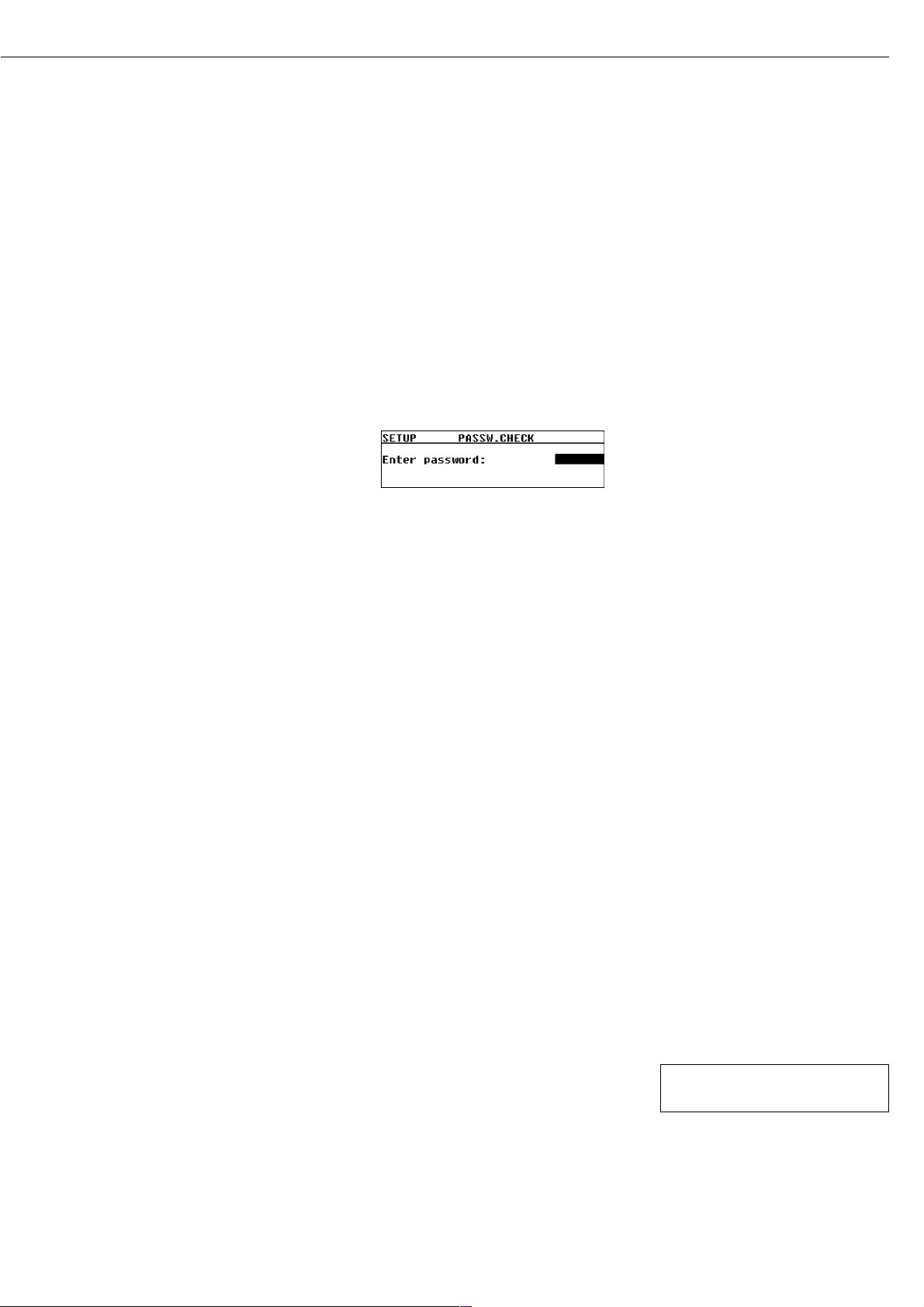
General Password
Enter/Change Password
§ Select the Setup menu:
Use the x or y key to select
SETUP in the Function line and press
u to confirm
§ Press the u key
> SETUP is displayed with submenus
§ Select a submenu (in this example,
“Device parameters”): Press the y
key and press u to confirm
> Password prompt is displayed.
$ Use the x and y keys to enter
the password (see page 9 for details on
alphanumeric input) and press u to
confirm each digit
§ Press u to confirm password
$ Display device parameters:
Press the y and u keys
> Device parameters are displayed
§ Select the password function:
Press the u key
> Password prompt is displayed, together
with current password
§ Enter a new password: Use the x
and y keys to enter the password
and press u to confirm
$ To delete the password, enter a “space”
and press the u key to confirm
§ Exit the Setup menu:
Press the c key twice
> Restart your application
General Password:
40414243
Page 53

Brief Instructions
Sartorius MA45
Overview of Key Functions
eOn/Off Key
Turn moisture analyzer on/off;
analyzer remains in standby mode when
switched off
c Clear Function
During analysis: Cancel function
(e.g., taring)
In menu: Delete input; exit current
menu level
u Enter
During analysis: Activate selected
function (e.g., taring, analysis, cancel)
In menu: Store selected setting/input
y Down/Back
In menu: Go to next menu item on
same level
In alphanumeric input: Show next lowest
number/letter
x Up/Forward
In menu: Go to previous menu item on
same level
In alphanumeric input: Show next
highest number/letter
r Print
Output readout or active data record via
the interface port to the external printer
WMA6026-e01111
Page 54

Moisture Analysis
Switch analyzer on: e key
Select drying program:
Select PROGRAM:
y and u keys
Use the y and u keys to select program
P1, P2 or P3
Add sample:
Close sample chamber:
Start analysis: START function and u key
or directly after closing sample chamber
Drying in progress: wait
Read off result:
Cancel password prompt, if necessary: c key
Exit program selection: c key twice
Open sample chamber:
Position sample pan:
Tare sample pan: TARE function and u key
P1 130oC Auto. 128oC 5.2min
S
1890
%L
PROGRAMM
NEXTSETUP
Page 55

Configuration (SETUP)
Activate menu: Use the y and u keys to
select the SETUP function; confirm
Select desired menu level: y and x keys
Exit menu level or exit SETUP: c key
Language
German
English
U.S. mode
Français
Italiano
Español
Select menu item and setting:
y, x and u keys
Device parameters
Password
Interface
Display contrast
Acoustic signal
Factory settings
isoTEST
Calibrate/adjust weighing system
Hardware tests
Info: Device data
Page 56

Drying Parameters (PROGRAM)
Activate menu: Use the y and u keys to
select the PROGRAM function; confirm
Heating program
Standard drying
MA30 mode
Select program P1, P2 or P3
Exit menu level or exit PROGRAM:
c key
Select menu item and setting:
y, x and u keys
Standby temperature
Initial weight
Start analysis
With stability when Enter is pressed
Without stability when cover is closed
End of analysis
Fully automatic
Semi-automatic
Time
Display mode
Moisture (%L)
Dry weight (%R)
Ratio (%LR)
Residual weight (g)
Residual weight (g/kg)
Print intermediate results
Factory settings
Page 57

Sartorius AG
Weender Landstrasse 94–108
37075 Goettingen, Germany
Phone +49.551.308.0
Fax +49.551.308.3289
www.sartorius.com
Copyright by Sartorius AG,
Goettingen, Germany.
All rights reserved. No part
of this publication may
be reprinted or translated in
any form or by any means
without the prior written
permission of Sartorius AG.
The status of the information,
specifications and illustrations
in this manual is indicated
by the date given below.
Sartorius AG reserves the
right to make changes to the
technology, features,
specifications and design of the
equipment without notice.
Status:
November 2001, Sartorius AG,
Goettingen, Germany
Printed in Germany on paper that has been bleached
without any use of chlorine
W3A000.MA45 · KT
Publication No.: WMA6025-e01111
 Loading...