

Sartorius MA100,MA50 Operating Instructions Manual
Operating Instructions
Sartorius Moisture Analyzer
Models MA100 | MA50
Electronic Moisture Analyzer
98648-008-50

The MA100 | MA50 Moisture Analyzer
can be used for quick and reliable
determination of the moisture content
of materials of liquid, pasty and solid
substances according to the method of
thermogravimetry.
The moisture analyzer saves work
and speeds up your routine procedures
through the following features:
– Fast analysis time, gentle and uniform
sample drying due to the round ceramic
IR heating element
– Quick determination of the drying
parameters and easy-to-set drying
programs due to automatic determination of the shutoff parameters for
semi-automatic analyses (asap mode)
– Setting the fully automatic end-point
recognition parameter for an analysis
only requires that you enter the drying
temperature
– Optimal adjustment of the moisture
analyzer to other methods of analysis
and adaptation to difficult samples
due to the semi-automatic end-point
recognition
– Quick drying without the risk of scorch-
ing the sample and preheating adapted
to the sample’s heat sensitivity by
selecting an adequate heating program
– High flexibility for analyzing the widest
variety of samples and storable programs to save time when changing to
different types of samples
– User-definable printouts that can
be customized before moisture analysis
runs
– Brief instructions on the moisture
analyzer provide quick answers
to frequently asked questions
The moisture analyzer is ideal as a
measuring and test instrument for in
incoming inspection, in-process
control and quality control due to the
following features:
– Convenient and reliable control of the
accuracy of the moisture analyzer
according to the DIN/ISO standards by
using the internal calibration weight
(MA100 only)
– reproTEST for quick determination of
the standard deviation (MA100 only)
– ISO/GLP-compliant recording capability;
printouts can also be generated with an
(optional) internal printer
– Optimal process control and quality
monitoring due to the statistical evaluation of up to 9,999 analyses/programs
– Password-protected drying parameters
The moisture analyzer meets the
highest requirements placed on the
accuracy and reliability of weighing
results through the following features:
– High repeatability by limiting the
exposure of the weighing system to
vibration during the start of an analysis
and better access to the sample chamber due to the motorized heating unit
– Excellent readability under any lighting
conditions and backlit display for
minimization of reading errors
– Removable sample chamber base plate
for easy cleaning of the sample chamber
and protection of the weighing system
from debris
Symbols
The following symbols are used in
these instructions:
● indicates steps you must perform
$ indicates steps you must perform only
under certain conditions
> describes what happens after you have
performed a certain step
– indicates that a list will follow
! indicates a hazard
For technical advice on applications:
Phone: +49.551.308.3160
Fax: +49.551.308.3495
2
Intended Use

2 Intended Use
3 Contents
4 Warning and Safety Information
Getting Started
5 Storage and Shipping Conditions
5 Unpacking
5 Instructions for Recycling
5 Equipment Supplied
6 General View of the Moisture Analyzer
7 Connecting the Moisture Analyzer
to AC Power
8 Leveling the Moisture Analyzer
8 Selecting the Brief Instructions
8 Turning On the Analyzer; Opening and
Closing the Sample Chamber
Operating Design
9 Keys
10 Operation: Analysis and Test Functions
11 Menu Operation and Drying Results
11 Data Output
12 Error Codes
12 Saving Data
Configuring the Moisture Analyzer
13 Setting the Language
14 Setting the Device Parameters
15 Entering or Changing the Password
17 Example: Setting the Time and Date
18 Device Parameters (Overview)
20 Configuring the Printout
24 Device Information
Operating the Moisture Analyzer
25 Weighing Function
25 Basics
27 Preparation
27 Adjustment to an Existing
Measuring System
28 Preparing a Sample
30 Setting the Drying Parameters
30 Drying Parameters (Overview)
35 Displaying Analysis Data
35 Identification Codes
36 Mode
36 Info
36 Statistics
37 Examples
3
Contents
51 “isoTEST” Calibration |
Adjustment Functions
51 Heater Adjustment
51 Weighing System Settings
56 Hardware Tests
58 Adjusting the Heater
58 Heating Unit Adjustment
59 Data Output
59 Output to the Moisture Analyzer
61 Interface Description
62 Data Output Format
63 Data Input Format
65 Digital Input/Output Ports
66 Pin Assignment Chart
67 Cabling Diagram
68 Error Codes
Care and Maintenance
70 Service
70 Repairs
70 Cleaning
70 Replacing the Fan Air Filter
71 Replacing the Fuses
71 Disassembling or Replacing
the Heating Unit
71 Safety Inspection
Overview
72 Specifications
74 Accessories (Options)
75 Declarations of Conformity
78 EC Type-Approval Certificate
79 Plates and Markings
80 Index
Appendix
Entering the General Password
This moisture analyzer complies with
the European Council Directives as
well as international regulations and
standards for electrical equipment,
electromagnetic compatibility, and the
stipulated safety requirements.
Improper use or handling, however,
can result in damage and/or injury.
Read these operating instructions
thoroughly before using your moisture
analyzer to prevent damage to the
equipment. Keep these instructions in
a safe place.
Follow the instructions below to ensure
safe and trouble-free operation of your
moisture analyzer:
! Use the moisture analyzer only for
performing moisture analysis of samples. Any improper use of the analyzer
can endanger persons and may result
in damage to the analyzer or other
material assets
! Do not use this moisture analyzer in a
hazardous area/location; operate it only
under the ambient conditions specified
in these instructions
– The moisture analyzer may be operated
only by qualified persons who are
familiar with the properties of the
sample to be analyzed
! Make sure before getting started that
the voltage rating printed on the
manufacturer‘s label is identical to your
local line voltage (see the section on
“Connecting the Moisture Analyzer to
AC Power” in the chapter entitled
“Getting Started”)
– The device comes with a power supply
that has a grounding conductor
– The only way to switch the power off
completely is to unplug the power cord
– Position the power cable so that it
cannot touch any hot areas of the
moisture analyzer
– Use only extension cords that meet
the applicable standards and have a
protective grounding conductor
– Disconnecting the ground conductor
is prohibited
– Connect only Sartorius accessories and
options, as these are optimally designed
for use with your moisture analyzer
– Protect the moisture analyzer from
contact with liquid
– If there is visible damage to the
moisture analyzer or power cord:
unplug the equipment and lock it in a
secure place to ensure that it cannot
be used for the time being
! Clean your moisture analyzer according
to the cleaning instructions only
(see “Care and Maintenance”)
Do not open the analyzer housing.
If the seal is broken, this will result in
forfeiture of all claims under the
manufacturer’s warranty.
In case you have any problems with
your moisture analyzer:
$ contact your local Sartorius office,
dealer or service center
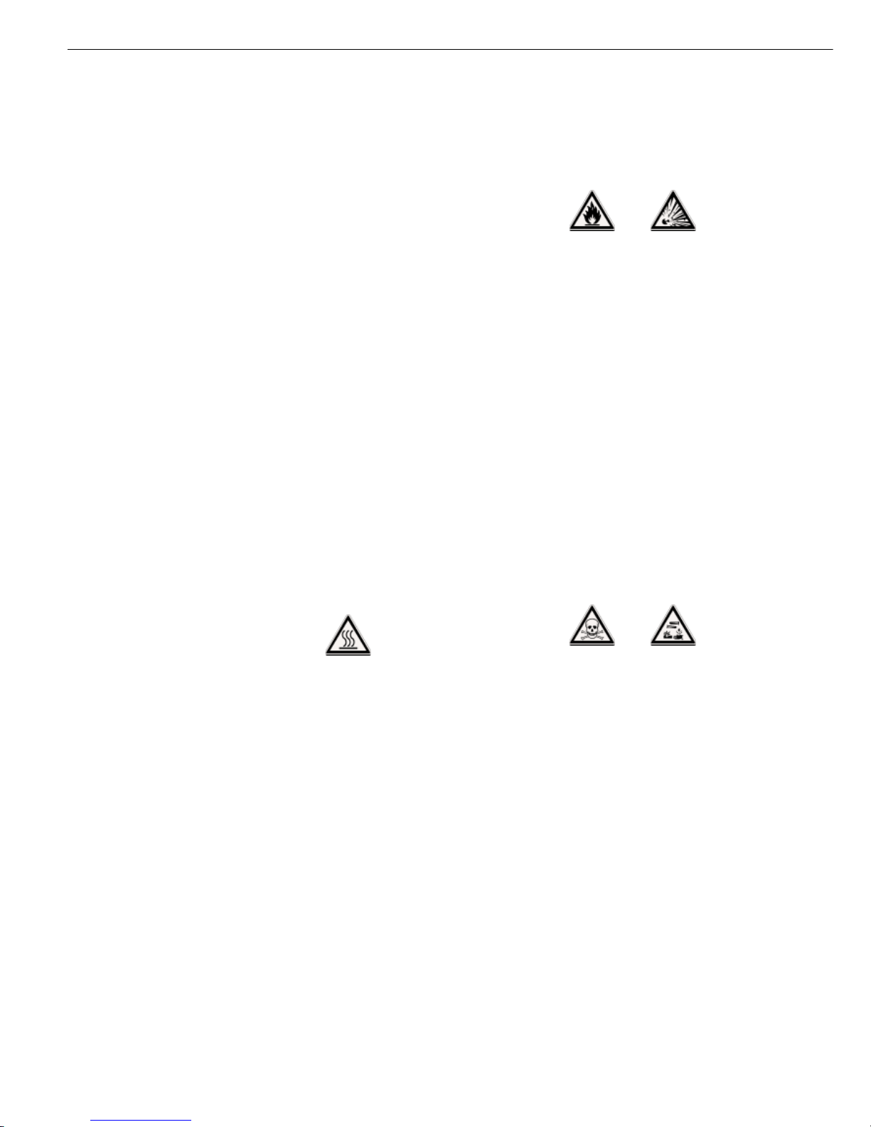
Warning: Severe Burns!
– When setting up the moisture analyzer,
leave enough space to prevent heat
from building up and to keep your
analyzer from overheating:
– leave 20 cm (about 8 inches) around
the moisture analyzer
– 1 m (3 ft.) above the device
– Do not put any flammable substances
on, under or near the moisture analyzer,
because the area around the heating
unit will heat up
– Be careful when removing the sample
from the chamber: the sample itself,
the heating unit and the sample pan
used can still be extremely hot
– Do not remove the heating unit during
operation: the heating element and
its protective glass panels can get
extremely hot!
– Prevent excess heat build-up around
the analyzer
Hazards for persons or equipment
posed by using specific samples:
Fire Explosion
– Flammable or explosive substances
– Substances that contain solvents
– Substances that release flammable
or explosive gases or vapors during the
drying process
In some cases, it is possible to operate
the moisture analyzer in an enclosed
nitrogen atmosphere to prevent the
vapor released during drying from
coming in contact with oxygen in the
surrounding atmosphere. Check on a
case-to-case basis whether this method
can be used, because installation of the
analyzer in too small an enclosed space
can affect its functions (for instance
through excessive heat build-up within
the analyzer). When in doubt, perform
a risk analysis.
The user shall be liable and responsible
for any damage that arises in connection with this moisture analyzer.
Poisoning Caustic burns
– Substances containing toxic or caustic
or corrosive substances: These may
be dried only under a fume hood. The
value for the “lower toxic limit“ in a
work area must not be exceeded.
Corrosion:
– Substances that release aggressive
vapors during the heating process
(such as acids): In this case we recommend that you work with small sample
quantities. Otherwise, vapors can
condense on cold housing parts and
cause corrosion.
The user shall be liable and responsible
for any damage that arises in connection with this moisture analyzer.
4
Warning and Safety Information

The moisture analyzer consists of a
heating unit, a weighing system, a
display and control unit and an optional
printer. In addition to the socket for
AC power (mains supply), it also has an
interface port for connecting peripheral
devices, such as a PC, an external
printer, etc.
Storage and Shipping Conditions
Allowable storage temperature:
0 ...+40°C
+32°F...+104°F
Do not expose the moisture analyzer
unnecessarily to extreme temperatures,
moisture, shocks, blows or vibration.
Unpacking the Moisture Analyzer
§ After unpacking the moisture analyzer,
check it immediately for any visible
damage as a result of rough handling
during shipment
$ If this is the case, proceed as directed
in the chapter entitled “Care and
Maintenance,” under the section on
“Safety Inspection”
It is a good idea to save the box and
all parts of the packaging until you have
successfully installed your moisture
analyzer. Only the original packaging
provides the best protection for shipment. Before packing your moisture
analyzer, unplug all connected cables
to prevent damage.
Instructions for Recycling
the Packaging
To ensure adequate protection for safe
shipment, your moisture analyzer has
been packaged to the extent necessary
using environmentally friendly materials. After successful installation of the
moisture analyzer, you should return
this packaging for recycling because it
is a valuable source of secondary raw
material. For information on recycling
options, including recycling of old
weighing equipment, contact your
municipal waste disposal center or local
recycling depot.
5
Getting Started
Warranty
Do not miss out on the benefits of our
full warranty. Please contact your local
Sartorius office or dealer for further
information. If available, complete the
warranty registration card, indicating
the date of installation, and return the
card to your Sartorius office or dealer.
Equipment Supplied
The equipment supplied includes the
components listed below:
– Moisture analyzer
– Power cord
– Pan support
– Shield disk
– Dust cover for keypad
– 80 disposable aluminum sample pans
– 1 pair of forceps
– 3 cards with brief instructions in
6 different languages
Installation Instructions
The moisture analyzer is designed to
provide reliable results under normal
ambient conditions in the laboratory
and in industry. When choosing a
location to set up your moisture
analyzer, observe the following so that
you will be able to work with added
speed and accuracy:
– Set up the moisture analyzer on a
stable, even surface that is not exposed
to vibrations
– Avoid placing the analyzer in close
proximity to a heater or otherwise
exposing it to heat or direct sunlight
– Avoid exposing the moisture analyzer to
extreme temperature fluctuations
– Protect the moisture analyzer from
drafts that come from open windows
or doors
– Keep the moisture analyzer protected
from dust, whenever possible
– Protect the moisture analyzerfrom
aggressive chemical vapors
– Do not expose the analyzer to
extreme moisture
– Make sure to choose a place where
excessive heat cannot build up. Leave
enough space between the moisture
analyzer and materials that are affected
by heat.
Conditioning the Moisture Analyzer
Moisture in the air can condense on the
surfaces of a cold moisture analyzer
whenever it is brought into a substantially warmer place. If you transfer the
moisture analyzer to a warmer area,
make sure to condition it for about
2 hours at room temperature, leaving it
unplugged from AC power. Afterwards,
if you keep the moisture analyzer connected to AC power, the continuous
positive difference in temperature
between the inside of the moisture
analyzer and the outside will practically
rule out the effects of moisture
condensation.
Setting up the Moisture Analyzer
§ Position the components listed below in
the order given:
– Dust cover over the keypad
– Shield disk
– Pan support; turn to the left or right,
press slightly until it stops and snaps
into place
– Disposable sample pan
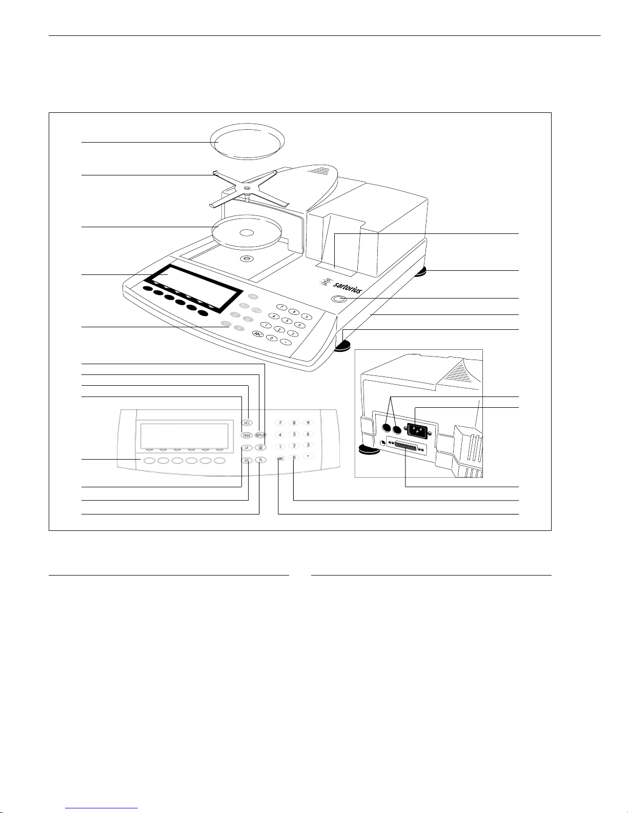
No. Designation Order no.
for replacement
1 Internal printer (option) YDS01MA
2 Leveling foot 69MA0091
3 Level indicator
4 Brief instructions
5 Fuse
6 Power socket
7 Interface port
8 Keys for numeric input
9 Toggle key for alphabetic input
10 Key for opening and closing the
sample chamber by the heating unit
11 CF key (clear function)
12 Line feed; press the key to advance
the paper by one blank line
13 6 function keys (soft keys)
No. Designation Order no.
for replacement
14 “isoTEST” key (calibration/
adjustment functions)
15 On/off key
16 “Setup” key
17 Print key
18 Keypad
19 Display
20 Metrological Data
(only for models MA100.-0CE)
21 Shield disk 69MA0093
22 Pan support 69MA0092
23 Disposable sample pan 6965542 (80 units)
Not shown:
Dust cover for keypad 6960MA01
Forceps 69MA0072
6
General View of the Moisture Analyzer
1
11
2
3
5
2
6
7
8
910
12
14
13
15
16
17
18
19
20
21
22
4
§ Check the voltage rating and the plug design
$ The heating unit of the moisture analyzer has been factory-set to 230 or 115 volts for
technical reasons. The voltage has been set as specified on your order. The voltage setting is
indicated on the manufacturer’s label (see the bottom of the analyzer), for example:
– 230 volts: MA50C-...230..
– 115 volts: MA50C-...115..
! If they do not match: To have the voltage setting changed, contact your local Sartorius
office or dealer, and do not operate your moisture analyzer in the meantime!
Use only
– Original power cords
– Power cords approved by a certified electrician/Sartorius service technician
– If you need to connect an extension cord:
Use only a cable with a protective grounding conductor
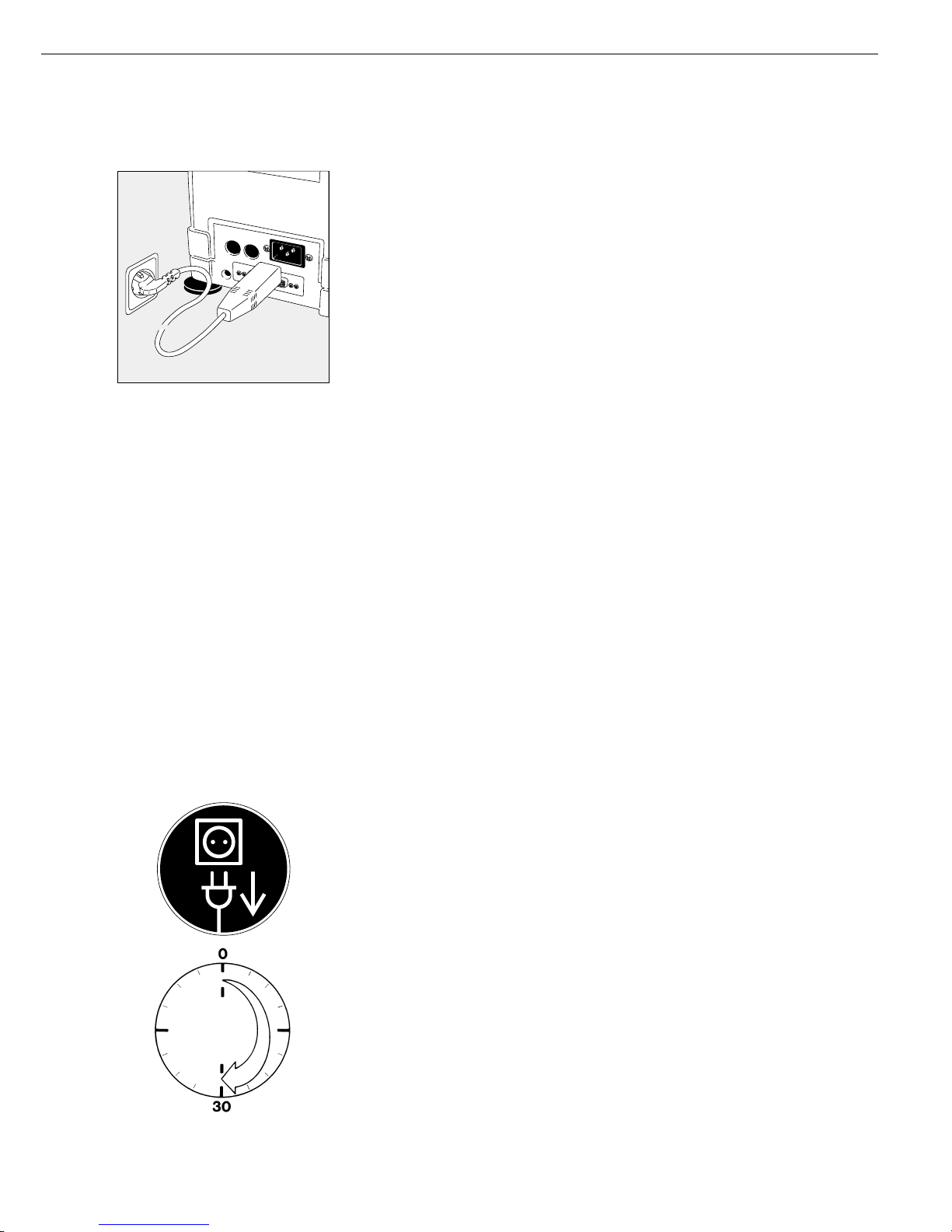
§ Connecting the moisture analyzer, rated to Class 1, to AC power (mains supply):
The moisture analyzer must be plugged into a properly installed wall outlet which has a
protective grounding conductor (PE)
Safety Precautions
If you use an electrical outlet that does not have a protective grounding conductor,
make sure to have an equivalent protective conductor installed by a certified electrician as
specified in the applicable regulations for installation in your country.
The protective effect must not be negated by using an extension cord without a protective
grounding conductor.
Information on Radio Frequency Interference
Note: This equipment has been tested and found to comply with the limits for a Class A
digital device, pursuant to Part 15 of the FCC Rules. These limits are designed to provide
reasonable protection against harmful interference when the equipment is operated in a
commercial environment. This equipment generates, uses, and can radiate radio frequency
energy and, if not installed and used in accordance with the instruction manual, may cause
harmful interference to radio communications. Operation of this equipment in a residential
area is likely to cause harmful interference in which case the user will be required to correct
the interference at his own expense. Changes or modifications not expressly approved
by Sartorius AG could void the user‘s authority to operate the equipment.
The AC adapter rated to Class 2 can be plugged into any wall outlet without requiring
any additional safety precautions. The ground or earth terminal is connected to the
housing, which can be additionally grounded, if required. The data interface is also
electrically connected to the scale housing (ground).
Connecting Electronic Devices (Peripherals)
§ Make absolutely sure to unplug the moisture analyzer from AC power before you connect
or disconnect a peripheral device (printer or PC) to or from the interface port.
Warmup Time
To deliver exact results, the moisture analyzer must warm up for at least 30 minutes after
initial connection to AC power or after a relatively long power outage. Only after this time
will the moisture analyzer have reached the required operating temperature.
Using Verified Moisture Analyzers as Legal Measuring Instruments in the EU*:
$ Make sure to allow the analyzer to warm up for at least 24 hours after initial connection to
AC power or after a relatively long power outage
* including the Signatories of the Agreement on the European Economic Area
Charging the Built-in Rechargeable Battery
Before initial operation, leave the moisture analyzer connected to the line current
(mains supply) for at least 10 hours to charge the built-in rechargeable battery. When the
analyzer is disconnected from line current, the analysis data is retained in memory for
approximately three months.
7
Connecting the Moisture Analyzer to AC Power
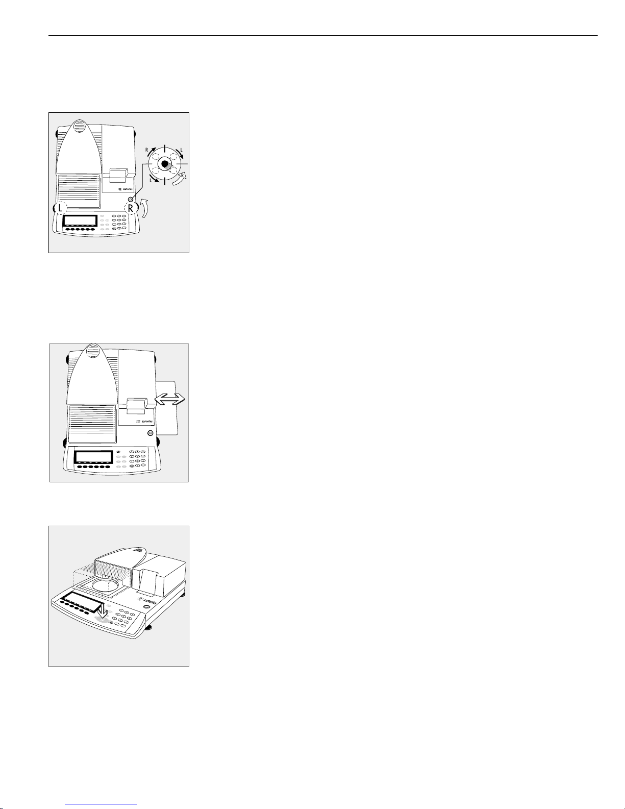
Leveling the Moisture Analyzer
Purpose:
– To compensate for unevenness at the place of installation
– To achieve perfectly horizontal positioning of the moisture analyzer
for consistent repeatability
– This is necessary especially for testing liquid samples that need to be at a uniform level
in the disposable sample pan
Always level the moisture analyzer again any time it is moved to a different location.
Only the 2 front feet are used for leveling.
§ Retract the both rear feet
§ Turn the 2 front feet as shown in the illustration until the air bubble is centered
within the circle of the level indicator
> Several leveling steps are usually required
§ Extend the 2 rear feet until they touch the surface on which the moisture analyzer rests
Selecting the Brief Instructions
The moisture analyzer has separate cards with brief instructions on its most important
functions. The following languages are included:
– English/Dutch
– German/Italian
– French/Spanish
To exchange the brief instruction card:
§ Pull out the brief instruction card on the right (you need to use a little force to overcome
the resistance which is used to keep the card in place)
To insert the card:
§ Slide the selected card into the slot
$ Pull out the card on the right to remove it, if necessary
Turning On the Analyzer; Opening and Closing the Sample Chamber
§ To turn on the analyzer: Press the e key
§ To open or close the sample chamber: Press the k key
> The motor opens or closes the sample chamber
Setting the Language
– See the section on “Setting the Language” in the chapter entitled
“Configuring the Moisture Analyzer”
Setting the Date and Time
– See the section on “Entering User Data” in the chapter entitled
“Configuring the Moisture Analyzer”
8

Operation of the moisture analyzer follows
a standardized “philosophy” which is
described below.
Keys
The moisture analyzer is operated either
using the keys on the display and
control unit or via a connected PC.
Operation using the keys is described
in the following.
Labeled Keys
These keys always have the function
indicated, but are not available at all times.
Availability of these functions depends
on the current operating status of the
moisture analyzer and its menu settings.
9
Operating Design
The keys have the following
functions:
e On/off key
Turns the moisture analyzer
on/off. The moisture analyzer
remains in standby mode
T isoTEST
Calibration/adjustment of the
weighing system and hardware
tests can be carried out
s Configuring the moisture
analyzer
Access to the Setup menu; exit
Setup
l Line Feed
(Optional) printer advances the
paper by one line
p Data Output
Press this key to output displayed
data via the interface port or to
generate printouts using the
(optional) printer
c Clear Function
Deletes keypad input
Interrupts calibration/adjustment
routines
k Arrow Key
Opens or closes the sample
chamber
0 ... 9. Numeric Keys
see the section entitled “Text
Input”
a Alphabetic Keys
see the section entitled “Text
Input”
Numeric Input
To enter numbers: Press the
0 1 … 9 . keys
To store numbers entered: Press the
corresponding soft key
To interrupt/cancel numeric input
digit by digit: Press the c key
Text Input
● To enter numbers: See the section
entitled “Numeric Input”
● To enter letters or characters:
Press the a key
> Letters are displayed in the bottom line
for selection
● To select a different letter: Press the
corresponding soft key to change the
letter shown
● To select the letter/character shown:
Press the corresponding soft key
> The selected letter is shown on
the display
$ Enter the next letter/character, if
desired, as above
$ To exit the letter input mode (i.e. if the
last character entered is a letter):
Press the a key
● To store a word: Press the corresponding
soft key (e.g.,
ID)
● To delete an input or character:
Press c key
● To delete user data: Enter .
“decimal point” or a space “ “ and
confirm by pressing Enter
F5F6 F4 F3 F2 F1
Prog. Info Stat. ID Mode Tara

Function Keys (Soft Keys)
The current function of a soft key is
indicated in the bottom line of the display
(footer).
Texts (as abbreviations) or symbols can be
displayed in the example shown below.
Texts (Examples)
Info:
Information about the “Phase Drying”
program
Prog.:
Select/configure the drying program
Stat.:
Statistics display/delete
ID:
Enter the ID number
Mode:
Change the parameters
Tare:
Tare the sample pan
The function keys are numbered (F1)
through (F6), from right to left.
Symbols
The bottom line shows the following
symbols:
ooReturn to Setup menu
(in the Setup menu:
exit the Setup program)
o Go back to the higher
selection level
O Show sub-items under the
active item
Q Move upward in the input/
output window
q Move downward in the input/
output window
l Set the selected menu parameter
There are two fundamentally different
types of display:
– display for analysis and test functions
– display for menu parameter settings
(e.g., SETUP, Mode, ID) and final results
(Info, Statistics)
Prog. Info Stat. ID Mode Tara
F5F6 F4 F3 F2 F1
Operation
Analysis and Test Functions
This display is divided into nine
sections.
Example: Moisture Analysis
Info Drying Program Line
The following information is displayed
here:
– Program name with 10 characters max.
(factory setting), e.g. BUTTER or
– Number of the selected drying program,
e.g. P1 (Configuration: Drying parameter: Mea. No. # with automatic
Counter: On)
– Temperature settings
– End of measurement criteria
Bar Graph:
The bar graph indicates the percentage
by which the weighing system’s capacity
is “used up” by the current sample on
the pan
The bar graph is shown if you have
selected
minimum and
maximum initial weight
or target value,
tolerance in %.
The following symbols may be
displayed here:
0% Lower load limit for initial
sample weight
100% Upper load limit for initial
sample weight
Bar graph showing 10% intervals
- Minimum tolerance
= Target value
+ Maximum tolerance
Info drying program/Test function
Bar graph
Measured value line
Text line
Soft key labels
Plus/minus sign
Stability
indicator
Unit
Symbol for drying
Symbol for printout
Plus/Minus Sign:
A plus or minus sign (F or H) is shown
here for a weight value (e.g., a calculated
value, when weighing in percent).
Measured Value Line:
This section shows the weighed or
calculated value or alphanumeric input.
Unit and Stability:
When the weighing system reaches
stability, the weight unit or calculation
unit is displayed here.
Symbol for Drying:
During the drying program, the following
symbol is displayed here:
Drying in progress
Symbol for Printout:
During the printout of the analysis results
and other data, the following symbols
appear in this column:
S
Print
Text Line:
Additional information is displayed here
(e.g.,operating state, operator guidance
prompts, analysis temperature and
measuring time, etc.)
Text line example for operator guidance
(e.g., “TARE: Tare sample pan”)
Soft Key Labels:
The current functions (abbreviations) of
the arrow keys (soft keys) are indicated
here. Please note that when we say “press
the X soft key,” we are referring to the
actual key indicated below the soft key
label displayed.
g
d= 0.01g
100%
000
F
S
Info Prog. Stat. ID Mode
A
H
L
S
T
P2 80/105/120 C Auto.
0%
TARE: Tare sample pan
a
d
0015
Tare
10

Menu Operation and Drying Results
This display is divided into three sections.
Line for Operating State:
The line for operating state indicates the
function of the current screen page.
In the Setup menu, the current menu path
is shown here.
Example for Setup, Language:
Input and Output Window:
This window contains either detailed information (e.g., on the active application) or
a pick list. A selected item is displayed
inversely (white letters on a black background). You can also enter information in
an active field in this window using the
alphanumeric keys.
Example for Setup, Parameter Settings:
The following symbol in the input or
output window indicates:
d this symbol marks the saved
menu setting
Soft Key Labels:
See the “Function Keys (Soft Keys)” on the
previous page
o Normal vibration
Strong vibration
SETUP LANGUAGE
Line for Operating State
Input and Output Window
Soft key labels
11
Parameter Settings
The parameters are configured in
menus. These menus have several
levels.
Example of the Setup Menu:
● To select a parameter:
Press the s key
● To move within a menu level:
Press the Q or q soft keys
● To select a menu item (submenu):
Press the O soft key
To set a parameter:
● Press the Q or q soft keys
repeatedly until the desired setting is
selected (displayed inversely)
● Confirm your selection by pressing the
l soft key
To change the numeric value of
a parameter:
● Press the Q or q soft keys
repeatedly until the desired setting is
selected (displayed inversely)
● Enter the desired number using the
0 1 ... 9 . keys
or the a soft key and enter the
desired letters
● Confirm your selection by pressing the
l soft key
To exit Setup: Press s or the
oo soft key
Data Output
You can choose between:
– internal printer (option)
– interface port for:
– Sartorius printer
(such as the YOP03-01)
– computer (PC)
– process logic controller (PLC)
– universal remote control switch
(Internal/External) Printer
You can configure the print functions to
meet your individual requirements by
selecting the corresponding menu code in
Setup. The printouts can be generated as
standard or ISO/GLP-compliant printouts.
ISO: International Organization
for Standardization
GLP: Good Laboratory Practice
You can have printouts generated automatically, or by pressing p; printout
generation can be dependent on or independent of the stability or time parameters
(for example, automatic when a drying
program starts, at specific time intervals,
at the end of a drying program).
See the section on “Data Output Functions” in the chapter entitled “Operating
the Moisture Analyzer” for a detailed
description of data output options.

Interface Port
You may choose to connect a different
peripheral device, such as one of the
following, to the interface port instead
of or in addition to the internal printer:
– external printer
– status indicators with digital input ports
– process logic controller with digital
input/output port
– a computer (PC) with a communications
port
The moisture analyzer can be monitored
and remote-controlled via the interface
port.
For a detailed description, see the
section on “Data Output Functions”
in the chapter entitled “Operating
the Moisture Analyzer.”
Error Codes
If you press a key that has no function,
or which is blocked at a certain point
in an application program, this error is
indicated as follows:
– a double-beep is sounded as
an acoustic signal if the key has
no function
– invalid input is indicated by an
error message
– incorrect operation is indicated by an
error code or error message
The response to an operator error is
identical for all operating modes.
See the chapter entitled “Error Codes”
for a detailed description.
Saving Data
Storing Parameter Settings
The parameter settings in the Setup
menu and for drying programs are
active when you switch on the moisture
analyzer. The parameter settings,
selected with the
Mode soft key dur-
ing an analysis, are not saved (exception: limits for the control function).
In addition, the factory settings can be
restored.
Saving Parameter Settings
You can assign passwords in order to
block access to:
– user-configured drying programs
– setting mode for device parameters
– printout configuration
If no password has been assigned,
anyone can access drying programs,
“SETUP: Device parameters” and
“Printout configuration” without
entering a password.
If you assign a password and then
forget what the word is, you can use
the General Password (see Appendix)
to access these menus.
12
Purpose
You can configure your moisture
analyzer to meet individual requirements by entering user data and
setting selected menu parameters in the
Setup menu.
The Setup menu is divided into
the sections:
– Language
– Device parameters
– Printout configuration
– Device information
13
Configuring the Moisture Analyzer
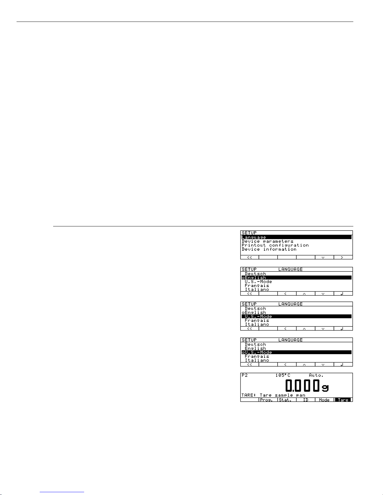
Setting the Language
You can choose from 5 languages for
the information display:
– German
– English (factory setting)
– English with U.S. date/time format
– French
– Italian
– Spanish
Example: Selecting the language: “U.S. Mode”
Step Key (or Instruction) Display/Printout
1. Select Setup menu s
2. Confirm the language O soft key
3. Set the language “U.S. Mode” Q soft key
4. Store the language l soft key
5. Exit Setup oo soft key
Setting the Device Parameters
(DEVICE)
Purpose
Device configuration, i.e., to meet
individual requirements by selecting
predefined menu parameters in the
Setup menu. You can block access to
the menu by assigning a password.
Features
The device parameters are combined
in the following groups:
– Password to the Setup menu
– User ID
– Weighing parameters
– Interface
– Internal printer (option)
– Keypad
– Display
– Clock
– Extra functions
– Factory settings
You can view, enter or change the
following parameters:
Password
– Password for access to the SETUP
menu: “Device parameters,” “Printout
configuration” and “Drying programs”
(8 characters max.)
User ID
– ID codes:
User ID (20 characters max.)
Weighing parameters
– Adjustment to the ambient conditions
– Weight set number for
calibration/adjustment:
W ID (weight ID; 14 characters max.)
– Exact calibration weight value for
calibration/adjustment of the analyzer,
such as for adjustment according to
a DKD certificate (see the section on
“Calibration/Adjustment” in the chapter
entitled “Operating the Moisture
Analyzer”)
Interface
– SBI operating mode
Simple record of analysis results for PC
or external printer, factory setting for
YDP03-OCE printers
Format: baud rate, number of data bits,
parity, stop bits, handshake
– xBPI operating mode
Function-oriented interface with clear
data transmission
Network address: enter a number from
0 to 31; factory setting: 0
– Sartonet via RS-485 interface
Network address: enter a number from
0 to 31; factory setting: 1
Keys
– CF function: delete entire input
or last character
– Block key functions
Display
– Background
– Contrast/angle of the display (enter a
number from 0 to 4; factory setting: 2)
Clock
– Time (hh.mm.ss; hh can be entered
without a preceding zero)
– Date (dd.mm.yy or mm.dd.yy when
you select “English with U.S. date/time”
as the language”)
Extra Functions
– Acoustic signal on or off
– Functions for external universal remote
control switch, extra keyboard or bar
code scanner
Factory Settings
Parameters: The factory-set configurations are identified by an “o” in the
list starting on page 18.
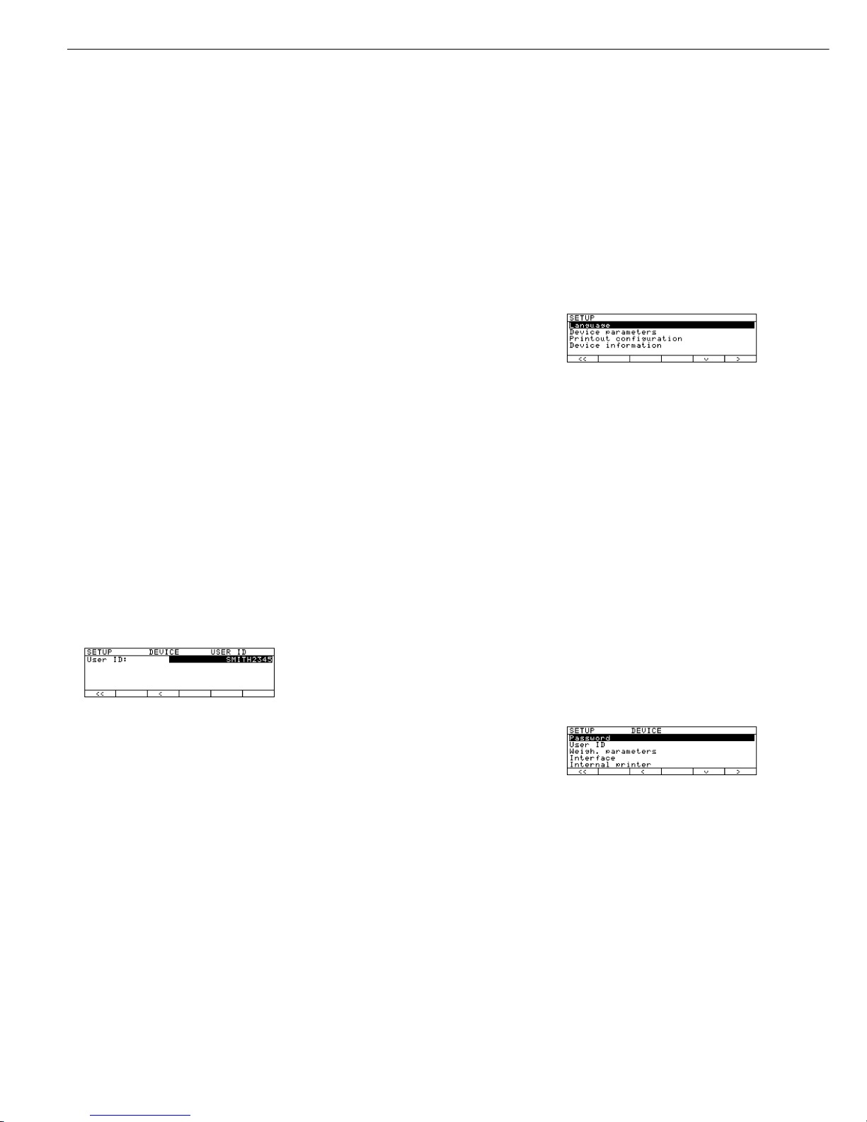
Preparation
Display existing “Device parameters”
§ Select the Setup menu:
Press the s key
> SETUP is displayed:
§ Select “Device parameters”:
Press the q and O soft keys
If no password has been assigned,
anyone can access “SETUP: Device
parameters” and “Printout configuration” without entering a password
If you have already assigned
a password:
> The password prompt is displayed
$ If access is blocked by a password:
enter the password using the alphanumeric keys
$ If the last character of the password is a
letter: conclude input by pressing a
§ Confirm the password and display
“Device parameter”:
Press the l soft key
> Device parameters are displayed:
14

Entering or Changing the Password
– Password for access to the following
functions, entered with 8 characters
max.:
– SETUP parameters
– Data record configuration
– Edit or copy drying program
§ Select the Setup menu:
Press the s
> SETUP is displayed
§ Select parameters:
Press the q und O soft keys
If you have already assigned
a password:
> The password prompt is displayed:
$ Enter the password
$ Confirm the password and
display the parameters:
Press the l soft key
§ Write down the password here
for easy reference:
Password = .............................
If you assign a password and then
forget what the word is:
$ Enter the General Password
(see Appendix)
$ Confirm the password and display
the parameters:
Press the l soft key
> Parameters are displayed
§ Select the password-setting function:
Press the q or Q soft key repeatedly
and O soft key until
> Password: and any existing
password are displayed:
15
§ New password: Enter the numbers
and/or letter of the new password
(8 characters max.)
If “none” is displayed as a password:
this means no password has been
assigned
To delete the user password:
Enter . and confirm
§ To confirm your entry:
Press the l soft key
§ Exit the Setup menu:
Press the oo soft key
> Restart the application
Extra Functions
§ Exit the Setup menu:
Press the oo soft key
> Restart the application
§ Printout the parameter setting:
– If “Device parameters” are displayed:
Press the p soft key
> Printout (example)
Printouts with more than 20 characters
are cut off
-------------------SETUP
DEVICE
--------------------
User ID
User ID:
ABC123456
Weighing parameters
Adapt filter
Normal vibration
Calibration/Adjust
Wt.ID (W ID):
123
Cal./Adj. wt.:
50.000 g
Interface
SBI
Baudrate
1200 baud
Number of data bit
7 bit
Parity
Odd
Number of stop bit
1 stop bit
Handshake mode
Hardware 1 char
etc.
● Reset the device parameters to
the factory settings:
See the section on selecting the factory
settings in the chapter entitled “Device
Parameters (Overview)”
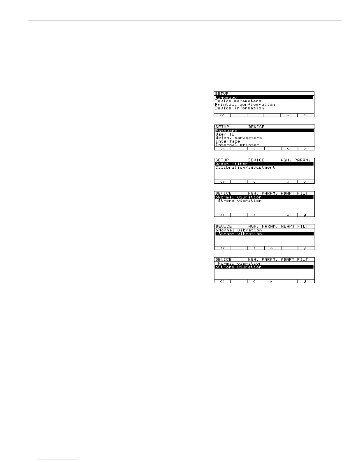
Example 1:
Adapt filter to the ambient condition: “Strong vibration”
Step Key (or Instruction) Display/Printout
1. Select Setup menu s
2. Select and confirm q soft key, then the
“Device parameters” O soft key
3. Select and confirm q soft key twice,
“Weigh. parameters” then the O soft key
4. Confirm menu item O soft key
“Adapt filter”
and select next menu level
5. Select menu item q soft key
“Strong vibration”
6. Confirm menu item l soft key
“Strong vibration”
7. Select other menu items, if desired q Q soft key(s)
8. Store the setting and oo soft key
exit Setup menu
16
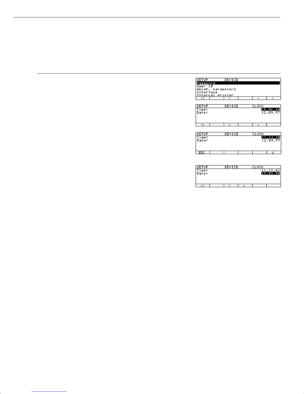
Example 2:
Set time and date
Step Key (or Instruction) Display/Printout
1. Select Setup menu; s, then
select “Device parameters” q and O soft keys
2. Set clock q and
O soft keys repeatedly
3. Enter the time 1 1 . 1 2
. 3 0
4. Set the time according to
your local clock l soft key
5. Enter the date 1 3 . 0 3
. 9 9
6. Store the date l soft key
7. Enter other date, if desired q Q soft key(s)
8. Exit Setup menu oo soft key
17

Device Parameters (Overview)
ο factory setting
√ user-defined setting
Setup – Password empty Enter 8
Device characters max.
parameters User ID empty Enter 20
characters max.
Weighing Adapt filter ο Normal vibration
parameters Strong vibration
Calibration/ Weight set number None Enter 14
adjustment (weight ID) characters max.
Calibration/adjustment 50.000g Enter exact
weight value weight value
Interface SBI Baud rate 150 baud
300 baud
ο 1200 baud
2400 baud
4800 baud
9600 baud
19200 baud
Number of data bits ο 7 bit
1
)
8 bit
Parity None
2
)
ο Odd
Even
Number of stop bits ο 1 stop bit
2 stop bits
Handshake Software handshake
mode ο Hardware handshake
1 character after CTS
xBPI Network address 0 Enter any number
from 0 through 31
YDP01IS
YDP01IS label
(Label printout)
Sartonet Network address 1 Enter any number
from 1 through 31
YDP02IS
For keys, display and clock see next page
1
) not if “None” parity is selected
2
) only if 8 data bits selected
18
Factory setting
Factory setting
Factory setting

Setup – Internal printer ο Off
Device (option) On
parameters
Keys CF function Delete entire
for input input
ο Delete last
character
Block ο All keys unblocked
key functions All keys blocked except
for s, e
Alphanumeric
keys blocked
Display Background ο White
Black
Contrast Contrast (0 to 4) Selection: 0
1
ο 2
3
4
Clock Time: Enter
hh.mm.ss
Date: Enter dd.mm.yy or
mm.dd.yy
(01.01.97)
Extra Acoustic signal ο On
functions Off
Function: ο p key
external switch F1 function key
(right-hand soft key)
c key
Open or close
sample chamber
Bar code scanner /
Extra keyboard
Factory No
settings Yes
19
Werkseinstellung
Factory setting
Factory setting

Configuring the Printout
(CONFIG)
Purpose
You can configure individual printout
formats for each application.
All analysis printouts have basic factory
settings.
You can block access to the “Printout
configuration” data by assigning
a password.
Features
– Maximum items in a data record: 30
– Header, footer,
intermediate results, statistics and
information records can be configured
separately
– Printout header is output when starting
moisture analysis
– Intermediate records are output
during the moisture analysis runs by
pressing p or
at each printout interval
– Footer printed out at the end of
a moisture analysis
– Statistics are printed out while the
statistics are displayed by pressing p
(MA100 only):
– Information on phase drying is printed
by pressing p while the information
is displayed
– Printout items can be deleted
individually
– “Form feed” in a printout footer:
Select the “YDP01IS label” print mode
to configure automatic form feed up
to the beginning of the next label
Extra Functions
§ Exit “Printout configuration”:
Press the oo soft key
> Restart the application
Printout LIST or SELECT
– LIST: Output of the current printout
list
SELECT: Print currently
selectable items
§ When the select bar is on LIST or
SELECT: Press p
> Printout (example)
PRINT HEADER
LIST
====================
Blank line
GLP header
Program name
Heating param.
Standby temp.
Start parameter
End parameter
Initial weight
-------====================
etc.
Output of All Printout Settings:
– When the select bar is on printout
overview (SETUP CONFIG.):
Press p
> Printout (example)
--------------------
13.07.1999 13:08
Mod. MA100C
Ser. no. 90706913
Ver. no. 01-38-07
ID
-------------------SETUP
CONFIG.
-------------------Printout header
Blank line
GLP header
Program name
Heating param.
Standby temp.
Start parameter
End parameter
Initial weight
--------
Intermediate result
Analysis time
Analysis result
Printout footer
-------Ending time
Final weight
Final result
--------
etc.
§ Reset “Printout Configuration” to the
factory settings:
See “Printout configuration”
Set Printouts to
Factory Settings and confirm
with YES.
20

Data Items for the Printout:
Parameter Display text Print- Inter- Print- Statistics Info Printout (Example)
out mediate out
header result footer
Blank line 1) Blank line +* ++* +* +*
Dotted line 1) -------- +* ++* +* +* --------------------
GLP header
GLP header +* +* +* --------------------
13.07.1999 13:06
Mod. MA100C
Ser. no. 90706913
Ver. no. 01-38-07
ID WORKSTAT 234
--------------------
GLP footer
GLP footer +* +* 13.07.1999 14:06
Name:
--------------------
Date/time Date/time +++++13.07.1999 13:06
Time with seconds Time +++++ 13:06:45
User ID
(from Setup: Device) User ID +++ID WORKSTAT 234
Identification code 1 ID1 +++++ID1 SARTORIUS
Identification code 2 ID2 +++++ID2 GOETTINGEN
Identification code 3
ID3 +++++ID3
WEENDER LANDSTRASSE
Identification code 4 ID4 +++++ID4 LOT 15
Name in program memory Program name +* +* +* Prg 1 BUTTER
Heating program with parameters
Heating param. +* Heating STANDARD
Fin.temp 105 'C
Standby temperature Standby temp. +* Stdby temp. OFF
Start parameter Start parameter +* Start W/STABIL.
End parameter End parameter +* End AUTOMATIC
Preset tare weight Preset tare + PTare 0.000 g
Initial weight Initial weight +* IniWt + 5.712 g
Number of current analysis Analys no. + #1
Current weight CurrWt + CurrWt+ 5.1357 g
Analysis time according
to current display Analysis time ++* Time 1.0 min
Analysis result according
to current display Analys. res. ++* Res + 0.91 %L
Analysis time and result
according to current display Analys time/res. +* 1.0 + 0.91 %L
Form feed Form feed +
Space for signature, ID
Name +++Name:
Final weight Final weight +* FinWt + 5.1357 g
Time at end of analysis Ending time + Time 15.0 min
Final result according
to current display2) Final result + Res + 9.85 %L
Analysis time and result
according to current display2) Final time/res. +* 15.0 + 9.85 %L
Phase drying Res1 + 4.45 %L
intermediate results
Phase results ++* Res2 + 3.15 %L
Res3 + 2.25 %L
* Factory setting
1
) Print items can be selected more than once
2
) “asap” result additionally printed at the end
of analysis in the “asap” mode
21
asap
Difference 1.2 %
Interval 24 s ec
or
asap
Canceled

Parameter Display text Print- Inter- Print- Statistics Info Printout (Example)
out mediate out
header result footer
Text line “Statistics” Statistics ID + STATISTICS
Number of analyses Number of analys. +* n5
Mean value Mean value +* Avg. + 4.84 %L
Standard deviation Std. deviation +* s 0.05 %L
Minimum Minimum +* Min + 4.80 %L
Maximum Maximum +* Max + 4.90 %L
Text line “ANALYSIS INFO” Info ID +* ANALYS.INFO
* Factory setting
22
23
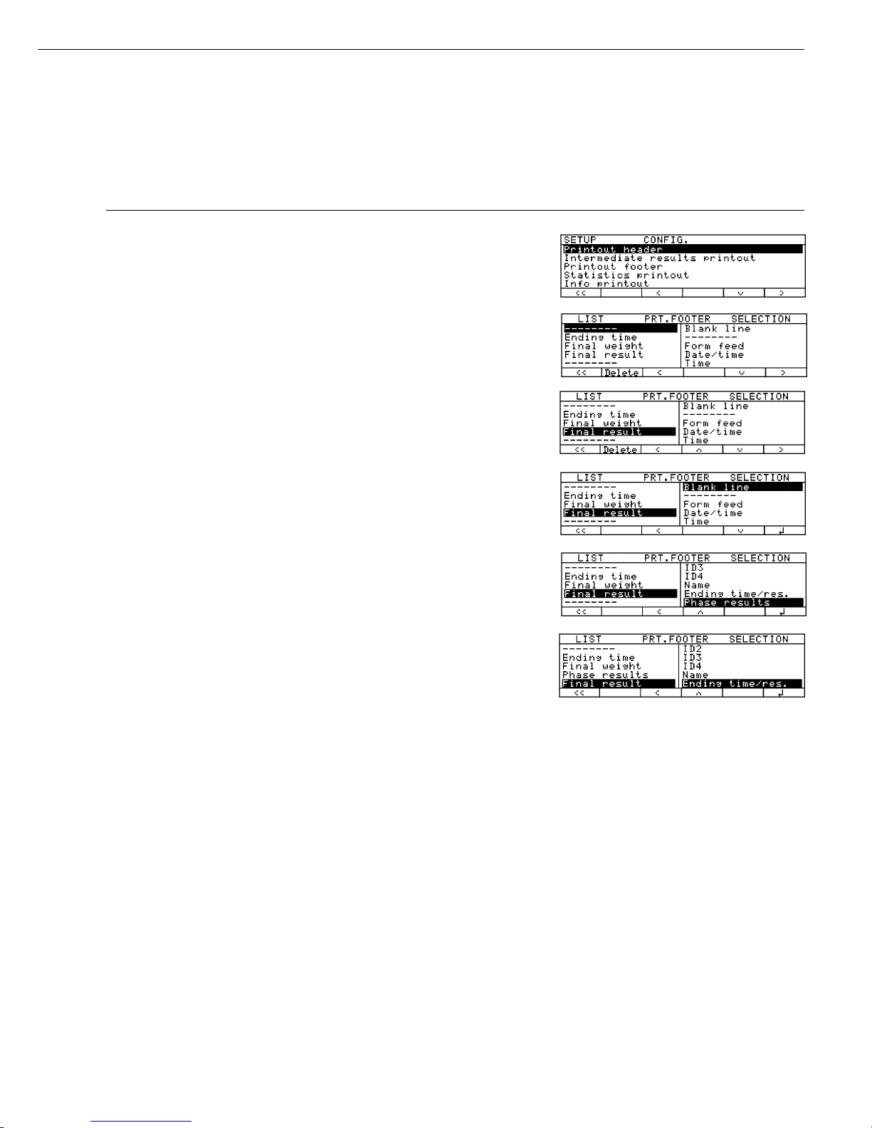
Example:
Adding the Item “Phase Results” to Configure the Printout Footer
Step Key (or Instruction) Display/Printout
1. Select Setup menu; s, then
Select “Printout q soft key twice,
configuration” then O soft key
2. Select printout footer q soft key twice,
then O soft key
3. Use the select bar to define q soft key repeatedly
the position for printout items
“Phase results” on the LIST
4. Change to Select O soft key
5. Select “Phase results” q soft key repeatedly
6. Include phase results l soft key
in the list
7. Select or delete other q Q l soft key
printout items, if desired or
oq Q Delete soft key(s)
8. Configure other analysis o q Q O soft key(s)
printouts, if desired
9. Exit Setup menu oo soft key
10. Perform moisture analysis p
and press --------------------
Time 15.0 min
FinWt + 9.5819 g
Res1 + 12.05 %L
Res2 + 7.12 %L
Res3 + 4.96 %L
C-Res + 24.13 %L
--------------------
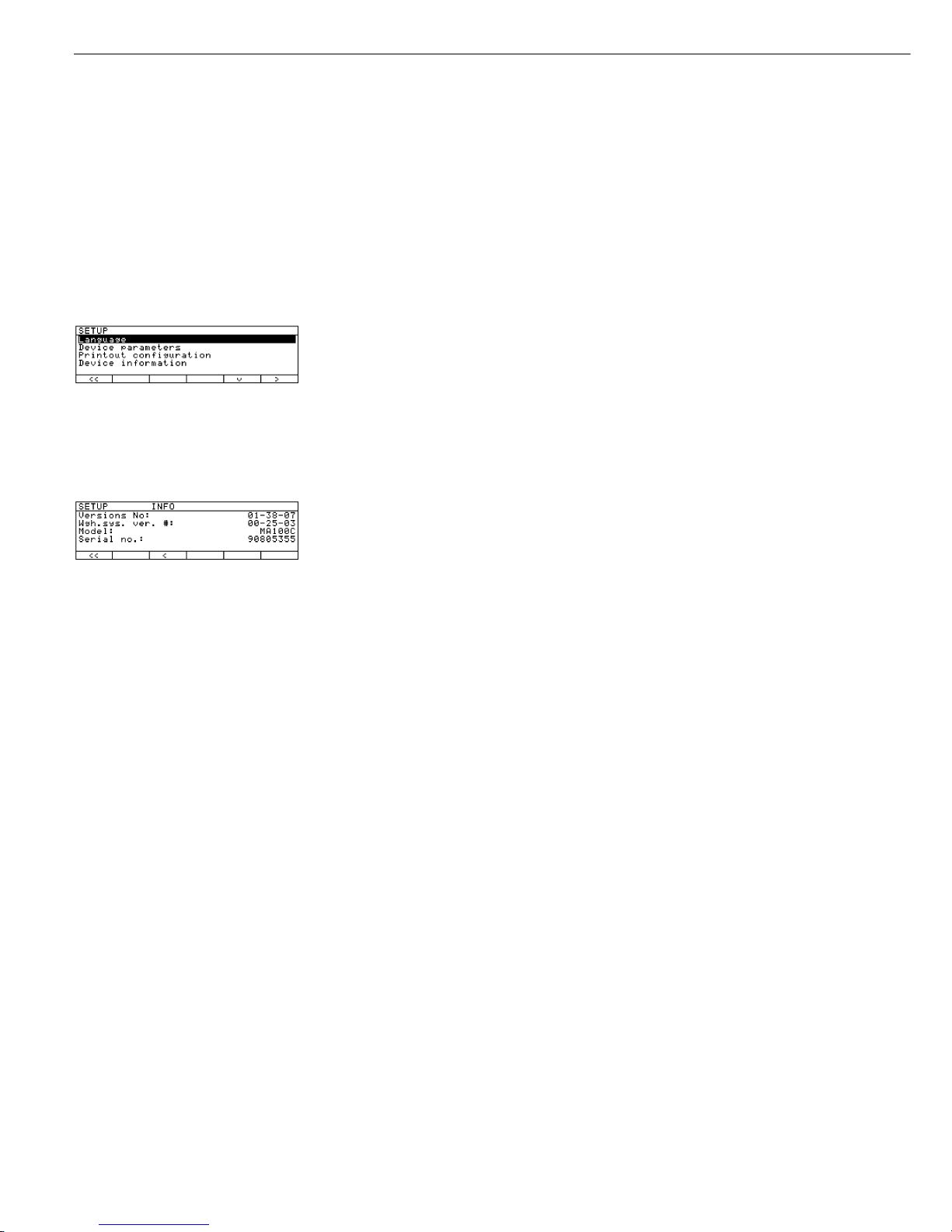
Device Information
Purpose
Display of device information
Display Device Information
§ Select Setup menu:
Press the s soft key
> “SETUP” is displayed:
§ Select “INFO:
Device information”:
Press q soft key three times,
then O soft key
> Device information is displayed:
§ Printout information:
Press p
> Printout (example)
--------------------
13.07.1999 13:02
Mod. MA100C
Ser. no. 90805355
Ver. no. 01-38-07
(Operating program version)
ID BECKER123
(User ID)
-------------------SETUP
INFO
-------------------Versions No:
01-38-07
(Operating program version)
Wgh.sys ver.
00-25-03
(Wgh.sys.program version)
Model:
MA100C
Serial no.:
90805355
--------------------
§ Reset to SETUP Overview:
Press the o soft key
§ Exit SETUP:
Press the oo soft key
> Original settings are restored
24
Weighing Function
Purpose
The MA100/MA50 moisture analyzer
can be used for quick and reliable
determination of the moisture content
of materials of liquid, pasty and solid
substances according to the method of
thermogravimetry.
Notes on Models MA100C-0CE230V1,
MA100H-0CE230V1:
The models MA100C-0CE230V1,
MA100H-0CE230V1 are delivered with
initial calibration ex factory.
Do not exceed the given ambient
temperature range (+15° to +25°C) stated
on the manufacturer’s ID label. The
verifiable weighing program is designated
by the Q symbol in the display.
To ensure reliable measurements, allow
the analyzer to warm up before switching
to the verifiable weighing program.
An internal calibration/adjustment must
be conducted before each measurement
series (see page 54). This applies until
the analyzer has cooled down to ambient
temperature.
25
Operating the Moisture Analyzer
Basics
The moisture of a material is often
mistakenly equated with its water
content. In fact, the moisture of a
material includes of all the volatile
components which are given off when
the sample is heated, resulting in a
decrease in sample weight. Among
such volatile substances are:
– water
– fats
– oils
– alcohols
– organic solvents
– flavorings
– products of decomposition (when a
sample is overheated)
There are many methods to determine
the moisture content of a substance.
Basically, these methods can be divided
into two categories:
When absolute methods are used, the
moisture content is directly determined
(for example, as a weight loss registered
during the drying routine). These
methods include oven drying, infrared
drying, and microwave drying. All
three of these methods are thermogravi-
metric.
When deductive methods are used, the
moisture content is indirectly determined.
A physical property, which is related to
the moisture in the substance, is measured
(e.g., absorption of electromagnetic rays).
These methods include Karl-Fischer
titration, infrared spectroscopy, microwave
spectroscopy, etc.
Thermogravimetry is the process of determining the loss of mass that occurs when a
substance is heated. In this process, the
sample is weighed before and after being
heated, and the difference between the
two weights is calculated.
In a conventional drying oven, circulating
hot air warms the sample from the outside
to the inside. Efficiency is lost during
drying because as the moisture evaporates,
it cools the sample surface.
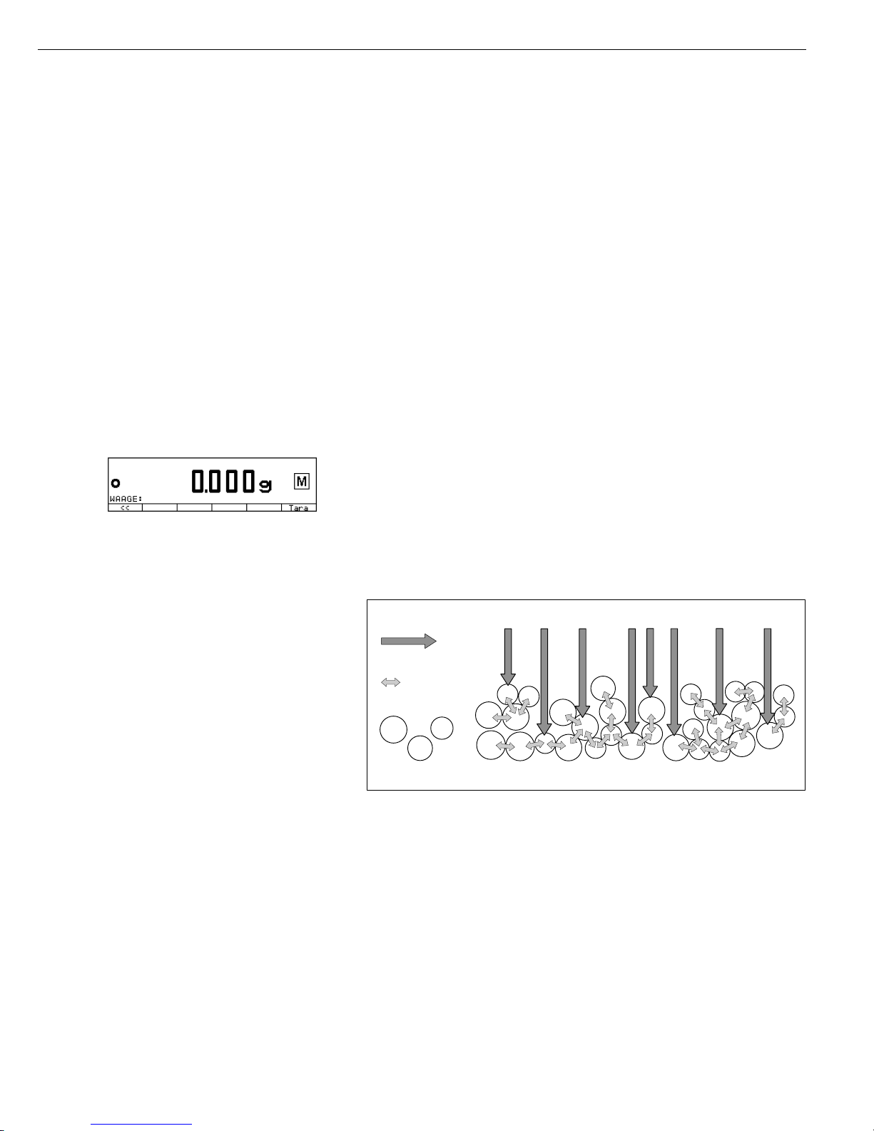
By contrast, infrared rays (IR rays) penetrate a sample without being impeded.
Having reached the interior of a sample,
they are converted into heat energy, which
stimulates evaporation, thus drying the
sample. A small part of the IR rays is
reflected from the surface of the substance.
IR-Strahlung
Substanz
Wärmeenergie
IR rays
thermal energy
substance

The quantity of reflected IR rays depends
to a great extent on whether the substance
is light or dark-colored.
Dark Substance Light Substance
Low Reflection High Reflection
How the rays penetrate the sample
depends on the sample’s degree of lighttransmitting capacity. If the degree of
light-transmitting capacity is low, the rays
can penetrate only the uppermost layers
of the sample. The heat conductivity of
the sample dictates the degree to which the
heat can be transmitted to the underlying
layers. The higher the conductivity, the
faster and more uniformly the substance
is heated.
The substance should be applied to the
sample pan in a thin, even layer. A height
of approximately 2–5 mm for 5–15 g
substance weight has proved to be ideal.
Otherwise, the sample will not be dried
completely or the analysis time will be
unnecessarily extended, a crust/skin will
form on the surface of the sample or the
sample will scorch, and the analysis results
obtained will not be reproducable, and
therefore, cannot be used.
Incorrect Application of a Sample
When preparing a substance for analysis,
you should use methods that do not
generate heat so that the sample does not
lose moisture before it is analyzed.
Perform initial analysis of a new substance
to test how the IR rays are absorbed by the
sample and converted into heat. The
printout of the intermediate values of the
drying process provides you with this
information at an early stage.
Experience has shown that the temperature
setting selected during the infrared
drying is usually lower than the temperature setting used when working with
a drying oven.
In many cases, the fully automatic shutoff
mode will meet your requirements.
If the final result is higher or lower than
expected, try varying the temperature
setting before resorting to a different
shutoff parameter.
When analyzing samples that lose their
moisture only very slowly or when operating a cold moisture analyzer, the fully
automatic mode may end the drying routine too early, if it does not detect any
analyzable progress in the drying routine
under these conditions. In this case, preheat the moisture analyzer for 2–3 minutes
before starting the drying routine or select
a different shutoff parameter.
The Sartorius Moisture Analyzer
Applications Guide will provide you with
important information on the use of
your moisture analyzer.
26

Preparation
Before drying a sample, you must carry
out the following preparations:
– Adjustment to the available measuring
system (if required)
– Sample preparation
– Setting the parameters for drying
program
27
Adjustment to an Existing Measuring System
A moisture analysis method often replaces another drying method (e.g., the oven drying
method), because it is simple to use and requires shorter analysis time. In this case,
you should adapt this method to that of the moisture analyzer in order to obtain values
comparable to those yielded by your standard reference method.
● Perform parallel measurements: take a fresh sample and divide it in half
● Determine the moisture content of the first half using your standard method of analysis
● Analyze the second half of the sample in the moisture analyzer.
Use the following settings:
– fully automatic mode for the shutoff parameter
– lower temperature settings than for the oven drying method
– temperature setting for organic substances: 80 – 100°C
– temperature setting for inorganic substances: 140 – 160°C
$ If the result for the second part does not correspond to that of the first:
– first, repeat the analysis using a different temperature setting
– then use the semi-automatic mode for the shutoff parameter (such as 5 mg/30 s
or the asap mode)
asap stands for “automatic searching/automatic programming”. The asap mode monitors
the drying process and, at the press of a key, calculates a semi-automatic shutoff
parameter for the expected results of the analysis. It then saves the parameter in a
program routine.
$ Vary the shutoff parameter, if required:
– Increase end-point recognition: set the parameter to 2 mg/30 s or 5 mg/60 s
– Decrease end-point recognition: set the parameter to 10 mg/30 s or 5 mg/10 s
 Loading...