

Sartorius
M3P, M3P-000V001
Electronic Microbalances
Installation and Operating Instructions
2
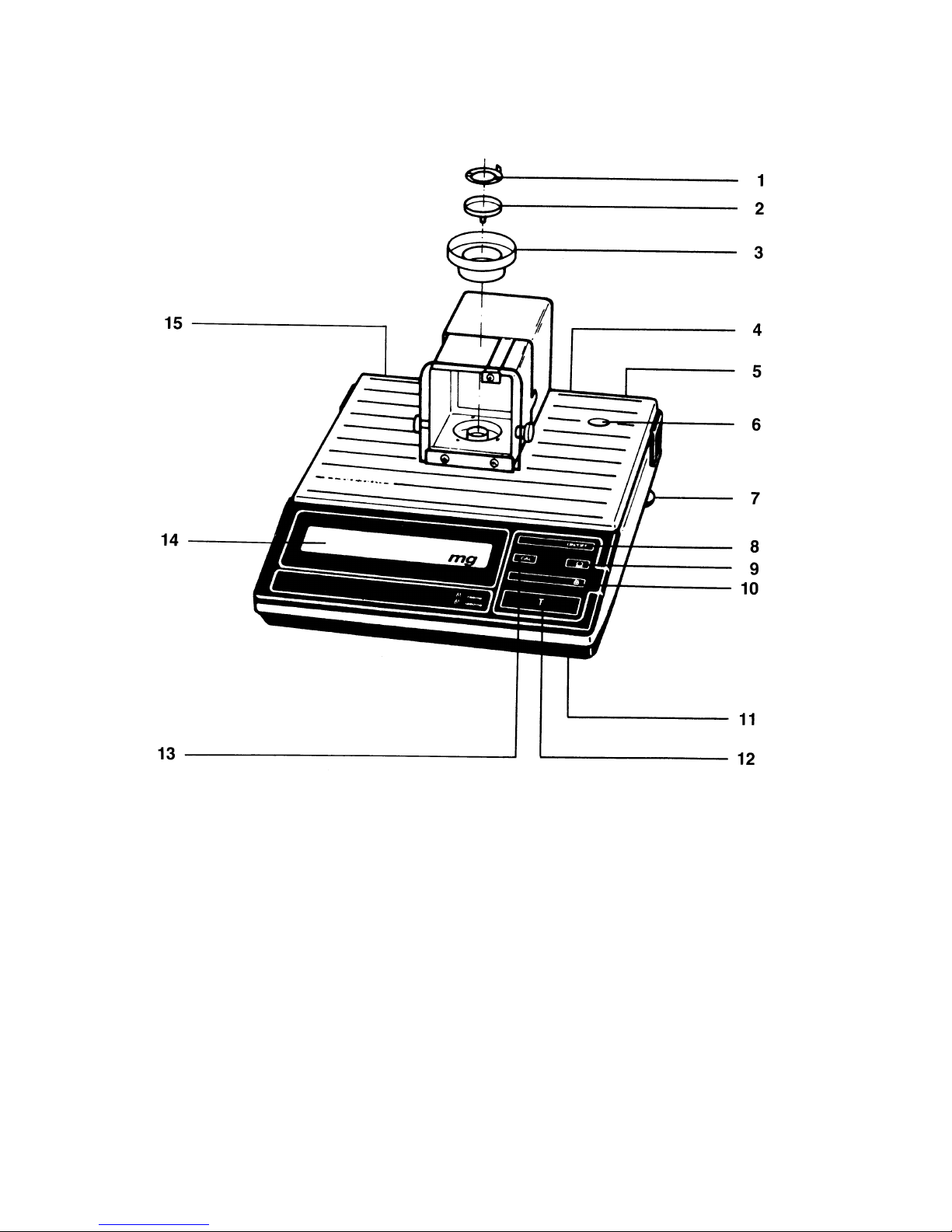
M3P
1
Weighing pan
11
Menu access switch
(for the balance operating program)
2
Pan support
12
Tare control
3
Interior draft shield
13
CAL key
4
Interface
14
Weight display
5
Power receptacle
15
Manufacturer’s label
6
Level indicator
16
Spacer
7
Leveling foot
17
Perforated filter pan holder
(for large filter weighing pan)
8
ON/OFF key
18
Filter pan holder (for small filter weighing pan)
9
Print key
19
Small filter weighing pan
10
Range expansion key
20
Large filter weighing pan
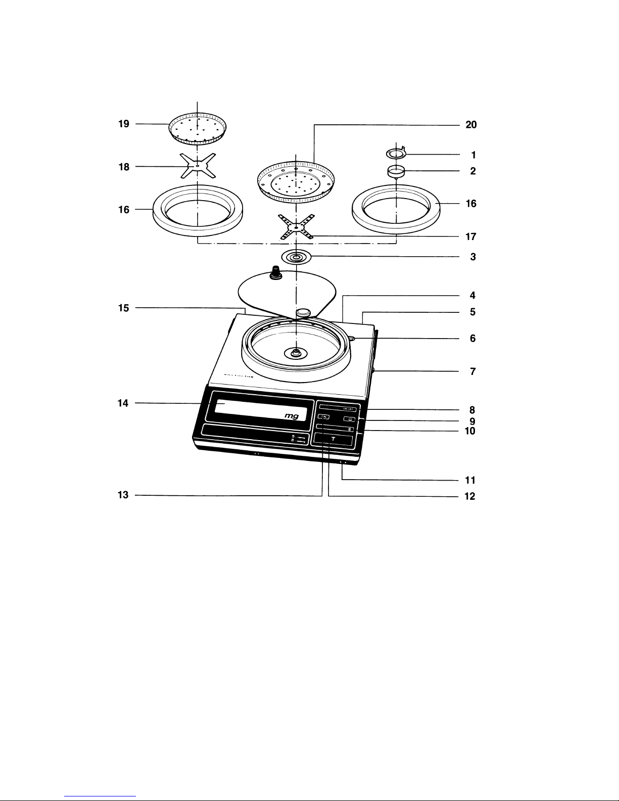
3
M3P-000V001
Filter-Microbalance
1
Weighing pan
11
Menu access switch
(for the balance operating program)
2
Pan support
12
Tare control
3
Interior draft shield
13
CAL key
4
Interface
14
Weight display
5
Power receptacle
15
Manufacturer’s label
6
Level indicator
16
Spacer
7
Leveling foot
17
Perforated filter pan holder
(for large filter weighing pan)
8
ON/OFF key
18
Filter pan holder (for small filter weighing pan)
9
Print key
19
Small filter weighing pan
10
Range expansion key
20
Large filter weighing pan

4
Contents
Page
About the Product (Warranty) 5
Storage and Shipping Conditions 6
Equipment Supplied
7
Installation Instructions
Ambient Conditions 8
Connecting Electronic Devices (Peripherals) 8
Startup
Preparing the M3P for Operation 9
Preparing the M3P-OOOV001 Filter
Microbalance for Operation 9
Connecting the Balance to Line Power 10
Voltage Selection 11
Safety Precautions 11
Leveling the Balance using the Level Indicator 11
How to Operate the Balance
General Directions for Working with the Balance 12
Weight Display 13
Turning the Balance On and Off 13
Self-Test, Weighing 14
Weighing Filters on the M3P-000V001 14
Taring, Weighing with a Tare Container 15
Below-Balance Weighing 16
Auto Zero 16
Calibration 17
Internal Calibration 17
External Calibration 18
Balance Operating Program 19
Reading a Program Menu Code (List Mode) 19
Changing a Program Menu Code (Change Mode) 19
List of the Programmable Menu Code Settings 21
Troubleshooting Guide 22
Transporting the Balance
Transport Arrestment 23
Care and Maintenance
Cleaning 24
Safety Inspection 24
Accessories
(Options) 25
Interface
26
Interfacing Devices with the Balance (RS Interface) 26
Specifications
Model M3P 27
Model M3P-000V001 28

5
About the Product (Warranty)
With this Sartorius Balance you have acquired a high-quality
electronic weighing Instrument that will ease your daily workload.
Please read these Installation and operating instructions carefully before operating your new balance.
Pursuant to the German Directive for the Implementation
of Regulations for Prevention of Accidents "Elektrische
Anlagen und Betriebsmittel (VBG 4)" [Electrical Installations and Equipment] of April 1986, it is hereby certified
that the equipment delivered, "Electronic Microbalance,
model M 3 P," is manufactured and tested in compliance
with the following DIN/VDE regulations
DIN IEC 348/VDE 0411 Safety requirements for elec-
tronic measuring apparatus DIN
IEC 380/VDE 0806 Safety of
electrically energized Office machines
DIN IEC 601/VDE 0750 Safety of medical electrical
equipment
and Article 10 of the Low Voltage Directive (73/23/EEC)
issued on February 19, 1973 by the European Community. When you use electrical equipment in installations
and under ambient conditions requiring higher safety
Standards, you must comply with the provisions as specified in the applicable regulations for installation in your
country.

6
Do not miss out on the benefits of our full warranty.
Please complete the warranty card, indicating the date of Installation, and return the card to your Sartorius dealer.
Storage and Shipping Conditions
Allowable storage temperature range: -40°C...+70°C
-40°F... 158°F
The packaging of the balance has been designed to ensure that
the balance will not be damaged even if it is dropped from a
height of 80 cm (about 32 inches).
After unpacking the balance, please check it immediately for
any visible damage as a result of rough handling during shipment. If this is the case, proceed as directed in the section entitled "Safety Inspection."
Save all parts of the packaging and the box for shipping
your balance to prevent any damage during transportation.
In addition, please disconnect all connecting cables (e.g.
the plug on the power supply) to avoid damaging them.
Do not expose the balance unnecessarily to extreme temperatures, moisture, shocks, blows or vibrations.
7
Equipment Supplied
M3P M3P-000V001
— balance
— kit of Standard
accessories
— portable
power supply
— dust cover
— Balance
— kit of Standard
accessories
— portable
power supply
— dust cover
— spacer
— 3 small filter weighing pans
(for filter diameters up
to70 mm or~ 2.8 in.)
— 3 large filter weighing pans
(for filter diameters from
70-100 mm or ~ 2.8-3.9 in.)
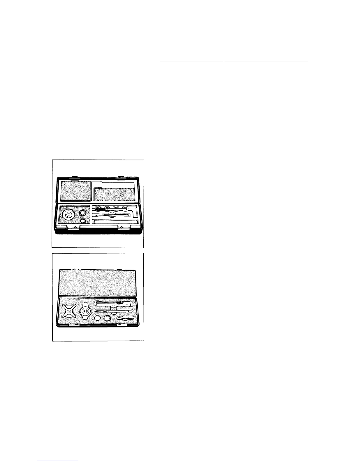
The
M3P
kit of Standard accessories contains the following:
1 weighing pan
1 pan support
1 interior draft shield
1 hanger for below-balance weighing
1 brush
1 pair of forceps
1 piece of lint-free cloth
The
M3P-000V001
kit of Standard accessories contains the
following:
1 inferior draft shield
1 filter pan holder (for the small filter weighing pan)
1 perforated filter pan holder (for the large filter weighing pan)
1 standard-size weighing pan (22 mm Ø = ~ 1")
1 pan support (for standard-size weighing pan)
1 hanger for below-balance weighing
1 brush
1 pair of forceps
1 piece of lint-free cloth
8
Installation Instructions
Ambient Conditions
Microbalances are highly precise and very sensitive measuring
Instruments. Therefore, please choose a suitable place to set
up your balance. lt should not be exposed to the following:
- Heat radiation
- Aggressive/corrosive substances
- Vibrations
- Drafts
Use a balance table or a wall console (see "Accessories") to set
up your balance.
lf you wish to move your balance to another location,
please follow the directions on page 23 under "Transporting the Balance."
Do not expose the balance to extreme moisture over long periods. Moisture in the air can condense on the surfaces of the
balance whenever a cold balance is brought to a substantially
warmer place.
lf you need to transfer the balance to a warmer area, make sure
to condition it for a few hours at room temperature. The best
way to prevent moisture condensation is to leave the balance
connected to line power. The components used in the balance
are rated to at least class KSF according to DIN 40040.
Your Sartorius Balance will provide accurate readouts even
when it is exposed to unfavorable ambient conditions.
You can adapt the balance to your requirements simply by
changing the menu code settings in the balance operating program.
For this purpose, read pages 19 through 21
Connecting Electronic Devices (Peripherals)
Turn off the balance by pressing the ON/OFF key (8)
(STANDBY state), and wait until the weighing system of the
balance has been arrested automatically for transportation (see
also "Transporting the Balance" on page 23). Unplug the power
supply before you connect or disconnect devices to or from the
interface ports.
To reduce distortion of the weight readouts caused by ambient
conditions (turbulence within the weighing chamber, for example), balance-generated data should be allowed to stabilize for
about 10 seconds before they are transmitted to an online
printer or other peripheral device.
9
Startup
Preparing the M3P for Operation
Remove the rubber band from the doors of the weighing chamber. Place the interior draft shield (3) in the weighing chamber.
Use forceps to position the pan support (2) on the draft shield,
and place the weighing pan (1) on the pan support.
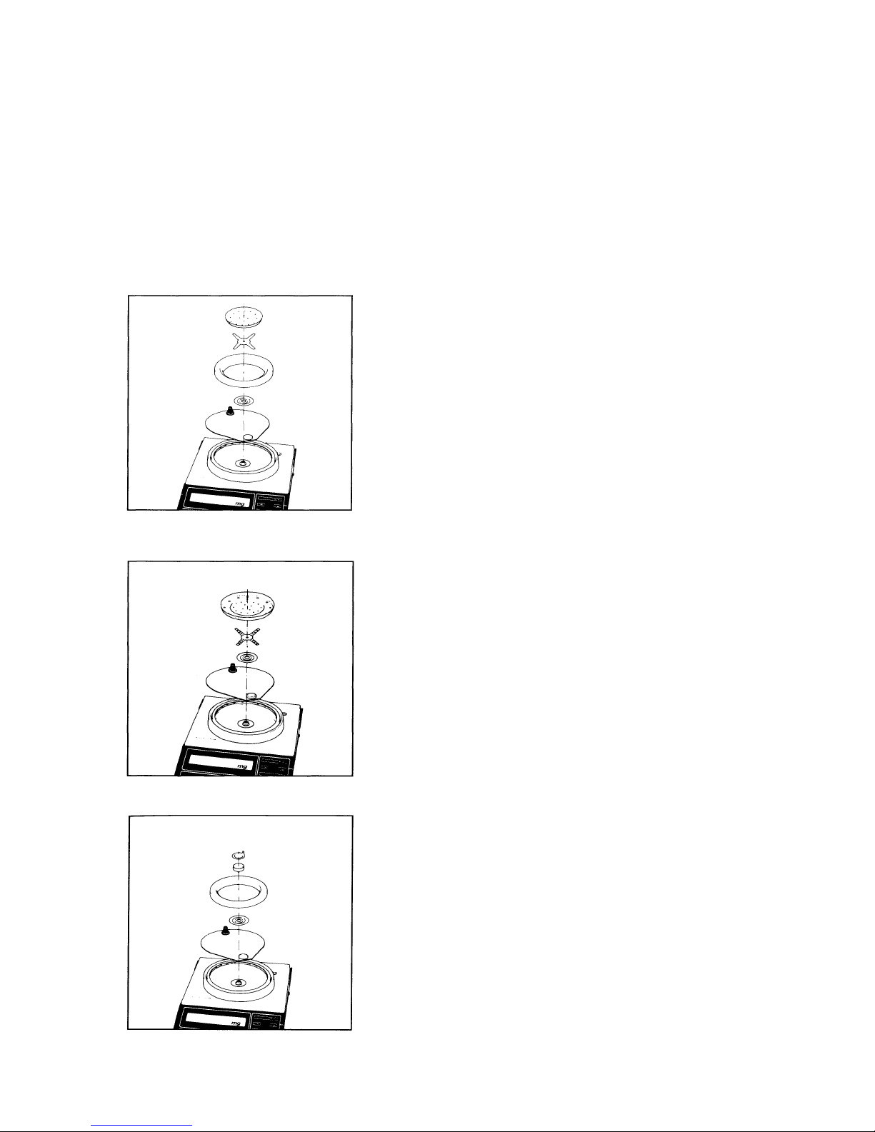
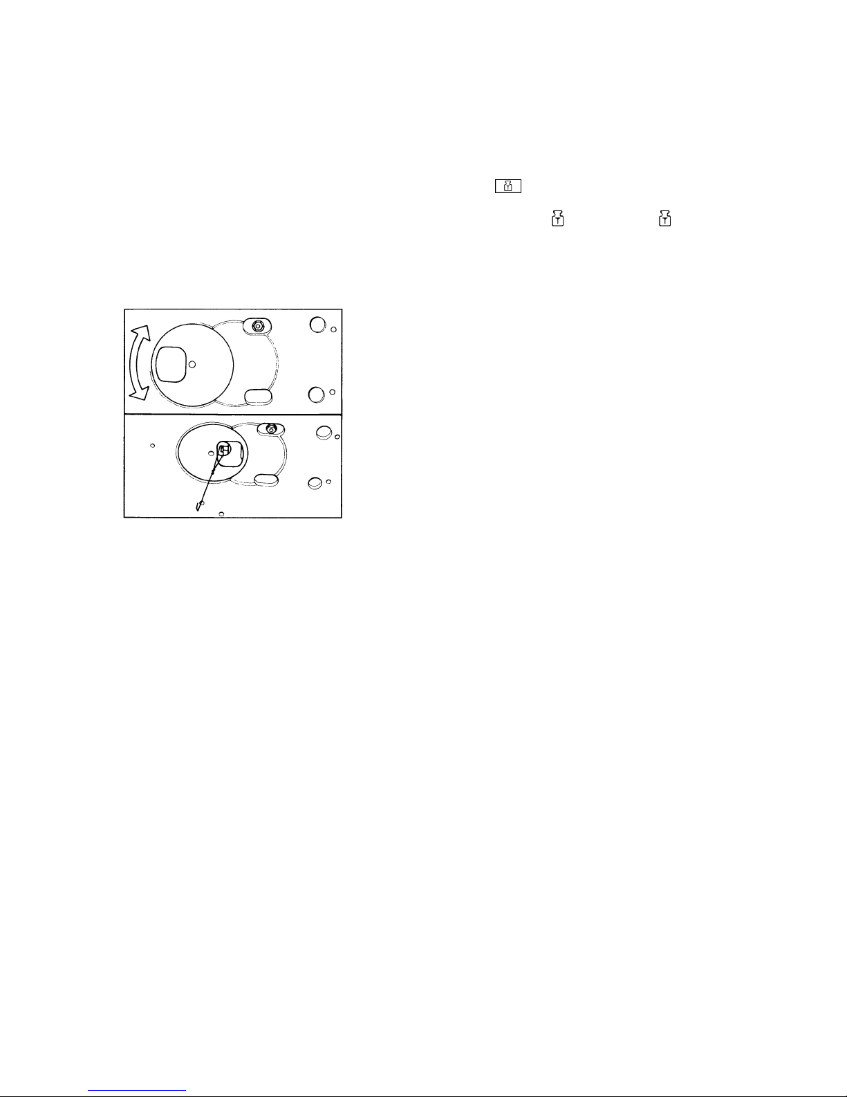
Preparing the M3P-OOOV001 Filter Microbalance for Operation
For weighing filters with diameters ranging up to 70 mm
(~ 2.8 in.):
—
Slightly lift the cover of the weighing chamber and turn it
to the left or to the right
—
Place the spacer (16) and the interior draft shield (3) in
the weighing chamber
—
Use forceps to position the filter pan holder (nonperforated) (18) and the small pan (19) for filter diameters
up to 70 mm (~ 2.8 in.)
Weighing filters with diameters ranging from 70 to 100 mm
(~ 2.8-3.9 in.):
—
Slightly lift the cover of the weighing chamber and turn it
to the left or to the right
—
Place interior draft shield (3) in the weighing chamber
—
Use forceps to position the perforated filter pan holder
(17) and the large filter weighing pan (20)
Weighing with the standard-size weighing pan
(22 mm Ø = ~ 1" Ø):
—
Slightly lift the cover of the weighing chamber and turn it
to the left or to the right
—
Place the spacer (16) and the inferior draft shield (3) in
the weighing chamber
—
Use forceps to position the pan support (2) and the standard-size weighing pan (1)

10
Connecting the Balance to Line Power
The balance is energized by a portable power supply. Make
sure that the voltage rating printed on this unit is identical to
your local line voltage rating.
lf the voltage rating specified on the power supply or the plug
design does not match the rating or Standard you use, please
contact your Sartorius dealer.
Important Note
Only use original Sartorius power supplies identified by the Sartorius label. Use of power supplies made by other manufacturers, even if these power supplies have a registered approval
rating from a national testing laboratory, requires the consent of
a certified Sartorius technician.
Plug the cord of the power supply into the power receptacle of
the balance. Secure the connection by tightening the knurled
collar.
Now plug the power supply into a wall outlet.
11
Voltage Selection
You can select the voltage only if you use our portable power
supply (69 70903) that has a European-type plug (rounded
prongs).
Safety Precautions
The power supply rated to Class 2 (double insulated) can be
plugged into a wall outlet without taking any additional safety
precautions. The pole of each Output voltage is connected to
the balance housing, which can be grounded for Operation.
The interface (see "Interfacing Devices" on page 26 in addition)
is also electrically connected to the balance housing (ground).
Leveling the Balance using the Level Indicator
At the point of use, level the balance using the leveling feet (7)
so that the air bubble is centered within the circle of the level indicator (6).

12
How to Operate the Balance
General Directions for Working with the Balance
Before you start weighing, please observe the
following:
After plugging your balance into a wall outlet
using the power supply, make sure to allow for at
least 2 hours' warmup.
Working with a microbalance requires a steady hand and a
smooth, uninterrupted technique.
Use forceps or other suitable Utensils to place your sample on
the pan.
Do a few trial weighing procedures before you begin with actual
weighing of your sample, because a weighing chamber that has
not been opened for a relatively long period may have a temperature different from that of the balance's surrounding environment. Therefore, as soon as you open the weighing chamber, a change in temperature will inevitably occur. This change
in temperature may show up as a change in the weight readout.
In this case, we recommend that before you begin with an actual repetitive weighing procedure you open and dose the
weighing chamber at the same rate as you will be doing during
such a procedure.
Carefully place your sample on the pan and, if necessary, remove it along with the pan. After the weighing chamber is
closed, the weight readout will stabilize after about 15 to 30
seconds as a rule. The accuracy of the weight readouts will increase as you perform successive weighing procedures with
greater consistency.

13
Weight Display
The weight display shows the following special
messages for your information:
BUSY
The balance processor is still busy processing a function and
will not accept any other commands to perform functions at this
time.
STANDBY
The display has been turned off with the ON/OFF key (8) and
the balance is now in the ready-to-operate mode so that it does
not require warmup.
POWER OFF
The balance was disconnected from line power (reconnection to
line power after the balance was unplugged; power failure or
outage).
CAL
The calibration function has been activated.
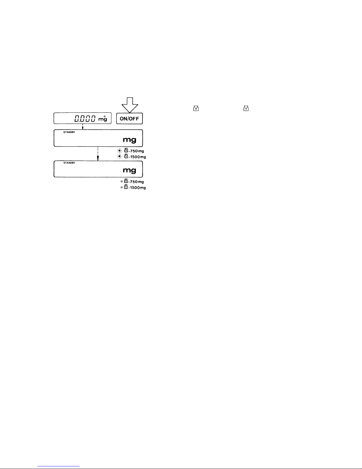
Turning the Display On and Off
Press the ON/OFF key (8) to turn the display on or off.
You can also turn it on by pressing the tare control (12).
After the balance has been connected to the power supply, the
display will go out when ever you turn off the balance using the
ON/OFF key. The LEDs next to the symbols "
~ 750 mg" and
"
~ 1500 mg" below the weight display indicate that the balance has already arrested the weighing system automatically
(see page 23 "Transporting the Balance" in addition). All other
electronic circuits will remain energized (indicated by
STANDBY). This means the balance is immediately ready to
operate without requiring warmup the next time you turn it on.

14
Self-Test
After the balance is tumed on, an automatic self-test of the
balance's electronic circuitry is performed.
This self-test ends with the readout "CH2" and will change to "L"
after about 10 seconds.
When the LED lights up next to the syrnbol "
~ 1500 mg"
below the weight display, this indicates that the balance's
weighing System has not yet been arrested.
Weighing
Press the key labeled
(10) whenever you want to Start
weighing.
The readout 0.000 mg will now be displayed.
Both LEDs next to the symbols "
~ 750 mg" and " ~ 1500
mg" will go out.
At this point, place your sample on the pan to determine the
weight and dose the weighing chamber. Do not read off the
weight in the display (14) until the small circle (above the "mg"
symbol) appears as the stability symbol. The weight readout
is stable a few seconds afterwards, as a rule.
Weighing Filters on the M3P-000V001
The M3P-000V001 filter microbalance comes with Standard filter weighing pans with an effective diameter of 73 and 105 mm
(2.9" and 4.1"), respectively, which can be used as loading
space.
Weigh filters up to 70 mm (2.8") diameters on the small pan and
filters with diameters between 70 and 100 mm (2.9" and 3.9")
on the large pan (see also "Preparing the Filter Microbalance for
Operation").
15
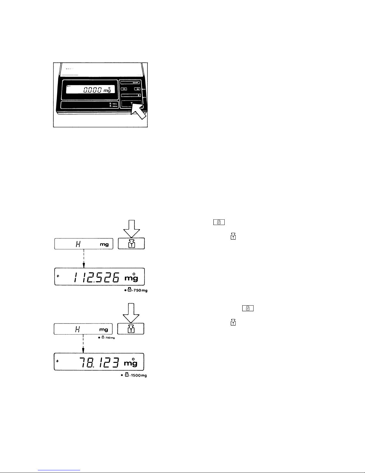
Taring
If you wish to use a Container or if the weight display does not
indicate 0.000 mg, press the tare control to zero the display.
Weighing with a Tare Container*
The balance has built-in motorized Substitution weights (tare
weights) for application of about 750 mg or 1,500 mg (accuracy
approx. 1 mg) to expand the weighing range.
lf the weight display indicates an "H," the tare Container exceeds the capacity of the 1,500 mg electronic weighing range.
Press the key labeled
(10).
The LED next to the symbol "
~ 750 mg" indicates that the
750 mg Substitution weight has been applied by motor. Now a
weighing range of 750 mg to 2,250 mg is available.
For even heavier tare Containers (overload symbol "H" in the
weight display) you can press the
key again to expand the
range.
The LED next to the symbol "
~ 1500 mg" indicates that 1,500
mg are applied by motor.
Now a weighing range of 1,500 mg to 3,000 mg is available.
Zero the display when the small circle appears above "mg"
in the weight display. Now you can weigh your sample in
the tare Container.
16
Important Note
The electronic weighing range is 1,500 mg.
Press the key labeled
again to return to the normal weigh-
ing range from the one expanded by tare weight compensation.
Both LEDs next to the symbols "
~ 750 mg" and " ~ 1500
mg" will then go out.
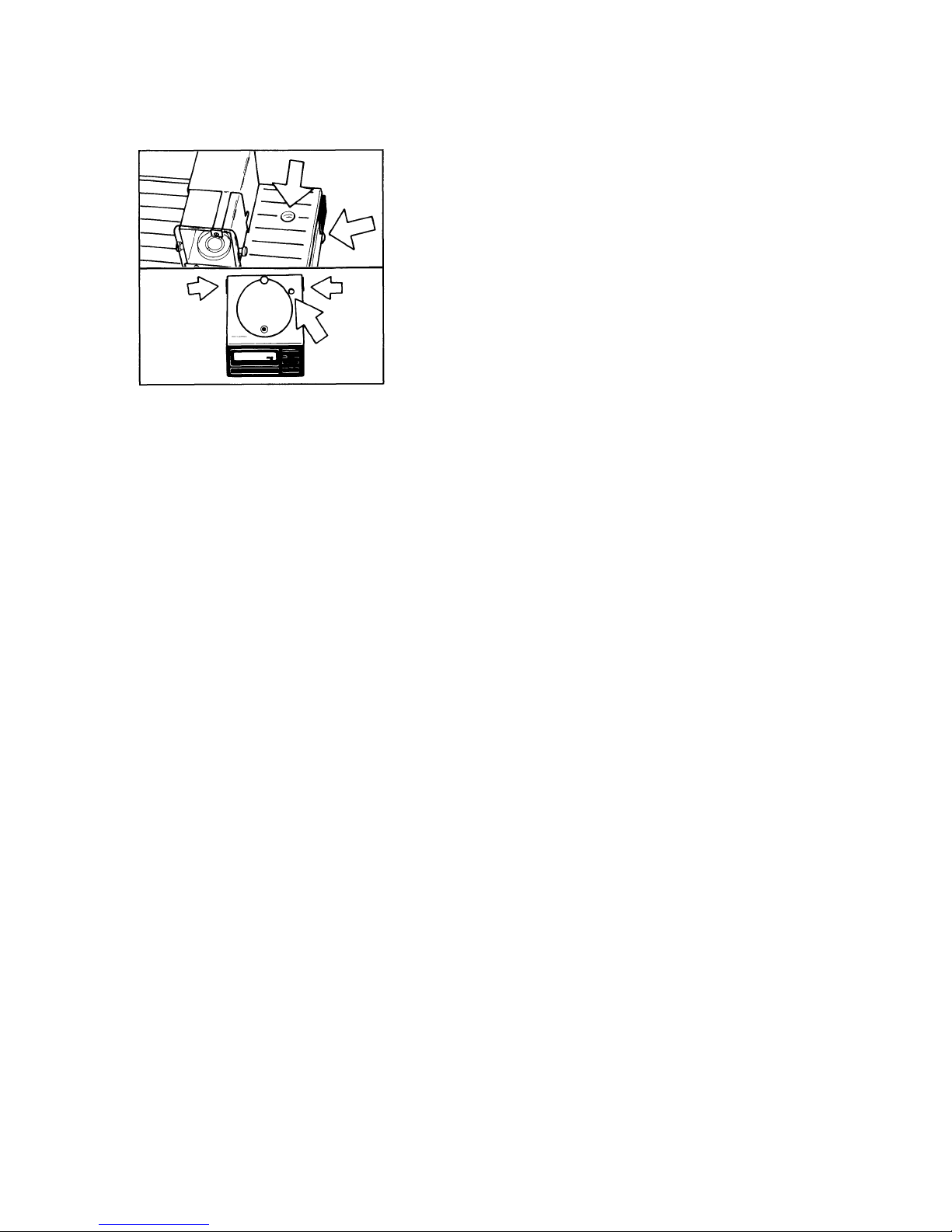
Below-Balance Weighing
A port for a below-balance weighing attachment is available on
the bottom of the balance.
Open the below-balance port by turning the closing plate. Then
attach the hanger for below-balance weighing to the hook.
Important Note
For below-balance weighing, make sure to install a special draft
shield to ensure correct readouts.
Auto Zero
This balance has an automatic zero tracking function known as
"Auto Zero" (can be turned off by menu code - see "Balance
Operating Program").
The Auto Zero function ensures that the unloaded balance will
continue to provide a zero readout (rules out most of the effects
of ambient conditions causing the readout to drift).
17
Calibration
Unload the pan and dose the weighing chamber. lf necessary,
re level the balance using the level indicator as a guide.
Internal Calibration:
The internal calibration weight conforms to accuracy class E
1
of
the International Organization of Legal Metrology (OIML).
Select the weighing range of 0 to 1500 mg (both LEDs next
to the Symbols "
~ 750 mg" and " ~ 1500 mg" go out).
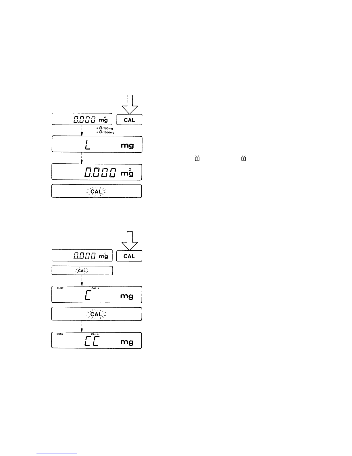
Press the CAL key (13). "CAL" will now be displayed below the
weight readout.
Remove both Substitution weights. "L” is now displayed on the
balance. Afterwards, place the weights back on the pan. The
weight readout is displayed again.
Zero the display and press the CAL key (13) again when the
display shows a zero readout. The weight display now
indicates "C."
lf "CE" is displayed instead, zero the display and press the
CAL key again.
After a few seconds, "CC" will be displayed followed by 0.000
mg. An acoustic Signal indicates the end of the calibration procedure.
Important Note!
While calibration is in progress, indicated by "C" or "CC" in the
display, do not press any key.
However, should you do so by mistake, just turn the balance off,
then on again with the ON/OFF key. Following this, repeat calibration.
18
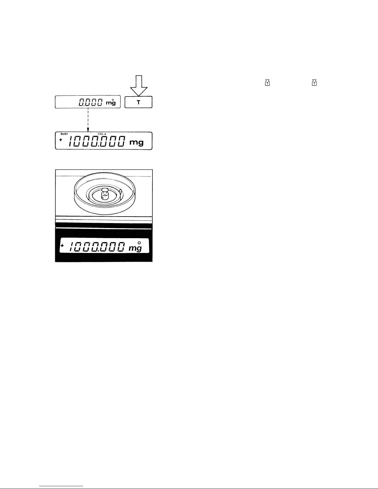
External Calibration:
Unload the weighing pan. Select the 0 to 1500 mg weighing
range (both LEDs next to the Symbols "
~ 750 mg" and " ~
1500 mg" go out). As soon as you obtain a zero readout, press
the tare control (12) for at least 3 seconds until the calibration
weight readout appears in the weight display (14).
Center the calibration weight of the desired accuracy class on
the weighing pan and dose the weighing chamber.
A circle is now displayed above the "mg" symbol. An acoustic
signal indicates the end of the calibration procedure.
Open the weighing chamber and remove the calibration weight
from the weighing pan.
You can block access to both the infernal and external calibration functions - to find these menu codes, refer to the "Balance
Operating Program."
These functions are accessible whenever the balance operating
program has been unlocked using the menu access switch (11).

19
Balance Operating Program
The balance operating program lets you adapt your balance to
various ambient conditions and application requirements.
At the factory, we have set the codes for a Standard program
which is protected by a locking function to prevent accidental
changes.
The "menu code" contains the information of the operating program, lt consists of three digits, known in "computerese" as the
page (1st digit), the line (2nd digit) and the word (3rd digit).
Reading a Program Menu Code (List Mode)
How to access the menu of the balance operating program:
With the display turned off (STANDBY state), hold down the
tare control (12) and briefly press the ON/OFF key (8). Once the
display indicates "CH2," release the tare control. The Status of
the balance operating program will be indicated in the weight
display at the end of the automatic self test:
"L” Stands for the list mode. In this mode, you can read a menu
code setting, but you cannot change it.
Changing a Program Menu Code (Change Mode)
lf you wish to change a program menu code, you must first
unlock the menu access switch to access the program menu.
To do so, remove the protective cap located on the front right of
your balance, and slide the menu access switch (11) in the direction of the arrow. The display will indicate "C," which Stands
for the change mode, meaning you can now change a menu
code setting.

20
After you have accessed the menu of the operating program,
the display will show a continuous sequence of numbers from 05 for the "page" or first digit of the code, in addition to the Status
code letter "L' or "C".
When the first digit of the code you wish to check or change appears, press the fare control (12). The "page" code number (1st
digit) now stops in the display, and a series of numbers for the
2nd digit or "line" will begin to cycle. Press the tare control again
to stop the code number of your choice in the display. Next, the
numbers for the "word" (last digit) will cycle in the display. Repeat the procedure to enter the last digit of the code.
The "o" symbol that appears indicates the actual setting.
To change any menu code settings ("C" mode), press the tare
control as soon as the appropriate numeric code is displayed.
Brief display of BUSY and the "o" symbol confirms your selection, followed by a return to "zero" for the 2nd digit or "line."
How to return to the weighing mode:
Press the tare control each time a 0 appears in the numerical
sequence (word, line, page). lf you have changed a menu code,
it will be stored as soon as the display returns to the weighing
mode and 0.000 mg is indicated.
Lock the balance operating program using the menu access
switch and replace the protective cap.
21
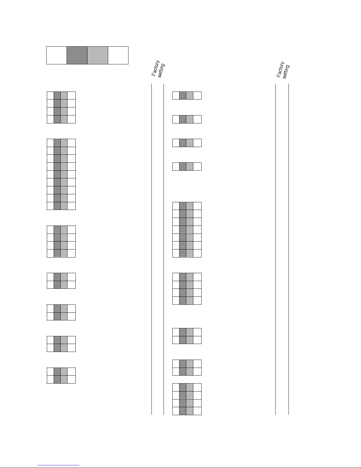
List of the programmable Menu Code Settings
C 1 3
1
Page
1
st
digit
line
2nd digit
Word
3rd digit
Code
Ambient Conditions
Code
Data Output parameter
C 1 1 1
Very stable
!
C 2 1 1
Output upon external
C 1 1 2
Stable
print command,
C 1 1 3
Unstable
regardless of stability
"
c 1 1 4
Very unstable
C 2 1 2
Output upon external
!
print command,
Code
Stability Range
at stability
C 1 2 1
0,25 digit
C 2 1 3
Automatic output
C 1 2 2
0,5 digit
"
synchronous with display,
C 1 2 3
1 digit
"
regardless of stability
C 1 2 4
2 digits
"
C 2 1 4
Automatic output
C 1 2 5
4 digits
"
synchronous with display,
C 1 2 6
8 digits
"
at stability
C 1 2 7
16 digits
"
C 1 2 8
32 digits
"
Code
Baud Rate
C 1 2 9
64 digits
!
C 2 2 1
150 Bd
C 2 2 2
300 Bd
Code
Display Format
C 2 2 3
600 Bd
C 1 3 1
Last decimal ON
C 2 2 4
1200 Bd
!
C 1 3 2
Last decimal OFF
c 2 2 5
2400 Bd
C 1 3 3
Last decimal at stability
c 2 2 6
4800 Bd
C 1 3 4
All decimals at stability
c 2 2 7
9600 Bd
!
Code
Tare Parameter
Code
Parity Bit
C 1 4 1
Without stability
c 2 3 1
Mark parity
C 1 4 2
At stability
c 2 3 2
Space parity
c 2 3 3
Odd parity
!
Code
Auto Zero
C 2 3 4
Even parity
C 1 5 1
ON
C 1 5 2
OFF
!
Special Information
Code
Program Lock
Code
External Calibration
C 4 1 1
OFF
C 1 6 1
Accessible
!
C 4 1 2
ON
!
C 1 6 2
Access blocked
Code
Acoustic Signal
Code
Internal Calibration
C 4 3 1
ON
C 1 7 1
Accessible
!
C 4 3 2
OFF
!
C 1 7 2
Access blocked
C 4 3 0
Call Program Line
C 4 0
Call Program Page
!
C 0
End of Programming
Additional Parameters for the data Output format at the interface port and for calculation programs are available on request.-Please refer to the “Accessories."

22
Troubleshooting Guide
Problem ... Causes ... Remedy
No segments appear in the weight
display (14)
-
No line current available
-
The power supply is not plugged
in
-
Check power supply
-
Plug in power supply
Weight display only shows "L' or
"CH 2"
-
The weighing system is still arrested for transportation
-
The weighing pan (1) or the pan
support (2) is not in place
-
One or both of the Substitution
weights are applied to expand
the range
-
A Substitution weight is stuck
-
Press the key labeled
(10)
-
Position the pan and pan support
-
Press the
key
-
Contact the Services Division or
Dept
Weight display shows "H"
-
Sample exceeds the 1,500 mg
capacity of the electronic weighing range
-
Sample exceeds maximum loading capacity of the balance
-
Press the
key
(10)
(see
“Weighing with a Tare Container”)
-
Unload the weighing pan
The weight readout changes constantly or the special message
"BUSY" does not go out in the
weight display
-
Unstable ambient conditions
-
Too much Vibration or the balance is exposed to a draft
-
The weighing chamber is not
completely closed
-
The closing plate of the attachment for below-balance weighing
is open
-
The area surrounding the weighing pan is not clean (e.g. lint)
-
The sample does not have a
stable weight (absorbs moisture
or evaporates)
-
Set up the balance in another
area
-
Access the menu to adapt weighing environment
-
Close of the weighing chamber
-
Turn the plate to close the port at
the base for the below-balance
-
weighing attachment
-
Clean area
Weight display shows "CE"
-
The CAL key (13) has not been
pressed when the display indicated zero
-
The weighing pan is loaded
-
Press the tare control (12) and
re-press the CAL key
-
Unload the weighing pan
The special code "CC" does not go
out in the weight display
-
The balance is not ready to calibrate or is in the warmup phase
-
The weighing System is affected
by a draft or vibrations
-
The closing plate of the attachment for below- balance weighing is open
-
After plugging in the balance
using the power supply, allow for
at least 2 hours' warmup
-
Set the appropriate code by accessing the menu of the operating program
-
Turn the plate to dose the port at
the base for the below-balance
weighing attachment
The weight readout is obviously
wrong
-
The balance has not been calibrated
-
The balance has not been tared
before weighing)
-
The air bubble of the level indicator (6) is not with in the circle
-
Calibrate the balance
-
Tare before weighing
-
Level the balance
23
Transporting the Balance
To transport the balance, the weighing system must be arrested
as described in the following.
Transport Arrestment
Before you unplug the balance from the power supply, turn
off the balance using the ON/OFF key (8). The LEDs next to
the symbols "
~ 750 mg" and " ~ 1500 mg" below the
weight display will now light up, indicating that the weighing system of the balance is being arrested automatically
for transportation. As soon as the LED's go out, automatic
arrestment of the weighing system has been completed.
Remove the weighing pan (1) or the filter pan (19/20). Use your
fingers to carefully lift the interior draft shield (3) along with the
assembled pan support (2) or filter pan holder (17/18) out of the
weighing chamber. Disassemble the parts and replace then in
the case for the kit of accessories.
Place a rubber band over both knobs of the weighing chamber
doors to prevent then from sliding open when the balance is
transported.
The balance must be conditioned each time you move it to
another location.

24
Care and Maintenance
Cleaning
Please do not use any aggressive cleaning agents (solvents or
similar agents). Instead, use a piece of cloth wet with a mild detergent to clean the balance.
Make sure that no liquid enters the balance housing.
After cleaning, wipe down the balance with a soft, dry piece of
cloth.
Safety Inspection
lf there is any indication that safe Operation of the balance is
no longer warranted, turn off the power and unplug the balance
immediately. Lock the equipment in a secure place to ensure
that it cannot be used for the time being.
In this case, notify the Sartorius Technical Services Dept. or Division. Only certified Sartorius service technicians who have the
proper manuals are allowed to perform maintenance and repair
work on the balance.
Safe Operation of the balance with the power supply is no
longer ensured when
—
there is visible damage to the power supply
—
the power supply no longer functions properly
—
the power supply has been stored for relatively long periods
under unfavorable conditions
—
the power supply has been exposed to rough handling during shipment
We recommend that the balance with the power supply be inspected according to the following checklist by a qualified Sartorius Service technician:
—
Leakage current <0.05 mA measured by a properly calibrated multimeter
—
Insulation resistance >7 M
Ω
measured with a constant volt-
age of at least 500 V at a 500 k
Ω
load
The duration and number of measurements should be determined by a qualified Sartorius service technician according to
the particular ambient and operational conditions. However,
such inspection must be done at least once a year.

25
Accessories (Options)
Data printer with
date/time and statistics functions
YDP 02-0DV1
Print speed approx. lines/sec
1,5
Printer housing (W x D x H)
in mm
in inches
150 x 138 x 43
5.5 x 5.4 x 1.7
Tare foot switch 7252
Carrying case YDB 01 M
Antitheft locking device 6087
Balance table YWT 01
Extension with 2 drawers for
balance table
6802
Wall console 6804
Digital/analog converter YDA 01 Z
IEC converter 7253 16
RS 422 converter 7253 19
Dust cover for MP3 6960 M150
Dust cover for M3P-000V001 6960 M151
26
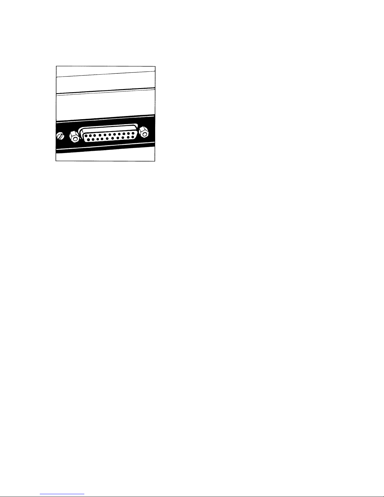
Interface
See the "Interface Description for Sartorius Balances and
Scales" enclosed.
Interfacing Devices with the Balance
(RS Interface)
Make sure that the interface port is electrically connected to the
protective grounding conductor of the balance housing. The cabling supplied as accessory components is shielded and electrically connected on both ends to the cases of the connectors.
This electrical connection may result in interference caused by
cables scraping the floor or by transient currents if you have
grounded the housing or connected the protective grounding
conductor for line power. If necessary, connect an equipotential
bonding conductor to the balance.

27
Specifications
Model M3P
Electronic weighing range mg 500/1,000/1,510 (Poly Range)
Maximum loading capacity mg approx. 3,000
Readability mg 0,001/0,002/0,005 (Poly Range)
Tare range (by subtraction) mg approx. –3,000
Standard deviation
(corrected for drift, typical*)
mg
≤
±0,001/0,002/0,003
Max. linearity mg
≤
±0,002/0,004/0,005
Stabilization time (typical) s 10
Display update s 0,1 – 0,8 (selectable)
Adaption to ambient conditions
and application requirements
By selection of 1 of 4 optimized filter levels
Stability range d 0,25 ... 64 (selectable)
Ambient temperature range
o
C +15 to +30 (59oF to 86oF)
Sensitivity drift within 290 … 300 K /K
≤
±5∙10
-6
Deviation of the readout when the
balance is tilted 1:1000
mg
≤
±0,03
Pan size mm Ø 22 (about 1 inch)
Balance housing (W x D x H)
mm
inches
219 x 291 x 137,5
8.6 x 11.5 x 5.4
Weighing chamber (W x D x H)
mm
inches
54 x 49,5 x 53,5
2.2 x 1.9 x 2.1
Net weight, approx. kg 5,2 (approx. 11.4 lbs.)
Power requirements
(voltage + frequency: 50 – 60 Hz))
115 or 230 V depending on the power supply used
Allowable voltage fluctuation -20% ... +15%
Power consumption VA max. 13 (typical)
Interface
RS 232 C/V24 – 28, RS 423/V10; 7-bit;
parity: even, mark, odd, space;
transmission rate 150 ... 9,600 Baud
* for samples or objects that are not or only slightly electro statically charged

28
Specifications
Model M3P-000V001
Electronic weighing range mg 500/1,000/1,510 (Poly Range)
Maximum loading capacity mg approx. 3,000
Readability mg 0,001/0,002/0,005 (Poly Range)
Tare range (by subtraction) mg approx. –3,000
Standard deviation
(corrected for drift, typical*)
mg
≤
±0,002/0,003/0,004
Max. linearity mg
≤
±0,002/0,004/0,005
Stabilization time (typical) s 15
Display update s 0,1 – 0,8 (selectable)
Adaption to ambient conditions
and application requirements
By selection of 1 of 4 optimized filter levels
Stability range d 0,25 ... 64 (selectable)
Ambient temperature range
o
C +15 to +30 (59oF to 86oF)
Sensitivity drift within 290 … 300 K /K
≤
±5∙10
-6
Deviation of the readout when the
balance is tilted 1:1000
mg
≤
±0,03
Pan size mm 105/73/22 (~4”/3”/1”)
Balance housing (W x D x H)
mm
inches
219 x 291 x 98
8.6 x 11.5 x 3.9
Weighing chamber (Dia. x H)
Diameter depends on the choice of filter weighing pan: for
105 mm pan: 117 mm (4.6”)
for 73 and 22 mm pans: 85 mm (3.3”)
Effective height for all versions: 11 mm (.43”)
Net weight, approx. kg 5,4 (approx. 11.9 lbs.)
Power requirements
(voltage + frequency: 50 – 60 Hz))
115 or 230 V depending on the power supply used
Allowable voltage fluctuation -20% ... +15%
Power consumption VA max. 13 (typical)
Interface
RS 232 C/V24 – 28, RS 423/V10; 7-bit;
parity: even, mark, odd, space;
transmission rate 150 ... 9,600 Baud
* for samples or objects that are not or only slightly electro statically charged


Sartorius AG
B 37070 Göttingen
P Weender Landstraße 94–108, 37075 Göttingen
T (0551) 308-0, F (0551) 308-3289
Internet: http://www.sartorius.com
Copyright by Sartorius AG, Göttingen, Deutschland.
All rights reserved. No part of this publication may be
printed or translated in any form or by any means without
the prior written permission of Sartorius AG.
Sartorius AG reserves the right to make change to the
technology, features, specification and design of the equipment
without notice.
 Loading...