

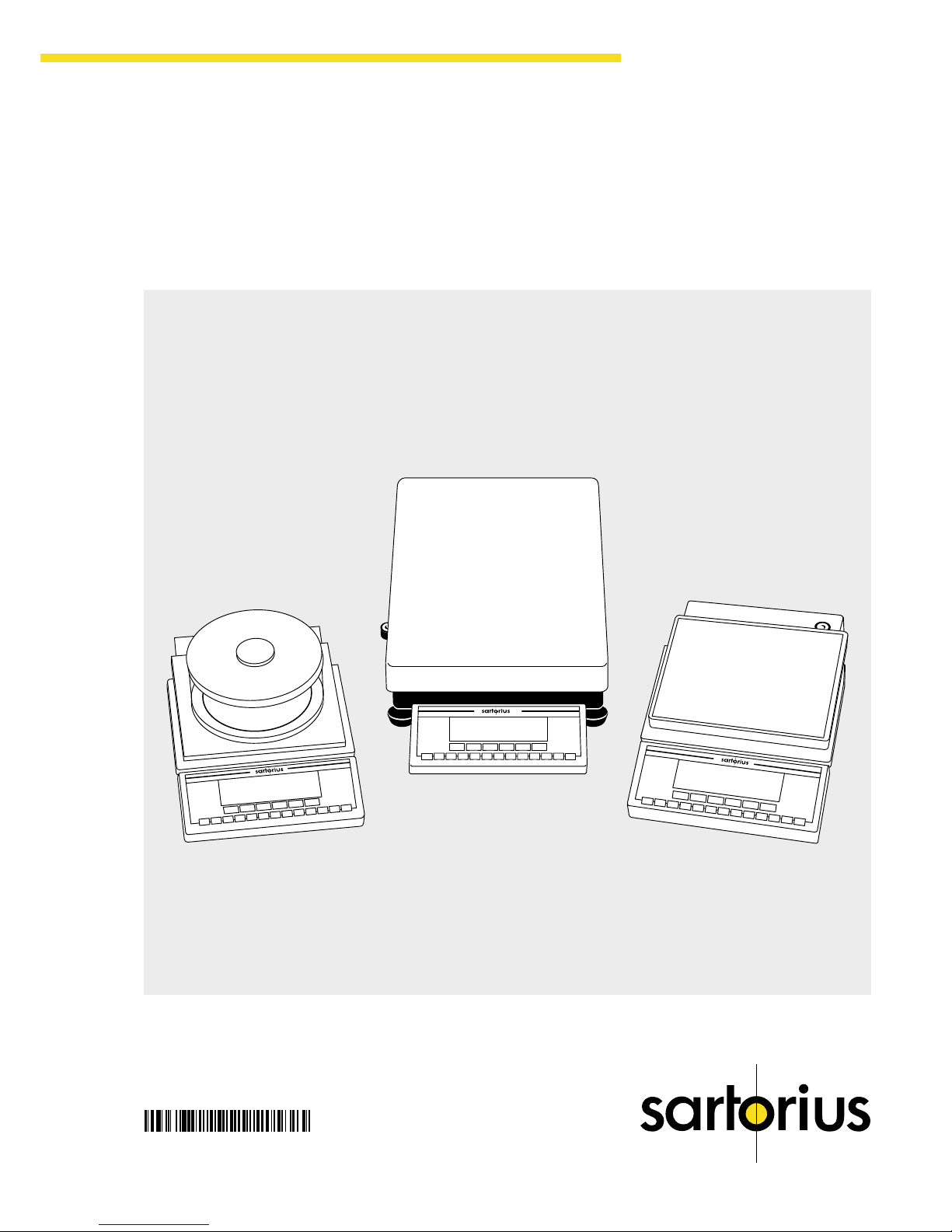
Sartorius LP Models Operating Instructions Manual
1
Getting Started
Sartorius Master
pro
Series
LP Models
Electronic Precision Balances
Operating Instructions
98648-006-26

2
Intended Use
The Master
pro
Series from Sartorius
offers precision balances with
capacities ranging from 1 to 64 kg
for measurement of mass. A broad
range of special performance
features make the Master
pro
balances
ideal for use as measuring and test
equipment in ISO or GLP quality
management systems. These features
include:
– Fully automatic self-calibrating
and adjustment function, isoCAL
(time- and temperature-dependent)
– reproTEST for quick determination
of the standard deviation to check
the reproducibility of results
– ISO/GLP-compliant recording
capability for printouts
– Password-protected menu lock
Master
pro
balances meet the highest
requirements on the accuracy and
reliability of weighing results through
the following features:
– Efficient filtering-out of vibration
– Stable and reproducible results
– Excellent readability under any
lighting conditions
– Rugged, durable weighing system
Master
pro
balances save
work and speed up simple routine
applications through:
– Ultrafast response times
– Built-in applications
(counting, animal weighing,
weighing in percent, etc.)
– Automatic initialization when you
switch on the balance
– Easy input of alphanumeric
sample, lot and balance IDs
– Flexible, easy-to-use display and
control unit
– Connectivity for control through
an on-line computer
Contents
Intended Use .............................2
Contents .................................. 2
Warnings and
Safety Precautions ..................... 2
Operating Design ...................... 3
Getting Started ......................... 5
Configuring the Balance
Setting the Language ............. 10
’Info’ Display ........................ 10
Entering User Data (Input) ....... 11
Setting Parameters (Menu) ...... 14
Operating the Balance
Basic Weighing Function........ 21
Calibration/Adjustment .......... 24
ReproTEST ........................... 30
Application Programs
Toggle between
Weight Units ........................ 31
Counting ............................. 33
Weighing in Percent .............. 36
Net-Total Formulation ............. 40
Animal Weighing.................. 42
Checkweighing .................... 46
Recalculation ........................ 51
Data Output Functions ............ 56
Pin Assignment Chart ............. 68
Cabling Diagram .................. 69
Additional Functions .............. 70
MP8 Interface Emulation ......... 72
Error Codes ............................ 73
Care and Maintenance............. 75
Instructions for Recycling .......... 76
Overview
General Views
of the Balances ..................... 77
Description of the Keys ........... 80
Menu Structure ..................... 81
Specifications ....................... 82
Accessories (Options)............. 88
Declaration of Conformity ....... 90
EC Type-Approval Certificates .. 93
Plates and Markings .............. 96
Index .................................. 97
Appendix
Entering the User Password
Warnings and
Safety Precautions
This balance has been constructed
in accordance with the European
Directives as well as international
regulations and standards for
operation of electrical equipment,
electromagnetic compatibility, and
stipulated safety requirements.
Improper use or handling, however,
can result in damage and/or injury.
Read these operating instructions
thoroughly before using your
balance to prevent damage to the
equipment. Keep these instructions
in a safe place.
Follow the instructions below
to ensure safe and trouble-free
operation of your balance:
! Do not use this balance
in a hazardous area/location
! Make sure that the voltage rating
printed on the AC adapter is
identical to your local line voltage
– The only way to switch the power
off completely is to disconnect the
AC adapter
– Type of protection for the housing:
– LP64001S, LP34001S,
LP16001S, LP34001P and
LP34000 meet IP44
requirements
– Additional balances with a
readabilty ≥ 1 mg comply
with IP54
– AC adapters meet IP20
requirements
– Protect the AC adapter from
contact with liquid
– Connect only Sartorius accesso-
ries and options, as these are
optimally designed for use with
your Master
pro
balance
When cleaning your balance,
make sure that no liquid enters the
balance housing; use only
a slightly moistened cloth to clean
the balance.
Do not open the balance housing.
If the seal is broken, this will result in
forfeiture of all claims under the
manufacturer’s warranty.
In case you have any problems with
your balance:
k contact your local Sartorius
office, dealer or service center

3
Getting Started
Operating Design
The balances in the Master
pro
Series consist of a weighing cell
and a display and control unit.
In addition to the choice of power
supply (via AC adapter or external
rechargeable battery pack), your
balance also has an interface port
for connecting a printer, computer or
universal remote control switch.
The display and control unit and the
weighing cell can be set up
separately. Operation of Master
pro
balances follows a uniform
“philosophy” which is described in
this manual.
Keys
The functions used most often
are assigned to their own specific
keys. There are additional
keys for assignment of other (multiple)
functions, in some cases
dependent on the current operating
status (so-called “soft keys”).
Each key is described in detail in
the chapter entitled “Overview.”
Normal Operation
In the operating mode, these four
keys function as c, q, w and
v keys.
Setup Mode
In the setup mode, these keys
take on the function of arrow keys
(x y Y X).
Soft Key Mode
The ‘soft key’ functions depend on
the current operating status; the
current function is indicated in the
text line of the display. In this
example, the soft keys are used to
access Info, Menu and Input
functions.
info--menu--input
Display
The display is divided into six
sections:
– Line for metrological data:
Metrological specifications of the
weighing platform.
Max ...g d=...g
Display during use as a legal
measuring instrument:
Max ...g Min ...g e=...g d=...g
– Bar graph: Display in percent of
the weight on the balance relative
to the maximum capacity and for
over/under checkweighing
– Measured value line:
Display of weight readout or
alphanumeric input
Important Note Concerning
Verified Balances Approved for
Use as Legal Measuring
Instruments in the EU*:
For verified balances that have
a verification scale interval “e”
which is greater than the scale
interval “d,” the last digit on the
display is bordered.
– Weight unit display:
Weight unit, other unit of measure,
operating information
The G symbol indicates nonverified weight values.
– Symbol display:
Indicates operating status;
application selected
– Text line: Prompts for operator
guidance, soft key designations
See the “Data Output” section
in the chapter entitled “Operating
the Balance” for a detailed
description of the information
displayed in each of these sections.
* including the Signatories of
the Agreement on the European
Economic Area
Operating Design

4
Input
Numeric Input
To enter numbers:
Press the 1 2 … 0 . keys
To store numbers entered:
Press the soft key
To interrupt/cancel numeric input:
Press c
Alphabetic Input
To enter letters:
First press the a key, then press
a letter soft key (Y or y)
repeatedly until the desired letter
or special character is displayed in
the text line
To store a word entered:
Press the soft key
To interrupt/cancel alphabetic input:
Press c
Configuring Balance Operating
Parameters
To set parameter options for
configuring your balance, you can
select the desired parameters from
a list. The lists of parameter options
comprise a menu, which has
three levels.
For configuration functions:
Press the M key; then press the
menu soft key
To move within a menu level:
Press Y or y
To change to another menu level:
Press x or X
To confirm the selected parameter
setting in the 3rd menu level:
Press X
“o” indicates the currently set
parameter
Additional information is displayed
in the text line. See the chapter
entitled “Configuring the Balance”
for a detailed description of all
parameter settings.
To save setting and exit menu:
Press M
To interrupt the parameter setting
process without saving changes:
Press e
Data Output
Your Master
pro
balance is equipped
with a data interface for connecting
your choice of the following:
– Printer
– Peripheral device (e.g., computer)
– Universal remote control switch
Printer
You can configure the print
functions to meet your individual
requirements by selecting the
corresponding menu code.
You can have printouts generated
automatically, or by pressing p;
dependent on or independent of the
stability or time parameters; with
or without IDs; and as standard or
ISO/GLP-compliant printouts.
ISO: International Organization
for Standardization
GLP: Good Laboratory Practice
See the section on “Data Output
Functions” in the chapter entitled
“Operating the Balance” for
a detailed description of data output
options.
Interface Port
Instead of a printer, you may choose
to connect a different peripheral
device, e.g. a computer (PC). With
an on-line PC you can control both
the weighing cell and the display
unit of the Master
pro
balance.
Request messages are sent
via the interface to initiate functions
in the weighing cell and in the
display unit. Some of the functions
generate response messages.
See the section on “Data Output
Functions” in the chapter
entitled “Operating the Balance”
for a detailed description of the
interface port.
Error Codes
If you press a key that has no
function, or which is blocked
at a certain point in an application
program, this error is indicated
as follows:
– a double-beep is sounded as an
acoustic signal, and
– where necessary, a message is
displayed for 2 seconds in the text
line, after which the text line
returns to the previous display.
The response to an operator error
is identical in all models of the
Master
pro
series. See the chapter
entitled “Error Codes” for a detailed
description.
Storing Settings
Storing Parameter Settings
The settings configured are
stored in the balance’s non-volatile
memory. The most recent
parameter settings are active when
you switch on the balance.
Saving Parameter Settings
You can assign passwords
in order to block access to the
“Menu” and “Input” functions.

5
Getting Started
Getting Started
Warranty
Do not miss out on the benefits of our
full warranty. Complete the warranty
registration card, indicating the date
of installation, and return the card
to your Sartorius office or dealer.
Storage and Shipping
Conditions
Allowable storage temperature:
0 °C …+40 °C (+32°F …+104°F)
The packaging has been designed
to ensure that the balance will not be
damaged even if it is dropped from
a height of 80 centimeters (about
31 inches). Do not expose the
balance to extreme temperatures,
blows, shocks, vibration or moisture.
Unpacking the Balance
● After unpacking the balance,
check it immediately for any
visible damage as a result of
rough handling during shipment.
k If this is the case, proceed
as directed in the section on
“Safety Inspection” in the chapter
entitled “Care and Maintenance.”
It is a good idea to save the box
and all parts of the packaging until
you have successfully installed your
balance. Only the original packaging provides the best protection
for shipment. Before packing your
balance, unplug all connected cables
to prevent damage. The cardboard
strips between the display and
control unit and the weighing
platform are part of the protective
packaging for shipment!
LP balances with a capacity ≥ 16 kg
– Balance with display and
control unit
– AC adapter
– Weighing pan
Installation Instructions
The Sartorius Master
pro
balances
are designed to provide reliable
weighing results under normal
ambient conditions in the laboratory
and in industry. When choosing
a location to set up your balance,
observe the following so that you will
be able to work with added speed
and accuracy:
– Set up the balance on a stable,
even surface
– Avoid placing the balance
in close proximity to a heater or
otherwise exposing the balance to
heat or direct sunlight
– Protect the balance from
drafts that come from open
windows or doors
– Avoid exposing the balance
to extreme vibrations during
weighing
– Protect the balance from aggres-
sive chemical vapors
– Do not expose the balance
to extreme moisture
Conditioning the Balance
Moisture in the air can condense
on the surfaces of a cold balance
whenever it is brought into a substantially warmer place. If you transfer
the balance to a warmer area, make
sure to condition it for about 2 hours
at room temperature, leaving it
unplugged from AC power.
Afterwards, if you keep the balance
connected to AC power, the
continuous positive difference in
temperature between the inside
of the balance and the outside will
practically rule out the effects
of moisture condensation.
Equipment Supplied
The equipment supplied includes the
components listed below:
LP balances with a readability of 1 mg
– Balance with display and
control unit
– AC adapter
– Dust cover
– Shield disk
– Pan support
– Weighing pan
– Glass draft shield cylinder
– Draft shield cover
LP8200S, LP8200P, LP 6200S,
LP 4200S, LP 2200S, LP 820, LP 420,
LP 2200P, LP 5200P
– Balance with display and
control unit
– AC adapter
– Dust cover
– Pan draft shield
– Weighing pan
LP 12000S, LP 6200,
LP 4200, LP 2200, LP 12000P
– Balance with display and
control unit
– AC adapter
– Dust cover
– Weighing pan
Important Note Concerning
Verified Balances Approved for
Use as Legal Measuring Instruments in the EU*:
Provided that an official seal is
required for the verified balance,
a control seal is affixed to the
balance. This seal will be irreparably damaged if you attempt to
remove it. If the seal is broken,
the validity of the verification will
become void, and you must have
your balance re-verified.
* including the Signatories
of the Agreement on the European
Economic Area
6
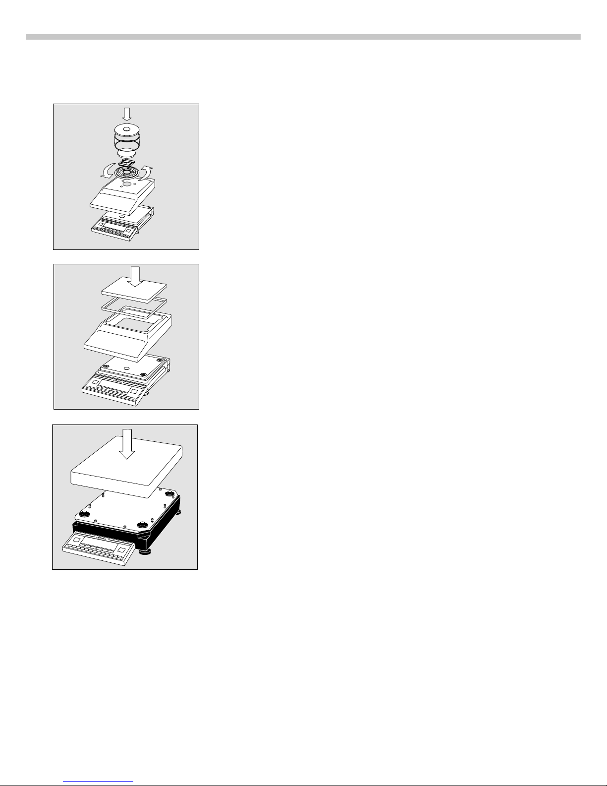
Setting Up the Balance
Preparing Balances with a Round Glass Draft Shield
● Place the components listed below on the balance in the order given:
– Dust cover
– Shield disk; turn counter-clockwise until it stops and is secured
– Pan support
– Weighing pan
– Glass draft shield cylinder
– Draft shield cover
Preparing Balances with a Rectangular Weighing Pan
and a Weighing Capacity ≤ 12 k g
● Place the components listed below on the balance in the order given:
– Dust cover
– Pan draft shield (depending on the model)
– Weighing pan
Preparing Balances with a Rectangular Weighing Pan
and a Weighing Capacity ≥16 kg
● Place the weighing pan on the balance

7
Getting Started
Separate Operation of the Display Unit
● Turn the balance upside down and lay it on a padded surface
to avoid damage to the weighing system.
● Use a screwdriver to remove the 2 screws from the display unit retainer
● Remove the display unit
> Cable lengths
– LP balances with a weighing capacity ≤ 12 kg: 55 cm
– LP balances with a weighing capacity ≥ 16 kg: 80 cm
k See the chapter entitled “Accessories” for information on longer cables
k If you wish to use a longer cable, it must be installed by an authorized
Sartorius service technician
Options for Mounting the Display Unit for a Balance with
a Weighing Capacity ≥ 16 kg
The display unit can be mounted as follows:
– on the short side of the weighing cell (factory mounting)
– on the back (long side) of the of the weighing cell
● Turn the weighing cell over
● Remove the fastening screws from the display unit retainer
● Remove the fastening screws from the plate that covers the cable raceway
(channel) and remove the plate
● Fasten the display unit retainer onto the back of the weighing
cell with the 2 Allen screws
● Thread the cable through the raceway and replace the cover plate

8
Connecting the Balance to AC Power
● Check the voltage rating and the plug design
– If they do not match the rating or standard you use,
contact your Sartorius office or dealer
Use only
– Original Sartorius AC adapters
– AC adapters with a registered approval rating from
a national testing laboratory
k To use a main feeder cable from the ceiling or to mount a CEE plug,
you will have to make arrangements inside your facilities to have this
equipment installed
k See the “Accessories” for information on using an IP65-protected
industrial AC adapter or an external rechargeable battery pack with
your balance
● Insert the right-angle plug into the jack and tighten the screws
● Then plug the AC adapter into a wall outlet (mains)
Safety Precautions
The AC adapter rated to Class 2 can be plugged into any wall outlet
without requiring any additional safety precautions. The ground or
earth terminal is connected to the balance housing, which can be additionally
grounded, if required. The data interface is also electrically connected
to the balance housing (ground).
Information on Radio Frequency Interference
Warning!
This equipment generates, uses and can radiate radio frequency energy and,
if not installed and used in accordance with the instruction manual, may cause
interference to radio communications. It has been tested and found to comply
with the limits for a Class A computing device pursuant to Subpart J of Part 15
of FCC Rules, which are designed to provide reasonable protection against
such interference, when operated in a commercial environment. Operation of
this equipment in a residential area is likely to cause interference, in which
case the user, at his own expense, will be required to take whatever measures
may be required to correct the interference.
Connecting Electronic Peripheral Devices
● Make absolutely sure to unplug the balance from AC power
before you connect or disconnect a peripheral device (printer or PC)
to or from the interface port.
Warmup Time
To deliver exact results, the balance must warm up for at least 30 minutes
after initial connection to AC power or after a relatively long power outage.
Only after this time will the balance have reached the required operating
temperature.
Using Verified Balances as Legal Measuring Instruments in the EU*
The balance must warm up for at least 24 hours after initial connection
to AC power.
* including the Signatories of the Agreement on the European Economic Area
9
Getting Started
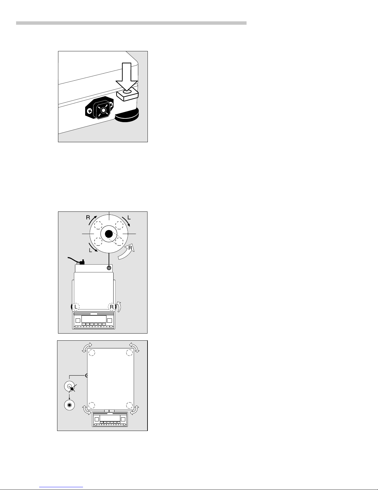
Fastening an Antitheft Locking Device:
Balances with a Weighing Capacity of 12 kg
To fasten an antitheft locking device, use the lug located
on the rear panel of the balance.
● Secure the balance at the place of installation, e.g.,
with a chain or a lock.
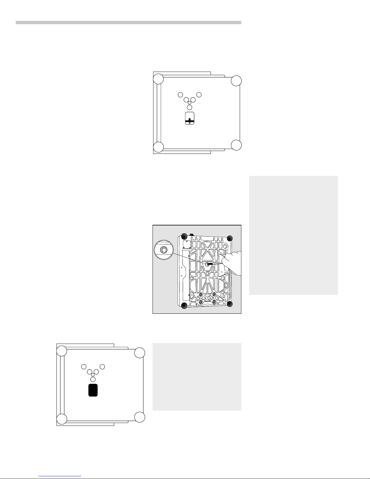
Leveling the Balance
Purpose:
– To compensate for unevenness at the place of installation
– To achieve perfectly horizontal positioning of the balance
for consistent reproducibility
Always level the balance again any time after it has been moved.
Leveling Balances with a Weighing Capacity ≤12 k g
Only the 2 front feet are used for leveling.
● Retract the 2 rear feet
● Turn the 2 front feet as shown in the diagram until the air bubble
is centered within the circle of the level indicator
> Several leveling steps are usually required.
● For weighing heavy samples:
Extend the 2 rear feet until they touch the surface on which the
balance rests
Leveling Balances with a Weighing Capacity ≥16 kg
● Adjust the four leveling feet until the air bubble is centered
within the circle of the level indicator
10
Configuring the Balance
Purpose
You can configure your Master
pro
balance to meet individual
requirements by entering user data
and setting parameters in the Setup
menu. You can also configure the
display to show balance-specific
information (such as the serial no.).
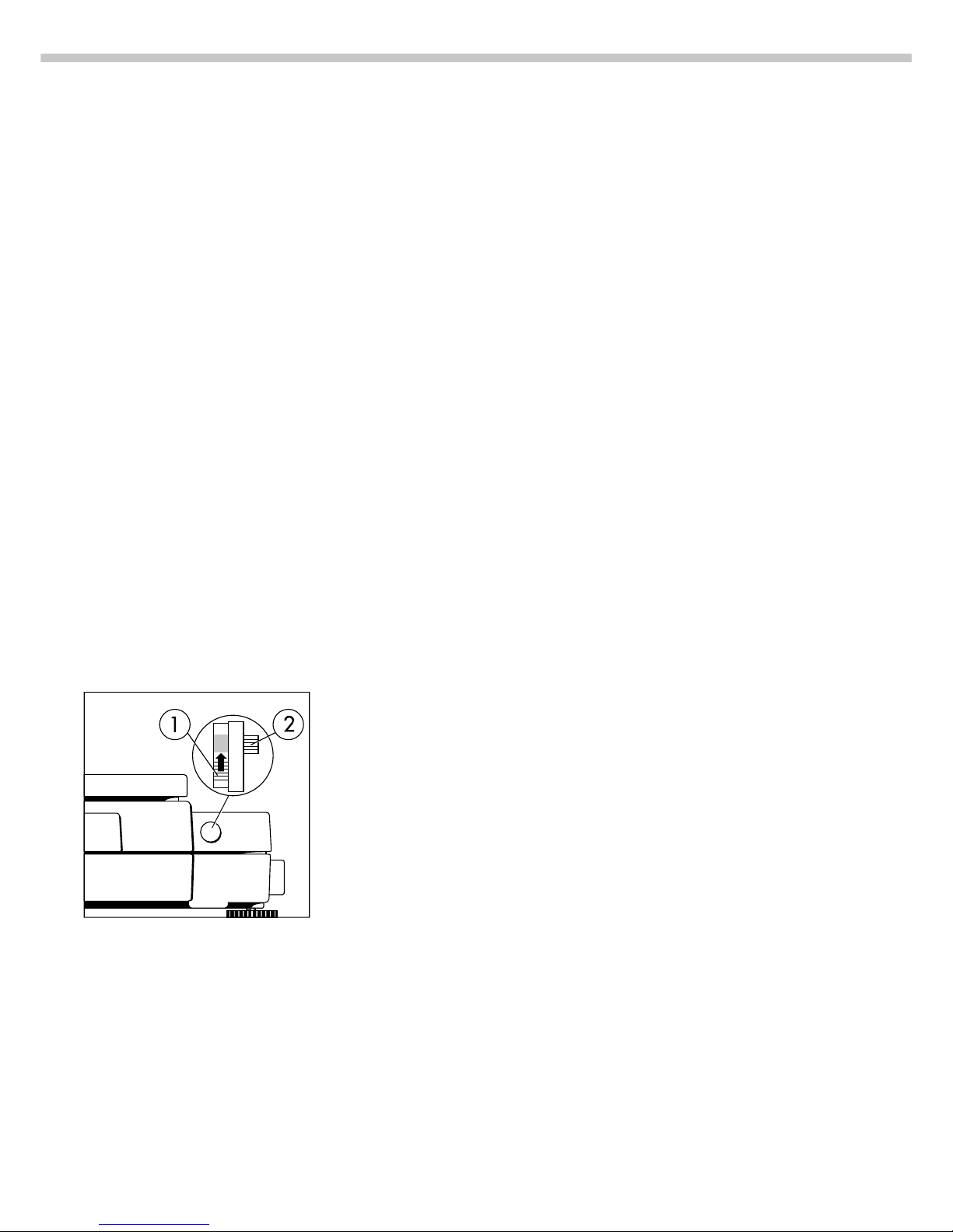
Setting the Function Switch for Using
the Balance in Legal Metrology
To use the balance in legal
metrology, the following functions
must be activated by setting the
switch as described below:
– Display: Verification scale interval e;
lower weighing range limit:
Min
– External calibration/adjustment:
Blocked
– MP8 interface emulation active
Preparation
● Remove the covering plate from the
back of the balance housing
● Move switch 1 in the direction of
the arrow
> Switch up:
external calibration blocked
Switch down:
external calibration accessible
> Note:
Do not move Switch 2
Setting the Language
Available Features
You can choose from 5 languages
for the information display:
1German
2 English (factory setting)
3 English with U.S. date/time
format
4 French
5 Italian
6 Spanish
Selecting the Language
● Enter the corresponding number
● Press M
’Info’ Display
Purpose
To have information about the
equipment displayed.
Features
You can have the following
information displayed:
– Program version number
for the display and control unit
– Program version
for the weighing cell
– Balance model
– Serial number of the weighing cell
Display Balance Information
● Select the Setup menu:
Press M
● Select information:
Press the info soft key q
> Readout in measured value line:
Version number of the display and
control unit (see also “Data Output
Functions,” pages 56–57, in the
chapter entitled “Operating the
Balance”)
k Select next item of information:
Press Y
> Readout in measured value line:
Next information
k Select previous information:
Press y
> Readout in measured value line:
Previous information
k Print information: Press p
> Printout (example)
Mod. LP6200S
Ser. no. 60406906
Ver. no. 01-30-13
Software version
(display and control unit)
Ver. no. 00-20-07
Software version
(weighing platform)
● Exit the Setup menu:
Press M
> Balance returns to previous status

11
Configuring the Balance
Entering User Data (Input)
Purpose
To display, input or change user
data. You can block access to these
data by assigning a password.
Features
You can display, input or change
the following user data:
– Workstation number* for the
balance: ID (balance ID; max.
20 characters)**
– Weighing series number, to
designate a series or lot:
L ID (lot ID; max. 20 characters)**
– Weight set number for calibration/
adjustment: W ID (weight ID;
max. 14 characters)**
– Exact weight value for calibra-
tion/adjustment of the balance
(see the section on “Calibration/
Adjustment,” starting on page 24
in the chapter entitled “Operating
the Balance; in particular refer
to page 27)
– Password for access to the Setup
menu: Input and Setup:
Menu (max. 8 characters)**
*** Only in conjunction with
ISO/GLP-compliant printouts
(see the section on “Setting
Parameters” in the chapter
entitled “Configuring the
Balance;” under menu code
number 8 10 x).
** A decimal point is displayed
together with its preceding digit
or character; it does, however,
count as a separate character.
This also applies when you
enter S ID and NUM as well
as to data entered via the
interface.
*** To delete user password:
Enter a decimal point using the
. key and confirm
Factory Settings
Password: No designation
If no password has been assigned,
anyone can access the “Setup:
Input” and “Setup: Menu” functions
without entering a password.
If you assign a password and then
forget what the word is, you can use
the General Password (see Appendix)
to access these menus.
Preparation
Display existing user data
● Select the Setup program:
Press M
> The soft keys Info, Menu and
Input are displayed in the text
line
● Select the user data input function:
Press the Input softkey v
> The password prompt is displayed
k If access is blocked by
a password: enter the password
using the alphanumeric input keys
● Display user data:
Press the enter passw.
soft key v
> The last 8 digits of a workstation/
balance number (ID no.), if
any ID is assigned, are displayed
in the measured value line
Enter/Change Password
● Select the Setup menu:
Press M
> The soft keys Info, Menu and
Input are displayed in the text
line
● Select the user data input function:
Press the Input soft key v
If you have already assigned
a password:
> The password prompt is displayed
k Enter the password
k Press the enter passw.
soft key v
● Write down the password here:
Password = .............................
If you no longer remember the
password assigned:
k Enter the General Password
(see Appendix)
k Press the enter passw.
soft key v
> The last 8 digits of a workstation/
balance number (ID no.), if any ID
is assigned, are displayed in the
measured value line
● Select password setting: Press y
> Password is displayed
in the text line
> If a password exists, it is now
displayed in the measured value
line
● New password: Enter the letters/
numbers for the new password
(8 characters max.)**
The password “none” means that
no password is stored.***
● Confirm input: Press X
● Exit the Setup menu:
Press M
> Restart the application
12
Practical Example
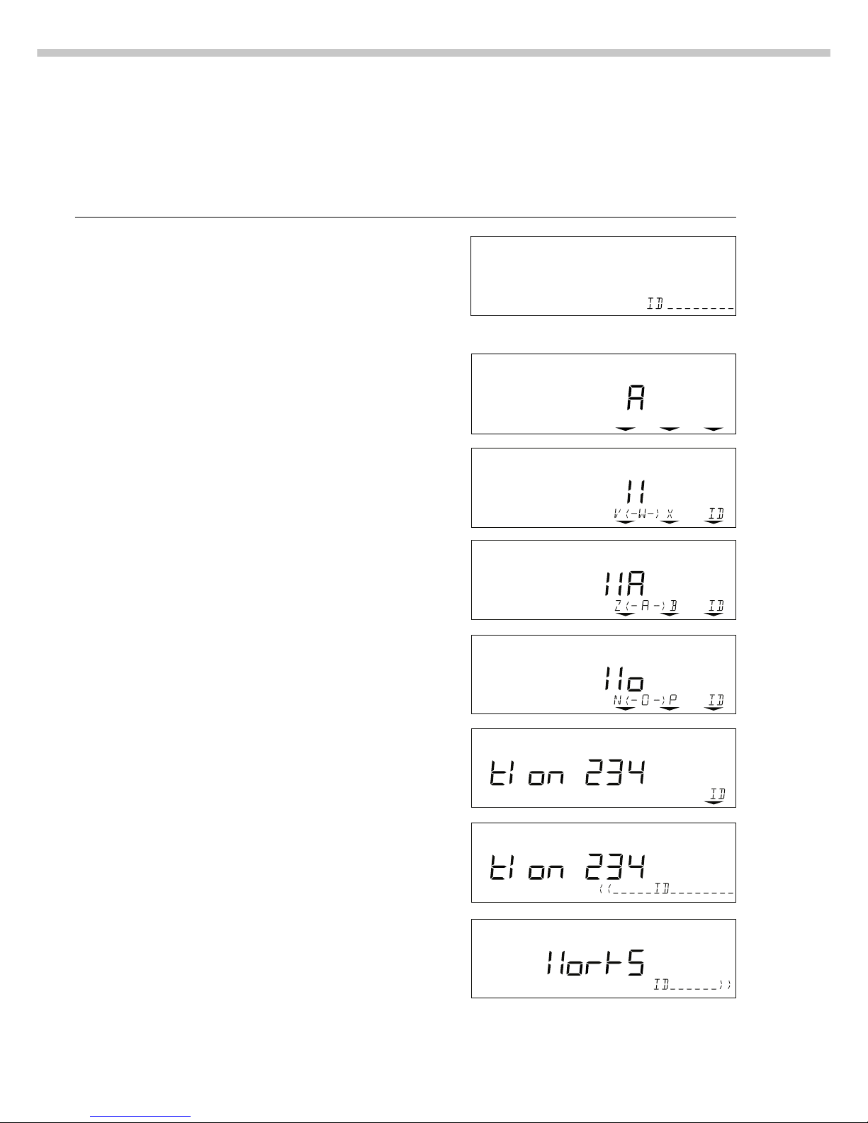
Enter “Workstation 234” as Balance ID; Display and Print Other User Data
Step Key (or instruction) Display/Output
1. Select Setup menu, then Input; see Preparation
Display balance workstation ID (in
this example: no ID number exists)
2. Enter the first letter of the balance a 13th through 20th digits of ID displayed
workstation ID
3. Set the letter “W” y repeatedly, until the W
is in the middle
4. Enter the next letter of the balance a
workstation ID
5. Select the letter “o” Y repeatedly
6. Repeat steps 4 and 5 with a x X
the appropriate letters (display
“longer” values: see “Data Output
Functions” on page 57)
7. Store balance workstation ID ID soft key (X)
8. Display the 5th through 12th digits x
of the balance workstation ID
IDz(- a -)b
13
Configuring the Balance
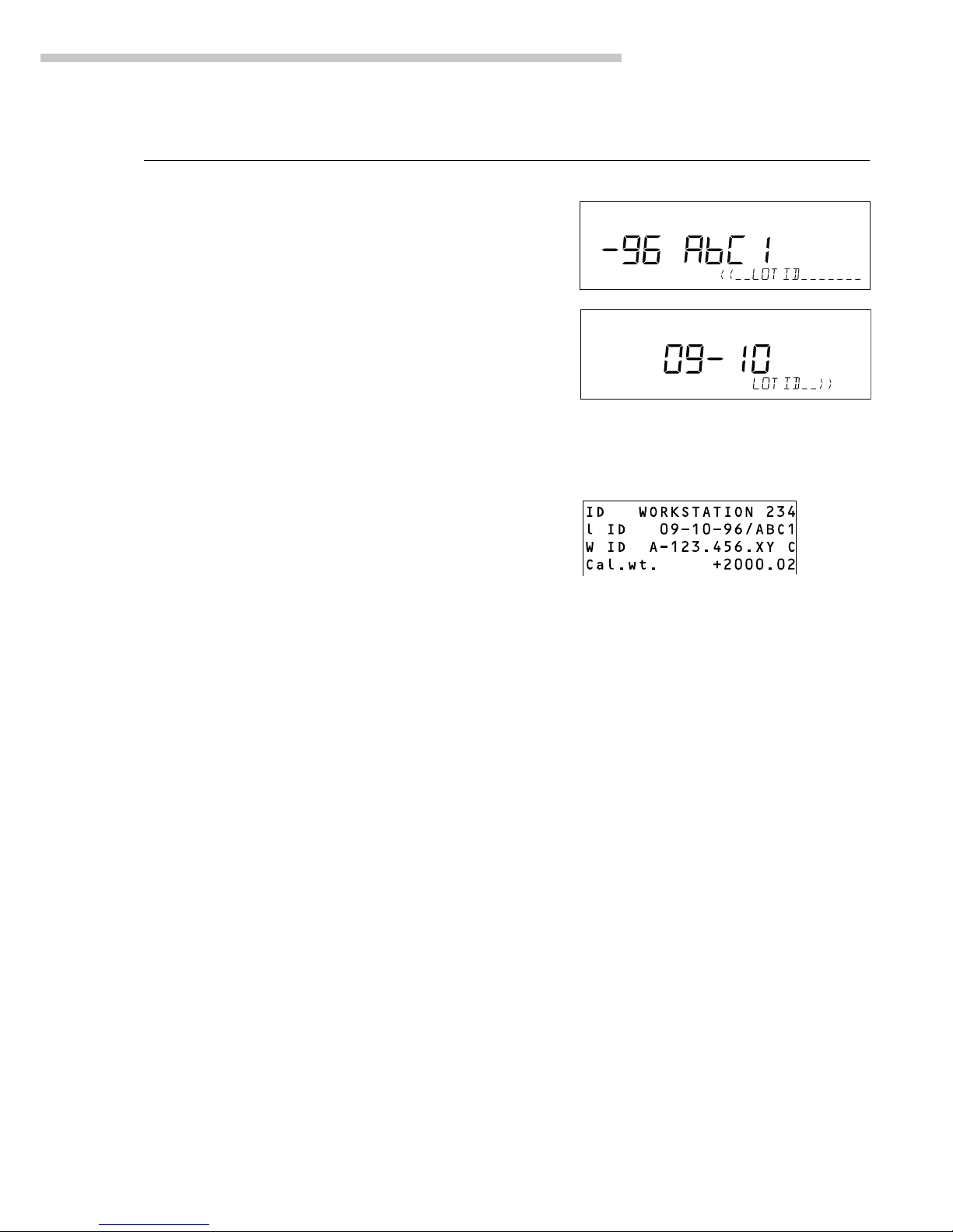
Step Key (or instruction) Display/Output
9. Display lot number Y 13th through 20th digits displayed
(In this example: 09-10-96/ABC1)
10. Display 5th through x
12th digits of lot no.
11. Display other user data xyYX
– Weight set no.
– Exact calibration weight
– Password
12. Print user data (example) p
13. Exit “Setup: Input” M

14
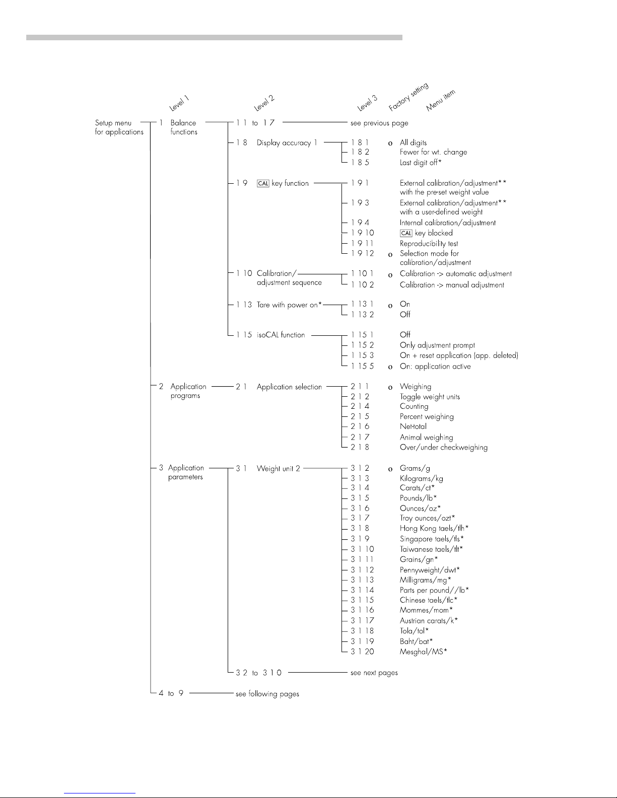
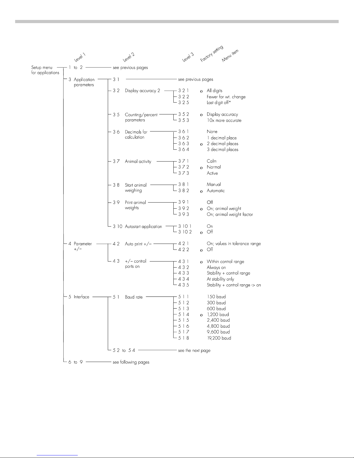
Setting Parameters (Menu)
Purpose
To configure the balance; i.e.,
adapt the balance to individual
requirements by choosing from
a list of parameter options in
a menu. You can block access
to this menu by assigning
a password.
Features
The parameter options are
divided into the following groups
(1st menu level):
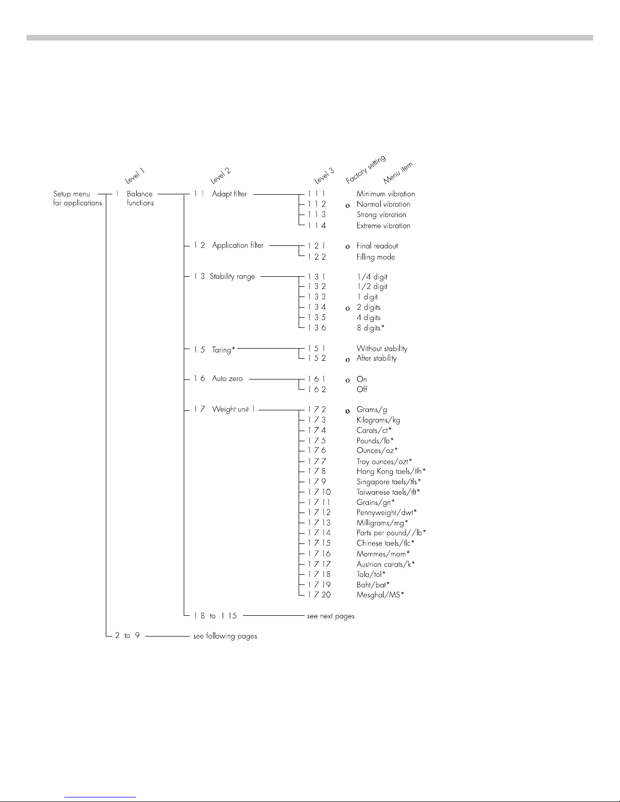
1 Balance functions
2 Application programs
3 Application parameters
4 +/– parameter
(for over/under checkweighing)
5 Interface parameters
6 Print for weighing (print weights)
7 Print for application program
(print app. data)
8 Additional functions
9 Reset menu
Factory Settings
The factory-set configurations
are marked with an “o” in the list
starting on page 16
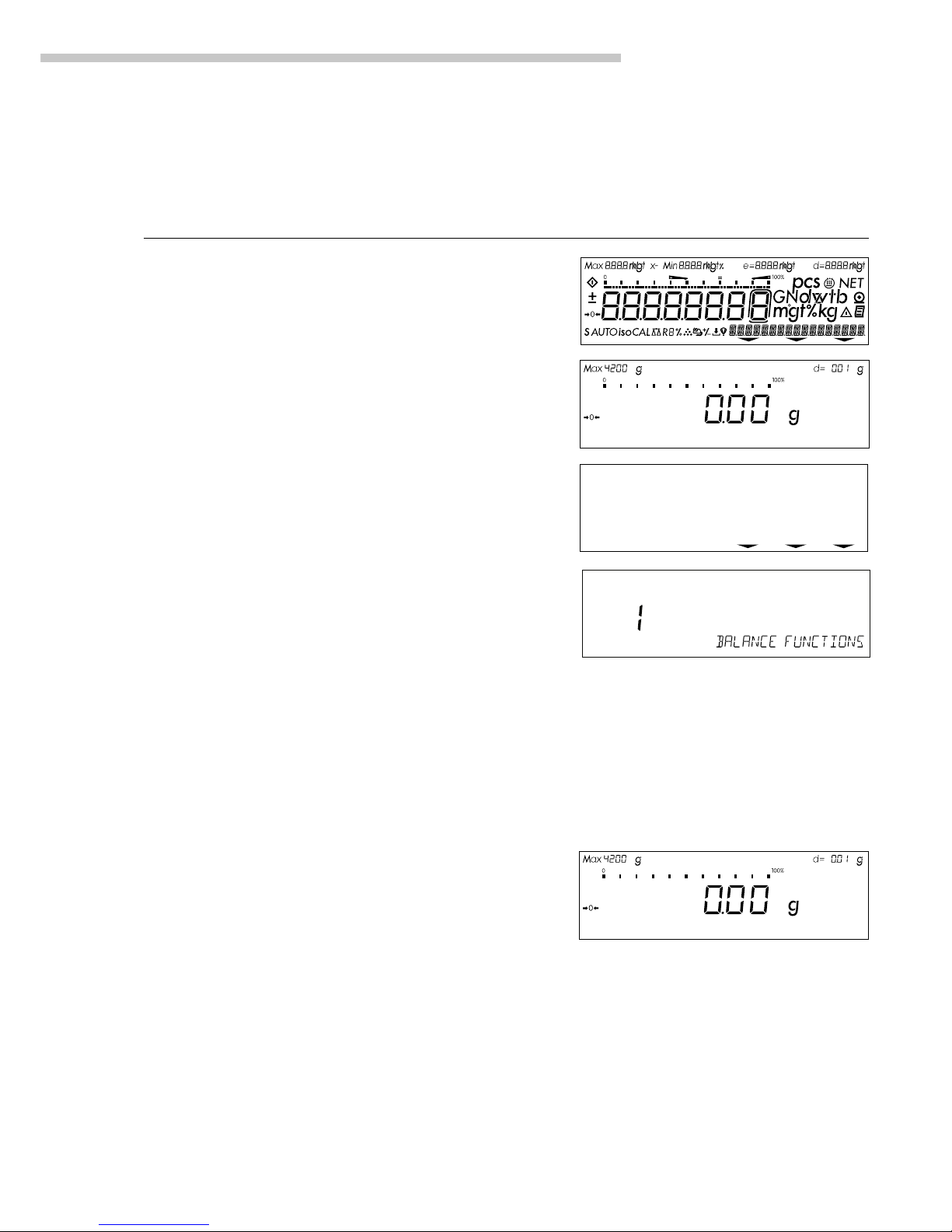
Preparation
● Select the Setup menu:
Press M
> The Info, Menu and Input soft
keys are displayed in the text line
● Select the parameter menu:
Menu soft key w
> Password prompt is displayed
● Enter password using the alpha-
numeric input keys
● Confirm password entered:
enter passw. soft key v
> Measured value line:
1 (1st menu level)
> Text line: Balance functions
k Select the next group: Press Y
k Select the next submenu
within a group (2nd menu level):
Press X
k Select previous group: Press y
k Return to next higher menu level:
Press x
Additional Functions
● Exit the menu: Press M
> Restart the application
● Print parameter settings:
– When the 3rd menu level
is selected: Press p
> Printout (example)
4 2 Auto print +/ 2 Off
– When the 2nd menu level
is selected: Press p
> Printout (example)
4 Parameter +/-
------------------4 2 Auto print +/ 2 Off
4 3 +/- ctrl ports
1 Within ctrl r
– When the 1st menu level
is displayed: Press p
> Prints all of the menu parameters
that are currently set
15
Configuring the Balance
Practical Example
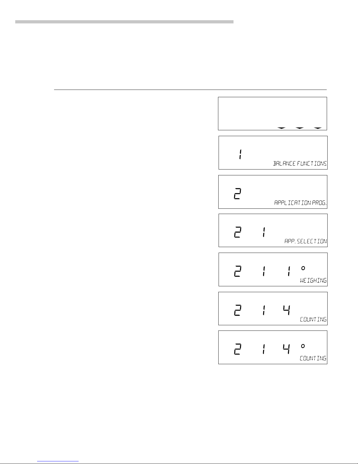
Select the Counting Application Program
Step Key (or instruction) Display/Output
1. Select Setup menu M
2. Select Balance Functions Menu soft key w
group code (Menu)
3. Select the Application Y
Prog. group
4. Confirm Application Program X
(2nd menu level)
5. Confirm App. Selection X
(3rd menu level shows current
setting; in this case: weighing)
6. Select the Counting program Y Y
7. Confirm selection X
of Counting program
8. Set other parameters, if desired x y Y X
9. Save settings and exit menu M
info--menu--input
16
Setup Parameters (Overview)
o Factory setting
√ User setting
* = setting not applicable in balances verified for use in legal metrology
17
Configuring the Balance
* = setting not applicable in balances verified for use in legal metrology
** = for balances of accuracy class K, only calibration (not adjustment) can be performed with a user-defined weight
18
* = setting not applicable in balances verified for use in legal metrology

19
Configuring the Balance
Setup menu 1 to 4 see previous pages
for applications
5 Interface 5 1 see previous page
5 2 Parity 5 2 2 Space
5 2 3 ο Odd
5 2 4 Even
5 3 No. of stop bits 5 3 1 ο 1 stop bit
5 3 2 2 stop bits
5 4 Handshake 5 4 1 Software handshake
mode 5 4 3 ο Hardware handshake,
1 character after CTS
5 5 Communication 5 5 1 ο SBI
mode 5 5 2 xBPI
5 5 4 YDP01IS
5 5 5 YDP02
5 5 6 YDP03
5 5 7 YDP01IS Label printer
5 5 10 YDP02IS
5 5 11 YDP02IS Label printer
5 5 14 YDP04IS
5 5 15 YDP04IS Label printer
5 6 Network address 5 6 1 ο Address 0
5 6 x Addresses 1 to 30
5 6 32 Address 31
6 Print for 6 1 Print manual/ 6 1 1 Manual without stability parameter
weighing automatic 6 1 2 ο Manual with stability parameter
6 1 4 Auto print without stability parameter
6 1 5 Auto print at stability
6 1 6 Auto print after weight change**
6 2 Stop auto print 6 2 1 Use p key
6 2 2 ο Not possible
6 3 Time-dependent 6 3 1 1 display update
auto print 6 3 2 2 display updates
6 3 4 10 display updates*
6 3 7 100 display updates*
6 4 Print -> 6 4 1 ο Off
autotare 6 4 2 On
7 Print for 7 1 Print application 7 1 1 ο Off
application parameters 7 1 2 All parameters
7 1 3 Only main parameters
7 2 Line format 7 2 1 For raw data
7 2 2 ο For other applications/GLP
7 3 Print net total 7 3 1 ο Auto print net
7 3 2 Auto print tare
8 Extra functions 8 1 Menu 8 1 1 ο Parameter settings alterable
8 1 2 Parameter settings readable
8 2 to 8 10 see next page
9 Balance menu see next page
Level 1
Level 2
Level 3
Factory setting
Menu item
* = setting not applicable in balances verified for use in legal metrology
** = Auto print if change in weight >10 d and has stable readout; function enabled when load <5 d

20
* = not in balance models with a weighing capacity ≥16 kg.
21
Operating the Balance
Operating the Balance
Basic Weighing Function
Purpose
The basic weighing function
is always accessible and can be
used alone or in combination with
an application program (Toggle
between Weight Units, Counting,
Weighing in Percent, etc.).
Features
– Taring the balance
– Assigning IDs to weights
– Printing weights
– Printing ID codes for weights
Factory Settings
Tare: After stability (1 5 2)
Print manual/automatic:
Manual after stability (6 1 2)
Line format for printout:
For other applications/GLP (7 2 2)
Alphanumeric input of a weight ID:
Keys unblocked (8 3 1)
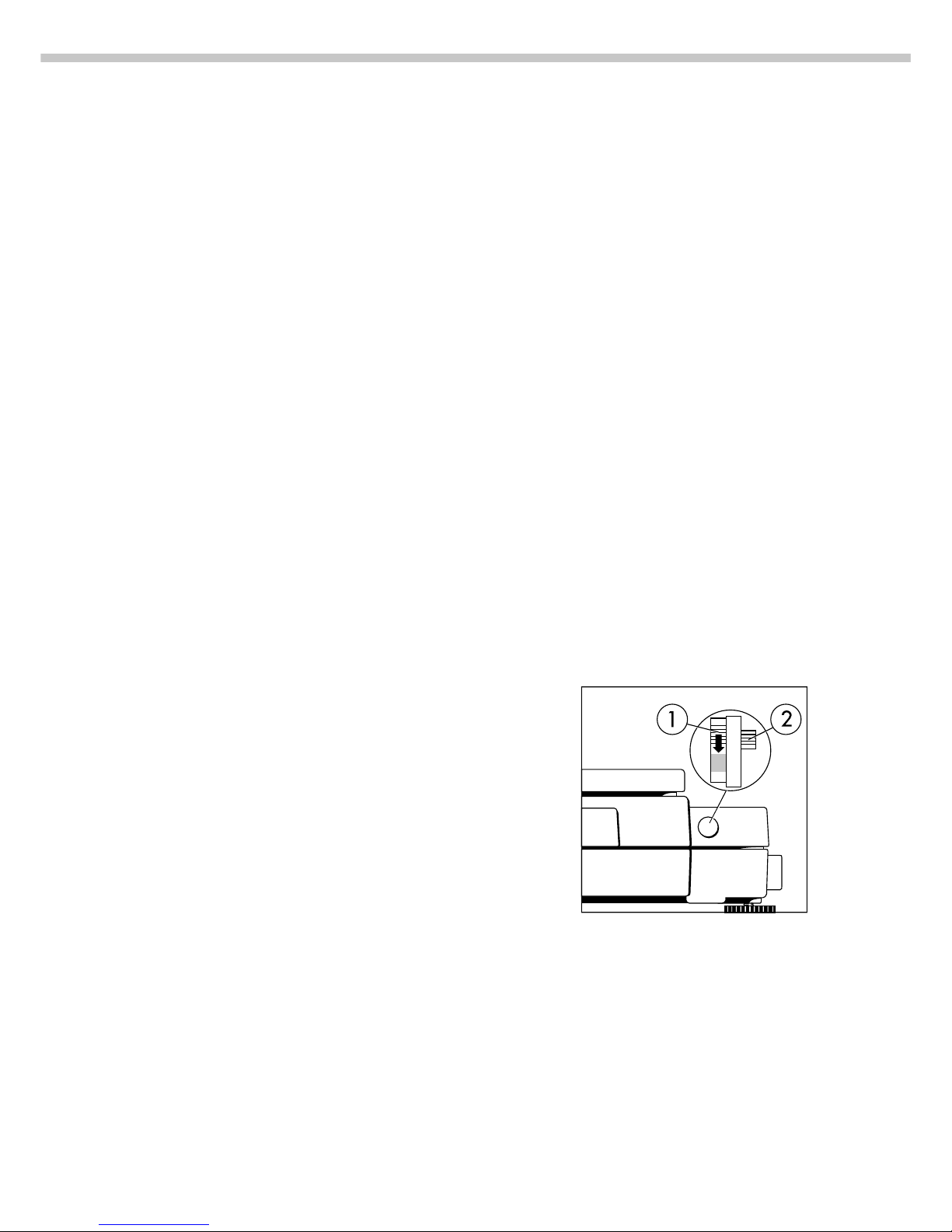
Below-Balance Weighing
A port for a below-balance
weighing hanger is located on the
bottom of the balance.
Balances with a weighing capacity
>12 kg:
● Open cover plate (1) on the
bottom of the balance
1
● Attach the sample (e.g., using a
suspension wire) to the hook (2).
2
k If necessary, install a shield for
protection against drafts
Balances with a weighing capacity
≥ 16 kg:
● Use a screwdriver to open
the cover plate on the bottom
of the balance
● Attach the hook ordered directly
from Sartorius
Important Note Concerning
Verified Balances Approved
for Use as Legal Measuring
Instruments in the EU*:
The below-balance weighing port
may not be opened or used when
an approved balance is being
operated as a legal measuring
instrument.
Preparation
● Turn on the balance: Press e
> All display segments light up
briefly
k To change configurations:
see the chapter entitled
“Configuring the Balance”
k To load factory-set configurations:
see “Configuring the Balance,”
parameter 9 1
k To tare the balance: Press t
> The U symbol is displayed
when the balance is zeroed
or tared (only on balances verified
for use in legal metrology)
Using Verified Balances
Approved for Use as Legal
Measuring Instruments in the EU*:
The type-approval certificate for
verification applies only to nonautomatic weighing instruments;
for automatic operation with
or without auxiliary measuring
devices, you must comply
with the regulations of your
country applicable to the place
of installation of your balance.
$ The temperature range
indicated on the verification ID
label must not be exceeded
during operation
* including the Signatories
of the Agreement on the European
Economic Area
22
ID for weight value (if desired):
● Select the parameters
“Line format” and “For other
app./GLP” from the
Setup menu: Press M
● Select mode:
Press the menu soft key
● Set parameter 7 2 2: See the
chapter entitled “Configuring the
Balance”
● Exit the Setup menu:
Press M
Additional Functions
In addition to the functions:
– alphanumeric input,
– taring
(not during alphanumeric input),
– printing,
you can also access
the following functions from the
weighing application:
– calibration
(not during alphanumeric input),
– setup,
– turning off the balance.
Calibration
● Press q
> See the section on “Calibration/
Adjustment” for further instructions.
Setup Menu
● Press M
> See the chapter entitled
“Configuring the Balance” for
further instructions.
Turning Off the Balance
● Press e
> The balance shuts off
> The display goes blank
Important Note Concerning
Verified Balances of Accuracy
Class k:
To avoid measuring errors, the
respective air density must be
allowed for. The following
formula is used to calculate the
mass of the sample:
1 – ρ
L
/8000 kg m
–3
m= n
w
1 – ρL/ρ
m = mass of the sample
nw= weight readout
ρ
L
= air density during weighing
ρ = density of the sample
Practical Examples
Example W1: Simple Weighing
Step Key (or instruction) Display/Output
1. If necessary, tare the balance t
(U symbol: balance is tared,
– verified balances only)
2. Enter sample ID see Example W2
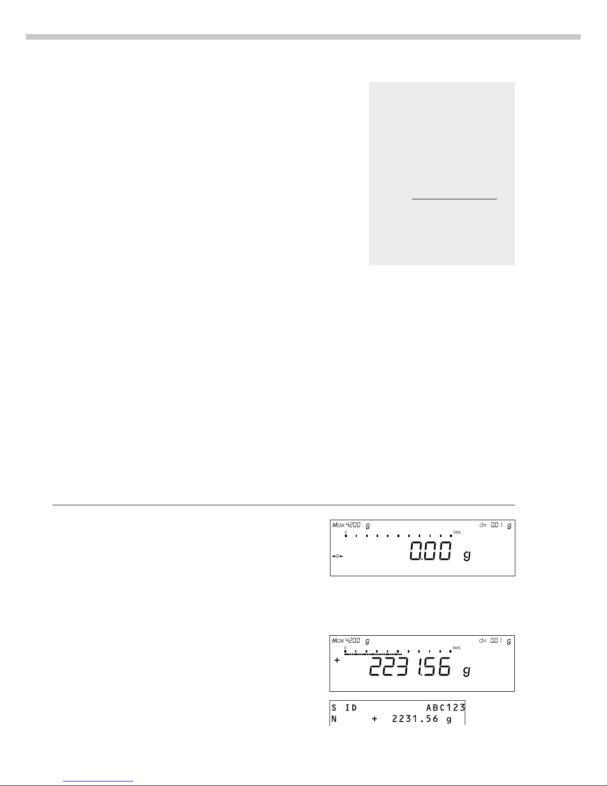
3. Determine sample weight Place sample on balance
(Example)
4. Print weight p
23
Operating the Balance
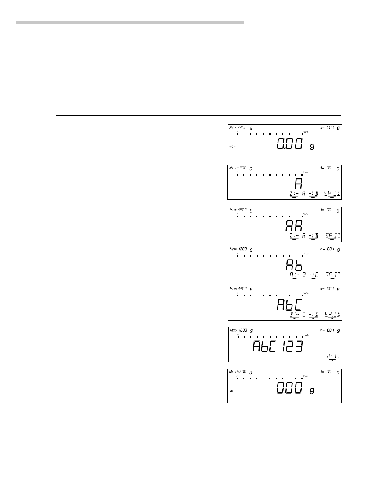
Example W2
Enter “ABC123” as a sample ID
Note:
– The sample ID generally applies to one weighing operation only
– The ID is deleted after data output
Step Key (or instruction) Display/Output
Initial status (balance unloaded)
(ID can also be entered while balance
is loaded)
1. Enter the letter “A” a
2. Select and enter the letter “B” a
Softkey B (Key Y)
3. Select and enter the letter “C” a Softkey . .
(Key Y Y)
4. Enter the numbers “1,” “2” and “3” 1 2 3
5. Store the ID Press the SP.ID soft key v
(max. 20 characters)
– The next printout will include this ID
24
For service technicians only:
External Calibration in Verified
Balances of Accuracy Class K
– External calibration is blocked
when the balance is used in
legal metrology
> External calibration can only
be released after removing the
verification control seal, in which
case the validity of the erification
becomes void and the balance
must be re-verified
– External calibration can now
be performed
Factory Settings
Calibration/adjustment mode:
Selection mode (1 9 12)
Calibration/adjustment sequence:
Adjustment automatically follows
calibration in a single operation
(1 10 1)
Automatic initiation of calibration/
adjustment (isoCAL function):
isoCAL on (1 15 5)
ISO/GLP printout: off (8 10 1)
Adjustment can be performed
– automatically following calibration
(1 10 1); or
– if desired, the adjustment
operation can be started manually after calibration (1 10 2)
You can also configure whether
the calibration mode
– will be activated according
to the specific setting (by setting
1 9 1, 1 9 3 or 1 9 4), or
– can be selected by the user after
pressing the q key (1 9 12).
You can have the balance
automatically display an adjustment
prompt after a certain time interval
has elapsed since the last
calibration/adjustment or when
the ambient temperature changes by
a defined amount.
You can also configure the balance
to perform calibration and
adjustment automatically (isoCAL)
when the pre-set time and/or
temperature limit is reached
(1 15 3 and 1 15 5).
You can have the calibration/
adjustment results documented in
a ISO/GLP-compliant printout.
Releasing Access to External
Calibration in Verified Balances
of Accuracy Class k
§ Remove the covering plate from
the back of the balance housing
§ Move Switch 1 in the direction
of the arrow
> Switch down:
external calibration accessible
Switch up:
external calibration blocked
> Note:
Do not move Switch 2
Calibration/Adjustment
Purpose
Calibration is the determination
of the difference between the
weight readout and the true weight
(mass) of a sample. Calibration
does not entail making any changes
within the balance.
Adjustment is the correction of this
difference between the measured
value displayed and the true
weight (mass) of the sample, or the
reduction the difference to an
allowable level within the maximum
permissible error limits.
Available Features
Your balance can be calibrated
externally (menu item 1 9 1 or1 9 3)
or internally (1 9 4).
External calibration can
be performed
– with the pre-set weight value
(1 9 1), or
– with a user-defined weight value
(1 9 3)
* including the Signatories of the
Agreement on the European
Economic Area
25
Operating the Balance
Preparation
Configure Parameters for Calibration and Adjustment
Step Key (or instruction) Display/Output
1. Turn on the balance e
2. Select the Setup menu M
3. Select the Balance Functions menu menu soft key w
4. Set parameters for:
– Calibration key function 1 9
– Calibration/adjustment
sequence 1 10
– isoCAL self-calibrating and
adjustment function 1 15
See the chapter entitled “Setup” x y Y X
5. Exit the Setup menu M
info--menu--input
26
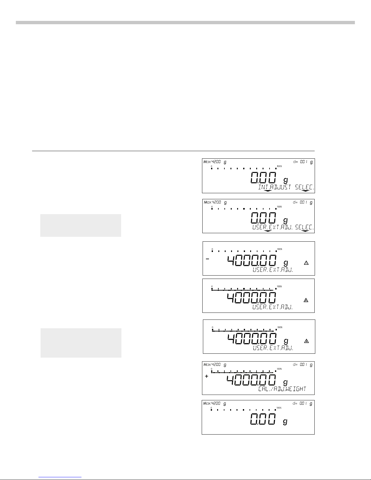
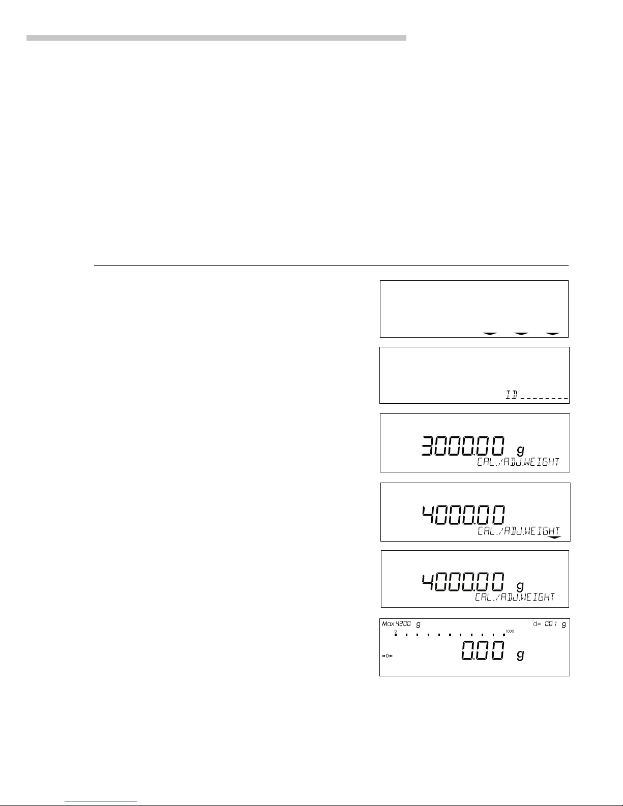
Configure External Calibration and Automatic Adjustment of the Balance in Selection Mode
Step Key (or instruction) Display/Output
1. Select the calibration function q
2. Select external calibration/ Press the selec.
adjustment mode soft key three times v
(for balances of accuracy
class K, only “external
adjustment” is possible)
3. Confirm external calibration/ Press the
adjustment mode user. ext.adj. soft key q
4. Place the calibration weight Place weight on balance
on the balance (e.g., 4000.00 g)
Minus sign –: Weight too low
Plus sign +: Weight too high
No plus/minus sign: Weight o.k.
This is displayed after calibration:
(on verified balances, the
display shows the difference
between the weight readout
and the actual weight value)
This is displayed after adjustment:
5. Unload the balance Remove weight(s)
Selecting the Calibration/
Adjustment Parameter
The setting 1 9 12 must be selected
in the Setup menu.
You can configure the balance
so that after selecting a calibration
procedure by pressing the q key,
you can choose among the following
calibration/adjustment modes:
– External calibration/adjustment
with the pre-set weight value
(Def. Ext. Adj.)
– External calibration with
a user-defined weight value
(user. ext.adj.)
– Internal calibration (int. adjust)
– Reproducibility test (reprotest)
When making your selection,
the available modes
are displayed in cycles; i.e.,
after reprotest, def. ext.adj.
is displayed again
27
Operating the Balance
External Calibration/Adjustment*
with a User-Defined Weight
First set either 1 9 3 or selection
mode (1 9 12) in the menu.
You can define a weight for
calibration/adjustment.
External calibration/adjustment must
be performed with weights that are
traceable to a national standard and
that have error limits which are at
least 1/3 of the required tolerance
of the display accuracy.
The balance has a factory-set weight
value (see “Specifications”).
Define the Calibration Weight
Step Key (or instruction) Display/Output
1. Select the Setup menu M
2. Access the Input Mode Input soft key v
3. Select input for calibration Y Y Y
weight (currently 3000.00 g)
4. Enter calibration weight 4 0 0 0 . 0
(e.g., 4000.00 g) 0
5. Save weight … weight soft key v
6. Exit the Setup menu M
* = for verified balances of accuracy class K, only external calibration is possible
info--menu--input
To reset a user-defined calibration/
adjustment weight to the original
factory setting, enter the factory-set
weight value manually (see
“Specifications”) or set menu code
1 9 1 in the Setup menu.

28
Internal Calibration/Adjustment
The menu code setting 1 9 4 must be
selected in the Setup menu.
Inside the balance housing is a builtin, motorized calibration weight.
The internal calibration/adjustment
sequence is as follows:
● Select the calibration function:
Press q
> The internal calibration weight
is applied automatically
> The balance is calibrated
> If the setting for “Calibration
automatically followed by
adjustment” (1 10 1) is selected
in the Setup menu, the balance is
now automatically adjusted
> The internal calibration weight
is removed
Calibration and Adjustment Sequence
In the Setup menu, you can configure
the balance so that:
– calibration is always followed
automatically by adjustment
(cal. -> auto adjust, 1 10 1), or
– you have the choice of ending
the sequence or starting adjustment after calibration
(cal. -> man. adjust, 1 10 2).
If no deviation is determined during
calibration, or the deviation is within
the tolerance limits dictated by the
degree of accuracy you require, it is
not necessary to adjust the balance.
In this case, you can end the
calibration/adjustment sequence
after calibration. There are 2 soft
keys active at this point:
– ext. adjust or int. adjust
to start adjustment
– end to end the sequence

29
Operating the Balance
isoCAL:
Automatic Calibration and Adjustment
Either 1 15 3 or 1 15 5 must be
selected in the Setup menu.
The “isoCAL” display automatically
begins flashing if the ambient
temperature has changed in relation
to the temperature at the time
of the last calibration/adjustment,
or after a defined time interval
has elapsed. The balance is telling
you that it wants to self-calibrate
and adjust.
This adjustment prompt is activated
when:
– The change in temperature
or the elapsed time interval is
greater than that shown
in the table below
– The balance status does not
correspond to Setup configurations
– No number or letter input is active
– The load on the pan has not been
changed within the last 2 minutes
– The balance has not been
operated within the last 2 minutes
– The weight on the pan must be
no more than 2% at the most of
the maximum capacity of the
balance
When these requirements are met,
the following symbols are displayed:
– C in the measured value line
–
isoCAL
in the symbol display
– G in the weight unit display
If the balance is not operated and
the load is not changed, internal
calibration and adjustment starts after
15 seconds have elapsed.
In the Setup menu, you can
configure the balance so that after
calibration and adjustment
– the application program
must be restarted
(On + reset app. 1 15 3), or
– the application program
resumes where it left off
(isoCAL on, 1 15 5)
Fully automatic adjustment is initiated under the following conditions:
Model When the temperature After a time
changes by interval of
LP 3200D, LP 1200S 1.5 Kelvin 4 h
LP8200S, LP8200P, 2 Kelvin 6 h
LP 620S, LP 620P, LP 6200S,
LP 4200S, LP 5200P, LP 220S
LP 2200S, LP 2200P, 4 Kelvin 12 h
LP 34001P, LP 34001S, LP 64001S
LP 820, LP 420, LP 16001S, 4 Kelvin 24 h
LP 12000S, LP 12000P,
LP 6200, LP 4200, LP 2200,
LP 34000
These values are also set in the corresponding verified or verifiable balances
(LP models with the -0CE designation).
In the Setup menu, you can also
configure the balance so that it
displays an adjustment prompt,
but does not perform the calibration/
functions automatically
(Only adj. prompt, 1 15 2)
Function in Verified Balances:
Automatic calibration is also
performed outside of the limited
temperature range if you set menu
code 1 15 1, “isoCAL function: off”
or code 1 15 2, “only at adjustment
prompt” in the Setup menu.
To generally deactivate automatic
calibration in balances with
a weighing capacity ≤12 kg:
– After the balance has been
modified by the Sartorius
Service Center
> Afterwards, the balance
can only be used for legal
metrology within the
temperature range allowed
by law
Limited temperature range:
– For balances of accuracy
class k: +15°C to +25°C
(59°F to 77°F)
– For balances of accuracy
class K: +10°C to +30°C
(50°F to 86°F)
Extended temperature range:
–0°C to +40°C
(32°F to 104°F)
Deactivating the “isoCAL”
30
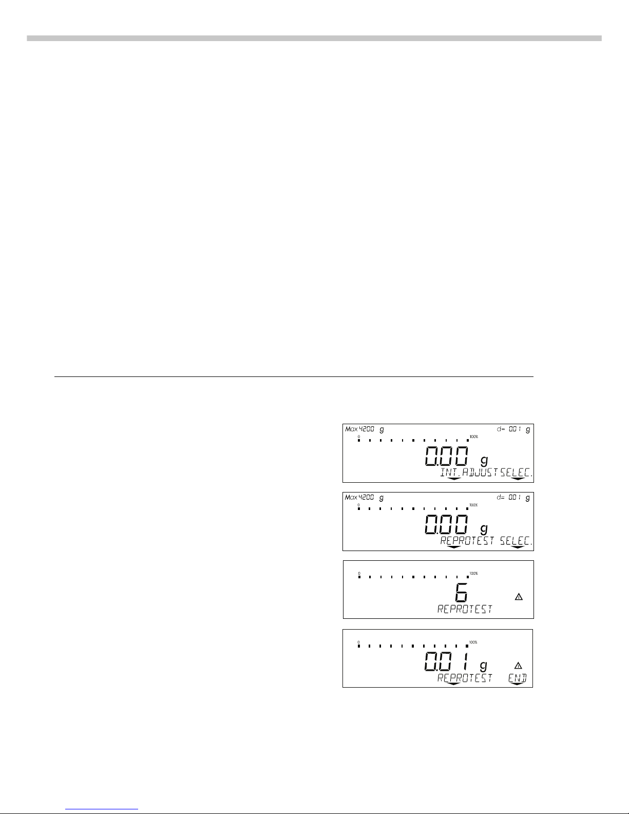
Check the Reproducibility of the Balance
Step Key (or instruction) Display/Output
1. If parameter 1 9 11 is set
(reproTEST), proceed with step 4.
2. Access the Selection Mode for q
calibration/adjustment
3. Select reproTEST selec. soft key v
4. Start reproTEST q
Number of measurements
is displayed
6 measurements will now
be performed
The standard deviation is displayed
5. End reproTEST End soft key v
or restart reproTEST reprotest soft key
Determination of the
Repeatability (reproTEST)
Definition
Repeatability (reproducibility) is the
ability of the balance to display
identical readouts when it is loaded
several times with the same weight
under constant ambient conditions.
The standard deviation for a given
number of measurements is used to
quantify the repeatability.
Purpose
The “reproTEST” function automatically calculates the repeatability of
results (based on 6 individual
measurements). In this way, the
balance determines one of the most
important quantities in relation to
the place of installation. The results
are displayed with the balance’s
accuracy.
Preparation
● Turn on the balance:
Press e
> All display segments light up
briefly
● Select reproTEST in the Setup
menu: Press M
● Select Menu:
Press w (menu softkey)
● Select either 1 9 11 (reproTEST)
or 1 9 12 (selection mode):
See “Configuring the Balance.”
● Exit the Setup menu:
Press M
 Loading...