

Sartorius LC 621S-00MS, AC 211S-00MS, LC 621P-00MS, LC 6201S-00MS, LC 4201S-00MS User Manual
...Page 1
Sartorius Master Series
Electronic Weighing Instruments
Accuracy Class k or K
Analytical and Precision Balances
Installation and Operating Instructions
for Standard Models
and EC-Approved Models Acceptable
for Legal Metrological Verification
98648-004-03
Page 2

Contents
Page
General Views of the Balances 1– 1
Warranty 1– 6
Storage and ShippingCondtions 1– 6
Installation Instructions 1– 7
Getting Started 1– 9
Connecting the Balance
to AC Power 1–10
Voltage Selection 1–11
Connecting Electronic Devices
(Peripherals) 1–11
Safety Precautions 1–11
Information on Radio Frequency
Interference 1–12
Adjusting the Display Unit 1–12
Information on Weighing Electrostatically Charged Samples 1–12
Leveling the Balance Using
the Level Indicator 1–13
Operating the Balance 1–14
Warmup Time 1–14
Turning the Display On and Off 1–14
Self-Test 1–14
Taring 1–16
Weighing 1–16
Weighing Range Structure 1–17
Weighing in the IQ-Mode
(Load-Dependent Readability) 1–18
Calibration 1–19
Sensitivity Test 1–23
Data Interface 1–25
Below-Balance Weighing 1–27
Fastening an
Antitheft Locking Device 1–27
Troubleshooting Guide 1–28
Care and Maintenance 1–30
Manufacturer’s Declaration 1–32
Page
Balance Operating Menu 2– 1
Changing a Menu Code Setting 2– 2
Undoing All Menu Code
Changes: Reset Function 2– 4
Balance Operating Parameters 2– 5
Adapting the Balance
to Ambient Conditions 2– 5
Standard Weighing Mode –
Manual Filling Mode 2– 5
Stability Range 2– 5
Stability Symbol Delay 2– 6
Tare Parameter 2– 6
Auto Zero Function 2– 6
Weighing in Three Ranges
on Standard Balances 2– 7
Selecting the Number
of Ranges 2– 7
Weight Units 2– 7
Weighing in Two Ranges
on Verified Balances 2– 9
Selecting the Number
of Ranges 2– 9
Weight Units 2– 9
Display Modes on
Standard Balances 2–10
Final Readout Mode 2–10
Last Numeral Blanked When
the Load Changes 2–10
Round-Off Function 2–10
IQ-Mode 2–10
PolyRange Function 2–11
Display Modes on
Verified Balances 2–12
Calibration Functions on
Standard Balances 2–13
0–1
Page 3

Page
Page
Calibration Functions on
Verified Balances 2–14
Utilities for Printouts
or Data Transfer 2–15
Data Output Parameter 2–15
Automatic Data Output 2–15
Data Output at Defined Intervals 2–16
Automatic Taring after
Data Output 2–16
Data ID Codes 2–17
Additional Functions 2–18
Menu Access Function on
Standard Balances 2–18
Function of the Menu Access
Switch on Verified Balances 2–18
Beep Tone (Acoustic Signal) 2–18
Blocking the Keys 2–18
Universal Switch for
Remote Control 2–19
Analog Display:
Bar Graph/Marker 2–19
Power-On Mode 2–19
Automatic Shutoff (Battery Saver) 2–20
Display Backlighting 2–20
“isoCAL” Self-Calibrating
Function on AC/LC…-00MS/
-0CEMS Models 3– 1
Range of Performance Features 3– 1
“isoCAL”Self-Calibrating Function 3– 2
Flashing W Symbol 3– 2
Activating Internal
Calibration Manually 3– 3
Automated Processes 3– 4
Printout or Record
of Calibration Processes 3– 4
Calibrating Balances when Using
YDK 01,
YWP 01, YWP 01U
or YWP 02 Accessories 3– 4
Calibration with the MC1-MP8
Interface (Binary Converter) 3– 4
Application Programs for Balances
of the Product Line 4– 1
Functions Common to All Programs 4– 2
Tare Memory 4– 4
Display/Print Tare –
Net – Gross Weights 4– 4
Net Total 4– 5
0–2
Weighing in Percent 4– 6
Determination of the Residual
Weight in Percent 4– 6
Sieve Analysis 4– 7
Over/Under Checkweighing 4– 9
Checking Net Weights 4–10
Checking Variations in Weight 4–11
Counting 4–13
Page 4

Page
Page
Interface Description 5– 1
General Specifications 5– 1
Data Output Formats 5– 2
Data Input Formats 5– 6
Table of ASCII Characters 5– 9
Synchronization and
Data Output Parameters 5–10
Settings for the
Interface Parameters 5–13
Control Lines 5–14
Pin Assignment Chart 5–15
Cabling Diagram 5–16
Product Data Sheets 6– 1
Specifications 6– 2
EC Pattern Approval Certificates 6–20
Dimensions (Scale Drawings) 6–24
Accessories (Options) 6–28
Declarations of Conformity 7– 1
The CE Mark of Conformity
on Sartorius Equipment 7– 1
“EC Verification” – A Service
Offered by Sartorius for Balances
Acceptable for Verification 7– 4
“New Installation” – A Service
Offered by Sartorius 7– 4
Subsequent Verifications within
the European Union 7– 4
Sartorius European Service
Center Addresses 7– 5
Declaration of Conformity
to Directive No. 90/384/EEC 7– 6
Certification for the Sartorius
Quality System for the Weighing
Technology Division (in German) 7– 7
Declaration of Conformity
to Directive 89/336/EEC 7– 8
Supplement:
Brief Instructions
0–3
Page 5
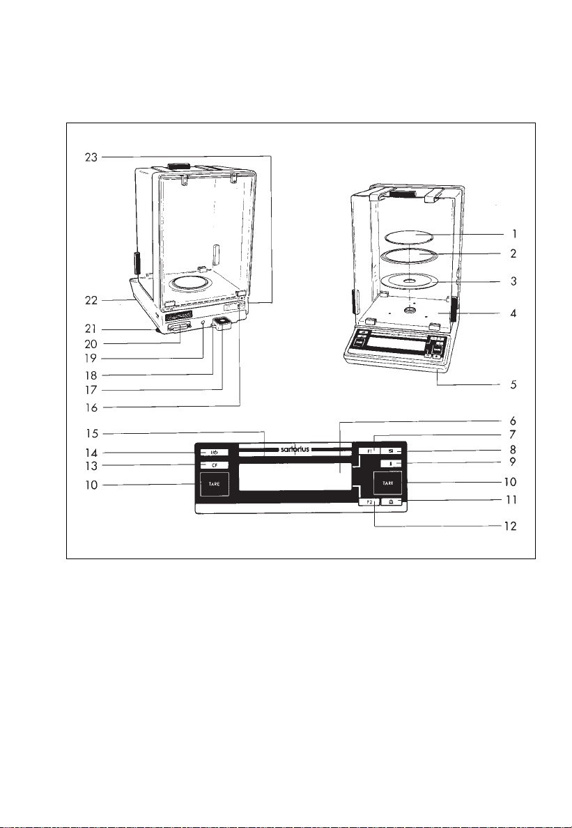
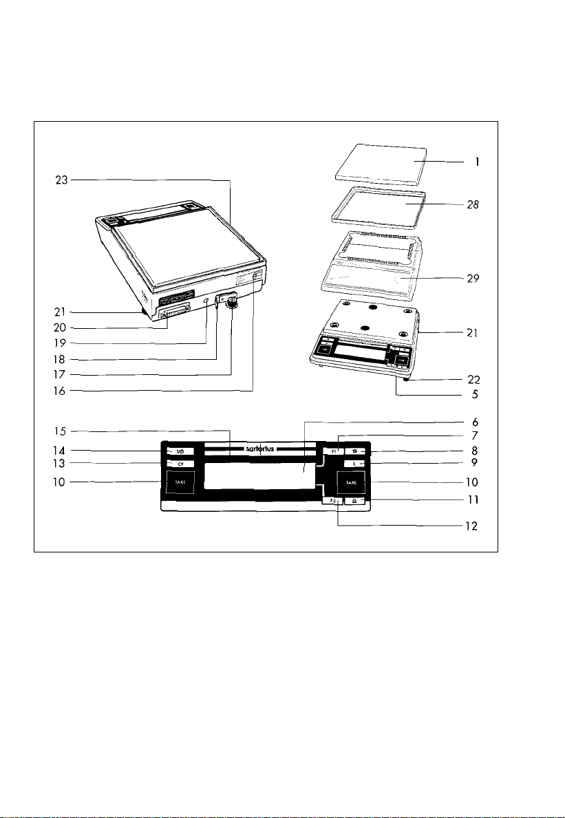
ACSeries Balances with an Analytical Draft Shield Chamber
1 Weighing pan
2 Protective ring
3 Shield plate
4 Draft shield base plate
5 Menu access switch
6 Weight display
7
f function key
8 w toggle key
9 Info key
10 Tare key
11 Print key p
12 F function key
13 c key
14 ON/OFF key e
15 Verification ID label with metrological
data for verified balances approved
for use as legal measuring instruments
16 Manufacturer’s label
17 Level indicator
18 Lug for attaching an antitheft locking device
19 AC jack/power receptacle
20 Data interface port
21 Leveling foot
22 Auxiliary foot
23 Metrological ID label
for verified balances approved
for use as legal measuring instruments
1–1
Page 6
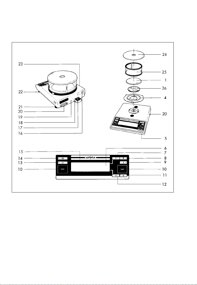
LC Series Balances with a Round Glass Draft Shield
1 Weighing pan
4 Draft shield base plate
5 Menu access switch
6 Weight display
7 f function key
8 w toggle key
9 Info key
10 Tare key
11 Print key p
12 F function key
13 c key
14 ON/OFF key e
15 Verification ID label with metrological
data for verified balances approved
for use as legal measuring instruments
1–2
16 Manufacturer’s label
17 Level indicator
18 Lug for attaching an antitheft locking device
19 AC jack/power receptacle
20 Data interface port
21 Leveling foot
22 Auxiliary foot
23 Metrological ID label
for verified balances approved
for use as legal measuring instruments
24 Draft shield lid
25 Glass draft shield cylinder
26 Pan support disk
Page 7
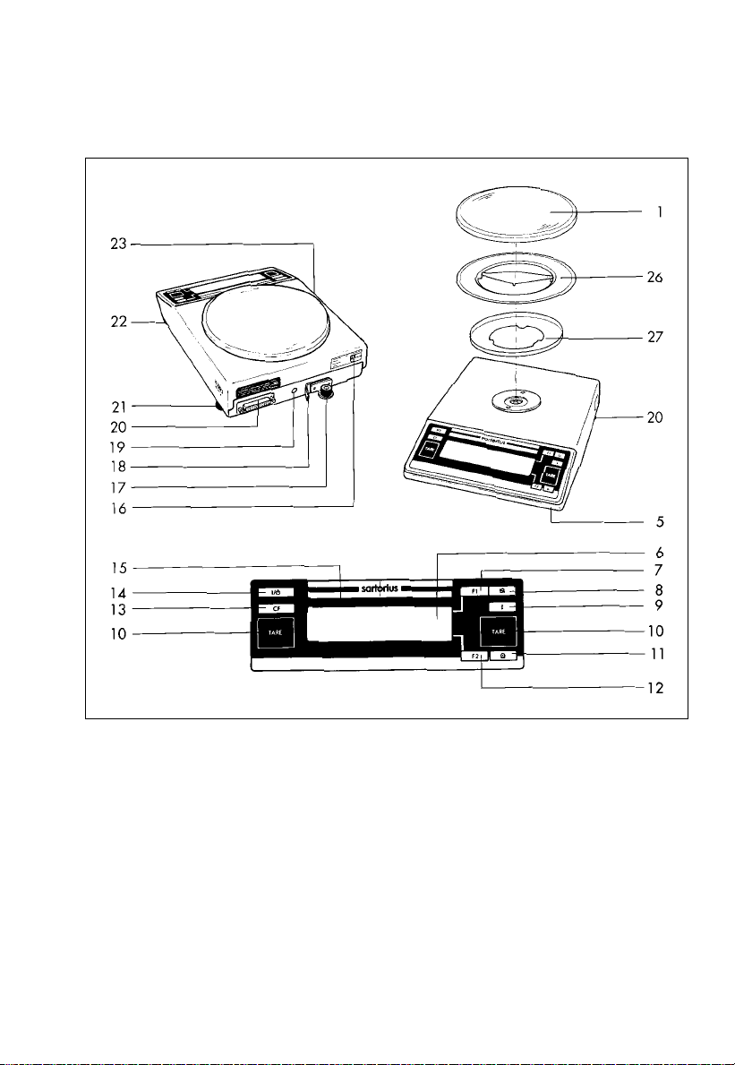
LC Series Balances with a Round Pan/GC1201-G
1 Weighing pan
5 Menu access switch
6 Weight display
7 f function key
8 w toggle key
9 Info key
10 Tare key
11 Print key p
12 F function key
13 c key
14 ON/OFF key e
15 Verification ID label with metrological
data for verified balances approved
for use as legal measuring instruments
16 Manufacturer’s label
17 Level indicator
18 Lug for attaching an antitheft locking device
19 AC jack/power receptacle
20 Data interface port
21 Leveling foot
22 Auxiliary foot
23 Metrological ID label
for verified balances approved
for use as legal measuring instruments
26 Pan support disk
27 Centering disk
1–3
Page 8
LC Series Balances with a Rectangular Pan
and a Capacity Less Than12 kg
1 Weighing pan
5 Menu access switch
6 Weight display
7 f function key
8 w toggle key
9 Info key
10 Tare key
11 Print key p
12 F function key
13 c key
14 ON/OFF key e
15 Verification ID label with metrological
data for verified balances approved
for use as legal measuring instruments
1–4
16 Manufacturer’s label
17 Level indicator
18 Lug for attaching an antitheft locking device
19 AC jack/power receptacle
20 Data interface port
21 Leveling foot
22 Auxiliary foot
23 Metrological ID label
for verified balances approved
for use as legal measuring instruments
28 Pan draft shield (metal frame,
depending on the model)
29 Dust cover
Page 9
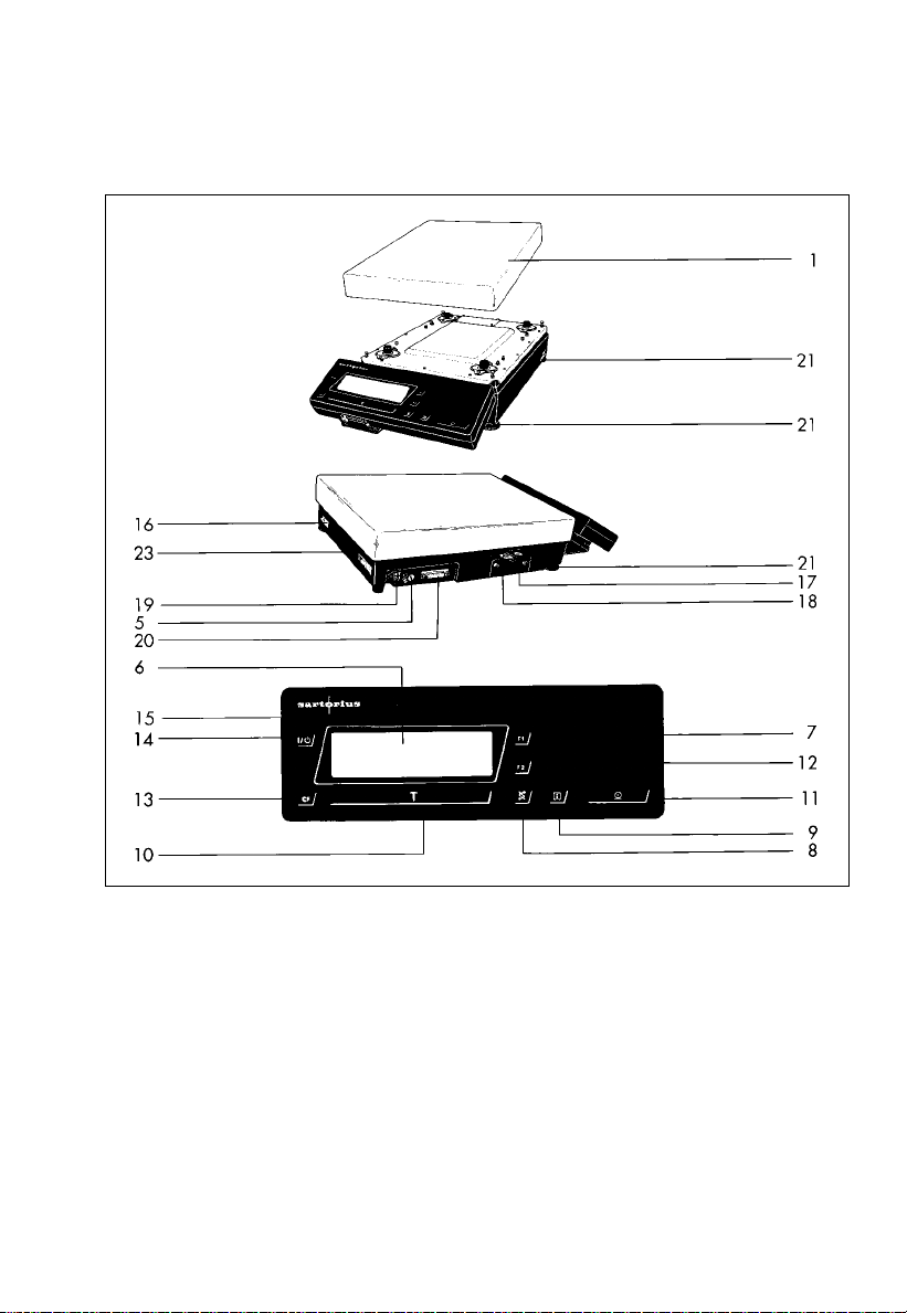
LC Series Balances with a Capacity Greater Than12 kg
1 Weighing pan
5 Menu access switch
6 Weight display
7 f function key
8 w toggle key
9 Info key
10 Tare key (labeled “TARE” on balance models
acceptable for verification)
11 Print key p
12 F function key
13 c key
14 ON/OFF key e
15 Verification ID label with metrological
data for verified balances approved
for use as legal measuring instruments
16 Manufacturer’s label
17 Level indicator
18 Lug for attaching an antitheft locking device
19 AC jack/power receptacle
20 Data interface port
21 Leveling foot
23 Metrological ID label (only for models
acceptable for legal metrological verification)
1–5
Page 10

With this Sartorius balance, you have acquired
a high-quality electronic weighing instrument that will
ease your daily workload.
Please read through these installation and
operating instructions carefully before operating
your new balance.
In the first part of these installation and operating
instructions, it is assumed that you are using the factoryset menu codes.
Warranty
Do not miss out on the benefits of our full warranty.
Please complete the warranty registration card,
indicating the date of installation, and return the card
to your Sartorius office or dealer.
Storage and Shipping Conditions
Allowable storage temperature:
+5°C ... +40 °C
+41°F ...+104°F
The packaging has been designed to ensure that
the balance will not get damaged even if it is dropped
from a height of 80 cm max. (about 32 inches).
Carefully unpack the balance and check the
equipment immediately for any visible damage
as a result of rough handling during shipment.
If this is the case, proceed as directed in the section
entitled “Safety Inspection.”
1–6
Save the box and all parts of the packaging in case
you need to ship your balance. For shipping your
balance, disconnect all cables before packing. Use
only the complete original standard packaging to
prevent damage to the equipment during shipment.
Do not expose the balance unnecessarily to extreme
temperatures, moisture, shocks, blows or vibrations.
Page 11
Installation Instructions
Ambient Conditions
Your Sartorius balance will provide accurate readouts
even when it is exposed to unfavorable conditions.
Please choose a suitable place to set up your balance.
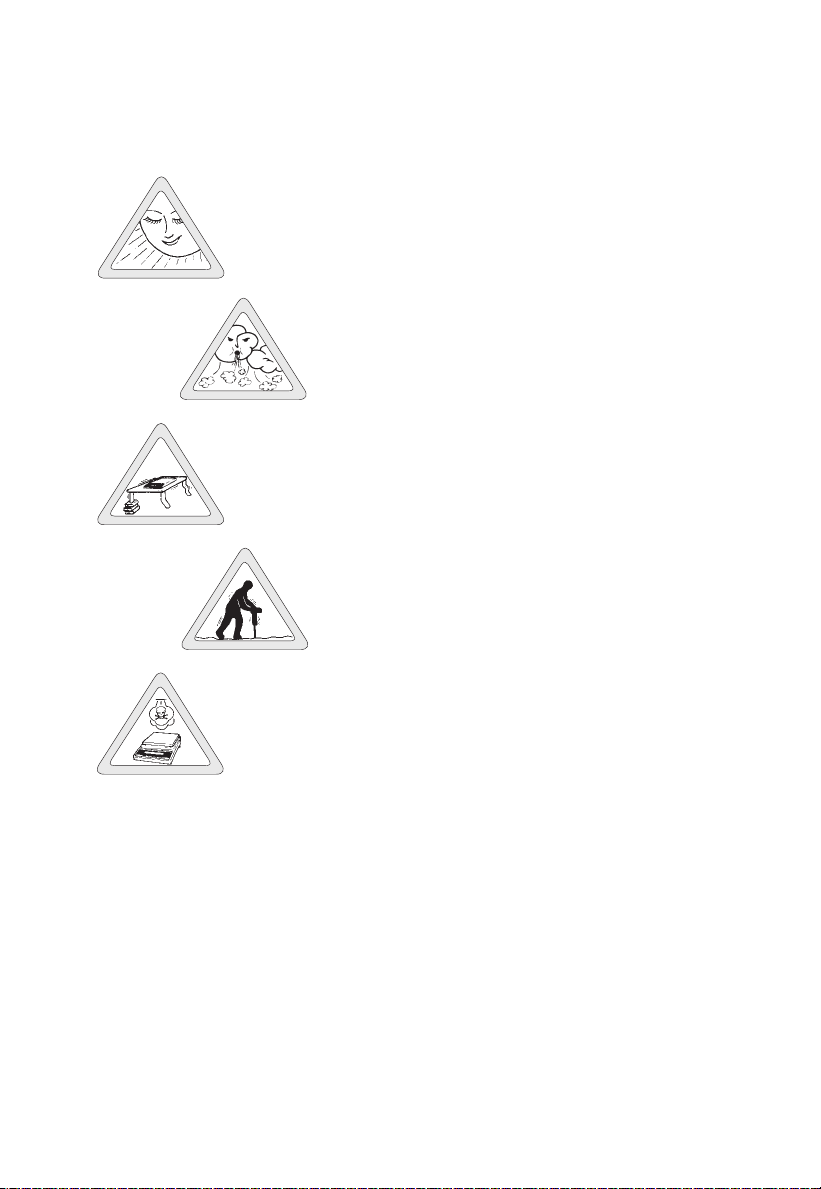
It should not be exposed to the following:
– extreme heat radiation
– drafts
– extreme vibrations
– aggressive chemical atmospheres
The balance may not be used in hazardous
areas/locations where there is danger of explosion.
Do not expose the balance to extreme moisture
over long periods. Moisture in the air can condense
on the surfaces of a cold balance whenever it is
brought to a substantially warmer place. If you transfer
the balance to a warmer area, make sure to
condition it for about 2 hours at room temperature,
leaving it unplugged. Afterwards, if you keep
the balance connected to AC power, the continuous
positive difference in temperature between the
inside of the balance and the outside will practically
rule out the effects of moisture condensation.
You can adapt the balance to your requirements
simply by changing the code settings in the balance
operating menu. For more information, please see
Part 2, “Balance Operating Menu.”
1–7
Page 12

Using Verified Balances as Legal Measuring
Instruments in the EU*
You must calibrate the balance at the place
of installation before using it as a legal measuring
instrument (see the section entitled “Adjustment/
Calibration” starting on page 1–19).
This balance is not allowed to be used for weighing
goods intended for direct sale to the public. The
type-approval certificate for verification applies only
to non-automatic weighing instruments; for
automatic operation with or without auxiliary
measuring devices, you must comply with the
regulations of your country applicable to the place
of installation of your balance. A suitable
thermometer and barometer are recommended for
monitoring ambient conditions.
For balances of accuracy class k, a thermometer
and barometer are recommended for monitoring
ambient conditions. The temperature range
indicated on the verification ID label must not be
exceeded during operation.
The balance must warm up for at least 24 hours
after initial connection to AC power or after
a relatively long power outage.
1–8
Sartorius complies with EC Directive No. 90/384/
EEC for non-automatic weighing instruments,
which has been in effect since January 1, 1993,
within the Single European Market, as well as
the accreditation of the Quality Management
System of Sartorius AG by Lower Saxony’s
Regional Administrative Department of Legal
Metrology (Niedersächsische Landesverwaltungsamt – Eichwesen) from February 15, 1993.
* including the signatories of the Agreement on the
European Economic Area
Page 13
Getting Started
Important Note Concerning All Verified Balances
Approved for Use as Legal Measuring Instruments
in the EU
Provided that an official seal is required for
the verified balance, a control seal is affixed to
the balance. Unauthorized attempts to remove this
seal will irreversibly damage it. If you break
the seal, the validity of the verification will become
void, and you must have your balance re-verified.
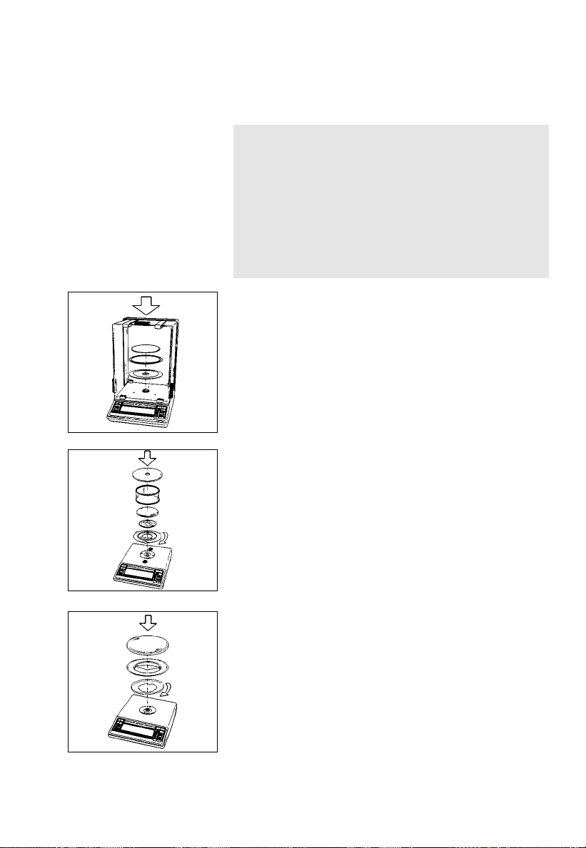
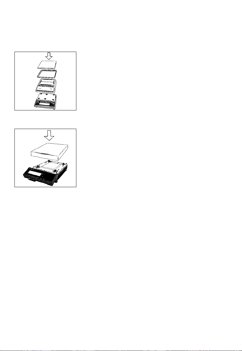
Preparing the AC Series Balance
In the following order, install the draft shield base
plate (4), the shield plate (3), the protective ring (2)
and the weighing pan (1) one at a time in the
weighing chamber.
Preparing the LC Series Balance
with a Round Glass Draft Shield
Place the draft shield base plate (4) on the balance.
Turn the plate clockwise until it snaps into place
(this procedure
for operation with or without a dust cover).
Mount the pan support disk (26), the weighing
pan (1), the glass draft shield cylinder (25) and the
draft shield lid (24) one at a time on the balance.
Preparing the LC Series Balance
with a Round Weighing Pan/GC1201-G
Place the centering disk (27) on the balance.
Turn the disk clockwise until it snaps into place (this
procedure is necessary for preparing the balance
for operation with or without a dust cover).
Then mount the pan support disk (26) and the
weighing pan (1) one at a time on the balance
in the order given.
is necessary for preparing the balance
1–9
Page 14
Preparing the LC Series Balance
with a Rectangular Pan and a Capacity Less Than12 kg
Remove the white backing from the adhesive strips on
the dust cover. Attach the dust cover to the base of the
balance by gently pressing down on the adhesive strips.
Place the pan draft shield (28) (depending on the
model) and the weighing pan (1) on the balance.
Important Note:
Double check to make sure that the base dust cover
does not touch the weighing pan.
Preparing an LC Series Balance
with a Capacity Greater Than 12 kg
Place the weighing pan (1) on the balance.
Connecting the Balance to AC Power
The balance is powered by an AC adapter.
Make sure that the voltage rating printed on this unit
is identical to that of your local voltage.
If the voltage specified on the label or the plug design
of the AC adapter does not match the rating or
standard you use, please contact your Sartorius office
or dealer.
Use only original Sartorius AC adapters. Use of
AC adapters from other manufacturers, even if these
units have an approval identification marking from
a national testing laboratory, requires the consent of
a certified Sartorius service technician.
1–10
Page 15
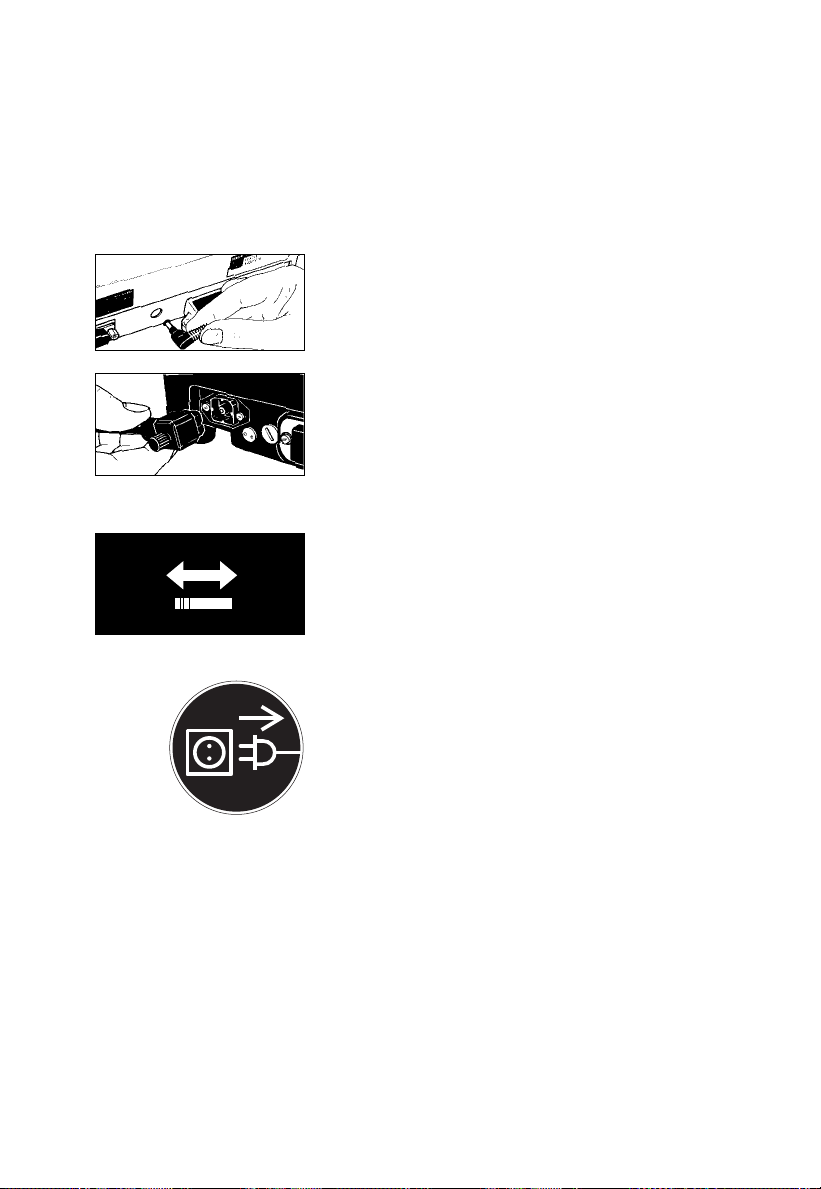
Plug the cord of the AC adapter into the balance.
230 V~ 115 V~
Then insert the plug of the AC adapter in a wall outlet.
Follow this procedure for the following balances:
AC and LC series balances with a capacity
less than12 kg
LC series balances with a capacity greater
than 12 kg:
Insert the right-angle plug in the power
receptacle (19) as shown, then tighten the slotted
screw with a screwdriver.
Now plug the AC adapter into a wall outlet.
Voltage Selection
(does not apply to balances with a capacity greater
than 12 kg)
You can select the voltage only if you use our portable
power supply (6971172) that has a European-type
plug (rounded prongs).
Connecting Electronic Devices (Peripherals)
Make sure to unplug the AC adapter from the wall
outlet before you connect or disconnect a peripheral
device (printer or PC) to or from the interface port
of the balance.
Safety Precautions
The AC adapter, rated to Class 2 (double insulation),
can be plugged into a wall outlet without taking
any additional safety precautions. The pole of the
output voltage is connected to the balance housing,
which can be grounded for operation.
The interface is also electrically connected to the
balance housing (ground).
1–11
Page 16

!
Information on Radio Frequency Interference
Warning!
This equipment generates, uses and can radiate radio
frequency energy and, if not installed and used in
accordance with the instruction manual, may cause
interference to radio communications. It has been
tested and found to comply with the limits for a Class
A computing device pursuant to Subpart J of Part 15
of FCC rules, which are designed to provide
reasonable protection against such interference, when
operated in a commercial environment. Operation
of this equipment in a residential area is likely
to cause interference, in which case the user, at his
own expense, will be required to take whatever
measures may be required to correct the interference.
Adjusting the Display Unit of an LC Series Balance
with a Capacity Greater Than 12 kg
Tilt the display unit to adjust it to the position
you desire.
1–12
Information on Weighing Electrostatically Charged Samples
Problems with static electricity can occur in
environments with low humidity. To avoid these
problems when you use your balance in such
an area, wipe down the entire draft shield on both
the inside and outside with a commercially
available antistatic agent.
If you need to use electrostatically charged glass or
plastic containers that have a relatively large diameter
with balances that have a readability of 0.1mg,
you should utilize our antistatic pan (155 mm Ø –
see “Accessories” in Part 6) instead of the standard
weighing pan.
Page 17
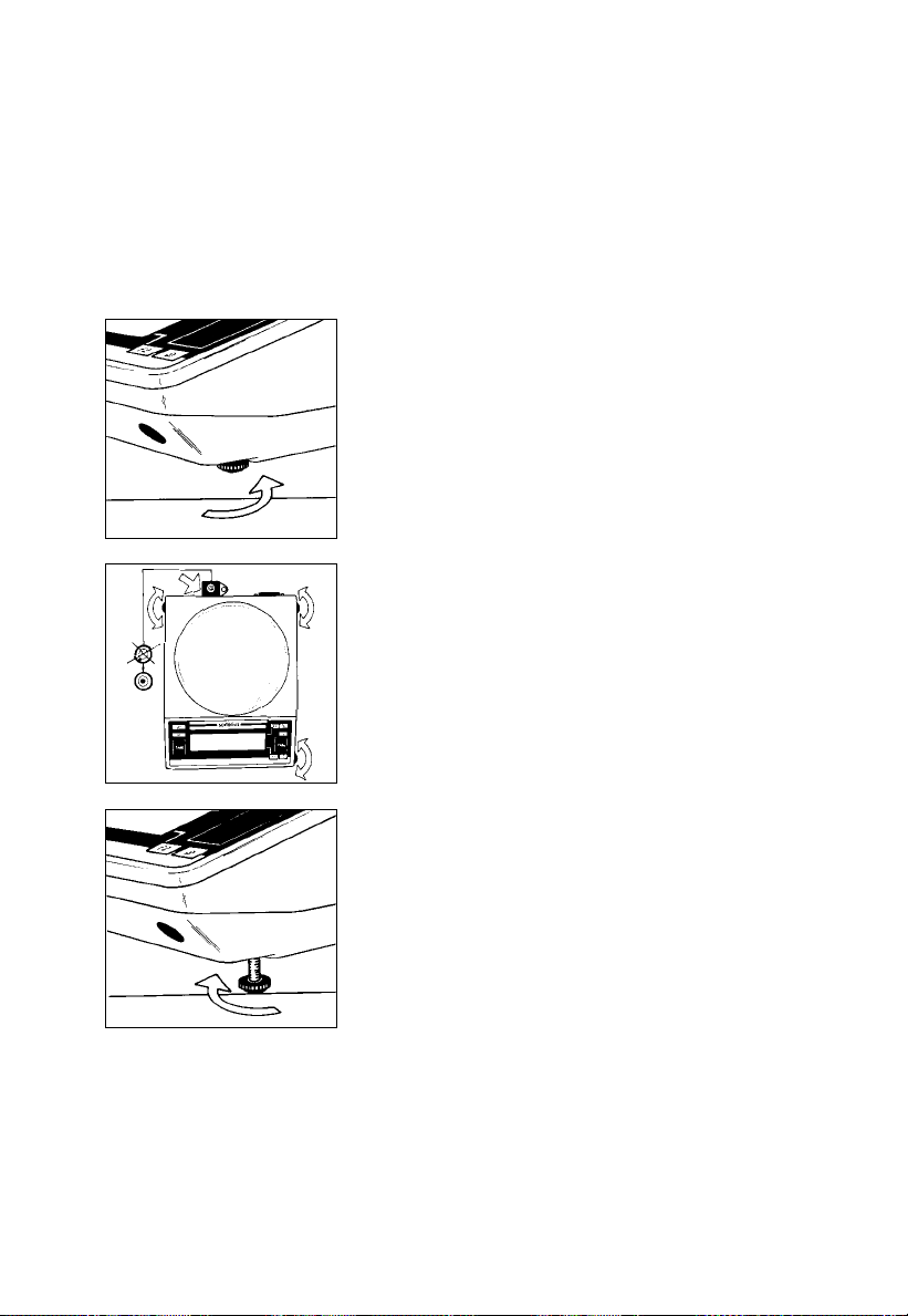
Leveling the Balance Using the Level Indicator
At the point of use, level the balance using the
leveling feet (21) as follows so that the air bubble is
centered within the circle of the level indicator (17):
Screw in the auxiliary foot (22) located on the front
right-hand side of the balance.
To level the balance using the level indicator
as a guide:
Extend the leveling feet (turn clockwise) to lift
the balance.
Retract the feet (turn counterclockwise) to lower
the balance.
Afterwards, extend the auxiliary foot (22) until it
touches
the surface on which the balance is resting.
1–13
Page 18
Operating the Balance
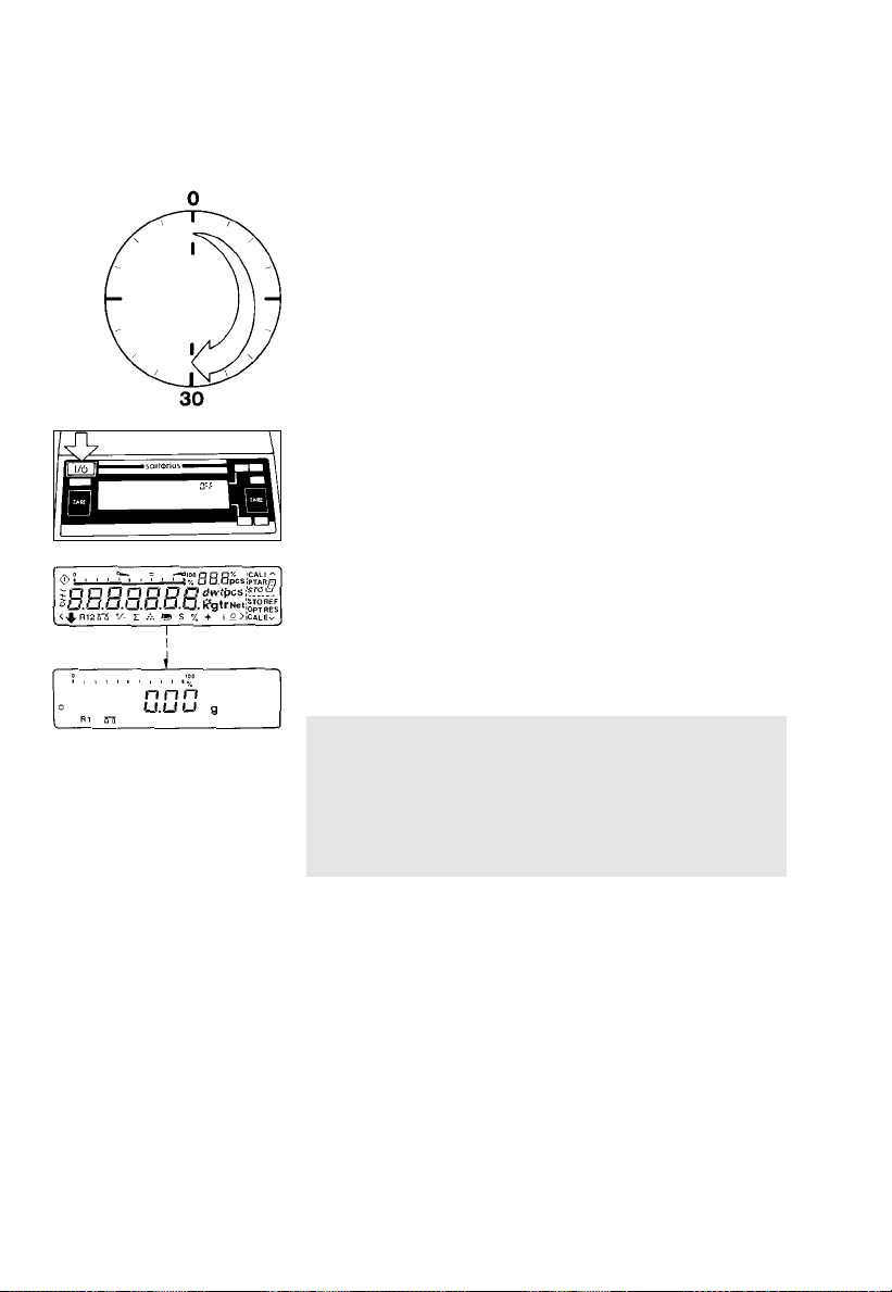
Warmup Time
After initially connecting the balance to AC power
(or after a relatively long power outage), the balance
will need to warm up for at least 30 minutes.
Turning the Display On and Off (Standby Mode) Press the e key (14) to turn the display on and off.
Self-Test
After the balance has been turned on, an automatic
self-test of theelectronic circuitry will be performed.
The self-test ends with a zero readout; the balance is
then ready to operate.
1–14
Important Note Concerning Verified
Balances/Scales Approved for Use as Legal
Measuring Instruments in the EU:
For verified balances that have a verification scale
interval “e” which is greater than the scale interval
“d,” the last digit on the display is bordered.
Page 19

The weight display shows the following special codes
for your information:
OFF
The balance was disconnected from AC power
(i.e., power failure or outage; the balance
was disconntected, then reconnected to AC power).
O (STANDBY)
The display has been turned off using the e key (14),
and the balance is now in the ready-to-operate mode
and does not require warmup.
b (BUSY)
Once you have turned on the balance, the b symbol
will remain displayed until you press a key. During
operation, this symbol indicates that the balance
processor is still busy processing a given function and
will not accept another command to perform any
other function at this time.
R1 or R2
The number in the R code identifies the particular
weighing range you have selected.
W
Symbol for the selected application (in this case, the
weighing mode).
CAL I
The balance has an internal calibration weight.
1–15
Page 20
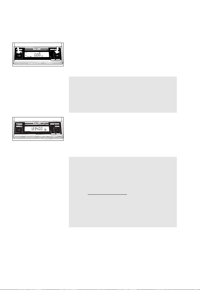
Taring
A weight can be accurately measured only from
a defined zero point. Press one of the two t keys (10)
to zero the display. You can tare the display within
the entire weighing range.
Important Note Concerning Verified
Balances/Scales Approved for Use as Legal
Measuring Instruments in the EU:
The small circle on the left in the weight display
shows that the balance/scale has been exactly
tared to “0” (±0.25 of a scale interval).
Weighing
Place your sample on the weighing pan (1) to
determine the weight. Read off the weight indicated
in the display (6) only once the weight unit/stability
symbol (“g”, “kg” or a different unit as selected – see
Part 2, “Balance Operating Menu”) is indicated.
Important Note Concerning Verified
Balances/Scales of Accuracy Class k
To avoid measuring errors, the respective air density
must be allowed for. The following formula is used to
calculate the mass of the sample:
m = n
1– ρL/8000 kg m
w
1– ρL/ρ
–3
1–16
m = mass of the sample
nw= weight readout
ρ
= air density during weighing
L
ρ = density of the sample
Page 21
6200g 0.01g
3200g
0.1g
Weighing Range Structure
SuperRange
(identified by S in the model designation AC/LC.....S)
“Single wide-range balance”
SuperRange models have an extraordinarily high
resolution; i.e., the weighing range has a resolution
ranging from100,000 to a few million digits. There is
one level of fine readability for the entire weighing
range (for example: 0.01g).
DualRange
(identified by D in the model designation LC.....D)
2 weighing ranges: a fine range and a standard range
1000g 0.01g
4800g
3000g
0.00g
1600g
800g
0.1 g
0.05g
0.02g
0.01g
The balance automatically switches from the fine range
which is10 times more accurate (e.g.1,000 g
capacity – 0.01g readability) to the standard range
(e.g., a 3,200 g capacity – 0.1 g readability)
when the balance is loaded beyond the fine range
limit (>1,000 g).
The weight readout is displayed with the lower
readability of the standard range until you tare in the
fine range (<1,000 g).
PolyRange
(identified by P in the model designation AC/LC.....P)
PolyRange models have a wide weighing range
with multiple levels of accuracy that change as the
load increases or decreases.
The PolyRange function divides the weighing range
into as many as 4 ranges, each with a different
readability. In the various ranges, the readability will
adjust so that the last numeral of a weight readout
is displayed with a resolution of 1, 2, 5 or 10 digits
(10 = only the next to the last numeral displayed
changes; the last numeral is blanked).
After you press the tare key (10), you will obtain
the highest possible resolution, even when the balance
is loaded.
1–17
Page 22
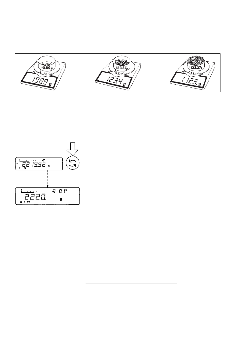
Weighing in the IQ-Mode*
(Load-Dependent Readability)
In the IQ-mode, weighing is done with a loaddependent readability of 0.1% (for different settings,
see part 2, “Balance Operating Menu”) throughout
the entire weighing range of the balance. The display
resolution of the last digit changes in increments of 1,2,
5,10, 20, etc., in proportion to the weight of a sample.
Oftentimes, a display accuracy of 2 grams
is sufficient for a load of approx. 2 kg. In this case, it
makes sense to select weighing range R 2 with an
accuracy of 0.1% by pressing the w key (8). While
you are filling up to a target weight, it is certainly
easier to work with a target of 2220 g than with an
absolutely accurate readout of 2219.92 g.
1–18
By selecting the IQ-mode for automatic adaption
of the display accuracy, you will obtain stable weight
readouts even faster.
In daily laboratory routines, analyses must often be
performed with a certain accuracy. The IQ-mode
meets this requirement – on an analytical balance, it
gives you the full accuracy of all 4 decimal places for
initial sample weights below1g, whereas for heavier
samples (of100 g or more), it provides a lower
readability, which is sufficient:
Initial sample weight Readout
Below 1 g → 0.9876 g
Above 100 g → 123.4 g
For other readabilities (0.01% – 1%) see page 2–11
of the “Balance Operating Menu.”
* = not applicable to verified balances approved for
use as legal measuring instruments in Europe; on
GC 1201G scales, menu code 3 2 9 must be set
Page 23

Adjustment/Calibration
During calibration1), the balance is adapted to
changes in ambient conditions.
You should recalibrate your balance each time you
set it up in a different area or when the ambient
conditions (such as the temperature or the barometric
pressure) have changed.
Independent of such changes, you should calibrate
balances acceptable for legal metrological
verification at least once a day (i.e., even when
the ambient conditions remain constant). To meet the
highest requirements for accurate weighing, we
recommend that you calibrate the balance before
each weighing series.
The balance offers you various calibration functions.
The function you select is indicated in the display
by one of the following codes:
“CAL” : calibration function is activated
“C– I” : internal calibration
“C– E” : external calibration
“C– t” : sensitivity test
“CAL I”: the balance has an internal
calibration weight
You can use the c key (13) to interrupt any
calibration process.
1
) “Calibration” technically means to determine
the difference between the balance readout and
the actual weight on the pan to determine the
accuracy. Adjustment means to bring a balance
into the state of accuracy required for its use.
Therefore, “calibration,” as used in this manual,
actually means “adjustment.”
1–19
Page 24

The balance may or may not have an internal
calibration weight:
– On standard balances, it depends on the model
(see Part 6, “Specifications”)
– Verified balances generally have an internal
calibration weight
Using Verified Balances/Scales as Legal
Measuring Instruments in the EU:
Before using your balance as a legal measuring
instrument, you must carry out an “Internal
Calibration” operation at the place of installation
after the warmup period.
1–20
Page 25
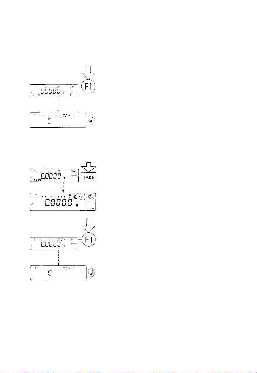
INTERNAL CALIBRATION
Quick-CAL Function Using the f Key:
Unload the pan and tare.
Once the display indicates a zero readout, press
the f key (7).
“C” will now be displayed. The built-in calibration
weight is internally applied by servomotor and
removed at the end of calibration.
If external interference affects the calibration
procedure, you may obtain a brief display of the error
message “Err 02.”
In this case, tare the display; then press the f key
again once a zero readout is indicated.
An acoustic signal indicates the end of calibration.
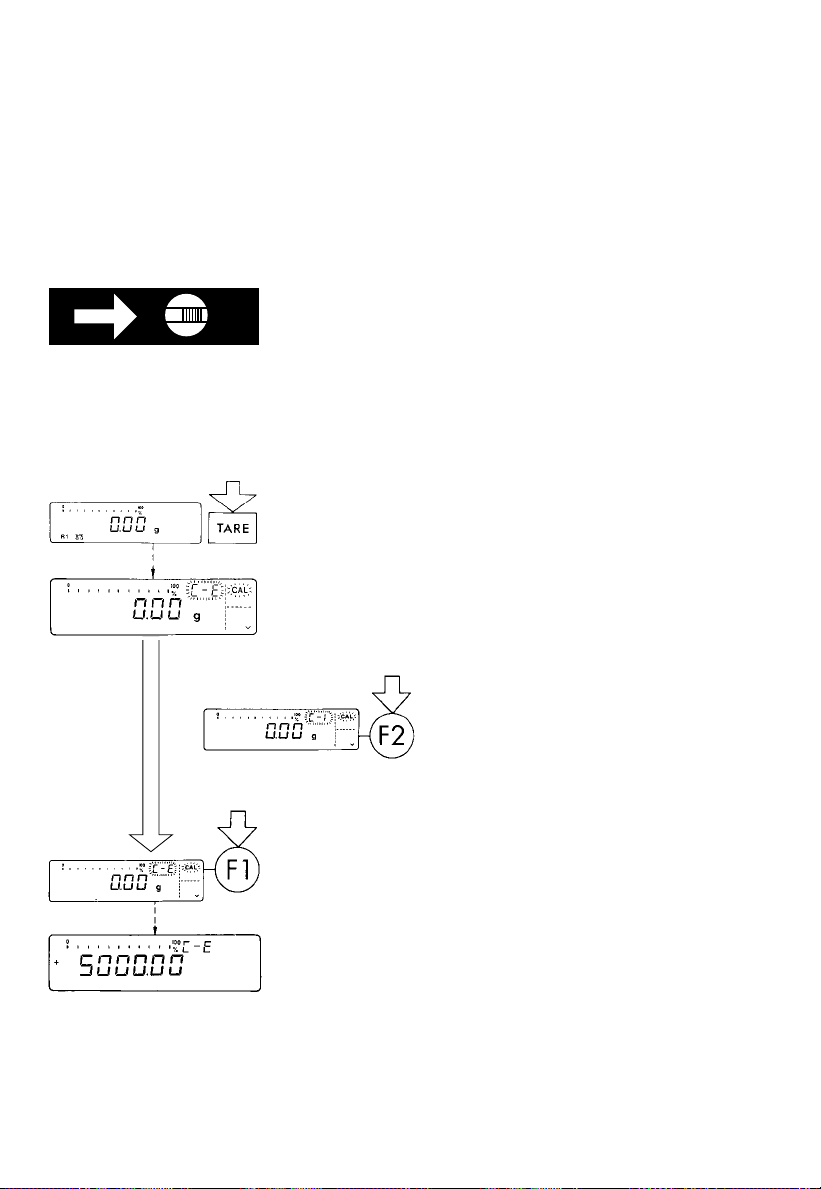
Internal Calibration Using the Tare Key:
2 sec.
Calibrate the balance using the tare control if an
application program (such as “tare memory”) is
assigned to the f key by menu code in the balance
operating menu (see parts 2 and 4).
Press the tare key (10) for at least 2 seconds until “C–I”
and “CAL” are displayed (next to the f key).
Unload the pan and tare.
Once the display indicates a zero readout, press
the f key (7).
“C” will now be displayed. The built-in calibration
weight is internally applied by servomotor and
removed at the end of calibration.
If external interference affects the calibration
procedure, you may obtain a brief display of the error
message “Err 02.”
In this case, tare the display; then press the f key
again once a zero readout is indicated.
An acoustic signal will indicate the end of the
calibration process.
!
Important Note:
The weighing pan must be left unloaded when using
the internal calibration function.
1–21
Page 26
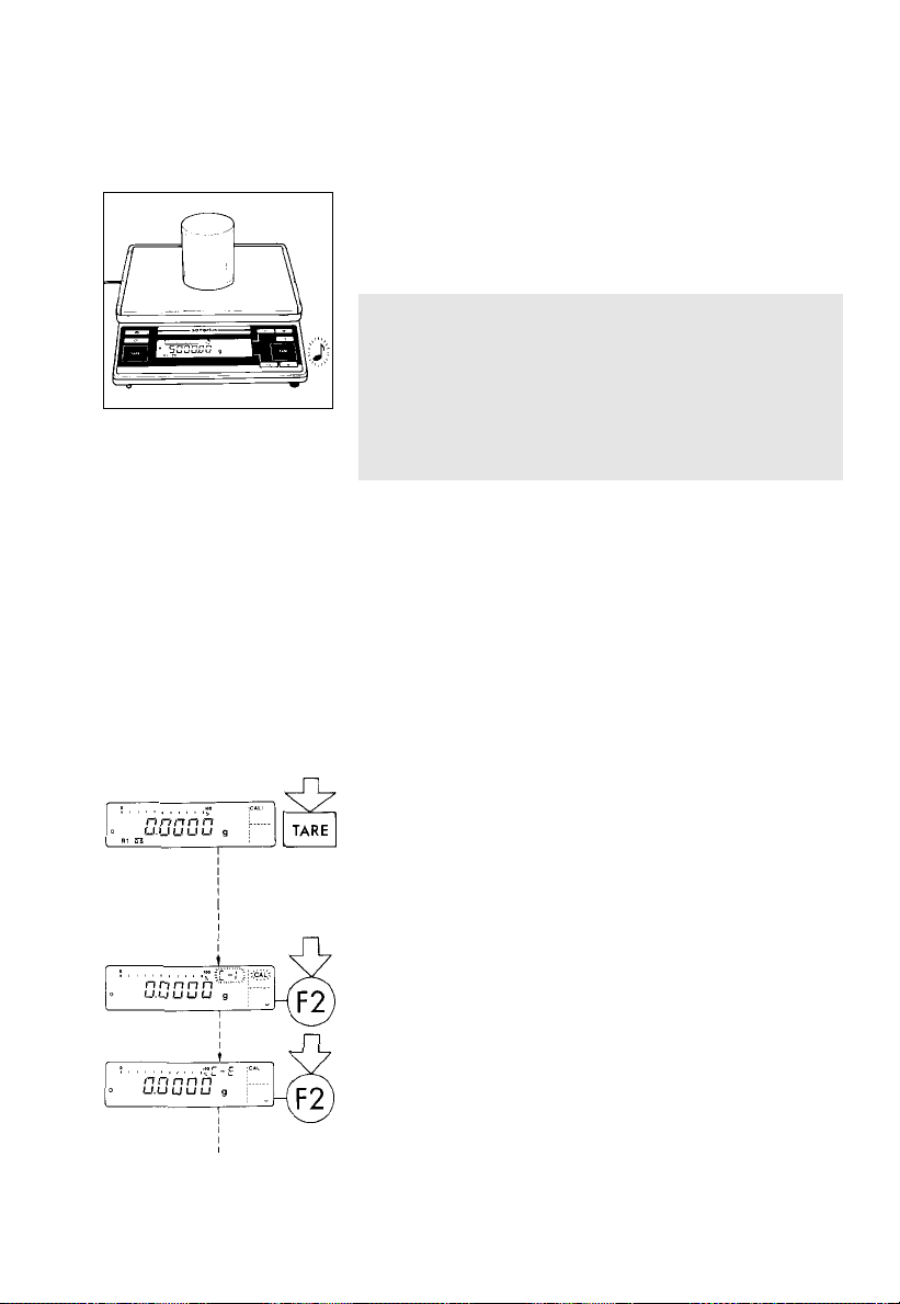
EXTERNAL CALIBRATION*
Use only calibration weights with the same
or better accuracy than that of the readability of your
particular balance.
Unlocking the Access Switch on Verified Balances/
Scales of Accuracy Class k:
– on balances with a capacity less than 12 kg,
remove the protective cap (5) on the front, right-hand
side of the unit
– on balances with a capacity greater than12 kg,
remove the large screw (5) located on the left-hand
side of the rear panel
– move the switch (5) in the direction of the arrow
2 sec.
Press the tare key (10) for at least 2 seconds until
“C– E” or “C– I” (only for balances with an internal
calibration weight) and “CAL” are displayed
(next to the f key).
Important Note:
If you press the f key (7) while “C–I” is displayed,
this will activate the internal calibration function.
For external calibration of balances
with an internal calibration weight,
press the F key (12).
1–22
“C– E” stands for “external calibration.”
Unload the balance and tare.
Press the f key (7) once a zero readout is
indicated. Afterwards, the calibration weight readout
will be indicated.
If external interference affects the calibration
procedure, you may obtain a brief display of the error
message “Err 02.”
In this case, tare the display; then press the f key
again once a zero readout is indicated.
* =
For accuracy class K verified precision
balances/scales, this function is allowed to be
used only if the balance is not being operated
as a legal measuring instrument.
Page 27
Center the calibration weight on the weighing pan.
An acoustic signal will indicate the end of the
calibration process.
Important Note for Accuracy Class K
Verified Balances/Scales Approved for Use
as Legal Measuring Instruments in the EU:
After verification, the “external calibration” function
is blocked by the access switch (5) (adjusted
to the left and secured against alteration of the
switch setting).
SENSITIVITY TEST (special function for balances
with a built-in calibration weight)*
Rather substantial changes in barometric pressure
and temperature may affect the display response
of these highly accurate balances. To ensure that you
obtain the full accuracy of these balances, even
when you use the entire weighing range, we have
implemented a sensitivity test function. It will help
you decide quickly whether or not you need to
recalibrate your balance (for example, to maintain the
same accuracy during long-term weighing series).
2 sec.
Press the tare key (10) for at least 2 seconds until
“C– I” and “CAL” are displayed (next to the f key).
Select the sensitivity test by pressing the
F key (12) twice.
* = Not on verified LC balances
1–23
Page 28
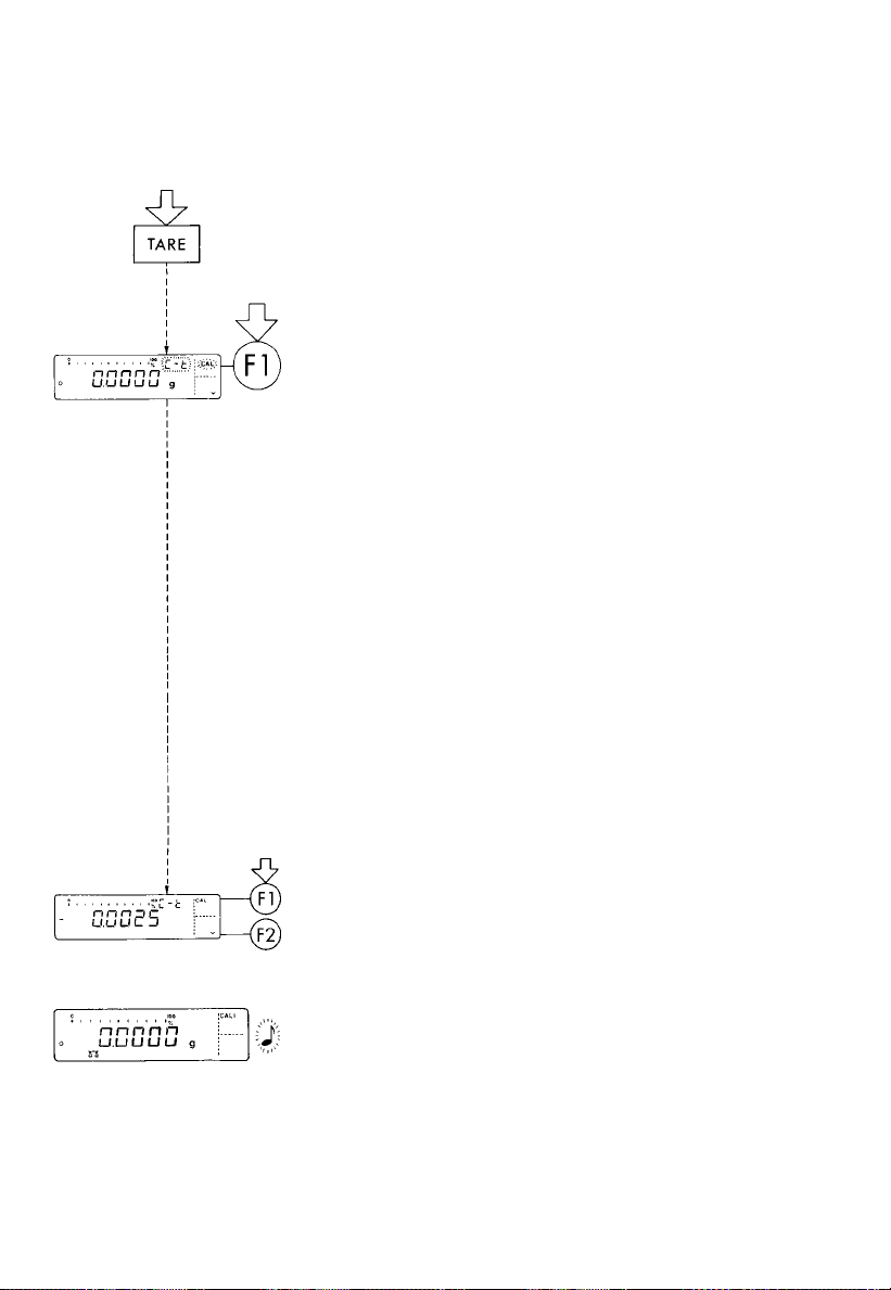
Unload the balance and tare.
“C– t” stands for “calibration sensitivity test.”
Once the display indicates a zero readout, press the
f key (7). The built-in calibration weight will now
be internally applied by servomotor. Then the
deviation of the current readout from the target weight
(displayed in grams only) will be indicated.
If external interference affects the calibration test,
you may obtain a brief display of the error message
“Err 02.”
In this case, tare the display; then press the f key
again once a zero readout is indicated.
Important Note:
The balance/scale should be calibrated if the
deviation of the readout from zero is more than the
reproducibility specified for standard balances
and more than the verification scale interval specified
for balances/scales acceptable for verification.
For reproducibilities and verification scale intervals,
see the “Specifications” that apply to your balance/
scale in Part 6.
1–24
f key: The balance is automatically
calibrated by the built-in
weight (see also page 1–21).
or
F key: Quits the sensitivity test
An acoustic signal will indicate the end of the
sensitivity test.
Important Note:
For information on the setting for “Quick-CAL sensitivity
test using f,”see Part2,“Balance Operating Menu.”
Page 29
Data Interface
If you wish to record your weighing results using
a Sartorius Data Printer, plug the printer connector into
the interface port (20) of the balance.You do not
need to adjust any settings.
Important Note for Balance/Scale Models Verified
for Use as Legal Measuring Instruments:
When using the balance/scale as a legal
measuring instrument (legal for trade), you are
allowed to connect to it only peripherals authorized
by law. However, if you are not using the
balance/scale as a legal measuring instrument, you
may connect to it any peripherals you wish, e.g.,
additional displays, personal computer, etc. Such
peripherals must be marked to indicate that they are
not allowed to be used when the balance/scale is
being used as a legal measuring instrument.
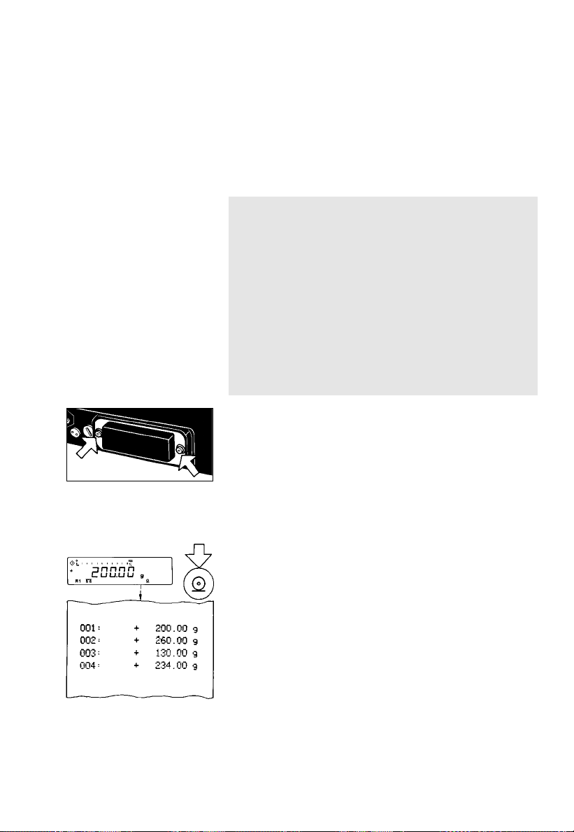
Remove the protective cap from the data
interface port.
Caution:
Make sure to unplug the AC adapter from the wall
outlet before you connect or disconnect any
peripherals (printer or PC) to or from the interface port
of the balance.
To print data on hard copy or have them output onscreen on an on-line computer, press the p key (11).
For information on special data output parameters,
see “Utilities” in Part 2.
For details on the data interface (such as the
data output or input formats, pin assignment, etc.)
or on interfacing a remote display, see Part 5,
“Interface Description.”
1–25
Page 30

Interfacing Devices with the Balance
Please note that the interface port is electrically
connected to the protective grounding conductor
of the balance housing. The interface cables supplied
as standard equipment are shielded, and both ends
of each cable are electrically connected to the
connector cases. This connection may result in interference caused by ground loops or by transient
currents if you have grounded the housing or
connected the protective grounding conductor
for line power. If necessary, connect an equipotential
bonding conductor to the balance.
1–26
Page 31

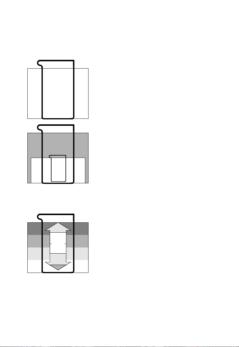
Below-Balance Weighing
A port for a below-balance weighing hanger is
located on the bottom of the balance (for LC balances
with a capacity greater than 12 kg, see “Accessories”
in Part 6).
To fasten the hanger, open the below-balance port by
turning the cover plate.
Now you can attach a sample to the hook using a
suspension wire, for example. Common applications
for below-balance weighing include density
determination or immersing a sample in a special
atmosphere (medium for reaction).
When you use such below-balance weighing
hangers, you must install a draft shield (especially
on analytical balances).
Important Note for Verified Balances/Scales
Approved for Use as Legal Measuring Instruments
in the EU:
When a verified balance/scale is being used
as a legal measuring instrument, the below-balance
weighing port may not be opened.
Fastening an Antitheft Locking Device
To fasten an antitheft locking device, use the lug (18)
on the level indicator case of the balance.
Set up your balance at the point of use, and secure it
using a chain or lock.
1–27
Page 32

Troubleshooting Guide
Problem ... Causes ... Solution
No segments – No AC power is available – Check the AC power supply
are indicated – The AC adapter is not – Plug in the AC adapter
in the weight plugged in
display (6) – Thebalance was discon- – Press the e key (14)
nected from AC power while
in the standby mode “o” or
turned “off” (display
backlighting turned off) and
was reconnected to AC
power <2 minutes later
The display – The weighing pan (1) – Position the pan
indicates “L” is not in place
The display – The load exceeds – Unload the balance
indicates “H” the capacity of the balance
The display briefly – A zero readout was not indi- – Press the tare key (10);
indicates “Err 02” cated when the f key (7) then press the fkey again
was pressed to calibrate
– The balance is loaded – Unload the balance
The special code – The balance is not – After connecting the balance
“C” displayed ready to calibrate or is in to AC power via the
does not go out the warmup phase AC adapter, let the balance
warm up for at least 30 min.
– The weighing system – Access the menu to
is affected by select the appropriate
drafts or vibrations code to adapt the balance
to the particular weighing
environment (see Part 2)
– The draft shield is – Check the draft shield
not closed (place the lid (24) on the
shield or close the doors of
the draft shield chamber)
The weight – The balance has not – Calibrate
readout is been calibrated (see pages 1–19ff.)
obviously – The balance was not – Tare before weighing
wrong tared before weighing
– The air bubble of the – Level the balance
level indicator (17) is not (see page 1–13)
centered within the circle
1–28
Page 33

Problem ... Causes ... Solution
The special – No keys have been – Press any key
code “b“displayed pressed since the balance
does not go out was turned on
The weight – Unstable ambient – Set up the balance
readout changes conditions in another area
constantly – Too much vibration or – Access the menu to
the balance is exposed select the appropriate
to a draft code to adapte the balance
to the particular weighing
environment (see Part 2)
– A door of the draft – Make sure that all
shield chamber is not draft shield doors
completely closed are closed
(only applies to draft shields
with sliding doors)
– The round glass draft – Position the round
shield is not in place draft shield
– The draft shield base – To mount these components,
plate (4) or the cen- see “Getting Started”
tering disk (27) is on page 1–9
not mounted correctly
– The dust cover for – Press down on the adhesive
balances with a rectangular strips to attach the dust cover
pan is not attached correctly
and is touching
the weighing pan
– A foreign object – Remove foreign object
is caught between the
pan and the housing of
the balance
– The cover plate for the – Turn the cover plate to
port for the below-balance close the port for
weighing hanger below-balance weighing
has not been closed
– The sample does not
have a stable weight
(absorbs moisture or
evaporates)
1–29
Page 34

Care and Maintenance
Servicing
Regular servicing by a Sartorius service technician
will extend the service life of your balance and insure
its continued weighing accuracy. Sartorius can
offer you service contracts with your choice of regular
maintenance intervals ranging from1month to 2 years.
Cleaning
Before cleaning the balance, unplug the AC adapter
from the wall outlet (mains supply).
Please do not use any aggressive cleaning agents
(solvents or similaragents). Instead, use a piece of cloth
which has been wet with a mild detergent (soap).
If your balance has a round glass draft shield,
avoid generating static electricity by wiping and
rubbing the glass. After cleaning, decharge the round
glass draft shield to eliminate static electricity, for
example, by wiping off all surfaces with a damp and
grounded piece of cloth.
Make sure that no liquid enters the balance housing.
After cleaning, wipe down the balance with a soft,
dry piece of cloth.
1–30
Changing the Dust Cover for LC Series Balances
If the dust cover is dirty, change it as follows:
– for round weighing pans (with or without a
round glass draft shield)
Remove the following parts from the balance:
– Draft shield lid (24)
– Glass cylinder (25)
– Weighing pan (1)
– Pan support disk (26)
Turn the centering disk (27) or the draft shield base
plate (4) until it snaps out of place and lift it off.
Then exchange the old dust cover for the new one.
Place the centering disk or the draft shield base plate
on the balance. Turn the disk or plate clockwise
until it snaps into place.
Page 35

– forrectangular weighing pans with a capacity <12kg
Remove the following parts from the balance:
– Weighing pan (1)
– Pan draft shield (28) (depending on the model)
Detach the dust cover by peeling it off at the adhesive
strips. Remove all traces of adhesive.
Then remove the white backing from the adhesive
strips on the new dust cover. Attach the dust cover by
gently pressing down on the adhesive strips.
Safety Inspection
If there is any indication that safe operation of the
balance with the AC adapter is no longer warranted,
turn offthe power and disconnect the equipment from
AC power immediately. Lock the equipment in a secure
place to ensure that it cannot be used for the time being.
Safe operation of the balance with the AC adapter
is no longer ensured when
– there is visible damage to the AC adapter
– the AC adapter no longer functions properly
– the AC adapter has been stored for relatively
long periods under unfavorable conditions.
In this case, notify your nearest Sartorius Service
Center or the International Technical Support
Department based in Goettingen, Germany. Only
service technicians who are authorized by Sartorius
and have access to the required maintenance manuals
are allowed to perform maintenance and repairwork
on the equipment.
We recommend that the AC adapter be regularly
inspected by a qualified Sartorius service technician
according to the following checklist:
– Insulation resistance >7 megohms measured
with a constant voltage of at least 500 V
at a 500 kohm load
– Equivalent leakage current <0.05 mA measured by
a properly calibrated multimeter
1–31
Page 36

Manufacturer’s Declaration
Electronic Balances AC.....-.... BA.....-..... BP.....-..... C.....-.....
and Scales (Series): CM.....-..... F.....-.... GA.....-..... GC.....-.....
I.....-..... IC.....-..... L.....-..... LC.....-....
MC.....-..... PMA.....-..... PT.....-.... QS.....-....
RC.....-..... S.....-..... TS.....-..... XX.....-.....
Remote Displays: 737101A 737102A
Data Printers: YDP01PT YDP02-0DV1 YDP02-0CEV2 YDP02-0CEV3
Rechargeable Batteries: YRB01PT YRB01Z YRB02Z YRB03Z
YRB04Z YRB05Z
T-Connector: 7258
Foot, Hand Switches: YPE01RC YPE01Z 7226 7252
Pursuant to the European Directive 73/23/EEC, particularly to Article 10,
we declare that the above listed equipment is manufactured and tested in accordance
with the following European Standards in force at the date of manufacturing.
Standards:
EN 60742 Isolating transformers and safety isolating transformers;
Requirements
EN 60950 Safety of information technology equipment including
electrical business equipment
If you use electrical equipment in installations and under ambient conditions
requiring higher safety standards, you must comply with the provisions as specified
in the applicable regulations for installation in your country.
Warranty and liability claims under civil law are not covered by this declaration.
Sartorius AG
D-37070 Goettingen, Germany
March 3,1994
OA-113-8/12.93
1–32
Oldendorf Dr. Maaz
Page 37

Balance Operating Menu
This Sartorius balance can do much more than “just weigh.”
It can “think” in various units of measure, adapt to unfavorable conditions and
process weight data for a variety of applications.
In the operating menu, you can define how your balance will adapt to ambient
conditions, and also how it will work to meet your special requirements.
For your convenience, the menu codes have been factory-set so that you normally
do not have to make any changes. If you have special operating conditions,
adjust the balance to your individual requirements by setting the menu codes of
your choice.
The factory-set menu codes are identified by an “*.” You can select the functions not
identified by an “*” by setting the respective menu code.
Don’t worry!
Even if you’ve selected the “wildest” codes and totally thrown off all the code
settings you need, all you have to do is press a key to set things straight again.
Your balance will work just like it did when it left the factory – with the original
factory-set menu codes.
Important Note for Verified Balances/Scales Approved for Use as Legal
Measuring Instruments in the EU:
The balance/scale operating menu can also be changed when the balance/
scale is being used as a legal measuring instrument (legal for trade). As a rule,
codes that are not permitted for operation of the balance/scale as a legal
measuring instrument
verified balances/scales cannot be locked with the menu access switch
(“–” not displayed).
are blocked or not displayed. The operating menu on
2–1
Page 38

Changing a Menu Code Setting
To select specific functions, you will need to set the
respective menu code.
There are three steps to changing a code setting:
– Accessing the menu
– Setting a code
– Confirming and storing the code
The keys have special functions for setting a menu
code. To set a code, use the four keys which are
defined on the display as arrow points to indicate
the direction:
<
w and > p = to move to the left and right
f and v F = to increase and decrease
^
a number by one with each press
t* = to confirm a code setting
c = to store a code setting and exit
the menu
Now try changing the weight unit in the second
weighing range from grams to “kg,” code 3 1 3.
Accessing the menu
– Turn the balance off
– Turn it back on again
2–2
– While all segments are displayed, briefly press the
tare key* (10)
– If -L- is displayed, unlock the menu as follows:
– on balances with a weighing range less than 12 kg,
remove the protective cap on the front, right-hand
side of the unit
– on balances with a weighing range greater than
12 kg, remove the large screw located on the
left-hand side of the rear panel to expose the menu
access switch (5)
– Move the switch (5) in the direction of the arrow.
* = Labeled “T” on standard LC series balances with
a capacity greater than 12 kg
Page 39

Press the f key to change the left-hand number
to “3”
– Press the p key to move to the middle number
– Now move from “1” to the right-hand number
(When you move to the right-hand number,
the previously set numeric code will be indicated).
– Press the f key to change the right-hand number
to “3”
– Press “TARE” to confirm the code setting
Important Note:
You must press the tare key in order to confirm
the code you have just set. This is indicated by the “o”
after the code.
– Press c to store the new menu code setting
The current code setting in the balance operating
menu is identified by a small “o” after the last number.
When you access the operating menu, the previously
set numeric code will be displayed after selecting
the left-hand and middle numbers, which means the
entire menu code setting is displayed. This makes
it easy for you to check the previously set menu codes.
If you would like to change several menu code
settings, you do not have to press c after each
change to leave the balance operating menu.
2–3
Page 40

Important Note for Standard Balances:
Please do not forget to relock the balance operating
menu. The “-L-” indicates that it is currently locked:
You can lock the menu anytime you wish once you
have accessed it. However, it is best if you wait until
you have changed the last code setting.
To use the locking function, make sure code 8 1 2 is
set in the balance operating menu.
If code 8 1 1 is set, the menu access switch will
not lock.
In this case, “-C-“ will be displayed whenever you
access the menu:
Undoing All Menu Code Changes: Reset Function
This function enables you to reset all menu codes
back to the original factory settings, which are
indicated by an “*” throughout part 2.
2–4
To activate this special function, set menu code
9 – – 1° and confirm by pressing t; press the c
key to store the code and leave the menu.
Reset function Code
Activated 9 – – 1
Off 9 – – 2
The charts on the next pages give just a small
sampling of the code options available for
the balance operating menu. These options involve
standard balance operation, utilities for printouts
or data transfer, and additional functions.
Page 41

Balance Operating Parameters
Adapting the Balance to Ambient Conditions
To adapt your balance to ambient conditions, you may need to change the
response time (see “Product Data Sheets”).
Code
Very stable conditions * 1 1 1
Stable conditions * 1 1 2
Unstable conditions 1 1 3
Very unstable conditions 1 1 4
Standard Weighing Mode – Manual Filling Mode
You can optimally adapt your balance to meet either of these requirements.
In the manual filling mode, the display compensates for fluctuations of the load
on the balance so that you obtain a steadier readout.
Code
Standard weighing mode * 1 2 1
Manual filling mode 1 2 2
Stability Range
The stability range in digits works together with the readout of the stability symbol
(unit symbol) when the load changes. When the stability symbol is displayed,
the weight readout is stable within the defined range.
Readout is stable within +/– Code
0.25 digit 1 3 1
0.5 digit * 1 3 2
1 digit2) 1 3 3
2 digits2) * 1 3 4
4 digits2) 1 3 5
8 digits1) 1 3 6
* = factory setting; depends on the balance model in some cases
1
) = not applicable to verified balances approved for use as legal
measuring instruments
2
) = not applicable to the verified AC models only
2–5
Page 42

Stability Symbol Delay
This setting allows your balance to compensate for individual interfering factors
which slowly subside, such as turbulent air currents generated within the weighing
chamber of an analytical balance. You can therefore choose to have the stability
symbol displayed later.
Code
No delay 1 4 1
Short delay * 1 4 2
Long delay 1 4 3
Extremely long delay 1 4 4
Tare Parameter
You can define when the balance will perform the taring operation:
Code
At any time ** 1 5 1
Not until the readout is stable * 1 5 2
Only at stability 1 5 3
Auto Zero Function
When this zero tracking function is activated, any changes off the zero readout
that are equal to a defined fraction of digits per second are automatically tared.
In other words, it ensures a stable zero.
Code
Auto Zero on * 1 6 1
Auto Zero off 1 6 2
* = factory setting
** = not applicable to verified balances approved for use as legal
measuring instruments
2–6
Page 43

Weighing in Three Ranges on Standard Balances
The toggle key, labeled w, lets you switch back and forth between two weighing
ranges, R1and R2, provided you are using the factory-set menu code.
When the menu code for “three ranges” is set, press the w key each time to
select a different range.
Selecting the Number of Ranges
Code
Block the w key/one weighing range 2 1 1
Two weighing ranges * 2 1 2
Three weighing ranges1) 2 1 3
For codes 2 1 4 “counting” and 2 1 5 “weighing in percent,” see part 4,
“Application Programs.”
Any range that you select by pressing the toggle key will always be indicated by
an ID code in the display. This ID depends on the menu code setting.
ID code
1st range 2nd range 3rd range
Two weighing ranges R1 R2
Three weighing ranges
– – –
** R1 R2
Weight Units
The “initial weight unit” is the unit in which your balance will weigh the moment you
turn it on. This unit is defined in the 1st range.
You can select a different unit for each weighing range by setting the appropriate
menu code.
Choose any weight unit you’d like, well almost any that’s reasonable for the
balance model you are using. For example, if you set the menu code for “kg”
on a 0.1 mg balance, you’ll obtain a readout sure enough, but the display
resolution might be slightly off.
* = factory setting
** = The standard weighing range automatically displayed when you turn on the
balance is identified by the scale pictogram in the display only.
1
) = factory setting on GC 1201-G scales only
2–7
Page 44

Overview of the Weight Units
Symbol Code
1st range 2nd range 3rd range
Grams o 1 7 1 3 1 1 3 3 1
Grams* g 1 7 2 3 1 2 3 3 2
Kilograms* kg 1 7 3 3 1 3 3 3 3
Carats ct 1 7 4 3 1 4 3 3 4
Pounds lb 1 7 5 3 1 5 3 3 5
Ounces oz 1 7 6 3 1 6 3 3 6
Troy ounces ozt 1 7 7 3 1 71) 3 3 7
Hong Kong taels tl 1 7 8 3 1 8 3 3 8
Singapore taels tl 1 7 9 3 1 9 3 3 9
Taiwanese taels tl 1 7 10 3 1 10 3 3 10
Grains gr 1 7 11 3 1 11 3 3 11
Pennyweights dwt 1 7 12 3 1 12 3 3 121)
Milligrams o 1 7 13 3 1 13 3 3 13
Codes 1 7 1, 3 1 1 and 3 3 1 are reserved for programming special units to meet
the needs of customized applications. The standard, factory-set unit is grams.
The “o” symbol will be indicated in the display as the stability symbol for a stable
readout, just as for milligrams.
Some unit symbols printed on hard copy or output on a computer screen will
differ from the way they are indicated in the balance display:
This applies to code numbers ending with 8 = tlh
9 = tls
10 = tlt
13 = mg
* = factory setting
1
) = factory setting on GC 1201-G scales only
2–8
Page 45

Weighing in Two Ranges on Verified Balances/Scales
Approved as Legal Measuring Instruments
The toggle key, labeled w, lets you switch back and forth between two weighing
ranges, R1and R2, provided you are using the factory-set menu code.
Selecting the Number of Ranges
Code
Block the w key/one weighing range 2 1 1
Two weighing ranges * 2 1 2
For codes 2 1 4 “Counting” and 2 1 5 “weighing in percent,” see part 4,
“Application Programs.”
Weight Units
The “initial weight unit” is the unit in which your balance will weigh the moment
you turn it on. This unit is defined in the 1st range. You can select a different unit for
each weighing range by setting the appropriate menu code.
Choose any weight unit you’d like, well almost any that’s reasonable for the
balance model you are using. For example, if you set the menu code for “kg”
on a 0.1 mg balance, you’ll obtain a readout sure enough, but the display
resolution might be slightly off.
Overview of the Weight Units
Symbol Code
1st range 2nd range
Grams g 1 7 2* 3 1 2*
Kilograms** kg 1 7 3* 3 1 3
** = factory setting; depends on the balance model in some cases
** = on LC balances only
2–9
Page 46

Display Modes on Standard Balances
You can select the display mode that best meets your individual requirements.
The factory-set menu code is defined for the highest possible accuracy in the
1st weighing range. The menu code settings for all weighing ranges are listed
on the next page.
Final Readout Mode
If you are interested in the final readout only, you can select this mode by setting
code 2 5 1. A special symbol, “– –,” will be displayed in any weighing range until
the final stable readout is indicated. For the standard readout mode, set code
2 5 2 (all readouts).
Special readout mode “– –” Code
Special symbol “– –” for unstable readings when load changes 2 5 1
Standard digital readout mode * 2 5 2
Last Numeral Blanked When the Load Changes
As the load on your balance changes, the display resolution is reduced by a factor
of 10 so that you will obtain a faster and more stable readout.
In the process, the last numeral is blanked until the load stabilizes. Once the load
has stabilized, the readout is indicated again with the full display accuracy, which
means the last numeral is displayed.
Round-Off Function
You can define the level of accuracy by changing the display increments, also
called “scale intervals” (of the last numeral). The display increments possible are
as follows: 1, 2, 5,10, 20, 50, etc.
Starting with the basic increments of a weight unit, the display accuracy can
be reduced by as many as three levels so that you will obtain a faster readout with
a reduced display accuracy. Display accuracy is reduced in relation to the
selected basic increment of the weight unit. Example: weight unit “ct” for carats
(5 increments) with code setting 1 8 3 →10 increments.
To make this concept easier to understand, the three levels are designated as
“rounding factors” in the tables summarizing the various menu code settings.
IQ-Mode
(Load-Dependent Readability)
In the IQ-mode, weighing is done with a menu-definable, load-dependent
readability throughout the entire weighing range of your balance. In the process,
the display resolution of the last digit of the weight value changes in increments
of 1, 2, 5,10, 20, etc., in proportion to the weight of the sample.
* = factory setting
2–10
Page 47

This mode for adapting the display accuracy enables you to weigh with a constant
relative accuracy between 1% and 0.01% over the entire weighing range
of your balance. Select the load-dependent display accuracy independently for
each of the three weighing ranges. The accuracy selected is shown in the top
right-hand corner of the application display field.
PolyRange Function (application for single-range balances) The PolyRange function divides a single weighing range into as many as
4 ranges, each with a different readability. In the various ranges, the readability
will adjust so that the last numeral of a weight readout is displayed with
a resolution of 1, 2, 5 or10 digits (10 digits = only the next to the last numeral
of the readout will change; the last numeral is blanked).
The PolyRange function makes filling easier because the readability becomes
slightly coarser as the load increases and you will not immediately lose an entire
place of readability.
Press the tare control at any range level to restore the full resolution of the first range,
even when the balance is loaded.
Code
Display mode 1st range 2nd range 3rd range
Highest possible accuracy * 1 8 1 3 2 11) 3 4 11)
Last numeral blanked when
load changes 1 8 2 3 2 2 3 4 2
Rounding factor 2 1 8 3 3 2 3 3 4 3
Rounding factor 5 1 8 4 3 2 4 3 4 4
Rounding factor10 1 8 5 3 2 5 3 4 5
1% accuracy 1 8 6 3 2 6 * 3 4 6
0.5% accuracy 1 8 7 3 2 7 3 4 7
0.2% accuracy 1 8 8 3 2 8 3 4 8
0.1% accuracy 1 8 9 *3 2 9 3 4 9
0.05% accuracy 1 8 10 3 2 10 3 4 10
0.02% accuracy 1 8 11 3 2 11 3 4 11
0.01% accuracy 1 8 12 3 2 12 3 4 12
PolyRange function 1 8 13 3 2 13 3 4 13
* = factory setting
1
) = factory setting on GC 1201-G scales only
2–11
Page 48

Display Modes on Verified Balances
You can select the display mode that best meets your individual requirements.
Final Readout Mode
If you are interested in the final readout only, you can select this mode by setting
code 2 5 1. A special symbol, “– –”, will be displayed in any weighing range
until the final stable readout is indicated. For the standard readout mode, set
code 2 5 2 (all readouts).
Special readout mode “– –” Code
Special symbol “– –” for unstable readings when load changes 2 5 1
Standard digital readout mode * 2 5 2
Last Numeral Blanked When the Load Changes
As the load on your balance changes, the display resolution is reduced by
a factor of 10 so you will obtain a faster and more stable readout.
In the process, the last numeral is blanked until the load stabilizes. Once the load
has stabilized, the readout is shown again with the full display accuracy, which
means the last numeral is displayed.
Code
Display mode 1st range 2nd range
Highest possible accuracy * 1 8 1 * 3 2 1
Last numeral blanked when load changes 1 8 2 3 2 2
IQ-Mode
(Load-Dependent Readability)
The IQ-Mode does not apply to verified balances approved for use as legal
measuring instrument.
* = factory setting
2–12
Page 49

Calibration Functions on Standard Balances
Select the appropriate menu code to define the access status for each of
the following calibration functions, which are activated by holding down the tare
key for a few seconds:
– External calibration C-E
– Internal calibration C-I
– Sensitivity test C-t
If the menu access switch is unlocked (“accessible” status indicated by -C- after
you have accessed the balance operating menu), the “external calibration”
function will be accessible even though you have set the menu code 1 9 2 for
“access denied.”
External calibration Code
Accessible * 1 9 1
Access denied 1 9 2
Internal calibration Code
Accessible * 1 10 1
Access denied 1 10 2
Sensitivity test Code
Accessible * 1 11 1
Access denied 1 11 2
Quick CAL Using f
If your balance has a built-in calibration weight, you can select the “internal
calibration” function at any time by a touch of the f key (factory setting:
accessible). That’s why we call it “Quick CAL” for short.
You can also set a different menu code to change the function of the f key from
“internal calibration” to “sensitivity test.”
Both functions are accessible even if you select code 1 10 2 or 111 2, respectively.
Function of the f key Code
No function * 2 2 1
Internal calibration (“CAL I”) * 2 2 5
Sensitivity test (“CAL T”) 2 2 6
For codes 2 2 2 to 2 2 4, see Part 4, “Application Programs.”
* = factory setting; depends on the balance model in some cases
2–13
Page 50

Calibration Functions on Verified Balances/Scales
Select the appropriate menu code to define the access status for each of
the following calibration functions, which are activated by holding down the tare
control for a few seconds:
– External calibration C-E
– Internal calibration C-I
– Sensitivity test C-t
External Calibration
Use the access switch to block or release the external calibration function.
External calibration
Accessible right
Access denied * left
On verified precision balances of accuracy class K, the “external calibration”
function is blocked by the access switch (adjusted to the left and secured against
alteration of the switch setting) after verification.
Quick CAL Using f
You can select the “internal calibration” function at any time by a touch of the f
key (factory setting: accessible). That’s why we call it “Quick CAL” for short.
On AC balances, you can also set a different menu code to change the function
of the f key from “internal calibration” to “sensitivity test.”
Function of the f key Code
No function * 2 2 1
Internal calibration * 2 2 5
Sensitivity test on AC balances 2 2 6
For codes 2 2 2 to 2 2 4, see Part 4, “Application Programs.”
Switch set to
* = factory setting
2–14
Page 51

Utilities for Printouts or Data Transfer
Sartorius balances come standard with an interface. You can plug a Sartorius
printer or a computer into this interface port to print data on hard copy or have
them transferred to your computer. Moreover, you can choose to output data from
your balance to this on-line device either automatically or by pressing the print
key on the balance.
The balance operating menu lets you define the various parameters for data output.
For information on the data formats and for interfacing a computer or other
peripherals, see Part 5, “Interface Description.”
Data Output Parameter
This parameter is coupled with the stability parameter =
stable readout or
no motion is detected
Print on request = data is output only when the print key is pressed or a software
command is received
Auto print = continuous, automatic data output
Code
Print on request regardless of stability 6 1 1
Print on request after stability with storage of the function * 6 1 2
Print on request at stability without storage of the function 6 1 3
Auto print regardless of stability 6 1 4
Auto print at stability 6 1 5
Automatic Data Output
You can stop and start automatic data output by pressing the print key.
To avoid operating errors or to ensure that data will be output continuously in the
automatic mode, you can block this function.
Code
Start/stop auto print using the p key 6 2 1
Auto print not stoppable * 6 2 2
* = factory setting
2–15
Page 52

Data Output at Defined Intervals
You can reduce the volume of data in the “auto print” mode by defining the interval
at which data will be output automatically. This auto print interval is based on the
number of display updates.
Auto print interval Code
1 display update * 6 3 1
2 display updates 6 3 2
5 display updates 6 3 3
10 display updates 6 3 4
20 display updates 6 3 5
50 display updates 6 3 6
100 display updates 6 3 7
Automatic Taring after Data Output
This convenient setting lets you checkweigh a series of samples or products
without having to unload the balance after each weighing procedure. This means
less work for you:
– the sample remains on the pan after the weight readout has been printed or
transferred to an on-line computer
– the balance is tared automatically after the weight readout has been printed or
transferred to an on-line computer
– you simply load the next sample or part
Code
Data output without automatic taring * 6 4 1
Data output with automatic taring 6 4 2
* = factory setting
2–16
Page 53

Data ID Codes
To help you identify weights, piece counts, percentages, etc., a code letter is
printed or displayed in front of these values. For example, an “N” printed or
displayed in front of a weight value identifies it as a net weight. If you set the code
for “without data ID code,” only net weights, results in percent and counting
results will be output. You will find the data ID codes of a particular application
program listed in the corresponding description. The ID code increases the data
output format for each weight readout from16 to 22 characters.
ID code for data output Code
Without * 7 2 1
With ** 7 2 2
** = factory setting
** = factory setting for the IAC version
2–17
Page 54

Additional Functions
A number of additional menu codes enable you to assign or deny access to various
functions.
Menu Access Function on Standard Balances
You can define the function of the menu access switch on standard balances
by setting the code for the balance operating menu to “accessible.”
Access to the balance operating menu with standard balances Code
Accessible 8 1 1
Depends on the setting of the menu access switch * 8 1 2
Menu Access Switch Function on Verified Balances of Accuracy Class K
The balance operating menu can also be changed when the balance is being
used as a legal measuring instrument. Codes that are not permitted for operation
of the balance as a legal measuring instrument are blocked and cannot be
selected. The balance operating menu on verified balances approved for use as
legal measuring instruments cannot be locked with the menu access switch (“–”
not displayed). For balances of accuracy class K, the menu access switch is
adjusted to lock the “External Calibration” function after verification. To do this, the
switch must be moved to the left. A control seal is affixed to the balance to lock
the menu access switch. Unauthorized attempts to remove this seal will irreversibly
damage it. If you break the seal, the validity of the verification will become void,
and you must have your balance re-verified.
Beep Tone (Acoustic Signal)
If you wish, you can turn off the beep tone (i.e., acoustic signal)
Acoustic signal Code
On * 8 2 1
Off 8 2 2
Blocking the Keys
You can block all keys on the balance (except for e) by setting the respective code.
Key functions Code
Accessible * 8 3 1
Blocked 8 3 2
* = factory setting
2–18
Page 55

Universal Switch for Remote Control
You can connect an external universal switch to the interface of your balance for
remote control of certain functions (listed below). Set the appropriate menu code to
define the function of this switch.
Functions Code
Print * 8 4 1
Tare 8 4 2
f key 8 4 3
F key 8 4 4
Analog Display: Bar Graph/Marker
In the factory setting, the analog display works as a bar graph. By changing
the menu code, you can turn the analog display completely off or have it appear
as a marker. When the marker is selected, two individual segments will move
within the display scale range to indicate the loading status of your balance.
Analog display Code
Off 8 5 1
Bar graph * 8 5 2
Marker 8 5 3
Power-On Mode
Depending on the operating mode, line current, battery operation or continuous
operation, you can change the power-on mode of your balance.
The factory setting is: (power) off –> on <–> standby.
In the setting “toggle between on and (power) off,” the balance remains off after
a power failure has occurred or after the balance has been disconnected from
AC power. After the balance has been turned off, power for the “standby” mode
is not available. In this setting, the balance can be turned on and off using
the e key.
* = factory setting
2–19
Page 56

In the setting “toggle between on and standby,” the balance power will turn back
on automatically after a power failure has occurred or after you have disconnected
your balance temporarily from AC power.
In the setting “automatic power-on,” the balance will turn back on automatically
after a power failure has occurred; after the balance has been disconnected, then
reconnected to AC power; or after the e key has been pressed. In this setting,
the balance can no longer be turned off using the e key.
Power-on mode Code
(Power) off –> on <–> standby * 8 6 1
On <–> (power) off 8 6 2
On <–> standby 8 6 3
Automatic power-on 8 6 4
Automatic Shutoff (Battery Saver) for Use with Code 8 6 2 or the
Rechargeable Battery Option**
If you are using the rechargeable battery option, turn the automatic shutoff function
on to increase the hours of battery operation so that you do not need to recharge
the batteries that often. Here is how the battery saver function works: If there has
not been a change in a weight readout for at least 2 minutes or you have not
pressed any keys during this time, “b” will be displayed. After another 2 minutes,
the balance will shut off if it has not been used in the meantime.
Automatic shutoff Code
On 8 7 1
Off * 8 7 2
Display Backlighting
Depending on your individual workplace requirements, you can turn the display
backlighting on or off accordingly.
Display backlighting Code
On * 8 8 1
Off 8 8 2
** = factory setting
** = not applicable to verified balances approved for use as legal
measuring instruments
2–20
Page 57

“isoCAL” Self-Calibrating Function*
on AC/LC…-00MS/-0CEMS Models
Range of Performance Features
The AC/LC…-00MS/-0CEMS models have
standard features which are not offered by other
balances and scales of the product line:
– Built-in servomotor for application of the internal
calibration weight(s)
– Self-calibrating function – “isoCAL”
– ISO/GLP-compliant printout/record
– Integrated Applications Computer “IAC” for the
application programs:
tare memory; formulation;
statistics; weighing in percent; counting; clock and
timer for time-controlled measurements/weighing;
calculation of weight values; totalling of weights;
averaging/animal weighing; density determination;
over/under checkweighing; ID number for
identification of data
Important Note for Verified Balances/Scales
(…-0CEMS):
These models are allowed to be used in the extended
ambient temperature range of 0°C to +40°C as
long as not otherwise indicated on the verification ID
label.
* = Balances of the product line cannot
be upgraded with this function
3–1
Page 58

“isoCAL” Self-Calibrating Function
A balance of the Master Series can self-calibrate.
The self-calibrating function is activated based on the following parameters:
Model When the tempera- After a calibration
ture changes interval of
AC 211S-00MS, AC 211P-00MS,
AC 121 S-00MS 1.5 kelvin 4 h
LC 3201 D-00MS, LC 1201 S-00MS 1.5 kelvin 4 h
LC 621 S-00MS, LC 621P-00MS,
LC 6201 S-00MS, LC 4201S-00MS,
LC 4801 P-00MS 2 kelvin 6 h
LC 221 S-00MS, LC 2201S-00MS,
LC 2201 P-00MS, LC 34000 P-00MS 4 kelvin 12 h
LC 821-00MS, LC 421-00MS,
LC 16000 S-00MS, LC 12001 S-00MS,
LC 6201-00MS, LC 4201-00MS,
LC 34-00MS 4 kelvin 24 h
These parameters are the same for the corresponding balance/scale models
that have been verified or are acceptable for legal metrological verification (models
AC/LC…-0CEMS).
In addition, the self-calibrating function is activated after an hour has passed
since the balance was connected to AC power (power on) and after an hour has
passed since the time was set.
If the balance self-calibrates due to a change in temperature, the timer for the
calibration interval is set back to zero. The timer for the calibration interval is also
active when the balance is in the standby mode. After the balance has been
turned on, a check is run to see if a calibration time was exceeded while the
balance was in the standby mode.
Flashing W Symbol
If the “W” symbol flashes, the balance wants to self-calibrate. You do not need to
interrupt your weighing series, because the balance will wait until you have
unloaded the weighing pan (at least to approx. 2% of maximum capacity) and
have not used the balance for two minutes. Then the balance will self-calibrate.
The W symbol flashes until the balance begins self-calibration or until you activate
the calibration function manually (see also “Calibration” in Part 1).
You can interrupt the calibration process at any time by pressing the c key.
If any external disturbance affects self-calibration, the error code “Err 03”
will be displayed, and the procedure will be interrupted by two beep tones.
After two minutes, the self-calibrating function will restart.
3–2
Page 59
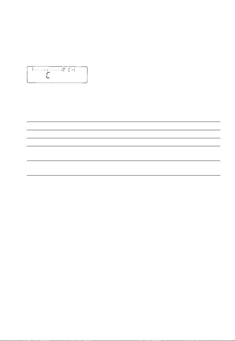
Important Note for Verified Balances/Scales Approved as Legal Measuring
Instruments (…-0CEMS):
If “C” is indicated in the display or “STAT C”
is output via the interface, the balance/scale must not
be loaded.
The balance/scale initiates self-calibration 15 seconds after “C” is indicated
in the display. Changing loads during these15 seconds will interrupt the internal
preparation cycle for calibration.
You can select the following menu codes:
Self-calibrating function – “isoCAL” Code
1)
OFF
1 15 1
Calibration symbol “W” in the display only1)2) 1 15 2
ON – “isoCAL” with clearing of values determined
for application programs3) 1 15 3
ON – “isoCAL” without clearing of values determined
for application programs *1 15 5
1
) Not applicable for verified balances/scales approved as legal measuring
instruments (…-0CEMS)
2
) When code 1 15 2 is set, the “W” symbol will flash in the display until you
activate the calibration function manually.
3
) Reference values for the application programs have to be stored once again
after self-calibration has been performed (e.g., for counting or weighing in
percent). Measured values calculated for statistics or totalling will be deleted
after the calibration process has been performed.
Activating Internal Calibration Manually
The “Quick-CAL” key functions and “Internal Calibration Using the Tare Key”
are described Part 1.
*= factory setting
3–3
Page 60

Automated Processes
Delays in production may occur when the “isoCAL” function is used in automated
processes. You can avoid such delays by setting menu code 1 15 2 “Calibration
symbol “W” in the display only.” In this case, you have to press the key to
activate calibration.
Printout or Record of Calibration Processes
The balance, interfaced with a data printer or a computer, creates a document
that records the date, time, serial number and model number which makes it
possible to clearly trace data to the balance that generated it. For more information,
see the section entitled “ISO/GLP-compliant Printout or Record” in the IAC
instruction manual.
Calibrating Balances When Using YDK 01, YWP 01, YWP 01U
or YWP 02 Accessories
When you use the YDK 01density determination kit or one of the special weighing
pans, YWP 01, YWP 01U or YWP 02, the balance cannot self-calibrate.
If the “W” symbol flashes, place the standard weighing pan on the balance and
activate the calibration function manually.
Self-Calibration with the MC1-MP8 Interface (Binary Converter)
EC-approved balance/scale models (…-0CEMS) can self-calibrate also when
menu code 9 2 3 for the MC1-MP8 interface (binary converter) has been set.
On all other models, if you select the MC1-MP8 interface, the balance cannot selfcalibrate. If this is the case, activate the calibration functions manually.
3–4
Page 61

Application Programs for Balances of the
Product Line
In addition to the functions implemented strictly for weighing, Sartorius balances
of the MC1 product line offer you a variety of application programs to handle
tough daily routine work in the laboratory as well as in industrial plants. If you have
not yet experienced how fast and accurately a Sartorius balance can count parts
or convert weights into percentages, now is a good opportunity to try it out.
In this description, you’ll find a few simple examples for the following applications:
Tare memory
Weighing in percent
Over/under checkweighing
Counting
You can also use “tare memory” and “over/under checkweighing” in combination
with “weighing in percent” or “counting.”
If your balance has a numeric keypad, please use the instructions entitled “IAC”
or “Backweigher” supplied with the balance.
4–1
Page 62

To select an application program or a specific function, set the appropriate code
in the menu. Part 2 describes in detail how to set menu codes.
Additional settings for running the particular program and displaying or printing the
data on hard copy are listed in a table of codes.
One thing you should do when you want to set the code for a different program,
or when someone else has already operated the balance is:
Select the reset function – code 9 – –1o– to change all menu codes back to the
original factory settings.
Using Verified Balances/Scales as Legal Measuring Instruments in the EU:
All application programs can be selected on balances used as legal measuring
instruments. Non-metric values are indicated as follows:
Percent = %
Piece count (counting) = pcs
Computed value = o
Functions Common to All Programs
The f, F and w keys are assigned different functions by the individual
programs. In each case, the functions currently assigned to the f and F keys
are always identified in the display next to each key.
c Key
c clears the program function and resets the program.
Clear function Code
Global – clears functions of all keys * 2 4 1
Selective clearing in the order of f → F 2 4 2
Use the selective code if you intend to run two different programs at the same time.
Select code 2 4 2 if you would like to clear the program assigned to the f key
before you clear the program assigned to the F key.
* = factory setting
4–2
Page 63

Information and Printouts or Data Transfer
The info key (i) has two functions:
– one brief press: displays information and prints/transfers stored data
– one long press: recalls the reference percentage or reference sample
quantity for weighing in percent or counting (for more
information, see the descriptions of these programs)
Briefly press the i key to select the information
function: an “i” will appear in the display.
If you press f or F now, the data stored in
the memory will be retrieved and displayed. What is
displayed depends on the program selected.
Example: Counting
Readout: Reference sample quantity
Readout: Reference sample weight
nRef + xxxxxxx pcs
wRef + xxxxxxx g
These data will also be output via the interface (printed
or transferred) if you press the p key after pressing
the info key. In this case, the print symbol will be
Data output only for
displayed next to the “i” until you press a function key.
Code 7 2 2
Info + function key → displays data stored in the memory
Info + print + function key → displays and prints data stored
For information on printouts or data transfer, see “Utilities” in Part 2. In the examples
in Part 4, the data that are output via the interface are printed on hard copy.
4–3
Page 64

Tare Memory
Press the f key (identified by “TAR” in the display) to store the tare weight.
Symbol displayed when a value is stored: Net
The balance will be tared automatically so you can weigh again starting with
a zero readout.
Display/Print Tare – Net – Gross Weights Code 2 2 2
Menu codes used in the example:
Function Code
Tare Memory 2 2 2
With data ID code 7 2 2
Automatic data output 7 1 2
Tare memory contents 7 3 2
Application: for obtaining printouts of tare, net and gross weights or outputting
these data to a computer
Step/(key ID)/key Readout Data output/printout
c, t
Place the container
on the pan +
Tare: (TAR) f
Fill container with
sample; p +
c, p +
The data ID codes mean:
T1 + 22.65 g tare weight stored in the memory
N1 + 250.24 g net weight when tare weight is stored
N + 272.89 g weight without stored tare weight = gross
As an alternative, you can select
this output parameter:
Data output – manual mode *7 1 1
0.00 g
22.65 g
0.00 g Net
250.24 g Net
272.89 g
T1 + 22.65 g
N1 + 250.24 g
N + 272.89 g
*= factory setting
4–4
Page 65

Net Total Code 2 2 2
Press f (identified by “TAR” in the display) to store each component that you
weigh-in. The balance is tared automatically each time you store a weight.
Therefore, you can weigh-in the components one after the other starting with
a zero readout.
Menu codes used in the example:
Function Code
Tare memory 2 2 2
With data ID code 7 2 2
Automatic data output 7 1 2
Printout of individual
components/tare weights *7 3 1
Application: simple compounding and formulating in the lab or in production
Step/(key ID)/key Readout Data output/printout
Place container on
the pan +
As an alternative, you can select
this output parameter:
Printout of net total weight/
total tare weight 7 3 2
22.65 g
c, t
Weigh-in 1st component +
Store: (TAR) f
Weigh-in 2nd component +
Store: (TAR) f
Weigh-in and store
additional components +
Finish weighing-in
procedure and output
the total weight c, p +
The data ID codes mean:
N1 + 60.33 g net weight of stored component
N + 272.89 g net total weight
*= factory setting
0.00 g
4.61 g
0.00 g Net
60.33 g
0.00 g Net
xxx.xx g Net
272.89 g
N1 + 4.61 g
N1 + 60.33 g
N1 + xxx.xx g
N + 272.89 g
4–5
Page 66

Weighing in Percent %
This application program enables you to obtain weight readouts in percent, which
are based on a reference weight.
The reference weight readout is stored as a menu-defined percentage (factory
setting: 100%). To change this percentage, see the description on page 4–8.
(The reference percentage will be displayed as long as the reference sample
weight has not yet been stored.)
Determination of the Residual Weight in Percent Code 2 1 5
Menu codes used in the example:
Function Code
Weighing in percent 2 1 5
With data ID code 7 2 2
Reference % and weight 7 1 2
Application: quick determination of the dry weight of a sample
Step/(key ID)/key Readout Data output/printout
Place container on the pan +
c, t
Add prepared sample
to the container +
Store ref. wt. as 100%: +
(STO REF) F Wxx% + 4.61 g
For moisture analysis,
press t at this point
Remove container with
sample; dry sample
Reweigh sample in
the container +
p +
Residual weight readout: w +
p +
As an alternative, you can select this
output parameter:
Reference weight 7 1 3
22.65 g
0.00 g
4.61 g
100.0 %
xx.x %
72.5 %
72.5 %
3.34 g
3.34 g
pRef + 100 %
Prc + 72.5 g
N + 3.34 g
The data ID codes mean:
pRef + 100 % reference percentage
Wxx% + 4.61 g net reference weight xx%
Prc + 72.5 g calculated percentage
N + 3.34 g net residual weight
4–6
Page 67

Sieve Analysis Code 2 1 5
Menu codes used in the example:
Function Code
Weighing in percent 2 1 5
With data ID code 7 2 2
Reference % and weight 7 1 2
Tare memory 2 2 2
Output individual tare weight *7 3 1
Application: sieve analysis of granular substances
Step/(key ID)/key Readout Data output/printout
Place set of sieves on pan +
c, t
Add sample to top
sieve on the stack +
Store wt. as 100%: +
STO REF F Wxx% + 160.58 g
Remove stack of sieves; shake
Place empty container
on the pan and press t
Pour contents of sieve 1 +
into container: (TAR) f +
Add contents of sieve 2: +
(
TAR) f +
As an alternative, you can select
this output parameter:
Reference weight 7 1 3
505.18 g
0.00 g
160.58 g
100.0 %
xx.x %
0.0 %
12.6 %
0.0 %
34.8 %
0.0 %
pRef + 100 %
Prc1 + 12.6 %
Prc1 + 34.8 %
Add and store contents
of remaining sieves
The data ID codes mean:
pRef + 100 % reference percentage
Wxx% + 160.58 g net reference weight xx%
Prc1 + 12.6 % percentage of the sample
* = factory setting
4–7
Page 68

Weighing in Percent with Additional Requirements
Changing the Reference Percentage
You can change the reference percentage to meet your individualrequirements.
The reference percentage setting will be displayed above the unit symbol after you
press
c.
To select the change function: Hold down i for more than 2 seconds
To change the setting: Use f identified by – ^–
If you enter a wrong number, press c to clear it.
To store the percentage: – temporarily until you turn off the power: briefly
press F
– p
ermanently after you turn off the power (in the non-
volatile memory): press
F
for more than 2 seconds
Note: This setting is not canceled by the reset code 9 – –1o.
Changing the reference percentage Code
No change 2 3 1
In cycles: 5,10, 20, 50, 100, 5,10, … * 2 3 2
In increments of one 2 3 3
Storage Parameter for the Reference Weight
The reference weight is stored Code
with full accuracy according to the internal resolution 3 5 1
according to the display accuracy * 3 5 2
Display Parameter for Readouts in Percent
The readout in percent is displayed Code
without a decimal place 3 6 1
with one decimal place * 3 6 2
with two decimal places 3 6 3
with three decimal places 3 6 4
Use in Combination with Other Programs
Program Code
Tare memory 2 2 2
Over/under checkweighing (net weight) 2 2 3
Over/under checkweighing (difference in weight) 2 2 4
* = factory setting
4–8
Page 69

Over/Under Checkweighing
This program is used to check whether products are within a specific tolerance
range, to sort and classify items, and to fill and batch products. Symbols are
displayed above the bar graph as visual aids for this type of program: the equal
sign indicates the target weight; the minus sign, the underweight limit; and the plus
sign, the overweight limit. Within the tolerance range, the response sensitivity of the
bar graph is increased. You can define the tolerance limits between 0.1% and 10%
as required. To find these setting options, see the chart on page 4–12. The factory
setting is for tolerance limits of +/–1.0%.
Lower
tolerance
limit
Under Over
For checkweighing, you can choose between two programs:
– checking net weights (code 2 2 3)
– checking variations in weight (code 2 2 4)
These programs enable you to checkweigh in any range that can be selected using
the toggle key labeled w. Instead of weights, you can use piece counts or
percentages for checkweighing if you have selected the corresponding application
program by menu code. Both programs provide four control lines via the balance
interface, which are called data output port lines. This means you can interface
a remote display unit that has color-coded indicators, which are activated by the
lines depending on the target weight and the tolerance limits selected.
For more information, see the “Interface Description” in Part 5.
You can use the Sartorius Three-Segment
Checkweighing Display Unit, model YRD10Z,
as a visual aid during checkweighing.
Target weight
(100%)
Upper
tolerance
limit
4–9
Page 70

Checking Net Weights – Weight Readout – Code 2 2 3
To store a weight readout as the target weight, press f.
The target weight is indicated in the analog display as a bar graph. The last segment
of this bar graph ends exactlybelow the equal sign of the checkweighing indication.
If the weight of a product is “acceptable,” the last segment of the bar graph will
be within the tolerance range of the checkweighing indication. You can also read
the actual weight in digits.
Menu codes used in the example:
Function Code
Checking net weights 2 2 3
With data ID code 7 2 2
Tolerance + target weight 7 1 2
As an alternative, you can select
this output parameter:
Target weight only 7 1 3
Application: weighing in the same amounts of sample
Step/(key ID)/key Readout Data output/printout
c; place sample
container on the pan; t
0.00 g
Weigh-in required
sample amount +
Store: (STO) f +
235.18 g
1.0 %
Lim + 1.0 %
Setp + 235.18 g
+
235.18 g
Remove container + ideal
sample; place another
container on the pan; t
Weigh-in sample using the
analog display as a guide +
p +
0.00 g
Checkweighing indication
235.55 g
235.55 g
N + 235.55 g
Continue as directed above
The data ID codes mean:
Lim + 1.0 % over/under limits in percent
Setp + 235.18 g target weight stored
N + 235.55 g net sample weight
4–10
Page 71

Checking Variations in Weight Code 2 2 4 – Readout in Percent – and Code 2 1 5
To store a readout – displayed as a weight or a percent – as the target value,
press f. The target value is indicated in the analog display as a bar graph. The
last segment of this bar graph ends exactly below the equal sign of the
checkweighing indication. If the weight of a product is “acceptable,” the last
segment of the bar graph will be within the tolerance range of the checkweighing
indication. You can also read the difference in weight in digits or as a percent.
Menu codes used in the example:
Function Code
Checking variations in weight 2 2 4
Weighing in percent 2 1 5
With data ID code 7 2 2
Tolerance + target weight 7 1 2
Reference % + ref. weight
Automatic output 4 2 1
Application: checkweighing finished products with automatic output of the
variations within the tolerance limits
Step/(key ID)/key Readout Data output/printout
As an alternative, you can select
this output parameter:
Target wt. and ref. wt. only 7 1 3
c, t
Load part that has the
“target weight” +
Press (STO REF) F +
To store the limit for checking
tolerances: press (STO) f
Remove part with
ideal target weight
Checkweigh parts
Example: +
The data ID codes mean:
Lim + 1.0 % over/under limits in percent
Setp + 235.09 g target weight stored
pRef + 100 % reference percentage
Wxx% + 235.09 g reference weight
Prc1 + 0.7 % calculated variation in percent
0.00 g
235.09 g
100.0 %
0.0 % Net
Checkweighing indication
0.7 % Net
pRef + 100 %
Wxx% + 235.09 g
Lim + 1.0 %
Setp + 235.09 g
Prc1 + 0.7 %
4–11
Page 72

Over/Under Checkweighing with Additional Requirements
Changing the Tolerance Limits
You can change the over/under tolerances between 0.1% and10%.
Tolerance limits Code
0.1% over/under deviation from the target 4 1 1
0.2% over/under deviation from the target 4 1 2
0.5% over/under deviation from the target 4 1 3
1.0% over/under deviation from the target * 4 1 4
1.5% over/under deviation from the target 4 1 5
2.0% over/under deviation from the target 4 1 6
2.5% over/under deviation from the target 4 1 7
3.0% over/under deviation from the target 4 1 8
5.0% over/under deviation from the target 4 1 9
10.0% over/under deviation from the target 4 1 10
Analog Display
You can use an analog marker (two segments) instead of the bar graph located
below the checkweighing indication.
Analog display Code
Off 8 5 1
Bar graph * 8 5 2
Analog marker 8 5 3
Automatic Data Output
“Acceptable” values can be printed out or transferred automatically. Data are
output once the readout has stabilized within the tolerance limits selected.
Following data output, this function will be blocked until the balance has been
completely unloaded.
Automatic data output Code
On 4 2 1
Off * 4 2 2
* = factory setting
4–12
Page 73

.
Counting . . .
A weight readout is stored as a reference sample quantity (factory setting: 10 pcs).
To change this value, see the description on page 4–14. (The reference sample
quantity is displayed as long as the reference sample weight has not yet been
stored for counting.) While counting (piece count readout), you can press F to
update the reference sample for optimizing the accuracy (approx. double the
reference sample quantity). In the process, the reference weight is recalculated
based on the total reference sample weight and the piece count displayed.
Counting Small Parts Code 2 1 4
Menu codes used in the example:
. .
Function Code
Counting 2 1 4
With data ID code 7 2 2
Ref. quantity + ref. weight 7 1 2
Application: counting of bulk quantities of items with the same weight
Step/(key ID)/key Readout Data output/printout
Place container on the pan +
c, t
Add 10 sample parts +
Store: (STO REF) F +
To update ref. sample,
add more parts
(approx. 2x nRef) +
press (OPT) F +
Fill container with
desired quantity +
p +
To obtain weight
readout: press w +
p +
The data ID codes mean:
nRef + 10 pcs reference sample quantity (piece count)
wRef + 5.8550 g reference weight
Qnt + 286 pcs calculated piece count
N +1676.66 g net weight
1676.66 g
1676.66 g
As an alternative, you can
select this output parameter:
Reference weight 7 1 3
22.65 g
0.00 g
58.55 g
10 pcs
20 pcs
5.8544 g
286 pcs
286 pcs
nRef + 10 pcs
wRef + 5.8550 g
wRef + 5.8544 g
Qnt + 286 pcs
N + 1676.66 g
4–13
Page 74

Counting with Additional Requirements
Changing the Reference Sample Quantity
You can change the reference sample quantity as required. The reference sample
quantity will be displayed above the unit symbol after you press c.
To select the change function: Hold down i for more than 2 seconds
To change the setting: Use f identified by – ^–
If you enter a wrong number, press c to clear it.
To store the ref. quantity: – temporarily until you turn off the power: briefly
press F
– p
ermanently after you turn off the power (in the non-
volatile memory): press
F
for more than 2 seconds
Note: This setting is not canceled by the reset code 9 – –1o.
Changing the reference sample quantity Code
No change 2 3 1
In cycles: 5,10, 20, 50, 100, 5,10, … * 2 3 2
In increments of one 2 3 3
Storage Parameter for the Reference Sample Weight
The weight is stored Code
with full accuracy according to the internal resolution 3 5 1
according to the display accuracy * 3 5 2
Reference Sample Updating
While counting (piece count readout), you can press F to update the reference
sample for optimizing the accuracy (identified by – OPT – in the display next to the
key). In the process, the reference weight is recalculated based on the total
reference sample weight and the piece count displayed. It makes sense to use the
reference sample updating function when the weight of a reference sample quantity
is lighter than 100 digits. In this case, you should about double the reference
sample quantity. You can repeat reference sample updating several times.
* = factory setting
4–14
Page 75

Interface Description
This description has been written for users who wish to connect their Sartorius
balance of the MC1 Series to a computer or other peripheral device using
a V24/V28-RS-232C(-S)*)/423 interface.
By using an on-line computer, you can change, activate and monitor the functions
of the balance and the application programs.
This data interface also provides data output port lines for controlling a remote
display unit for over/under checkweighing. In addition, a universal switch
for remote control of various functions can be connected to the data interface port.
If you interface an original Sartorius accessory, such as a Sartorius Data Printer
or a similar unit, with a balance that has the factory-set menu codes, you do not
need to change any settings.
General Specifications
Type of interface Serial point-to-point connector
Operating mode Asynchronous, full duplex
Standard V28, RS-232C
Handshake**) 2-wire interface: via software (XON/XOFF)
4-wire interface: via hardware handshake lines
Clear To Send (CTS) and Data Terminal Ready (DTR)
Transmission rate**) 150; 300; 600; 1,200; 2,400; 4,800; 9,600;
19,200 baud
Character coding 7-bit ASCII
Parity**) Mark***), space***), odd, even
Synchronization 1 start bit; 1 or 2 stop bits**)
Data output format**) 16 or 22 characters
of the balance
Character format**) – 1 start bit
– 7-bit ASCII
– 1 parity bit
– 1 or 2 stop bits
*) = Sartorius pin assignment
**) = can be changed by the user
***) = blocked on verified balances approved as legal measuring instruments
5–1
Page 76
Data Output Formats
Depending on the menu code setting: 7 2 1 = without data ID code
or 7 2 2 = with data ID code
data will be output with either 16 (menu code setting 7 2 1) or 22 (menu code
setting 7 2 2) characters.
For a data output of 22 characters, a 6-character ID, as defined in the
application program selected, precedes the 16 characters reserved for the weight
or other value.
Data Output Format with 16 Characters
Display segments that are not activated (“+” or “–” sign, stability symbol
or numerals) are output as spaces.
The following data block format is output according to what is indicated
in the display:
1 2 3 4 5 6 7 8 9 10 11 12 13 14 15 16
+ – – – – – – –– – – – – – – – –– – – – – – – –
* * * * * *
10610510410310210110
0
0 0 0 0 0 0 0
* *
– – – – – – –– – – – – –– – – – – – – – –– –
. . . . . . .
– – – – – – –– – – – – –– – – – – – – – –– – U U U
– 10510410310210110
0 0 0 0 0 0
* * * * * *
* = space, U = unit
5–2
* * *
*
0
CR LF
Page 77

When data are output without decimals, the decimal point is suppressed
(except when a certain display mode is selected).
1 2 3 4 5 6 7 8 9 10 11 12 13 14 15 16
+
* * *
* * * * * *
– – – – – – –– – – – – –– – – – – – – –
10610510410310210110
*
* * *
CR LF
0
– – – – – – –– – – – – –– – – – – – – – U U U
– 0 0 0 0 0 0
Data output example: +1255.7 g
1 2 3 4 5 6 7 8 9 10 11 12 13 14 15 16
+
* * *
1 2 5 5 . 7
g
*
* *
CR LF
Characters:
1st Plus or minus sign or space
2nd Space
3rd –10th Weight with a decimal point; leading zeros = space
11th Space
12th –14th Unit symbol or space
15th Carriage return (CR)
16th Line feed (LF)
If the weighing system has not stabilized (stability symbol is not displayed),
no unit symbol will be output.
For the display format parameter “last numeral off or only at stability”
(blank last numeral by a rounding factor of 10 or display last numeral when the
readout is stable), the 10th character in the string is a space. The reason:
the last numeral without a decimal point is not blanked. Instead, it is given a
definite zero; otherwise, the display would go completely blank when the balance
is unloaded. In this case, you will obtain the standard display format.
* = space, U = unit
5–3
Page 78

Unit symbols (standard balance):
* * *
g
* *
k g
c t
l b
o z
No stability parameter t l s Singapore taels
Grams t l t Taiwanese taels
Kilograms g r
*
Carats d w t Pennyweights
*
Pounds m g
*
Ounces %
*
* *
*
*
Grains
Milligrams
Percent
o z t Troy ounces p c s Pieces (parts)
t l h Hong Kong taels
Additional unit symbols (for balance models with an IAC):
/ l b Parts/lb K
* *
Austrian karats
t l c Chinese taels t o l Tola
m o m Mommes b a t Baht
Special Codes
Special codes are output only if menu code 6 11, 6 14 or 6 15 is set (see “Data
Output Parameters” in part 2).
Special status-dependent codes
1 2 3 4 5 6 7 8 9 10 11 12 13 14 15 16
* * * * * *
A B
* * * * * *
CR LF
The following status codes are output for “A B”:
: Tare H*: Overload
* *
C*: Calibrate*) L*: Underload
– – : All numerals shown in stable readout
If the balance is equipped with an IAC, the additional status codes can be output.
Special error-dependent codes
1 2 3 4 5 6 7 8 9 10 11 12 13 14 15 16
* * *
E R R
*
X Y Z
* * * *
CR LF
X = *, 0,1, 2 as a one-place error code
Y Z = two-place error index code
= space
*
*) = On balances with a built-in, automatic calibration weight, the displayed status
code “C” will also be output when a print command is received.
5–4
Page 79

Data Output with ID Code
When data with an ID code is output, the ID code consisting of 6 characters
precedes the data with a 16-character format.
During data output, all characters are shifted to the right by 6 characters.
1st 7th 22nd character
K K K K K K V x x x x x x x x x *U U U CR LF
* * * * * * * * . . . . . . * * *
V = Plus or minus sign
= Space
*
x = Digit
U = Unit
. = Decimal point
K = Letter for an ID comment
CR = Carriage return
LF = Line feed
When special codes are output, the letters “Stat” for status code are assigned to the
1st through the 4th characters of the data string.
Status-dependent string:
1st 7th 13th14th 22nd character
S t a t
* * * * * * * *
A B
* * * * * *
CR LF
A, B = status codes
Error-dependent string:
1st 7th 10th – 12th 14th – 16th 22nd character
S t a t
* * * * *
E R R
*
X Y Z
* * * *
CR LF
5–5
Page 80

Data Input Formats
Commands can be input via the balance interface port to control balance and
application program functions.
Control commands are distinguished according to those with upper-case letters
or special characters and those with lower-case letters.
Format for Control Commands
Control commands can include up to 13 characters.
Each character must be transmitted with a start bit, a 7-bit ASCII-coded character,
a parity bit and one or two stop bits.
You can define the parity, baud rate and handshake mode, including
the number of stop bits, by programming the respective codes in the balance
operating menu (see page 5–13).
Formats:
ESC K CR LF
ESC f X
ESC K X X X X X X X X
ESC = Escape
K, f = Control letters (see the following pages)
X = Number
. = Decimal point
_
= Underline
CR = Carriage return
LF = Line feed
The characters CR and LF do not have to be transmitted in the data string.
5–6
_
CR LF
. . . . . . .
_
CR LF
Page 81

Control Commands with Upper-Case Letters or Special Characters
ESC P CR LF
Print
ESC Q CR LF
ESC S CR LF
ESC T CR LF
ESC Z CR LF
The P, Q, T and Z commands do not affect the code settings of the balance
operating menu. The S command causes the processor to reinitialize (turns the
balance off and back on again).
The balance will operate according to the commands available up until the
processor is reinitialized. Once the balance has been turned on, the processor will
always recognize the codes entered by the user in the balance operating menu.
ESC O CR LF
ESC R CR LF
Adaptation to Ambient Conditions
ESC K CR LF
ESC L CR LF
ESC M CR LF
ESC N CR LF
Acoustic signal
Self-test
Tare
Internal calibration*
Block keypad
Release keypad
Very stable
Stable
Unstable
Very unstable
* = only on balances with a built-in, automatic calibration weight
5–7
Page 82

Control Commands with Lower-Case Letters
All functions of the application programs that can be selected by pressing the
respective keys on the balance can also be activated by commands.
Standard:
ESC f 0
_
CR LF
w function key
ESC f 1
ESC f 2
For applications:
ESC f 3
ESC f 4
ESC f 5
ESC f 6
ESC s 0
ESC s 1
ESC s 2
ESC s 3
ESC x 0
In addition, the commands s4_through s9_can be defined in the same format.
A function for increasing the time that a key remains pressed can be activated by
inserting an “l” before the control command for the corresponding function key.
ESC l f/s x
_
_
_
_
_
_
_
_
_
_
_
CR LF
CR LF
CR LF
CR LF
CR LF
CR LF
CR LF
CR LF
CR LF
CR LF
CR LF
_
CR LF
function key
f
function key
F
F3 function key
F4 function key
F5 function key
F6 function key
Info function
Special function
Special function
Clear function
Sensitivity test*
i
c
l = Lower-case “I”
f/s = Lower-case “f” or “s”
x = Any number from 0 to 9
* = only on balances with a built-in, automatic calibration weight (except LC
balances/scales acceptable for legal metrological verification)
5–8
Page 83

Numeric Input (only on balances with a built-in IAC):
ESC t x x x x x x x x
. . . . . .
x = Any number which may include a plus or minus sign; can have anywhere
from1to 7 places
. = Decimal point: “.” or “,”
_
= Underline (ASCII = 95)
The numeric value may not have more than 7 digits (excluding the decimal point).
Each control command with the lower-case letters f, s, t and x must be terminated
by an underline (ASCII = 95).
Table of ASCII Characters for Decimals 000 through 127
The characters listed under the column “Char” can be generated by entering the
decimals input under the column “Dec.”
Char Dec Char Dec Char Dec Char Dec Char Dec Char Dec Char Dec
NULL
000
DC3
019 ° 038 9 057 L 076
SOH
001
DC4
020 ‘ 039 : 058 M 077 ` 096 s 115
STX
002
NAK
021 ( 040 ; 059 N 078 a 097 t 116
ETX
003
SYNC
022 ) 041 < 060 O 079 b 098 u 117
EOT
004
ETB
023 * 042 = 061 P 080 c 099 v 118
ENQ
005
CAN
024 + 043 > 062 Q 081 d 100 w 119
ACK
006
EM
025 , 044 ? 063 R 082 e 101 x 120
BELL
007
SUB
026 – 045 @ 064 S 083 f 102 y 121
BS
008
ESC
027 . 046 A 065 T 084 g 103 z 122
HT
009
FS
028 / 047 B 066 U 085 h 104 { 123
LF
010
GS
029 0 048 C 067 V 086 i 105 | 124
VT
011
RS
030 1 049 D 068 W 087 j 106 } 125
FF
012
OS
031 2 050 E 069 X 088 k 107 ~ 126
CR
013 032 3 051 F 070 Y 089 l 108 Δ 127
SO
014 ! 033 4 052 G 071 Z 090 m 109
SI
015 ” 034 5 053 H 072 [ 091 n 110
DLE
016 # 035 6 054 I 073 \ 092 o 111
DC1
017 $ 036 7 055 J 074 ] 093 p 112
DC2
018 % 037 8 056 K 075 ^ 094 q 113
_
_
095 r 114
CR LF
In addition, you can also use the ASCII characters of the decimal equivalents 128
through 255.
5–9
Page 84

Synchronization and Data Output Parameters
Definition
During data communication between the balance and an on-line device
(computer), “telegram-style” information consisting of ASCII characters is transmitted
by the interface.
For error-free data communication, the interface parameters including
the baud rate, parity and handshake mode, as well as the character format,
must be the same for both units.
You can change these parameters in the balance operating menu so that they
match those of the on-line device.
In addition to these parameter settings, you can define the data output
parameter of the balance so that data are transmitted depending on various
conditions – for more information, see “Utilities” in Part 2.
If you do not plug a peripheral into the interface port on the balance, this will not
generate an error message. In this case, data will be output but not received.
Handshake
The balance interface (Sartorius Balance Interface = SBI) has a 23-byte transmit
buffer and a 40-byte receive buffer.
You can access the balance operating menu to define various handshake
parameters:
Software handshake: controlled by “XOFF” and “XON”
Hardware handshake: – send 2 characters after “CTS”
– send 1 character after “CTS”
What happens when you define a software handshake?
Receiving device:
“XOFF” will not be transmitted until the receive buffer has stored the 26th character.
The enable command “XON” is given after the buffer has transmitted all characters
up to the 14th character.
5–10
Page 85

If the device addressed does not understand the control command, the SBI
receiving device continues to operate additionally with a hardware handshake
after it has received another 6 characters.
For data communication with a software handshake, “XON” must be sent
by a device when it is turned on in order to enable another on-line device to
exchange data.
Sequence:
Transmitting device Receiving device
– – – – – byte – – – –
– – – – – byte – – – –
– – – – – byte – – – –
– –←– – – <XOFF> – – – – –
– – – – – byte – – – –
– – – – – byte – – – –
: :
: Pause :
: :
: :
– –←– – – <XON> – – – – – –
– – – – – byte – – – –
– – – – – byte – – – –
Transmitting device:
The importance of such handshake control for data transmission becomes
especially apparent
– when the continuous automatic data output parameter is defined
– when data output is controlled by application programs.
→
→
→
→
(Once <XOFF> has been transmitted, a maximum of
→
14 bytes can still be received.)
→
→
Once <XOFF> has been received, it prevents further transmission of characters.
When <XON> is received, it re-enables the transmitting device to send data.
The transmitting device is always enabled for sending data after it has been
switched on.
If data transmission is interrupted by the control line (CTS) or the command
<XOFF> while a data block is being output from an application program (only for
printing a section of text with several lines of data), the readout will be locked
into the display at the same time.
Data output will be blocked until the interface receives an enabling signal.
5–11
Page 86

Activating a Data Output Process
You can define the data output parameter so that output is activated when
a print command is received, or is activated automatically. You have two options
for the automatic mode: data output can be either synchronous with the
balance display update or activated at defined intervals (to select the parameter,
see “Utilities” in Part 2).
Data Output by Print Command
The print command can be transmitted by a software command or by pressing
the print key.
You can connect an external universal switch for remote control to the balance
interface port (for the print function, see Part 2) in addition to an interface cable for
a different device. For the switch, use pins 8 and15 of this port and a cable up
to 1.5 m or 5 ft long.
If data output is requested by a software command (see the section on
“Data Input Formats”), you can install a 15 m (50 ft) cable for the RS-232C or
a 300 m (984 ft) cable for the RS-423.
Automatic Data Output
In the “auto print” operating mode, the data are output to the interface port
without requiring a print command. You can choose to have data output
automatically at defined print intervals with or without the stability parameter.
Whichever parameter you choose, the data will be output as the readouts
are indicated in the balance display.
If you select the auto print setting, data will be transmitted immediately the moment
you turn on the balance. Automatic data output can be stopped and restarted
either when you press the print key, or when an external print command is received,
if you have set menu code 6 2 1.
These data output functions are described in Part 2, “Utilities.”
5–12
Page 87

Settings for the Interface Parameters
Baud rate Code Changes
150 baud 5 1 1
300 baud 5 1 2
600 baud 5 1 3
1,200 baud 5 1 4 *
2,400 baud 5 1 5
4,800 baud 5 1 6
9,600 baud 5 1 7
19,200 baud 5 1 8
Parity Code Changes
Mark 5 2 1 ***
Space 5 2 2 ***
Odd 5 2 3 *
Even 5 2 4
No. of stop bits Code Changes
1 stop bit 5 3 1 *
2 stop bits 5 3 2
Handshake mode
Software
handshake 5 4 1
Hardware
handshake
with 2 characters
after CTS 5 4 2 *
Hardware
handshake
with 1 character
after CTS 5 4 3
Code Changes
Utilities
Data output parameter Changes
W/o stability 6 1 1
After stability 6 1 2 *
At stability 6 1 3
Auto w/o stability 6 1 4
Auto after stabil. 6 1 5
Data ID codes Code Changes
Without 7 2 1 *
With 7 2 2 **
Automatic data output Changes
Press key to stop 6 2 1 *
Not stoppable 6 2 2
Print interval after: Code Changes
1disp.update 6 3 1 *
2disp.updates 6 3 2
5disp.updates 6 3 3
10disp.updates 6 3 4
20disp.updates 6 3 5
50disp.updates 6 3 6
100 disp.updates 6 3 7
Auto taring afterdata output Changes
Off 6 4 1 *
On 6 4 2
*** = factory setting
*** = factory setting to AC/LC...00MS/-0CEMS models only
*** = not applicable to verified balances approved for use as legal
measuring instruments
5–13
Page 88

Control Lines
For classification or filling in the “over/under checkweighing” application
program, you can use the voltage levels of four data output port lines to control an
external on-line display or control instrument.
The voltage levels of the data output ports will change according to various patterns,
depending on the reference weight and on the lower and upper weight limits.
Lower limit Reference weight Upper limit
Control output
Pin
Voltage Voltage
level level
1 Low High
16
2 High High
17
3 High Low
18
4 High High
19
Control output 1: lighter
Control output 2: equal
Control output 3: heavier
Control output 4: “set”
5–14
Page 89

Pin Assignment Chart
Female Interface Connector:
25-position D-submini, DB25S with screw lock hardware for cable gland
Male Connector Used: (please use connectors with the same specifications)
25-pin D-submini, DB25S, with integrated shielded cable clamp assembly
(Amp type 826 985-1C) and fastening screws (mate screws for female screw lock,
Amp type 164 868-1)
Warning When Using Pre-wired RS-232 Connecting Cables!
!
Pin Assignment:
Pin 1: Signal Ground
Pin 2: Data Output (TxD)
Pin 3: Data Input (RxD)
Pin 4: “Signal Return” (TxD/RxD)
Pin 5: Clear to Send (CTS)
Pin 6: Internally Connected
Pin 7: Internal Ground
Pin 8: Internal Ground
Pin 9: Reset _In*)
Pin 10: –12 V
Pin 11: +12 V
Pin 12: Reset _Out*) Connection for a switch
Pin 13: +5 V
Pin 14: Internal Ground
Pin 15: Universal Switch
Pin 16: Over/Under Checkweighing: Lighter
Pin 17: Over/Under Checkweighing: Equal
Pin 18: Over/Under Checkweighing: Heavier
Pin 19: Over/Under Checkweighing: “Set”
Pin 20: Data Terminal Ready (DTR)
Pin 21: Supply Voltage Ground “COM”
Pin 22: Not Connected
Pin 23: Not Connected
Pin 24: Supply Voltage Input +15..25 V
Pin 25: +5 V
*) = hardware restart
RS-232 cables purchased from other manufacturers often have incorrect
pin assignments for use with Sartorius balances. Be sure to check the
pin assignment against the chart below before connecting the
cable, and disconnect any lines marked “Internally Connected” (e.g.,
pin 6). Failure to do so may damage or even completely ruin your
balance and/or peripheral device.
5–15
Page 90

Cabling Diagram
Diagram for interfacing a computer or other peripheral to the balance using the
RS-232C/V24 standard and interface cables up to 15 m (50 ft) long
V24
Balance/Scale Peripheral
Type of cable: AWG 24 specification
5–16
Page 91

Sartorius Master Series
Product Data Sheets
6–1
Page 92

Specifications: Master Series
Model AC 211S-00MS AC 211 P-00MS AC 121S-00MS
Weighing range structure SuperRange PolyRange SuperRange
Capacity/weighing range levels g 210 60/120/210 120
Readability g 0.0001 0.0001/0.0002/0.0005 0.0001
Tare range (by subtraction) g –210 –210 –120
Reproducibility (standard deviation) g ≤ ±0.0001 ≤ ±0.0001/0.0002/0.0005 ≤±0.0001
Linearity g ≤ ± 0.0002 ≤ ± 0.0002/0.0004/0.0005 ≤ ±0.0002
Response time (average) s ––––––––––––––––––––––––––––––––––––––––– ≤ 2.5 ––––––––––––––––––––––––––––––––––––––––
Shortest response time in the IQ-mode s –––––––––––––––––––––––––––––––––––––––––– 1.5 –––––––––––––––––––––––––––––––––––––––––
Adaptation to ambient conditions and application requirements –––––––––––––––––––––––––– by selection of 1 of 4 optimized filter levels –––––––––––––––––––––––––
Display update (depends on the filter level selected) s ––––––––––––––––––––––––––––––––––––––– 0.1– 0.4 –––––––––––––––––––––––––––––––––––––––
Sensitivity drift within 283–303 K /K ––––––––––––––––––––––––––––––––––––––– ≤ ±2·10–6–––––––––––––––––––––––––––––––––––––––
Ambient temperature range K –––––––––––––––––––––––– 283 –303 (+10°C…+30°C; +50° F…+86° F) –––––––––––––––––––––––
Pan size mm/in ––––––––––––––––––––––––––––––––––––– 90 Ø/3.5 Ø –––––––––––––––––––––––––––––––––––––
Weighing chamber (WxDxH) mm/in –––––––––––––––––––––––––––––– 200 x180 x260/8x7.1x10.2 ––––––––––––––––––––––––––––––
Clearance above the weighing pan mm/in –––––––––––––––––––––––––––––––––––––––– 254/10––––––––––––––––––––––––––––––––––––––––
Net weight, approx. kg/lb ––––––––––––––––––––––––––––––––––––––– 7.5/16.5 ––––––––––––––––––––––––––––––––––––––
AC power source/power requirements V~ ––––––––––––––––––––––––– via AC adapter, 230 or 115, +15% …–20% ––––––––––––––––––––––––
Frequency Hz –––––––––––––––––––––––––––––––––––––––– 48– 60 ––––––––––––––––––––––––––––––––––––––––
Power consumption VA –––––––––––––––––––––––––––––––––– max.:16; average: 8 ––––––––––––––––––––––––––––––––––
Selectable weight units ––––––––––––– g, kg, ct, lb, oz, ozt, tlh, tls, tlt, gr, dwt, mg, /lb, tlc, mom, K, tol and bat ––––––––––––
Application programs formulation; statistics; averaging; real-time clock with timer function for time-controlled measurements/
Automatic zero tracking function (can be turned off by menu code) –––––––––––––––––––––––––––––––––––– standard feature ––––––––––––––––––––––––––––––––––––
Built-in interface –––––––––––––––––– RS-232C-S/V24-V28; 7-bit; parity: even, mark, odd, space;
Standard features/equipment supplied
Dust cover x x x
Analytical draft shield chamber x x x
AC adapter x x x
Hanger for below-balance weighing x x x
“isoCAL” self-calibration function x x x
ISO/GLP-compliant record/printout x x x
Numeric keypad x x x
▲
▲▲▲▲▲▲
▲▲▲▲▲▲▲▲▲▲
–––
weighing; calculation of weights; totalling of weights; density determination; ID no. for
identification of data; mass unit conversion by toggling; tare memory; net total; weighing in percent;
over/under checkweighing; counting
––––––––
transmission rate: 150…19,200 baud;1 or 2 stop bits; software/hardware handshake
–––
––––––––
▲▲▲▲▲▲▲▲▲▲▲▲▲ ▲ ▲
▲▲
6–36–2
Page 93

Specifications: Product Line1)
Model AC 211S AC 211P AC 121S
Weighing range structure SuperRange PolyRange SuperRange
Capacity/weighing range levels g 210 60/120/210 120
Readability g 0.0001 0.0001/0.0002/0.0005 0.0001
Tare range (by subtraction) g –210 –210 –120
Reproducibility (standard deviation) g ≤ ±0.0001 ≤ ±0.0001/0.0002/0.0005 ≤±0.0001
Linearity g ≤ ± 0.0002 ≤ ± 0.0002/0.0004/0.0005 ≤ ±0.0002
Response time (average) s ––––––––––––––––––––––––––––––––––––––––– ≤ 2.5 ––––––––––––––––––––––––––––––––––––––––
Shortest response time in the IQ-mode s –––––––––––––––––––––––––––––––––––––––––– 1.5 –––––––––––––––––––––––––––––––––––––––––
Adaptation to ambient conditions and application requirements –––––––––––––––––––––––––– by selection of 1 of 4 optimized filter levels –––––––––––––––––––––––––
Display update (depends on the filter level selected) s ––––––––––––––––––––––––––––––––––––––– 0.1– 0.4 –––––––––––––––––––––––––––––––––––––––
Sensitivity drift within 283–303 K /K ––––––––––––––––––––––––––––––––––––––– ≤ ±2·10–6–––––––––––––––––––––––––––––––––––––––
Ambient temperature range K –––––––––––––––––––––––– 283 –303 (+10 °C…+30°C; +50°F…+86°F) –––––––––––––––––––––––
Pan size mm/in ––––––––––––––––––––––––––––––––––––– 90 Ø/3.5 Ø –––––––––––––––––––––––––––––––––––––
Weighing chamber (WxDxH) mm/in –––––––––––––––––––––––––––––– 200 x180 x 260/8x7.1x10.2 ––––––––––––––––––––––––––––––
Clearance above the weighing pan mm/in –––––––––––––––––––––––––––––––––––––––– 254/10––––––––––––––––––––––––––––––––––––––––
Net weight, approx. kg/lb ––––––––––––––––––––––––––––––––––––––– 7.5/16.5 ––––––––––––––––––––––––––––––––––––––
AC power source/power requirements V~ ––––––––––––––––––––––––– via AC adapter, 230 or 115, +15% …–20% ––––––––––––––––––––––––
Frequency Hz –––––––––––––––––––––––––––––––––––––––– 48– 60 ––––––––––––––––––––––––––––––––––––––––
Power consumption VA –––––––––––––––––––––––––––––––––– max.:16; average: 8 ––––––––––––––––––––––––––––––––––
Selectable weight units ––––––––––––––––––––––– g, kg, ct, lb, oz, ozt, tlh, tls, tlt, gr, dwt and mg ––––––––––––––––––––––
Application programs
Automatic zero tracking function (can be turned off by menu code) –––––––––––––––––––––––––––––––––––– standard feature ––––––––––––––––––––––––––––––––––––
Built-in interface –––––––––––––––––– RS-232C-S/V24-V28; 7-bit; parity: even, mark, odd, space;
Standard features/equipment supplied
Dust cover x x x
Analytical draft shield chamber x x x
AC adapter x x x
Hanger for below-balance weighing x x x
Built-in, motorized calibration weight x x x
▲
▲▲▲▲▲▲
▲▲▲▲▲▲▲▲▲
––––––––––––
▲
––––––––
transmission rate: 150…19,200 baud;1 or 2 stop bits; software/hardware handshake
mass unit conversion by toggling; tare memory; net total; weighing in percent;
over/under checkweighing (classification and filling); counting
–––––––––––
––––––––
▲ ▲ ▲ ▲ ▲
▲ ▲ ▲ ▲ ▲ ▲ ▲
▲ ▲ ▲ ▲ ▲
1
) Balances of the MC1 Product Line cannot be upgraded to Master series balances but can be retrofitted with an IAC
(Integrated Applications Computer) for complex applications.
6–56–4
Page 94

Specifications: Master Series
Model
Weighing range structure
Capacity/weighing range levels g
Readability g
Tare range (by subtraction) g
Reproducibility (standard deviation) g
Linearity g
Response time (average) s
Shortest response time in the IQ-Mode s
Adaptation to ambient conditions
and application requirements
Display update (depends on the filterlevelselected)
s
Sensitivity drift within 283–303 K /K
Ambient temperature range K
Pan size mm/in
Net weight, approx. kg/lb
AC power source/power requirements V~
Frequency Hz
Power consumption VA
Selectable weight units
Application programs
Automatic zero tracking function
(can be turned off by menu code)
Built-in interface
Standard features/equipment supplied
Dust cover
Draft shield
AC adapter
Hanger for below-balance weighing
“isoCAL” self-calibration function
ISO/GLP-compliant record/printout
Numeric keypad
LC 3201 D-00MS
DualRange
1,000/3,200
0.001/0.01
–3,200
≤±0.001/0.01
≤±0.002/0.01
▲▲
––––––––––––––––––––––––––––––––––––––––––––––––––––––––––––––––––––––––––––––––––––––––––––––––––––––––––––––––––––––– ≤ 1.5 –––––––––––––––––––––––––––––––––––––––––––––––––––––––––––––––––––––––––––––––––––––––––––––––––––––––––––––––––––––––
LC 1201S-00MS
SuperRange
1,200
0.001
–1,200
≤±0.001
≤±0.002
LC 621 S-00MS
SuperRange
620
0.001
–620
≤±0.001
≤±0.002
LC 621 P-00MS
PolyRange
120/240/620
0.001/0.002/0.005
–620
≤±0.001/0.001/0.003
≤±0.002/0.002/0.005
LC 221 S-00MS
SuperRange
220
0.001
–220
≤±0.001
≤±0.002
–––––––––––––––––––––––––––––––––––––––– 1 ––––––––––––––––––––––––––––––––––––––––
▲▲▲
–––––––––––––––––––––––––––––––––––––––––––––––––––––––––––––––––––––––––––––––––––––––––––––––––––––––––––––––––––––––––––––––––––––––––––––––––––––––––––– by selection of 1 of 4 optimized filter levels ––––––––––––––––––––––––––––––––––––––––––––––––––––––––––––––––––––––––––––––––––––––––––––––––––––––––––––––––––––––––––––––––––––––––––––––––––––––––––––
LC 6201 S-00MS
SuperRange
6,200
0.01
–6,200
≤±0.01
≤±0.02
▲
▲
–––––––––––––––––––––––––––––––––––––––––––––––––––––––––––––––––––––––––––––– 0.8 –––––––––––––––––––––––––––––––––––––––––––––––––––––––––––––––––––––––––––––
LC 4801 P-00MS
PolyRange
800/1,600/3,000/4,800
0.01/0.02/0.05/0.1
–4,800
≤±0.01/0.02/0.05/0.1
≤±0.02/0.02/0.03/0.05
LC 4201 S-00MS
SuperRange
4,200
0.01
–4,200
≤±0.01
≤±0.02
LC 2201 S-00MS
SuperRange
2,200
0.01
–2,200
≤±0.005
≤±0.02
LC 2201 P-00MS
PolyRange
400/800/2,200
0.01/0.02/0.05
–2,200
≤±0.01/0.01/0.03
≤±0.02/0.02/0.05
–––––––––––––––––––––––––––––––––––––––––––––––––––––––––––––––––––––––––––––––––––––––––––––––––––––––––––––––––––––––––––––––––––––––––––––––––––––––––––––––––––––––––– 0.1– 0.4 ––––––––––––––––––––––––––––––––––––––––––––––––––––––––––––––––––––––––––––––––––––––––––––––––––––––––––––––––––––––––––––––––––––––––––––––––––––––––––––––––––––––––––
▲▲▲▲
–––––––––––––––––––––––––––––––––––––––––––––––––––––––––––––––––––––––––––––––––––––––––––––––––––––––––––––––––––––––––––––––––––––––––––––––––––––––––––– 273…313 (0…+40°C, +32°F – +104°F) –––––––––––––––––––––––––––––––––––––––––––––––––––––––––––––––––––––––––––––––––––––––––––––––––––––––––––––––––––––––––––––––––––––––––––––––––––––––––––
▲
▲
▲▲
▲ ▲
LC 821-00MS
820
0.01
–820
≤±0.005
≤±0.01
▲
▲
LC 421-00MS
420
0.01
–420
≤±0.005
≤±0.01
▲
▲
LC 34000 P-00MS
PolyRange
8,000/16,000/34,000
0.1/0.2/0.5
–34,000
≤±0.1/0.2/0.5
≤±0.2/0.2/0.5
▲
▲
▲ ▲
LC 16000 S-00MS
SuperRange
16,000
0.1
–16,000
≤±0.1
≤±0.2
▲
▲
LC 12001S-00MS
SuperRange
12,000
0.1
–12,000
≤±0.1
≤±0.1
▲
▲▲
–––––––––––––––––––––––––––––––––––––––––––––––––– ≤ 1 ------------------------------------------------------------------------------------------------------------------------------------
▲
–––––––––––––––––––––––––––––––––––––––––––––––––– 0.7 ––––––––––––––––––––––––––––––––––––––––––––––––––
▲
▲
––––––––––––––––––––––––––––––––––––––– ≤±4 ·10
▲
▲
–––––––––––––––––––––––––– 235x180/9.3 x 7.1 –––––––––––––––––––––––––––––––––––– 417x307/16.5 x12.1 –––––––––––130 Ø/5.1 Ø ––––––––––––––––––– 170 Ø /6.7 Ø –––––––––––––––––––––––––––––––––––– 235x180/9.3x7.1 –––––––––––––––––––––––––––––––––––––––––––––––––––––– 130 Ø /5.1Ø –––––––––––––––––––––––––––––––––– –
▲
▲
–––––––––––––––––––––––––––––––––––––––––– 4.5 ––––––––––––––––––––––––––––––––––––––––––––––––––––––––––– 15 ––––––––––––––––––––––––––––––––––––––––––––––– 4,5 –––––––––––––––––––––––––––––––––––––––––––––––––––––––––––––––––––––––––––––––––––––––––––––––––– 6.5 ––––––––––––––––––––––––––––––––––––––––––––––––––––––––––––––––––– –––––– 15 ––––––
LC 12001P-00MS
PolyRange
3,000/6,000/12,000
0.1/0.2/0.5
–12,000
≤±0.1/0.1/0.2
≤±0.1/0.2/0.5
LC 6201-00MS
6,200
0.1
–6,200
≤±0.1
≤±0.1
LC 4201-00MS
4,200
0.1
–4,200
≤±0.1
≤±0.1
–6
––––––––––––––––––––––––––––––––––––––
LC 2201-00MS
2,200
0.1
–2,200
≤±0.05
≤±0.1
▲
▲
––170 Ø/6.7 Ø ––
LC 34-00MS
34,000
1
–34,000
≤±0.5
≤±1
▲
▲
–– ≤ ± 10 ·10
417x 307/16.5 x12.1
▲▲
▲ ▲
–6
–––––––––––––––––––––––––––––––––––––––––––––––––––––––––––––––––––––––––––––––––––––––––––––––––––––––––––––––––––––––––––––––––––––––––––––––––––––––––––––– via AC adapter, 230 or 115, –20%...+15% –––––––––––––––––––––––––––––––––––––––––––––––––––––––––––––––––––––––––––––––––––––––––––––––––––––––––––––––––––––––––––––––––––––––––––––––––––––––––
▲▲▲▲▲▲
–––––––––––––––––––––––––––––––––––––––––––––––––––––––––––––––––––––––––––––––––––––––––––––––––––––––––––––––––––––––––––––––––––––––––––––––––––––––––––––––––––––––––– 48 – 60 ––––––––––––––––––––––––––––––––––––––––––––––––––––––––––––––––––––––––––––––––––––––––––––––––––––––––––––––––––––––––––––––––––––––––––––––––––––––––––––––––––––––––––
▲
▲
▲
▲
–––––––––––––––––––––––––––––––––– max.:16; average: 8 –––––––––––––––––––––––––––––––––––––––––––– max.:18; average:10–––––––––––––––––––––––––––––––––––––––––––––––––––––––––––––––––––––––––––––––––––––––––––––––––––––––––––––– max.:16; average: 8 ––––––––––––––––––––––––––––––––––––––––––––––––––––––––––––––––––––––––––––––––––––– –– m:18; avg: 10 ––
▲
▲
–––––––––––––––––––––––––––––––––––––––––––––––––––––––––––––––––––––––––––––––––––––––––––––––––––––––––––––––––––––––––––––––––––––––––––––––– g, kg, ct, lb, oz, ozt, tlh, tls, tlt, gr, dwt, mg, /lb, tlc, mom, K, tol and bat ––––––––––––––––––––––––––––––––––––––––––––––––––––––––––––––––––––––––––––––––––––––––––––––––––––––––––––––––––––––––––––––––––––––––––––––––
––––––––––––––––––––––––––––––––––––––– formulation; statistics; real-time clock with timer function for time-controlled measurements/weighing; calculation of weights; totalling of weights; ID no. for identification of data; density determination; animal weighing; mass unit conversion by toggling; tare memory; net total; weighing in percent; over/under checkweighing; counting ––––––––––––––––––––––––––––––––––––––
––––––––––––––––––––––––––––––––––––––––––––––––––––––––––––––––––––––––––––––––––––––––––––––––––––––––––––––––––––––––––––––––––––––––––––––––––––––––––––––––––––––– standard feature –––––––––––––––––––––––––––––––––––––––––––––––––––––––––––––––––––––––––––––––––––––––––––––––––––––––––––––––––––––––––––––––––––––––––––––––––––––––––––––––––––––––
––––––––––––––––––––––––––––––––––––––––––––––––––––––––––––––––––––––––––––––––––––––––––––––––––––––––––––––––– RS-232C-S/V24-V28; 7-bit; parity: even, mark, odd, space; transmission rate: 150…19,200 baud; 1 or 2 stop bits; software/hardware handshake ––––––––––––––––––––––––––––––––––––––––––––––––––––––––––––––––––––––––––––––––––––––––––––––––––––––––––––––––
x
x
x
x
x
x
x
x
x
x
x
x
x
x
x
x
x
x
x
x
x
x
x
x
x
x
x
x
x
x
x
x
x
x
x
x
x
x
x
x
x
x
x
x
x
x
x
x
x
x
x
x
x
x
x
x
x
x
x
x
x
x
x
x
x
x
x
x
x
x
x
x
x
x
x
x
x
x
x
x
x
x
x
x
x
x
x
x
x
x
x
x
x
x
x
x
x
x
x
x
x
x
x
x
x
x
x
x
x
x
x
x
x
x
x
x
x
x
x
x
x
x
▲ ▲
▲ ▲ ▲
–––– ≤± 2.5 ·10–6––––––––––––––––––––––– ≤± 4 ·10–6––––––––––––––––––––––––––––––––––––––––––––––––––––––––––––––––––––––––––––––––––––––––––––––––––––––– ≤ ± 2 ·10–6–––––––––––––––––––––––––––––––––––––––––––––––––––––––––––––––––––––––––––––––––
▲ ▲
–
▲
▲ ▲ ▲ ▲ ▲ ▲ ▲
6–6 6–7
Page 95
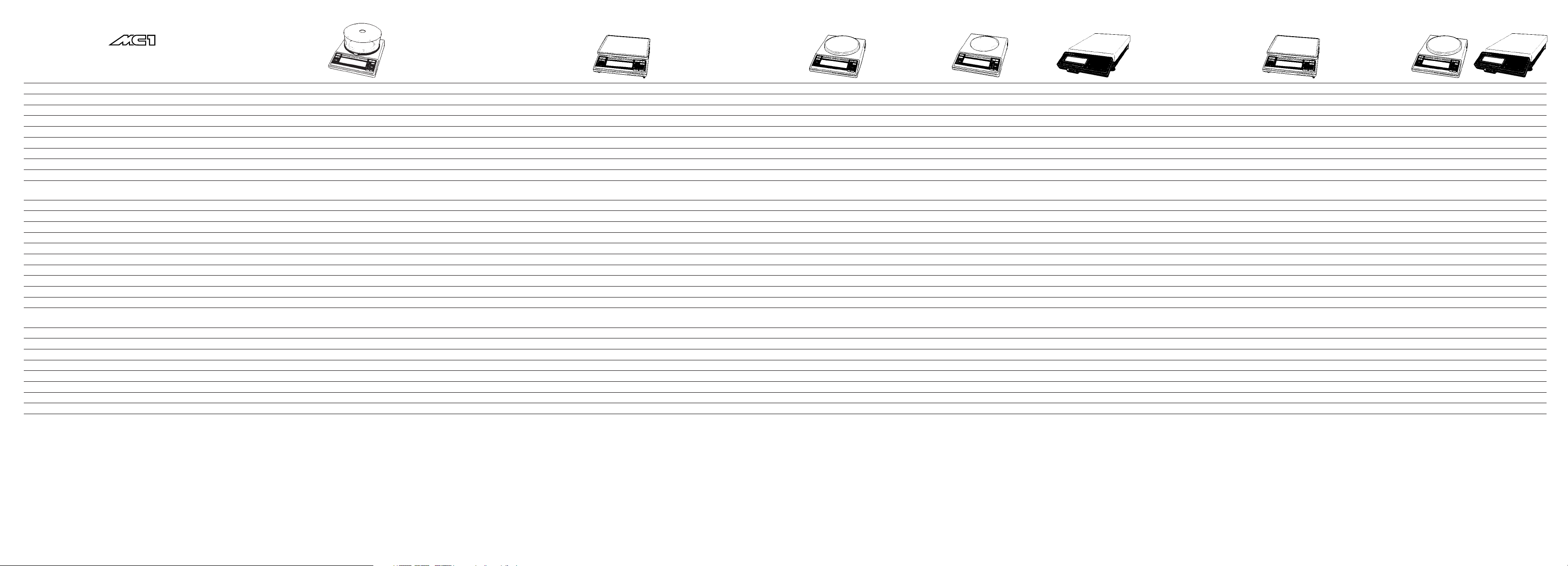
Specifications: Product Line1)
Model
Weighing range structure
Capacity/weighing range levels g
Readability g
Tare range (by subtraction) g
Reproducibility (standard deviation) g
Linearity g
Response time (average) s
Shortest response time in the IQ-Mode s
Adaptation to ambient conditions
and application requirements
Display update(dependsonthefilterlevelselected)
s
Sensitivity drift within 283–303 K /K
Ambient temperature range K
Pan size mm/in
Net weight, approx. kg/lb
AC power source/power requirements V~
Frequency Hz
Power consumption VA
Selectable weight units
Application programs
Automatic zero tracking function
(can be turned off by menu code)
Built-in interface
Standard features/equipment supplied
Dust cover
Draft shield
AC adapter
Hanger for below-balance weighing
Built-in, motorized calibration weight
LC 3201 D
DualRange
1,000/3,200
0.001/0.01
–3,200
≤±0.001/0.01
≤±0.002/0.01
▲▲
–––––––––––––––––––––––––––––––––––––––––––––––––––––––––––––––––––––––––––––––––––––––––––––––––––––––––––––––––––––––– ≤ 1.5 ––––––––––––––––––––––––––––––––––––––––––––––––––––––––––––––––––––––––––––––––––––––––––––––––––––––––––––––––––––––––
––––––––––––––––––––––––––––––––––––––––– 1 ––––––––––––––––––––––––––––––––––––––––
▲▲▲
–––––––––––––––––––––––––––––––––––––––––––––––––––––––––––––––––––––––––––––––––––––––––––––––––––––––––––––––––––––––––––––––––––––––––––––––––––––––––––– by selection of 1 of 4 optimized filter levels ––––––––––––––––––––––––––––––––––––––––––––––––––––––––––––––––––––––––––––––––––––––––––––––––––––––––––––––––––––––––––––––––––––––––––––––––––––––––––––
–––––––––––––––––––––––––––––––––––––––––––––––––––––––––––––––––––––––––––––––––––––––––––––––––––––––––––––––––––––––––––––––––––––––––––––––––––––––––––––––––––––––––– 0.1–0.4 ––––––––––––––––––––––––––––––––––––––––––––––––––––––––––––––––––––––––––––––––––––––––––––––––––––––––––––––––––––––––––––––––––––––––––––––––––––––––––––––––––––––––––
▲▲▲▲
––––––––––––––––––––––––––––––––––––––––––––––––––––––––––––––––––––––––––––––––––––––––––––––––––––––––––––––––––––––––––––––––––––––––––––––––––––––––––– 273–313 (0°C…+40°C; +32°F – +104 °F) –––––––––––––––––––––––––––––––––––––––––––––––––––––––––––––––––––––––––––––––––––––––––––––––––––––––––––––––––––––––––––––––––––––––––––––––––––––––––––
LC 1201S
SuperRange
1,200
0.001
–1,200
≤±0.001
≤±0.002
LC 621 S
SuperRange
620
0.001
–620
≤±0.001
≤±0.002
▲
▲
LC 621 P
PolyRange
120/240/620
0.001/0.002/0.005
–620
≤±0.001/0.001/0.003
≤±0.002/0.002/0.005
LC 221 S
SuperRange
220
0.001
–220
≤±0.001
≤±0.002
LC 6201 S
SuperRange
6,200
0.01
–6,200
≤±0.01
≤±0.02
▲
▲
––––––––––––––––––––––––––––––––––––––––––––––––––––––––––––––––––––––––––––––– 0.8 ––––––––––––––––––––––––––––––––––––––––––––––––––––––––––––––––––––––––––––––
▲▲
▲▲
LC 4801 P
PolyRange
800/1,600/3,000/4,800
0.01/0.02/0.05/0.1
–4,800
≤±0.01/0.02/0.05/0.1
≤±0.02/0.02/0.03/0.05
▲
▲
LC 4201 S
SuperRange
4,200
0.01
–4,200
≤±0.01
≤±0.02
LC 2201 S
SuperRange
2,200
0.01
–2,200
≤±0.005
≤±0.02
▲▲
▲▲
LC 2201 P
PolyRange
400/800/2,200
0.01/0.02/0.05
–2,200
≤±0.01/0.01/0.03
≤±0.02/0.02/0.05
LC 821
820
0.01
–820
≤±0.005
≤±0.01
▲
▲
LC 421
420
0.01
–420
≤±0.005
≤±0.01
▲
▲
LC 34000 P
PolyRange
8,000/16,000/34,000
0.1/0.2/0.5
–34,000
≤±0.1/0.2/0.5
≤±0.2/0.2/0.5
▲
▲
▲▲
LC 16000 S
SuperRange
16,000
0.1
–16,000
≤±0.1
≤±0.2
▲
▲
LC 12001S
SuperRange
12,000
0.1
–12,000
≤±0.1
≤±0.1
▲
▲▲
––––––––––––––––––––––––––––––––––––––––––––––––– ≤ 1 –––––––––––––––––––––––––––––––––––––––––––––––––
▲
–––––––––––––––––––––––––––––––––––––––––––––––– 0.7 ––––––––––––––––––––––––––––––––––––––––––––––––
▲
▲
––––––––––––––––––––––––––––––––––––– ≤±4 ·10
▲
▲
–––––––––––––––––––––––––– 235x180/9.3 x 7.1–––––––––––––––––––––––––––––––––––– 417x307/16.5 x12.1––––––––– 130 Ø /5.1Ø –––––––––––––––––––– 170 Ø /6.7 Ø ––––––––––––––––––––––––––––––––––––– 235 x180 /9.3 x7.1–––––––––––––––––––––––––––––––––––––––––––––––––––––– 130 Ø /5.1Ø ––––––––––––––––––––––––––––––––––– –
▲
▲
–––––––––––––––––––––––––––––––––– 4 ––––––––––––––––––––––––––––––––––––––––––––––––––– 15 ––––––––––––––––––––––––––––––––––––––––––––––– 3.6 –––––––––––––––––––––––––––––––––––––––––––––––––– 5.5 ––––––––––––––––––––––– 6.5 –––––––––––––––––––––––––––––– 5.5 ––––––––––––––––––––––––––––––––––––– 6.5 ––––––––––––– –––––– 15 ––––––
LC 12001P
PolyRange
3,000/6,000/12,000
0.1/0.2/0.5
–12,000
≤±0.1/0.1/0.2
≤±0.1/0.2/0.5
LC 6201
6,200
0.1
–6,200
≤±0.1
≤±0.1
LC 4201
4,200
0.1
–4,200
≤±0.1
≤±0.1
–6
–––––––––––––––––––––––––––––––––––––
LC 2201
2,200
0.1
–2,200
≤±0.05
≤±0.1
▲
▲
– 170 Ø/6.7 Ø –
▲
▲
––––– 3.6 –––––
LC 34
34,000
1
–34,000
≤±0.5
≤±1
▲
▲
–– ≤ ± 10·10
417x 307/16.5 x12.1
▲▲
▲▲
–6
–––– ≤± 2.5 ·10–6–––––––––––––––––––––––– ≤± 4 ·10–6–––––––––––––––––––––––––––––––––––––––––––––––––––––––––––––––––––––––––––––––––––––––––––––––––––––––– ≤ ± 2 ·10–6–––––––––––––––––––––––––––––––––––––––––––––––––––––––––––––––––––––––––––––––––––
––––––––––––––––––––––––––––––––––––––––––––––––––––––––––––––––––––––––––––––––––––––––––––––––––––––––––––––––––––––––––––––––––––––––––––––––––––––––––––––– via AC adapter 230 or 115, –20%...+15% –––––––––––––––––––––––––––––––––––––––––––––––––––––––––––––––––––––––––––––––––––––––––––––––––––––––––––––––––––––––––––––––––––––––––––––––––––––––––
▲▲▲▲▲▲
–––––––––––––––––––––––––––––––––––––––––––––––––––––––––––––––––––––––––––––––––––––––––––––––––––––––––––––––––––––––––––––––––––––––––––––––––––––––––––––––––––––––––– 48 – 60 ––––––––––––––––––––––––––––––––––––––––––––––––––––––––––––––––––––––––––––––––––––––––––––––––––––––––––––––––––––––––––––––––––––––––––––––––––––––––––––––––––––––––––
▲
▲
▲
▲
––––––––––––––––––––––––––––––––– max.:16; average: 8 –––––––––––––––––––––––––––––––––––––––––– max.:18; average:10 –––––––––––––––––––––––––––––––––––––––––––––––––––––––––––––––––––––––––––––––––––––––––––––––––––––––– max.:16; average: 8––––––––––––––––––––––––––––––––––––––––––––––––––––––––––––––––––––––––––––––––––––––––––––––– –– m:18; avg:10––
▲
▲
––––––––––––––––––––––––––––––––––––––––––––––––––––––––––––––––––––––––––––––––––––––––––––––––––––––––––––––––––––––––––––––––––––––––––––––––––––––––––– g, kg, ct, lb, oz, ozt, tlh, tls, tlt, gr, dwt and mg ––––––––––––––––––––––––––––––––––––––––––––––––––––––––––––––––––––––––––––––––––––––––––––––––––––––––––––––––––––––––––––––––––––––––––––––––––––––––––
–––––––––––––––––––––––––––––––––––––––––––––––––––––––––––––––––––––––––––––––––––––––––––––––––––––––––––––––––––– mass unit conversion by toggling; tare memory; net total; weighing in percent; over/under checkweighing (classification and filling); counting ––––––––––––––––––––––––––––––––––––––––––––––––––––––––––––––––––––––––––––––––––––––––––––––––––––––––––––––––––––
––––––––––––––––––––––––––––––––––––––––––––––––––––––––––––––––––––––––––––––––––––––––––––––––––––––––––––––––––––––––––––––––––––––––––––––––––––––––––––––––––––––– standard feature –––––––––––––––––––––––––––––––––––––––––––––––––––––––––––––––––––––––––––––––––––––––––––––––––––––––––––––––––––––––––––––––––––––––––––––––––––––––––––––––––––––––
––––––––––––––––––––––––––––––––––––––––––––––––––––––––––––––––––––––––––––––––––––––––––––––––––––––––––––––––– RS-232C-S/V24-V28; 7-bit; parity: even, mark, odd, space; transmission rate: 150…19,200 baud; 1 or 2 stop bits; software/hardware handshake ––––––––––––––––––––––––––––––––––––––––––––––––––––––––––––––––––––––––––––––––––––––––––––––––––––––––––––––––
x
x
x
x
x
x
x
x
x
x
x
x
x
x
x
x
x
x
x
x
x
x
x
x
x
x
x
x
x
x
x
x
x
x
x
x
x
x
x
x
x
x
x
x
xx
x
x
x
x
x
x
x
x
x
x
x
x
x
x
x
x
x
▲▲
▲▲▲
▲▲
–
▲
▲ ▲ ▲ ▲ ▲ ▲ ▲
1
) Balances of the MC1 Product Line cannot be upgraded to Master series balances but can be retrofitted with an IAC (Integrated Applications Computer) for complex applications.
6–8 6–9
Page 96

Specifications – Gold Series1)
Model GC 1201-G
Capacity/readability Grams 1,200 g/0.01 g
Tare range (by subtraction) g –1,200
Reproducibility (Standard deviation) g ≤ ± 0.005
Linearity g ≤ ± 0.02
Response time (average) s ≤1.5
Shortest response time in the IQ-Mode s 0.8
Adaptation to ambient conditions and application requirements by selection of 1of 4 optimized filter levels
Display update (depends on the filter level selected) s 0.1– 0.4
Sensitivity drift within 283…303 K /K ≤± 2 ·10
Ambient temperature range K 273…313 (0°C…+40°C; 32°F…104°F)
Pan size mm/in 130/5.1 Ø
Net weight, approx. kg 3.6
AC power source/power requirements V~ via AC adapter, 230 or115, +15% …–20%
Frequency Hz 48–60
Power consumption VA max.: 16; average: 8
Selectable weight units g, kg, ct, lb, oz, ozt, tlh, tls, tlt, gr, dwt and mg
Application programs mass unit conversion by toggling; weighing in percent; tare memory; net total, over/under checkweighing
Automatic zero tracking function (can be turned off by menu code) standard feature
Built-in interface RS-232C-S/V24-V28; 7-bit; parity: even, mark, odd, space;
Standard features/equipment supplied
Dust cover x
AC adapter x
Hanger for below-scale weighing x
Troy ounces 38.5 ozt/0.0005 ozt
Pennyweights 771 dwt/0.005 dwt
–6
(classification and filling); counting
transmission rate: 150…19,200 baud,1 or 2 stop bits, software/hardware handshake
1
) Cannot be upgraded to Master series balances but can be retrofitted with an IAC
(Integrated Applications Computer) for complex applications.
6–116–10
Page 97

Specifications: Master Series – Verified Balances
with An EC Type-Approval
Model AC 211S-0CEMS AC 211P-0CEMS AC 121 S-0CEMS
Pattern –––––––––––––––––––––––––––––––––––––– MC BA 100 ––––––––––––––––––––––––––––––––––––––
Accuracy class* –––––––––––––––––––––––––––––––––––––––––
▲
▲
–––––––––––––––––––––––––––––––––––––––––
k
Weighing range structure SuperRange PolyRange SuperRange
Max. capacity* g 210 60/120/210 120
Scale interval d* g 0.0001 0.0001/0.0002/0.0005 0.0001
Verification scale interval e* g –––––––––––––––––––––––––––––––––––––––– 0.001 ––––––––––––––––––––––––––––––––––––––––
Minimum capacity* g ––––––––––––––––––––––––––––––––––––––––– 0.01 –––––––––––––––––––––––––––––––––––––––––
▲
▲▲▲▲▲▲
Tare range (by subtraction) % –––––––––––––––––––––––––––––– up to 105 of maximum capacity ––––––––––––––––––––––––––––––
Range of use acc.to Directive No. 90/384/EEC* g 0.01–210 0.01–210 0.01–120
Response time (average) s ––––––––––––––––––––––––––––––––––––––––– ≤ 2.5 ––––––––––––––––––––––––––––––––––––––––
Adaptation to ambient conditions and application requirements –––––––––––––––––––––––––– by selection of 1 of 4 optimized filter levels –––––––––––––––––––––––––
Display update (depends on the filter level selected) s ––––––––––––––––––––––––––––––––––––––– 0.1– 0.4 –––––––––––––––––––––––––––––––––––––––
Range of use (temperature) °C/°F –––––––––––––––––––––––––––––– 0°C to +40°C/+32 – +104°F––––––––––––––––––––––––––––––
Pan size mm/in ––––––––––––––––––––––––––––––––––––– 90 Ø/3.5 Ø –––––––––––––––––––––––––––––––––––––
▲▲▲▲▲▲▲
Weighing chamber (WxDxH) mm/in –––––––––––––––––––––––––––––– 200x180 x260/8x 7.1x10.2 ––––––––––––––––––––––––––––––
Clearance above the weighing pan mm/in ––––––––––––––––––––––––––––––––––––––– 254/10 –––––––––––––––––––––––––––––––––––––––
Net weight, approx. kg/lb ––––––––––––––––––––––––––––––––––––––– 7.5/16.5–––––––––––––––––––––––––––––––––––––––
AC power source/power requirements V~ ––––––––––––––––––––––––– via AC adapter, 230 or 115, +15% …–20% –––––––––––––––––––––––––
Frequency Hz –––––––––––––––––––––––––––––––––––––––– 48– 60 ––––––––––––––––––––––––––––––––––––––––
Power consumption VA –––––––––––––––––––––––––––––––––– max.:16; average: 8 ––––––––––––––––––––––––––––––––––
Selectable weight units –––––––––––––––––––––––––––––––––––––––––– g ––––––––––––––––––––––––––––––––––––––––––
▲
Application programs formulation; statistics; real-time clock with timer function for time-controlled measurements/weighing;
▲▲
––––––––––––– tare memory; animal weighing/averaging; ID no. for identification of data; ––––––––––––
mass unit conversion by toggling; net total; weighing in percent; over/under checkweighing; counting
Automatic zero tracking function (can be turned off by menu code) –––––––––––––––––––––––––––––––––––– standard feature ––––––––––––––––––––––––––––––––––––
Built-in interface –––––––––––––––––––––––– RS-232C-S/V24-V28; 7-bit; parity: even, odd;
▲
––––––––
transmission rate: 150…19,200 baud; 1 or 2 stop bits; software/hardware handshake
––––––––
Standard features/equipment supplied
Dust cover x x x
Analytical draft shield chamber x x x
AC adapter x x x
“isoCAL” self-calibration function x x x
ISO/GLP-compliant record/printout x x x
Numeric keypad x x x
** EC Directive No. 90/384/EEC for Non-Automatic Weighing Instruments applicable
in the EC/EU member states
▲ ▲
▲ ▲
▲ ▲ ▲ ▲ ▲ ▲
▲ ▲ ▲ ▲ ▲ ▲
▲
▲ ▲
▲
6–136–12
Page 98

Specifications: Product Line1) – Verified Balances/Scales
with An EC Type-Approval
Model AC 211S-0CE AC 211 P-0CE AC 121S-0CE
Pattern/type designation –––––––––––––––––––––––––––––––––––––– MC BA 100 ––––––––––––––––––––––––––––––––––––––
Accuracy class* –––––––––––––––––––––––––––––––––––––––––
▲
▲
–––––––––––––––––––––––––––––––––––––––––
k
Weighing range structure SuperRange PolyRange SuperRange
Max. capacity* g 210 60/120/210 120
Scale interval d* g 0.0001 0.0001/0.0002/0.0005 0.0001
Verification scale interval e* g –––––––––––––––––––––––––––––––––––––––– 0.001 ––––––––––––––––––––––––––––––––––––––––
Minimum capacity* g ––––––––––––––––––––––––––––––––––––––––– 0.01 –––––––––––––––––––––––––––––––––––––––––
▲
▲▲▲▲▲▲
Tare range (by subtraction) % –––––––––––––––––––––––––––––– up to 105 of maximum capacity ––––––––––––––––––––––––––––––
Range of use acc.to Directive No. 90/384/EEC* g 0.01–210 0.01–210 0.01–120
Response time (average) s ––––––––––––––––––––––––––––––––––––––––– ≤ 2.5 ––––––––––––––––––––––––––––––––––––––––
Adaptation to ambient conditions and application requirements –––––––––––––––––––––––––– by selection of 1 of 4 optimized filter levels –––––––––––––––––––––––––
Display update (depends on the filter level selected) s ––––––––––––––––––––––––––––––––––––––– 0.1– 0.4 –––––––––––––––––––––––––––––––––––––––
Range of use (temperature) ––––––––––––––––––––––––––––––––––––– 15°C to +25°C –––––––––––––––––––––––––––––––––––––
Pan size mm/in ––––––––––––––––––––––––––––––––––––– 90 Ø/3.5 Ø –––––––––––––––––––––––––––––––––––––
▲▲▲▲▲▲▲
Weighing chamber (WxDxH) mm/in –––––––––––––––––––––––––––––– 200x180 x260/8x 7.1x10.2 ––––––––––––––––––––––––––––––
Clearance above the weighing pan mm/in ––––––––––––––––––––––––––––––––––––––– 254/10 –––––––––––––––––––––––––––––––––––––––
Net weight, approx. kg/lb ––––––––––––––––––––––––––––––––––––––– 7.5/16.5–––––––––––––––––––––––––––––––––––––––
AC power source/power requirements V~ ––––––––––––––––––––––––– via AC adapter, 230 or 115, +15% …–20% –––––––––––––––––––––––––
Frequency Hz –––––––––––––––––––––––––––––––––––––––– 48– 60 ––––––––––––––––––––––––––––––––––––––––
Power consumption VA –––––––––––––––––––––––––––––––––– max.:16; average: 8 ––––––––––––––––––––––––––––––––––
Selectable weight units –––––––––––––––––––––––––––––––––––––––––– g ––––––––––––––––––––––––––––––––––––––––––
Application programs
Automatic zero tracking function (can be turned off by menu code) –––––––––––––––––––––––––––––––––––– standard feature ––––––––––––––––––––––––––––––––––––
Built-in interface –––––––––––––––––––––––– RS-232C-S/V24-V28; 7-bit; parity: even, odd;
▲
▲
––––––––––––
▲
▲
––––––––
transmission rate: 150…19,200 baud; 1 or 2 stop bits; software/hardware handshake
mass unit conversion by toggling; tare memory; net total; weighing in percent;
over/under checkweighing (classification and filling); counting
–––––––––––
––––––––
Standard features/equipment supplied
Dust cover x x x
Analytical draft shield chamber x x x
AC adapter x x x
Built-in, motorized calibration weight x x x
** EC Directive No. 90/384/EEC for Non-Automatic Weighing Instruments applicable
in the EC/EU member states
▲ ▲
▲ ▲
▲ ▲ ▲ ▲ ▲ ▲
▲ ▲ ▲ ▲ ▲ ▲
▲
▲
▲ ▲
1
) Balances of the MC1 Product Line cannot be upgraded to Master series balances but can be retrofitted with an IAC
(Integrated Applications Computer) for complex applications.
6–156–14
Page 99

Specifications: Master Series – Verified Models with an EC Type-Approval
And Models Acceptable for Verification
Model
Pattern/type designation
Accuracy class*
Weighing range structure
Max. capacity* g
Scale interval d* g
Verification scale interval e* g
Minimum capacity* g
Tare range (by subtraction) %
Range of use acc. to Directive No. 90/384/EEC* g
Response time (average) s
Adaptation to ambient conditions
and application requirements
Display update (depends on the filter level selected) s
Range of use (temperature) °C/°F
Pan size mm
Net weight, approx. kg/lb
AC power source/power requirements V~
Frequency Hz
Power consumption VA
Selectable weight units
Application programs
Automatic zero tracking function
(can be turned off by menu code)
Built-in interface
Factory set state of delivery
LC 1201S-0CEMS
––––– MD BA 100 –––– –––––––––––––––––––––––––– MD BA 200 –––––––––––––––––––––––––– –––––––––––––––––––––––––– MA BA 200 –––––––––––––––––––––––––– –––––––––––––––––––––––– BA BA 200 ––––––––––––––––––––––––
▲ ▲
––––––––– k –––––––
SuperRange
1,200
0.001
0.01
0.1
▲
–––––––––––––––––––––––––––––––––––––––––––––––––––––––––––––––––––––––––––––––––––––––––––––––––––––––––––––––––––––––––––––––––––––––––––––––––––––––––––––––––– up to 105 of maximum capacity –––––––––––––––––––––––––––––––––––––––––––––––––––––––––––––––––––––––––––––––––––––––––––––––––––––––––––––––––––––––––––––––––––––––––––––––––––––––––––––––––
0.1–1,200
▲▲▲
LC 621 S-0CEMS
▲ ▲
▲▲
––––––––––––––––––––––––––––––––––––––––––––––––––––––––––––––––––––––––––––––––––––––––––––––––––––––––––––––––––––––––––––––––––––––––––––––––––––––––––––––––––– K –––––––––––––––––––––––––––––––––––––––––––––––––––––––––––––––––––––––––––––––––––––––––––––––––––––––––––––––––––––––––––––––––––––––––––––––––––––––––––––––––––
SuperRange
620
0.001
0.01
0.02
0.02–620
LC 621 P-0CEMS
PolyRange
120/240/620
0.001/0.002/0.005
0.01
0.02
0.02–620
LC 221 S-0CEMS
SuperRange
220
0.001
0.01
0.02
0.02–220
LC 6201 S-0CEMS
▲
▲
SuperRange
6,200
0.01
0.1
0.5
0.5–620
LC 4801 P-0CEMS
PolyRange
800/1,600/3,000/4,800
0.01/0.02/0.05/0.1
0.1
0.5
0.5–4,800
LC 4201 S-0CEMS
SuperRange
4,200
0.01
0.1
0.5
0.5–4,200
LC 2201 S-0CEMS
▲
▲
SuperRange
2,200
0.01
0.1
0.5
0.5–2,200
LC 2201 P-0CEMS
PolyRange
400/800/2,200
0.01/0.02/0.05
0.1
0.5
0.5–2,200
LC 821-0CEMS
820
0.01
0.1
0.5
0.5–820
LC 34000 P-0CEMS
LC 16000 S-0CEMS
–––––––––––––––– BB BA 200 ––––––––––––––– ––––––––––––––––––––––––––––––––– BA BA 200 ––––––––––––––––––––––––––––––––– ––––– BB BA 200 –––––
PolyRange
8,000/16,000/34,000
0.1/0.2/0.5
1
5
5–34,000
▲▲
––––––––––––––––––––––––––––––––––––––––––––––––––––––––––––––––––––– ≤ 1–––––––––––––––––––––––––––––––––––––––––––––––––––––––––––––––––––––––––––––––––––––––––––––––––––––––––––––––––––––––––––––––––––––––––––––––––––––––––––––––––––––––––– ≤ 1.5 –––––––––––––––––––––––––––––––––––––––––––––––––––––––––––––––––––––––––––––––––––––––––––––––––––––
SuperRange
16,000
0.1
1
5
5–16,000
LC 12001S-0CEMS
▲
▲
SuperRange
12,000
0.1
1
5
5–12,000
LC 12001P-0CEMS
PolyRange
3,000/6,000/12,000
0.1/0.2/0.5
1
5
5–12,000
LC 6201-0CEMS
6,200
0.1
1
5
5–6,200
LC 2201-0CEMS
2,200
0.1
0.1
5
5–2,200
LC 34-0CEMS
▲
▲
34,000
1
1
50
50–34,000
––––––––––––––––––––––––––––––––––––––––––––––––––––––––––––––––––––––––––––––––––––––––––––––––––––––––––––––––––––––––––––––––––––––––––––––––––––––––––––– by selection of1of 4 optimized filter levels –––––––––––––––––––––––––––––––––––––––––––––––––––––––––––––––––––––––––––––––––––––––––––––––––––––––––––––––––––––––––––––––––––––––––––––––––––––––––––––
––––––––––––––––––––––––––––––––––––––––––––––––––––––––––––––––––––––––––––––––––––––––––––––––––––––––––––––––––––––––––––––––––––––––––––––––––––––––––––––––––––––––––– 0.1– 0.4 ––––––––––––––––––––––––––––––––––––––––––––––––––––––––––––––––––––––––––––––––––––––––––––––––––––––––––––––––––––––––––––––––––––––––––––––––––––––––––––––––––––––––––
▲
––––––––––––––––––––––––––––––––––––––––––––––––––––––––––––––––––––––––––––––––––––––––––––––––––––––––––––––––––––––––––––––––––––––––––––––––––––––––––––––––––––– 0 – +40/+32 – +104 ––––––––––––––––––––––––––––––––––––––––––––––––––––––––––––––––––––––––––––––––––––––––––––––––––––––––––––––––––––––––––––––––––––––––––––––––––––––––––––––––––––
▲▲
▲▲▲
––––––––––––––––––––––––––––––––––––––––––––––––––––––––––––––––––––––––––––––––––––––––––––––––––––––––––––––––––––––––––––––––––––––––––––––––––––––––––––– via AC adapter, 230 or 115, +15%...20% –––––––––––––––––––––––––––––––––––––––––––––––––––––––––––––––––––––––––––––––––––––––––––––––––––––––––––––––––––––––––––––––––––––––––––––––––––––––––––––
▲
▲
▲▲
▲ ▲
––––––––––––––––––––––––––––––––––––––––––––––––––––––––––––––––––––––––––––––––––––––––––––––––––––––––––––––––––––––––––––––––––––––––––––––––––––––––––––––––––––––––––– 48 – 60 –––––––––––––––––––––––––––––––––––––––––––––––––––––––––––––––––––––––––––––––––––––––––––––––––––––––––––––––––––––––––––––––––––––––––––––––––––––––––––––––––––––––––––
––––––––––––––––––––––––––––––––––––––––––––––––––––––––––––––––––––––––––––––––––––––––––––––– max.: 16; average: 8 ––––––––––––––––––––––––––––––––––––––––––––––––––––––––––––––––––––––––––––––––––––––––––––––
▲▲▲▲▲
–––––––––––––––––––––––––––––––––––––––––––––––––––––––––––––––––––––––––––––––––––––––––––––––––––––––––––––––––––––––––––––––––––––––––––––––––––––––––––––––––––––––––––– g, kg ––––––––––––––––––––––––––––––––––––––––––––––––––––––––––––––––––––––––––––––––––––––––––––––––––––––––––––––––––––––––––––––––––––––––––––––––––––––––––––––––––––––––––––
▲
▲ ▲ ▲
▲
▲
––––––––––– max.: 18; average: 10 –––––––––––
▲
▲▲
▲
▲
––––––––––––––––––––––––––––– max.: 16; average: 8 –––––––––––––––––––––––––––––
▲
▲
▲
– 417x307/16.5 x12.1 ––––––––––––––––––––– 235 x180/9.3 x 7.1 ––––––––––––––––––– ––– 170 Ø/6.7 Ø ––––––––––––– 417x 307/16.5x12.1 ––––––––––––––––––––––––––––––––– Ø170/6.7 Ø –––––––––––––––––––––––––––––––––––––––––––––– 235x180/9.3 x 7.1 ––––––––––––––––––––––––––––––––––––––––––––––––––––––––––– 130 Ø/5.1 Ø –––––––––––––––––––––––––––––––––––
▲
––––––––– 15 ––––––––––––––––––––––––––––––––––––––––––––– 4.5 ––––––––––––––––––––––––––––––––––––––––––––––––––––––––15 ––––––––––––––––––––––––––––––––––––––––––––––– 4.5 –––––––––––––––––––––––––––––––––––––––––––––––––––––––––––––––––––––––––––––––––––––––––––––––––––– 6.5 ––––––––––––––––––––––––––––––––––––––––––––––––––––––––––––––––––––––––
▲
▲
–max.:18;average:10 –
–––––––––––––––––––––––––––––––––––––––––––––––––––––––– formulation; statistics; weighing in percent; real-time clock with timer function for time-controlled measurements/weighing; tare memory; animal weighing/averaging; ID no. for identification of data; mass unit conversion by toggling; tare memory; net total; over/under checkweighing; counting –––––––––––––––––––––––––––––––––––––––––––––––––––––––
–––––––––––––––––––––––––––––––––––––––––––––––––––––––––––––––––––––––––––––––––––––––––––––––––––––––––––––––––––––––––––––––––––––––––––––––––––––––––––––––––––––––– standard feature –––––––––––––––––––––––––––––––––––––––––––––––––––––––––––––––––––––––––––––––––––––––––––––––––––––––––––––––––––––––––––––––––––––––––––––––––––––––––––––––––––––––
––––––––––––––––––––––––––––––––––––––––––––––––––––––––––––––––––––––––––––––––––––––––––––––––––––––––––––––––––––––– RS-232C-S/V24-V28; 7-bit; parity: even, odd; transmission rate: 150...19,200 baud; 1 or 2 stop bits; software/hardware handshake ––––––––––––––––––––––––––––––––––––––––––––––––––––––––––––––––––––––––––––––––––––––––––––––––––––––––––––––––––––––
––––––––––––––––––––––––––––––––––––––––––––––––––––––––––––––––––––––––––––––––––––– verified for use as legal measuring instrument –––––––––––––––––––––––––––––––––––––––––––––––––––––––––––––––––––––––––––––––––––––
▲▲
▲ ▲
–––––––––– acceptable for verification –––––––––
▲
▲ ▲ ▲
–––––––––––––––––––– verified for use as legal measuring instrument –––––––––––––––––––
▲
▲ ▲
––
acceptable for verification
▲▲
▲▲ ▲ ▲ ▲
▲ ▲
▲ ▲ ▲
▲ ▲ ▲
▲
▲
––
Standard features/equipment supplied
Dust cover
Draft shield
AC adapter
“isoCAL” self-calibration function
ISO/GLP-compliant record/printout
Numeric keypad
x
x
x
x
x
x
x
x
x
x
x
x
x
x
x
x
x
x
*EC Directive No. 90/384/EEC for Non-Automatic Weighing Instruments applicable in the EC/EU member states
x
x
x
x
x
x
x
x
x
x
x
x
x
x
x
x
x
x
x
x
x
x
x
x
x
x
x
x
x
x
x
x
x
x
x
x
x
x
x
x
x
x
x
x
x
x
x
x
x
x
x
x
x
x
x
x
x
x
x
x
x
x
x
x
x
x
x
x
x
x
x
6–16 6–17
Page 100

Specifications: Product Line1) – Verified Models
with an EC Type-Approval And Models Acceptable
for Verification
Model
Pattern/type designation
Accuracy class*
Weighing range structure
Max. capacity* g
Scale interval d* g
Verification scale interval e* g
Minimum capacity* g
Tare range (by subtraction) %
Range of use acc. to Directive No. 90/384/EEC* g
Response time (average) s
Adaptation to ambient conditions
and application requirements
Display update (depends on the filter level selected) s
Range of use (temperature) °C
Pan size mm
Net weight, approx. kg/lb
AC power source/power requirements V~
Frequency Hz
Power consumption VA
Selectable weight units
Application programs
Automatic zero tracking function
(can be turned off by menu code)
Built-in interface
Factory set state of delivery
LC 1201S-0CE
–––– MD BA 100 –––– –––––––––––––––––––––––––– MD BA 200 –––––––––––––––––––––––––– –––––––––––––––––––––––––– MA BA 200 –––––––––––––––––––––––––– –––––––––––––––––––––––– BA BA 200 ––––––––––––––––––––––––
▲ ▲
––––––––
k ––––––––
SuperRange
1,200
0.001
0.01
0.1
▲
–––––––––––––––––––––––––––––––––––––––––––––––––––––––––––––––––––––––––––––––––––––––––––––––––––––––––––––––––––––––––––––––––––––––––––––––––––––––––––––––––– up to 105 of maximum capacity –––––––––––––––––––––––––––––––––––––––––––––––––––––––––––––––––––––––––––––––––––––––––––––––––––––––––––––––––––––––––––––––––––––––––––––––––––––––––––––––––
0.1–1,200
▲▲▲
––––––––––––––––––––––––––––––––––––––––––––––––––––––––––––––––––––––––––––––––––––––––––––––––––––––––––––––––––––––––––––––––––––––––––––––––––––––––––––– by selection of 1 of 4 optimized filter levels –––––––––––––––––––––––––––––––––––––––––––––––––––––––––––––––––––––––––––––––––––––––––––––––––––––––––––––––––––––––––––––––––––––––––––––––––––––––––––––
––––––––––––––––––––––––––––––––––––––––––––––––––––––––––––––––––––––––––––––––––––––––––––––––––––––––––––––––––––––––––––––––––––––––––––––––––––––––––––––––––––––––––– 0.1– 0.4 ––––––––––––––––––––––––––––––––––––––––––––––––––––––––––––––––––––––––––––––––––––––––––––––––––––––––––––––––––––––––––––––––––––––––––––––––––––––––––––––––––––––––––
▲
––––+18 to +252) ––––
▲▲
▲▲▲
––––––––––––––––––––––––––––––––––––––––––––––––––––––––––––––––––––––––––––––––––––––––––––––––––––––––––––––––––––––––––––––––––––––––––––––––––––––––––––– via AC adapter, 230 or 115, +15%...20% –––––––––––––––––––––––––––––––––––––––––––––––––––––––––––––––––––––––––––––––––––––––––––––––––––––––––––––––––––––––––––––––––––––––––––––––––––––––––––––
––––––––––––––––––––––––––––––––––––––––––––––––––––––––––––––––––––––––––––––––––––––––––––––––––––––––––––––––––––––––––––––––––––––––––––––––––––––––––––––––––––––––––– 48 – 60 –––––––––––––––––––––––––––––––––––––––––––––––––––––––––––––––––––––––––––––––––––––––––––––––––––––––––––––––––––––––––––––––––––––––––––––––––––––––––––––––––––––––––––
––––––––––––––––––––––––––––––––––––––––––––––––––––––––––––––––––––––––––––––––––––––––––––––– max.: 16; average: 8 ––––––––––––––––––––––––––––––––––––––––––––––––––––––––––––––––––––––––––––––––––––––––––––––
▲▲▲▲▲
–––––––––––––––––––––––––––––––––––––––––––––––––––––––––––––––––––––––––––––––––––––––––––––––––––––––––––––––––––––––––––––––––––––––––––––––––––––––––––––––––––––––––––– g, kg ––––––––––––––––––––––––––––––––––––––––––––––––––––––––––––––––––––––––––––––––––––––––––––––––––––––––––––––––––––––––––––––––––––––––––––––––––––––––––––––––––––––––––––
––––––––––––––––––––––––––––––––––––––––––––––––––––––––––––––––––––––––––––––––––––––––––––––––––––––––––––––––––––– mass unit conversion by toggling; tare memory; net total; weighing in percent; over/under checkweighing (classification and filling); counting –––––––––––––––––––––––––––––––––––––––––––––––––––––––––––––––––––––––––––––––––––––––––––––––––––––––––––––––––––––
–––––––––––––––––––––––––––––––––––––––––––––––––––––––––––––––––––––––––––––––––––––––––––––––––––––––––––––––––––––––––––––––––––––––––––––––––––––––––––––––––––––––– standard feature –––––––––––––––––––––––––––––––––––––––––––––––––––––––––––––––––––––––––––––––––––––––––––––––––––––––––––––––––––––––––––––––––––––––––––––––––––––––––––––––––––––––
––––––––––––––––––––––––––––––––––––––––––––––––––––––––––––––––––––––––––––––––––––––––––––––––––––––––––––––––––––––– RS-232C-S/V24-V28; 7-bit; parity: even, odd; transmission rate: 150...19,200 baud, 1 or 2 stop bits; software/hardware handshake ––––––––––––––––––––––––––––––––––––––––––––––––––––––––––––––––––––––––––––––––––––––––––––––––––––––––––––––––––––––
–––––––––––––––––––––––––––––––––––––––––––––––––––––––––––––––––––––––––––––––––––––– verified for use as legal measuring instrument –––––––––––––––––––––––––––––––––––––––––––––––––––––––––––––––––––––––––––––––––––––
LC 621 S-0CE
▲ ▲
▲▲
––––––––––––––––––––––––––––––––––––––––––––––––––––––––––––––––––––––––––––––––––––––––––––––––––––––––––––––––––––––––––––––––––––––––––––––––––––––––––––––––––– K –––––––––––––––––––––––––––––––––––––––––––––––––––––––––––––––––––––––––––––––––––––––––––––––––––––––––––––––––––––––––––––––––––––––––––––––––––––––––––––––––––
SuperRange
620
0.001
0.01
0.02
0.02–620
▲
▲
––––––––––––––––––––––––––––––––––––––––––––––––––––––––––––––––––––––––––––––––––––––––––––––––––––––––––––––––––––––––––––––––––––––––––––––––––––––––– +10 – +30 (+50°F...+86°F) –––––––––––––––––––––––––––––––––––––––––––––––––––––––––––––––––––––––––––––––––––––––––––––––––––––––––––––––––––––––––––––––––––––––––––––––––––––––
LC 621 P-0CE
PolyRange
120/240/620
0.001/0.002/0.005
0.01
0.02
0.02–620
LC 221 S-0CE
SuperRange
220
0.001
0.01
0.02
0.02–220
LC 6201 S-0CE
▲
▲
SuperRange
6,200
0.01
0.1
0.5
0.5–6,200
▲
▲
LC 4801 P-0CE
PolyRange
800/1,600/3,000/4,800
0.01/0.02/0.05/0.1
0.1
0.5
0.5–4,800
LC 4201 S-0CE
SuperRange
4,200
0.01
0.1
0.5
0.5–4,200
LC 2201 S-0CE
▲
▲
SuperRange
2,200
0.01
0.1
0.5
0.5–2,200
▲▲
▲ ▲
LC 2201 P-0CE
PolyRange
400/800/2,200
0.01/0.02/0.05
0.1
0.5
0.5–2,200
LC 821-0CE
820
0.01
0.1
0.5
0.5–820
LC 34000 P-0CE
LC 16000 S-0CE
–––––––––––––––– BB BA 200 ––––––––––––––– ––––––––––––––––––––––––––––––––– BA BA 200 ––––––––––––––––––––––––––––––––– ––––– BB BA 200 –––––
PolyRange
8,000/16,000/34,000
0.1/0.2/0.5
1
5
5–34,000
▲▲
––––––––––––––––––––––––––––––––––––––––––––––––––––––––––––––––––––– ≤ 1–––––––––––––––––––––––––––––––––––––––––––––––––––––––––––––––––––––––––––––––––––––––––––––––––––––––––––––––––––––––––––––––––––––––––––––––––––––––––––––––––––––––––– ≤ 1.5 –––––––––––––––––––––––––––––––––––––––––––––––––––––––––––––––––––––––––––––––––––––––––––––––––––––
▲
▲ ▲ ▲
▲
▲
––––––––––– max.: 18; average: 10 –––––––––––
▲▲
▲ ▲
–––––––––– acceptable for verification –––––––––
SuperRange
16,000
0.1
1
5
5–16,000
LC 12001S-0CE
▲
▲
SuperRange
12,000
0.1
1
5
5–12,000
▲▲
▲
▲
––––––––––––––––––––––––––––– max.: 16; average: 8 –––––––––––––––––––––––––––––
▲
▲ ▲ ▲
–––––––––––––––––––– verified for use as legal measuring instrument ––––––––––––––––––––
LC 12001P-0CE
PolyRange
3,000/6,000/12,000
0.1/0.2/0.5
1
5
5–12,000
LC 6201-0CE
6,200
0.1
1
5
5–6,200
LC 2201-0CE
2,200
0.1
0.1
5
5–2,200
▲
▲
LC 34-0CE
▲
▲
34,000
1
1
50
50–34,000
▲
▲
– 417x307/16.5x12.1 –––––––––––––––––––– 235 x180/9.3 x7.1 ––––––––––––––––––– ––– 170 Ø/6.7 Ø ––––––––––––– 417x 307/16.5 x12.1 ––––––––––––––––––––––––––––––––– 170 Ø/6.7 Ø –––––––––––––––––––––––––––––––––––––––––––––– 235 x180/9.3x 7.1––––––––––––––––––––––––––––––––––––––––––––––––––––––––––– 130 Ø/5.1 Ø –––––––––––––––––––––––––––––––––––
▲
––––––––– 15 –––––––––––––––––––––––––––––––––––––––––––––– 4.5 ––––––––––––––––––––––––––––––––––––––––––––––––––––––––15 ––––––––––––––––––––––––––––––––––––––––––––––– 4.5 –––––––––––––––––––––––––––––––––––––––––––––––––––––––––––––––––––––––––––––––––––––––––––––––––––– 6.5 ––––––––––––––––––––––––––––––––––––––––––––––––––––––––––––––––––––––––
▲
▲
–– max.: 18; avg.: 10 ––
▲
▲ ▲
––
acceptable for verification
▲▲ ▲ ▲ ▲
▲ ▲
▲ ▲ ▲
▲ ▲ ▲ ▲▲▲
▲
––
Standard features/equipment supplied
Dust cover
Draft shield
AC adapter
Built-in, motorized calibration weight
x
x
x
x
x
x
x
x
x
x
x
x
x
x
x
x
x
x
x
x
*EC Directive No. 90/384/EEC for Non-Automatic Weighing Instruments applicable in the EC/EU member states
1
) Balances of the MC1 Product Line cannot be upgraded to Master series balances but can be retrofitted with an IAC (Integrated Applications Computer) for complex applications.
2
) 5°C within the range of +18 to +25°C
x
x
x
x
x
x
x
x
x
x
x
x
x
x
x
x
x
x
x
x
x
x
x
x
x
x
x
x
x
x
x
x
x
x
x
6–18 6–19
 Loading...