


IW2P1x-6ED-L,IW2P1x-15ED-L,IW2P1x-30ED-L,IW2P1x-150 series,IW2P1x-300GF-L,IW2P1x-60ED-L,IW2P1x-60FE-L
Sartorius IW2P1x-6ED-L,IW2P1x-15ED-L,IW2P1x-30ED-L,IW2P1x-150 series,IW2P1x-300GF-L,IW2P1x-60ED-L,IW2P1x-60FE-L Operating Instructions Manual
Operating Instructions | Betriebsanleitung | Mode d’emploi |
Istruzioni per l’uso | Manual de instrucciones
Sartorius Miras 2
IW Models | IW Modelle | Modèles IW | Modelli IW | Modelos IW
98648-018-73

2
Miras 2
English page 3
In cases involving questions of
interpretation, the German-language
version shall prevail.
Deutsch Seite 35
Im Auslegungsfall ist die
deutsche Sprache maßgeblich.
Français page 67
En cas de questions concernant
l’interprétation, la version
en langue allemande fera autorité.
Italiano pagina 99
In caso di interpretazione dubbia,
fa testo la versione in lingua tedesca.
Español página 131
En caso de interpretación,
la versión en lengua alemana
será determinante.
2
Miras 2
3
Contents
Description Page
Safety Precautions 4
Getting Started 7
General View of the Equipment 8
Setting Up the Scale 9
Operating Design 12
Descriptions of the Keys 15
Configuration (Setup Menu) 16
Application Programs 18
Counting 18
Check Weighing 19
Toggling between Weight Units 20
Calibration/Span Adjustment 21
SBI Interface Protocol Descriptions 23
RS-232 Interface Diagram 26
Print Formats 27
Error Codes 31
Care & Maintenance 32
Specifications 33
Accessories (Options) 33
C Marking 34
33
Contents
Contents
Description Page
Safety Precautions . . . . . . . . . . . . . . . . . . . . . . . 4
Getting Started . . . . . . . . . . . . . . . . . . . . . . . . . 7
General View of the Equipment . . . . . . . . . . . . . 8
Setting Up the Scale . . . . . . . . . . . . . . . . . . . . . 9
Operating Design . . . . . . . . . . . . . . . . . . . . . . . . 12
Descriptions of the Keys. . . . . . . . . . . . . . . . . . . 15
Configuration (Setup Menu) . . . . . . . . . . . . . . . 16
Application Programs. . . . . . . . . . . . . . . . . . . . . 18
Counting . . . . . . . . . . . . . . . . . . . . . . . . . . . . . . 18
Check Weighing . . . . . . . . . . . . . . . . . . . . . . . . . 19
Toggling between Weight Units. . . . . . . . . . . . . . 20
Calibration/Span Adjustment . . . . . . . . . . . . . . . 21
SBI Interface Protocol Descriptions . . . . . . . . . . 23
RS-232 Interface Diagram. . . . . . . . . . . . . . . . . 26
Print Formats . . . . . . . . . . . . . . . . . . . . . . . . . . . 27
Error Codes . . . . . . . . . . . . . . . . . . . . . . . . . . . . 31
Care & Maintenance . . . . . . . . . . . . . . . . . . . . . 32
Specifications. . . . . . . . . . . . . . . . . . . . . . . . . . . 33
Accessories (Options) . . . . . . . . . . . . . . . . . . . . . 33
C Marking . . . . . . . . . . . . . . . . . . . . . . . . . . . . 34
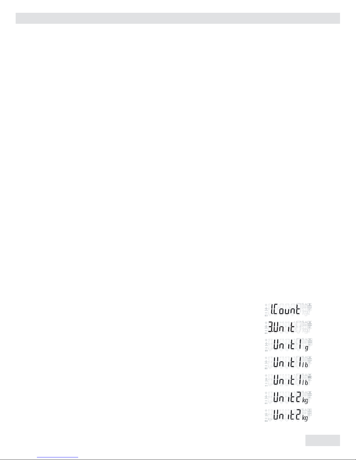
Select Weight Units
Step Key (or instruction) Display
Select application setup (Fn/Up) > 2 sec
Select “Toggling Weight Units” (Fn/Up) repeatedly
Confirm selection (Print/Enter)
Select weight unit 1 (Fn/Up)
Confirm weight unit 1 (Print/Enter)
Select weight unit 2 (Fn/Up)
Confirm weight unit 2 (Print/Enter)
4
Miras 2
Safety Precautions
4
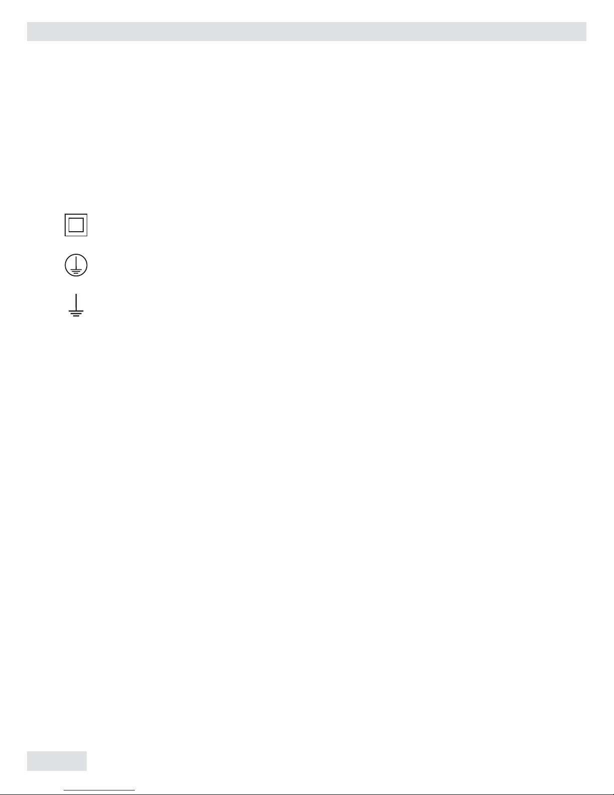
Explanation of Symbols:
! Caution, risk of danger:
Read the accompanying text carefully.
The instrument is double-insulated.
Protective conductor terminal
Earth ground terminal
Safety tips, electrical protection class
! This instrument was built and tested in accordance with the safety regulations
for measuring and control instrumentation for protection class I (protective earth
connection) according to IEC 1010/ EN61010-1 or VDE 0411. The instrument was
delivered in safe condition. To maintain this condition and to ensure safe operation,
the operator must follow the instructions and warnings given in this documentation
Protective earth
! The connecting cable of the unit complies with the regulations in accordance with
VDE 0411 or EN61010. The mains plug must contain a protective earth conductor,
which must not be interrupted inside or outside this instrument (e.g. by using an
extension cable without protective earth). Before commissioning, acceptance of the
installation by a technically competent expert is required.
Measurement category
! This instrument is designed for measurement
category I, with a maximum of 8.5 V. To ensure safe operation do not use this
instrument for measurements within the measurement categories II, III or IV.

Miras 2
5
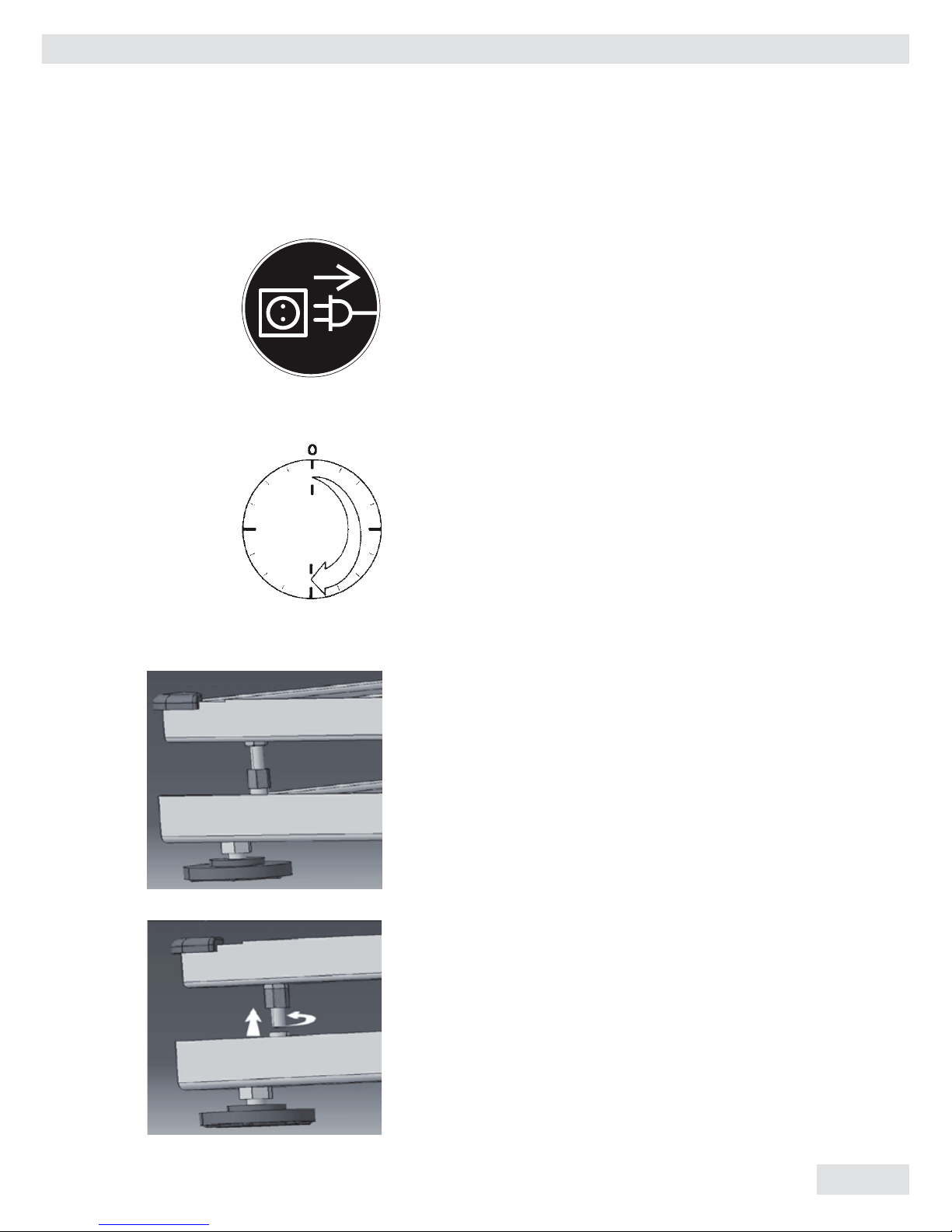
! Opening the instrument
CAUTION: DANGER TO LIFE!
– Working on the instrument when it is
switched on can be dangerous to life.
Disconnect the instrument from the
supply voltage! When removing covers
of parts by means of tools, live parts or
terminals may be exposed. Capacitors in
the unit may still be charged even after
disconnecting the unit from all voltage
sources.
– As the unit has no power switch, to
completely remove AC power from the
unit, disconnect the AC power cable
from the mains socket.
– Do not expose the scale unnecessarily to
aggressive chemical vapors or to
extreme temperatures,
moisture, shocks, or vibration.
– Avoid exposing the scale to static elec-
tricity; be sure to connect the equipotential bonding conductor to the junction box.
Repair and maintenance
– Repairs are subject to checking and can
be carried out only at Sartorius. In case
of defect or functional trouble, please
contact your local Sartorius dealer for
repair. When returning the instrument
for repair, an exact and complete fault
description must be supplied.
Only a trained technician aware of the
hazards involved may carry out maintenance work, during which the relevant
precautions must be taken.
Important note:
– Make sure that the construction of the
instrument is not altered to the detriment of safety. In particular, leakage
paths, air gaps (of live parts) and insu-
lating layers must not be reduced.
The manufacturer cannot be held
responsible for personal injury or damage caused by an instrument repaired
incorrectly by user or installer.
– Only authorized service technicians who
have been trained by Sartorius and who
follow Sartorius’s standard operating
procedures for maintenance and repair
may open the scale. If you see any indication that the scale cannot be operated
safely (for example, because of equipment damage), turn off the scale and
lock it in a secure place so that it cannot be used for the time being.
– If you use suction lifting equipment to
lift the load plate, always wear gloves,
hard-toed safety boots and protective
clothing. Warning: This procedure can
cause personal injury! Only reliable
personnel who are qualified to perform
such work are allowed to use suction
lifting equipment.
– Always make sure the scale is discon-
nected from AC power before performing any installation,
cleaning, maintenance or repair work.
– Check the pin assignment if you use
cables purchased from a different manufacturer. Before connecting such a
cable to Sartorius equipment, check the
pin assignment on the corresponding
wiring diagram or chart and disconnect
any wires that are assigned differently
from those specified by Sartorius.
The operator shall be solely responsible
for any damage or injuries that may
occur when using cables not supplied
by Sartorius.
5

6
Miras 2
! Note:
– Do not use this equipment in hazardous areas.
– Make sure the voltage rating printed on the
power supply is identical to your local line
voltage.
– Use only commercially available batteries
(rechargeable or dry-cell battery). If you use
a rechargeable battery, use only 12 V 2.3AH.
– The scale is energized at all times unless you
disconnect the AC power and the battery.
– Exposure to excessive electromagnetic interfer-
ence can cause the readout value to change.
Once the disturbance has ceased, the instrument
can be used again in accordance with its intended purpose.
6

Miras 2
7
Getting Started
Storage and Shipping Conditions
Do not expose the scale to shocks,
vibrations, moisture or extreme temperatures.
Unpacking the Scale
After unpacking the scale, check it
immediately for any visible damage as
a result of rough handling during shipment.
Note:
– The display and control unit is attached
to the weighing platform via a cable.
– If you see any sign of damage, proceed
as directed in the chapter entitled “Care
and Maintenance,” under the section on
“Safety Inspection.”
– Save the box and all parts of the
packaging until you have successfully
installed your scale. Only the original
packaging provides the best protection
for shipment. Before packing your scale,
unplug all connected cables to prevent
damage.
Equipment Supplied
The equipment supplied includes the
components listed below:
– Scale with attached display and control
unit
– Load pan
– Installation and operating instructions
Installation Instructions
The Sartorius Miras scales are designed
to provide reliable weighing results
under normal ambient conditions. When
choosing a location to set up your scale,
observe the following so that you will
be able to work with added speed and
accuracy:
– Set up the scale on a stable, even sur-
face
– Avoid placing the scale in close proxim-
ity to a heater or otherwise exposing the
scale to heat or direct sunlight
– Protect the scale from drafts that come
from open windows or doors
– Avoid exposing the scale to extreme
vibrations during weighing
– Protect the scale from aggressive
chemical vapors
– Do not expose the scale to extreme
moisture over long periods
– Remove transport locking: see page 9
Conditioning the Scale
Moisture in the air can condense on
the surfaces of a cold scale whenever it
is brought into a substantially warmer
place. If you transfer the scale to a
warmer area, make sure to condition it
for about 2 hours at room temperature,
leaving it unplugged from AC power.
Afterwards, keep the scale continuously
connected to AC power.
77
8
Miras 2
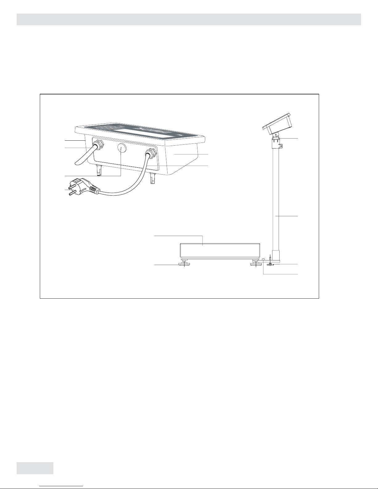
General View of the Equipment
1 Housing
2 Power cable
3 Display and control unit retainer
4 Display and control unit column
5 Column support foot
6 Level indicator (option)
7 Leveling feet
8 Stainless steel weighing pan
9 Power plug
10 Cable gland cover
(for optional RS-232 port outlet)
11 Load cell cable gland
12 Manufacturer’s ID tag
8
1
2
3
4
5
6
7
8
09
10
11
12
Miras 2
9
Setting Up the Scale
Connecting Electronic Peripheral Devices
§ Make absolutely sure to unplug the scale from AC
power or switch off (activate battery mode) before
you connect or disconnect a peripheral device (printer or PC) to or from the interface port.
Warm-up Time
To deliver exact results, the scale must warm up for
at least 30 minutes after
initial connection to AC power. Only after this time
will the scale have reached the required operating
temperature.
Transport Lock
– Under the metal frame structure there are four
safety overload protection pins (Note: not on all
platform models).
Before using the scale, rotate the nut (upwards) until
tight.
Place the load plate on the scale
9
10
Miras 2
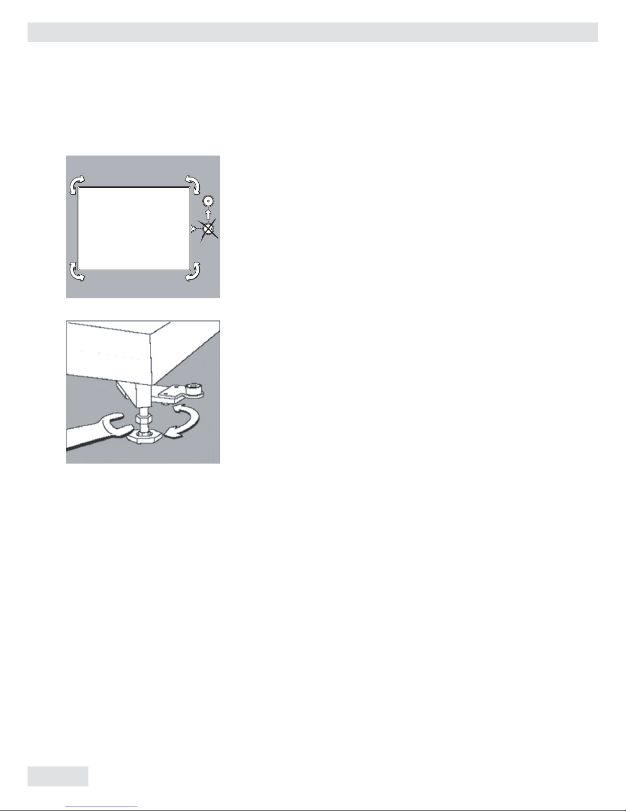
Leveling the Scale
– Remove the load plate
– Using the 4 foot screws, level the scale so that the
air bubble is centered within the level indicator
– Check to ensure that all leveling feet rest securely on
the work surface
10
Miras 2
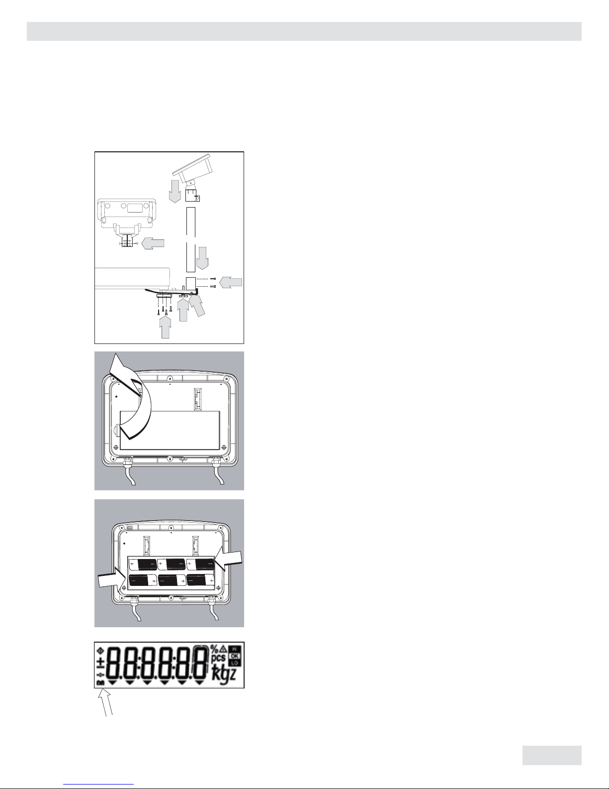
11
Assembly Procedure
1. Affix the column bracket with 4 screws
2. Install the column support leveling foot
3. Push the load cell cable into the column
4. Insert the column into the bracket holder
5. Affix the column with 2 screws
6. Insert the display and control unit retainer into the
column
7. Tighten the screw on the display and control unit
bracket
Battery-Powered Operation
To activate battery operation:
– Open the battery cover at the back of the Indicator.
– Insert 1.5 V size D dry-cell batteries (not included)
into the battery compartment.
– The battery symbol is displayed when the unit is
operating on battery power.
– If the battery symbol flashes, the battery power is
weak.
Replace the batteries (if using dry-cell batteries).
11
4
5
7
6
1
2
3

12
Miras 2
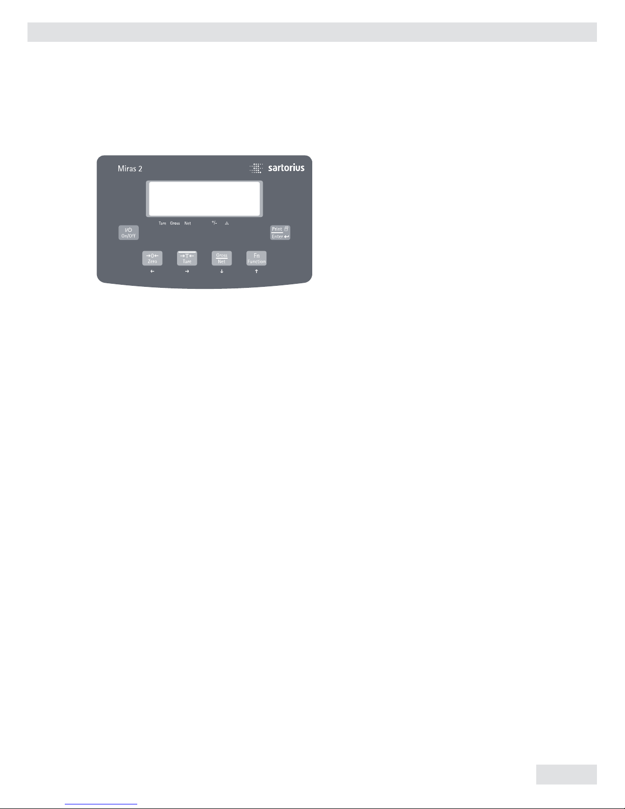
Operating Design
The scales in the Miras series consist
of a weighing cell and a display and
control unit. In addition to the choice
of power supply or rechargeable maintenance-free lead acid battery or dry
battery.
The display and control unit is affixed
to the weighing platform. Operation of
the Miras scale is simple and uniform.
The Miras models include the features
like gross/net toggling, counting,
checkweighing & unit toggling.
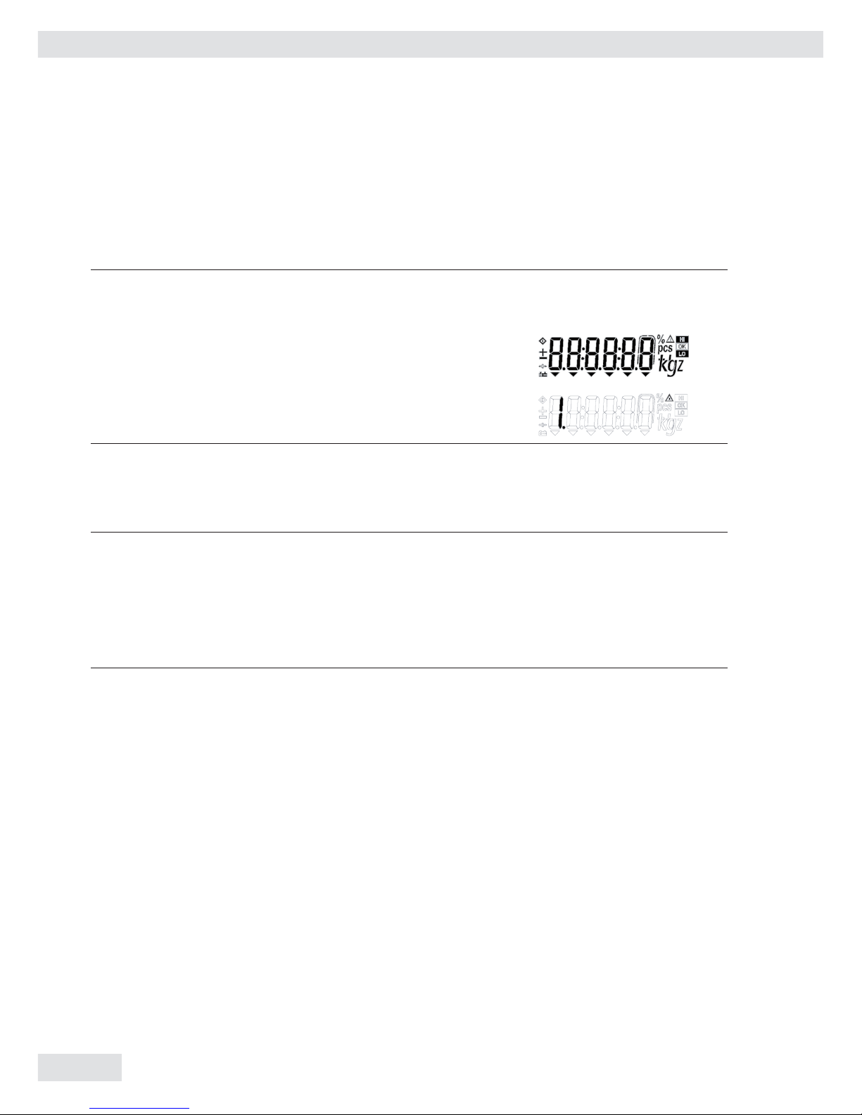
Display
The display is divided into sections:
Busy Symbol, Plus/Minus Sign
If the symbol displayed here is a diamond b, this indicates that the scale
is performing a function (busy symbol).
A plus or minus sign (+ or –) refers to
the value displayed.
Measured Value
Shows the measured value
Basic Unit and Additional Information
– When the scale has stabilized, the
weight unit is displayed here (g, kg,..).
– The arrows below the weight indications
shows the weighing mode (gross/net)
and the application mode (counting,
checkweighing, or unit toggling) enabled, if any.
– The
!
symbol indicates the unit is
not in weighing mode (e.g.: calibration
mode, configuration mode, error mode)
12
Miras 2
13
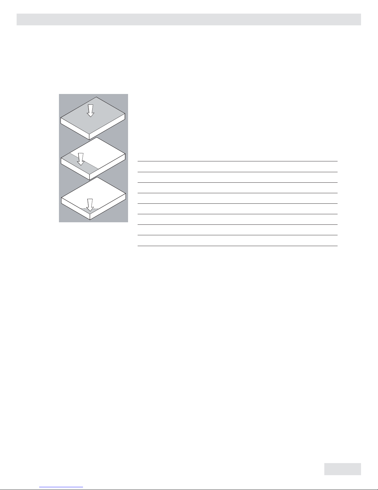
Operating Limits
Never exceed the maximum capacity of the scale.
The maximum loading capacities of the scales in this series are
listed in the table below and depend on the position of the load
on platform:
Model Width Length Center* Side Corner
(mm) (mm) kg kg kg
IW2P1.–6ED… 300 4000 50 35 20
IW2P1.–15ED… 300 400 130 85 45
IW2P1.–30ED… 300 400 500 400 200
IW2P1.–60ED… 300 400 600 400 200
IW2P1.–60FE… 400 500 600 400 200
IW2P1.–150FE… 400 500 600 400 200
IW2P1U–150GF… 500 650 600 400 200
IW2P1.–300GF… 500 650 600 400 200
13

14
Miras 2
Scale connected to AC power:
On/Off Switch:
On: Scale is operational and display
shows function or mode that is in use
Off: Depends on menu setting (“4.
Standby option.”), scale is completely
off (no display and no internal circuitry)
or in standby (no display and internal
circuitry working).
Back Light:
Depends on menu setting (“2. Backlight”). Backlight is on/off.
Auto Power Off:
Not active.
Scale running on battery power:
On/Off Switch:
On: Scale is operational and the display
shows the function or mode that is in
use
Off: Completely off (no display and no
internal circuitry working)
Back Light:
Depends on menu setting (“2. Backlight”). Backlight is on/off. Backlight
goes off after 15 seconds if no operation is done (no key pressed/no weighing). Backlight comes back on whenever
a key (except on/off) is pressed or when
a load is placed on the scale.
Auto Power Off:
Depends on menu setting (“3. Auto
power off”); system power shuts down.
Time limit options for auto power in
setup menu are 5, 10 or 15 minutes,
or can be disabled.
14
Power Management Option
Miras 2
15
15
Descriptions of the Keys
1) On/Off
“On/off” function will depend on
different power supply conditions.
Use the setup menu for backlight
control and for auto power off.
In Main Mode
§ Off-Mode:
If standby active: Scale is in standby
mode, but there is no display visible
other than mode symbol (no backlight,
no display, no symbols)
If standby not active:
Scale is completely off
§ On-Mode:
Scale is in operation and the display
shows the function that is in use.
In this mode, auto power off function
is invalid.
In Battery Mode
§ Off-Mode: Scale is completely off.
§ On-Mode: Scale is in operation and the
display shows the function that is in use.
Backlight works based on setup menu
In this mode, auto power off function
is valid. After 5, 10 or 15 minutes, the
system shuts off when not in use in
accordance with the setup menu setting.
2) Zero/Arrow-Left (Zero/Left)
Weighing mode: Set scale to zero
Parameter mode: Shift position of digit
to the left
3) Tare/Arrow-Right (Tare/Right)
Weighing mode: Tare the scale
Parameter mode: Shift position of digit
to the right
4) Gross-Net/Arrow-Down (G/N/Down)
Weighing mode: Toggle weight unit
gross/net
Counting mode: Toggle weight unit
gross, net and pcs
Function mode: To scroll down menu
selection
Parameter mode: Reduce digit value by 1
5) Function/Arrow-Up (Fn/Up)
Weighing mode: Switch the scale from
normal weighing mode to application
setup mode
Function mode: Scroll up in menu
selection
Parameter mode:
Increase digit value by 1
6) Print/Enter (Print/Enter)
Weighing mode: Print key
Function mode: Scroll level up in menu
mode/confirm selected menu.
16
Miras 2
16
Configuration (Setup Menu)
To configure the user interface of the scale to individual requirements
Step Key (or instruction) Display
1. Switch off the scale (On/Off)
2. Switch on the scale (On/Off)
3. While all the segments
are displayed: (Zero/Left) > 2 sec
Navigation in the Setup Menu
Key Function
(Print/Enter) Menu item: Confirm setting
(Fn/Up) Menu item: Scroll up
Digit input: Increase by 1
(G/N/Down) Menu item: Scroll down
Digit input: Reduce by 1
(Zero/Left) Digit input: Selection shift left
(Tare/Right) Digit input: Selection shift right
Miras 2
17
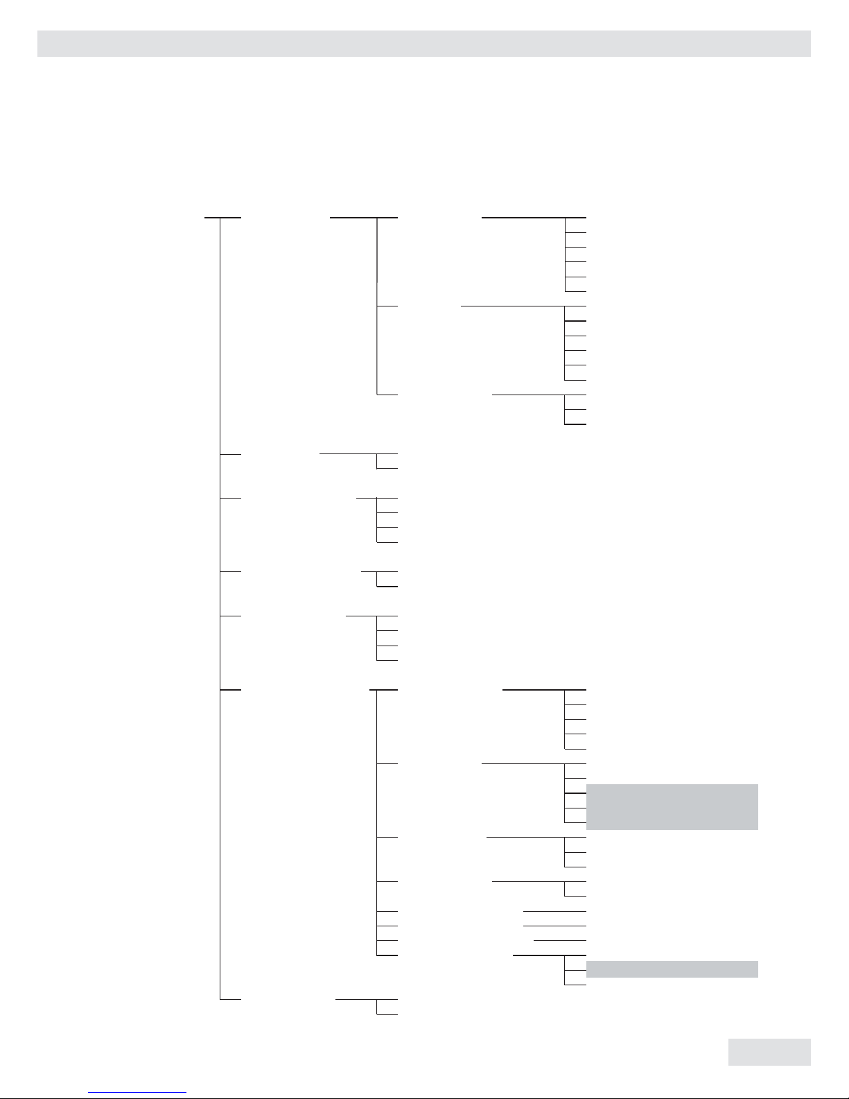
17
Setup Menu 1. Serial COM 1.1 Baud rate 1.1.1 600
1.1.2 1,200
1.1.3 2,400
1.1.4 4,800
1.1.5 9,600 •
1.1.6 19,200
1.2 Parity 1.2.1 7-bit-None
1.2.2 7-bit-Odd
1.2.3 7-bit-Even •
1.2.4 8-bit-None
1.2.5 8-bit-Odd
1.2.6 8-bit-Even
1.3 Print option 1.3.1 Short •
1.3.2 Long/block
1.3.3 Continuous
2. Backlight 2.1 On •
2.2 Off
3. Auto Power Off 3.1 No options •
3.2 5 Min.
3.3 10 Min.
3.4 15 Min.
4. Standby Options 4.1 On •
4.2 Off
5. Adapter Filter 5.1 Very stable conditions
5.2 Stable conditions •
5.3 Unstable conditions
5.4 Very unstable conditions
6. ADC Configuration 6.1 Decimal point 6.1.1 0
6.1.2 1
6.1.3 2
6.1.4 3
6.1.5 4
6.2 Basic unit 6.2.1 g
6.2.2 kg
6.2.3 lb • For some countries,
6.2.4 oz these units
6.2.5 t are disabled
6.3 Step width 6.3.1 1
6.3.2 2
6.3.3 5
6.4 e<>d frame 6.4.1 On
6.4.2 Off •
6.5 Adjust FSD (span) 6.5.1 (Enter FSD weight)
6.6 Calibration weight 6.6.1 (Enter CAL weight)
6.7 Linearisation weight 6.7.1 (Enter Lin weight)
6.8 Calibration unit 6.8.1 g
6.8.2 kg •
6.8.3 lb
7. Reset Menu 7.1 Do not restore
7.2 Restore
• = Factory setting
18
Miras 2
18
Application Programs
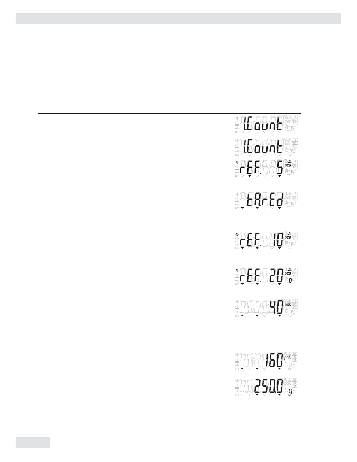
Counting
Step Key (or instruction) Display
a. Select application program (Fn/Up) > 2 sec
b. Select “Counting” (Fn/Up) or (G/N/Down)
repeatedly
c. Press Print/Enter. (Print/Enter)
Display shows reference piece
selection menu.
Counting is blinking.
d. Automatically the display
will show the reference pieces. (Tare/Right)
Place container and press Tare
if required (display “tared”).
e. Select reference sample quantity: (Fn/Up) or (G/N/Down)
5, 10, 20, 50 or 100, and put repeatedly
the reference on the scale.
(quantity flashes)
f. Press Print/Enter . Place reference sample on scale
Now “O” flashes. Automatic optimization is
active. (Print/Enter)
g. Place more reference samples
on scale (The number is
x+2 ~ 2x times the reference
pieces (x) selected in step e.)
When the sample is still, the
reference sample weight is calculated.
The flashing “O” goes out.
h. Place uncounted parts/samples
on the scale
i. Toggle between reference piece weight, (G/N/Down)
total weight, and total pieces.
j. Unload the scale
k. Counting application: Clear (Zero/Left) > 2 sec
Miras 2
19
19
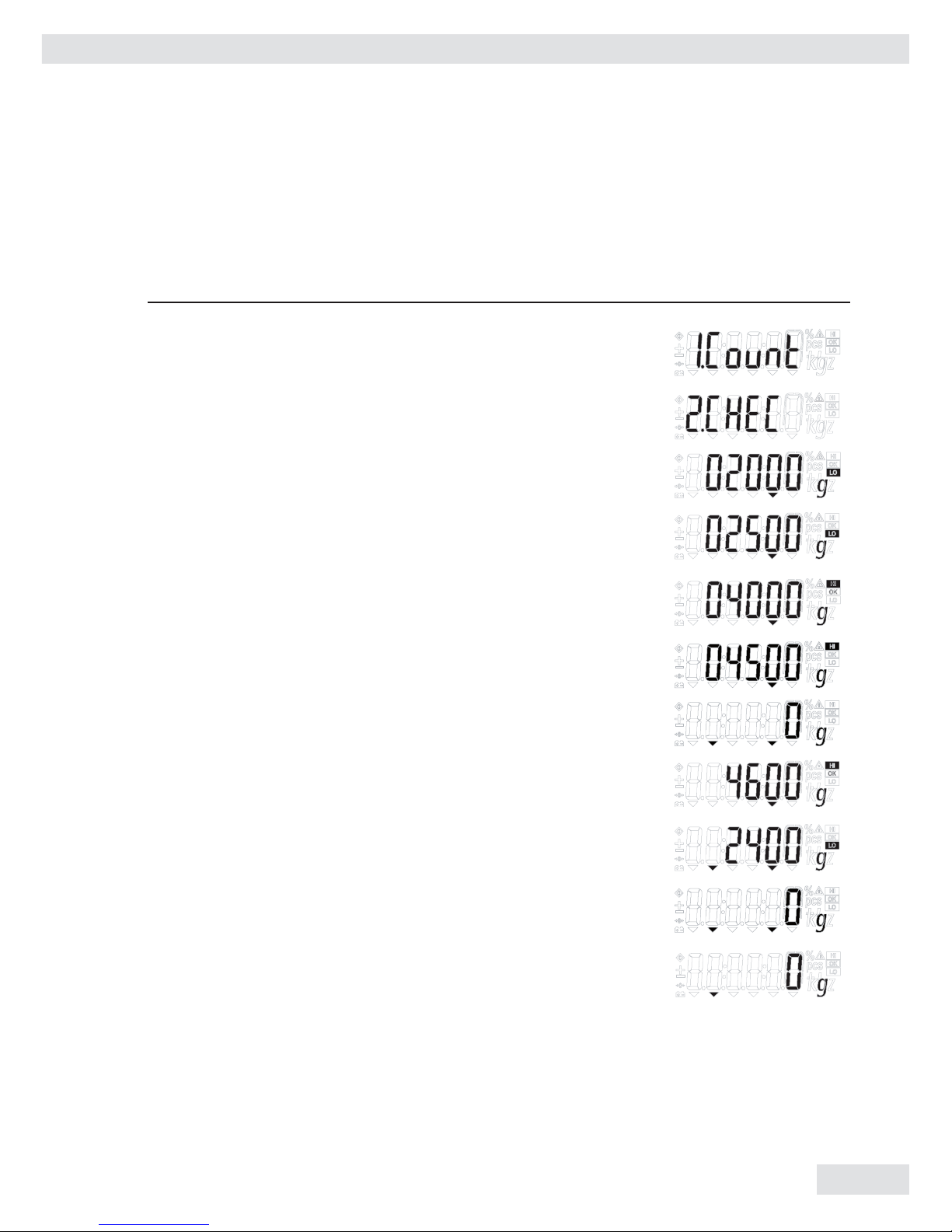
Check Weighing
Step Key (or instruction) Display
a. Select application program (Fn/Up) > 2 sec
b. Select “Checkweighing” (Fn/Up) or (G/N/Down)
repeatedly
c. Press Print/Enter to confirm. (Print/Enter)
“LO” flashes.
d. Set lower limit (Fn/Up) or (G/N/Down) and/or
(Zero/Left) or (Tare/Right)
e. Press Print/Enter to confirm (Print/Enter)
and save. “HI” flashes
f. Set upper limit, (G/N/Down) and/or
and then press Print/Enter. (Zero/Left) or (Tare/Right)
g. Press Print/Enter to confirm (Print/Enter)
and save.
h. Place the sample on the scale.
Display shows the difference
and HI/LO symbol
i. Unload the scale
j. Checkweighing application: Clear (Zero/Left) > 2 sec
20
Miras 2
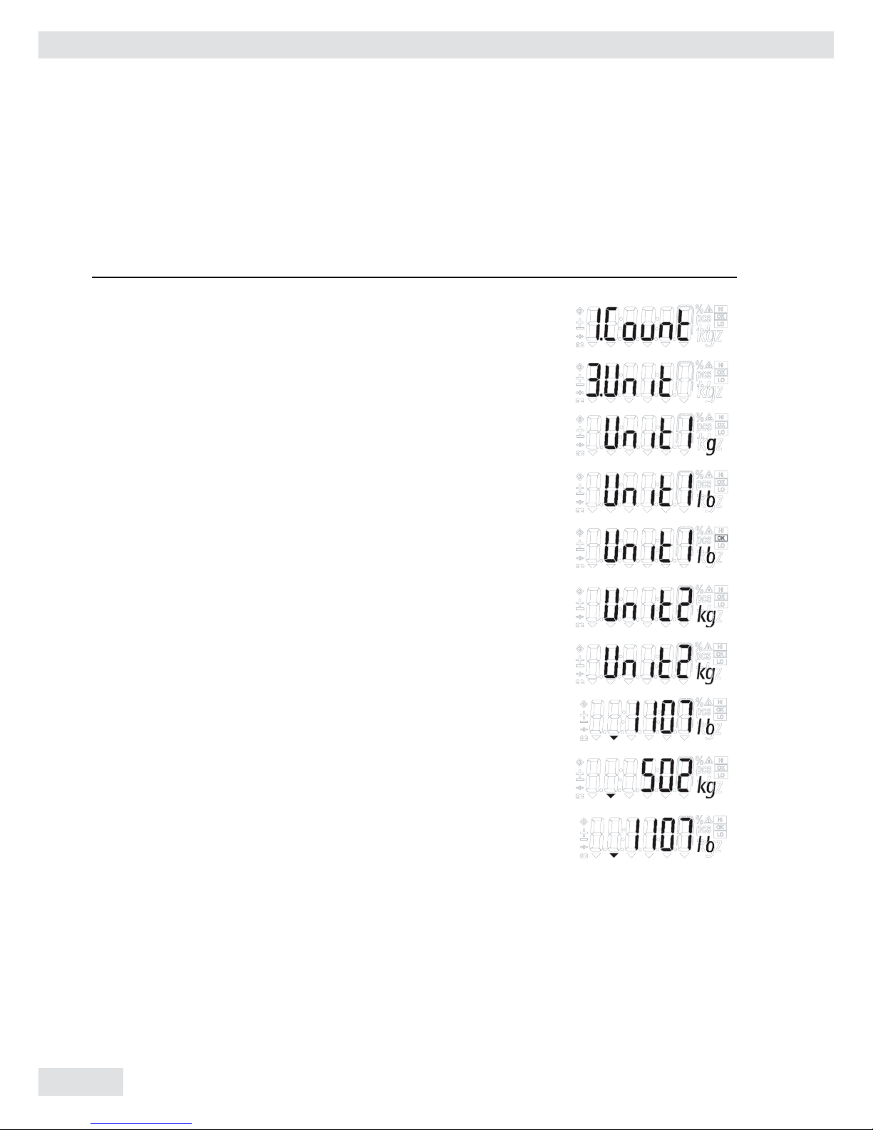
Toggling between Weight Units
Step Key (or instruction) Display
a. Select application program (Fn/Up) > 2 sec
b. Select “Toggling Weight Units” (Fn/Up)
repeatedly
c. Confirm selection (Print/Enter)
d. Select weight unit 1 (Fn/Up)
e. Confirm weight unit 1 (Print/Enter)
f. Select weight unit 2 (Fn/Up)
g. Confirm weight unit2 (Print/Enter)
h. Place sample on the scale
i. Toggle weight unit (Fn/Up)
j. Unit toggling application: (Zero/Left) > 2 sec
Clear (unit changes to basic
unit set)
20
Miras 2
21
21
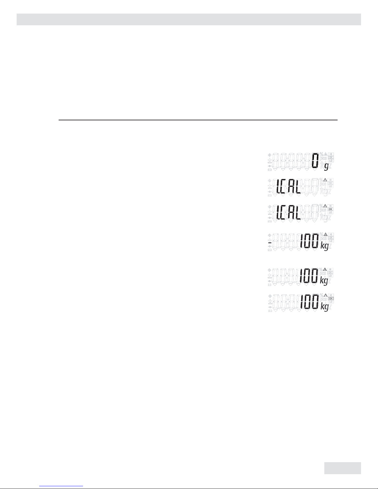
Calibration/Span Adjustment
Calibrate the Scale
Step Key (or instruction) Display
a. Switch on the scale (On/Off)
b. Zero the scale (Zero/Left)
c. Select calibration/linearization (Tare/Right) > 2 sec
mode
d. Select calibration (Fn/Up)
repeatedly
e. Confirm/start calibration. (Print/Enter)
After the zero point is stored,
the required calibration weight
is displayed
f. Place the required weight
on the scale
g. If the weight is applied within (Print/Enter)
the defined time limit and
tolerance, the “OK” symbol
is displayed.
Press “(Print/Enter)” to confirm
and save calibration.
(To exit calibration press
(Zero/Left) > 2 sec)
22
Miras 2
22
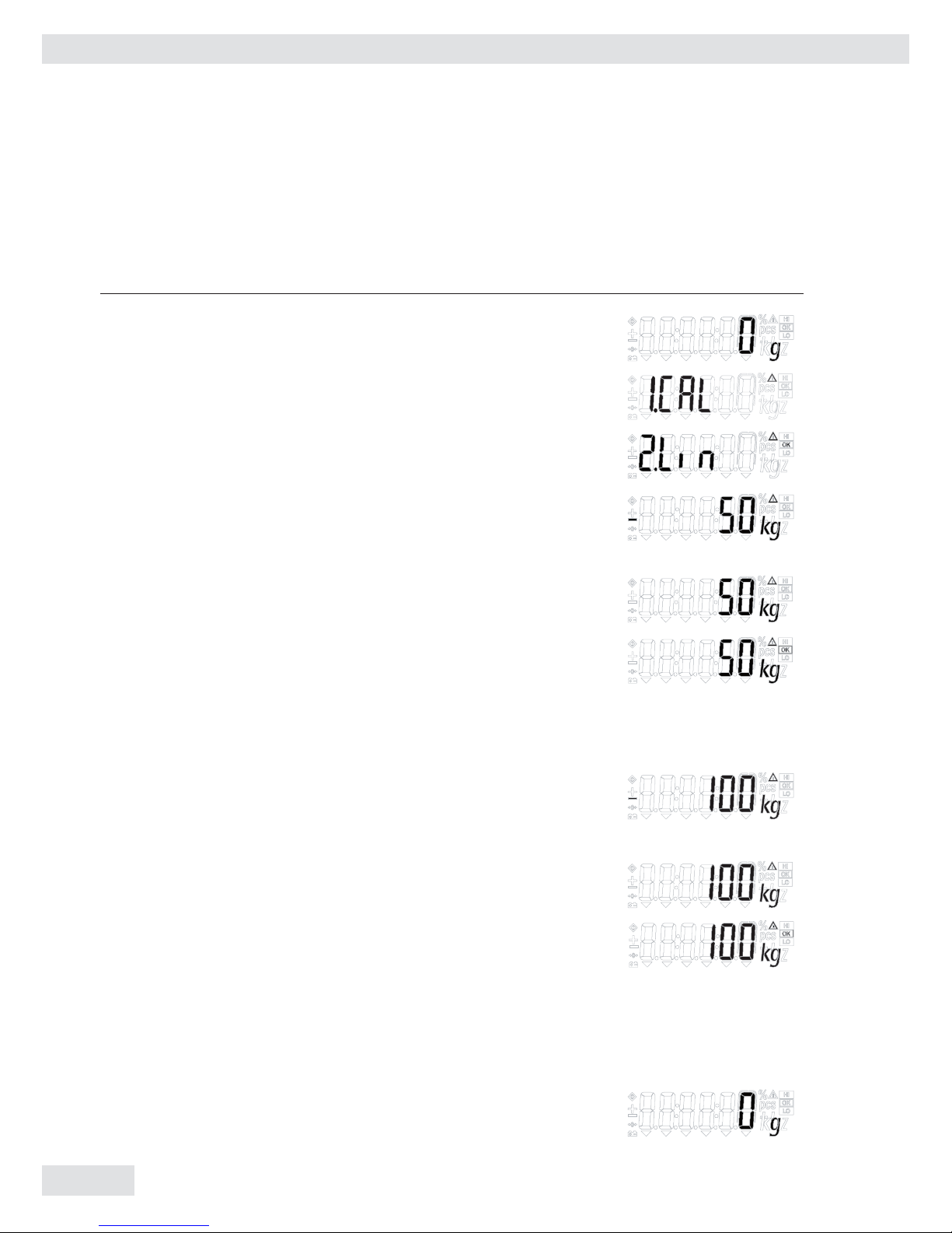
Linearize the Scale
Step Key (or instruction) Display
a. Switch on the scale (On/Off)
b. Zero the scale (Zero/Left)
c. Select calibration/linearization (Tare/Right) > 2 sec
mode
d. Select linearization (Fn/Up) or (G/N/Down)
repeatedly
e. Confirm/start linearization (Print/Enter)
After the zero point is stored,
the required linearization
weight is displayed.
f. Place the required weight on
the scale
g. If the weight is applied within (Print/Enter)
the defined time limit and tolerance,
the “OK” symbol is displayed.
Press “(Print/Enter)” to confirm
and save calibration. (To exit
linearization, press (Zero/Left) > 2 sec)
h. The next linearization weight
will be shown on the display
after confirmation of the
previous linearization weight.
i. Place the required weight
on the scale.
j. If the weight is applied within (Print/Enter)
the defined time limit and
tolerance, the “OK” symbol
is displayed. Press “(Print/Enter)”
to confirm and save calibration.
(To exit linearization,
press (Zero/Left) > 2 sec)
k. Remove the linearization weight
l. Linearization complete

Miras 2
23
SBI Interface Protocol Description
Output format with 22 characters
The following data block format is output:
I I I I I I V W W W W W W W W W U U U CR LF
I : ID W : Weight value
V : +/– sign U : Unit
ID Codes
S t a t Indicates a special weighing platform status, e.g., initialization, self-test,
adjustment/calibration
N Indicates net or gross value
N 1 Indicates net value with 1
st
tare memory assigned (not main tare)
N 2 Indicates net value with 2
nd
tare memory assigned (not main tare)
S / N Indicates equipment serial number
M o d e l Indicates equipment model
Plus/Minus Sign
+ Plus sign
– Minus sign
Space (i.e., no plus or minus sign; if weight value is 0 or if output does not include a
weighed value)
Unit No stable parameter.; no weighed value
g Grams
k g Kilograms
l b Pounds
o z Ounces
t Tons
Special Codes
The data block may contain special information.
Special status-dependent codes:
1 2 3 4 5 6 7 8 9 10 11 12 13 14 15 16 17 18 19 20 21 22
S1 S2 CR LF
The following status codes are output for “S1” and “S2”:
: Taring
C : Internal calibration
- - : All numerals shown in stable readout
H : Overload
L : Underload
23
24
Miras 2
Special Error-Dependent Codes:
1 2 3 4 5 6 7 8 9 10 11 12 13 14 15 16 17 18 19 20 21 22
E R R n n1 n2 CR LF
n – n3 contains an error code of up to 3 digits.
Data Input Formats
You can enter certain commands to control weighing platform functions through the SBI
interface.
As with data output, data is input as 7-bit ASCII characters; hardware and protocol configuration are identical to those for data output.
Formats:
ESC K CR LF
ESC K K1 – CR LF
ESC : Escape
K : Command character
K1 : 2
nd
command character (number)
- : Underline
CR : Carriage return
LF : Line feed
24
Miras 2
25
The CR and LF characters do not have to be transmitted in the data string.
Control Commands
ESC P CR LF Print, auto print: initiate / stop
ESC T CR LF Zero/Tare – combination
ESC V CR LF Zero the weighing platform
ESC U CR LF Tare the weighing platform
ESC S CR LF Reset
ESC O CR LF Lock keyboard
ESC R CR LF Unlock keyboard
ESC x 1 _ CR LF Output model name
ESC x 2 _ CR LF Output serial number
Adaptation to Ambient Conditions
ESC K CR LF Very stable
ESC L CR LF Stable
ESC M CR LF Unstable
ESC N CR LF Very unstable
25
26
Miras 2
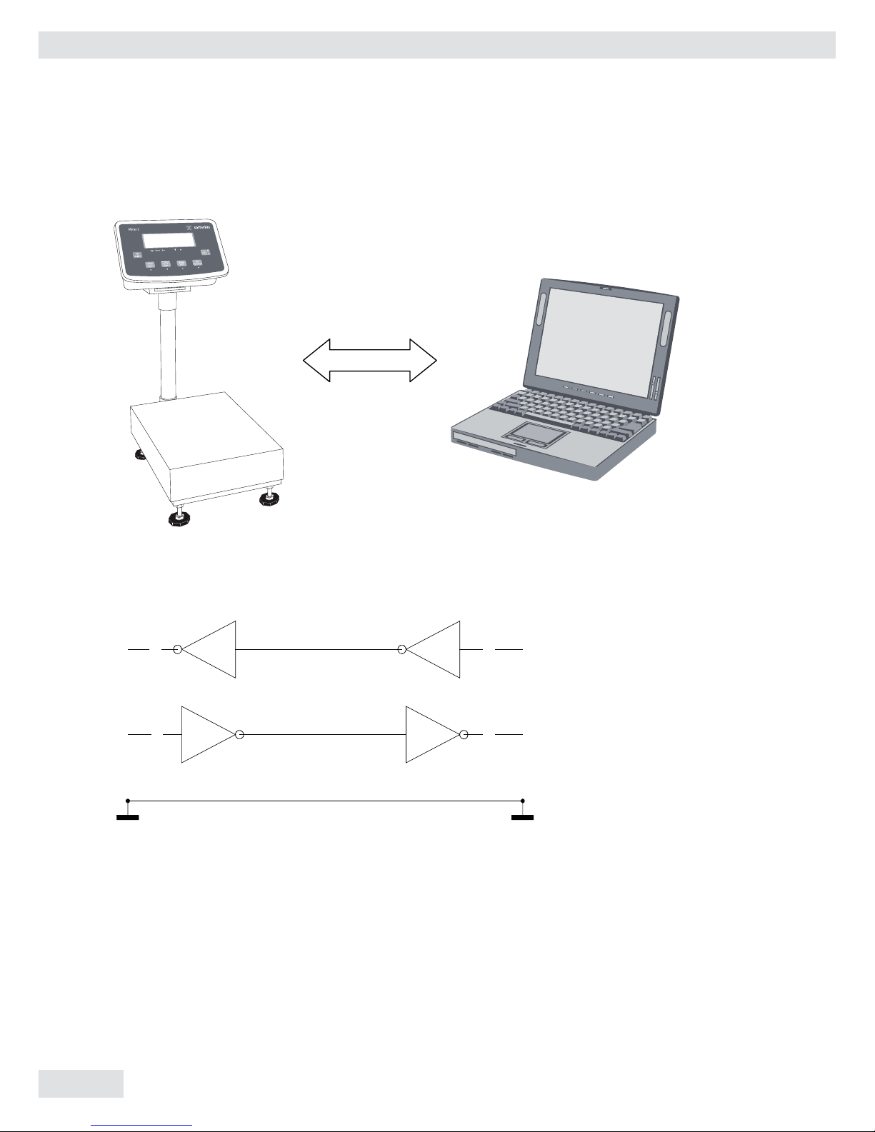
RS-232 Interface Diagram
Diagram for interfacing a computer or different peripheral device to the scale using
RS-232 cable length up to 15 m.
26
TXD RXD
1 3
GND
GND
TXDRXD
2 2
57
DB 25 DB 9
3
2
5
Miras 2
27
Print Formats
The print output can be configured for three modes: short mode (option 1.3.1), long/
block mode (option 1.3.2) and continuous mode (option 1.3.3). The SBI interface,
explained in the section above, is available in all modes. Sample print outputs are given
below for all three printing options in different weighing modes.
Note: To configure serial communication settings and print output options, please refer
to “Configuration (Setup menu)”.
Refer to “Application Programs” to configure the display and control unit for different
weighing modes.
2727
Printing Options
Mode of operation Short print Block print (long print) Continuous mode
Normal weighing
mode
Net weight Gross weight
(if tare is active)
Tare weight
(if tare is active)
Net weight
Gross weight
(if tare is not active)
or
Net weight
(if tare is active)
Counting mode Net weight
Pcs
Ref. weight
Gross weight
(if tare is active)
Tare weight
(if tare is active)
Net weight
Pcs
Ref. weight
Pcs (as default)
Pressing the Gross/Net key
switches
to:
Gross weight
(if tare is not active)
or
Net weight
(if tare is active)
Checkweighing
mode
Net weight
Chk OK/LO/HI
Gross weight
(if tare is active)
Tare weight
(if tare is active)
Net weight
Chk OK/LO/HI
LL (lower limit)
HH (upper limit)
Press key to toggle between:
Gross weight (with unit 1)
and
Gross weight (with unit 2)

28
Miras 2
a. Print Output: Expansion of Abbreviations
N Net weight
G Gross weight
T Tare weight (appears in block printing mode, if tare is not zero)
Chk. Checkweighing status (If checkweighing application is selected)
OK Ok (checkweighing mode, if the placed weight is in the range set)
HI High
LO Low
LL Lower limit (checkweighing)
HL Higher limit (checkweighing)
W.Ref. Reference weight (counting application)
Pcs Number of units on the pan
g Weight in grams
kg Weight in kilograms
+ Appears if the value is greater than or equal to zero
– Appears if the value is less than zero
28

Miras 2
29
b. Sample print outputs in different
applications
1. Short printing mode:
1.1 Normal weighing
G + 200 g
1.2 Counting
N + 400 g
Pcs 10 pcs
W.Ref.
40 g
1.3 Checkweighing
Ex 1: If the weight on the pan is <10%
of lower limit set.
N + 0 g
Chk.
Ex 2: If the weight on the pan < lower
limit set.
N +
100 g
Chk.
LO
Ex 3: If the weight on the pan is
between the set limits.
N + 200 g
Chk. OK
Ex 4: If the weight on the pan > upper
limit set.
N + 410 g
Chk. HI
1.4 Unit toggling
Ex 1: Before toggle key is pressed
G + 300 g
Ex 2 : After unit is toggled to
kilograms.
G + 0.300 kg
2. Block printing mode:
2.1 Normal weighing
Ex 1: If tare is zero
G + 200 g
Ex 2: If tare is not zero
G + 100 g
T + 50 g
N + 50 g
2.2 Counting mode
Ex 1: If tare is zero.
G + 400 g
Pcs
10 pcs
W.Ref.
40 g
Ex 2: If tare value is set.
G + 440 g
T + 400 g
N +
80 g
Pcs
2 pcs
W.Ref. 40 g
2.3 Checkweighing mode
Ex 1: If the weight on the pan is <10%
of lower limit set, with zero tare.
G + 0 g
Chk.
LL 200 g
HL 400 g
Ex 2: If the weight on the pan < lower
limit set, with zero tare.
G + 100 g
Chk. LO
LL
200 g
HL
400 g
Ex 3: If the weight on the pan is
between the set limits, with zero tare.
G + 200 g
Chk. OK
LL
200 g
HL
400 g
29

30
Miras 2
Ex 4: If the weight on the pan > upper
limit set.
G + 410 g
Chk. HI
LL 200 g
HL 400 g
Ex 5: If the weight on the pan is <10%
of lower limit set, with a set tare value.
G + 400 g
T + 400 g
N +
0 g
Chk.
LL 200 g
HL 400 g
Ex 6: If the weight on the pan < lower
limit set, with a set tare value.
G + 800 g
T + 400 g
N + 400 g
Chk. OK
LL
200 g
HL 400 g
Ex 7: If the weight on the pan > upper
limit set, with tare value set.
G + 810 g
T + 400 g
N + 410 g
Chk. HI
LL 200 g
HL 400 g
2.4 Unit toggling
Ex 1: Before toggle key is pressed.
G + 300 g
T + 200 g
N + 100 g
Ex 2 : After unit is toggled to kilograms.
G + 0.300 kg
T + 0.200 kg
N + 0.100 kg
3. Continuous printing mode
3.1 Normal weighing
Ex 1: If tare is not active
G + 200 g
Ex 2 : If tare value is present.
N + 200 g
3.2 Counting mode
default:
Pcs 2 Pcs
Ex 1: If tare is not active (G/N key)
G + 200 g
Ex 2 : If tare value is present. (G/N
key)
N + 200 g
3.3 Checkweighing
Ex 1: If tare is not active
G + 200 g
Ex 2 : If tare value is present.
N + 200 g
3.4 Unit toggling
Output 1: Before toggle key is pressed
G + 300 g
Output 2: After the unit is toggled to
kilograms.
G + 0.300 Kg
30