

Sartorius IS...-X Series, IS2CCE-SX, IS06BBE-SX, IS6CCE-HX, IS6CCE-SX Operating Instructions Manual
...Page 1

Operating Instructions
Sartorius Intec IS-X
Models IS06BBE-SX, IS2CCE-SX, IS6CCE-HX,
IS6CCE-SX, IS12CCE-SX, IS16EDE-HX, IS34EDE-HX, IS64EDESX, IS150IGG-HX, IS300IGG-HX and Verifiable Models
Weighing Platforms for Use in Hazardous Areas/Locations
98648-009-42
Page 2

Contents
Contents
2 Intended Use
3 Operating Limits
4 Tables of Specifications
9 Pin Assignment Chart
10 Troubleshooting Guide
11 Accessories (Options)
12 General View of the Equipment
15 Dimensions (Scale Drawings)
20 Declarations of Conformity
26 Certificates for Operation of the
Weighing Platform in
Hazardous Areas
Symbols
The following symbols are used in these
nstructions:
§ indicates required steps
$ indicates steps required only under
certain conditions
> describes what happens after you have
performed a certain step
– indicates an item in a list
! indicates a hazard
Make sure you observe the warning
and safety information in its entirety
during installation and operation, as
well as while performing maintenance
and repair work on the equipment. It is
important that all personnel using the
equipment understand this information,
and have access to it at all times.
The warning and safety information
is contained in the 11-language
installation manual included with the
equipment.
The warning and safety information
can be supplemented by the equipment
operator. Make sure all operating
personnel are informed of any additions
to these instructions.
Intended Use
The series IS...-.X models are precision
weighing platforms for weighing
samples in hazardous areas/locations.
Series IS...-.X equipment and connected
accessories are intended to be used
exclusively for weighing.
Instructions for installing the
equipment and putting it into
operation are contained in the enclosed
11-language installation manual.
Important Note:
The verifiable models („IS...-.XCE“) can
be verified for use as a scale only when
connected to a display and control unit,
indicator or terminal.
The following features make the
IS...-.X weighing platforms ideal for
use as inspection, measuring and test
instruments in quality management
systems:
– isoTEST calibration and adjustment
function
– ISO/GMP-compliant documentation
functions
IS...-.X weighing platforms save work
and speed up both simple and complex
routine procedures through the
following features:
– Ultrafast response times
– Connection to a PC in a PLC or other
control system
IS...-.X weighing platforms meet the
highest requirements placed on the
accuracy and reliability of weighing
results through the following features:
– Efficient filtering-out of vibration
– Stable and reproducible results
– Rugged, durable weighing system
– Weighing platform and accessories
approved for use in hazardous
areas/locations (see the table in the
11-language installation instructions)
All power supplies or AC adapters may
be connected only to an electrical
outlet (mains supply) with at least 90V
and no more than 264V (48 – 62 Hz).
Set up the explosion-protected IS...-
.X series weighing platform and
its accessories in accordance with
acknowledged technical regulations.
You must also comply with the national
laws and safety regulations of your
country.
Data Output
The weighing platform is equipped
with an RS-485 data interface (RS-232
available on request) which can be used
to connect any of the following:
– Printer*
– Peripheral device (such as a computer)*
– Universal remote switch
* connected through a Zener barrier
(see „Accessories“)
Hotline/Technical Advice
on Applications
Phone: +49 (0) 40/67960444
Fax: +49 (0) 40/67960474
E-mail: technical.support.hh
@sartorius-intec.com
2
Operating Instructions IS-X
Page 3

Operating Limits
Operating Limits
Overload Capacity
Thanks to the rugged construction of
Sartorius Intec weighing platforms, the
weighing system will not be damaged
if the maximum weighing capacity is
occasionally exceeded.
The table below lists the maximum
overload capacity of each weighing
platform model:
IS06BBE-SX.. IS2CCE-SX.. IS6CCE-SX..
IS6CCE-HX..
3 kg 12 kg 25 kg
IS16EDE-HX IS150IGG-HX,
IS34EDE-HX IS300IGG-HX
IS64EDE-SX
130 kg 600 kg
Shock Resistance
Even though Sartorius Intec weighing
platforms feature highly rugged
construction, there are some limits.
Avoid exposing the system to falling
objects, side impact, or shocks. The
weighing platform meets the mechanical
requirements of IEC 68 Part 2-27.
Notes on Integration into Conveyor
Systems
The weighing platform is suitable for
installation in conveyor systems. Make
sure to observe the following notes as
well as the equipment dimensions when
choosing components to be mounted
on your weighing platform
(see „Dimensions (Scale Drawings)“ in
this manual).
Any moving or rotating parts intended
to be permanently attached to the load
plate must be designed so that they
cannot affect the weighing results. For
example, rotating mechanisms must be
properly balanced.
The load plate must be clear on all
sides so that any parts or any dirt
that falls will not create a connection
between the weighing platform and
any permanently mounted preload
components.
Any cables or tubing between the
weighing platform and other equipment
must not apply any force to the
weighing platform. Make sure that
cables do not touch the load plate.
Special care must be taken to prevent
the build-up of static electricity
caused by moving parts (such as roller
conveyors).
Preload Range (Zero-setting Range)
The weight of components permanently
attached to the weighing platform is
known as the „preload.“ The preload
is electronically compensated up
to a defined value. Thus the entire
weighing capacity is available, and it
is possible to zero or calibrate/adjust
the weighing system (with external
weights). A preload heavier than the
defined value may result in a reduction
of the weighing capacity.
The maximum preload that can
be compensated depends on the
specification block configured (refer
to the tables of specifications below).
Components attached to the weighing
platform must be installed before the
weighing platform is connected to
power.
Configuring the Weighing Platform
The weighing platform can be
configured to meet individual
requirements, such as weighing in
international units, weighing in
unfavorable ambient conditions,
or external electronic processing
of weight values. This means the
final configuration of a unit can be
performed by the weighing equipment
dealer or the end user.
The weighing platform is adapted
for individual requirements using the
configuration menu in the connected
display and control unit or indicator.
The weighing platform can also be
configured using a connected
computer running the Sartorius Intec
configuration program
(see „Accessories“).
Options Available for
Weighing Range Configuration
SuperRange
This range divides the weighing
capacity of the platform into 50.000
intervals, an exceptionally high
resolution. The readability is identical
over the entire weighing range
(for example, 1 g).
SingleRange
The weighing range is divided into up
to 50.000 intervals. The readability is
identical over the entire weighing range
( for example, 10 g).
Multi-interval/DualRange
Intervals with adjusted
accuracy. These functions divide the
weighing capacity into as many 3
weighing ranges, each with a different
readability.
The weight readout is shown with
different levels of accuracy in each
range. The platform changes from one
range to another automatically when
the load on the platform is changed
(the readability in each range is listed in
the tables of specifications below).
Once the platform has been tared, the
highest possible resolution is available
even if the weighing platform is loaded.
The configuration options available
for each weighing platform are listed
below, in the section entitled „Tables of
Specifications.“
Operating Instructions IS-X
3
Page 4

Tables of Specifications
Tables of Specifications
Model IS06BBE-SX IS2CCE-SX IS6CCE-HX IS6CCE-SX IS12CCE-
SX
Readability g 0.001 0.01 0.01 0.1 0.1
.........
Weighing capacity g 620 2200 6200 6200 12,000
Max. overload capacity kg 3 12 12 25 25
Tare range (subtractive) g – 620 – 2200 – 6200 – 6200 – 12000
Preload (can be electronically g 93 110 – 1240 1200
compensated without reducing the weighing capacity)
Max. preload at start of isoTEST g 110 1300 5200 6400 10000
calibration/adjustment
(platform must be zeroed)
Repeatability <±g 0.001 0.01 0.01 0.05 0.05
Linearity <±g 0.002 0.02 0.02 0.1 0.2
Sensitivity drift within +10 to +30 °C <±/K 2 • 10
Response time (average) s 1.5 1.5 1.5 1 1
External calibration weight g 500 (E2) 2000 (F1) 5000 (E2) 5000 (F2) 5000 (F1)
(of at least accuracy class...)
Load plate dimensions mm Ø 130 218 x 200 218 x 200 218 x 200 218 x 200
Platform dimensions (W x D x H) mm 240x294x86 240x294x86 240x294x86 240x294x86 240x294x86
Net weight, approx. kg 7 7.3 8.4 7.3 7.3
Dust and water protection rating for the housing acc. to EN 60529 IP44
AC power source Power supply model YPS02-X or AC adapter model YPS02-Z (100-240V)
(must be connected by the weighing equipment dealer or a Sartorius Intec service tech-
nician)
Frequency Hz 48 – 62
Allowable ambient operating temperature 0 °C to +40 °C (273 °K to 313 °K; 32 °F to 104 °F)
Operating temperature range +10 °C to +30 °C (or 0 °C to +40 °C; depends on configuration)
Adaptation to ambient conditions By selection of 1 of 4 optimized filter levels
Display update (depends on filter level selected) 0.1 - 0.1 - 0.2 - 0.4 (normal output rate)
Power consumption Average: 25VA
Selectable weight units: Grams, kilograms, carats, pounds, ounces, Troy ounces, Hong Kong taels,
Singapore taels, Taiwanese taels, grains, pennyweights, milligrams, parts per
pound, Chinese taels, mommes, Austrian carats, tola, baht and mesghal
Built-in RS-485 interface (standard equipment; xBPI protocol):8 bits, odd parity; transmission rate: 9600 -
38,400 baud; half-duplex; convertible to RS-232 (SBI protocol): 7 bits, Parity: even,
odd, mark, space; transmission rates: 150 — 19,200 baud; 1 or 2 stop bits, software/
hardware handshake; factory settings: 1200 baud, odd parity, 1 stop bit, hardware
handshake with 2 characters after CTS
Model series Marking (ATEX) Use in IP rating Markings in acc. with FMRC Use in
Zone approval for USA and CSA
approval for Canada
IS.. BBE-.X.. 1, 2 (gas) IP 54 IS CL I, DIV 1, GR A,B,C,D, T4 Class I, Division 1 (gas)
IS.. CCE-.X.. 1, 2 (gas) IP 54 IS CL I, DIV 1, GR A,B,C,D, T4 Class I, Division 1 (gas)
IS… EDE-.X.. 1, 2 (gas) IP 65 IS CL I, DIV 1, GR A,B,C,D, T4 Class I, Division 1 (gas)
20, 21, 22 IP 65 IS CL II,III, DIV 1, GR E,F,G, T4 Class II,III Division 1
IS64EDE-HX.. 1, 2 (Gas) IP 44 IS CL I, DIV 1, GR A,B,C,D, T4
h II 2 G EEx ib IIC T4 CL l, ZONE 1 AEx ib IIC T4 Class I, Zone 1 (gas)
h II 2 G EEx ib IIC T4 CL l, ZONE 1 AEx ib IIC T4 Class I, Zone 1 (gas)
h II 2 G EEx ib IIC T4 CL l, ZONE 1 AEx ib IIC T4 Class I, Zone 1 (gas)
h II 1 D T135°C (dust) (dust+ fibers)
h II 2 G EEx ib IIC T4 CL l, ZONE 1 AEx ib IIC T4 Class I, Zone 1 (gas)
-6
2 • 10-6 2 • 10-6 4 • 10-6 4 • 10
Class I, Division 1 (gas)
-6
IS… IGG-HX 1, 2 (gas) IP 65 and IP67 IS CL I, DIV 1, GR A,B,C,D, T4 Class I, Division 1 (gas)
(dust) (dust + fibers)
h II 2 G EEx ib IIC T4 CL l, Zone 1 AEx ib IIC T4 Class I, Zone 1 (gas)
h II 1 D T135°C 20, 21, 22 IP 65 and IP 67 IS CL II,III, DIV 1, GR E,F,G, T4 Class II,III Division 1
* = factory setting
4
Operating Instructions IS-X
Page 5

Tables of Specifications
HX-Mode IS16EDE-HX IS34EDE-HX IS64EDE-SX IS64EDE-HX IS150IGG-HX IS300IGG-HX
Readability g 0,1 0,1 1 0,1 1 2
Weighing capacity kg 16 34 64 64 150 300
Max. overload capacity kg 130 130 130 130 600 600
Tare range (subtractive) kg – 16 – 34 – 64 -64 – 150 -300
Preload (can be electronically compensated kg 4 4 13 13 20 60
without reducing the weighing capacity)
Max. preload at start of kg ca. 19 ca. 21 ca. 45 45 – -
isoTEST calibration/adjustment
(platform must be zeroed)
Repeatability <±g 0,05 0,1 0,5 0,2 1 2
Linearity <±g 0,2 0,2 1 1 4 8
Sensitivity drift
within +10 to +30 °C <±/K 2 • 10
-6
2 • 10-6 3 • 10
-6
3 • 10
-6
2,5 • 10
-6
2,5 • 10
-6
Response time (average) s 1,5
External calibration weight kg 10 (F1) 10 (F1) 10 (F2) 10 (F1) 50 (F2) 50 (F2
(of at least accuracy class...)
Operating temperature range °C 10...30 10...30 0...40 0...40 0...40 0...40
Load plate dimensions mm 300 x 400 300 x 400 300 x 400 300 x 400 800x600 800x600
Net weight, approx. kg 16 16 16 16 70 70
Dust and water protection rating of the
housing acc. to EN 60529 IP65 IP65 IP65 IP44 IP67 IP67
AC power source Power supply model YPS02-X or AC adapter model YPS02-Z (100-240V) (must be
connected by the weighing equipment dealer or a Sartorius Intec service technician)
Frequency Hz 48 – 62
Allowable ambient operating temperature 0 °C to +40 °C (273 °K to 313 °K; 32 °F to 104 °F)
Operating temperature range +10 °C to +30 °C (or 0 °C to +40 °C; depends on configuration)
Adaptation to ambient conditions By selection of 1 of 4 optimized filter levels
Display update (depends on filter level selected) 0.1 - 0.1 - 0.2 - 0.4 (normal output rate)
Power consumption Average: 25VA
Selectable weight units: Grams, kilograms, carats, pounds, ounces, Troy ounces, Hong Kong taels,
Singapore taels, Taiwanese taels, grains, pennyweights, milligrams,
parts per pound, Chinese taels, mommes, Austrian carats, tola, baht and mesghal
Built-in RS-485 interface (standard equipment; xBPI protocol): 8 bits, odd parity, transmission rate:
9600 - 38,400 baud; half-duplex; convertible to RS-232 (SBI protocol): 7 bits,
Parity: even, odd, mark, space; transmission rates: 150 — 19,200 baud; 1 or 2
stop bits, software/ hardware handshake; factory settings:
1200 baud, odd parity, 1 stop bit, hardware handshake with 2 characters after CTS
* = factory setting
Operating Instructions IS-X
5
Page 6

Tables of Specifications
IS „-.XCE“ Series Verifiable Models
Model IS06 BBE-SXCE IS2 CCE-SXCE IS6 CCE-HXCE
Readability g 0.001 0.01 0.01
Weighing capacity g 620 2200 6200
Max. overload capacity kg 3 12 12
Tare range (subtractive) g – 620 – 2200 – 6200
Preload (can be electronically compensated) g 93 110 –
.........
without reducing the weighing capacity)
Max. preload at start of g 110 1300 5200
isoTEST calibration/adjustment
(weighing inst. must be zeroed)
Repeatability <±g 0.001 0.01 0.01
.........
Linearity <±g 0.002 0.02 0.02
Sensitivity drift within +10 to +30 °C <±/k 2 • 10
Response time (average) s 1.5 1.5 1.5
External calibration weight g 500 (E2) 2000 (F1) 5000 (E2)
(of at least accuracy class...)
Accuracy class K K K
Type . BD BF BF
Verification scale interval g 0.01 0.1 0.1
Minimum capacity acc. to g 0.02 0.5 0.5
prepackage regulations*
Operating temperature range °C 10 to 30 (50 to 86°F) 10 to 30 (50 to 86°F) 10 to 30 (50 to 86°C)
Load plate dimensions mm Ø 130 218 x 200 218 x 200
Platform dimensions (WxDxH) mm 240x294x86 240x294x86 240x294x86
Net weight, approx. kg 7 7.3 8.4
Dust and water protection rating for the housing acc. to EN 60529 IP44
AC power source Power supply model YPS02-X or AC adapter model YPS02-Z (100-240V);
YRB02-Z (rechargeable battery), YPS02-XV24 (24V)
Frequency Hz 48 – 62
Adaptation to ambient conditions By selection of 1 of 4 optimized filter levels
Display update
(depends on filter level selected) 0.1 - 0.1 - 0.2 - 0.4 (normal output rate)
Power consumption Average: 25VA
Built-in RS-485 interface (standard equipment; xBPI protocol): 8 bits, odd parity,
transmission rate: 9600 - 38,400 baud; half-duplex; convertible to
RS-232 (SBI protocol): 7 bits, parity: even, odd, mark,
space; transmission rates: 150 — 19,200 baud; 1 or 2
stop bits, software/hardware handshake; factory settings:
1200 baud, odd parity, 1 stop bit, hardware handshake with 2 characters after CTS
-4
2 • 10-4 2 • 10-4
* = factory setting
6
Operating Instructions IS-X
Page 7

Tables of Specifications
Verifiable Models, IS Series IS16EDE-HXCE IS34EDE-HXCE IS64EDE-SXCE IS150IGG-HXCE IS300IGG-HXCE
Readability in g 0,1 0,1 1 1 20
Weighing capacity in kg 16 34 64** 150** 300**
Max. overload capacity in kg 130 130 130 600 600
Tare range (subtractive) in kg – 16 – 34 – 64 – 150 -300
Preload (can be electronically compensated in kg 4 4 13 20 20
without reducing the weighing capacity)
Max. preload at start of ca. 19 ca. 21 ca. 45 – -
isoTEST calibration/adjustment
(weighing inst. must be zeroed) in kg
Repeatability <±g 0,05 0,1 0,3 1 5
Linearity <±g 0,2 0,2 1 4 8
Sensitivity drift within
+10 to +30 °C <±/K 2 • 10-6 2 • 10-6 3 • 10
-6
2,5 • 10
-6
2,5 • 10
-6
Response time (average) s 1,5 1,5 1,5 1,5 1,5
External calibration weight g 10000 (F1) 10000 (F1) 10000 (F2) 50000 (F2) 100000(F2)
(of at least accuracy class...)
Accuracy class K K K K K
Type BF BF HC BF BF
Verification scale interval g 1 1 10 10 20
Minimum capacity acc. to g 5 5 50 50 100
prepackage regulations*
Mindestlast nach FPV g 150 150 - - Operating temperature range °C 10...30 10...30 10...30 10...30 10...30
(50 to 86°F) (50 to 86°F) (50 to 86°F) (50 to 86°F) (50 to 86°F)
Load plate dimensions mm 300 x 400 300 x 400 300 x 400 800x600 800x600
Net weight, approx kg 16 16 70 70 70
Dust and water protection rating of the
housing acc. to EN 60529 IP65 IP65 IP65 IP67 IP67
AC power source
Power supply model YPS02-X or AC adapter model YPS02-Z (100-240V); YRB02-Z (rechargeable battery), YPS02-XV24 (24V)
Frequency Hz 48 – 62
Adaptation to ambient conditions By selection of 1 of 4 optimized filter levels
Display update (depends on filter level selected) 0.1 - 0.1 - 0.2 - 0.4 (normal output rate)
Power consumption Average: 25VA
Built-in RS-485 interface (Standard equipment; xBPI protocol): 8 bits, odd parity,
transmission rate: 9600 - 38,400 baud; half-duplex; convertible to
RS-232 (SBI protocol): 7 bits, parity: even, odd, mark,
space; transmission rates: 150 — 19,200 baud; 1 or 2
stop bits, software/hardware handshake; factory settings:
1200 baud, odd parity, 1 stop bit, hardware handshake with 2 characters after CTS
* = factory setting
** = variable weight unit kg, t
Operating Instructions IS-X
7
Page 8
Pin Assignment Chart
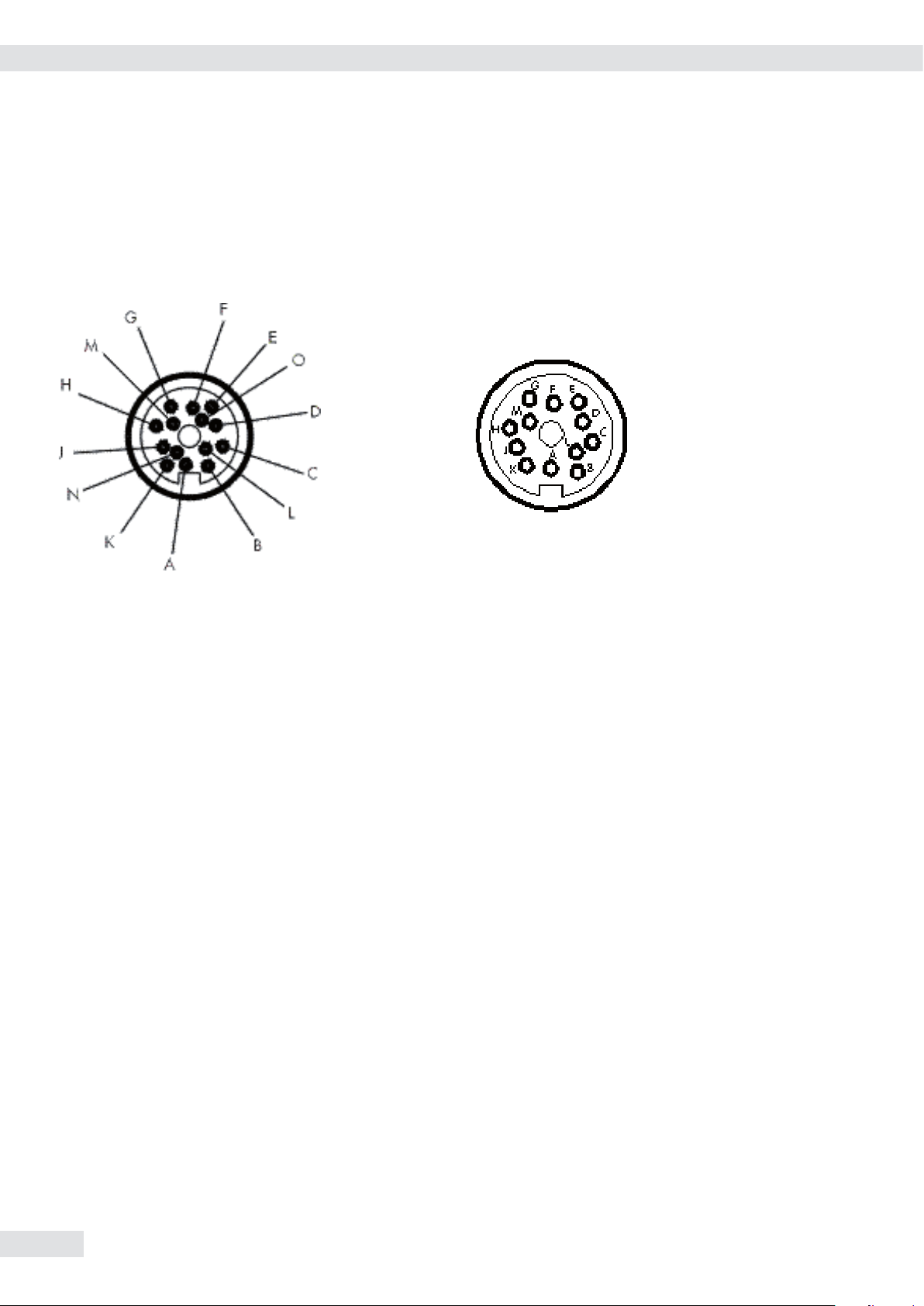
Pin Assignment Chart
Female Interface Connector:
14-contact round female connector with screw lock hardware for cable gland
Pin Assignments
Platform: Zener barrier (output in safe area)
YDI01-Z, YDI02-Z, YDI03-Z:
14-pin 12-pin Signal RS-232
1
) Signal RS-485
Round male connector Barrier (SBI and xBPI) (xBPI)
G A Control output „heavier“ Control output „heavier“
K B Data output (TxD) RxD – TxD – N
J C Data input (RxD) RxD – TxD – P
N D Data terminal ready (DTR)
M E Signal GND Signal GND
F G
3
) Control output „lighter“ Control output „lighter“
A H Clear to send (CTS)
E J
3
) Control output „equal“ Control output „equal“
O – Universal switch 2) Universal switch 2)
D L
3
) Control output „set“ Control output „set“
Provide a low-resistance connection between shield and connector casing.
1
) RS-232-interface available on request
2
) Function: see „External Universal Remote Switch“ in the section entitled „Extra Functions.“
3
) YDI03-Z only
Important:
! Only electrical apparatus with a max. voltage Um f 250V may be connected to the Zener barrier. The Zener voltage UZ is 12V.
8
Operating Instructions IS-X
Page 9

Troubleshooting Guide
Troubleshooting Guide
Problem Possible cause(s) Solution
No segments are shown No AC power is available Check the AC power supply; con-
nect
on the display The power supply or AC adapter the power supply/AC adapter to power
is not connected
Device not used > 5 minutes Turn on the display and control
(now in stand-by mode) unit/indicator using the On/Off switch
Weight display shows “ H“ The load exceeds the weighing capacity Unload the weighing platform
Weight display The load plate is Place the load plate
shows “L“ or “ Err 54“ not in position on the platform
Weight display Data output not compatible Change the menu settings
shows “Err 01“ briefly with output format in device setup menu
Weight display One of the conditions for calibration Calibrate only when zero is dis-
played
shows “Err 02“ briefly was not met Zero the weighing platform
Load on weighing platform Unload the weighing platform
Weight display Calibration/adjustment could not Allow the scale to warm up and
then
shows “Err 03“ briefly be performed within repeat calibration/adjustment
the required time period
Error code “Err 08“ The load on the weighing platform Check whether your configuration
is too heavy to allow the platform to be zeroed meets the zero-setting point
requirements
Error code “Err 09“ Gross value < zero and weighing Zero the weighing platform
platform is unloaded, but cannot
be tared
Error code “Err 10“ Data in application tare memory Clear the application tare
when attempted to clear lower
tare memory
Error code “Err 12“ Attempt to write data in application Check configuration memory first
tare memory when blocked (menu item 2 2 x)
Value not permitted for Check value entered
manual tare input
Error code “Err 17“ Internal calibration/adjustment not possible Reduce preload or
because preload is too high Select a different configuration
Error code “Err 19“ The available weighing capacity Reduce preload or
is too low; max. capacity select a different configuration
reduced by high preload
The special code “A“ remains Press a key
on the display; none of the keys has
been pressed since the equipment
was switched on
The weight readout Unstable ambient conditions Set up the weighing platform
changes constantly (too much vibration, or the in a different area, or
weighing platform is exposed access the Setup menu to change
to a draft) device configuration
A foreign object is caught Remove the foreign object
between the load plate and
the weighing platform housing
The weight readout is The weighing platform has not been calibrated Perform calibration/adjustment
obviously wrong The platform was not tared before weighing Tare before weighing
If any other errors occur, please contact your local Sartorius Intec office or dealer or the Sartorius Intec Service Center.
Operating Instructions IS-X
9
Page 10

Accessories
Accessories (Options)
Order no.:
Power supply, flameproof, for use in hazardous area/location
100 - 240V EU YPS02-XDR
GB YPS02-XGR
USA/CDN YPS02-XKR
AC adapter for use outside the hazardous area/location
100 - 240V EU YPS02-ZDR
GB YPS02-ZGR
USA/CDN YPS02-ZKR
In the safe area (outside the hazardous area/location), accessories can be connected
through a Zener barrier.
Order no.:
Data output: RS-232 for IS-X YDO55IS-X
Data output: TTY/10mA for IS-X YDO01F-X
Zener barrier YDI01Z
(2 RS-485 data lines) for
connection in a bus network
Zener barrier YDI02Z
(4 RS-232 data lines)
Zener barrier YDI03Z
(4 RS-232 data lines
and 4 control lines)
Configuration program (on diskette) for IS-X weighing platform YAD01IS
(PC, DOC) without interface cable
Sartonet cable 6906926
Sartonet connection box 72583
Round plug-in connector 69Y03166
For customized cable solutions or accessories, please contact the Sartorius Intec.
10
Operating Instructions IS-X
Page 11

General View of the Equipment
2
3
4
6
8
10
11
1
5
7
9
3
6
10
11
7
12
9
8
IS06BBE-SX
General View of the Equipment
IS2CCE-SX, IS6CCE-HX, IS6CCE-SX, IS12CCE-SX
Pos. Designation
1 Draft shield cover
2 Glass draft shield
3 Load plate
4 Pan support
5 Shield ring
6 Lug for attaching an antitheft locking device
7 Leveling foot
8 DC jack
9 Data interface (RS-485)
10 Menu access switch (under protective threaded cap)
11 Level indicator
12 Pan draft shield (models IS2CCE-SX, S6CCE-HX only)
Operating Instructions IS-X
11
Page 12

General View of the Equipment
IS16EDE-HX, IS34EDE-HX, IS64EDE-SX
Pos. Designation
1 Level indicator
2 DC jack
3 Data interface (RS-485)
4 Leveling feet
5 Weighing platform
6 Load plate
12
Operating Instructions IS-X
Page 13

IS150IGG-HX, IS300IGG-HX
1
3
2
4
5
7
6
General View of the Equipment
Pos. Designation
1 Load plate
2 Manufacturer’s ID label
3 DC jack (optional)
4 Leveling feet
5 Level indicator
6 DC jack
7 Data interface (RS-485)
Operating Instructions IS-X
13
Page 14
Dimensions
Dimensions (Scale Drawings)
IS06BBE-SX
All dimensions given in millimeters
14
Operating Instructions IS-X
Page 15

IS2CCE-SX, IS6CCE-HX
Dimensions
All dimensions given in millimeters
Operating Instructions IS-X
15
Page 16

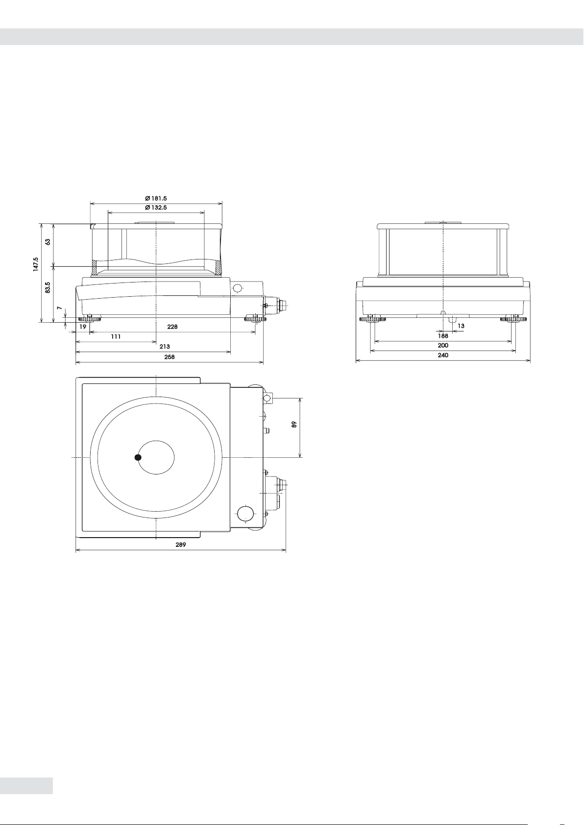
Dimensions
IS6CCE-SX, IS12CCE-SX
All dimensions given in millimeters
16
Operating Instructions IS-X
Page 17

IS16EDE-HX, IS34EDE-HX, IS34EDE-HX, IS64EDE-SX
Dimensions
All dimensions given in millimeters
Operating Instructions IS-X
17
Page 18

Dimensions
All dimensions given in millimeters
EC Verification“ - A Service Offered by Sartorius Intec
Our service technicians authorized to perform the verification of your weighing instruments that are acceptable for legal metrological
verification can inspect and verify the metrological specifications at the place of installation within the Member States of the European Union
and the Signatories of the Agreement on the European Economic Area.
Subsequent Verifications within the European Countries
The validity of the verification will become void in accordance with the national regulations of the country in which the weighing instrument
is used. For information on verification and legal regulations currently applicable in your country, and to obtain names of the persons to
contact, please contact your local Sartorius Intec office, dealer or service center.
18
Operating Instructions IS-X
Page 19

Certificates
Operating Instructions IS-X
19
Page 20

Certificates
20
Operating Instructions IS-X
Page 21

Certificates
Operating Instructions IS-X
21
Page 22

Certificates
22
Operating Instructions IS-X
Page 23

Type of weighing instrument: iso-TEST Types of weighing modules: BD BF, BF BF, HA BD, HC BF
EC Type-approval D97-09-018 + Test certificates D09-96.30, D09-95.18
or
Type of weighing instrument: SARTOCOWAT Types of weighing modules: BD BF, BF BF, HA BD, HC BF
PPIS030511e EC Type-approval T7899 + Test certificates D09-96.30, D09-95.18
S
S
unlocked
locked
locked
unlocked
For variants for use in hazardous areas
Recognizable at a “-XCE“ in the model name
S
Plates and Markings – IS... -.CE + Terminals
Note: Protective seals of the indicating and operator terminal see belonging manuals.
(nur bei Typ SARTOCOWAT)
(only at type SARTOCOWAT)
P
S
K
M
S
P
locked
unlocked
S
Type BD BF
S
M
K
K
M
Type BF BF
K
M
Connects to the terminal no.
alternative
Connects to the terminal no.
(only at type SARTOCOWAT)
Plates and Markings
Operating Instructions IS-X
23
Page 24

Plates and Markings
Type of weighing instrument: iso-TEST Types of weighing modules: BD BF, BF BF, HA BD, HC BF
EC Type-approval D97-09-018 + Test certificates D09-96.30, D09-95.18
or
Type of weighing instrument: SARTOCOWAT Types of weighing modules: BD BF, BF BF, HA BD, HC BF
PPIS030511e EC Type-approval T7899 + Test certificates D09-96.30, D09-95.18
unlocked
S
S
S
SSS
locked
For variants for use in hazardous areas
Recognizable at a “-XCE“ in the model name
unlocked
locked
(only at type SARTOCOWAT)
(only at type SARTOCOWAT)
K
Descriptive plate with CE-conformity mark
M
Mark for EC verification (green metrology sticker)
S Protective seal
T
Plate with model designation
P
Menu access switch
S
S
S
Type HA BD
Connects to the terminal no.
S
K
M
Type HC BF
weighing pan
Connects to the terminal no.
M
K
T
locked
T
unlocked
P
P
24
Operating Instructions IS-X
Page 25

In connection with Terminals types TN CIS2, CISL2, CIS3 or computer (CE) and
software Win Dcale (Do9-99.15)
Plates and Markings
Example of descriptive of the already veried weighing instrument
Example o plate with model designation - weighing module
IS64FEG-S0CE
IS64FEG-S0CE
Example o plate with model designation - terminal
In connection with Terminals types TA (CAIS1, CAISL1, CAIS2, CAISL2, CAIS3, CAISL3
Example of descriptive of the already veried weighing instrument
T
K
T
K
Example o plate with model designation - weighing module
IS6CCE-H0CE
IS6CCE-H0CE
Example o plate with model designation - terminal
CAIS3
CAIS3
Type of weighing instrument: isi-Test types of modules: BD BF, BF BF, HC BF,
HA BD, HC BF, EC Type-approval D97-09-18 + Prüfschein DO9-95-18
oder
Type of
weighing instrument: SARTOCOWAT types of modules BD BF, BF BF, HC
BF, HA BD, EC Type-approval T7899 + Prüfschein DO9-96-30, Do9-95-18
PPIS030511e/3
T
T
Operating Instructions IS-X
25
Page 26

Certicate
26
Operating Instructions IS-X
Page 27

Certificate
Operating Instructions IS-X
27
Page 28

Certificate
28
Operating Instructions IS-X
Page 29

Certificate
Operating Instructions IS-X
29
Page 30

Certificate
30
Operating Instructions IS-X
Page 31

Certificate
Operating Instructions IS-X
31
Page 32

Certificate
32
Operating Instructions IS-X
Page 33

Certificate
Operating Instructions IS-X
33
Page 34

Certificate
34
Operating Instructions IS-X
Page 35

Certificate
Operating Instructions IS-X
35
Page 36

Certificate
36
Operating Instructions IS-X
Page 37

Certificate
Operating Instructions IS-X
37
Page 38

Certificate
38
Operating Instructions IS-X
Page 39

Certificate
Operating Instructions IS-X
39
Page 40

Certificate
40
Operating Instructions IS-X
Page 41

Circuit: V1 V2 V3 V4
Li 0000
Uo 12.6 V 12.6 V 8.6 V 12.6V
Io 133 mA 133 mA 187 mA 150 mA
Po 1.46 W 1.46 W 1.51 W 1.68 W
Co 1µF 1µF 4 µF 1 µF
Lo 300µH 300 µH 300 µH 300 µH
Power supply
YPS02-Z.R
II (2) G
[EEx ib] IIC
II (1) D
Certificate
Non hazardous area
Sartorius cable: type LiYC-Y-CY 4 x 0,5²
(permanently installed on power supply; can be
Power supply
YPS02-X.R
II 2 G
Alternative
Connection
flexibly installed)
max. Length = 50 m
max. L
max. C
EEx d [ib] IIC T4
II 1 D T135°C
Circuit: V1 V2 V3 V4
Uo 12.6 V 12.6 V 8.6 V 12.6V
Io 133 mA 133 m A 187 mA 150 m A
Po 1.46 W 1.46 W 1.51 W 1.68 W
Co 1µF 1µF 4 µF 1 µF
Lo 300µH 300 µH 300 µH 300 µH
Barrier
YDI02-Z
YDI03-Z
II (2) G
[EEx ib] IIC
Circuit: RS-232
Uo 12 V 12 V
Io 82 mA 7.5 mA
Po 240 mW 22 m W
Co 1.41 µF 1.41 µF
Lo 5.5 mH 5.5 mH
Lo/Ro 144µH/ 1.5 mH/
= 8.4 µH
Cable
= 28.2 nF
Cable
Date
EX
12.02.02
Written by
Reviewed by
Released by
1)
12.02.02
12.02.02
Control signals (only for YDI03-Z)
Name
Klausgrete
Weitemeier
Klausgrete
IIC T4
Hazardous area
Compact scale
FC......-.X....
FCA......-.X....
Weighing platform
IS......-.X....
II 2 G EEx ib IIC T4
II 1 D T135°C (optional)
Circuit: V1 V2 V3 V4
Ui 12.6 V 12.6 V 8.6 V 12.6V
Ii 133 mA 133 mA 187 m A 150 mA
Pi 1.68 W 1.68 W 1.61 W 1.89 W
Ci 0 0 300 nF 100 nF
FC/FCA/IS......-.X.... /
1)
Power Supply
Verification of the
Intrinsic Safety
35520-099-61-A4
Sheet
Rev.
1
of
4
00
Non hazardous area
Cable: install as stationary
and protect ed equipment !
Maximum cable length 70m
for a 10-wire standard cable
with a maximum of 200 nF/
km and 1mH/k m.
The length of the installed
cable is defined as 20 m
because of the RS-232
specifications.
System appraisal
(see EC-Type Examination Certificate KEMA 02ATEX1108 X):
Co <= 125nF; Lo <= 100µH; Lo/Ro <= 33µH/
Data output
Uo 8,6 V
Io 23 mA
Po 50 mW
Co 6 µF
Lo 60 mH
Data output RS-232 Control signals
Ui 12.6 V 12.6V
Ii 85 mA 10 mA
Pi 270 mW 30 mW
Ci 3 nF 4 nF
Li 0 0
1)
(pins A/J/K/N and M)
EX
Written by
Reviewed by
Released by
1)
(pins C/D/E/F/G and M)
Name
Date
Klausgrete
12.02.02
Weitemeier
12.02.02
Klausgrete
12.02.02
IIC T4
T-connektor
YTE02-X
1)
actuated
switch
YPE05-X
1: per circuit
2: optionally used (passive wiring or switch only)
FC/FCA/IS......-.X.... /
2)
Foot
2)
RS-232 data output with control lines
II 2 G EEx ib IIC T4
II 1 D T135°C (optional)
Verification of the
Intrinsic Safety
35520-099-61-A4
Operating Instructions IS-X
Hazardous area
Compact scale
FC......-.X....
FCA......-.X....
Weighing platform
IS......-.X....
Sheet
Rev.
2
of
4
00
41
Page 42

Certificate
Barrier
YDI01-Z
II (2) G
[EEx ib] IIC
RS-485
Uo 12 V
Io 82 mA
Po 240 mW
Co 1.41 µF
Lo 5,5 mH
1)
Barrier
YDI03-Z
II (2) G
[EEx ib] IIC
Only control signals
(see sheet 2)
Non hazardous area
up to 7 f urther
units, which
have the same
type of RS-485
data output
connected to
this fieldbus
Cable: install as stationary and protected equipment !
For cables with a maximum of 125pF/m (wire versus wire):
Number of units Cable length Lo/Ro or Lo
in the hazardous area m µH/ µH/km
2 1000 61 400
4 1000 34 115
6 1000 22 46
8 1000 17 25
8 100 17 250
8 35 17 710
see also table in KEMA 02ATEX1108X, sheet 3/4
Converter
Data output RS-485 only (pins J/K)
Ui 12,6 V
Ii 810 mA
Pi 2.5 W
Ci 10 nF
Li 0
Uo 12.6V
Io 85 mA
Po 270mW
In accordance with the EC-T ype Examination Certificate
KEMA 01ATEX1099X the converter 725324 m ay be
connected to the FCT01-X.., but with reduced param eters:
Co = 620nF
Lo=2mH.
725324
[EEx ib] IIB
2)
Cable: install as stationary
and protected equipment !
Maximum cable length 70m
for a 10-wire s tandard cable
with a maximum of 200nF/
km and 1mH/k m.
IIC T4
Date
EX
12.02.02
Written by
Reviewed by
Released by
12.02.02
12.02.02
Name
Klausgrete
Weitemeier
Klausgrete
Data output;
only control signals
(see sheet 2)
T-connektor
YTE02-X
T-connektor
YTE02-X
Foot
actuated
3)
switch
YPE05-X
FC/FCA/IS......-.X.... /
Hazardous ar ea
Compact scale
3)
FC......-.X....
FCA......-.X....
Weighing platform
IS......-.X....
3)
II 2 G EEx ib IIC T4
II 1 D T135°C (optional)
1: per circuit
2: circuits combined
3: optionally used (passive wiring or switch only)
RS-485 data output and control signal outputs
Verification of the
Intrinsic Safety
35520-099-61-A4
Sheet
of
Rev.
3
4
00
42
Cable: install as stationary and
protected equipment. Maximum
length 600m for a standard
cable with a m aximum of
200nF/km and 1mH/k m.
Operating Instructions IS-X
IIC T4
TTY Data output
Ui 14.7 V 14.7 V
Ii 50 mA 130 mA (resistively limited)
Pi 265 mW 100 mW
Ci 0 0
Li 0 0
1: per circuit
1)
(pins G/K and D/F/J) (pins C/E and D/F/J)
Name
Date
EX
Written by
Reviewed by
Released by
12.02.02
12.02.02
12.02.02
Klausgrete
Weitemeier
Klausgrete
FC/FCA/IS......-.X.... /
10mA data output
Non hazardous area
Hazardous ar ea
Compact scale
FC......-.X....
FCA......-.X....
Weighing platform
IS......-.X....
II 2 G EEx ib IIC T4
II 1 D T135°C (optional)
Verification of the
Intrinsic Safety
35520-099-61-A4
Sheet
of
Rev.
4
4
00
Page 43

Certificate
Hazardous (Classified) Location
Class I, Division 1, Groups A,B,C,D
Class I, Zone 1, Groups IIA, IIB, IIC
SARTORIUS
FC......-.X...
Display Unit
4)
SARTORIUS
FC...BBE-.X.... or
IS...BBE-.X.... or
10)
FC...CCE-.X.... or
IS...CCE-.X....
.....EDE-.X....
+)
Weighing Module
Data Output
3)
5)
4)
SARTORIUS
Pedal Switch
YPE05-X
9)
SARTORIUS
T-Connector
YTE02-X
4)
SARTORIUS
Pedal Switch
YPE05-X
9)
SARTORIUS
T-Connector
YTE02-X
Hazardous (Classified) Location
Class I,II,III, Division 1,
Groups A,B,C,D,E,F,G
13)
SARTORIUS
Power Supply
YPS02-XKR
3)
7)
AC Supply
Canada: Group A is excluded!
OR
13)
SARTORIUS
Rechargeable
Battery Pack
YRB02-X
see
Control drawing
65656-001-07
Non-Hazardous Location
3)
9)
13)
9)
6)
SARTORIUS
Power Supply
YPS02-ZKR
AC Supply
Hazardous (Classified) or
Non-Hazardous Location
Any Approved / Certified
Universal Apparatus with
Entity Concept
parameters
YDI05-Z..
e.g.
(see note 5, 15)
7)
3)
2)
+: All FC..EDE-.X.., FCA..EDE-.X.., IS..EDE-.X..
with lower IP rating than IP65; see marking on the equipment !
Date
Written by
Reviewed by
Released by
2011-07-07
2011-07-07
2011-07-07
Name
Klausgrete
Klausgrete
Klausgrete
Title
Drawing
number
Control Drawing
33956-000-07-A4
Revision
04
Sheet
1
Operating Instructions IS-X
of
5
43
Page 44

Certificate
Hazardous (Classified) Location
Class I,II,III, Division 1, Groups A,B,C,D,E,F,G
Class I, Zone 1, Groups IIA, IIB, IIC
SARTORIUS
FC......-.X...
Display Unit
4)
SARTORIUS
FC...EDE-.X.... or
10)
IS...EDE-.X.... or
IS...IGG-.X....
3)
Weighing Module
Data Output
5)
4)
SARTORIUS
Pedal Switch
YPE05-X
9)
SARTORIUS
T-Connector
YTE02-X
4)
SARTORIUS
Pedal Switch
YPE05-X
9)
SARTORIUS
T-Connector
YTE02-X
Hazardous (Classified) Location
Class I,II,III, Division 1,
Groups A,B,C,D,E,F,G
13)
SARTORIUS
Power Supply
YPS02-XKR
3)
7)
AC Supply
Canada: Group A is excluded!
OR
13)
SARTORIUS
Rechargeable
Battery Pack
YRB02-X
see
Control drawing
65656-001-07
Non-Hazardous Location
9)
13)
SARTORIUS
Power Supply
YPS02-ZKR
9)
Hazardous (Classified) or
Non-Hazardous Location
3)
7)
AC Supply
44
Written by
Reviewed by
Released by
Operating Instructions IS-X
Date
2011-07-07
2011-07-07
2011-07-07
Name
Klausgrete
Klausgrete
Klausgrete
Title
Drawing
number
6)
Control Drawing
33956-000-07-A4
Any Approved / Certified
Universal Apparatus with
Entity Concept
parameters
YDI05-Z..
e.g.
(see note 5, 15)
Revision
04
Sheet
3)
2)
of
2
5
Page 45

Hazardous (Classified) Location
Class I,II,III, Division 1, Groups A,B,C,D,E,F,G
Class I, Zone 1, Groups IIA, IIB, IIC
SARTORIUS
FCA...EDE-.X....or
FCB...EDE-.X....or
3)
FCA...IGG-.X....
or
FCB...IGG-.X....
Weighing Module
Terminal YAC01FC-X or
Terminal YAC02FC-X or
Junction Box YAS06IS-X
Data Output (only for YAC0*FC-X)
4)
SARTORIUS
10)
3)
5)
+
OR
Hazardous (Classified) Location
Class I,II,III, Division 1,
Groups A,B,C,D,E,F,G
13)
SARTORIUS
Power Supply
YPS02-XKR
Canada: Group A is excluded!
13)
SARTORIUS
Rechargeable
Battery Pack
YRB02-X
Certificate
3)
7)
AC Supply
see
Control drawing
65656-001-07
I/O-Ports (only for YAC02FC-X)
14)
SARTORIUS
Pedal Switch
YPE05-X
SARTORIUS
Pedal Switch
YPE05-X
+: Only on Model YAC0*FC-X
Non-Hazardous Location
4)
9)
SARTORIUS
T-Connector
YTE02-X
9)
13)
SARTORIUS
Power Supply
YPS02-ZKR
3)
7)
AC Supply
4)
9)
SARTORIUS
T-Connector
YTE02-X
OR
9)
6)
Hazardous (Classified) or
Non-Hazardous Location
Any FApproved / Certified
Universal Apparatus with
Entity Concept
parameters
YDI05-Z..
e.g.
(see note 5, 15)
3)
2)
Date
Written by
Reviewed by
Released by
2011-07-07
2011-07-07
2011-07-07
Name
Klausgrete
Klausgrete
Klausgrete
Title
Drawing
number
Control Drawing
33956-000-07-A4
Revision
04
Sheet
3
Operating Instructions IS-X
of
5
45
Page 46

Certificate
ENTITY DATA FOR TERMINAL:
Data Output (Pos. 5) Input Parameters :
RS232 (combined circuits):
(Pin A/J/K/N/M): Ui = 12.6 V Ii = 340 mA * Pi = 1.08 W Ci = 2 nF Li = 15 µH
Ui = 25,2 V **
RS422 (combined circuits):
(Pin A/B/C/E/F/G/J/K/M/N): Ui = 7.5 V Ii = 500 mA * Pi = 900 mW Ci = 5.5 µF Li = 17 µH
RS485 (combined circuits):
(Pin J/K/L/M): Ui = 12.6 V Ii = 810 mA * Pi = 2.5 W Ci = 12 nF Li = 15 µH
Control Signals on RS232 or RS485 (per circuit):
(Pin C/D/E/F/G/M): Ui = 12.6 V Ii = 10 mA Pi = 30 mW Ci = 4 nF Li = 0
(Pin B/O) only for use in combination with simple apparatus: Ci = 4 nF Li = 0
TTY (Pin G/K andD/F/J): Ui = 14.7 V Ii = 50 mA Pi = 265 mW Ci = 2 nF Li = 15 µH
(Pin C/E and D/F/J): Ui = 14.7 V Ii = 130 mA Pi = 100 mW
Ci = 2 nFLi = 15 µH
The circuits may be connected to the converter Type 725324-1: Co = 620nF
Lo = 2mH
Data Output (Pos. 5) Output Parameters (combined circuits):
RS232 (combined circuits):
(Pin A/J/K/N/M): Uo = 12.6 V Io = 131 mA * Po = 411 mW Co = 1.15 µF Lo = 2 mH
RS422 (combined circuits):
(Pin A/B/C/E/F/G/J/K/M/N): Uo = 12.6 V Io = 180 mA * Po = 570 mW Co = 1.15 µF Lo = 0.7 mH
Lo/Ro = 62 µH/ohm
RS485 (combined circuits):
(Pin J/K/L/M): Uo = 12.6 V Io = 85 mA * Po = 270 mW Co = 1.15 µF Lo = 5 mH
Lo/Ro = 118 µH/ohm
Maximum length for a typical standard data cable:
RS232 limited by the RS232 standard to 25m ( 82 feet)
RS422 500 m (1,640 feet) for Group A,B,C,D and IIA, IIB, IIC; 1000 m (3,280 feet) for Group C, D and IIA, IIB
TTY 300 m (984 feet) for 1,200 bit/s; 150 m (492 feet) for 2,400 bit/s; 65 m (213 feet) for 4,800 bit/s;
30 m (98 feet) for 8,600 bit/s; 15 m (49 feet) for 19,200 bit/s; for Group A,B,C,D and IIA, IIB, IIC
RS485 up to 1000 m (3,280 feet)
with up to 8 Sartorius scales type FC/FCA/IS......-.X... or CIXS3-. or WZ......-X.. CW3X..-.... or FCT01-X..
when connected to Sartorius Interface Converter YDI05-Z.. or Barrier YDI01-Z.. or YDI02-Z..
the Barriers YDI0.-Z.. contain Z966 zener barriers from Pepperl & Fuchs.
Uo = 25,2 V ** Co = 107 nF **
46
Written by
Reviewed by
Released by
Operating Instructions IS-X
Date
2011-07-07
2011-07-07
2011-07-07
Name
Klausgrete
Klausgrete
Klausgrete
Title
Drawing
number
Control Drawing
33956-000-07-A4
Revision
04
Sheet
of
4
5
Page 47

1) In the USA: The installation must be in accordance with the National Electrical Code ®, NFPA 70, Article 504 or 505
and ANSI / ISA-RP 12.6.
In Canada: The installation must be in accordance with the Canadian Electrical Code ®, Part1, Section 18.
2) The apparatus must not be connected to any device that uses or generates in excess of 250Vrms or DC.
3) In the USA: The apparatus must be connected to a suitable ground electrode per National Electrical Code ®, NFPA
70, Article 504 or 505. The resistance of the ground pad must be less than 1 ohm.
In Canada: The apparatus must be connected to a suitable ground electrode per Canadian Electrical Code ®, Part
1. The resistance of the ground pad must be less than 1 ohm.
4) The cable to the terminal model YAC01LA-X00FC and to the T-Connector model YTE02-X must be protected
against damage.
5) The Entity Concept allows interconnection of intrinsically safe apparatus with associated apparatus not
specifically examined in combination as a system when the approved values of Voc, Isc and Pmax resp. Uo, Io, Po
of the associated apparatus are less than or equal to Vmax, Imax and Pmax resp. Ui, Ii, Pi of the intrinsically safe
apparatus and the approved values of Ca and La resp. Co and Lo of the associated apparatus are greater than Ci
and Li of the intrinsically safe apparatus plus all cable parameters.
6) In the USA: Optionally, the cable of any FMRC Approved Universal Apparatus with Entity Concept parameters (see
note 5) can be connected directly to the data output of the weighing module; this cable must be protected against
damage.
In Canada: Optionally, the cable of any CSA Certified Universal Apparatus with Entity Concept parameters (see
note 5) can be connected directly to the data output of the weighing module; this cable must be protected against
damage.
7) The apparatus must not be connected to any device that uses or generates in excess of 132Vrms or DC.
8) The cable to the terminal model YAC01FC-X or model YAC02FC-X needs not be protected against damage.
9) In the USA: These units are considered as non-certified simple apparatus. The levels as indicated for simple
apparatus in FMRC Class 3610 shall not be exceeded in this simple apparatus.
In Canada: These units are considered as non-certified simple apparatus. The temperature class of the apparatus
has to be determined. Per Levels generated in the simple apparatus as indicated in Table 3 of CAN/CSA-E79-11-
95.
When the parameters of the apparatus are not specified, based on the entity parameters of the weighing module
output the temperature class has to be determined and the capacitance and inductance of the interconnecting cable
may not exceed the Co and the Lo.
10) Connection by means of polarized connector.
11) Ambient temperature range: 0°C .... +40°C (32°F .... + 104°F)
12) WARNING: SUBSTITUTION OF COMPONENTS MAY IMPAIR INTRINSIC SAFETY.
AVERTISSEMENT: LA SUBSTITUTION DE COMPOSANTS PEUT COMPROMETTRE LA
SÉCURITÉ INTRINSÈQUE.
13) Connection by non interchangeable cable type LiYC-Y-CY 4 x 0.5; max length: 50m (164 ft).
14) The Entity Concept allows interconnection of intrinsically safe apparatus with associated apparatus not
specifically examined in combination as a system when the approved values of Voc, Isc and Pmax resp. Uo, Io, Po
of the associated apparatus are less than or equal to Vmax, Imax and Pmax resp. Ui, Ii, Pi of the intrinsically safe
apparatus and the approved values of Ca and La resp. Co and Lo of the associated apparatus are greater than Ci
and Li of the intrinsically safe apparatus plus all cable parameters.
The output circuits of the optional I/O of Type FCB must be connected to grounded shunt diode barriers; this ground
to be connected with the P.E. within the hazardous area.
15) The Sartorius Interface Converter YDI05-Z.. is approved/certified by FM for USA and Canada. See Certificate of
Compliance and Control Drawing number 65710-800-07-A4.
Furthermore Sartorius Barriers YDI01-Z.. and YDI02-Z.. may be used, which contain FM and CSA approved /
certified Z966 zener barriers from Pepperl & Fuchs.
16) WARNING: USE WET OR DAMP CLOTH TO CLEAN TO AVOID ELECTRIC STATIC DISCHARGE.
Certificate
Date
Written by
Reviewed by
Released by
2011-07-07
2011-07-07
2011-07-07
Name
Klausgrete
Klausgrete
Klausgrete
Title
Drawing
number
Control Drawing
33956-000-07-A4
Revision
04
Sheet
5
Operating Instructions IS-X
of
5
47
Page 48

Sartorius Industrial Scales GmbH & Co. KG
Leinetal 2
37120 Bovenden, Germany
Phone +49.551.309.83.0
Fax +49.551.309.83.190
www.sartorius-intec.com
Copyright by Sartorius Intec,
Goettingen, Germany.
No part of this publication may be reprinted or
translated in any form or by any means without
prior written permission from Sartorius Intec.
All rights reserved.
The status of the information, specifications
and illustrations in this manual is indicated
by the date given below. Sartorius Intec
reserves the right to make changes to the
technology, features, specifications, and design
of the equipment without notice.
Date:
April 2016, Sartorius Intec
Bovenden, Germany
Printed in Germany on paper that has been
bleached without any use of chlorine
RS ·KT
Publication No.:WIS6019-e16042
 Loading...