

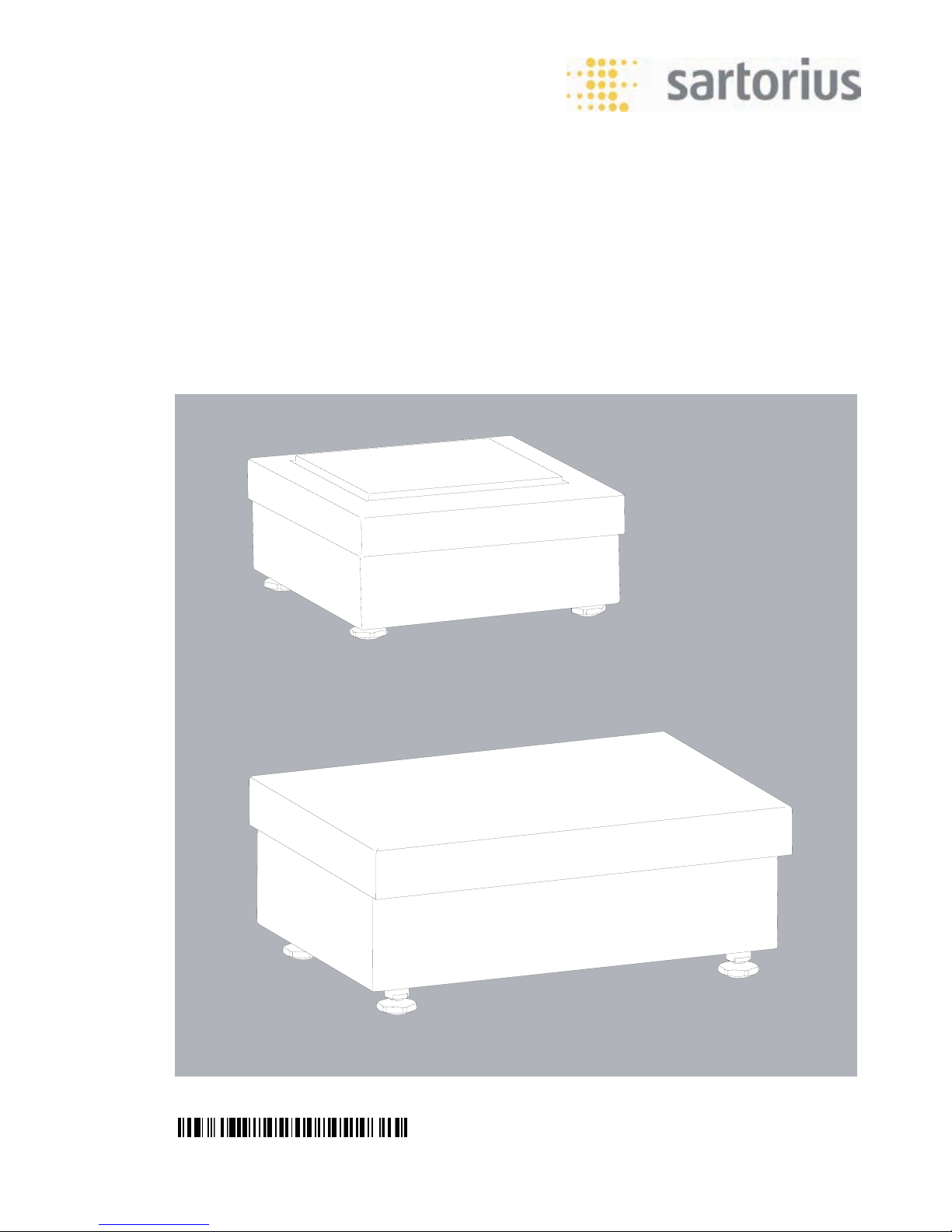
Operating Instructions
Sartorius ISBBS, ISDCS
Weighing Platform
98648-019-05

2
ISBBS, ISDCS Operating Instructions
Table of Contents
Table of Contents
Copyright .............................................................................3
Intended Use ........................................................................ 3
Warnings and Safety Precautions ....................................4
Getting Started ................................................................... 5
Installation Instructions ..................................................... 6
Leveling the Weighing Platform ...................................6
Ground Conductor ........................................................... 6
Data Interface .....................................................................7
Pin Assignment ................................................................7
Menu Access Switch ........................................................... 8
Specifications ......................................................................9
ISBBS Weighing Data .......................................................10
ISDCS Weighing Data .......................................................11
Error Messages ..................................................................12
Care and Maintenance .....................................................13
Cleaning Stainless Steel Surfaces ...............................14
Disposal ..............................................................................15
Potentially Explosive Atmosphere ..................................16
Dimensions (Scale Drawings)...........................................18

ISBBS, ISDCS Operating Instructions
3
Legal Terms and Conditions
Copyright
This documentation may not be reproduced or distributed either in whole or in
part without the explicit written permission of Sartorius.
This documentation is intended only for use by the buyer.
Transfer to third parties, whether free or in exchange for payment, is not
permitted.
The software is the property of Sartorius. The software may not be copied or
modified; it may not be decompiled or modified through assimilation.
The buyer may only use the software for his own purposes and may not make
the software available to third parties for use either for free or in exchange for
payment. If you encounter problems with the included software, please contact
the software distributor. Sartorius reserves the right to deliver updated software
for this product.
No liability is accepted for software installed before the purchase of this product.
The buyer is liable for any misuse of the product.
Intended Use
As precise and robust weighing platforms, the ISBBS and ISDCS provide
reliable weighing results. The models are based on monolithic
technology (the principle of electromagnetic force compensation).
These industrial weighing platforms offer the following special features:
– Robust and durable Sartorius quality
– IP65 protection from dust and jets of water
– High-quality workmanship and materials
– Preload values can be defined (for equipment installed on the scale)
4
ISBBS, ISDCS Operating Instructions
Safety Precautions
Warnings and Safety Precautions
3 Read these operating instructions thoroughly before using the weighing
platform, in order to prevent damage to the equipment.
3 The weighing platforms comply with the European Council Directives as well as
international regulations and standards for electrical equipment, electromagnetic
compatibility, and the stipulated safety requirements.
3 Do not expose the equipment to aggressive chemical vapors or to unnecessarily
extreme temperatures, moisture, shocks, or vibration.
2 Avoid generating static electricity and connect equipotential bonding terminals.
3 All models meet the criteria for protection class IP65.
Any installation work that does not conform to the instructions in this manual
results in forfeiture of all claims under the manufacturer’s warranty.
3 If there is any indication that safe operation of the equipment is no longer
guaranteed, disconnect the platform from the power and ensure that it is not
used further.
3 Always ensure that the weighing platform is disconnected from AC power before
performing any maintenance, cleaning, or repair work.
3 Note the pin assignments when using cables provided by other manufacturers.
Check the connections of the cable against the corresponding cabling diagram
before connecting to the Sartorius equipment and disconnect any wires that are
assigned differently. The operator shall be solely responsible when using cables
not supplied by Sartorius.
3 The weight value can be affected by extreme electromagnetic influences.
Once the disturbance has ceased, the instrument can be used again in
accordance with its intended purpose.
ISBBS, ISDCS Operating Instructions
5
Getting Started
Getting Started
Warning:
3 Unpacked devices can lose their precision if subject to extreme vibrations.
Excessive vibrations may compromise the safety of the equipment. Do not
expose the equipment to unnecessarily extreme temperatures, moisture,
shocks, or vibrations.
Permitted storage temperature: -10°C to +40°C
Unpacking the Equipment
Remove the device from the packaging. Check for any visible damage. Save the
original packaging for any future transport. Unplug all connected cables before
packing the equipment.
Acclimatizing the Device
3 The device should only be opened by trained and qualified personnel.
Before opening the valve unit: Turn the main switch to “OFF." Take all steps
necessary to secure the equipment against unauthorized power-up.
Disconnect the device from the power supply if possible.
Once work is completed: Securely lock the valve unit.
Scope of Supply:
– Weighing platform
– Operating instructions
– Special accessories as listed on the bill of delivery, if ordered

6
ISBBS, ISDCS Operating Instructions
Installation Instructions
Installation Instructions
t Set up a suitable installation location for the weighing platform.
The place of installation should be dry, level, and flat. The operating temperature
ranges from -10°C to +40°C.
The weighing platform must not be subjected to unnecessarily extreme
temperatures, moisture, shocks, or vibrations that could result in damage.
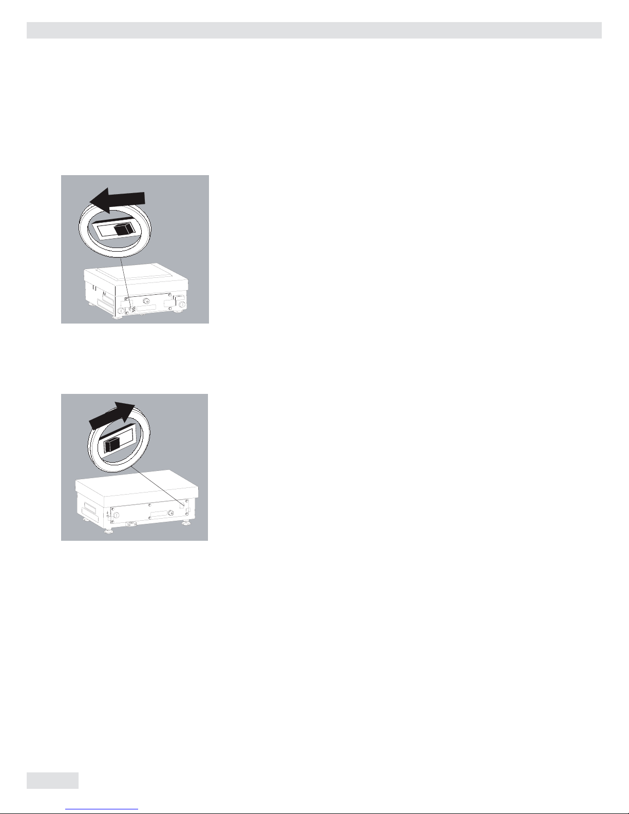
Leveling the Weighing Platform
Purpose: – To compensate for uneven areas at the place of installation
– To ensure that the equipment is placed in a perfectly horizontal
position for consistently reproducible weighing results
Always level the weighing platform again any time after it has been moved to
a different location.
t Level the weighing platform using the four leveling feet. Turn the feet until
the air bubble is centered in the level indicator.
t Check to ensure that all leveling feet rest securely on the work surface.
y Each of the leveling feet must support an equal load.
y Adjusting the leveling feet:
To raise the weighing platform, extend the leveling feet (turn counterclockwise).
To lower the weighing platform, retract the leveling feet (turn clockwise).
Ground Conductor
The ground conductor is located underneath the weighing pan on the clamp
box or on the lower base of the weighing platform. It is marked as a ground
connection with the symbol shown here.
Grounding is implemented using a threaded bolt or screw terminal, or as a hole.
If a ground hole is the method of grounding, a stainless steel screw and nut
must be used. A lock washer should be placed underneath in order to prevent
the screw from loosening. The grounding cable must have a minimum crosssection of 4 mm2 and must be fitted with a suitable ring terminal. Connect
all equipment, including peripheral devices, to the equipotential bonding
conductor.
°C
ISBBS, ISDCS Operating Instructions
7
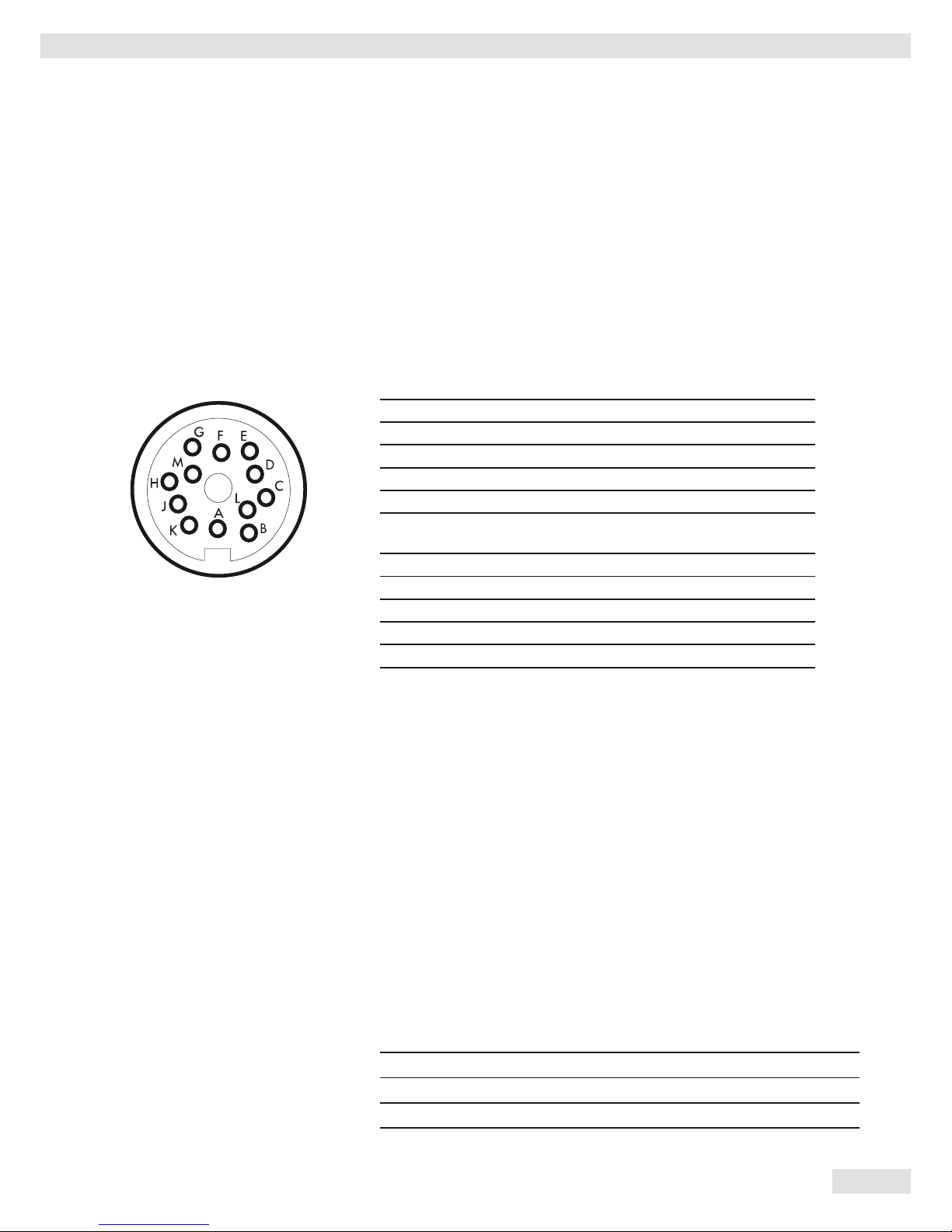
Data Interface
The weighing platform has a standard COM1 interface, RS-485 socket (IP65).
The standard COM1 interface can be converted to RS-232 through the
Sartorius Service Center.
Pin Assignment
COM 1 round plug connector with screw connection.
Front view:
RS-485 data interface RS-232 data interface
A RxD–TxD–N Not used
B Not used RxD
C Not used TxD
D Not used CTS
E GND GND
F Menu access switch
for adjustment
Menu access switch
for adjustment
G 12-30 VDC 2W supply 12-30 VDC 2W supply
H Not used DTR
J GND GND
K GND GND
L RxD–TxD–P Not used
M 12-30 VDC 2W supply 12-30 VDC 2W supply
h Female Interface Connector (Recommended):
Type C091D, 12-pin, Amphenol (IP65) cable type as per AWG 24
Observe power supply instructions.
Operation as an RS485-interface:
Switch 4 must be open in order to switch to RS-485 operation (factory setting).
Where applicable, deactivate bias resistors for RS-485 operation. Open switches
for this purpose (factory setting).There must only be one instance of bias
resistors per transmission path (network orpoint-to-point connection). Otherwise
there is a risk of transmission errors. Where applicable, refer to the specifications
or circuit documentation for the remote station or network nodes in question.
Bias resistors must always be activated or deactivated in pairs. The terminating
resistor (transmitting side, switch 1 must be activated if the device is located at
either end of an RS-485 bus system, or where it is connected to another device
in a point-to-point link. There must also be a terminating resistor of 120 Ω in
place at the remote station. Where applicable, activate terminating resistor 120
Ω for RS-485operation:
Terminating resistor, receiving side 120 Ω Switch 1 on
BIAS resistor, receiving side (RxD+, pull-up) 680 Ω Switch 2 on
BIAS resistor, receiving side (RxD–, pull-down) 680 Ω Switchr 3 on
No function Switch 4
Data Interface
8
ISBBS, ISDCS Operating Instructions
Menu Access Switch
Menu Access Switch
ISBBS
Switch on the right = for use in legal metrology
Switch on the left = external calibration/adjustment accessible
ISDCS
Switch on the right = for use in legal metrology
Switch on the left = external calibration/adjustment accessible

ISBBS, ISDCS Operating Instructions
9
Specifications
Specifications
General Specifications
The CE conformity is only guaranteed when using Sartorius accessories.
Digital protective interface as per EN 45501
Data interface RS-485
Housing: material
Protection class as per EN 60529
stainless steel
IP65
Temperature range –10°C to +40°C
Humidity max. relative humidity is 80% for temperatures up to 31°C
DC supply optional 15.524 V DC (±10%), max. 12 W via interface
Interference emission as per EN 61326+A1, Class B (IEC 61326+A1)
Interference immunity as per EN 61326+A1, industrial areas (IEC 61326+A1)
Electrical safety as per EN 61010-1 (IEC 61010-1), EN 60950 (IEC 60950)

10
ISBBS, ISDCS Operating Instructions
ISBBS Weighing Data
ISBBS Weighing Data
Non-verifiable Models
Weighing capacity (kg) 3.1 6.1
Readability (g) 0.01 0.01
Resolution code -H -H
Calibration weight value
(in grams)
2000 5000
Accuracy class E2 E2
Preload (kg) 3 0
Reproducibility (g) 0.01 0.01
Linearity (g) 0.02 0.02
Ambient temperature -10°C to +40°C

ISBBS, ISDCS Operating Instructions
11
ISDCS Weighing Data
ISDCS Weighing Data
Non-verifiable Models
Weighing capacity (kg) 16 35
Readability (g) 0.1 0.1
Resolution code -H -H
Calibration weight value
(in grams)
10,000 10,000
Accuracy class F1 F1
Preload (kg) 5 5
Reproducibility (g) 0.08 0.08
Linearity (g) 0.02 0.02
Ambient temperature -10°C to +40°C

12
ISBBS, ISDCS Operating Instructions
Error Messages
Error Messages
Error messages are output via the interface. Error messages are shown permanently; information messages are shown for
two seconds. After this the program automatically returns to the weighing mode.
Display Cause Solution
Err 101 Key is stuck when switching on Release key or contact your local Sartorius Service
Center
Err 320 Operating program memory faulty Contact your local Sartorius Service Center
Err 335 Verified weighing platform not compatible with the
connected terminal
Connect a compatible weighing platform
Err 340 Incorrect operating parameter (EEPROM) Turn the scale off and then on again. If the error
code is still displayed: Contact your local Sartorius
Service Center
Err 341 RAM has lost data; battery is dead Leave the scale connected to power for at least 10 hrs
Err 343 Loss of data in memory for transaction numbers in
external Alibi memory
Contact your local Sartorius Service Center
Inf 01 Data output not compatible with output format Set output format correctly
Inf 02 Calibration/adjustment condition not met;
tare or unload the scale
Do not calibrate until 0 display
Inf 03 Adjustment could not be completed within a certain
time
Allow to warm up again and repeat the adjustment
process
Inf 06 Built-in calibration weight defective Contact your local Sartorius Service Center
Inf 07 Function not allowed in scales verified for use in legal
metrology
Contact your local Sartorius Service Center for infor-
mation on changing settings
Inf 08 The load on the scale is too heavy to zero the readout Check whether “Tare/zero at power on” is set in your
configuration
Inf 09 Taring is not possible when the scale gross weight is
< zero
Zero the scale
Inf 10 Tare key is blocked when there is data in the tare
memory
The data stored for the application program must be
deleted before taring
Inf 22 Error in storing reference value,
Weight is too low
Place a heavier weight on the platform
Inf 23 Error in initializing an application Contact your local Sartorius Service Center
Inf 29 Minimum load not reached Define a lower value for the minimum load
Inf 71 Cannot store the current weight value
(e.g., control limits too low or too high)
None
Inf 72 Cannot store the current weight value
(e.g., transaction counter maximum reached)
None
Inf 73
Data not found or unreadable Contact your local Sartorius Service Center
Inf 74
Function is blocked (e.g., menu is locked) None
Inf 98
No weighing platform connected Contact your local Sartorius Service Center
Inf 99
No weighing platform connected Contact your local Sartorius Service Center
NO WP
No weighing platform connected Contact your local Sartorius Service Center
Flashing 3Battery defective or time changed Set the time

ISBBS, ISDCS Operating Instructions
13
Care and Maintenance
Care and Maintenance
Cleaning Instructions
t Disconnect the weighing platform from the power supply before cleaning.
t If the scale is located in a dry room, wipe the weighing platform with a moist
cloth. Conventional household cleaning agents can be used. Observe the
manufacturer’s information.
3 Never use concentrated acids, alkali solutions, solvents, or pure alcohol to
clean the equipment.
t If the scale is located in a wet room, clean the weighing platform from above
with a weak water jet (max. 60°C).
3 Using a high pressure cleaner to clean the weighing platform is not
permitted.
Cleaning the Weighing Platform Interior
3 t Use compressed air to clean out the interior or use a weak water jet
(max. 60°C). Take special care to ensure that no dirt gets into the gap.
t Condensation may occur in the device due to the temperature difference if
3 the equipment is cleaned with water that is too hot or cold. Condensation
may cause the equipment to malfunction.

14
ISBBS, ISDCS Operating Instructions
Care and Maintenance
Cleaning the Stainless Steel Surfaces
All stainless steel parts should be cleaned at regular intervals.
Use a damp cloth or sponge to clean stainless steel parts on the scale.
Conventional household cleaning agents which are suitable for stainless steel
are safe for use.
Stainless steel should be cleaned simply by rubbing.
Then clean the weighing platform thoroughly, making sure to remove all
residues. After this, let the device dry. For additional protection, protective oil
may be applied.
3 Do not clean stainless steel parts with any cleaning agents containing sodium
hydroxide, acetic acid, hydrochloric acid, sulfuric acid, or citric acid.
Do not use steel wool scouring pads.
3 Remove all traces of corrosive substances from the scale on a regular basis.

ISBBS, ISDCS Operating Instructions
15
Disposal
Disposal
If the packaging is no longer needed, it can be disposed of by local waste
disposal authorities. The packaging is made of environmentally friendly
materials that can be used as secondary raw materials. The equipment, including
accessories and batteries, should not be disposed of as regular household waste.
EU legislation requires its Member States to collect electrical and electronic
equipment and dispose of it separately from other unsorted municipal waste so
that it may be recycled. In Germany and several other countries, Sartorius itself
assumes responsibility for the return and conformant disposal of its electronic
and electrical products. These products may not be placed with household waste
or brought to collection centers run by local public disposal operations – not
even by small commercial operators. For disposal in Germany and in the other
member nations of the European Economic Area (EEA), please contact our local
service technicians or our Service Center in Goettingen, Germany:
Sartorius Service Center
Weender Landstrasse 94–108
37075 Goettingen, Germany
SWT GÖ: WEEE-Reg.-Nr. DE 49923090
In countries that are not members of the European Economic Area (EEA) or
where no Sartorius subsidiaries or dealerships are located, please contact your
local authorities or a commercial disposal operator. Prior to disposal and/or
scrapping of the equipment, any batteries should be removed and disposed of in
local collection boxes. Sartorius will not take back equipment contaminated with
hazardous materials (ABC contamination) either for repair or disposal. Please
refer to our website (www.sartorius-mechatronics.com) or contact the Sartorius
Service Center for more detailed information regarding repair service addresses or
the disposal of your device.

16
ISBBS, ISDCS Operating Instructions
Option Y2
Potentially Explosive Atmosphere
For devices with option Y2 only: Directive 94/9/EC, “Equipment and protective
systems intended for use in potentially explosive atmospheres"
Applicable European standards:
EN 60079-0 General requirements
EN 60079-15 Equipment protection by type of protection “n”
EN 60079-31 Explosive atmospheres
Equipment dust ignition protection by enclosure “t"

ISBBS, ISDCS Operating Instructions
17
EC Declration of Conformity

18
ISBBS, ISDCS Operating Instructions
Dimensions
Dimensions (Scale Drawings)
ISBBS
250
205
244
182
122,7
106,4
41,9
+20
182
215
269
30

ISBBS, ISDCS Operating Instructions
19
Dimensions
ISDCS
370
304
360
149,05
125,25
42
+20
260
192
258,1

20
ISBBS, ISDCS Operating Instructions
Manufacturer‘s Certicate

ISBBS, ISDCS Operating Instructions
21

22
ISBBS, ISDCS Operating Instructions

ISBBS, ISDCS Operating Instructions
23

Sartorius Weighing Technology GmbH
Weender Landstrasse 94–108
37075 Goettingen
Germany
Phone +49 (0)551.308.0
Fax +49 (0)551.308.3289
www.sartorius-mechatronics.com
Copyright by Sartorius,
Goettingen, Federal Republic of Germany.
No part of this publication may be reprinted or
translated in any form or by any means without
the prior written permission of Sartorius Weighing
Technology GmbH.
All rights reserved by Sartorius in accordance
with copyright laws. The information and figures
contained in these instructions correspond to the
version date specified below. Sartorius reserves the
right to make changes to the technology, features,
specifications, and design of the equipment
without notice.
Version:
April 2013,
Sartorius Weighing Technology GmbH
Goettingen, Germany
Specifications subject to change without notice. ·
KT · RS
Publication No.: WIS6022-e13044
 Loading...