

Sartorius IS 150 IGG-H,IS 300 IGG-H,IS 300 IGG-H0CE,IS 150 IGG-H0CE,IS 150 IGG-H Installation And Operating Instructions Manual
Installation and Operating Instructions
Sartorius
IS 150 IGG-H , IS 150 IGG-H0CE,
IS 300 IGG-H , IS 300 IGG-H0CE
Weighing Platforms
98648-006-06
98648-006-05
Sartorius
IS 150 IGG-H , IS 150 IGG-H0CE,
IS 300 IGG-H , IS 300 IGG-H0CE
Wägeplattformen
Aufstellungs- und Betriebsanleitung

2
Installation Instructions
Contents
General Specifications .................................... 21
ID Label ............................................................. 22
Pin Assignment Chart RS-485 ....................... 23
Troubleshooting Guide .................................... 24
Care and Maintenance .................................... 25
Servicing ......................................................... 25
Cleaning ......................................................... 25
Safety Inspection .......................................... 26
Information on Recycling ............................ 26
TÜV Certificates ............................................... 27
Installation instructions .................................. 31
Legal Measuring Instrument .......................... 34
Preload .............................................................. 35
Approved Auxiliary Measuring Devices......... 36
Certificate ......................................................... 37
Declarations of Conformity ............................ 39
Plates and Markings ........................................ 42
A Service Offered by Sartoriusr ..................... 45
Accessories (Options) ...................................... 46
Certificate ......................................................... 51
Contents
General View of the Weighing Platform .........3
Notes .....................................................................4
Safety Instructions..............................................5
Installation Instructions .....................................6
Getting Started ...................................................7
Unpacking the Weighing Platform ................7
Removing the Transport Locking Devices .....7
Leveling the Weighing Platform ....................8
Connecting the Weighing Platform ..............9
Safety Precautions ........................................ 11
Warm-up Time .............................................. 12
Operating Limits ........................................... 12
Shock Resistance ........................................... 12
General Instructions ....................................... 13
Preload Range (Zero-Setting Range) ......... 13
Dimensions ........................................................ 14
Pit Installation of the Weighing Platform ... 15
Installation of the Drive-on Ramp YAR ........ 17
Configuring the Weighing Platform ............. 18
Specifications Chart ........................................ 19
Installation Instructions
3
General View
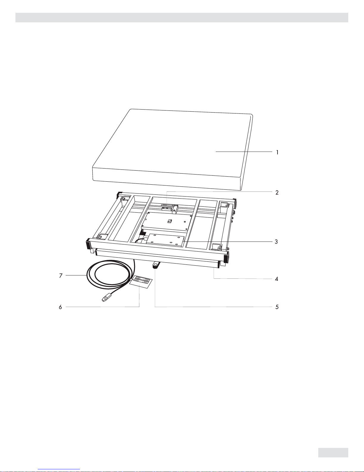
General View of the Weighing Platform
No. Designation
1 Load plate
2 Manufacturer‘s label
3 Line voltage connector (optional)
4 Leveling feet
5 Level indicator
6 Tag plate for metrological ID label
7 Connecting cable
(interface port/power supply)

4
Installation Instructions
Notes
With this Sartorius IS weighing platform, you have acquired a high-quality
weighing instrument that features advanced technology. As a rule, you will be
using this weighing platform as part of a modular weighing system.
Please read through these installation and operating instructions before
operating your new weighing platform.
Warranty
Do not miss out on the benefits of our full warranty. Please complete the
warranty registration card, indicating the date of installation, and return the card
to your Sartorius dealer or office.
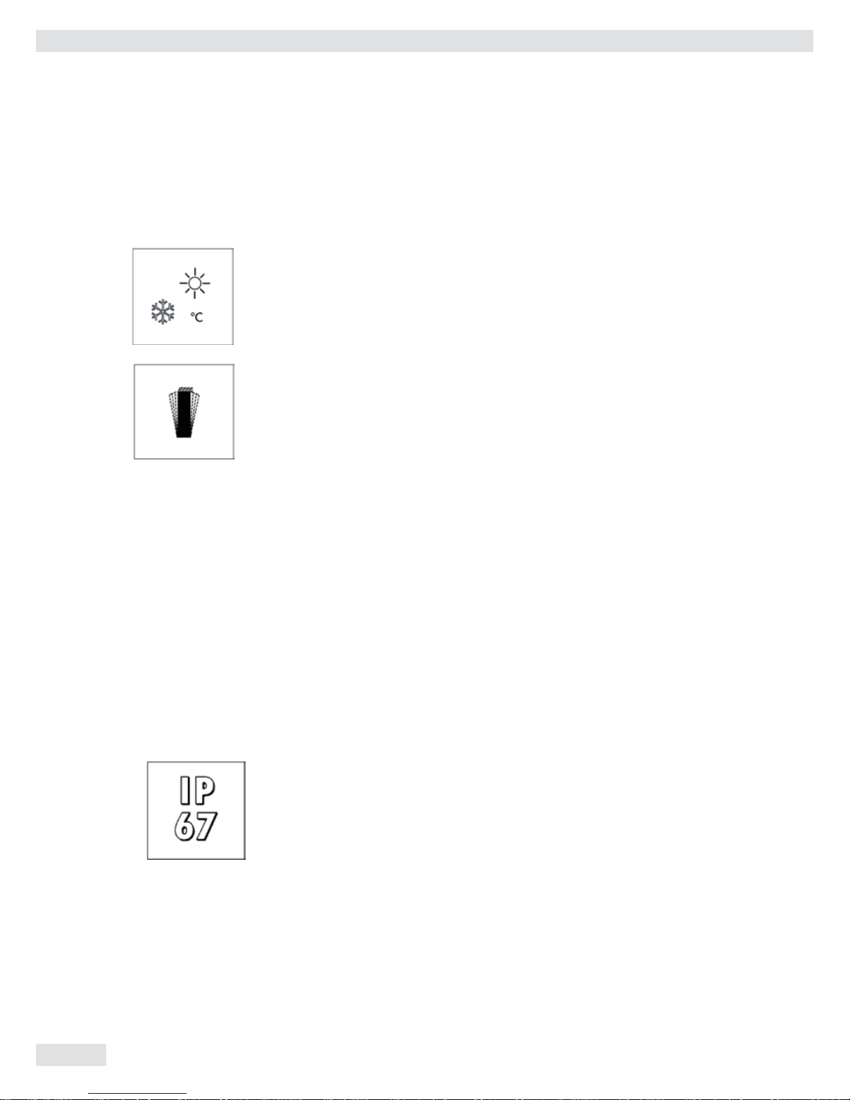
Storage and Shipping Conditions
Allowable storage temperature: – 10°C ... + 40°C
– 14°F ... + 104°F
Allowable storage humidity: 98% relative humidity at 40°C (104°F)
After unpacking the weighing platform, please check it immediately for any
visible damage. If you detect any damage, proceed as directed in the section
entitled „Safety Inspection.“
It is a good idea to save the box and all parts of the packaging until you have
successfully installed the weighing platform. If you need to ship the weighing
platform for any reason, be sure to unplug all connected cables to prevent
damage.
Installation Instructions
5
Safety Instruction
Safety Instructions
The seals affixed to this equipment indicate that only authorized service technicians are
allowed to open the equipment and perform maintenance work so that safe and
trouble-free operation of the equipment is ensured and the warranty remains in
effect.
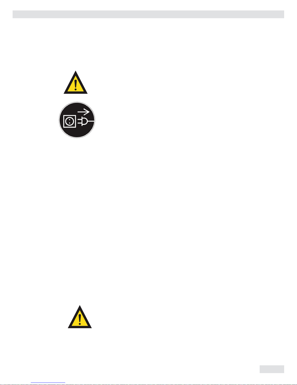
Before opening the weighing cell or A/D converter enclosure, make sure to unplug the
weighing platform from the power supply!
Instructions for Use in Hazardous Areas
Weighing platforms of the series ISI 150IGG-H… and IS300IGG-H comply with the
European Standards EN 50 021: 1999 and EN 5028-1-1-1 according to the
Statement of Conformity, No. TüV 01 ATEX 1739 X, including the 1st and 2nd
Supplements (see “TÜV Certificates”). Therefore, they are suitable for use in
Zones 2 and 22 hazardous areas. Their approval marking is:
h II 3 GD IP67 Eex nR II T6 T80°C
The type of explosion protection used in these weighing platforms involves protection of
the housing against penetration of potentially explosive vapor. For this purpose,
IP67 protection of the platform must be ensured when it is connected to the
power source. Opening the platform or disconnecting cables while the scale is
plugged into the power supply is strictly forbidden. Please read the installation
instructions in the Annex 35751-000-16-A4. To install the power supply, please
follow the installation instructions given in the section entitled “Connecting the
Weighing Platform” in “Getting Started.”
If you will be operating the platform outside the European Community in a Zone
2 hazardous area, you must comply with the national electrical code and
applicable safety regulations of your country. Please ask your local Sartorius
service technician, office or dealer for information on the currently valid
regulations applicable in your country.
The weighing platform may not be operated in Zone 0, 1, 20 or 21 hazardous areas, as it
does not have an EX approval certificate for these areas.
Any tampering with the weighing platform by anyone, other than installation of preload
devices, will result in forfeiture of all claims under the manufacturer‘s warranty.
6
Installation Instructions
Installation Instructions
Installation Instructions
Sartorius dealers or service technicians, who have received special training, will help you
set up the weighing platform and show you how to operate it.
Ambient Conditions
Choose a suitable place to set up the weighing platform. Avoid exposing the weighing
platform to the following ambient conditions:
– Extreme heat radiation
– Extreme vibration
– Places that are difficult to access for cleaning and maintenance
Important Note
If you need to use the weighing platform in areas exposed to heavy traffic (e.g., fork-lift
trucks), you should install a protective frame, consisting of angular braces, around the
weighing platform. To calculate the dimensions for this protective frame, refer to the
section entitled „Dimensions (Scale Drawings).“
Conditioning the Weighing Platform
Do not expose the weighing platform to extreme moisture over long periods. Moisture
in the air can condense on the surfaces of a cold platform whenever it is brought to a
substantially warmer place. If you transfer the weighing platform to a warmer area,
make sure to condition it for about 2 hours at the new ambient temperature, leaving
it unplugged from the power supply. Afterwards, if you keep the weighing platform
connected to the power supply, the continuous positive difference between the
inside of the platform and the outside will practically rule out the effects of moisture
condensation.
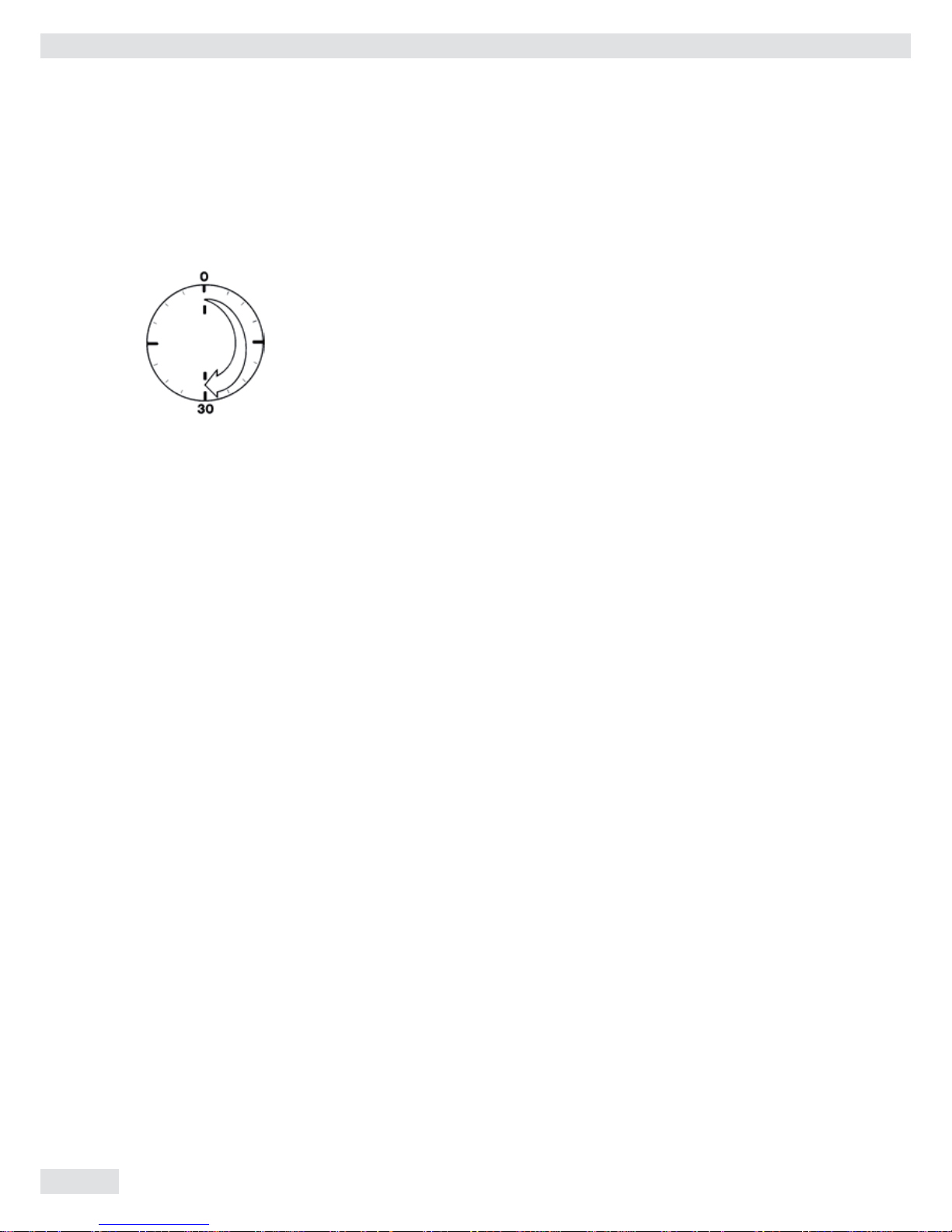
IP67 Protection
In conformance with the IP67 protection rating, the weighing platform will remain
leaktight for 30 minutes if immersed at a depth of 1 meter (approx. 3 ft.).
The IP67 protection of the weighing platform is ensured only under the following
conditions:
– The weighing platform is maintained in the original factory condition
– The rubber seals of the weighing cell and the A/D converter are not perforated
– All cables are securely fastened in place by cable glands
– Both the weighing cell and the A/D converter enclosure are securely closed
Installation Instructions
7
Getting Started
Unpacking the Weighing Platform
Important Note
To install the weighing platform in a pit, please observe the special requirements
given in the section „Pit Installation.“
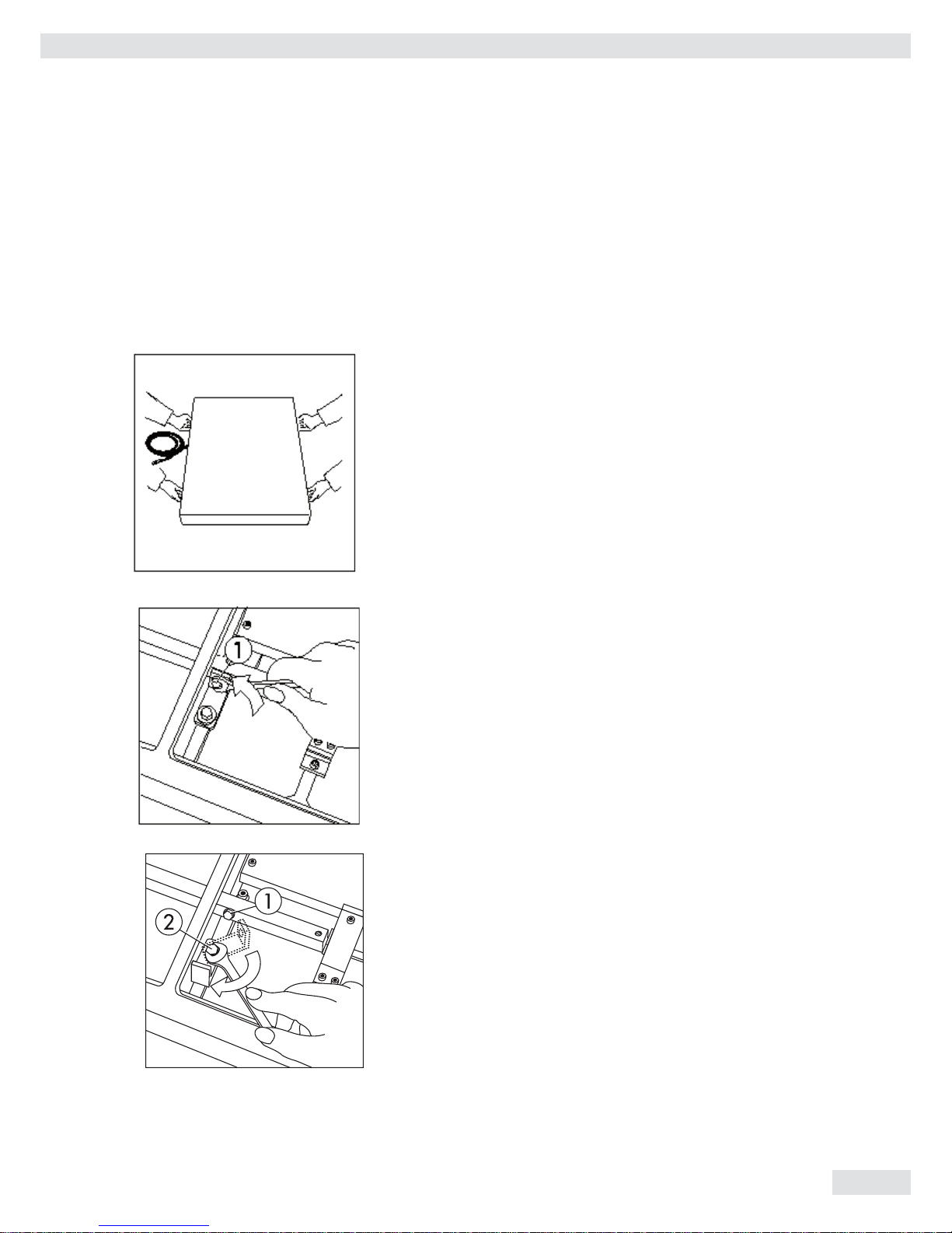
Unpacking the Weighing Platform
- Remove the weighing platform and the load plate from the packaging
- To transport the weighing platform, lift it on both long sides
- Remove the plastic bags, packaging strips and foam material
Removing the Transport Locking Devices
Set up the weighing platform in the vicinity of your work area and remove the
load plate.
Proceed as follows with the red color-coded transport locking device:
- Remove screw 1
- Loosen screw 2 and turn the angular brace by 180°,
refasten screw 2
- Refasten screw 1 to the lever
Important Note on Transporting the Weighing Platform
Follow the above instructions in reverse order to replace the transporting locking
device when transporting the weighing platform.
Getting Started
8
Installation Instructions
Getting Started
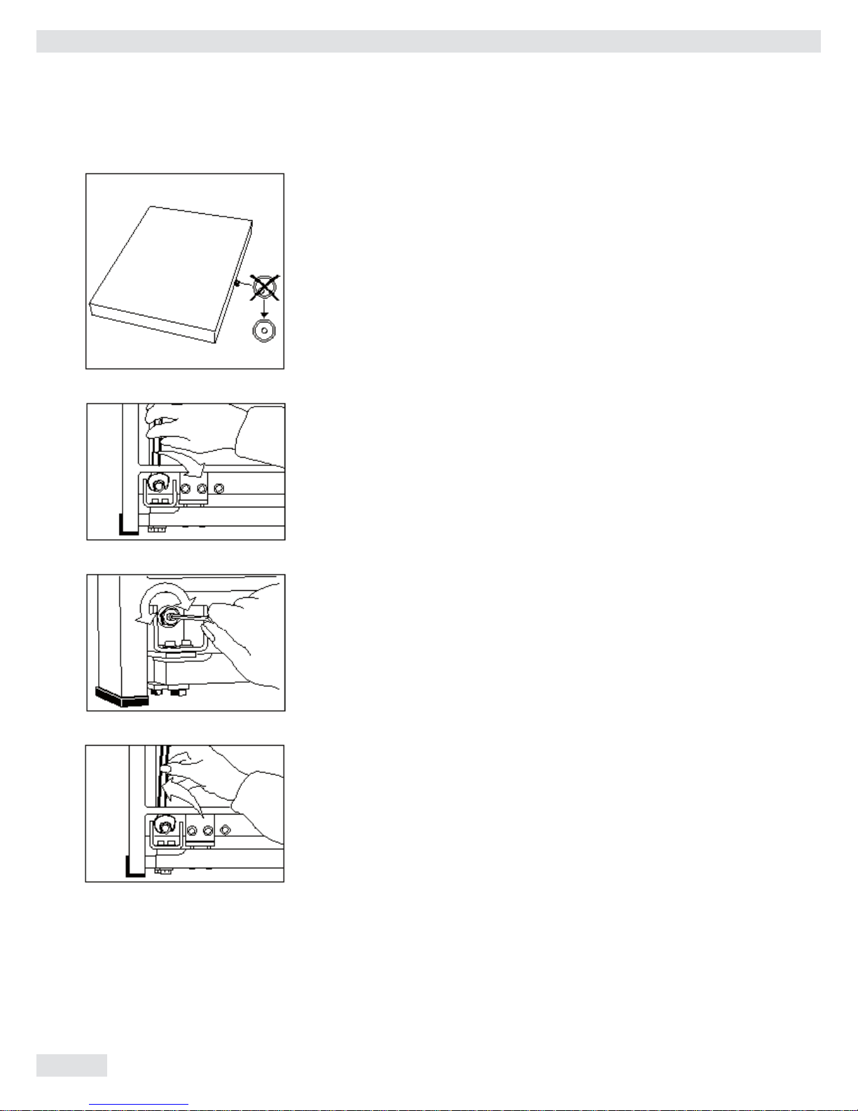
Leveling the Weighing Platform Using the Level Indicator
At the place of installation, level the weighing platform using the leveling feet
so that the air bubble is centered within the circle of the level indicator. Check
to ensure that all 4 leveling feet securely touch the surface and that they equally
support the weight of the platform.
- Remove the load plate
- Loosen the locknuts on the leveling feet using a 17 mm open-end wrench
(spanner)
- Extend or retract the leveling feet using a 5 mm Allen wrench (key)
- After leveling the weighing platform, refasten the locknuts securely against
the platform frame
- Replace the load plate
Installation Instructions
9
Getting Started
Connecting the Weighing Platform
Before initially operating the scale, connect the following cables and completely
assemble the components listed below:
- interface cable to a Sartorius isi industrial terminal or a computer with special
software
- separate power cable for power supply via a Sartorius AC adapter
- components for conveyor systems
Make absolutely sure to unplug the weighing platform from the power supply
before you connect or disconnect any interface cables.
Please note that the person or company who connects any non-Sartoriusapproved indicating and control devices (e.g., a computer) or power supplies to
the weighing platform shall assume all risks and responsibilities associated with
this equipment.
Plug the connecting cable into the connector of a Sartorius isi industrial
terminal. Afterwards, hand-tighten the locking ring. The connecting cable is
6 meters long (approx. 20 feet). To order an extension cable or to customize a
cable to your requirements, refer to the list of accessories or contact Sartorius.
Cable Lengths:
Since you can choose to power the weighing platform via the interface port of
the Sartorius isi industrial terminal or a separate power supply unit, there are a
few restrictions that apply to the cable lengths between these components.
If you use a cable that is longer than 12 meters (∼ 40 feet) between the weighing
platform and the Sartorius isi industrial terminal, each of these components must
be energized by a separate AC adapter.
Note on use in a Zone 11 hazardous area:
The industrial terminal must be mounted securely on a vertical surface so that
the connecting jacks face downwards.
Separate Power Connection for the Weighing Platform
Have your local Sartorius dealer or service technician connect the weighing
platform separately to line current (mains supply). This separate power
connection is required when you use cables that are longer than 12 meters or if
you interface the weighing platform directly with a computer.
10
Installation Instructions
Getting Started
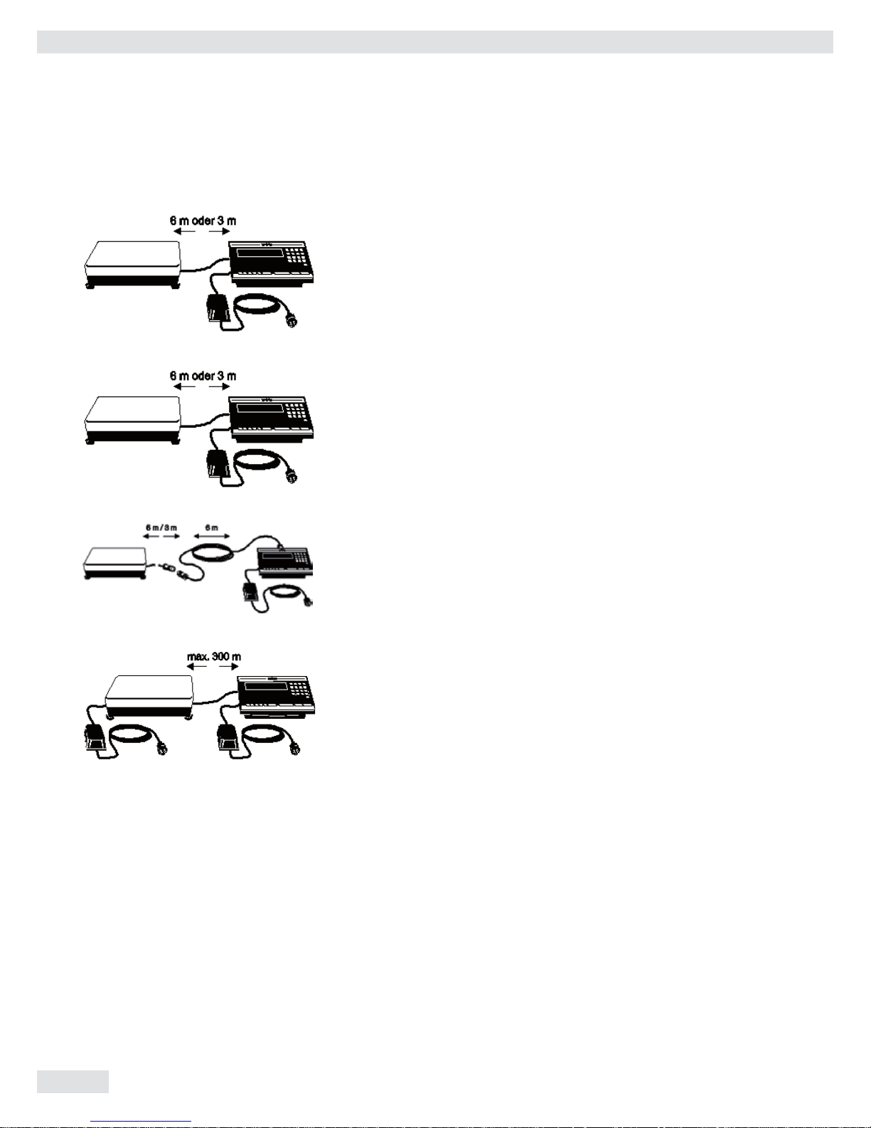
The following diagrams show the options for powering weighing platforms and
industrial terminals.
Cables for connecting the industrial-grade AC adapter, model ING2, to the
„IS“ weighing platform without an extension cord (using the YDO50IS (3m) or
YDO53IS (6m) data output port):
Cables for connecting the industrial-grade AC adapter, model ING2, to the isi
industrial terminal without an extension cord (using the YD050IS (3 m) or the
YD053IS (6 m) data output port):
Cables for connecting the industrial-grade AC adapter, model ING2, only to the
isi industrial terminal with an extension cord:
Connections for cables longer than 12 meters:

Installation Instructions
11
Safety Precautions
Safety Precautions
The weighing platform is energized by an external industrial-grade AC adapter.
Make sure that the voltage rating printed on this unit is identical to your local
line voltage. If the voltage specified on the label or the plug design does not
match the rating or standard you use, please contact your local Sartorius dealer
or office. To use a main feeder cable from the ceiling or to mount a CEE plug,
you will have to make arrangements inside your facilities for installation of such
cable equipment.
Use only original Sartorius AC adapters/power supplies identified by the Sartorius
label. Use of AC adapters/power supplies from other manufacturers, even if these
units have an approval identification marking from a national testing laboratory,
requires the consent of an authorized Sartorius service technician.
For detailed information on further options for powering the weighing platform
(e.g., using local low voltage), contact Sartorius headquarters in Germany or one
of the main offices based in your country.
Hook up the weighing platform to the power supply in conformance with the
installation requirements of your country.
Safety Precautions:
A power supply rated to Industrial Class 2 can be plugged into any electrical
outlet without requiring any additional safety precautions. The ground or
earth terminal is connected to the platform housing, which can be additionally
grounded/earthed, if required.
Install the power cable for connection to an isi industrial terminal or a computer
with adequate protection so that the cable cannot get damaged.
Fixed Power Connection:
If the power cable is permanently installed or secured so that it cannot be
unplugged, the weighing platform must be able to be switched off by a suitable
emergency switch. This emergency switch must be installed near the weighing
platform and be within easy reach. In addition, this switch must be labeled as an
emergency switch. All operators must be shown how to operate this switch.
Operating the Weighing Platform in Zone 2 Hazardous Areas:
If you need to install the platform in Zone 2 hazardous areas, make sure
to comply with the applicable requirements of your country. Installation of
equipment in Zone 2 must be done by a certified technician.The female plug of
the power cable on the industrial-grade power supply must be secured to the
display unit of the weighing platform. The following requirements must be met
for the plug on the other end of the cable:
– either an explosion-protected plug must be installed;
– or the plug must be detached from the power cable and the power cable
permanently secured to a suitable junction box;.
– or the plug must be secured against accidental disconnection
(see Installation Instructions 35751-000-16 AN in this manual).
Connection to the Power Supply in a Zone 2 Hazardous Area:
Brown (live (L)) Blue (neutral (N))
Yellow/green (protective grounding conductor/protective earth)
Whenever possible, avoid wiring your weighing platform into networks that carry
a heavy electrical load (for instance, a compressor or similar equipment).
12
Installation Instructions
Operating Limits
Warm-up Time
The weighing platform will need to warm up for at least 30 minutes after initial
connection to the power supply (or after a relatively long period without power
connection).
Preparing the Weighing Platform for Verification as a Legal Measuring
Instrument in the EU*:
After initially connecting the weighing platform to the power supply, (or after
a relatively long period outage), allow the platform to warm up for at least 24
hours.
*including the Signatories of the Agreement on the European Economic Area
Operating Limits
Maximum Overload Capacity
Sartorius weighing platforms are built so that occasionally loading them
beyond their maximum weighing capacity will not damage them in any way.
The maximum overload capacity of this IS model is 600 kg.
Shock Resistance
Even though Sartorius weighing platforms feature a highly rugged
construction, there are some limits. Avoid dropping objects from considerable
height on the weighing platform and do not expose it to strong side impact.
Sartorius weighing platforms withstand shock according to the shock
response spectrum defined in the IEC68 standard.

Installation Instructions
13
General Instructions
General Instructions for Integration
into Conveyor Systems
The IS weighing platform is suitable for installation in conveyor systems.
Follow the general instructions given below and refer to the „Dimensions (Scale
Drawings)“ to meet the requirements for such installation. Secure the weighing
platform using the appropriate components from the set of fasteners, YAS04 IS.
Any moving or rotating parts intended to be permanently attached to the
load plate must be designed so that they cannot affect the weighing results.
Rotating mechanisms must be properly balanced, for example. In addition,
take care that the fittings do not collide with the parts of the scale platform
mechanism under the load plate. Make sure to remove the load plate from the
platform before drilling.
Any cables or tubing between the weighing platform and other equipment must
not apply any force to the weighing platform. Make sure that cables do not
touch the load plate.
If you install the weighing platform in conveyor systems in Zone 2 or 22
hazardous areas, you must comply with the applicable safety regulations (e.g.,
in Germany with VDE0165). Special precautions must be taken to prevent the
build-up of static electricity caused by moving parts (e.g., roller conveyors).
Preload Range (Zero-Setting Range)
The weight of components that are securely installed on the weighing platform
is called „preload.“ The weighing platform must electrically compensate for this
preload so that the entire weighing range is available and so that it is possible to
zero and adjust (calibrate using external weights) the platform. Higher preloads
may result in a reduction in the maximum weighing capacity.
The following weighing capacities must not be exceeded:
- for the IS 150 IGG--H, at least 30 kg weighing capacity must remain
- for the IS 300 IGG-H, at least 60 kg weighing capacity must remain
Note to Users in the EU *:
Always set the preload prior to verification.
The components for integration into a conveyor must already be installed on the
weighing platform before you connect the platform to the power supply.
*including the Signatories of the Agreement on the European Economic Area
14
Installation Instructions
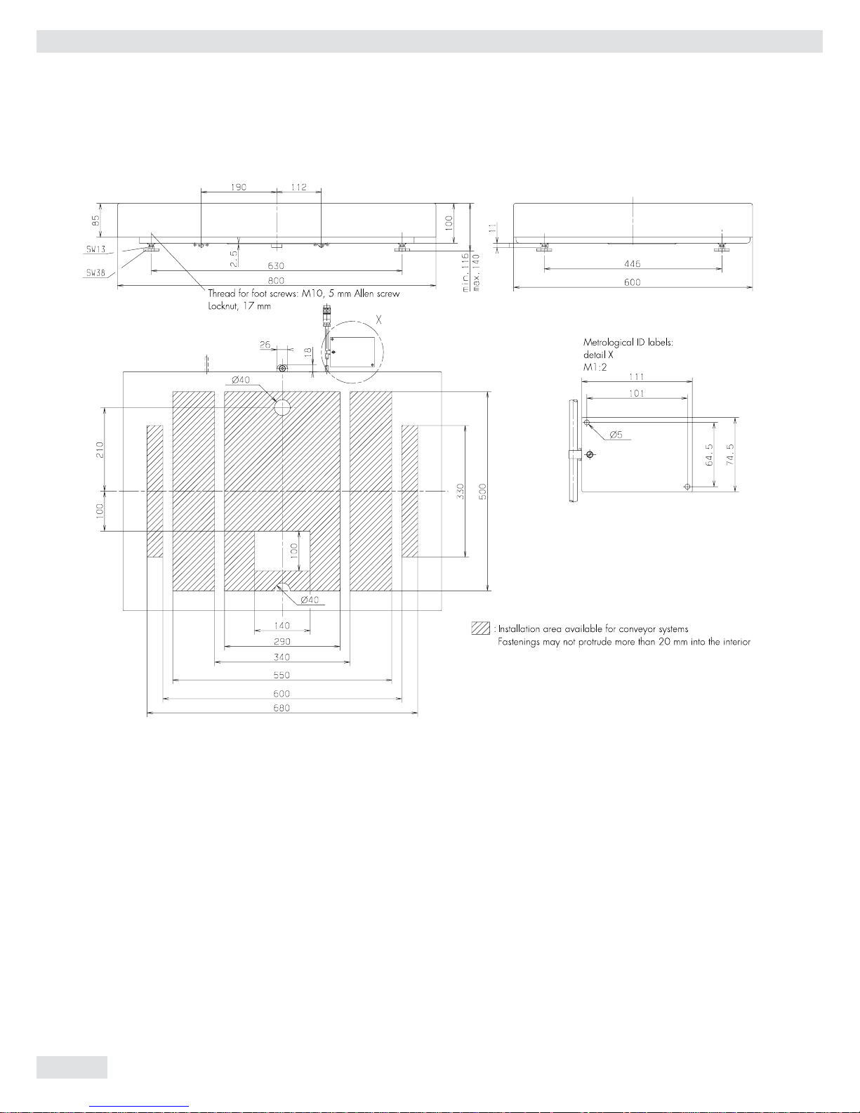
Dimensions
Dimensions (Scale Drawings)
Dimensions in millimeters
Installation Instructions
15
Pit Installation of the Weighing Platform
Pit Installation of the Weighing Platform
Preparation
Choose the appropriate pit frame from the list of accessories.
Note to Users in the EU*
If necessary, the weighing platform can be installed into the pit prior to
initial verification. If a verified weighing platform has been installed, it must
be subsequently verified in compliance with the applicable regulations of your
country.
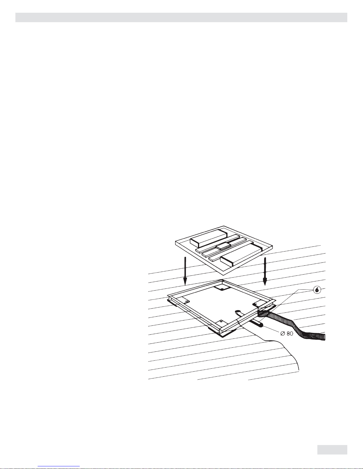
Depending on the size of your weighing platform, excavate the area where
the platform is to be installed according to the diagrams on the following
page. You must connect a drainage system (5) if the weighing platform
will be operated in a wet area. In this case, slope the floor of the pit (8) at
a minimum of 5% toward the drain point. Position a tube (6) with a min.
diameter of 80 mm from a central point of the pit to the location of the
display in order route the signal cable. This will protect the cable, as required.
* including the Signatories of the Agreement on the European Economic Area
16
Installation Instructions
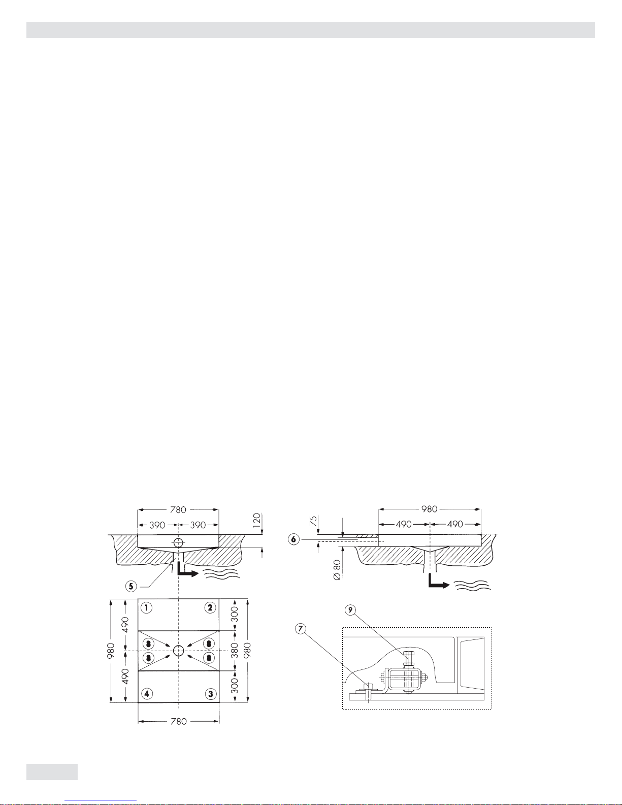
Installation of a Pit Frame
Installation of a Pit Frame
- Remove the screws (7), washers and the metal plates of the pit frame
- Place tape over the threads of the pit frame
- Lower the frame into the pit
- Ensure that the contact areas of the pit frame (1), (2), (3) and (4) are completely level
- The pit frame must carry at least half the maximum weighing capacity of the platform
on each side
- Adjust the height by placing thin metal plates (7) underneath the pit frame. Back fill
with concrete and allow area to dry.
Positioning and Connecting the Weighing Platforms (Your Sartorius Service Technician
Will Help You )
- Remove the load plate, the level indicator and leveling feet
- Take the 4 hexagon bolts, M 10x70, from the set of fasteners, YAS 04 IS, attach the
locknuts to them and screw them into the threads for the leveling feet (foot screws).
Tighten the bolts.
- Remove the transport locking devices as described on page 7.
- Loosely attach the 4 angular braces to the frame of the weighing platform using the
screws (7) and washers from the set of fasteners.
- Push the connecting cable through the tube (6) and lower the weighing platform into
the pit frame.
- Loosely attach the angular braces to the pit frame using the screws of the pit frame.
- Center the weighing platform with respect to the pit frame.
- Adjust the height of the weighing platform with the 4 hexagon bolts (9), M 10x70. Fix
the screws with the locknuts and tighten the screws of the angular braces.
- Refit the load plate.
- Use the handles provided in the set of fasteners to remove the load plate.
Pit Construction Diagrams:
 Loading...