


Sartorius IS06BBE-SX,IS16EDE-HX,IS12CCE-SX,IS34EDE-HX,IS64EDE-SX,IS2CCE-SX,IS300IGG-HX,IS150IGG-HX,IS6CCE-SX Installation And Safety Instructions

98648-009-44
Installation and Safety Instructions | Installation und Sicherheitshinweise |
Conseils d’installation et de sécurité | Advertencias de instalación y medidas de seguridad |
Istruzioni di installazione e di sicurezza | Installatie- en veiligheidsinstructies |
Notas de instalação e de segurança | Installations- och säkerhetsanvisningar | Asennus- ja turvaohjeet |
Installations- og sikkerhedsanvisninger |
Υποδεξεις εγκατστασης και ασφαλεας
Sartorius
IS...-.X-Models
Digital Weighing Platforms
for Use in Hazardous Areas/Locations
IS...-.X-Modelle
Digitale Wägeplattformen
für explosionsgefährdete Bereiche
Modèles IS...-.X
Plates-formes de pesée numériques
pour les domaines à risques d’explosions
Modelos IS...-.X
Plataformas de pesaje digitales
en atmósferas potencialmente explosivas
Modelli IS...-.X
Piattaforme di pesata digitali
per aree a pericolo di esplosione
Modellen IS...-.X
Digitale weegplatformen
voor explosiegevaarlijke ruimten
Modelos IS...-.X
Plataforma digital de pesagem
para aplicação em áreas de perigo de explosão
IS...-.X-modeller
Digitala vågplattformar
för explosionsfarliga miljöer
IS...-.X-mallit
Räjähdysvaarallisiin tiloihin
sopivat digitaaliset punnitusalustat
IS...-.X-modeller
Digitale vejeplatforme
til eksplosionsfarlige områder
Μοντλο IS...-.X
Ψηφιακο δσκοι ζγισης για
περιοχς µε κνδυνο κρηξης
Γλσσες

2
English – page 3
In cases involving questions of interpretation,
the German-language version shall prevail.
Deutsch – Seite 13
Im Auslegungsfall ist die
deutsche Sprache maßgeblich.
Français – page 23
En cas de questions concernant l’interprétation,
la version en langue allemande fera autorité.
Español – página 33
En caso de interpretación, la versión
en lengua alemana será determinante.
Italiano – pagina 43
In caso di interpretazione, fa testo
la versione in lingua tedesca.
Nederlands – pagina 53
Português – página 63
Svenska – sidan 73
Suomi – sivu 83
Dansk – side 93
Ελληνικ – Σελδα 103

3
4 Warning and Safety Information
6 Installation Instructions
11 Installation
12 Care and Maintenance
The following symbols are used in
these instructions:
§ indicates required steps
$ indicates steps required only under
certain conditions
> describes what happens after you
have performed a certain step
– indicates an item in a list
!indicates a hazard
Make sure you observe the following
warning and safety information in
its entirety during installation and
operation, as well as while performing
maintenance and repair work on
the equipment. It is important that
all personnel using the equipment
understand this information, and have
access to it at all times. Furthermore,
the warning and safety information
supplied with any electrical equipment
connected, such as peripheral devices,
must be observed as well. The warning
and safety information can be supplemented by the equipment operator.
Make sure all operating personnel are
informed of any additions to these
instructions.
Contents

4
Warning and Safety Information
General Provisions
The IS...-.X weighing platforms meet
the requirements for Group II, Category
2 equipment (and Category 1 in some
cases; see table below) in accordance
with EC Directive 94/9/EEC and
bear markings in accordance with
KEMA EC type-examination certificate
ATEX1099X.
Furthermore, these platforms meet
the EC Directives for electromagnetic
compatibility (see the Declaration of
Conformity in the enclosed installation
instructions). Improper use or handling,
however, can result in damage and/or
injury.
- The permitted uses of the weighing
platforms are specified in the typeexamination certificate. Be sure to
observe all restrictions listed in the
type-approval certificate. Operating
the weighing platform outside of these
restrictions is not permitted, and is
considered use of the equipment for
other than its intended purpose.
Ask your local Sartorius office or dealer
for information on the legal regulations
applicable in your country.
- Installation in a Zone 1 or 2 hazardous
area or Class I, Division 1 or 2 hazardous location must be performed by a
trained technician who is familiar with
the assembly, start-up and operation
of the system. The trained technician
must also have the required qualifications and be familiar with the relevant
guidelines and regulations. If you need
assistance, contact your Sartorius dealer
or the Sartorius Service Center. Any
installation work that does not conform
to the instructions in this manual will
result in forfeiture of all claims under
the manufacturer’s warranty.
- The IS...-.X weighing platforms may
be used and operated by qualified
personnel only. If the equipment
housing is opened by anyone other
than persons authorized by Sartorius,
this will negate its conformity with
regulations governing use in the stated
hazardous areas/locations and result
in forfeiture of all claims under the
manufacturer’s warranty.
- Chemicals (e.g., gases or dusts) that
can corrode and damage the inside
or outside of the device must be
kept away from the equipment.
The relevant specifications are listed
in the type-examination certificate
included with this equipment.
- The casing on all connecting cables,
as well as the casing on wires inside the
equipment housing, is made of PVC.
Chemicals that corrode these materials
must be kept away from these cables.
Cabling: The casing of the power cable
on AC adapter/power supply models
YPS02-Z.., -XDR, -XKR and -XAS is
made of rubber.
- Do not expose the IS...-.X to aggressive
chemical vapors or to extreme temperatures, moisture, shocks, or vibration.
The allowable operating temperature
range during operation is 0°C to 40°C
(32°F to 104°F).
Please observe the following when
installing the weighing system
- Always comply with the applicable
accident prevention regulations.
- If you use cables purchased from
another manufacturer, check the pin
assignments. Before connecting the
cable to Sartorius equipment, check
the pin assignments in the cable
against those specified by Sartorius and
disconnect any wires that are assigned
differently. The operator shall be solely
responsible for any damage or injuries
that occur when using cables not
supplied by Sartorius. Use only original
Sartorius spare parts.
- In the hazardous area/location, place a
protective cap over the female interface
connector if no interface is connected.
Make sure the IP protection is not
damaged during installation.
- Handle the equipment as specified
in EN 60529 (in Germany: VDE 0470
Part 1) in accordance with its protection
(IP) rating. Refer to the table above for
the IP protection ratings of the IS...-.X
models. The protection rating of
the accessories designed for use in
hazardous areas/locations is IP65.
- Avoid exposing the equipment to
static electricity; be sure to connect
the equipotential bonding conductor.
Disconnecting equipotential bonding
conductors is not permitted.
- You can connect a maximum of
8 weighing platforms with bus-capable
RS-485 data output ports over a Zener
barrier (for example, YDI01-Z).
For the User
- Have the equipment inspected at
appropriate intervals for correct
functioning and safety by a trained
technician.
- Always make sure the IS...-.X weighing
platform is disconnected from AC
power before performing any installation, cleaning, maintenance or repair
work.
- When using the weighing equipment
in hazardous areas/locations, make
sure there is no current or voltage in
the equipment before connecting or
disconnecting current-carrying cables
to or from the equipment. Disconnect
the weighing equipment from AC power
before connecting or disconnecting
cables.
- If you see any indication that the
IS...-.X weighing platform cannot be
operated safely (for example, due to
damage), turn off the platform and lock
it in a secure place so that it cannot
be used for the time being. Make sure
the applicable accident prevention regulations are observed by all operating
personnel.
- The IP protection rating is ensured only
if the rubber gasket is installed correctly
and all cable gland screw fasteners are
connected securely. Any installation
work that does not conform to the
instructions in this manual will result
in forfeiture of all claims under the
manufacturer’s warranty.
- Make sure that at least one person
among the operating personnel knows
the importance and function of the
emergency shutoff system and portable
safety equipment. The same person
must also be familiar with the location
and operation of the fire extinguisher.
Make sure the emergency shutoff
system is accessible at all times.

5
Model series Marking (ATEX) Use in IP rating Markings in acc. with FMRC Use in
Zone approval for USA and CSA
approval for Canada
IS..BBE-.X 1, 2 (gas) IP 54 IS CL I, DIV 1, GR A,B,C,D, T4 Class I, Division 1 (gas)
II 2 G EEx ib IIC T4 CL l, ZONE 1 AEx ib IIC T4 Class I, Zone 1 (gas)
IS..CCE-.X 1, 2 (gas) IP 54 IS CL I, DIV 1, GR A,B,C,D, T4 Class I, Division 1 (gas)
II 2 G EEx ib IIC T4 CL l, ZONE 1 AEx ib IIC T4 Class I, Zone 1 (gas)
IS…EDE-.X 1, 2 (gas) IP 65 IS CL I, DIV 1, GR A,B,C,D, T4 Class I, Division 1 (gas)
II 2 G EEx ib IIC T4 CL l, ZONE 1 AEx ib IIC T4 Class I, Zone 1 (gas)
20, 21, 22 IP 65 IS CL II,III, DIV 1, GR E,F,G, T4 Class II,III Division 1
II 1 D T135°C (dust) (dust + fibers)
IS… IGG-HX 1, 2 (gas) IP 65 and IP 67 IS CL I, DIV 1, GR A,B,C,D, T4 Class I, Division 1 (gas)
II 2 G EEx ib IIC T4 CL l, ZONE 1 AEx ib IIC T4 Class I, Zone 1 (gas)
20, 21, 22 Class II,III Division 1
II 1 D T135°C (dust) IP 65 and IP 67 IS CL II,III, DIV 1, GR E,F,G, T4 (dust + fibers)

6
Installation Instructions
Unpacking the Equipment
§ After unpacking the equipment,
please check it immediately for any
visible damage.
$ If you detect any damage, proceed
as directed in the chapter entitled
“Care and Maintenance,” under
“Safety Inspection.”
$ It is a good idea to save the box and all
parts of the packaging until you have
successfully installed your equipment.
Only the original packaging provides
the best protection for shipment.
$ Before packing your equipment, unplug
all connected cables to prevent damage.
Equipment Supplied
The equipment supplied includes
the components listed below:
IS06BBE-SX
– Weighing platform with data interface
– Dust cover
– Shield ring
– Pan support
– Load plate
– Glass draft shield/Draft shield
– Draft shield cover
IS2CCE-SX , IS6CCE-HX
– Weighing platform with data interface
– Dust cover
– Pan draft shield
– Load plate
IS6CCE-SX, IS12CCE-SX
– Weighing platform with data interface
– Dust cover
– Load plate
IS16EDE-HX, IS34EDE-HX, IS64EDE-SX
– Weighing platform with data interface
– Load plate
IS150IGG-HX, IS300IGG-HX
– Weighing platform with data interface
(junction box)
– Load plate
Requirements for the Place of
Installation
The weighing platform is designed to
provide reliable results under normal
ambient conditions. When choosing
a location to set up your weighing
platform, observe the following so that
you will be able to work with added
speed and accuracy:
– Set up the weighing platform on
a stable, even surface
– Avoid placing the weighing platform in
close proximity to a heater or otherwise
exposing it to heat or direct sunlight.
– Protect the weighing platform from
drafts that come from open windows
or doors.
– Avoid exposing the weighing platform
to extreme vibrations during weighing.
– Protect the weighing platform from
aggressive chemical vapors.
– Do not expose the weighing platform
to extreme moisture over long periods.
Turn off the power when the weighing
system is not in use.
Conditioning the Weighing Platform
Moisture in the air can condense on
the surface of a cold weighing platform
whenever it is brought to a substantially
warmer place. If you transfer the weighing platform to a warmer area, make
sure to condition it for about 2 hours at
room temperature, leaving it unplugged
from AC power. Afterwards, if you keep
the weighing platform connected to AC
power, the constant positive difference
in temperature between the inside of
the weighing platform and the outside
will practically rule out the effects of
moisture condensation.
§ Prepare a suitable place of installation
for the weighing platform. The place
of installation should be dry, level
and even. The allowable operating
temperature range is 0°C to +40°C
(32°F to 104°F).
§ If the weighing platform is in a
hazardous area/location, it must
be grounded (i.e., an equipotential
bonding conductor must be connected).
This connection must be made by a
trained technician. All IS...-.X weighing
platforms are equipped with a terminal
for connecting the grounding conductor. The grounding conductor is
connected to a threaded bolt or terminal
screw, or a bore hole is provided. If a
bore hole is provided, use a stainless
steel screw and nut to connect the
grounding conductor. Use of a tooth
lock washer is recommended to prevent
the screw from coming loose. The wire
used for the grounding conductor
should have a cross-sectional diameter
of at least 4 mm
2
, with a suitable ring
lug attached. Connect all equipment,
including peripheral devices, to the
equipotential bonding conductor.
When connecting the platform to
the indicator (for models IS16EDE-HX,
IS34EDE-HX, IS64-EDE-SX,
IS150IGG-HX, IS300IGG-HX), use only
cabling and extensions approved by
Sartorius, as these are made in accordance with the restrictions on permissible cable lengths imposed by both the
capacitance and inductivity values (see
the “Schedule to EC Type-Examination
Certificate” in the operating instructions)
and the requirements for electromagnetic compatibility.
Before putting the weighing system
into operation for the first time, make
sure there is no hazard of explosion
present at the place of installation.
If there is any indication that the equipment does not function properly (e.g.,
display remains blank, or no display
backlighting) due to damage during
transport, disconnect the equipment
from power and notify your nearest
Sartorius Service Center. The specifications for Ui, Li, Pi, Ta, temperature
class, Ci, and Li for IS...-.X weighing
platforms are listed in the EC typeexamination certificate. The EC typeexamination certificate also specifies
which accessories are permitted for
connection. These specifications must
be taken into account when connecting
accessory equipment to the platform.
The explosion-protected weighing platform must be set up in accordance with
acknowledged technological standards.
These include the national laws and
regulations applicable at the place
of use. In particular, the conditions
described under Item 17 of the KEMA
EC type-examination certificate,
“Special Conditions for Safe Use,” must
be observed. Furthermore, national
regulations for accident prevention
and environmental protection must
be observed at all times.
Before the weighing system is operated
in a hazardous area/location, it must be
inspected either by a certified electrician
or under the guidance and supervision
of a certified electrician to make sure
that the weighing system complies with
the applicable regulations (in Germany,
Section 12 of the ElexV). Determine
whether the installation must be
registered with technical inspection
authorities (such as the trade board)
in your country. Observe all safety
instructions. Regular inspections
must also be performed on the system
during operation. The system should
be inspected at intervals scheduled to
allow for the prevention or early detection of defects that arise as a result of
normal wear and tear. The longest
permissible interval period is 3 years.
Make sure all relevant conditions are
met when installing the equipment and
during operation (for example, conditions imposed by an employers’ liability
insurance association). When performing inspections, generally acknowledged
rules of engineering relevant to these
conditions must also be applied.
If the equipment housing is opened by
anyone other than persons authorized
by Sartorius, or if the equipment is
installed or operated incorrectly, this
will result in forfeiture of the approval
for use in the stated hazardous
area(s)/location(s) and of all claims
under the manufacturer’s warranty.

7
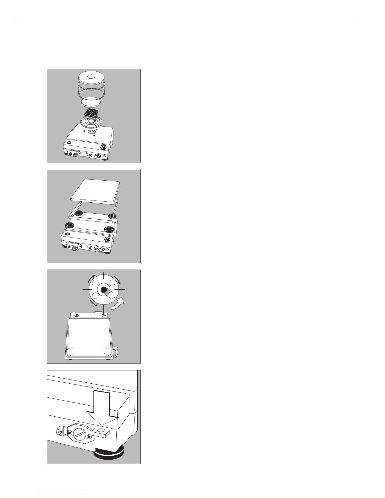
Setting Up the Weighing Platform
Model IS06BBE-SX
§ Position the components listed below in the order given:
– Dust cover
!When using the dust cover in a hazardous area/location, make sure the weighing
platform is set up and operated in such a manner that the risk of ignition due to static
electricity is avoided. See also the instructions on the dust cover.
– Place the shield ring on the weighing platform and turn it counterclockwise until it
is seated firmly.
– Pan support
– Load plate
– Glass draft shield
– Draft shield cover
Models IS2CCE-SX, IS6CCE-SX
§ Position the components listed below in the order given:
– Dust cover (remove plastic from adhesive surface)
!When using the dust cover in a hazardous area/location, make sure the weighing
platform is set up and operated in such a manner that the risk of ignition due to static
electricity is avoided. See also the instructions on the dust cover.
– Pan draft shield (depending on platform model)
– Load plate
Models IS6CCE-SX, IS12CCE-SX
– Dust cover
– Load plate
Leveling the weighing platform using the level indicator:
Models IS06BBE-SX, IS2CCE-SX, IS6CCE-HX, IS6CCE-SX, IS12CCE-SX
At the place of installation, level the weighing platform using the leveling feet so that
the air bubble is centered within the circle on the level indicator. Check to ensure that
all four feet rest securely on the work surface. Adjust only the 2 front feet to level the
weighing platform.
– Retract the 2 rear feet
– Turn the 2 front feet until the air bubble is centered in the level indicator.
– Extend the 2 rear feet until they rest on the work surface.
Anti-theft Locking Device
– Use the lug located on the back of the weighing platform to attach an anti-theft locking
device (models IS06BBE-SX, IS2CCE-SX, IS6CCE-HX, IS6CCE-SX, IS12CCE-SX only).
For example, attach a lock, chain or steel cable to secure the weighing platform.
R
L
L
R
L
R

8
Below-Platform Weighing
– A port for a below-platform weighing hanger is located on the bottom of the platform
(models IS06BBE-SX, IS2CCE-SX, IS6CCE-HX, IS6CCE-SX and IS12CCE-SX only).
– Remove the cover plate from the bottom of the platform
– Attach the sample to a hook (e.g., a bent wire) suspended from the below-platform
weighing port. (If necessary, install a shield for protection against drafts.)
Setting up the weighing platform:
IS16EDE-HX, IS34EDE-HX, IS64EDE-SX
– Place the load plate on the weighing platform
Leveling the weighing platform using the level indicator:
Models IS16EDE-HX, IS34EDE-HX, IS64EDE-SX
At the place of installation, level the weighing platform using the leveling feet so that
the air bubble is centered within the circle on the level indicator. Check to ensure that
all four feet rest securely on the work surface.
– To raise the weighing platform, extend the leveling feet (turn clockwise).
– To lower the weighing platform, retract the leveling feet (turn counterclockwise).
Below-Platform Weighing
Models IS16EDE-HX, IS34EDE-HX, IS64EDE-SX
– A port for a below-platform weighing hanger is located on the bottom of the
weighing platform.
– Remove the cover plate from the bottom of the platform
– Attach the sample to a hook (e.g., a bent wire). Install the hook in the below-platform
weighing port. You can order the hook directly from Sartorius AG. (If necessary, install
a shield for protection against drafts.)

9
Leveling the weighing platforms using the level indicator:
Models IS150IGG-HX, IS300IGG-HX
– Weighing platform with load plate
– Position the weighing platform at the place of installation and remove the load plate.
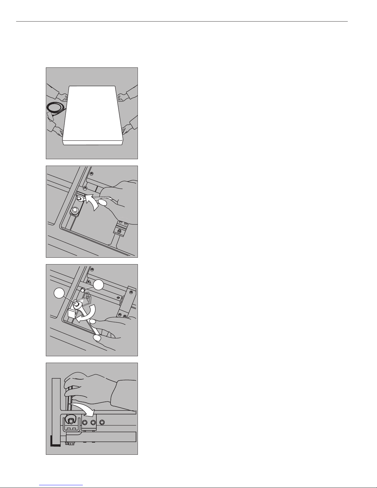
Removing transport locking devices:
Models IS150IGG-HX, IS300IGG-HX
Proceed as follows, working on the locking device marked in red:
– Remove screw 1 (see below).
– Loosen screw 2, turn the locking device 180°, and tighten screw 2 again.
– Tighten screw 1 on the lever.
Notes on transporting the weighing platform:
Replace the transport locking device before moving or shipping the weighing platform.
1
2

10
Leveling the weighing platforms using the level indicator:
Models IS150IGG-HX, IS300IGG-HX
– Remove the load plate
– Loosen the locknuts on the leveling feet using an SW 17 open-end wrench (spanner).
– Use an Allen wrench (Allen key) to retract or extend the leveling feet.
§ At the place of installation, level the weighing platform using the leveling feet so
that the air bubble is centered within the circle of the level indicator.
Make sure all 4 feet rest on the work surface so that during operation, the load will
distributed evenly over the weighing platform.
– To raise the weighing platform, extend the leveling feet (turn clockwise).
– To lower the weighing platform, retract the leveling feet (turn counterclockwise).
– After leveling the weighing platform, tighten the lock nuts against the platform frame.
– Place the load plate on the platform

11
Connecting the Weighing Platform to AC Power
!Please follow the safety instructions.
§ If the local line voltage/frequency or plug design does not match equipment
requirements, please contact the supplier.
!Use only original Sartorius power supplies.
Power supply for installation in hazardous areas/locations:
– Power supply: YPS02-X.. (for use with all IS...-.X models)
Installation in a Zone 1 hazardous area or Class I, Division 1 hazardous location must
be performed by a trained technician.
– Please make sure the currently valid regulations and guidelines for installing equipment
in the areas listed above (e.g., EN60079-14 or, in Germany, ElexV) are strictly observed.
The power cord must be connected to a suitable terminal box (open cable ends).
Brown (Live – L –)
Blue (Neutral – N –)
Yellow/green (protective conductor – PE –)
!Within the hazardous area/location, connect the following devices to a central
equipotential grounding busbar:
– Weighing platform
– Power supply
– Zener barrier
AC adapter for installation outside the hazardous area/location:
– AC adapter: YPS02-Z.., (for use with all IS...-.X models)
Please observe the following when operating the weighing platform in a Zone 1
hazardous area/Class I, Division 1 hazardous location:
§ Attach the female connector of the Ex-power supply cable to the weighing platform
and secure the connection with the threaded ring
!Make sure when installing the power cable that it is protected from damage
Note on connecting weighing platform models IS150IGG-HX and IS300IGG-HX:
The weighing platform is powered through round plug-in connector no. 1
(see illustration on the left).
Plug-in connector no. 2 is used for data transfer.
Connecting Electronic Peripheral Devices
§ Make absolutely sure to unplug the weighing platform from AC power before you
connect or disconnect a peripheral device (printer or PC) to or from the interface port.
Warmup Time
Allow the weighing instrument to warm up for at least 30 minutes after connection
to power or following a long power outage. Only after this time will the device have
reached the required operating temperature.
Installation
1
2

12
Care and Maintenance
Service
Regular servicing by a Sartorius technician will extend the service life of your
weighing platform and ensure its continued weighing accuracy. Sartorius can
offer you service contracts, with your
choice of regular maintenance intervals
ranging from 1 month to 2 years.
Repairs
!Do not open the power supply (for
example, the YPS02-X..) while it is
under current. Allow approximately
10 seconds to elapse after disconnecting the equipment from power before
opening the equipment housing.
Because the fitting of adjoining
surfaces is critical for the safety rating
of the equipment housing, the housing
must be opened and closed by a trained
technician. Make sure the required
torque is applied when closing the
housing. Scratches on the adjoining
surfaces that are decisive for the safety
rating of the equipment will terminate
the approval of the equipment for use
in hazardous areas/locations.
!Disconnect defective equipment from
power immediately. Repairs may be
performed only by authorized Sartorius
service technicians using original
Sartorius parts. Any attempt by
untrained persons to perform repairs
may lead to hazards for the user.
!If a cable or cable gland is damaged
or defective, replace the cable as a
complete unit with all its connectors.
Cleaning
!Make sure that no liquid penetrates
the weighing platform housing.
$ Unplug the weighing instrument from
power before cleaning. Clean the
weighing instrument regularly to
remove all impurities.
$ Use a damp cloth to wipe down the
equipment. The leveling feet are
covered with rubber buffers. In hazardous areas/locations, use only a damp
cloth to clean the rubber buffers; this
prevents build-up of static electricity.
Devices with protection rating IP65 can
be rinsed down with a jet of water that
strikes the load plate from above.
!Do not use high-pressure cleaning
equipment to clean the weighing
platform.
> If the water that you use to clean the
weighing platform is too hot or too
cold, the difference in temperature
between the water and the weighing
platform can cause condensation inside
the weighing platform housing. This
condensation may cause the weighing
platform to malfunction.
Cleaning Stainless Steel Surfaces
Clean all stainless steel parts regularly.
Remove the stainless steel load plate
and thoroughly clean it separately,
outside the hazardous area/location.
Use a damp cloth or sponge to
clean any stainless steel parts on the
weighing platform. You can use any
commercially available household
cleaning agent that is suitable for
use on stainless steel. Clean stainless
steel surfaces by wiping them down.
Then clean the load plate thoroughly,
making sure to remove all residues.
Use a damp cloth or sponge to wipe
down any stainless steel parts on the
weighing platform again. Afterwards,
allow the weighing platform to dry.
If desired, you can apply oil to
the cleaned surfaces as additional
protection.
!Do not use stainless steel cleaning
agents that contain soda lye (caustic),
acetic acid, hydrochloric acid, sulphuric
acid or citric acid. The use of scrubbing
sponges made with steel wool is not
permitted.
Solvents are permitted only for cleaning
stainless steel parts.
Corrosive Environment
$ Remove all traces of corrosive
substances from the weighing platform
on a regular basis.
Cleaning the Dust Cover
(Only for Models IS06BBE-SX,
IS2CCE-SX, IS6CCE-HX, IS6CCE-SX,
IS12CCE-SX)
!Clean the dust cover only outside the
hazardous area/location.
!Wiping or rubbing the dust cover with
a dry cloth is not permitted.
$ After the cleaning the dust cover,
discharge any static electricity; for
example, by wiping down all surfaces
with a damp, grounded cloth.
Replacing the Dust Cover
> Replace damaged dust covers.
§ Place the new dust cover on the IS...-.X
and press down on the front and back
along the edges until the cover is firmly
seated.
Safety Inspection
If there is any indication that safe
operation of the IS...-.X is no longer
warranted:
§ Disconnect the equipment from power
> Lock the IS...-.X in a secure place to
ensure that it cannot be used for the
time being. Safe operation of the
power supply is no longer ensured
when:
– there is visible damage to the power
supply
– the power supply no longer functions
properly
– the equipment has been stored for a
relatively long period under unfavorable
conditions
– the equipment has been subjected to
rough handling during shipment.
In this case, notify your nearest
Sartorius Service Center. Maintenance
and repair work may be performed only
by service technicians who are authorized by Sartorius and who:
– have access to the required main-
tenance and repair manuals, and
– have attended the relevant service
training courses.
!The seals affixed to this equipment
indicate that only authorized service
technicians are allowed to open the
equipment and perform maintenance
work so that safe and trouble-free
operation of the equipment is ensured
and the warranty remains in effect.
Storage and Shipping Conditions
$ The packaging used for shipping your
Sartorius equipment is optimally
designed to prevent damage during
transport. It is a good idea to save
the box and all parts of the packaging
for future storage or shipment of
the equipment. Only the original
packaging provides the best protection
for shipment.
$ Allowable storage temperature:
– 20°C to + 75°C (– 4°F to + 167°F)
$ Allowable humidity during storage:
max. 90%
$ Please refer to the information under
“Warning and Safety Information.”
Instructions for Recycling the
Packaging
If you no longer need the packaging
after successful installation of the
equipment, you should return it for
recycling. The packaging is made from
environmentally friendly materials and
is a valuable source of secondary raw
material. For information on recycling
options, including recycling of old
weighing equipment, contact your
municipal waste disposal center or
local recycling depot.

13
14 Sicherheits- und Warnhinweise
16 Aufstellhinweise
21 Installation
22 Pflege und Wartung
Folgende Symbole werden in dieser
Anleitung verwendet:
§ steht vor Handlungsanweisungen
$ steht vor Handlungsanweisungen, die
nur unter bestimmten Voraussetzungen
ausgeführt werden sollen
> beschreibt das, was nach einer ausge-
führten Handlung geschieht
– steht vor einem Aufzählungspunkt
!weist auf eine Gefahr hin
Die Sicherheits- und Warnhinweise
sind in ihrer Gesamtheit bei der
Installation, beim Betrieb, bei der
Wartung und Reparatur des Gerätes
zu beachten. Diese Hinweise sollten
von allen Beteiligten verstanden und
stets griffbereit sein. Die Sicherheits-
und Warnhinweise in den Unterlagen
der angeschlossenen elektrischen
Betriebsmittel wie z.B.: Zubehör, sind
ebenso zu beachten. Diese Sicherheits-
und Warnhinweise sind ggf. durch den
Betreiber zu ergänzen. Das Bedien-
personal ist entsprechend einzuweisen.
Inhalt

14
Sicherheits- und Warnhinweise
Allgemeine Bestimmungen
Die IS...-.X Modelle erfüllen die Anforderungen der EG-Richtlinie 94/9/EG für
Geräte der Gerätegruppe II, Kategorie 2
oder auch Kategorie 1 (siehe Tabelle)
und sind gemäß EG-Baumusterprüfbescheinigung KEMA 01ATEX1099X
gekennzeichnet.
Ferner erfüllen die IS...-.X Modelle
die Anforderungen der EG-Richtlinien
für elektromagnetische Verträglichkeit
und elektrische Sicherheit (siehe
Konformitätserklärungen in der
beiliegenden Betriebsanleitung).
Ein unsachgemäßer Gebrauch kann
zu Schäden an Personen und Sachen
führen.
- Der Einsatzbereich der IS...-.X
Modelle ist in der Baumusterprüfbescheinigung definiert. Alle in der
Baumusterprüfbescheinigung genannten
Beschränkungen sind einzuhalten.
Ein Betrieb der IS...-.X Modelle über
die Beschränkungen hinaus ist nicht
zulässig und gilt als nicht bestimmungsgemäßer Gebrauch. Bei einem
Einsatz des Gerätes außerhalb von
Deutschland in explosionsgefährdeten
Bereichen sind die nationalen
Gesetze/Vorschriften einzuhalten
(z.B.: ElexV, EN60079-14 für Gas) und
(ElexV, EN50281-1-2 für Staub). Den
Lieferanten nach den in Ihrem Land
geltenden Bestimmungen befragen.
- Die IS...-.X Modelle dürfen nur innerhalb von Gebäuden eingesetzt werden.
Sie dürfen nicht im medizinischen
Bereich (als Medizinprodukt) eingesetzt
werden. Der Einsatz im explosivstoffgefährdeten Bereich muss im Einzelfall
geprüft werden.
- Die Installation des Gerätes in der Zone
1 oder 2 muss von einer Elektrofachkraft erfolgen. Als Fachkraft gilt eine
Person, die mit der Montage, Inbetriebnahme und Betrieb der Anlage vertraut
ist. Die Elektrofachkraft verfügt über
die entsprechende Qualifikation,
die einschlägigen Bestimmungen
und Vorschriften sind Ihr bekannt.
Bei Bedarf den Händler oder Sartorius
Kundendienst ansprechen. Bei
unsachgemäßer Installation entfällt
die Gewährleistung.
- Die IS...-.X Modelle sind nur von
qualifiziertem Personal einzusetzen und
zu betreiben. Jeder Eingriff in das Gerät
(außer von durch Sartorius autorisierte
Personen) führt zum Verlust der ExZulassung und aller Garantieansprüche.
- Chemikalien (z.B.: Gase oder Stäube),
die die Geräte innen oder außen
angreifen und beschädigen können,
sind fernzuhalten. Die Kenndaten
sind der beigefügten Baumusterprüfbescheinigung zu entnehmen.
- Die Ummantelung aller Verbindungskabel, sowie die der Litzen der inneren
Verdrahtungen bestehen aus PVCMaterial. Chemikalien, die dieses
Material angreifen, müssen von diesen
Leitungen ferngehalten werden.
Verkabelung: Die Ummantelung
des Netzkabels besteht aus Gummi,
bei Netzgerät:
YPS02-Z.., -XDR, -XKR, -XAS
- Die IS...-.X Modelle nicht unnötig
extremen Temperaturen, aggressiven
chemischen Dämpfen, Feuchtigkeit,
Stößen und Vibrationen aussetzen.
Die zulässige Umgebungstemperatur
im Betrieb beträgt 0°C bis 40°C.
Bei der Installation der Wägeanlage
- Die entsprechenden Unfallverhütungsvorschriften beachten.
- Bei Verwendung fremdbezogener
Kabel auf die Pinbelegungen achten.
Die Anschlüsse des Kabels deshalb vor
Anschluss an die Sartorius Geräte nach
dem entsprechenden Verbindungsplan
prüfen und die abweichend belegten
Leitungen trennen. Nicht von Sartorius
gelieferte Kabel unterliegen der
Verantwortung des Betreibers.
Nur original Sartorius-Ersatzteile
verwenden!
- Die Schnittstellenbuchse ist ohne
Anschluss eines Verbindungskabels in
explosionsgefährdeten Bereichen mit
einer Schutzkappe zu verschließen.
Den IP-Schutz der Geräte einhalten.
- Die Geräte entsprechend ihrem
IP-Schutz - nach DIN EN 60529
(VDE 0470 Teil 1) - behandeln.
Zum IP-Schutz der IS...-.X Modelle
siehe Tabelle. Der IP-Schutz des
EX-Zubehörs beträgt IP 65.
- Elektrostatische Aufladung vermeiden,
Potentialausgleichsklemme anschließen.
Eine Unterbrechung der Potentialausgleichsleitungen ist untersagt.
- Es dürfen maximal 8 Wägeplattformen
mit einem busfähigen RS485
Datenausgang über eine Zenerbarriere
(z.B.: YDI01-Z) angeschlossen werden.
Für den Benutzer
- Die Anlage in angemessenen Abständen
durch eine dafür entsprechend
ausgebildete Elektrofachkraft auf
ihre ordnungsgemäße Funktion
und Sicherheit überprüfen lassen.
- Alle Wartungs-, Reinigungs- und
Reparaturarbeiten an den IS...-.X
Modellen sind grundsätzlich im
spannungsfreiem Zustand des Gerätes
durchzuführen.
- Beim Einsatz der Waage im explosionsgefährdeten Bereich dürfen alle Strom
führenden Kabel nur im strom-/
spannungslosen Zustand von der
Waage gezogen oder aufgesteckt
werden. Vor Anschluss oder Trennen
von Kabeln die Waage vom Netz
trennen.
- Erscheint Ihnen ein gefahrloser Betrieb
nicht mehr gewährleistet, die IS...-.X
Modelle von der Betriebsspannung
trennen und gegen weitere Benutzung
sichern (z.B. bei einer Beschädigung).
Unfallverhütungsvorschriften beachten,
Bedienpersonal entsprechnd einweisen.
- Der IP-Schutz ist nur bei fachgerecht
eingebauter Gummidichtung und fester
Anschlussverbindung an der Kabelverschraubung gewährleistet. Bei
unsachgemäßer Installation entfällt
die Gewährleistung.
- Der eingewiesenen Person muss
die Bedeutung und Funktion der
Notauseinrichtungen und lösbaren
Schutzeinrichtungen bewust sein.
Die Notauseinrichtungen immer frei
zugänglich halten. Auch der Standort
und die Bedienung der Feuerlöscher
muss der Person bekannt sein.

15
Modellserie Kennzeichnung (ATEX) Einsatz in IP-Schutz Kennzeichnung gemäß Einsatz in
Zone FMRC-Zulassung für USA und
CSA-Zulassung für Kanada
IS..BBE-.X 1, 2 (Gas) IP 54 IS CL I, DIV 1, GR A,B,C,D, T4 Class I, Division 1 (Gas)
II 2 G EEx ib IIC T4 CL l, ZONE 1 AEx ib IIC T4 Class I, Zone 1 (Gas)
IS..CCE-.X 1, 2 (Gas) IP 54 IS CL I, DIV 1, GR A,B,C,D, T4 Class I, Division 1 (Gas)
II 2 G EEx ib IIC T4 CL l, ZONE 1 AEx ib IIC T4 Class I, Zone 1 (Gas)
IS…EDE-.X 1, 2 (Gas) IP 65 IS CL I, DIV 1, GR A,B,C,D, T4 Class I, Division 1 (Gas)
II 2 G EEx ib IIC T4 CL l, ZONE 1 AEx ib IIC T4 Class I, Zone 1 (Gas)
20, 21, 22 IP 65 IS CL II,III, DIV 1, GR E,F,G, T4 Class II,III Division 1
II 1 D T135°C (Staub) (Staub + Fasern)
IS… IGG-HX 1, 2 (Gas) IP 65 und IP67 IS CL I, DIV 1, GR A,B,C,D, T4 Class I, Division 1 (Gas)
II 2 G EEx ib IIC T4 CL l, ZONE 1 AEx ib IIC T4 Class I, Zone 1 (Gas)
20, 21, 22 Class II,III Division 1
II 1 D T135°C (Staub) IP 65 und IP67 IS CL II,III, DIV 1, GR E,F,G, T4 (Staub + Fasern)

16
Aufstellhinweise
Auspacken
§ Das Gerät sofort nach dem Auspacken
auf eventuell sichtbare äußere
Beschädigungen überprüfen
$ Im Beschädigungsfall Kapitel »Pflege
und Wartung«, Abschnitt »Sicherheitsüberprüfung« beachten
$ Alle Teile der Verpackung für einen
eventuell notwendigen Versand
aufbewahren, denn nur die Originalverpackung gewährleistet sicheren
Transport
$ Vor dem Versand alle angeschlossenen
Kabel trennen, um unnötige
Beschädigungen zu vermeiden.
Lieferumfang
Folgende Einzelteile werden
mitgeliefert:
IS06BBE-SX
– Wägeplattform mit Datenschnittstelle
– Schutzhaube
– Schirmring
– Unterschale
– Lastplatte
– Glasaufsatz/Windschutz
– Windschutzdeckel
IS2CCE-SX , IS6CCE-HX
– Wägeplattform mit Datenschnittstelle
– Schutzhaube
– Schalenwindschutz
– Lastplatte
IS6CCE-SX, IS12CCE-SX
– Wägeplattform mit Datenschnittstelle
– Schutzhaube
– Lastplatte
IS16EDE-HX, IS34EDE-HX,
IS64EDE-SX
– Wägeplattform mit Datenschnittstelle
– Lastplatte
IS150IGG-HX, IS300IGG-HX
– Wägeplattform mit Datenschnittstelle
(Anschlussbox)
– Lastplatte
Anforderungen an den Aufstellort
Die Wägeplattform ist so konstruiert,
dass unter den im Betrieb üblichen
Einsatzbedingungen zuverlässige
Wägeergebnisse erzielt werden. Exakt
und schnell arbeitet die Wägeplattform,
wenn der richtige Standort gewählt ist:
– Wägeplattform auf eine stabile, gerade
Fläche stellen
– extreme Wärme durch Aufstellen
neben der Heizung oder direkte
Sonneneinstrahlung vermeiden
– Wägeplattform schützen vor direktem
Luftzug (geöffnete Fenster und Türen)
– starke Erschütterungen während
des Wägens vermeiden
– Wägeplattform vor aggressiven
chemischen Dämpfen schützen
– extreme Feuchte vermeiden
Bei Nichtgebrauch ist die Anlage
auszuschalten.
Wägeplattform akklimatisieren
Eine Betauung kann auftreten
(Kondensation von Luftfeuchtigkeit
am Gerät), wenn ein kaltes Gerät in
eine wesentlich wärmere Umgebung
gebracht wird. Das vom Netz getrennte
Gerät ca. 2 Stunden bei Raumtemperatur akklimatisieren. Das Gerät ständig
am Netz lassen. Durch die dauernde
positive Temperaturdifferenz zwischen
Geräteinnenraum und Umgebung
ist dann ein Feuchteeinfluss nahezu
auszuschließen.
§ Für die Wägeplattform einen geeigneten
Aufstellort einrichten. Der Aufstellort
sollte trocken, waagerecht und eben
sein. Der Arbeitstemperaturbereich liegt
zwischen 0°C und +40°C.
§ Steht die Wägeplattform im explosions-
gefährdeten Bereich, muss sie geerdet
werden (PA-Anschluss). Die Erdung
muss von einem Fachmann ausgeführt
werden. Eine Erdungsmöglichkeit ist
an jeder Bauform der IS...-.X Modelle
vorhanden. Die Erdung erfolgt über
einen Gewindebolzen, eine Schraubklemme oder ist als Bohrung vorhanden.
Bei der Bohrung muss die Erdung mit
einer Edelstahlschraube und Mutter
vorgenommen werden. Zum Schutz
vor Selbstlösen sollte eine Zahnscheibe
untergelegt sein. Das Erdungskabel
muss einen Mindestquerschnitt von
4mm
2
haben und mit einer geeigneten
Ringöse ausgestattet sein. Alle Geräte
und Zubehörteile mit dem Potentialausgleich (PA) verbinden.
Für das Anschlusskabel zum Auswertegerät (für die Modelle: IS16EDE-HX,
IS34EDE-HX, IS64-EDE-SX, IS150IGGHX, IS300IGG-HX) dürfen nur von
Sartorius freigegebene Kabel und
Kabellängen verwendet werden, die
die Beschränkungen der Kabellängen
aufgrund der Kapazitäts- und Induktivitätswerte (siehe Anlage zur EGBaumusterprüfbescheinigung) und
des EMV-Verhaltens berücksichtigen.
Die Anlage erstmalig nur dann in
Betrieb nehmen, wenn sichergestellt
ist, dass der Bereich nicht explosionsgefährdet ist. Zeigen sich bei dieser
Inbetriebnahme durch Transportschäden
Abweichungen (keine Anzeige, keine
Hinterleuchtung, so ist die Anlage vom
Netz zu trennen und der Service zu
informieren. Die Kenndaten Ui, Li,
Pi, Ta, Temperaturklasse, Ci, Li der
IS...-.X-Waage befinden sich in der
EG-Baumusterprüfbescheinigung.
Dort ist auch angegeben, welches
Zubehör angeschlossen werden darf.
Bei Anschluss eines Zubehörteils
müssen die Kenndaten berücksichtigt
werden. Die explosionsgeschützte
Wägeanlage ist nach den anerkannten
Regeln der Technik zu errichten. Dabei
sind die entsprechenden nationalen
Gesetze/Vorschriften (z.B. ElexV, VbF,
EX-RL, DIN EN 60079-14, DIN EN
5281-1-2, DIN VDE 0166, DIN VDE
0100, DIN VDE 0101, DIN VDE 0800)
zu beachten. Insbesondere sind die
„Speziellen Bedingungen für den
sicheren Gebrauch“ (Punkt 17 der
EG-Baumusterprüfbescheinigung
der KEMA) einzuhalten. Nationale
Vorschriften zur Unfallverhütung und
zum Umweltschutz sind einzuhalten.
Vor Inbetriebnahme der Waage/
Wägeanlage im explosionsgefährdeten
Bereich muss der ordnungsgemäße
Zustand der Anlage durch eine Elektrofachkraft oder unter Leitung und
Aufsicht einer Elektrofachkraft überprüft werden (§12 ElexV). Prüfen, ob
die zuständige Behörde (z.B. Gewerbeaufsichtsamt) informiert werden
muss. Die Sicherheitshinweise sind zu
beachten. Auch während des Betriebes
sind Prüfungen der Anlage erforderlich.
Die Fristen dazu sind so zu bemessen,
dass entstehende Mängel, mit denen
gerechnet werden muss, rechtzeitig
erkannt werden. Die Prüfungen sind
mindestens alle drei Jahre durchzuführen. Bei der Installation und während
des Betriebes sind die entsprechenden
Auflagen (z.B. §13 ElexV, DIN VDE
0105 Teil 9, Richtlinien der Berufsgenossenschaft) zu erfüllen. Bei den
Prüfungen sind die sich hierauf
beziehenden dem Stand der Technik
entsprechenden Regeln des jeweiligen
Landes zu beachten. Jeder Eingriff in
das Gerät (außer durch von Sartorius
autorisierte Personen), sowie unsachgemäße Installationen und Bedienung
führt zum Verlust der Ex-Zulassung
sowie aller Garantieansprüche.

17
Wägeplattform aufstellen: Modell: IS06BBE-SX
§ Teile nacheinander aufsetzen:
– Arbeitsschutzhaube
!Im explosionsgefährdeten Bereich ist bei Verwendung der Arbeitschutzhaube
die Wägeplattform so aufzustellen und zu betreiben, dass Zündgefahren durch
elektrostatische Aufladung vermieden werden. Hierzu die Hinweise auf der
Schutzhaube beachten.
– Schirmring auf die Wägeplattform setzen und gegen den Uhrzeigersinn drehen,
bis er fest sitzt
– Unterschale
– Lastplatte
– Glasaufsatz
– Windschutzdeckel
Wägeplattform aufstellen: Modelle: IS2CCE-SX, IS6CCE-SX
§ Teile nacheinander aufsetzen:
– Arbeitsschutzhaube (Folie von Klebefläche abziehen)
!Im explosionsgefährdeten Bereich ist bei Verwendung der Arbeitschutzhaube
ist die Wägeplattform so aufzustellen und zu betreiben, dass Zündgefahren
durch elektrostatische Aufladung vermieden werden. Hierzu die Hinweise auf
der Schutzhaube beachten.
– Schalenwindschutz (je nach Modelltyp)
– Lastplatte
Modelle: IS6CCE-SX, IS12CCE-SX
– Arbeitsschutzhaube
– Lastplatte
Libelle der Wägeplattformen einstellen
Modelle: IS06BBE-SX, IS2CCE-SX, IS6CCE-HX, IS6CCE-SX, IS12CCE-SX
Die Wägeplattform am Aufstellort mit den Stellfüßen so ausrichten, dass die Luftblase
der Libelle in Kreismitte steht. Prüfen, ob alle 4 Stellfüße Bodenkontakt haben.
Die Einstellung der Libelle erfolgt nur mit den beiden vorderen Stellfüßen.
– Hintere Stellfüße eindrehen
– Vordere Stellfüße so drehen, bis die Luftblase der Libelle in Kreismitte steht
– Hintere Stellfüße herausdrehen, bis sie die Aufstellfläche berühren
Diebstahlsicherung
– zur Diebstahlsicherung die Befestigungsöse an der Rückseite der Waage verwenden
(nur für die Modelle IS06BBE-SX, IS2CCE-SX, IS6CCE-HX, IS6CCE-SX, IS12CCE-SX).
Die Waage kann mit einem Schloss, Kette oder Stahlseil gesichert werden.
Aufstellen der Wägeplattform
R
L
L
R
L
R

18
Unterflurwägung
– Für Wägungen unterhalb der Wägeplattform steht eine Unterflurwägeeinrichtung
zur Verfügung (für die Modelle IS06BBE-SX, IS2CCE-SX, IS6CCE-HX, IS6CCE-SX,
IS12CCE-SX).
– Verschlussplatte am Wägeboden herausnehmen
– Wägegut mit einem Haken (z.B. gebogener Draht) an den Haken einhängen
(Ggf. eine Abschirmung gegen einen Luftzug installieren)
Wägeplattform aufstellen:
IS16EDE-HX, IS34EDE-HX, IS64EDE-SX
– Lastplatte auf die Wägeplattform legen
Libelle der Wägeplattformen einstellen
Modelle: IS16EDE-HX, IS34EDE-HX, IS64EDE-SX
Die Wägeplattform am Aufstellort mit den Stellfüßen so ausrichten, dass die Luftblase
der Libelle in Kreismitte steht. Prüfen, ob alle 4 Stellfüße Bodenkontakt haben.
– Herausdrehen der Stellfüße (rechtsherum drehen) hebt die Wägeplattform an!
– Hineindrehen der Stellfüße (linksherum drehen) senkt die Wägeplattform ab!
Unterflurwägung
Modelle: IS16EDE-HX, IS34EDE-HX, IS64EDE-SX
– Für Wägungen unterhalb der Wägeplattform steht eine Unterflurwägeeinrichtung
zur Verfügung
– Verschlussplatte am Wägeboden herausnehmen
– Wägegut an einem Haken (z.B. gebogener Draht) einhängen. An der Vorrichtung
verschrauben. Der Haken (Zubehör Nr.: 69EA0040) kann bei der Sartorius AG
bestellt werden. (Ggf. eine Abschirmung gegen einen Luftzug installieren)
19
Libelle der Wägeplattformen einstellen
Modelle: IS150IGG-HX, IS300IGG-HX
– Wägeplattform mit Lastplatte
– Die Wägeplattform an den Aufstellort bringen, Lastplatte abnehmen.
Transportsicherungen entfernen
Modelle: IS150IGG-HX, IS300IGG-HX
Mit der rot gekennzeichneten Sicherungsstelle ist wie folgt zu verfahren:
– Schraube 1 herausdrehen
– Schraube 2 lockern, Befestigungswinkel um 180° drehen und
Schraube 2 wieder festziehen
– Schraube 1 wieder am Hebel befestigen
Hinweis zum Transport der Wägeplattform:
Bei Transport der Wägeplattform die Transportsicherung wieder montieren.
1
2

20
Libelle der Wägeplattformen einstellen
Modelle: IS150IGG-HX, IS300IGG-HX
– Lastplatte abnehmen
– Kontermuttern an den Stellfüßen mit einem Schlüssel SW 17 lösen
– Stellfüße mit einem Innensechskant (Inbusschlüssel) hinein- oder herausdrehen
§ Die Wägeplattform am Aufstellort mit den Stellfüßen so ausrichten, dass die Luftblase
der Libelle in Kreismitte steht.
Alle 4 Stellfüße müssen Bodenkontakt haben, damit die Wägeplattform gleichmäßig
belastet wird!
– Herausdrehen der Stellfüße (rechtsherum drehen) hebt die Wägeplattform an!
– Hineindrehen der Stellfüße (linksherum drehen) senkt die Wägeplattform ab!
– Kontermuttern nach Ausrichten der Wägeplattform wieder fest gegen den
Plattformrahmen schrauben
– Lastplatte auflegen

21
Netzanschluss herstellen
!Sicherheitshinweise beachten.
§ Netzspannung/Netzfrequenz und Steckerausführung überprüfen, wenn diese nicht
übereinstimmt: den Lieferanten ansprechen
!Nur Originalnetzgeräte verwenden!
Netzgerät zur Installation in explosionsgefährdeten Bereichen:
– Netzgerät: YPS02-X.. (einsetzbar für alle IS...-.X Modelle)
Die Installation des Netzgerätes in der Zone 1 ist von einem Fachmann durchzuführen.
– Derzeit gültige Normen und Vorschriften für die Installation von Geräten in der Zone 1
einhalten, z.B. der ElexV vom 27.02.1980 (BGBI. I, S.214)
Das Netzkabel muss an einem geeigneten Klemmenkasten angeschlossen werden
(offene Kabelenden).
Braun (Live – L –)
Blau (Neutral – N –)
Gelb/Grün (Schutzleiter – PE –)
!Innerhalb des explosionsgefährdeten Bereiches die folgenden Geräte an eine zentrale
Potentialausgleichsschiene anschließen:
– Wägeplattform
– Netzgerät
– Zenerbarriere
Netzgerät außerhalb des explosionsgefährdeten Bereiches:
– Netzgerät: YPS02-Z.. (einsetzbar für alle IS...-.X Modelle)
Beim Betrieb der Wägeplattform in der Zone 1 beachten:
§ Buchse des Ex-Netzgerätekabels in die Wägeplattform einsetzen und die Verbindung mit
dem Schraubring sichern
!Netzanschlusskabel geschützt verlegen, so dass es nicht beschädigt werden kann
Hinweis zum Anschluss der Wägeplattform IS150IGG-HX, IS300IGG-HX:
Die Spannungsversorgung der Wägeplattform erfolgt über den Rundsteckerverbinder
Nr. 1. Über die Steckverbindung Nr. 2 erfolgt der Datentransfer.
Anschluss von elektronischen Komponenten (Peripherie)
§ Vor Anschluss oder Trennen von Zusatzgeräten (Drucker, PC) an die Datenschnittstelle
muss die Wägeplattform unbedingt vom Netz getrennt werden
Anwärmzeit
Zur Akklimatisierung der Waage empfiehlt sich eine Anwärmzeit von mindestens
30 Minuten nach Anschluss an das Stromnetz oder nach Netzausfall. Erst dann hat
die Wägeplattform die notwendige Betriebstemperatur erreicht.
Installation
1
2

22
Pflege und Wartung
Service
Eine regelmäßige Wartung Ihrer Waage
durch einen Mitarbeiter des Sartorius
Kundendienstes gewährleistet deren
fortdauernde Messsicherheit. Sartorius
kann Ihnen Wartungsverträge mit
Zyklen von 1 Monat bis zu 2 Jahren
anbieten.
Reparaturen
!Netzgeräte, (z.B.: YPS02-X..) nicht unter
Spannung öffnen! Nach dem Trennen
vom Netz mindestens 10 Sekunden
warten, bevor mit dem Öffnen begonnen wird. Da die Passflächen an den
Gehäuseteilen sicherheitsbestimmend
sind, muss das Gerät sachkundig
geöffnet und verschlossen werden.
Anzugsdrehmomente beachten!
Bei Kratzern auf den Passflächen
erlischt der Ex-Schutz!
!Defektes Gerät sofort vom Netz
trennen! Reparaturen nur von Sartorius
autorisiertem Fachpersonal mit Originalersatzteilen durchführen lassen. Durch
unsachgemäße Reparaturen können
erhebliche Gefahren für den Benutzer
entstehen.
!Defekte oder beschädigte Kabel oder
Kabelverschraubungen als Einheit austauschen lassen!
Reinigung
!Es darf keine Flüssigkeit in die
Wägeplattform gelangen!
$ Vor der Reinigung, Wartung oder
Reparatur die Waage von der Betriebsspannung trennen. Die Waage regelmäßig von Verunreinigungen befreien.
$ Die Waage feucht abwischen.
Die Stellfüße sind mit Gummipuffern
überzogen. Diese dürfen im Ex-Bereich
nur mit einem feuchten Tuch gereinigt
werden. Elektrostatische Aufladung
wird somit vermieden. Geräte mit einem
IP-Schutz ab IP65 können auch mit
einem von oben auf die Lastplatte
gerichteten Wasserstrahl abgespült
werden.
!Die Reinigung der Waage mit einem
Hochdruckreiniger ist unzulässig.
> Bei Reinigung mit zu heißem oder
kaltem Wasser kann sich durch den
Temperaturunterschied Schwitzwasser
im Gerät bilden. Schwitzwasser kann
zu Fehlfuktionen im Gerät führen.
Reinigung der Edelstahloberflächen
Grundsätzlich alle Edelstahlteile in
regelmäßigen Abständen reinigen.
Die Edelstahllastplatte abnehmen,
um diese separat gründlich zu reinigen.
Edelstahlteile an der Waage mit einem
feuchten Tuch oder Schwamm reinigen.
Handelsübliche Haushaltsreiniger,
die für Edelstahl geeignet sind (z.B.
Stahlfix), können gefahrlos eingesetzt
werden. Edelstahloberflächen durch
einfaches Abreiben reinigen. Danach
die Lastplatte gründlich nachspülen,
bis alle Rückstände beseitigt sind.
Edelstahlteile am Gerät mit einem
feuchten Tuch oder Schwamm
nachreinigen. Anschließend das Gerät
trocknen lassen. Als zusätzlicher Schutz
kann ein Pflegeöl aufgetragen werden.
!Keine Reinigungsmittel für Edelstahl-
teile verwenden, die Natronlauge,
Essig-, Salz-, Schwefel- oder Zitronensäure enthalten. Die Verwendung von
Putzschwämmen aus Stahlwolle (z.B.
AKOpads) ist verboten! Lösungsmittel
nur ausschließlich für die Reinigung
von Edelstahlteilen verwenden.
Korrosive Umgebung
$ Korrosionsauslösende Substanzen
regelmäßig entfernen.
Schutzhaube reinigen
Nur für die Modelle:
IS06BBE-SX, IS2CCE-SX,
IS6CCE-HX, IS6CCE-SX, IS12CCE-SX
!Schutzhaube nur außerhalb des
explosionsgefährdeten Bereichs reinigen
!Wischen und Reiben mit trockenen
Tüchern auf der Schutzhaube ist
verboten
$ Nach der Reinigung die Schutzhaube
elektrostatisch entladen, z.B. durch
Abwischen aller Flächen mit einem
feuchten, geerdeten Tuch
Schutzhaube wechseln
> Beschädigte Schutzhaube auswechseln
§ Neue Schutzhaube an der Vorder- und
Rückseite der IS...-.X über den Rand
drücken bis sie festsitzt
Sicherheitsüberprüfung
Erscheint ein gefahrloser Betrieb der
IS...-.X nicht mehr gewährleistet:
§ Spannungsversorgung trennen
> IS...-.X vor weiterer Benutzung sichern.
Ein gefahrloser Betrieb des Netzgerätes
ist nicht mehr gewährleistet:
– Wenn das Netzgerät sichtbare
Beschädigungen aufweist
– Wenn das Netzgerät nicht mehr arbeitet
– Nach längerer Lagerung unter
ungünstigen Verhältnissen
– Nach schweren Transport-
beanspruchungen
In diesem Fall den Sartorius Kunden-
dienst benachrichtigen. Instand-
setzungsmaßnahmen dürfen
ausschließlich von Fachkräften
ausgeführt werden:
– die Zugang zu den nötigen Instand-
setzungs-Unterlagen und Anweisungen
haben und an entsprechenden
Schulungen teilgenommen haben
!Die auf dem Gerät angebrachten
Siegelmarken weisen darauf hin, dass
das Gerät nur durch autorisierte Fach-
kräfte geöffnet und gewartet werden
darf, damit der einwandfreie und sichere
Betrieb des Gerätes gewährleistet ist
und die Garantie erhalten bleibt.
Lager- und Transportbedingungen
$ Auf dem Transportweg sind unsere
Geräte soweit wie nötig durch die
Verpackung geschützt. Für eine
Einlagerung der Waage oder einen
eventuell notwendigen Rückversand
alle Teile der Verpackung aufbewahren.
$ Lagertemperatur: – 20°C ... + 75°C
$ Zulässige Lagerfeuchte: max. 90%
$ Nach den unter Punkt »Sicherheits-
und Warnhinweise« beschriebenen
Anweisungen richten.
Entsorgungshinweise
Wird die Verpackung nicht mehr
benötigt, so kann diese der örtlichen
Müllentsorgung zugeführt werden.
Die Verpackung besteht durchweg aus
umweltverträglichen Materialien, die
als wertvolle Sekundärrohstoffe dienen
könnten. Für Entsorgungsmöglichkeiten
von Teilen oder ausgedienten Geräten,
die örtliche Gemeinde- bzw. Stadt-
verwaltung ansprechen.

23
23 Conseils de sécurité
26 Conseils d’installation
31 Installation
32 Entretien et maintenance
Les symboles suivants sont utilisés
dans ce mode d’emploi :
§ indique une action qu’il est conseillé
d’effectuer
$ indique une action qu’il est conseillé
d’effectuer uniquement sous certaines
conditions
> décrit ce que provoque l’action que
vous venez d’effectuer
– est placé devant une énumération
!indique un danger
Vous devez suivre l’ensemble des
conseils de sécurité lors de l’installation,
pendant le fonctionnement, la maintenance et la réparation de l’appareil.
Ces conseils doivent être compris par
toutes les personnes concernées et
toujours être à portée de main. Vous
devez également suivre les conseils de
sécurité se trouvant dans les documents
du matériel électrique connecté, comme
par ex. les accessoires. Ces conseils de
sécurité doivent, le cas échéant, être
complétés par l’utilisateur. Le personnel
qui utilise l’appareil doit être informé
en conséquence.
Sommaire

24
Conseils de sécurité
Dispositions générales
Les modèles IS...-.X sont conformes
à la directive CE 94/9/CE concernant
les appareils du groupe d’appareils
II, catégorie 2 ou également catégorie 1
(voir tableau) et ils sont identifiés
conformément au certificat d’examen
de type CE KEMA 01ATEX1099X.
En outre les modèles IS...-.X sont
conformes aux directives CE concernant
la compatibilité électromagnétique et la
sécurité électrique (voir les déclarations
de conformité dans le mode d’emploi
ci-joint). Une utilisation non conforme
de l’appareil peut provoquer des
dommages et s’avérer dangereuse
pour l’utilisateur.
- Le domaine d’utilisation des modèles
IS...-.X est défini dans le certificat
d’examen de type. Toutes les limitations
mentionnées dans le certificat d’examen
de type doivent être respectées.
Un fonctionnement des modèles IS...-.X
au-delà des limitations n’est pas autorisé
et est considéré comme utilisation non
conforme aux dispositions. Si vous
utilisez l’appareil en dehors de la
République Fédérale d’Allemagne dans
un domaine à risques d’explosions, il
convient de respecter les lois/règlements
nationaux en vigueur (par ex. : ElexV,
EN60079-14 pour le gaz) et (ElexV,
EN50281-1-2 pour la poussière).
Renseignez-vous auprès de votre
revendeur en ce qui concerne les
directives en vigueur dans votre pays.
- Les modèles IS...-.X ne peuvent être
utilisés qu’à l’intérieur de bâtiments.
Ils ne doivent pas être utilisés en
environnement médical (comme
produit médical). L’utilisation dans
un domaine à risques d’explosions
doit être examinée cas par cas.
- L’installation de l’appareil dans la
zone 1 ou 2 doit être effectuée par
un spécialiste. Un spécialiste est une
personne qui est familiarisée avec
le montage, la mise en service et le
fonctionnement de l’installation.
Le spécialiste dispose de la qualification
correspondante, il connaît les dispositions et les directives en vigueur. En cas
de besoin s’adresser au vendeur ou au
service après-vente Sartorius. Toute
installation non conforme fait perdre
tout droit à la garantie.
- Les modèles IS...-.X ne doivent être
utilisés que par du personnel qualifié.
Toute intervention sur les appareils
(excepté de la part des personnes
autorisées par la société Sartorius)
provoque la perte de l’autorisation
antidéflagrante ainsi que la perte de
tous les droits à la garantie.
- Les produits chimiques (par ex.: gaz ou
poussières) qui attaquent les appareils à
l’intérieur ou à l’extérieur et peuvent les
endommager, doivent être évités. Vous
trouverez les données caractéristiques
dans le certificat d’examen CE de type
se trouvant en annexe.
- La gaine de tous les câbles de raccordement ainsi que les câbles toronnés des
câblages intérieurs sont en PVC. Tout
produit chimique pouvant attaquer
cette matière doit être tenu éloigné de
ces câbles.
Câblage : La gaine du câble de raccordement au secteur est en caoutchouc,
avec le bloc d’alimentation :
YPS02-Z.., -XDR, -XKR, -XAS
- N’exposez pas inutilement les modèles
IS...-.X à des températures, des
dégagements chimiques corrosifs, de
l’humidité, des chocs et des vibrations
extrêmes. La gamme de température
ambiante autorisée pendant le
fonctionnement est de 0°C à 40°C.
Lors de l’installation du dispositif
de pesée :
- Suivre le règlement de prévention des
accidents correspondant.
- En cas d’utilisation de câbles préparés
par d’autres, veuillez contrôler
l’affectation des broches. C’est pourquoi
vous devez vérifier les schémas de
câblage correspondants du câble avant
de le connecter aux appareils Sartorius
et supprimer les branchements non
conformes. L’utilisateur engage sa
propre responsabilité concernant
tout raccordement de câbles non livrés
par Sartorius. Utilisez uniquement des
pièces de rechange d’origine Sartorius !
- Dans les domaines à risques d’explosions, la douille de l’interface sans
connexion d’un câble de raccord
doit être obturée par un capuchon
de protection. Respecter l’indice de
protection IP des appareils.
- Les appareils doivent être utilisés avec
précaution en fonction de leur indice
de protection IP - selon DIN EN 60529
(VDE 0470 partie 1). Pour l’indice de
protection IP des modèles IS...-.X voir
le tableau. L’indice de protection IP des
accessoires EX est IP 65.
- Eviter les charges électrostatiques,
connecter la borne de compensation de
potentiel. Le conducteur de protection
ne doit pas être interrompu.
- Au maximum 8 plates-formes de pesée
peuvent être raccordées par une barrière
Zener (par ex. : YDI01-Z) à une sortie
des données RS485 compatible à un bus.
Pour l’utilisateur
- Faire contrôler régulièrement le bon
fonctionnement et la sécurité de
l’installation par un spécialiste ayant
reçu la formation nécessaire.
- Toutes les opérations de maintenance,
de nettoyage et de réparation effectuées sur les modèles IS...-.X doivent
uniquement avoir lieu lorsque l’appareil
n’est pas sous tension.
- En cas d’utilisation de la balance sans
un domaine à risques d’explosions, tous
les câbles conducteurs ne doivent être
retirés ou branchés que lorsque la
balance est hors tension. Avant de
brancher ou de débrancher des câbles,
séparer la balance du secteur.
- S’il vous semble que les modèles IS...-.X
ne peuvent plus fonctionner sans
danger, mettez-les hors service en le
débranchant du secteur et assurez-vous
qu’ils ne seront plus utilisés (par ex. en
cas d’endommagement). Respecter les
directives nationales concernant la
prévention des accidents, en informer
le personnel qui les utilise.
- La protection IP correspondante est
garantie uniquement si un joint en
caoutchouc est installé correctement
à la boîte de jonction de câbles et si
les connexions aux presse-étoupe sont
fixes. Toute installation non conforme
fait perdre tout droit à la garantie.
- La personne informée doit connaître
la signification et la fonction des
dispositifs d’arrêt d’urgence et des
dispositifs de protection amovibles.
Les dispositifs d’arrêt d’urgence doivent
toujours être accessibles. La personne
doit également connaître le lieu et le
fonctionnement des extincteurs.
25
Série de Identification (ATEX) Utilisation Indice de Identification selon Utilisation dans
modèles dans Zone protection IP autorisation FMRC pour USA et
autorisation CSA pour Canada
IS..BBE-.X 1, 2 (gaz) IP 54 IS CL I, DIV 1, GR A,B,C,D, T4 Classe I, Division 1 (gaz)
II 2 G EEx ib IIC T4 CL l, ZONE 1 AEx ib IIC T4 Classe I, zone 1 (gaz)
IS..CCE-.X 1, 2 (gaz) IP 54 IS CL I, DIV 1, GR A,B,C,D, T4 Classe I, Division 1 (gaz)
II 2 G EEx ib IIC T4 CL l, ZONE 1 AEx ib IIC T4 Classe I, zone 1 (gaz)
IS…EDE-.X 1, 2 (gaz) IP 65 IS CL I, DIV 1, GR A,B,C,D, T4 Classe I, Division 1 (gaz)
II 2 G EEx ib IIC T4 CL l, ZONE 1 AEx ib IIC T4 Classe I, zone 1 (gaz)
20, 21, 22 IP 65 IS CL II,III, DIV 1, GR E,F,G, T4 Classe II,III Division 1
II 1 D T135°C (poussière) (poussière + fibres)
IS… IGG-HX 1, 2 (gaz) IP 65 et IP67 IS CL I, DIV 1, GR A,B,C,D, T4 Classe I, Division 1 (gaz)
II 2 G EEx ib IIC T4 CL l, ZONE 1 AEx ib IIC T4 Classe I, zone 1 (gaz)
20, 21, 22 Classe II,III Division 1
II 1 D T135°C (poussière) IP 65 et IP67 IS CL II,III, DIV 1, GR E,F,G, T4 (poussière + fibres)

26
Conseils d’installation
Déballage
§ Aussitôt après avoir déballé l’appareil,
veuillez vérifier s’il ne présente aucune
détérioration externe visible.
$ Si ce devait être le cas, conformez-vous
aux instructions décrites au chapitre
«Entretien et maintenance», paragraphe
«Contrôle de sécurité».
$ Conservez tous les éléments de
l’emballage au cas où une éventuelle
réexpédition serait nécessaire, car
seul l’emballage original garantit un
transport en toute sécurité.
$ Pour le transport, débranchez tous les
câbles de connexion afin d’éviter toute
détérioration inutile.
Contenu de la livraison
Les éléments suivants sont livrés avec
la balance :
IS06BBE-SX
– Plate-forme de pesée avec interface
de données
– Housse de protection
– Anneau de blindage
– Support de plateau
– Tablier
– Paravent en verre/Paravent
– Couvercle du paravent
IS2CCE-SX , IS6CCE-HX
– Plate-forme de pesée avec interface
de données
– Housse de protection
– Cadre de protection anti-vent
du plateau
– Tablier
IS6CCE-SX, IS12CCE-SX
– Plate-forme de pesée avec interface
de données
– Housse de protection
– Tablier
IS16EDE-HX, IS34EDE-HX,
IS64EDE-SX
– Plate-forme de pesée avec interface
de données
– Tablier
IS150IGG-HX, IS300IGG-HX
– Plate-forme de pesée avec interface
de données (boîte de raccordement)
– Tablier
Exigences au lieu d’installation
La plate-forme de pesée a été conçue
pour donner des résultats de pesée
fiables dans les conditions d’utilisation
habituelles en milieu industriel.
Elle travaille de façon rapide et précise
lorsque son lieu d’installation a été
convenablement choisi :
– Positionner la plate-forme de pesée
sur une surface stable et plane
– Eviter les rayonnements de chaleur
extrêmes, causés par exemple par un
radiateur ou les rayons du soleil directs
– Protéger la plate-forme de pesée des
courants d’air directs (fenêtres et
portes ouvertes)
– Eviter les vibrations extrêmes pendant
la pesée
– Protéger la plate-forme de pesée de
dégagements chimiques corrosifs
–
Eviter de l’exposer à une humidité extrême
Arrêter l’installation lorsqu’elle n’est
pas utilisée.
Adaptation de la plate-forme de
pesée à son environnement
Il peut se produire de la condensation
lorsqu’un appareil froid est placé dans
un environnement nettement plus
chaud. Adaptez dans ce cas l’appareil,
débranché du secteur, à la température
de la pièce pendant environ 2 heures.
Puis laissez-le continuellement branché.
L’influence de l’humidité est pratiquement exclue du fait de la différence de
température positive entre l’intérieur
de l’appareil et son environnement.
§ Choisissez un lieu d’installation
approprié pour la plate-forme de
pesée. Le lieu d’installation doit être
sec, horizontal et plan. Les conditions
réglementaires d’utilisation doivent
être entre 0°C et +40°C.
§ Si la balance pour peintures se trouve
dans un domaine à risques d’explosions,
elle doit être mise à la terre (borne
d’équipotentialité). La mise à la terre
doit être effectuée par un spécialiste.
Une possibilité de mise à la terre est
présente sur chaque forme de construction des modèles IS...-.X. La mise à la
terre s’effectue par un boulon fileté,
une borne à vis ou est disponible
comme forage. En cas de forage la mise
à la terre doit être effectuée avec une
vis en acier inoxydable et un écrou.
Pour éviter le desserrage il faut mettre
une rondelle crantée. Le câble de mise à
la terre doit avoir une section minimum
de 4 mm
2
et être équipé d’un anneau
circulaire approprié. Relier tous les
appareils et accessoires à la compensation de potentiel.
Pour le câble de raccordement à l’indicateur (pour les modèles : IS16EDE-HX,
IS34EDE-HX, IS64-EDE-SX, IS150IGGHX, IS300IGG-HX) utiliser uniquement
les câbles et les longueurs de câbles
autorisés par Sartorius et qui respectent
les limitations des longueurs de câbles
en raison des valeurs de capacité et
d’inductance (voir l’annexe concernant
le certificat d’examen CE de type) et de
la compatibilité électromagnétique.
Ne mettez l’installation en marche pour
la première fois que si vous vous êtes
assuré que le lieu d’installation ne se
trouve pas dans un domaine à risques
d’explosions. Si lors de la mise en service,
vous constatez des écarts provoqués par
des dommages dus au transport (par
exemple pas d’affichage, pas de rétroéclairage), débranchez l’installation du
secteur et informez-en le service aprèsvente. Les données caractéristiques Ui,
Li, Pi, Ta, classe de température, Ci, Li
de la balance IS...-.X se trouvent dans le
certificat d’examen CE de type. Il y est
également indiqué quels indicateurs
peuvent être connectés. Lors de la
connexion d’un accessoire il faut tenir
compte des données caractéristiques.
L’installation de pesée antidéflagrante
doit être montée conformément aux
règles techniques reconnues. A cet
effet il faut respecter les lois/directives
nationales (par ex. DIN EN 60079-14,
DIN EN 5281-1-2, DIN VDE 0166,
DIN VDE 0100, DIN VDE 0101,
DIN VDE 0800). Il faut particulièrement
respecter les « Conditions spéciales
pour une utilisation sûre » (Point 17
du certificat d’examen CE de type
de la KEMA). Respecter les directives
nationales concernant la prévention
des accidents et la protection de
l’environnement.
Avant de mettre la balance/l’installation
de pesée en service dans un domaine à
risques d’explosions, faites effectuer la
vérification de la de la conformité du
dispositif par un électricien ou bien
sous la direction et le contrôle d’un
électricien (§12 ElexV). Vérifiez si les
autorités compétentes (par ex. les services de l’Inspection du Travail) doivent
en être informées. Des vérifications sont
également nécessaires pendant le fonctionnement du dispositif. La périodicité
de ces vérifications doit être fixée de
telle manière que l’apparition d’imperfections ou de tout défaut éventuel,
avec lesquels il faut toujours compter,
puisse être détectée à temps. Ces
vérifications doivent être réalisées au
minimum tous les trois ans. Au cours de
l’installation et pendant le fonctionnement les conditions correspondantes
(par ex. DIN VDE 0105 Partie 9,
Directives de la caisse professionnelle
de l’assurance-accidents) doivent être
remplies. Lors des contrôles les règles
correspondantes se référant à l’état de
la technique doivent être respectées.
Toute intervention sur l’appareil
(excepté de la part des personnes
autorisées par Sartorius), ainsi que
des installations et un maniement
non conformes entraînent la perte
de l’autorisation antidéflagrante ainsi
que de tous les droits à la garantie.
27
Installer la plate-forme de pesée : Modèle : IS06BBE-SX
§ Installer successivement les éléments suivants :
– Housse de protection
!Si vous utilisez la housse de protection dans un domaine à risques d’explosions, la
plate-forme de pesée doit être installée et entretenue de manière à éviter tout danger
d’explosion provoqué par des charges électrostatiques. Veuillez, à cet effet, observer
les conseils inscrits sur la housse de protection.
– Poser l’anneau de blindage sur la plate-forme de pesée et le tourner dans le sens inverse
des aiguilles d’une montre jusqu’à ce qu’il soit bloqué,
– Support de plateau
– Tablier
– Paravent en verre
– Couvercle du paravent
Installer la plate-forme de pesée : Modèles : IS2CCE-SX, IS6CCE-SX
§ Installer successivement les éléments suivants :
– Housse de protection (retirer la feuille des surfaces adhésives)
!Si vous utilisez la housse de protection dans un domaine à risques d’explosions, la
plate-forme de pesée doit être installée et entretenue de manière à éviter tout danger
d’explosion provoqué par des charges électrostatiques. Veuillez, à cet effet, observer
les conseils inscrits sur la housse de protection.
– Cadre de protection anti-vent du plateau (selon le modèle)
– Tablier
Modèles : IS6CCE-SX, IS12CCE-SX
– Housse de protection
– Tablier
Régler le niveau à bulle des plates-formes de pesée
Modèles : IS06BBE-SX, IS2CCE-SX, IS6CCE-HX, IS6CCE-SX, IS12CCE-SX
Réglez la plate-forme de pesée sur le lieu d’installation avec les pieds de réglage (4)
de telle manière que la bulle du niveau soit centrée. Vérifiez que les 4 pieds de réglage
sont en contact avec le sol.
La mise à niveau est réalisée seulement avec les deux pieds de réglage avant.
– Vissez les deux pieds de réglage arrière
– Vissez les pieds de réglage avant, selon le schéma ci-contre, jusqu’à ce que la bulle
d’air du niveau à bulle soit centrée
– Dévissez les deux pieds de réglage arrière jusqu’à ce qu’ils touchent la surface de travail.
Système anti-vol
– Utiliser l’œillet de fixation à l’arrière de la balance comme système anti-vol (uniquement
pour les modèles IS06BBE-SX, IS2CCE-SX, IS6CCE-HX, IS6CCE-SX, IS12CCE-SX).
La balance peut être fixée au moyen d’un cadenas, d’une chaîne ou d’un câble en acier.
Installation de la plate-forme de pesée
R
L
L
R
L
R

28
Pesée en dessous du socle
– Un dispositif de pesée en dessous du socle est à votre disposition pour les pesées sous le
socle de la plate-forme de pesée (pour les modèles IS06BBE-SX, IS2CCE-SX, IS6CCE-HX,
IS6CCE-SX, IS12CCE-SX).
– Retirer la plaque de fermeture sous le socle
– Accrocher l’échantillon à peser (par ex. à l’aide d’un fil métallique) au crochet
(Si nécessaire, installer un écran contre les courants d’air)
Installer la plate-forme de pesée :
IS16EDE-HX, IS34EDE-HX, IS64EDE-SX
– Poser le tablier sur la plate-forme de pesée
Régler le niveau à bulle des plates-formes de pesée
Modèles : IS16EDE-HX, IS34EDE-HX, IS64EDE-SX
Réglez la plate-forme de pesée sur le lieu d’installation avec les pieds de réglage (4)
de telle manière que la bulle du niveau soit centrée. Vérifiez que les 4 pieds de réglage
sont en contact avec le sol.
– Dévissez les pieds de réglage (dans le sens des aiguilles d’une montre) pour surélever
la plate-forme de pesée !
– Vissez les pieds de réglage (dans le sens contraire des aiguilles d’une montre) pour
baisser la plate-forme de pesée !
Pesée en dessous du socle
Modèles : IS16EDE-HX, IS34EDE-HX, IS64EDE-SX
– Un dispositif de pesée en dessous du socle est à votre disposition pour les pesées
sous le socle de la plate-forme de pesée
– Retirer la plaque de fermeture sous le socle
– Accrocher l’échantillon à peser (par ex. à l’aide d’un fil métallique) au crochet.
Visser au dispositif. Le crochet (accessoire no. : 69EA0040) peut être commandé
à la société Sartorius. (Si nécessaire, installer un écran contre les courants d’air)

29
Régler le niveau à bulle des plates-formes de pesée
Modèles : IS150IGG-HX, IS300IGG-HX
– Plate-forme de pesée avec tablier
– Mettre la plate-forme de pesée sur le lieu d’installation, retirer le tablier.
Retirer les sécurités pour le transport
Modèles : IS150IGG-HX, IS300IGG-HX
Avec l’endroit réservé à la sécurité marqué en rouge procéder de la sorte :
– Dévisser la vis 1
– Desserrer la vis 2, pivoter l’équerre de fixation de 180° et resserrer la vis 2
– Refixer la vis 1 au levier
Conseil pour le transport de la plate-forme de pesée :
Pour le transport de la plate-forme de pesée, remonter la sécurité de transport.
1
2

30
Régler le niveau à bulle des plates-formes de pesée
Modèles : IS150IGG-HX, IS300IGG-HX
– Retirer le tablier
– Desserrez les contre-écrous des pieds de réglage avec une clé à fourche SW 17
– Visser ou dévisser les pieds de réglage avec une clé à six pans creux
§ Réglez la plate-forme de pesée sur le lieu d’installation avec les pieds de réglage (4)
de telle manière que la bulle du niveau soit centrée.
Les 4 pieds de réglage doivent être en contact avec le sol, afin que la plate-forme
de pesée soit chargée régulièrement !
– Dévissez les pieds de réglage (dans le sens des aiguilles d’une montre) pour surélever
la plate-forme de pesée !
– Vissez les pieds de réglage (dans le sens contraire des aiguilles d’une montre) pour
baisser la plate-forme de pesée !
– Après l’ajustage de la plate-forme de pesée revisser les contre-écrous contre le cadre
de la plate-forme
– Poser le tablier