

FC06BBE-S,FCG34EDE-H,FCG34EDE-P,FCG16EDE-H,FC6CCE-S,FCG12EDE-P,FC6CCE-H,FCG64EDE-S,FCG64EDE-H,FC2CCE-S,FC12CCE-S
Sartorius FC06BBE-S,FCG34EDE-H,FCG34EDE-P,FCG16EDE-H,FC6CCE-S,FCG12EDE-P,FC6CCE-H,FCG64EDE-S,FCG64EDE-H,FC2CCE-S,FC12CCE-S Operating Instructions Manual
Operating Instructions
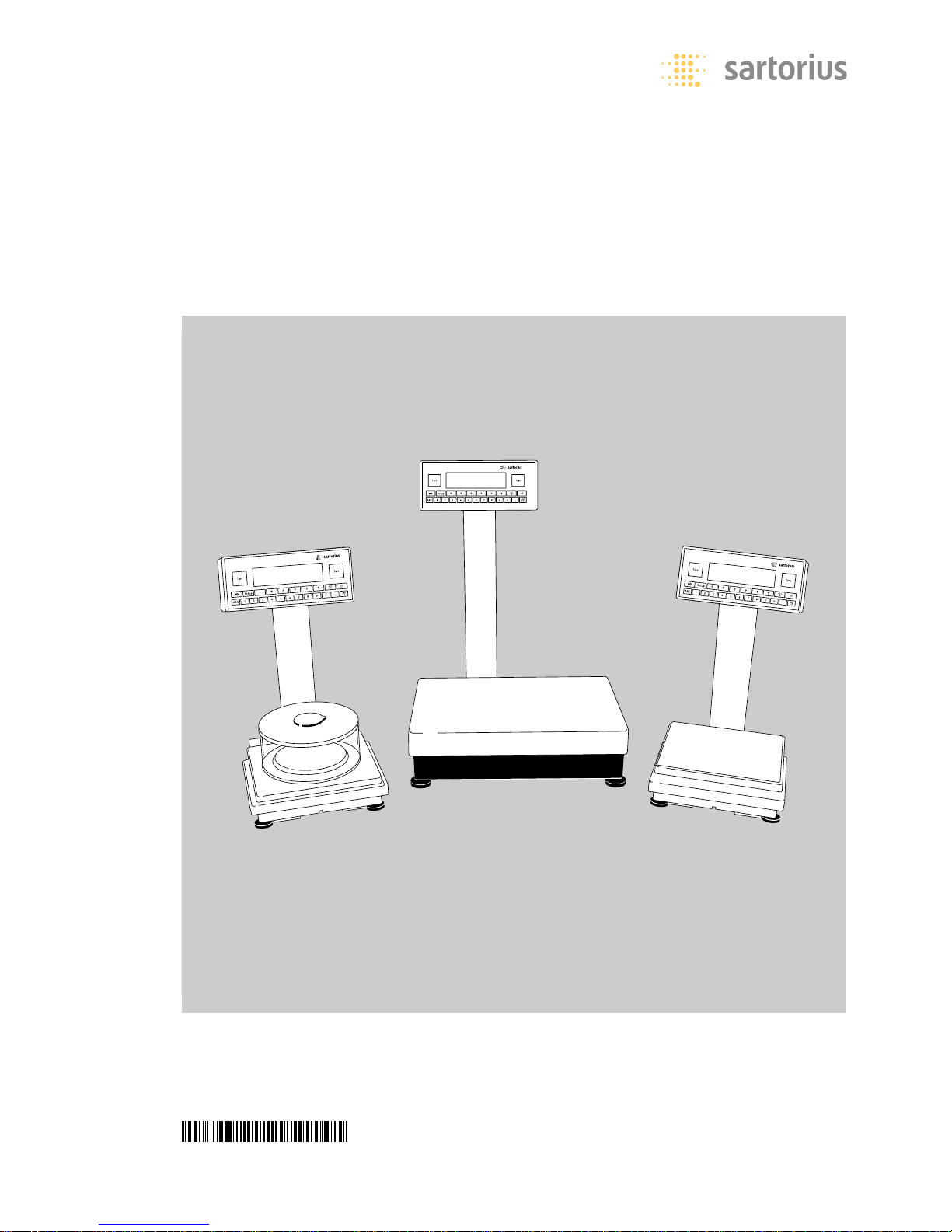
Sartorius Factory Series
FC and FCG Models
Electronic Precision Scales
98648-006-82

Intended Use Contents
The Factory Series from Sartorius offers
precision scales for measuring mass
(weight). The scales in this series have
capacities ranging from 1mg to 64 kg.
A broad range of special performance
features make the Factory scales ideal
for use as inspection, measuring and
test equipment in quality management
systems.
These features include:
– Self-calibrating and adjustment
function, isoTEST
– reproTEST for quick determination of
the standard deviation to check the
reproducibility of results
– ISO/GMP-compliant recording
capability for printouts
– Password-protected menu lock
Factory scales meet the highest requirements on the accuracy and reliability of
weighing results through the following
features:
– Efficient filtering-out of interference
from ambient conditions, e.g.
vibrations, drafts, etc.
– Stable and reproducible results
– Excellent readability under any lighting
conditions
– Rugged, durable weighing system
Factory scales save work and speed up
simple routine applications through:
– Ultrafast response times
– Built-in application programs, including
Application 1:
– Toggling between two weight units
– Counting
– Weighing in percent
– Animal weighing
– Recalculation
– Calculation
Application 2:
– Checkweighing
– Time-controlled functions
Application 3:
– Totalizing
– Formulation
– Statistics
with the following additional functions:
– Second tare memory
– Identifier
– Product data memory
– Manual data storage in Application 3
– Automatic initialization when you
switch on the scale
– Easy input of alphanumeric sample,
lot and scale IDs
– Flexible, easy-to-use display and
control unit
– Connectivity for control through an
on-line computer
Hotline
For advice on the use of these
applications, just call or fax
Your local Sartorius office for the
address, please visit our Internet
website www.sartorius.com.
2 Intended Use
2 Contents
3 Warning and Safety Information
3 Operating Design
7 Getting Started
14 Configuration
14 Setting the Language
15 Navigating in the Setup Menu
16 Setting Date and Time
17 Setting the Scale Functions
20 Setting the Device Parameters
24 Setting the Application Parameters
30 Selecting the Printout Function
32 Printout Configuration
35 Displaying Info
36 MP8 Interface Emulation
38 Operation
38 Basic Weighing Function
43 Calibration and Adjustment
52 ReproTEST
53 Application Programs
53 Toggle between Two Weight Units
55 Counting
58 Weighing in Percent
61 Animal Weighing
65 Recalculation
70 Calculation
72 Checkweighing
77 Time-Controlled Functions
79 Totalizing
83 Formulation
87 Statistics
91 Additional Functions
(Application Menu)
93 Individual Identification Codes (ID)
97 Saving Values Manually (M+)
98 Product Data Memory
100 “FlexPrint” Printout Function
101 Combining Applications
102 Examples of Application
Combinations
104 Data Output Functions
106 Printouts
108 Interface Description
113 Pin Assignment Chart
116 Error Codes
118 Care and Maintenance
118 Instructions for Recycling
119 Overview
119 General Views of the Scales
122 Specifications
126 Dimensions (Scale Drawings)
128 Accessories (Options)
131 Declarations of Conformity
133 EC Type Approval
135 Plates and Markings
136 Index
Appendix
Entering the General Password
2
Warning and Safety Operating Design
Information
This scale has been constructed in
accordance with the European Directives
as well as international regulations and
standards for operation of electrical
equipment, electromagnetic compatibility, and stipulated safety requirements.
Improper use or handling, however, can
result in damage and/or injury.
Read these operating instructions
thoroughly before using your scale to
prevent damage to the equipment.
Keep these instructions in a safe place.
Follow the instructions below to
ensure safe and trouble-free operation
of your scale:
! Do not use this scale in a hazardous
area/location
! Make sure that the voltage rating
printed on the AC adapter is identical
to your local line voltage
– The only way to switch the power
off completely is to disconnect the
AC adapter
– The scale housing is protected as listed
below against dust deposits and water
splashes – the housing is not completely
dust-tight, however.
– IP 44 for FCG64EDE-H
– IP 65 for all other FC…EDE models
– IP 54 for models with a weighing
capacity <12 kg
– Protect the AC adapter from contact
with liquid.
– Connect only Sartorius accessories and
options, as these are optimally designed
for use with your Factory scale.
Do not open the scale housing.
If the seal is broken, this will result
in forfeiture of all claims under the
manufacturer’s warranty.
In case you have any problems with
your scale:
$ contact your local Sartorius office,
dealer or service center
The scales in the Factory Series consist
of a weighing cell and a display and
control unit. In addition to the choice of
power supply (via AC adapter or external
rechargeable battery pack), your scale
also has an interface port for connecting
a printer, computer or universal remote
control switch.
The display and control unit and the
weighing cell can be set up separately.
Operation of Factory scales follows a
uniform “philosophy” which is described in
this manual. Where not expressly indicated
otherwise, the uses described in this manual
apply to verified and verifiable scale
versions (indicated by the suffix “-0CE”
in the model number), as well as the
standard version.
Combination of Several Applications
You can combine the use of various
application programs to meet your more
complicated requirements. To select
application programs one after the other,
press D (toggle function).
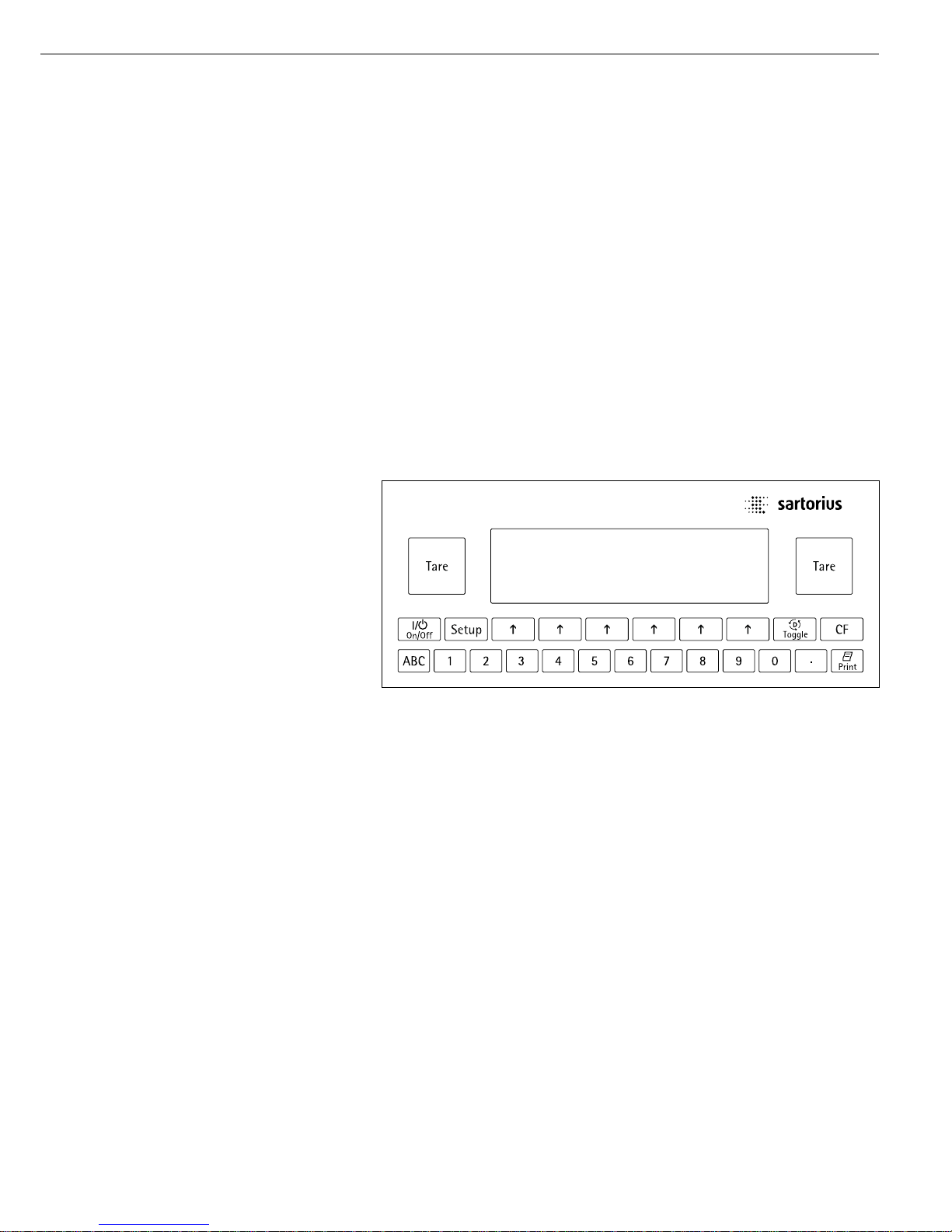
Keys
Your Factory scale is operated either by
using the keys on the display and control
unit or via a connected PC. Operation by
means of the scale keys is described in the
following.
3
Meaning
a Alphabetic keys
Please see section on “Text Input”
e On|off key
Turns the scale on and off or
switches it to the standby mode
H Menu settings
Accesses and exits the Setup menu
D Toggles to the next application
program
c Clear function
Deletes keypad input
Interrupts a calibration and
adjustment routine in progress
Quits application programs
p Print key
Outputs displayed values or data
logs to the serial communications
and|or printer port
. Enters a decimal point
1 ... 9 0 keys
See the section on “Numeric Input”
t Tares the scale
Numeric Input
To enter numbers:
press 1 ... 9 0 .
To store numbers entered: press the
corresponding function key directly
below the soft key label
To delete an entire numeric input
digit by digit: press the c key
Operating Design
Text Input
§ To enter numbers:
see the section on “Numeric Input”
§ To enter letters or characters:
press the a key
> Letters are displayed in the bottom line
for selection
● To select a different letter: press the
corresponding soft key to change the
letter shown
● To select the letter|character shown:
press the corresponding function key
below the soft key label
> The selected letter is shown on the
display
$ Enter the next letter| character, if
desired, as described above
$ To exit the letter input mode
(e.g., if the last character entered is
a letter): press the a key
● To store a word: press the corresponding
function key (soft key), such as
ID
● To delete an input character by
character: press the c key
● To delete user data: enter . or a
space and save
Function Keys (Soft Keys)
The current function of soft keys is
indicated in the bottom line of the
display (footer).
Texts (abbreviations) or symbols can
be displayed.
Texts (Examples)
Cal: Start calibration | adjustment
S ID: Save ID
The function keys are numbered from
right (F1) to left (F6).
Symbols
The bottom line shows the following
symbols:
oo Back to the initial state
(in the Setup menu: exit Setup)
o Go to the higher selection level
O Show sub-items under the active
item
Q Move upward in the input |
output window
q Move downward in the input |
output window
l Set the selected menu parameter
Labeled Keys
These keys always have the function
indicated, but are not available at all
times. Availability of these functions
depends on the current operating status
and menu settings.
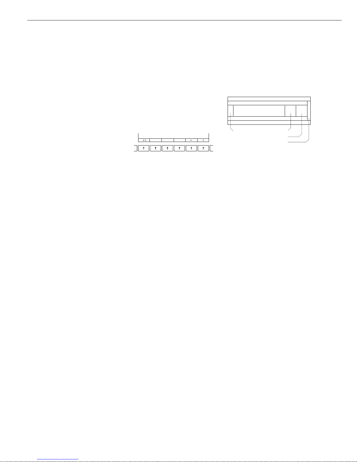
There are two fundamentally different
types of display:
– display for weights and calculated
values
– display for menu parameter settings
(setup)
F6 F5 F4 F3 F2 F1
Operation
Display for Weights and
Calculated Values
This display is subdivided into 9 areas.
Line for Metrological Data:
When the scale is used in legal metrology,
the following metrological specifications
of the scale are shown here:
Max Maximum capacity (upper range
limit) of the scale
Min Minimum capacity (lower
range limit) of the scale
R1 Display when e = d
to
R4
e Verification scale interval
d Readability | scale interval
On standard scale, only
Max and d are
displayed.
Line for metrological data
Bar graph
Measured value line
Text line
Soft key labels
Plus/minus sign Unit
Stability indicator Tare memory
Calculated value
Application pictograms
4
Bar Graph:
The bar graph indicates how much of the
scale’s capacity is “used up” by the current
load; during checkweighing, it indicates
the control limits.
The following symbols may be displayed:
0% Lower load limit
100% Upper load limit
Bar graph showing 10% intervals
- Minimum for checkweighing
= Target for checkweighing
+ Maximum for checkweighing
Plus/Minus Sign, Stability Symbol:
A plus or minus sign (
F or H) is shown
here for a weight (or a calculated value,
such as that for counting), or the
S symbol
indicating that a verified scale has been
zeroed or tared.
Line for Measured Values:
This area shows the weighed or calculated
value and the alphanumeric input.
Note Concerning Verified Scales
Approved for Use as Legal Measuring
Instruments in the EU*:
For verified scales that have a verification
scale interval
e which is greater than
the scale interval
d, the last digit on the
display is bordered.
Unit and Stability:
When the scale reaches stability, the
weight unit or calculated unit is displayed
here.
When the
a symbol is displayed here,
the value indicated in the readout cannot
be used in legal metrology.
* including the Signatories of the Agree-
ment on the European Economic Area
Tare Memory, Calculated Values:
The symbols displayed here indicate
when there is a value in one of the tare
memories or when the value shown is a
result of calculation rather than direct
measurement.
These symbols are as follows:
a Calculated value
s1 Net value | tare memory
s2 used by an application program
(e.g., formulation, second tare
memory)
Application Pictograms:
The pictograms displayed here indicate
the application(s) selected. The pictogram is displayed inversely (white on
a black background) when the corresponding application is active.
For example, the following symbols
may be displayed simultaneously:
A The counting application is active
H Checkweighing is also active
S Print
T Data record
Text Line:
Additional information is displayed here
(e.g., operator guidance prompts, name
of the active program, etc.)
Soft Key Labels:
The current functions of the soft keys
above the function keys (arrow keys)
are indicated here; during calibration |
adjustment, this line shows up- and
down-arrows (
Q and q) for selecting
calibration and adjustment functions.
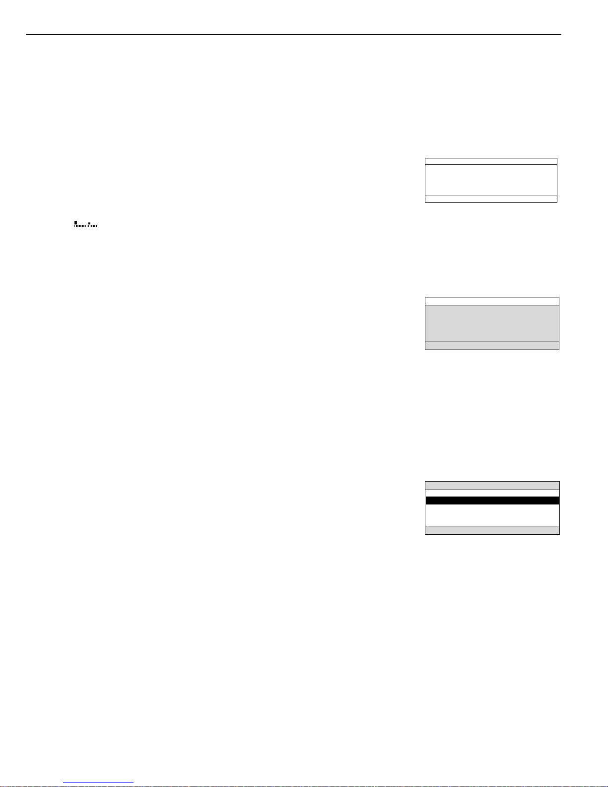
Display for Menu Parameter Settings
(Setup)
This display is divided into three sections.
Status Line:
The status line of shows the function
of the display screen page. In the Setup
menu, the current menu “path” is
shown here.
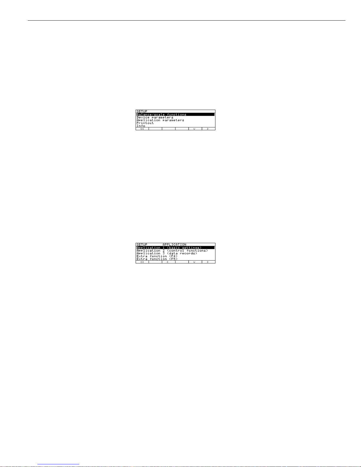
Setup Menu Example: “Balance/scale
functions”:
Input and Output Window
This window contains either detailed
information (e.g., on the active
application) or a pick list. A selected
item is displayed inversely (white
characters on a black background).
You can also enter information in an
active field in this window using the
alphabetic and numeric keys.
Setup Menu Example,
“Device parameters, Adapt filter”:
The following symbol may be displayed
in the input and output window:
d this symbol marks the saved
menu setting
Soft Key Labels
See the description “Function Keys
(Soft Keys)” on the previous page
Minimum vibration
o Normal vibration
Strong vibration
Extreme vibration
SETUP BAL.FUNC.
Line for Operating State
Input and Output Window
Soft key labels
5

Operating Design
To set a parameter:
● Press the
Q or q soft key repeatedly
until the desired setting is selected
(displayed inversely)
● Confirm your selection:
press the
l soft key
To change the numeric value of
a parameter:
● Press the
Q or q soft key repeatedly,
if necessary, until the desired setting is
selected (displayed inversely)
● Enter a new value or character:
use the 0 1 … 9 . keys or the
a key and enter the desired letters
● Confirm your selection:
press the l soft key
To exit Setup: press the oo soft key
Input
Bar Code Scanner or Keyboard Input
You can use a bar code scanner or an
external keyboard to input alphanumeric values. These inputs are processed
in the same manner as keypad inputs
on the display and control unit of the
scale. Bar code and keyboard inputs
are only displayed; they cannot activate
any function.
To assign a bar code scanner or
keyboard input to a function, press one
of the following soft keys:
– Lot
– Samples
– Measured values
– Sample number
– Tare value
– Initial weight
– Backweighed value
– Sample ID
Foot or Hand Switch Input
You can connect a foot switch or a
hand switch to the scale to have this
device perform a keypad function
(such as c or t).
PC Input
You can use a computer to control
the functions of the weighing cell and
display and control unit via the communications port (see the “Data Output
Function” section in the chapter
entitled “Operation”).
Data Output
Your Factory scale is equipped with
an interface port for connecting your
choice of the following:
– Printer
– Peripheral device (e.g., computer)
– Universal remote control switch
Printer
You can configure the print functions
to meet your individual requirements by
selecting the corresponding menu code.
You can have printouts generated
automatically, or by pressing p;
dependent on or independent of the
stability or time parameters; with or
without IDs; and as standard or
ISO/GMP-compliant printouts.
ISO: International Organization for
Standardization
GMP: Good Manufacturing Practice
See the section on “Data Output
Functions” in the chapter entitled
“Operation” for a detailed description
of data output options.
Interface Port
Instead of a printer, you may choose
to connect a different peripheral device,
e.g. a computer (PC). With an on-line
PC you can control both the weighing
cell and the display unit of the Factory
scale.
Request messages are sent via the
interface to initiate functions in the
weighing cell and in the display unit.
Some of the functions generate
response messages.
See the chapter entitled “Operation”
under the section on “Data Output” for
a detailed description of the interface
port.
Error Codes
If you press a key that has no function,
or which is blocked at a certain point
in an application program, this error is
indicated as follows:
– a double-beep is sounded as an
acoustic signal if the key has no
function
– a double-beep is sounded and a
message is displayed for 2 seconds
in
the text line if the key function is not
available at that time
The response to an operator error is
identical in all models of the Factory
series. See the chapter entitled “Error
Codes” for a detailed description.
Storing Settings
Storing Parameter Settings
The settings configured are stored
in the scale’s non-volatile memory. The
most recent parameter settings are
active when you switch on the scale.
Saving Parameter Settings
You can assign passwords in order to
block access to:
– Weighing parameters
– Device parameters
– Application parameters
– Factory settings
6

Getting Started
Storage and Shipping Conditions
– Do not expose the scale to extreme
temperatures, jolts, impacts, vibration
or moisture.
Unpacking the Scale
● After unpacking the scale, check it
immediately for any visible damage as
a result of rough handling during
shipment.
$ If any damage is visible, proceed as
directed in the chapter entitled “Care
and Maintenance,” under the section
on “Safety Inspection.”
It is a good idea to save the box and
all parts of the packaging until you have
successfully installed your scale
. Only
the original packaging
provides the best
protection for shipment. Before packing
your scale, unplug all connected cables
to prevent damage.
Important Note Concerning Verified
Scales Approved for Use as Legal
Measuring Instruments in the EU*:
Provided that an official seal is required
for the verified scale, a control seal is
affixed to the scale. This seal will be
irreparably damaged if you attempt
remove it. If the seal is broken, the
validity of the verification will become
void and you must have your scale
re-verified.
* including the Signatories of the Agree-
ment on the European Economic Area
Equipment Supplied
The equipment supplied includes the
components listed below:
FC06BBE-S
– Complete scale with data interface port
– AC adapter
– Column for display and control unit
– Retainer
– Dust cover
– Shield ring
– Load plate support
– Load plate
– Glass cylinder/draft shield
– Draft shield cover
FC6CCE-H, FC2CCE-S
– Complete scale with data interface port
– AC adapter
– Column for display and control unit
– Retainer
– Dust cover
– Load plate shield
– Load plate
FC12CCE-S, FC6CCE-S
– Complete scale with data interface port
– AC adapter
– Column for display and control unit
– Retainer
– Dust cover
– Load plate
FCG34EDE-H, FCG34EDE-P,
FCG16EDE-H, FCG12EDE-P,
FCG64EDE-S, FCG64EDE-H
– Complete scale with data interface port
– AC adapter
– Column for display and control unit
– Retainer
– Load plate
Installation Instructions
When choosing a location to set up
your scale, observe the following so
that you will be able to work with
added speed and accuracy:
– Avoid placing the scale in close prox-
imity to a heater or otherwise exposing
the scale to heat or direct sunlight
– Protect the scale from drafts hat come
from open windows or doors
– Do not expose the scale to extreme
moisture over long periods
– Avoid exposing the scale to extreme
vibrations during weighing
– Set up the scale on a stable, even
surface
– Protect the scale from aggressive
chemical vapors
Conditioning the Scale
Moisture in the air can condense on
the surfaces of a cold scale whenever it
is brought into a substantially warmer
place. If you transfer the scale to a
warmer area, make sure to condition it
for about 2 hours at room temperature,
leaving it unplugged from AC power.
7
Getting Started
Mounting the Display and Control Unit
You can mount the display and control unit in one of 3 ways:
– on the column, which is then fastened to the back of the scale
– on the retainer, which is then fastened to the front of the scale
– on the retainer separately from the scale
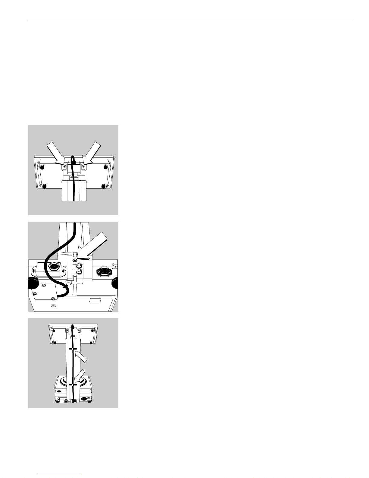
FC06BBE-S, FC6CCE-H, FC2CCE-S, FC12CCE-S, FC6CCE-S
Mounting the Control Unit and Column
§ Fasten the display unit to the retainer using the two Phillips head screws supplied
§ Fasten the column to the scale using the screws supplied
§ Press the cable into the two clamps on the back of the column and then press it into
the channel (raceway) on the bottom of the scale
8
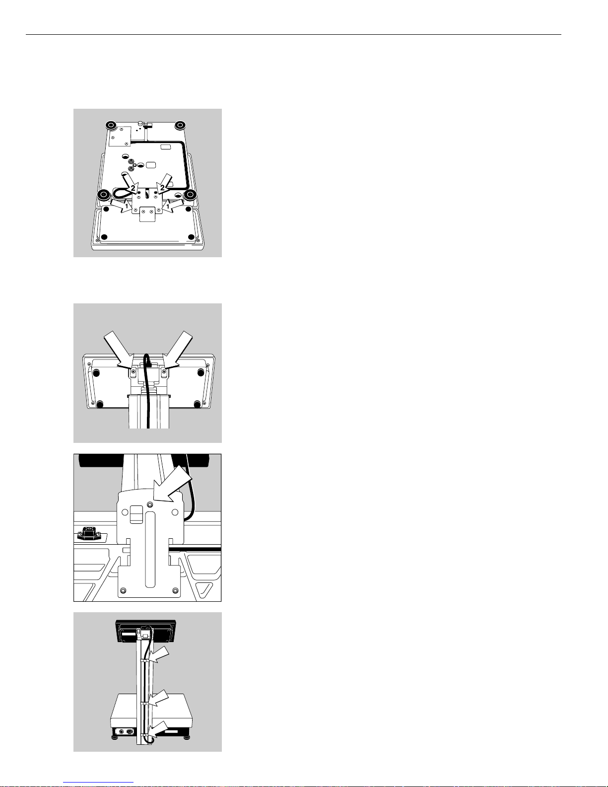
Fastening the Display and Control Unit to the Front of the Weighing Platform
or Mounting It Separately
§ Turn the scale over and place it on a cushioned surface to prevent damage to the
weighing system
§ Fasten the retainer to the display and control unit using the two Phillips head
screws 1 (M4x12)
§ Fastening the display and control unit to the weighing platform: Fasten the retainer
with the two Phillips head screws 2 (M4+12) to the weighing platform
§ Press the cable into the raceway (channel) as shown in the diagram on the left
> Cable length: 55 cm (21.7 inches)
$ To order a longer cable, see the section entitled “Accessories”
FCG34EDE-H, FCG34EDE-P, FCG16EDE-S, FCG12EDE-P,
FCG64EDE-S, FCG64EDE-H
Installing the Display and Control Unit on the Column
§ Use the two Phillips head screws (M 4+8) supplied to fasten the display and
control unit to the column
§ Attach the column to the scale using the screw (M 4+ 20)
§ Fasten the connecting cable to the column using the three clips
9
Getting Started
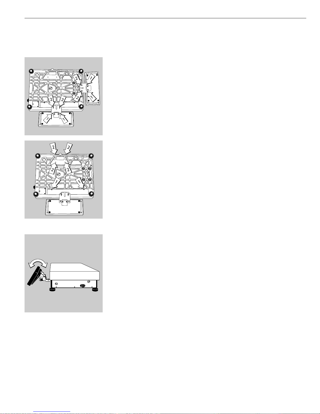
Fastening the Display and Control Unit to the Front of the Weighing Platform
§ Turn the scale over and place it on a cushioned surface to prevent damage to the
weighing system
§ Remove the column retainer from the scale
§ Fasten the display and control unit retainer to the display and control unit using
the 2 Phillips head screws supplied (1) (M4+8)
§ Fastening the retainer to the scale: Fasten the retainer to the scale using the
Phillips head screws supplied (2) (M4+ 8)
§ Press the cable into the raceway (channel)
§ Replace the cover on the cable raceway (1)
§ Close the 4 bore holes using the caps supplied (2)
Remote Operation of the Display and Control Unit
§ Turn the scale over and place it on a cushioned surface to prevent damage to the weighing system
§ Remove the column retainer from the scale
§ Close the 4 bore holes using the caps supplied (2)
> Cable length: at least 80 cm (approximately 31 inches)
§ To order a longer cable, see the section entitled “Accessories”
Adjusting the Angle of the Display and Control Unit (only with Accessory YDH01F)
§ Tilt the display and control unit to the desired position and tighten the knurled thumb
screw to hold it in place.
10
Installing the Components
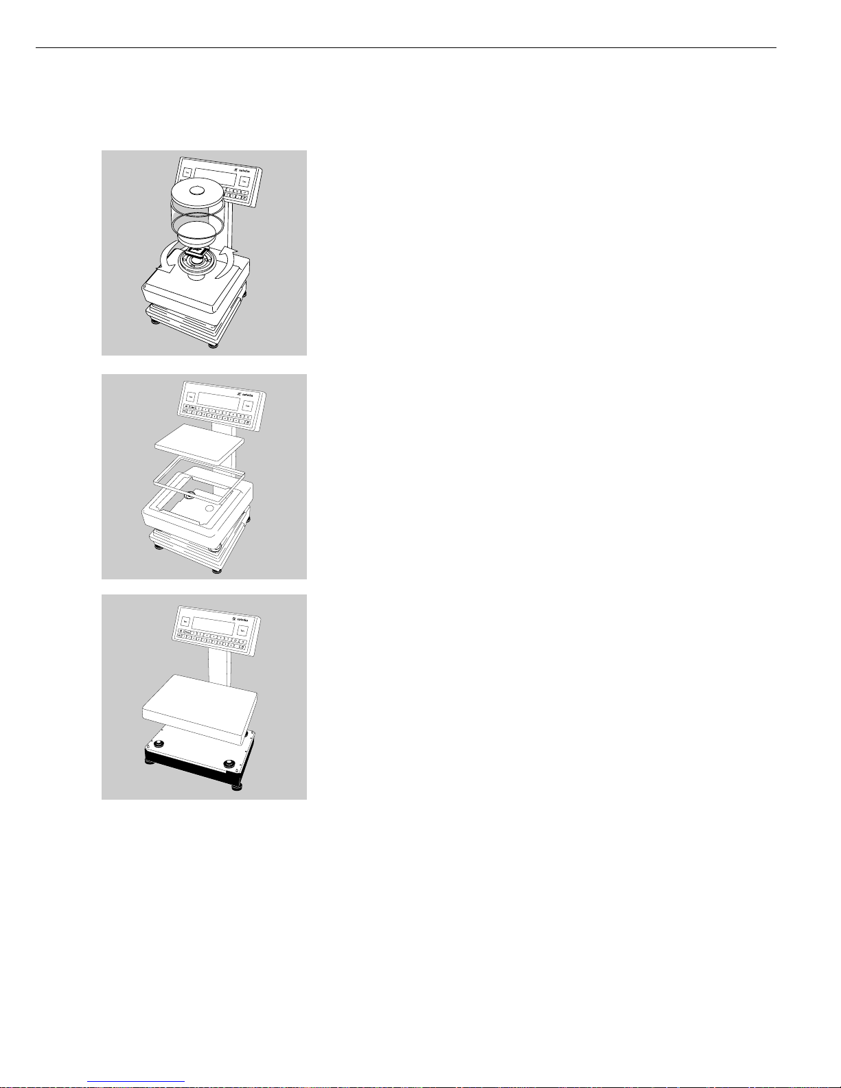
FC06BBE-S
§ Place the following components on the scale in the order given below:
– Dust cover
– Place the shield ring on the scale and turn it counterclockwise until it
is securely positioned in place
– Load plate support
– Load plate
– Glass cylinder
– Draft shield cover
FC6CCE-H, FC2CCE-S, FC12CCE-S, FC6CCE-S
§ Place the following components on the scale in the order given below:
– Dust cover (remove backing from the adhesive surface)
– Load plate shield (depends on the type of model)
– Load plate
FCG34EDE-H, FCG34EDE-P, FCG16EDE-S, FCG12EDE-P, FCG64EDE-S, FCG64EDE-H
§ Position the load plate
11
Getting Started
Connecting the Scale to AC Power
§ Check the voltage rating and the plug design
– If they do not match, contact your Sartorius office or dealer
Use only:
– Original Sartorius AC adapters
– Power supplies approved by a certified or authorized technician
$ To use a main feeder cable from the ceiling or a CEE plug, have this equipment installed
or mounted by an authorized technician in your facilities
$ To use an external rechargeable battery pack, see “Accessories” in the “Overview” section
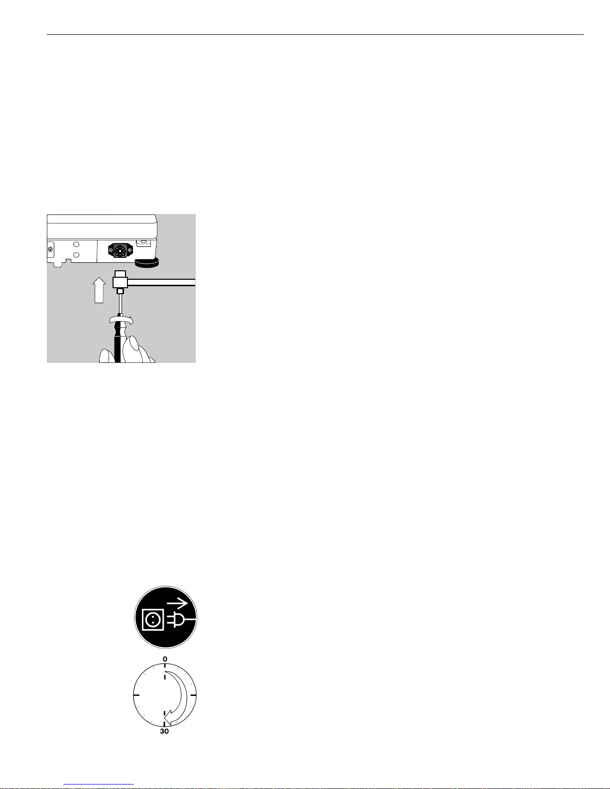
§ Insert the right-angle plug into the jack and use a screwdriver to tighten the
slotted-head screw
§ To energize the scale with AC power:
Plug the AC adapter into a wall outlet (mains)
Information on Radio Frequency Interference
Note:
This equipment has been tested and found to comply with the limits pursuant to part 15
of the FCC Rules. These limits are designed to provide reasonable protection against
harmful interference. This equipment generates, uses and can radiate radio frequency
energy and, if not installed and used in accordance with these instructions, may cause
harmful interference to radio communications.
For information on the specific limits and class of this equipment, please refer to the
Declaration of Conformity. Depending on the particular class, you are either required or
requested to correct the interference.
If you have a Class A digital device, you need to comply with the FCC statement as
follows: “Operation of this equipment in a residential area is likely to cause harmful
interference in which case the user will be required to correct the interference at his
own expense.”
If you have a Class B digital device, please read and follow the FCC information given
below:
However, there is no guarantee that interference will not occur in a particular installation.
If this equipment does cause harmful interference to radio or television reception, which
can be determined by turning the equipment off and on, the user is encouraged to try to
correct the interference by one or more of the following measures:
- Reorient or relocate the receiving antenna.
– Increase the separation between the equipment and receiver.
– Connect the equipment into an outlet on a circuit different from that to which the receiv-
er is connected.
– Consult the dealer or an experienced radio/TV technician for help.
Before you operate this equipment, check which FCC class (Class A or Class B) it has
according to the Declaration of Conformity included. Be sure to observe the information
of this Declaration.
Safety Precautions
The AC adapter rated to Class 2 can be plugged into any wall outlet without requiring
any additional safety precautions. The ground or earth terminal is connected to the
scale housing, which can be additionally grounded, if required. The data interface is
also electrically connected to the scale housing (ground).
Connecting Electronic Peripheral Devices
§ Make absolutely sure to unplug the scale from AC power before you connect or
disconnect a peripheral device (printer or PC) to or from the interface port
Warmup Time
To deliver exact results, the scale must warm up for at least 30 minutes after initial
connection to AC power or after a relatively long power outage. Only after this time
will the scale have reached the required operating temperature.
Using Verified Scales as Legal Measuring Instruments in the EU*:
$ Make sure to allow the scale to warm up for at least 24 hours after initial connection
to AC power or after a relatively long power outage
* including the Signatories of the Agreement on the European Economic Area
12
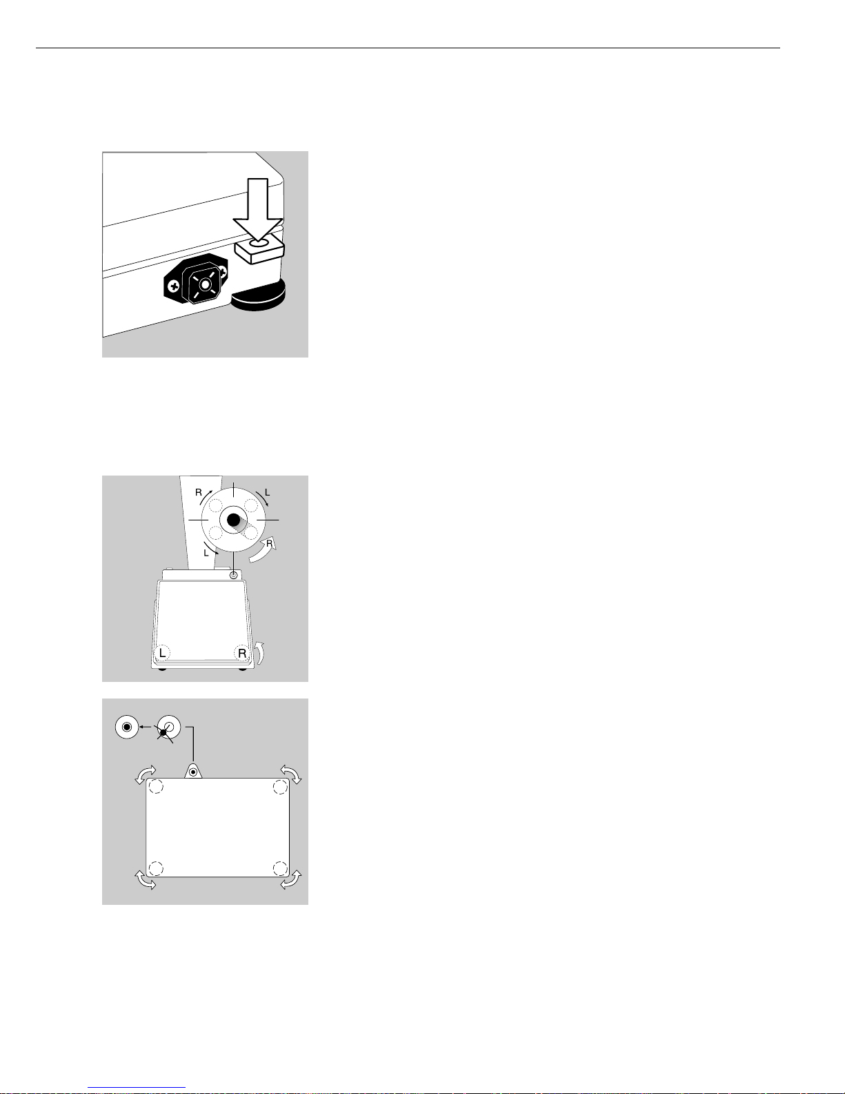
Fastening an Antitheft Locking Device
$ Models FC06BBE-S, FC6CCE-H, FC2CCE-S, FC12CCE-S, and FC6CCE-S only.
To fasten an antitheft locking device, use the lug located on the rear panel of the scale.
§ Secure the scale at the place of installation, e.g., with a chain or a lock.
Leveling the Scale
Purpose:
– To compensate for unevenness at the place of installation
– To achieve perfectly horizontal positioning of the scale for consistent reproducibility
of results
Always level the scale again any time it is moved.
Leveling Scales FC06BBE-S, FC6CCE-H, FC2CCE-S, FC12CCE-S, and FC6CCE-S
Only the 2 front feet are used for leveling.
§ Turn the 2 front feet as shown in the illustration until the air bubble is centered
within the circle of the level indicator
> Several leveling steps are usually required.
§ Extend the two rear feet until they touch the surface on which the scale rests
Leveling Scales FCG34EDE-H, FCG34EDE-P, FCG16EDE-S, FCG12EDE-P,
FCG64EDE-S, FCG64EDE-H
§ Adjust the four leveling feet until the air bubble is centered within the circle of
the level indicator
Setting the Language
> See the “Setting the Language” section in the chapter entitled “Configuration”
Setting the Date and Time
> See the “Entering User Data” section in the chapter entitled “Configuration”
13
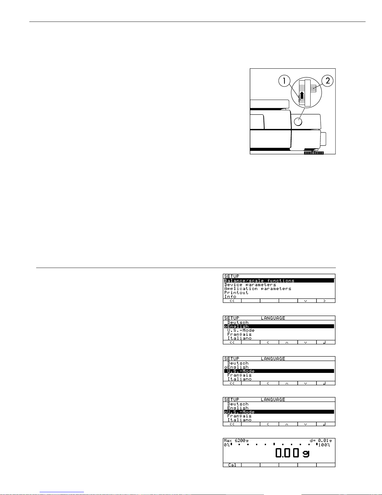
Example: Setting the Language to “U.S. Mode”
Step Press key (or follow instructions) Display/Output
1. Select “Setup” menu H
2. Select “Language” Repeatedly
and confirm press
q soft key,
then
O soft key
3. Select “U.S. mode”
q soft key twice
4. Save language
l soft key
5. Exit the Setup menu
oo soft key
Configuration
Purpose
You can configure the scale to meet
individual requirements by entering user
data and setting parameters in the Setup
program.
The Setup menu contains the following
submenus:
– Scale functions
– Device parameters
– Application parameters
– Printout functions
– Device information
– Language
– Factory settings
Setting the Language
You can choose from 5 languages for
the information display:
– German
– English (factory setting)
– English with U.S. date | time format
– French
– Italian
– Spanish
Configuring the Scale for Use
in Legal Metrology
Set the menu access switch as described
below to configure the following
functions for use of the scale in legal
metrology:
– Display: Verification scale interval:
e;
lower limit of the weighing capacity:
Min
– External calibration blocked
– Block MP8 interface emulation
Preparation:
● Remove the cap from the back of the
scale housing
● Move the switch (1) upwards
> When the switch is in the upper posi-
tion, the Setup menu is locked and the
scale can be used in legal metrology
When the switch is in the lower
position, the menu is accessible
> Note:
Do not move Switch 2
14
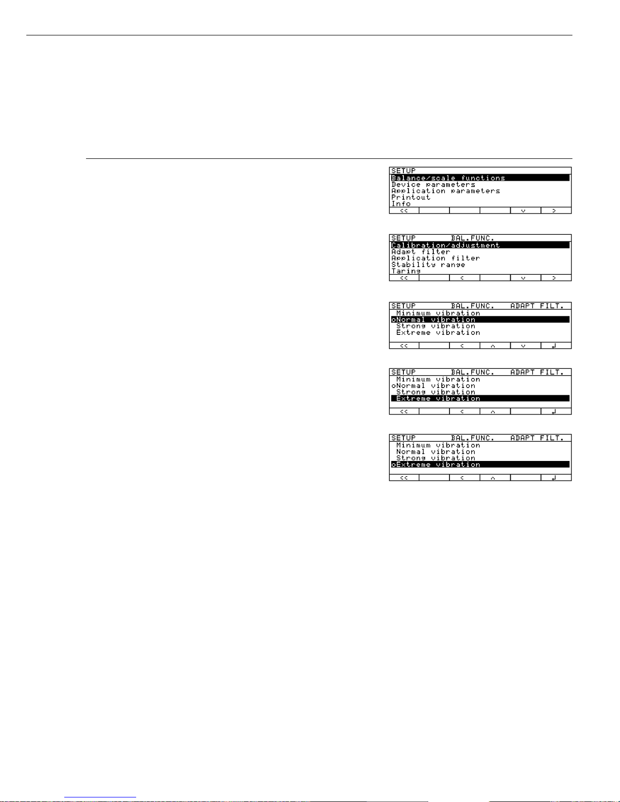
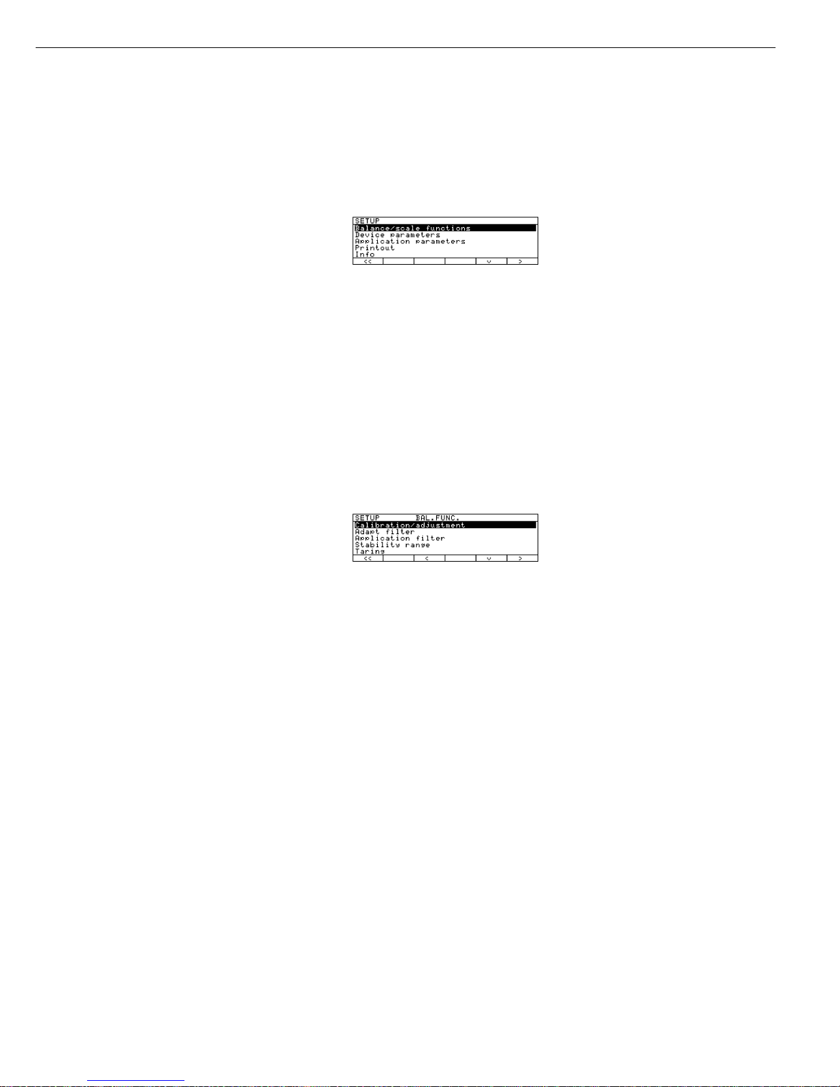
Navigating in the Setup Menu (Examples)
Example: Adapting the scale to “Extreme vibration”
Step Press key(s)
(or follow instructions) Display/Output
1. Select Setup menu H
2. Confirm “Balance/scale functions” O soft key
3. Select menu item “Adapt filter” q, then
and confirm O soft key
4. Select menu item “Extreme vibration” q soft key
5. Confirm menu item “Extreme vibration” l soft key
6. If required, select further menu items oqQO soft keys
7. Save setting and exit Setup Menu oo soft key
15
Configuration
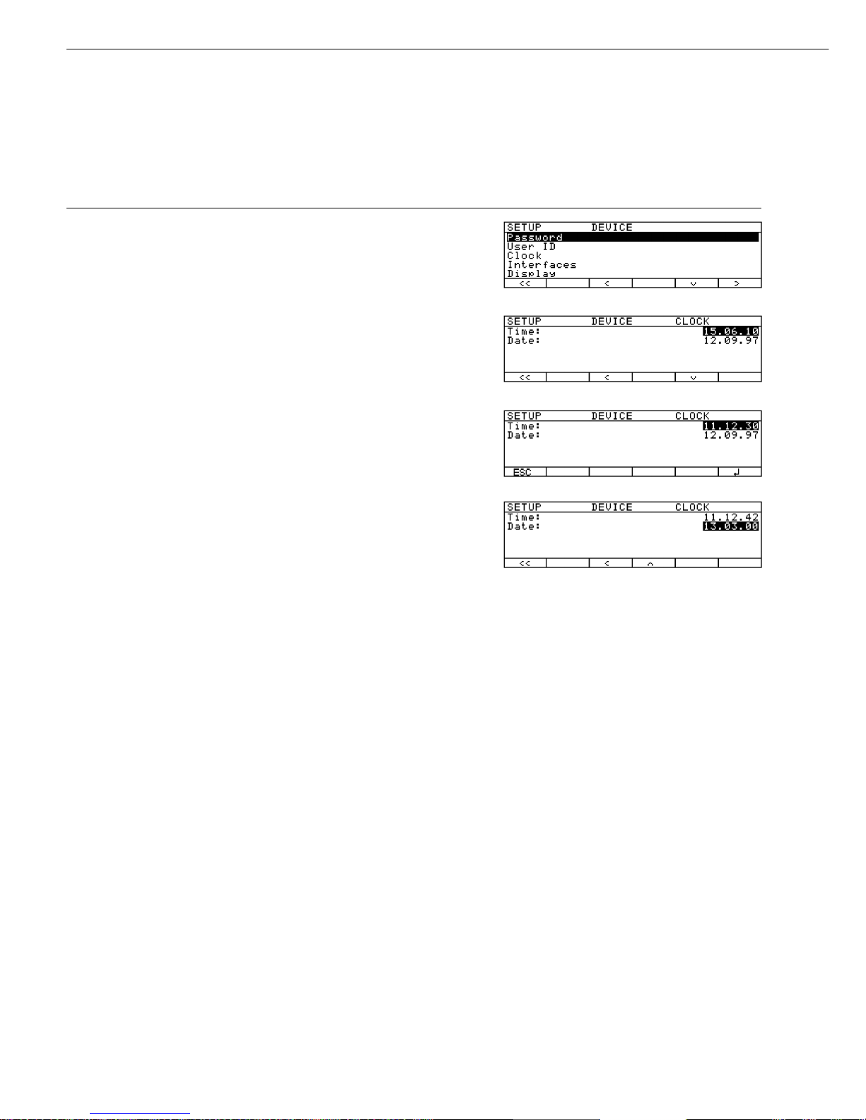
Example: Setting date and time
Step Press key(s)
(or follow instructions) Display/Output
1. Select Setup menu; H, then
select “Device parameters” q soft key and O soft key
2. Select “Clock” press q repeatedly,
then press O
3. Enter the time 1 1 . 1 2
. 3 0
4. Confirm the time entered when it
synchronizes with your local clock l soft key
5. Enter the date 1 3 . 0 3
. 0 0
6. Store the date l soft key
7. Enter other data, if desired oqQO soft keys
8. Exit Setup menu oo soft key
16
Setting the Scale Functions (BAL.FUNC.)
Purpose
This menu item enables you to
configure the scale functions, i.e.,
to meet individual requirements by
selecting predefined parameters in the
Setup menu. You can block access
to the menu by assigning a password.
Features
The scale functions are combined in
the following groups (1st menu level):
– Calibration/adjustment
– Adapt filter
– Application filter
– Stability range
– Taring
– Auto zero
– Weight unit 1
– Zero range
– Zero range at power on
– Tare/zero at power on
– Factory settings: only wgh. param.
(only the scale functions)
Factory Settings
Parameters: The factory settings are
identified by the symbol “ο” in the list
starting on the next page.
Preparation
Show available scale functions:
§ Select Setup menu: press the H key
> SETUP is displayed
§ Select “Balance/scale functions":
press the
O soft key
If you already assigned a password:
> The password prompt is displayed
$ If access is blocked by a password:
enter the password using the numeric/
alphabetic keys.
$ If the last character of the password is a
letter: conclude input by pressing a
§ Confirm your password and have
the scale functions displayed:
Press the
l soft key
> Scale functions are displayed:
$ To select the next group:
press the q soft key (down arrow)
$ To select the previous item of a group:
press the
Q soft key (up arrow)
$ To select the next sub-item within
a group: press the
O soft key
(right arrow)
$ To select the previous group:
press the
o soft key (left arrow)
$ To confirm: press the
l soft key
Extra Functions
§ Exit the Setup menu:
press the
oo soft key
> Restart your application
§ Print parameter settings:
– When the balance/scale functions are
displayed, press p
> Printout (example)
Texts with more than 20 characters
are cut off
SETUP
BAL.FUNC.
--------------------Calibration/adjustm
CAL/iso TST key fun
Internal cal./adju
Cal/adjustm seq
Cal. with adjustm au
.
isoCAL-function
Off
Start autom. adjus
isoCAL
Print GLP/GMP adju
Automatic if GLP is
selected
Parameter for exte
Wt. ID (W ID):
Cal./adjust.-wt:
5000.00 g
Adapt filter
Normal vibration
Application filter
Filling mode
Stability range
2 digits
Taring
After stability
Auto zero
Off
Weight unit 1
Grams /g
etc.
17
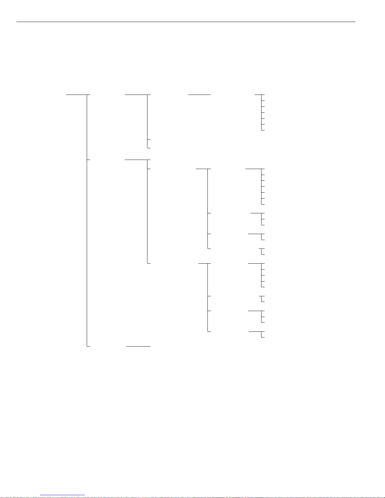
Setting the Scale Functions (Overview)
Setup - Calibration / Cal/isoTST key function External calibration/adjustment**;
Scale adjustment with factory-defined calibration weight
functions External calibration/adjustment**; user-defined weight
ο Internal calibration/adjustment
Cal key blocked
reproTEST
Selection mode for cal./adjustment)
Calibration/ Calibrate, then auto adjust
adjustment sequence ο Calibrate, then manual adjust
isoCAL function ο Off
Only adjustment prompt
On; delete application
On; do not delete application
Start autom. User def. times* Time 1: (hh.mm)
calibration/adjustment Time 2: (hh.mm)
Time 3: (hh.mm)
ο isoCAL
Print GLP/GMP ο Automatic if GLP is selected
adjustment record On request,
from record memory
Parameter for Weight set ID (W ID): Enter 14 characters max.
external weight Calibration/
adjustment-weight: Enter exact weight
Adapt filter Minimum vibration (ambient conditions)
ο Normal vibration
Strong vibration
Extreme vibration
Application filter ο Final readout
Filling mode
Low filtering
Without filtering
Stability range 4 digit
1 digit
1 digit
ο 2 digits
4 digits
8 digits*
Taring* Without stability
ο After stability
Auto zero ο On
Off
** = not applicable to verified scales used in legal metrology in the European Economic Area
** = verified scales can only be externally calibrated, not adjusted (you can only check the external weight)
18
Factory setting
Factory setting

Setup – Weight unit 1* ο Grams /g**
Scale ο Kilograms /kg**
functions Carats /ct*
Pounds /lb*
Ounces /oz*
Troy ounces /ozt*
Hong Kong taels /tlh*
Singapore taels /tls*
Taiwanese taels /tlt*
Grains /GN*
Pennyweights /dwt*
Milligrams /mg*
Parts per pound //lb*
Chinese taels /tlc*
Momme /mom*
Austrian carats /K*
Tola /tol*
Baht /bat*
Mesghal /MS*
Zero range 1 percent/max. capacity
ο 2 percent/max. capacity
Zero range at ο Factory setting (depends on model)
power on 2 percent/max. capacity
5 percent/max. capacity
Tare/zero at ο On
power on* Off
Factory settings: No
only weighing Yes
parameters
** = not applicable to verified scales used in legal metrology in the European Economic Area
** = factory setting depends on weighing range: – < 33 kg: grams
– > 34 kg: kilograms
19
Factory setting
Setting the Device Parameters (DEVICE)
Purpose
This menu item enables you to
configure the scale to meet individual
requirements by selecting predefined
menu parameters in the Setup menu.
You can block access to the menu by
assigning a password.
Features
The device parameters are combined in
the following groups (1st menu level):
– Password
– User ID
– Clock
– Interfaces
– Display
– Keys
– Extra functions
– Factory settings: only device parameters
Factory Settings
Parameters: The factory settings are
identified by the symbol “ο" in the list
starting on the page after next.
Preparation
Display available device parameters
§ Select the Setup menu: press H
> SETUP is displayed:
§ Select “Device parameters”:
use the
q and O soft keys
If no password has been assigned,
anyone can access the Setup menu
device parameters.
If a password has already been
assigned:
> The password prompt is displayed
$ If access is blocked by a password:
enter the password using the numeric
and/or alphabetic keys
$ If the last character of the password
is a letter: conclude input by pressing
the a key
§ Press
l to confirm the password
> Device parameters are now displayed:
$ To select the next group:
press the
q soft key (down arrow)
$ To select the previous menu item of
a group: press
Q soft key (up arrow)
$ To select the next sub-item within
a group: press the
O soft key
(right arrow)
$ To select the previous group:
press the
o soft key (left arrow)
$ Press
l soft key to confirm the
selected menu item
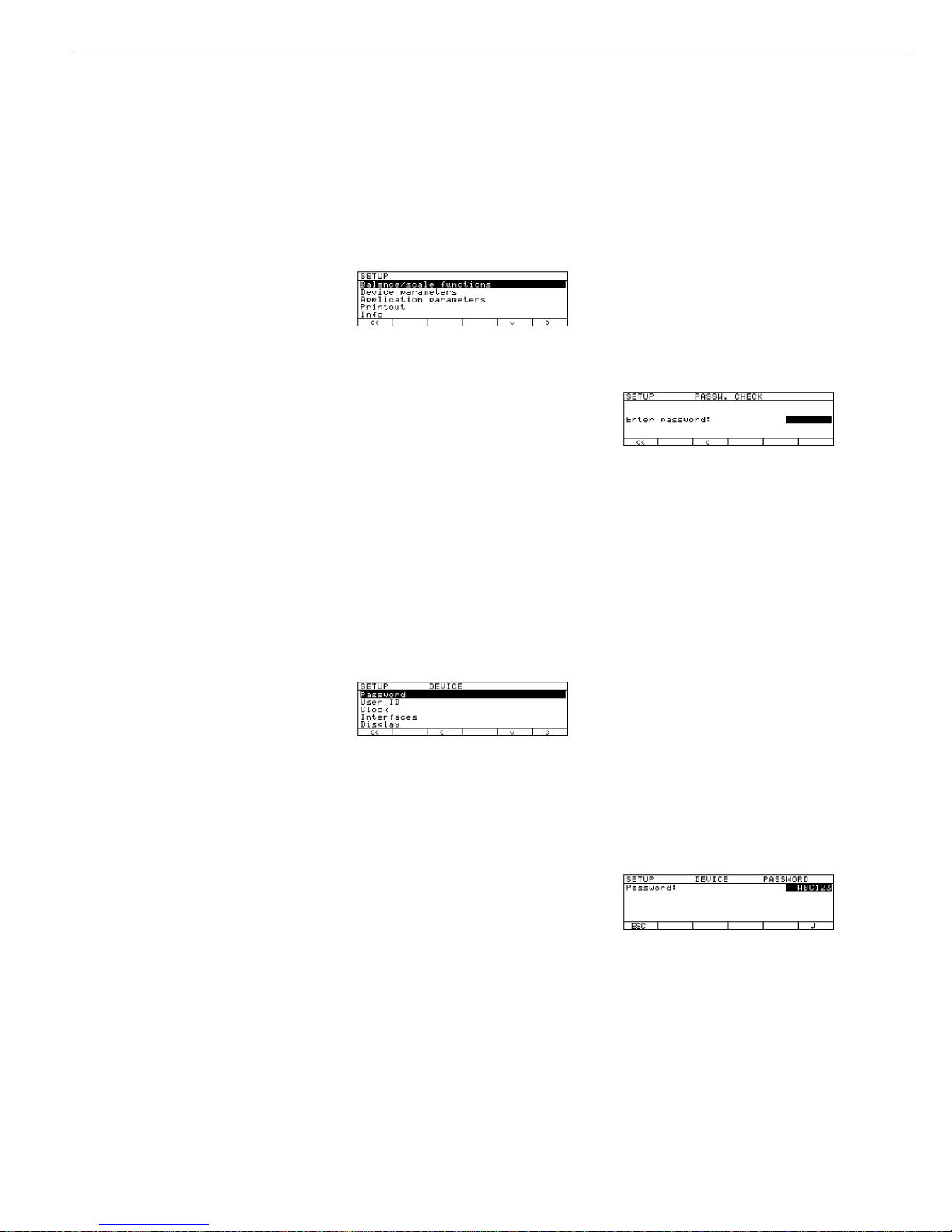
Entering or Changing a Password
– Let’s assume that a password (with
8 characters max.) has already been
assigned to access the Setup device
parameters
§ Select the Setup menu: press H
> SETUP is displayed
§ Select parameters:
Use the
q and O soft keys
> The password prompt is displayed:
$ Enter the password
$ Press the
l soft key to confirm
your password and view the device
parameters
§ Write down your password here for
easy reference:
Password =..............................
If you assign a password and then
forget what the word is:
$ Enter the General Password
(see Appendix)
$ Press the
l soft key to confirm and
display the password
> The parameters are displayed
§ Select the device parameter “Password”:
If necessary, repeatedly press
q or Q ,
until you see
>
Password: and any existing
password
20

§ New password: Enter the numbers
and/or letters for the new password
(8 characters max.)
(If “none" is displayed, this means no
password has been assigned.) To delete
the user password: Press . and
confirm
§ To confirm: press the
l soft key
§ Exit the Setup menu:
press the
oo soft key
> Restart the application
Extra Functions
§ Exit the Setup menu:
press the
oo soft key
> Restart the application
§ Print the parameter settings:
– If the device parameters are displayed:
press p
> Printout (example)
SETUP
DEVICE
--------------------
User ID
User ID:
Interfaces
Serial communicati
SBI
Baud rate
1200 baud
Number of data b
7 data bits
Parity
Odd
Number of stop b
1 stop bit
Handshake-mode
Hardware handshake
after 1 char
Function external
Print key
Function control
Output
Display
Contrast
2
Background
White
Digit size
10mm + bar graph
+text display
Application symbo
On
Keys
CF function in ap
Clear all applicati
CF function for i
Delete last charact
Block key functio
All keys unblocke
etc.
21

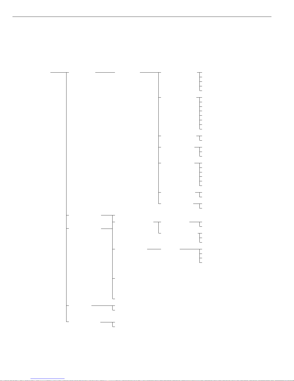
Setting the Device Parameters (DEVICE)
Device Parameters (Overview)
o factory setting
√ user-defined setting
Setup –
Device
parameters
Password: None Enter 8 characters max.
User ID: None Enter 20 characters max.
Clock Time: Enter hh.mm.ss
Date: Enter dd.mm.yy or mm.dd.yy
(01.01.97)
Interfaces Serial ο SBI Baud rate 150 baud
communication 300 baud
(PERIPHERALS) 600 baud
ο 1,200 baud
2,400 baud
4,800 baud
9,600 baud
19,200 baud
Number of ο 7 bit
1)
data bits 8 bit
Parity Space
2)
ο Odd
Even
None
3)
Number of ο 1 stop bit
stop bits 2 stop bits
Handshake Software handshake
mode ο Hardware handshake,
1 character after CTS
xBPI (RS232) Network address: 0 Enter any number from 0 to 31
YDP01IS
YDP02 see YDP03 (without 19,200 baud)
YDP03 Baud rate ο 1,200 baud
2,400 baud
4,800 baud
9,600 baud
19,200 baud
Parity Space
ο Odd
Even
Handshake Software handshake mode
mode ο Hardware-handshake,
1 character after CTS
YDP01IS Label (label printer)
YDP02IS
YDP02IS Label (label printer)
Universal see “SBI” above for submenu items
YDP04IS
YDP04IS Label (label printer)
For the display, keys and extra functions, see next pages
1)
not if “None" parity is selected
2)
only if 7 data bits selected
3)
only if 8 data bits selected
22
Factory setting
Factory setting
Factory setting
Setup –
Device
parameters
Interfaces Function: Print key
external switch ο Tare key
Calibration key
F1 function key
(Right soft key)
Clear function key c
F2 function key
(2nd soft key from the right)
Function: Input
control ports ο Output
Display Contrast Select contrast (0 to 4): 0
1
ο 2
3
4
Background ο White
Black
Backlighting ο On
Auto. off after 4 min. (of non-use)
Digit size ο 10mm + bar graph + text display
13mm + bar graph
13mm + text display
13mm
Application Off
symbols ο On
Keys CF function ο Clear all applications
in application Clear only selected applications
CF function Delete entire input
for input ο Delete last character
Block key ο All keys unblocked
functions All blocked except for H, e
Alphanumeric
keys blocked
Extra functions Acoustic signal ο On
Off
Power-on ο Off/on/standby
mode On/off Automatic After 4 min. (of non-use)
shutoff ο Off
Auto on
Factory settings: No
only Yes
device parameters
23
Factory setting
Factory setting
Setting the Application Parameters (Application)
Purpose
This menu item enables you to
configure the scale, i.e., adapt the scale
to your individual requirements by
selecting from a list of parameter
options in a menu. You can block
access to this menu by assigning a
password.
Features
The simple weighing function is
available at all times. You can select
one from each of the following
application groups. This means a
number of combinations are possible.
Application 1 (basic settings)
– Toggle weight units
– Counting
– Weighing in percent
– Animal weighing (averaging)
– Recalculation
– Calculation
– Density determination
– Differential weighing
Application 2 (control functions)
– Checkweighing
– Time-controlled functions
Application 3 (data records)
– Totalizing
– Formulation
– Statistics
In addition, you can assign 2 extra
functions to each of the soft keys, in
some cases (depending on the Setup
configuration):
– Second tare memory
– Identification codes
– Manual storage M+ key
– Product data memory
Auto-start application the scale
is switched on
Factory settings:
only application parameters
Factory Settings
The factory settings are identified by
the symbol “ο" in the list starting on
the next page.
Preparation
Display available application
parameters:
§ Select the Setup menu:
press the H key
> SETUP is displayed
§ Select parameters: repeatedly press
the
q and O soft keys
If you have already assigned a
password:
> The password prompt is displayed:
$ If access is blocked by a password:
enter the password using the numeric/
alphabetic keys
$ If the last character of the password is a
letter: conclude input by pressing a
§ Confirm your password and have the
application parameters displayed:
press the
l soft key
> The application menu is displayed:
$ To select the next group:
press the q soft key (down arrow)
$ To select the previous item of a group:
press the
Q soft key (up arrow)
$ To select the next sub-item within
a group: press the
O soft key
(right arrow)
$ To select the previous group:
press the
o soft key (left arrow)
$ To confirm: press the
l soft key
Extra Functions
§ Exit the Setup menu:
press the
oo soft key
> Restart your application
§ Print parameter settings:
– When the scale functions are displayed,
press p
> Printout (example)
Texts with more than 20 characters are
truncated
Application 1
-------------------Counting
Average piece weigh
Display accuracy
Average piece weigh
Automatic
Application 2
-------------------Checkweighing
Activation of port
Within Checkweighi
Type of Checkweighi
Target, minimum, m
Weight display mode
Absolute value
Automatic printout
No
Application 3
-------------------Totalizing
etc.
24
Application Parameters (Overview)
ο factory settings
√ user-defined setting
Setup – Application 1 Off (weighing only)
Application (Basic settings) Toggle wt. units Weight unit 1 ο Grams /g**
parameters Kilograms /kg**
Carats /ct*
Pounds /lb*
Ounces /oz*
Troy ounces /ozt*
Hong Kong taels /tlh*
Singapore taels /tls*
Taiwanese taels /tlt*
Grains /GN*
Pennyweights /dwt*
Milligrams /mg*
Parts per pound //lb*
Chinese taels /tlc*
Momme /mom*
Austrian carats /K*
Tola /tol*
Baht /bat*
Mesghal /MS*
Weight unit 2 ο Grams /g**
Kilograms /kg**
Carat s/ct*
Pounds /lb*
Ounces /oz*
Troy ounces /ozt*
Hong Kong taels /tlh*
Singapore taels /tls*
Taiwanese taels /tlt*
Grains /GN*
Pennyweights /dwt*
Milligrams /mg*
Parts per pound //lb*
Chinese taels /tlc*
Momme /mom*
Austrian carats /K*
Tola /tol*
Baht /bat*
Mesghal /MS*
For counting through differential weighing see the following pages
Applications 2 and 3 see following pages
** = not applicable to verified scales used in the European Economic Area
** = factory setting depends on weighing range: – < 33 kg: grams
– > 34 kg: kilograms
25
Factory setting
Setting the Application Parameters (Application)
Setup – Application 1 ο Counting Accuracy – Average ο Display accuracy
Application (Basic settings) piece weight calcu- + 1 decimal place
parameters lation (resolution) + 2 decimal places
Average piece Off
weight updating Manual
ο Automatic
Percent weighing Weight storage ο Display accuracy
(resolution) accuracy + 1 decimal place
+ 2 decimal places
Decimal places for None
readout in percent 1 decimal place
ο 2 decimal places
3 decimal places
4 decimal places
5 decimal places
6 decimal places
Display calculated ο Residue
value Loss
Ratio 1 (DR)
Ratio 2 (OR)
Animal weighing Animal activity Calm
(averaging) Normal
Active
0.1% of the animal/object
0.2% of the animal/object
0.5% of the animal/object
1% of the animal/object
2% of the animal/object
ο 5% of the animal/object
10% of the animal/object
20% of the animal/object
50% of the animal/object
100% of the animal/object
Start Manual mode
ο Automatic mode
Minimum load for None
automatic storage 10 digits
20 digits
50 digits
ο 100 digits
200 digits
500 digits
1000 digits
Decimal places in None
result display 1 decimal place
ο 2 decimal places
3 decimal places
4 decimal places
5 decimal places
6 decimal places
Printout None
ο Average weight only
Average and calculated value
Recalculation
For calculation to differential weighing, see following pages
Applications 2 and 3 see following pages
26
Factory setting
Factory setting
Setup – Application 1 Calculation Decimal places in None
Application (Basic settings) calculated result 1 decimal place
parameters ο 2 decimal places
3 decimal places
4 decimal places
5 decimal places
6 decimal places
Density
1)
Differential weighing
1)
Application 2 Off
(Control functions)
ο Checkweighing Activation of ο Within checkweighing range
port lines Always on
Stability and
checkweighing range
At stability
Stability + checkweigh.
range on (only once)
Type of check- ο Target, min., max. weight
weighing input Minimum, maximum weight
Target, min. in %, max. in %
Weight display ο Absolute value
mode Difference from the target
Automatic printout Yes
of OK values ο No
Time-controlled Function after Beep
functions time interval Lock in readout
ο Automatic printout of values
Store value in applicat. 3 memory
(totalizing, formulation, statistics)
Automatic function ο On
restart Off
Storage mode ο Without stability
After stability
After higher stability
Print then tare Off
ο On
Application 3 see following pages
1
)=For details on using the “Differential Weighing” application, please refer to the operating instructions for Master
pro
LA balances, available
on request from Sartorius or by Internet download (www.sartorius.com → Laboratory Mechatronics → Downloads; file name: “LA.pdf”).
27
Factory setting
Factory setting

Setting the Application Parameters (Application)
Setup – Application 3 Off
Application (Data records)
ο Totalizing Automatic storage o Off
parameters
On, first value at stability
On, last value at stability
On, value bet. 70% – 130%
at stability
Minimum load for None
automatic storage ο 10 digits
20 digits
50 digits
100 digits
200 digits
500 digits
1000 digits
Source of data for ο Application 1
auto storage Application 2
Evaluated values ο Net
Calculated
Net + calculated
Evaluation mode, ο Intermediate evaluation, print
MR function Final evaluation, print
Intermediate evaluation,
display+print
Final evaluation, display+print
M+/M– function, ο Off
then tare On
Printout of indi- No
vidual components ο Yes
Formulation Automatic storage ο Off
On, first value at stability
Minimum load for None
automatic storage ο 10 digits
20 digits
50 digits
100 digits
200 digits
500 digits
1000 digits
Source of data for ο Application 1
automatic storage Application 2
Evaluated values ο Net
Calculated
Net + calculated
Evaluation mode, ο Intermediate evaluation, print
MR function Final evaluation, print
Printout of indi- No
vidual components ο Yes
Statistics see next page
28
Factory setting
Factory setting
Setup – Application 3 Statistics Automatic storage ο Off
Application (Data records) On, first value at stability parameters
parameters On, last value at stability
On, value 70% – 130%
at stability
Minimum load for None
automatic storage ο 10 digits
20 digits
50 digits
100 digits
200 digits
500 digits
1000 digits
Source of data for ο Application 1
automatic storage Application 2
Evaluated values ο Net
Calculated
Net + calculated
Evaluation mode, ο Intermediate evaluation, print
MR function Final evaluation, print
Intermediate evaluation,
display + print
Final evaluation,
display + print
M+/M– function, ο Off
then tare On
Printout of indi- No
vidual components ο Yes
Extra Functions Off
(F4 key)
ο 2nd tare memory Container tare ο No
Extra Functions
weight Yes
(F5 key) Automatic printout Net value
Tare/preset tare
ο Off
Identification Printout Automatic, if configured
codes (IDs) Once after pressing
print, if configured
ο Each time the print key is pressed
Once for
M+ function
(application 3 memory)
Manual storage
in app. 3
memory M+ (totalizing,
formulation, statistics)
Product data memory
Auto-start On
application when ο Off
power goes on
Factory settings No
only for application Yes
parameters
29
Factory setting
Factory setting
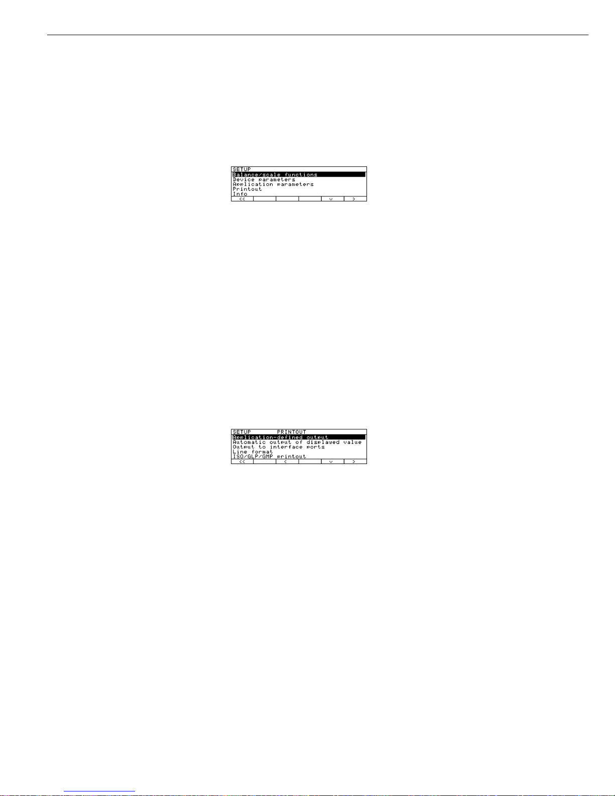
Selecting the Printout Function (PRINTOUT)
Purpose
This menu item enables you to
configure the printout to meet your
individual requirements by selecting
predefined menu parameters in the
Setup menu. Printouts of weights and
other measured or calculated values and
IDs enable you to document your data.
You can select the particular data you
wish to print. To prevent changes to
your settings, you can block access to
the menu by assigning a password.
Features
The device parameters are combined in
the following groups (1st menu level):
– Application-defined output
– Configured Printout
– FlexPrint
– Automatic output of displayed values
– Output to interface port
– Line format
– ISO/GMP printout
– Identification (identifier)
– Factory settings – printout only
Factory Settings
Parameters: The factory settings are
identified by the symbol “ο” in the list
on the next page.
Preparation
Display available printout parameters
§ Select the Setup menu: press H
> SETUP is displayed:
§ Select “Printout:” use the
q and O
soft keys
If no password has been assigned,
anyone can access the printout
parameters in the Setup menu
If a password has already been
assigned:
> The password prompt is displayed
$ If access is blocked by a password: enter
the password using the numeric and/or
alphabetic keys
$ If the last character of the password is
a letter: conclude input by pressing the
a key
§ Press
l to confirm the password
> Printout parameters are now displayed:
$ To select the next group:
press the
q soft key (down arrow)
$ To select the previous item of a group:
press the
Q soft key (up arrow)
$ To select the next sub-item within
a group: press the
O soft key
(right arrow)
$ To select the previous group:
press the
o soft key (left arrow)
$ To confirm: press the
l soft key
Extra Functions
§ Exit the Setup menu:
press the
oo soft key
> Restart your application
§ Print parameter settings:
– When the printout parameters
are displayed, press p
> Printout (Example)
SETUP
PRINTOUT
--------------------
Application defined
Stability paramete
With Stability
Print on request t
Off
Auto print upon in
All values
Configured printou
Indiv.: Printout
Comp.: Printout
Total: Printout
FlexPrint
Off
Automatic Output of
Stability paramet
Without stabili
Stop auto print
Not possible
Time-dependent aut
1 display update
Output to interface
Serial communicat:
Application-defined
output
Line format
For other apps/GLP
(22 characters)
ISO/GLP/GMP printou
Off
Identification
Lot (L ID):
ID1:
ID1
etc.
30
 Loading...