

Page 1
Operators Handbook
BAEDCU3 - Rev. 4.6 - 0504
D C U 3 - S y s t e m
Digital Measurement and Control System for Fermentors
Page 2

Page 3

Operators Handbook DCU3 – System
Introduction
BAEDCU3 - Rev. 4.6 - 0504
Introduction
Sartorius BBI Systems´ digital measurement and control system for fermentors, the DCU3 – system, is
available as stand-alone unit for operation of Sartorius BBI Systems´ laboratory scale fermentors and
as a rack version for the measurement and control cabinets of pilot plant fermentors. All information
given in the handbook refer to the operation of these fermentors, unless otherwise specified. Above
this the DCU3-system can be applied as universal measurement and control system for fermentor
automation and for customized general measurement and control tasks.
This „Operator's Handbook“ describes all standard functions available with the software version 4.6 of
the DCU3 - system. In general the range of functions implemented for a specific fermentor is smaller
than the range that this manual describes. The DCU system can be adapted to the different fermentor
types by means of the software configuration and fermentor specific features.
Besides the standard configurations the DCU3 - system can have customized configura-
tions, as required for special applications. The description of such configurations can be
added to this document or can be combined into a project-specific document.
Design, installation, start-up and use of the fermentor system are shown in the extra operating manual
of this unit. More detailed technical information on the hard- and software structure, the system installation, etc., is given in the extra „Technical Manual DCU3 - system“. If the DCU3 - system should be
used together with a host computer the corresponding protocol for communication is described in the
manual „DCU-Host Communication“. Both these manuals are available on request.
The digital control system DCU3 is one example of Sartorius BBI Systems´ product program of sophisticated fermentation and peripheral laboratory equipment. For further information about this device and
our complete product program please contact the
Sartorius BBI Systems GmbH
Schwarzenberger Weg 73-79
D - 34212 Melsungen
Tel.: +49 (0) 56 61 - 71 34 00, Fax: +49 (0) 56 61 - 71 37 02
e-mail: info@sartorius-bbi-systems.com
WebSite http://www.sartorius-bbi-systems.com
or your local representative of Sartorius BBI Systems GmbH or Sartorius AG.
Printed in Germany
© Sartorius BBI Systems GmbH. This document describes the device at the time of it s publication. Modification s
of the equiment and changes of the related documentation are preserved. No part of the documentation shall be
changed or duplicated or reprocessed for other purposes by third parties without our written permission.
Printed in Germany
Page 4

Operators Handbook DCU3 – System
Introduction
BAEDCU3 - Rev. 4.6 - 0504
Page 5

Operators Handbook DCU3 – System
Contents
BAEDCU3 - Rev. 4.6 - 0504
Contents Page
Introduction
1 Design and Function 1 - 1
2 Operating Behaviour
2.1 Switching „off“ and „on“ 2 - 1
2.2 Mains Failure 2 - 1
2.3 Shut Down Function 2 - 2
2.4 Interlocking Functions 2 - 2
3 Function Selection and Inputs
3.1 Operating Terminal 3 - 1
3.2 Inputs 3 - 7
4 Start-Menü „Main“
4.1 General Notes 4 - 1
4.2 Process Information Provided by the „Main“ Menu 4 - 1
5 Main Function „Calibration“
5.1 General Note 5 - 1
5.2 pH - Calibration 5 - 2
5.3 pO2 - Calibration 5 - 4
5.4 Redox - Calibration 5 - 5
5.5 Calibration of Turbidimetry Measurement 5 - 6
5.6 Totalizer for Pumps and Valves 5 - 8
5.7 Calibration of a Balance System 5 - 10
5.8 Flow Calibration 5 - 11
6 Main function „Control Loops“
6.1 Equipment and Functional Principles 6 - 1
6.2 Selection of Controller 6 - 2
6.3 Controller Operation in General 6 - 3
6.4 Parametrization of Controllers, in General 6 - 4
6.5 Temperature Controller 6 - 7
6.6 Stirrer Speed Controller 6 - 9
6.7 Airflow Controller 6 - 10
Page 6

Operators Handbook DCU3 – System
Contents
BAEDCU3 - Rev. 4.6 - 0504
6.8 pH - Control Function Operating as PID - Controller 6 - 11
6.9 pO2-Control Methods 6 - 12
6.10 pO2 - Cascade Controller with 3 Servo Controllers 6 - 12
6.11 pO2 - Cascade Controller with 4 Servo Controllers 6 - 16
6.12 pO2-Gasmix Controller / O2 – Enrichment 6 - 18
6.13 pO2 - Gasflow Ratio Controller 6 - 19
6.14 Oxygen (O2) – Enrichment Using 2 Massflow Controllers 6 - 22
6.15 Foam Controller 6 - 24
6.16 Dosing Pump Controller 6 - 26
6.17 Level Controller 6 - 27
6.18 Weight Controller 6 - 29
6.19 Pressure Controller 6 - 30
6.20 Gravimetric Dosing Controller 6 - 31
6.21 Setpoint Profiles 6 - 33
6.22 Timers 6 - 35
6.23 Alarm Limits of Process Values 6 - 37
6.24 Alarms of Digital Inputs 6 - 39
7 Main function „Batch Control“
7.1 General 7 - 1
7.2 Sequences 7 - 1
7.3 Process Time 7 - 5
8 Main Function „Recipes“
8.1 Overview 8 - 1
8.2 Recipe Selection 8 - 1
8.3 Controller Parameters in Recipes 8 - 3
8.4 Setpoint Profiles 8 - 4
8.5 Timers in Recipes 8 - 5
8.6 Process Value Alarms in Recipes 8 - 6
8.7 Digital Input Alarms 8 - 7
9 Main function „Maintenance“
9.1 Overview 9 - 1
9.2 Manual Operation in General 9 - 2
9.3 Manual Operation for Digital Inputs 9 - 2
9.4 Manual Operation for Digital Outputs 9 - 4
9.5 Manual Operation of Analog Inputs 9 - 6
Page 7
Operators Handbook DCU3 – System
Contents
BAEDCU3 - Rev. 4.6 - 0504
9.6 Manual Operation for Analog Outputs 9 - 8
9.7 Settings of Measurement Ranges 9 - 10
9.8 Connection of External Devices 9 - 11
9.9 Host Interface 9 - 12
9.10 Peripheral Interface 9 - 14
9.11 Balance Interface 9 - 15
9.12 System Settings 9 - 16
9.13 Service / Diagnostics 9 - 17
10 Main Function „Documentation“
10.1 Selection Menu 10 - 1
10.2 Report Printer 10 - 1
10.3 Recorder Configuration 10 - 3
11 Main Function „Password“ 11 - 1
12 Main Function „INFO“ 12 - 1
13 Alarms
13.1 Alarm Messages 13 - 1
13.2 Alarm Menu 13 - 2
14 Supplement
14.1 Alarms, Meanings and Remedial Measures (Troubleshooting) 14 - 1
14.2 Trouble Shooting for the DCU-System 14 - 5
14.3 Interlocking Functions 14 - 5
14.4 Abbreviations 14 - 6
14.5 Fermentor - Specific Adjustments of Balance Systems 14 - 8
14.6 Arrangement and Assignment Plans 14 - 9
14.7 Declaration of Conformity with EC-Directives, Standards and
Technical Specifications 14 - 9
Page 8

Operators Handbook DCU3 – System
Contents
BAEDCU3 - Rev. 4.6 - 0504
Page 9

Operators Handbook DCU3 – System
1., Design and Function
BAEDCU3 - Rev. 4.6 - 0504 1 - 1
1 DESIGN AND FUNCTION
The Digital Measurement and Control System DCU3 has been especially developed for the automation of fermentor systems. The hardware is based on an industrial 32 bit VME bus micro processor
system. All measurement and control functions are implemented in the software. The software is
stored on a PC-card, which can easily be replaced for extensions of the system by new versions.
For the fermentors of the BIOSTAT
®
series the Sartorius BBI Systems GmbH offers a broad range of
standard configurations of the DCU3 – system, which consider the features of the individual type of
fermentor. However, the extent of functions implemented for a delivered system will always depend on
the specifications of the customer, as agreed prior to ordering of the fermentor system. Therefore even
specific customized configurations are possible.
Standard functions are data acquisition, sensor calibration, alarm monitoring and control of operation
conditions. Additional software modules provide control of process conditions by changing parameters
depending on running time and state of the process. This includes setpoint profiles for controllers,
timer functions for pulsed actuators, dosing counters, etc. Complete sets of process parameters may
be predefined as recipes to allow performing of reproducible process sequences.
The DCU3 can be integrated into hierarchical automation systems via its remote interfaces. A host
computer system can be connected, such as the proven MFCS-Systems, for instance, providing functions like graphical visualization of processes, data acquisition and storage, process protocols, etc.
Page 10

Operators Handbook DCU3 – System
1., Design and Function
BAEDCU3 - Rev. 4.6 - 0504 1 - 2
Page 11

Operators Handbook DCU3 – System
2., Operating Behaviour
BAEDCU3 - Rev. 4.6 - 0504 2 - 1
2 OPERATING BEHAVIOUR
The DCU3 - system stores all parameters which are adjustable by the operator (setpoint, calibration
parameters, profiles, etc.) in a battery buffered memory. Hence these parameters are still available
when the DCU3 system is switched off and restarted again.
For enabling the outputs of the DCU3 - system and of several system functions, which directly act on
the fermentor system, 4 categories of switching-off or power failure, respectively, are differentiated:
1. Switching „off“ and „on“ using the mains switch at the front panel (see pos. 3 in fig. 1-1).
2. Shut down due to mains failure.
3. Emergency cut-off via the „SHUT-DOWN“-key at the operating terminal or using the mains
switch of the supply unit or cabinet of the fermentor (see BIOSTAT
®
MD, ED or BIOSTAT®
C-DCU3, UD, for instance).
4. Interlocking functions for system outputs.
2.1 Switching „off“ and „on“
The DCU3 - system is switched-on or off, respectively, via the mains switch on the front panel. After
being switched-on (again) the DCU3 will start at (return to) a defined state of operation:
All controllers are „off“, a ctuators are in rest position
All timers are „off“ (stopped )
No recip e loaded, no program (sterilization for example) active
2.2 Mains Failure
In the case of a (mains) power failure, after being restarted, the DCU3 - system continues its activities
as follows:
Controllers ru n on with the setpoint, which has been adjusted at the time of the power failure
Timers and setpoint profiles will be continued
Sequence s, such as sterilization programs, and recipes will be continued
The operator can set a maximum power failure time (FAILTIME) in the „maintenance“ menu. This is a
specific feature of the DCU3 - system. When the power failure lasts longer than the preset FAILTIME,
then the DCU3 - system behaves as if being switched-off with the mains switch, i.e. the system will be
shut down and set to a defined basic state.
After a power failure the system generates the message „Power Failure“, together with the time and
duration of the failure. If the maximum power failure time has expired (see „FAILTIME“), the system
displays the message „Pwf stop ferm“ with time and duration of the failure. See also the description of
the „Alarm messages“ in the supplement.
Page 12

Operators Handbook DCU3 – System
2., Operating Behaviour
BAEDCU3 - Rev. 4.6 - 0504 2 - 2
2.3 Shut Down Function
The shut down function can be released by :
Enabling the „SHUT DOWN“ key on the operating terminal and
Enabling the mains switch of the fermentor (located on the supply unit or cabine t).
In the shut down state all outputs are switched over to their predefined safe state. Other active functions of controllers, timers, profiles, recipes and sterilization are not effected.
During the SHUT DOWN state you can change any of the active functions, as required.
If the SHUT DOWN state is enabled, the DCU3 - system displays the alarm message „Shut
Down DCU“ or „SHUT DOWN FERMENTOR“
Pressing the „SHUT DOWN“ key again or restarting the fermentor supply unit with the emergency
switch terminates the shut down function. Then all outputs of the DCU are reactivated.
2.4 Interlocking Functions
Interlocking functions trigger the outputs for functions which are important for operational safe ty, i.e.:
Fixed safety functions which cannot be changed by the user.
User-definable safety functions.
An interlocking function switches certain outputs of the DCU3 over into their predefined safety state.
However, this will not effect the course of controllers, timers, profiles, recipes and of the sterilization.
For details about specific functions see section „Interlocking functions“ in the supplement.
If the cause for release of an interlocking function is no longer present, the safety state of the corresponding output will be cancelled and the output returns into its operating state.
The safety state of an output is the same as the state during SHUT DOWN.
The state of the output displayed in the menu „MAINTENANCE, MANUAL OPERATION,
DIGITAL OUTPUTS“ and „ANALOG OUTPUTS“ is „lock“.
Page 13
Operators Handbook DCU3 – System
3., Function Selection and Inputs
BAEDCU3 - Rev. 4.6 - 0504 3 - 1
3 FUNCTION SELECTION AND INPUTS
3.1 Operating Terminal
The DCU3 - system has an especially developed touch screen terminal for display of all process parameters and for operation of the entire unit. This „touch terminal“ has integrated „touch keys“ where
the operator can select the menus and the related subfunctions, enter data and select and switch-over
the modes for fermentor operation. In general the terminal is operated simply by pressing the screen
at the position of the displayed keys.
The touch terminal is adjustable to provide an optimum angle of vision:
DCU-Tower :
BIOSTAT
®
B-DCU
1. Unscrew the locating screw of the support at the rear of the
terminal a little.
2. Push the terminal backward at its upper edge or pull until
the display can be read best. Tighten the screw again.
DCU3-System in table top housing:
BIOSTAT
®
MD-DCU3, Q-DCU-
3, C/CT-DCU3
1. Push the locking device on right hand of the terminal (see
push button 4 in fig. 1-1)
2. Pull the terminal at its lower edge or push backward, until
you achieve an angle where the display can be read best.
3. Release the locking device to fix the arrangement.
Rack version of DCU3 systems :
BIOSTAT
®
D-DCU3, customized
pilot- and production fermentors
The possible way of setting the angle depend s on the
mounting of the terminal in the rack.
3.1.1 Structure of the Touch Screen Display
Page 14

Operators Handbook DCU3 – System
3., Function Selection and Inputs
BAEDCU3 - Rev. 4.6 - 0504 3 - 2
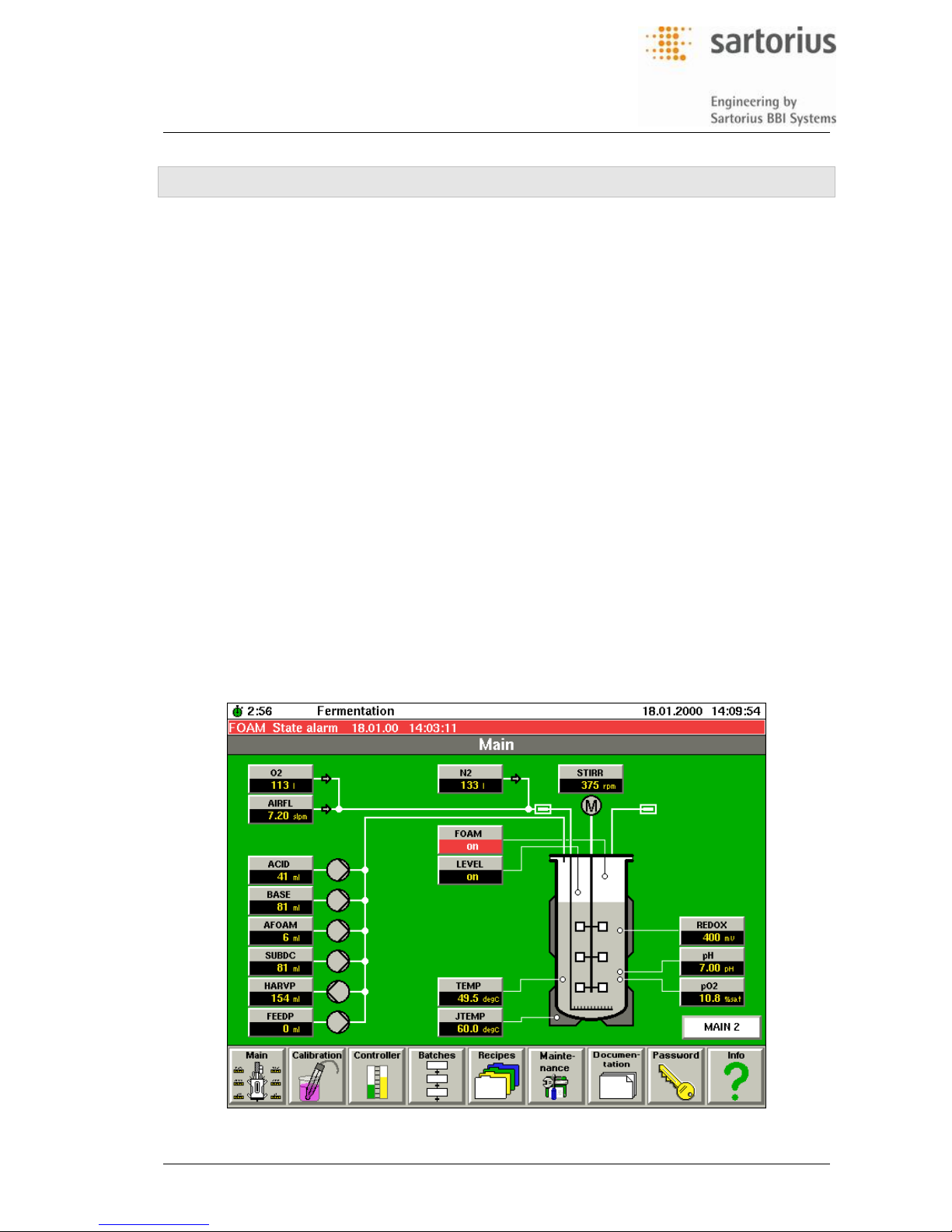
Structure of the Touch Screen Display, on the page above shown for the „Main“ menu:
1. line: Status line:
TAG Used for
hhhh:mm Display and Input of process time
Fermentation (etc.) Display of operating state. Possible displays are:
− Fermentation: System is in „Fermentation“ state
− Sequence: System runs a sequence
− Recipe 1..4: System runs a recipe (1..4)
18.01.00 14:03:11 Display of actual date and time in formate:
dd.mm.yyyy hh:mm:ss
2. line: Alarm line, display of alarms (showing the latest alarm)
3. line: name of active function in the workin g area
Workin g area: display of schematic setup of fermentor system and peripheral equipment;
– MAIN 2 : next „Main“-page
– the items displayed depend on the active function a nd can include symbols for devices,
process values, parameters, modes and settings;
– the displays of the items are designed as touch keys for direct access to submenus for
selecting functions and entering parameters.
Lowest line: Main function keys (also designed as touch-keys) for selection of submenus
and subfunctions, where parameters should be entered and operating modes should be set.
Page 15
Operators Handbook DCU3 – System
3., Function Selection and Inputs
BAEDCU3 - Rev. 4.6 - 0504 3 - 3
3.1.2 Function al Keys of the Working Area
For a selected function the lowest line of the working area can have additional touch keys, which are
especially assigned to this function and allow for direct access to the corresponding submenus.
Example: Operating display of the pO
2
- controller with touch keys:
The following touch keys for function selection are available in the working area of the oper-
ating displays:
Selection key Function
Exit Closes the actual display
PARAM Request for display of related parameters
PV - Alarm Request for display of related process value alarms
PROFILE Request for display of related setpoint profiles
CALIB Request for display of related calibration function
Available keys not shown in this example are
CLOOP Selection of the related controller menu
CLOOPx Selection of additional controller displays
MAINx Request for display of related process overviews
TIMER Request for display of related timer functions
DI ALARM Request for display of related digital input alarms
Page 16

Operators Handbook DCU3 – System
3., Function Selection and Inputs
BAEDCU3 - Rev. 4.6 - 0504 3 - 4
3.1.3 Selection of Menus and Entering of Parameters
The operation of the DCU3 - system is organized systematically. Related tasks of fermentor operation
are combined in functional groups - the „main functions“ listed below. A main function can be directly
activated at any time during the running process from any submenu by pressing the corresponding
main function touch key at the screen.
Main function Display, use
Main Graphic overview of the entire fermentor system showing the most important
process parameters and allowing for direct access to the related functions.
Calibration Calibration of sensors and pumps, taring of balance systems
Control Loops Operation of the controllers and related setpoint profiles and timers
Batch Control Operation of serial steps, batch processes, etc., such as sterilization runs
Recipes Operation of 4 recipes with preset controller parameters, setpoint profiles, tim-
ers and alarm parameters
Maintenance Manual access to inputs and outputs, measurement ranges of process values,
parameters of remote systems (such as host computers, balance systems) and
to the maintenance (service) functions
Documentation Operation of recorders and printers for documentation of the process
Info Information about the installed software / general notes
There are two possible methods to select a menu, step forward to a subfunction and enter parameters. As an example here are the possible methods for setpoint adjustment of the stirring speed:
Stepping through the menu tree as known from the former DCU1- and DCU2- systems:
1. Select the main function „Control Loops“ by pressing the touch key
2. Select the „Stirrer“ controller from the overview of controllers
3. Adjust the setpoint
Enabling the data entry function directly from the main menu. This is accomblished by object
(based) linking of the actual stirrer speed display in the main menu to the related controller
functions, i.e. „stirrer controller, setpoint profile and alarm limits“:
4. Press the „Stirrer“ - touch key in the working area of the main menu. The display directly
switches over to the menu of the stirrer controller.
5. Adjust the setpoint.
Page 17
Operators Handbook DCU3 – System
3., Function Selection and Inputs
BAEDCU3 - Rev. 4.6 - 0504 3 - 5
3.1.4 „Tou ch keys“ in the Menu „Main“
After switching on of the system the graphical overview in the menu „Main“ provides a schematic display of the main functional elements of the individual fermentor system, together with the most import
process parameters and the „touch keys“ for selection of the related functions:
Only for the single unit at fermentor systems with one culture vessel
As an overview of all subunits at fermentor systems with 2…4 culture vessels
At multible vessel fermentor systems the main menus of the subunits can be accessed as follows:
Via the touch key integrate d in the overview display showing the vessel no. of the subunit
(only for DCU3 systems available from about April 2002 on and as far as implemented).
Via the direct function key CHANGE UNIT
Menu „Main“: Direct access to the main menus of subunits at fermentors with 2..4 culture vessels:
Example: BIOSTAT
®
B-DCU twin Example: BIOSTAT® B-DCU quattro
The touch key „All vessel“ can be used to return to the overview display of all units.
The direct function key CHANGE UNIT cyclically switches over the displays of the main menus of all
units and the individual subunits:
All vessels v essel 1 vessel 2 (vessel 3, 4, if available) all vess els
Page 18
Operators Handbook DCU3 – System
3., Function Selection and Inputs
BAEDCU3 - Rev. 4.6 - 0504 3 - 6
Switching over the main menu displays for 2…4 culture vessels via
direct function key CHANGE UNIT:
CHANGE UNIT
CHANGE UNIT
.....
Page 19
Operators Handbook DCU3 – System
3., Function Selection and Inputs
BAEDCU3 - Rev. 4.6 - 0504 3 - 7
3.1.5 Direct Function Keys
The direct function keys on right hand of the „Touch Terminal“ allow for direct access to the system:
SHUT DOWN : Pressingthis key sets all analog and digital outputs into a safe state. An active
SHUT DOWN state is indicated by lighting LED in the key. Repeatedly pressing the key
cancels (releases) the SHUT DOWN state and the system returns to its previous state.
ACK : If an alarm message occurs, a red LED in the ACK - key lights. Pressing the ACK - key then
enables the alarm menu on the display.
REM : Pressing the REMote control key allows for the transmission of data from the host to the
DCU system. Effective only if a host computer is connected to the DCU-system.
CHANGE UNIT : Switching-over of the operating terminal. Applicable for DCU3-system which are
prepared for controlling several fermentors/culture vessels.
3.2 Inputs
3.2.1 Numerical and Non-numerical Inputs
Example for entering numerical inputs, shown here for the temperature setpoint:
1. Press either the touch-key „Temp“ in the working area of the „main“ menu or the key “SETP”
in the menu TEMP Control Loop
A touch key pad fades in for data input.
2. Enter the new setpoint. For this consider the
permissible setpoint range, as indicated.
3. At erroneous inputs delete the entry with CANCEL and enter the correct numbers.
4. Confirm the input with the „Ok“-key.
5. The system closes automatically the touch key
pad. The new setpoint is displayed.
Input of operating mode, i.e. controller modes:
1. Press the touch key „MODE“;
a window with the selectable modes fades in.
2. Press the touch key of the intended mode, i.e.
„off“.
3. At selection of a wrong mode, delete with CANCEL and select again the correct mode
4. The selection window closes and the display
shows the new mode.
Page 20
Operators Handbook DCU3 – System
3., Function Selection and Inputs
BAEDCU3 - Rev. 4.6 - 0504 3 - 8
Input of text:
1. Enter the text with a max. number of letters
(Range).
2. At wrong inputs delete the entry using the „<-“
key or CANCEL.
3. Confirm the Entry with „Ok“. The system closes
the keypad and displays the text.
Selection boxes (slide r): The slider can be moved as follows:
1. Pressing the arrow key
2. Moving the white zone within the slider
3. Pressing the shaded zone at the relative position of the table, which should be accessed
Special Notes
What do touch keys indicate, whose label appears in black & white dithered („light“) letters?
If a controller´s mode is set to „auto“, for instance, the data entry for the controller output is
locked. This locking of an entry against inputs is indicated on the „OUT“ key. The letters
then are displayed in black & white dithering („light“).
3.2.2 Password - System
System settings and functions, that are restricted for use by authorized personnel only, are protected
by a password. Among others these are, for instance, the setting of controller parameters (such as
PID), the setting of interface parameters and the manual operating mode.
For more detailed information refer to section “Main function “Password””.
Page 21
Operators Handbook DCU3 – System
4., Start-Menü „Main“
BAEDCU3 - Rev. 4.6 - 0504 4 - 1
4 START-MENÜ „MAIN“
4.1 General Notes
The „Main“ menu is displayed after switching on the DCU3 - system. With the new „object-based“ display of entries and the direct selection of submenus and functions for data input and mode selection,
the main menu is the control center for operation during a fermentation run.
The schematic display of the culture vessel together with the connected peripheral assemblies, the
symbols for stirrers, pumps, totalizers, balance system and the location of the electrodes facilitates the
overview over the state of the process parameters. Above this it is the starting point for easy access to
the submenus and subfunctions for inputs and selections.
4.2 Process Information Provided by the „Main“ Menu
The main menu displays the process values together with schematics of the related component parts
of the fermentor system:
Measured values for pH, pO
2
, foam, etc.;
Inputs of external actuators, such a s motor control, massflow controller;
Processed values, such as dosing volumes of pumps, totalizers, calculated values of arith-
metic functions, etc.;
Signals of external device s connected to the DCU3 - system, such as a balance system;
The extent of displayed entries, process values and parameters depends on the configuration of the
DCU3 - system for the related fermentor system. The table on next page gives an overview on commononly applied tags and entries.
Page 22
Operators Handbook DCU3 – System
4., Start-Menü „Main“
BAEDCU3 - Rev. 4.6 - 0504 4 - 2
4.2.1 Alarms
If a process value exceeds its alarm limit or if a device is switched over to an alarm state the
backround color of the corresponding symbol changes to red (in this „laser-printed“ manual
shown light-grey, see example for the entry of foam measurement).
4.2.2 Invalid Process Values
If a process value is „invalid“ the display changes to „---„, see example „flow“:
4.2.3 Direct Function Keys and Headline Text at the Touch Display
Direct Fun ction keys on the touch display have the background colour grey/white.
Headline texts (background colour white) label indicate a correlation of the functions of the
subsequent keys
Page 23
Operators Handbook DCU3 – System
5., Main Function „Calibration“
BAEDCU3 - Rev. 4.6 - 0504 5 - 1
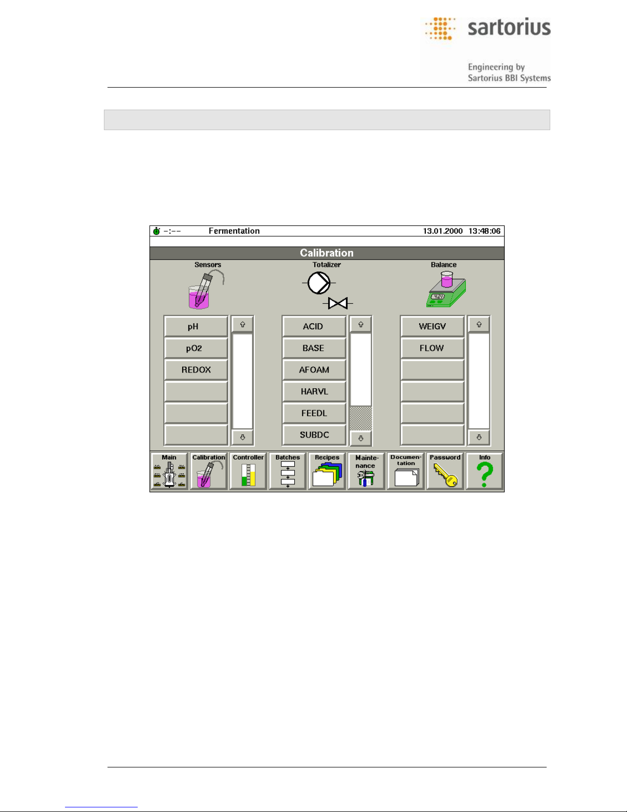
5 MAIN FUNCTION „CALIBRATION“
5.1 General Note
All calibration functions required for routine operation of the fermentor can be executed using the main
function „calibration“. You can select the following functions via the corresponding selection menu:
Selection menu „Calibration“:
The entries refer to the following functions:
– „Sensors“ : calibration of the electrodes using calibration buffers and standard conditions
– „Totalizer“ : calculation of the delivery of the addition agent pumps for dosing counters
– „Balance“ : the functions required for (pre)setting of balan ce systems, such as zero taring
and tare correction
You will enter all inputs at the touch terminal. Context based information displayed on the
terminal will guide you through the individual menus, telling you which inputs and selections
are required. The DCU3 - system automatically adapts the related (measured or calculated)
process values to the settings resulting from the calibration.
The calibration parameters will be stored when the DCU3 - system is switched off. Hence
the DCU3 - system will use these settings again for the calculation of parameters, when it is
restarted for continueing a process or for a new process, until the calibration is done again.
Page 24
Operators Handbook DCU3 – System
5., Main Function „Calibration“
BAEDCU3 - Rev. 4.6 - 0504 5 - 2
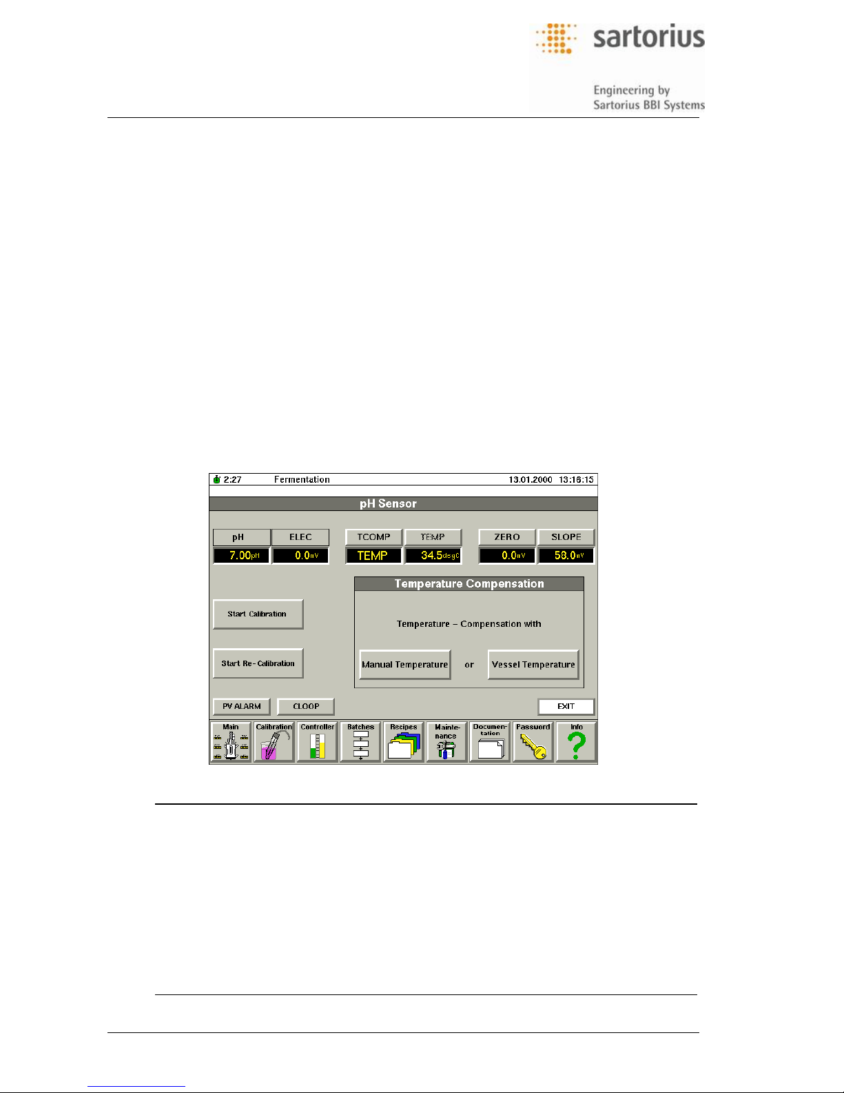
5.2 pH - Calibration
The pH electrode is calibrated by a two-point calibration using liquid buffers. The calibration is done
before the electrode is installed in the culture vessel. For details about preparing of the pH-electrode
and handling during calibration see the operating information delivered by the manufacturer. For details about mounting the electrode into the culture vessel, see the fermentor´s operating manual.
The calibration determines the „zero drift“ and „slope“ of the electrode. The measured pH-value is calculated from the electrode voltage using the Nernst equation, considering the „zero drift“, „slope“ and
„temperature“. During calibration the temperature is entered manually. For pH-measurement during
the process temperature effects are compensated via the measured temperature in the fermentor.
The impact of heat during the sterilization can cause a zero drift of the electrode. To compensate for
such effects the DCU3 - system allows to recalibrate the pH-electrode during the process. You can
measure the pH-value in a sample taken from the fermentor and enter this value into a corresponding
menu. The software recalculates the zero drift and displays the corrected „in-situ“ pH-value afterwards.
The operating display for the pH - electrode shows the pH value, the electrode voltage and the electrode parameters „zero drift“ and „slope“. Thus the functioning of the electrode can be easily checked.
5.2.1 Operating Display
Tag Entry Displayed value or function, required input
pH pH Display of measured pH value,
input of pH-value measured in sample for recalibration
ELEC mV Display of measured electrode voltage (raw signal)
TCOMP Display “temperature compensation”
TEMP Display of temperature for temperature compensation
ZERO mV Display of zero drift
SLOPE mV/pH Display of slope
Start Calibration Enabling the calibration function
Start Recalibration Enabling the recalibration function (during the process)
Page 25

Operators Handbook DCU3 – System
5., Main Function „Calibration“
BAEDCU3 - Rev. 4.6 - 0504 5 - 3
Additional touch keys, tags and entries displayed depending on the selected function:
Tag Entry Displayed value or function, required input
TMPCO degC Input of temperature for manual temperature compensation
BUFFZ pH Input of pH-value of zero buffer
− note pH-value on the buffer bottle for the actual temperature
BUFFS pH Input of pH-value of slope buffer
− note pH-value on the buffer bottle for the actual temperature
5.2.2 Calibration
The pH - electrode is calibrated before installation into the culture vessel, e.g. prior to the sterilization.
Tip: Since the heat impact during the sterilization and chemical compounds of the culture me-
dium may effect the measurement characteristics of the electrode, it must be calibrated and
checked for proper function regularly (i.e. prior to any new fermentation run).
1. Start the calibration routine by pressing the „Start Calibration“ touch key.
2. Follow the instructions given in the related submenus.
5.2.3 Recalibration
Via these steps you can adapt the pH-measurement function to changing measuring char-
acteristics of the electrode, as it may be caused by heat impact during the sterilization or by
chemical reactions of the electrolyte with the culture medium, for instance:
1. Measure the actual pH-value in a sample taken from the running fermentation, using conventional pH-measuring techniques.
2. Start the calibration by pressing the „Start Recalibration“ touch key.
3. Follow the instructions given in the related submenus.
The DCU-system automatically recalculates the zero drift caused by the sterilization and
displays the corrected pH-value.
5.2.4 Special Notes
If necessary the values for „zero drift“ and „slope“ can also be entered directly in the corre-
sponding sections of the display.
The electrode has a restricted maximum lifetime which depends on the operating conditions
and the application. The electrode should be serviced or replaced, whenever the functional
check and the calibration indicate a malfunctioning.
The pH - electrode must be serviced or replaced if :
– the zero drift is beyond the range of -30 ...+30 mV
– the slope is beyond the range of 56...59 mV/pH
You'll find specific information about recommended service periods and estimated lifetime of
the electrode in the manufacturer´s documentation included in the delivery of the electrode.
Depending on the type of fermentor and the delivered pH-electrode, the operation and main-
tenance measures required for the electrode may differ from the information herein. You'll
find more detailed information about proper handling of the electrode during calibration and
installation into the culture vessel in the Operating Manual of the fermentor.
Page 26

Operators Handbook DCU3 – System
5., Main Function „Calibration“
BAEDCU3 - Rev. 4.6 - 0504 5 - 4
5.3 pO2 - Calibration
The pO2 - electrode is calibrated in terms of percentage oxygen saturation, „% pO2“. The calibration is
a two-position calibration. In a fermentor the oxygen-free culture medium is the zero reference and the
medium saturated with oxygen is the „100 % pO
2
“ - reference. The pO2-electrode is calibrated while it
is installed in the culture vessel and after the sterilization. Therefore the calibration considers possible
interferences resulting from heat impact or chemical effects during sterilization.
In in-situ sterilized culture vessels you can enter the current of the electrode measured at
the end of the sterilization cycle as zero reference of the electrode.
If it is impossible to measure the zero current before air is introduced, you can connect a ni-
trogen source to the air input and gas the vessel with oxygen-free nitrogen to replace the
oxygen dissolved in the medium.
The slope can be measured after gassing the medium with air (or gas mixtures containing
oxygen) at the operating conditions intended for the process. During the process the DCU system calculates the actual pO
2
considering the zero reference, slope and temperature.
The structure of the operating display for calibration of the pO
2
-electrode is nearly the same as for the
pH-calibration. See the display on your DCU - system for details or refer to the pH - calibration display.
The display shows the „pO
2
-saturation“ (% pO2), the actually measured electrode current, the actual
temperature and the zero and slope current together with the calibration conditions. This, in addition,
allows a simple function control of the pO
2
-electrode.
5.3.1 Calibration
5.3.1.1 Zero Calibration
1. Before starting the zero calibration: sterilize the vessel (i.e. run the sterilization cycle at insitu sterilizable fermentors) or
– connect a supply of oxygen-free nitrogen and ga s the medium until any dissolved oxygen
is exhausted.
2. Inititate the calibration of the electrode´s zero via „Start ZERO Calibration“. Follow the instructions given in the calibration menu.
If the displayed zero current (ZERO: ....) is not in the range of 0 ... +10 nA, the pO
2
-
electrode must be checked and serviced.
5.3.1.2 Calibration of Slope
1. Gas the medium with air (or the intended gas mixture containing oxygen) at the conditions
(flow rate, pressure, temperature) intended for optimum oxygen supply. A constant electrode current will indicate that the medium is saturated with oxygen.
2. Inititate the slope calibration via „Start SLOPE Calibration“ and follow the instructions given
in the calibration menu.
If the measured current re mains below 30 nA, the electrode must be checked and serviced.
5.3.2 Special Notes
At a first use or at any time the pO
2
-electrode has been disconnected from the amplifier for
more than 5 ... 10 min. it must be polarized. This polarization takes at least 6 h (the time will
be shorter, if the electrode is disconnected for only a few minutes). See information in the
Operating Manual of the fermentor or in the documentation delivered with the electrode.
If necessary the „Ze ro“ and „Slope“ can be entered manually into the corresponding fields.
Page 27
Operators Handbook DCU3 – System
5., Main Function „Calibration“
BAEDCU3 - Rev. 4.6 - 0504 5 - 5
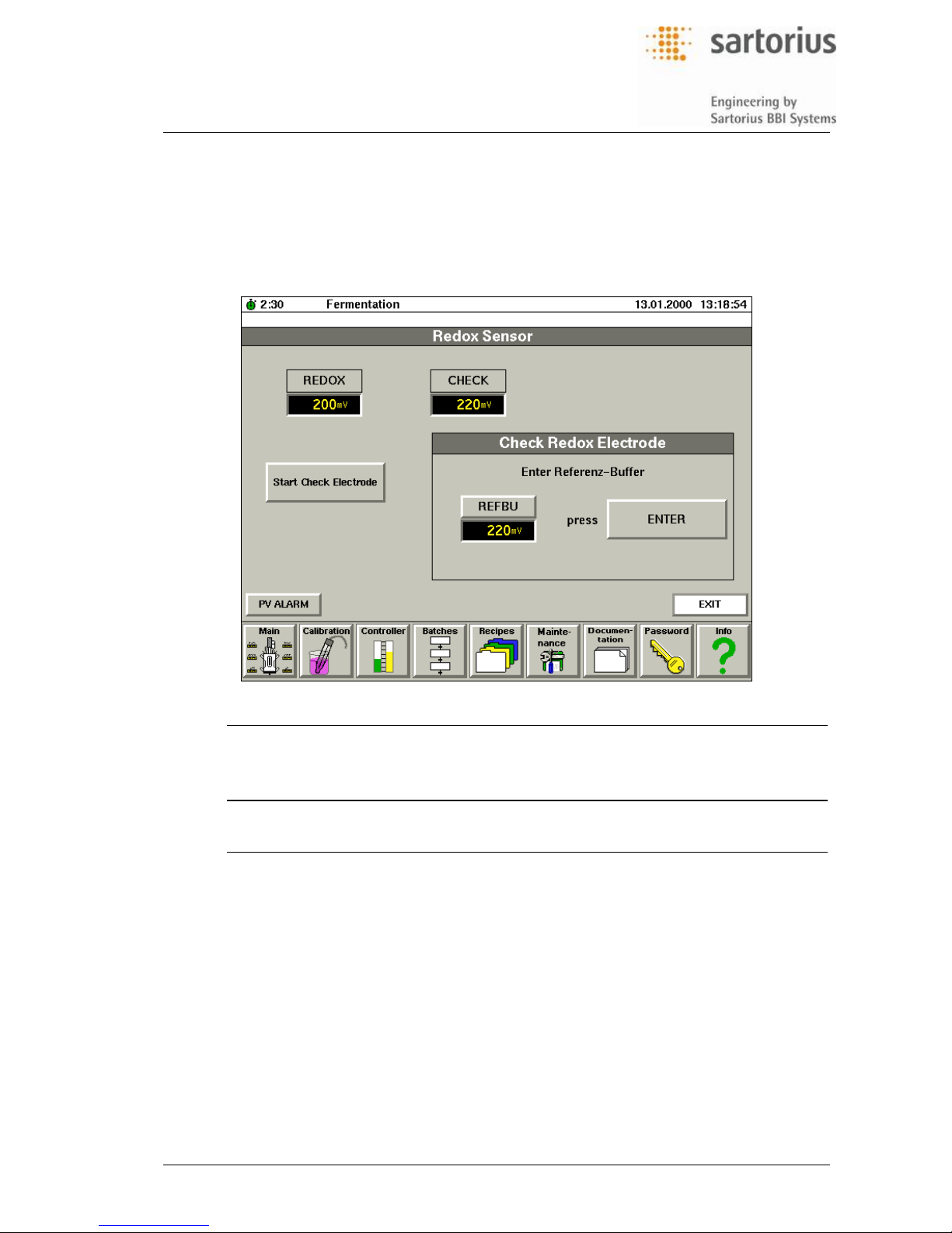
5.4 Redox - Calibration
The Redox calibration is in fact a functional check. You will measure a calibration buffer and compare
the measured value with the reference indicated on the buffer bottle. If these values are different, the
Redox can be entered manually. The DCU - system then calculates a corresponding correction factor.
5.4.1 Operating Display
Tag Entry Displayed value or function, required input
REDOX mV Display of combined electrode voltage
CHECK mV Display of combined electrode voltage of last calibration
Start Check Electrode Enabling calibration of the Redox electrode
Additional touch keys, values and functions available in this display:
REFBU mV Enter reference voltage of redox buffer
5.4.2 Functional Check
The electrode function is checked before it is mounted into the culture vessel and therefore prior to the
sterilization. Since the heat impact of sterilization or chemical reactions with compounds of the culture
medium may effect the measuring characteristics of the electrode its function should be checked regularly, i.e. prior to any next use and, if wrong operation is suspected, after a fermentation run.
1. Place Redox electrode in a beaker filled with the reference buffer
2. Enable functional check via „Start check electrode“. Follow the instructions of the menu.
5.4.3 Special Notes
If the measured buffer Redox and the value on the buffer bottle deviate by more than 6 mV
(about 3%) the electrode must be serviced. See documentation delivered with the electrode.
Page 28
Operators Handbook DCU3 – System
5., Main Function „Calibration“
BAEDCU3 - Rev. 4.6 - 0504 5 - 6
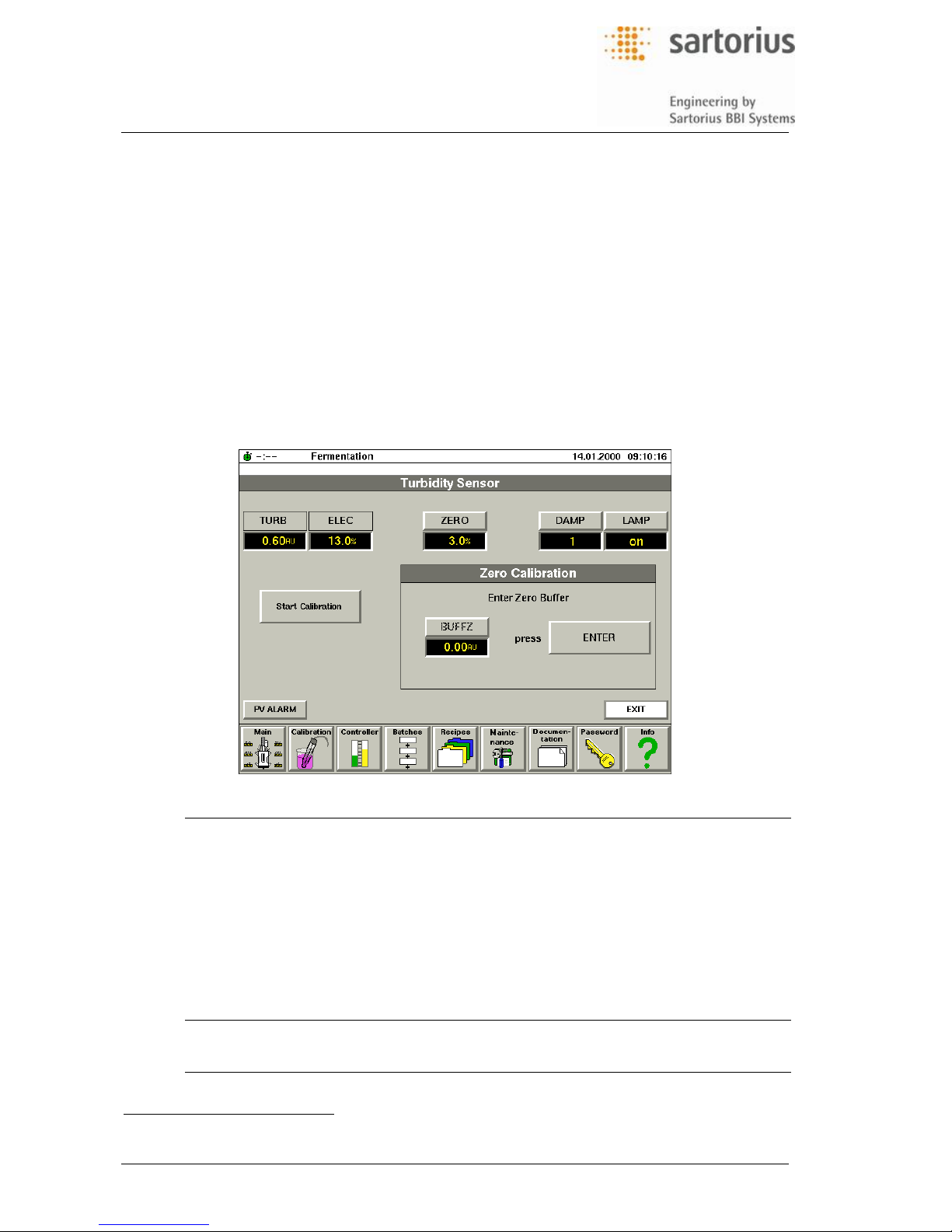
5.5 Calibration of Turbidimetry Measurement
Calibration of the turbimetry measurement probe is a „single-step“ procedure evalulating the „zero deviation“ of the sensor is. For this the sensor is placed into particle- and bubble-free deinonized water.
The system calculates the turbidimetry as the arithmetical mean of the value measured during a defined measuring time in terms of „absorption units, AU“. For calculation the system considers the zero
deviation and a selectable damping factor „DAMP”. To obtain stable turbidimetry measurements, the
damping factor „DAMP“ can be selected in 4 stages.
The operating display of the turbidimetry sensor includes the data field for absorption units (AU), the
percentage sensor raw signal [%] and the zero deviation against „0 AU“. This allows for an easy functional check of the sensor. The lamp contained in the turbidimetry sensor can be switched on and off
via the „Sensor Calibration“ - menu, see LAMP-entry
1)
.
5.5.1 Operating Display
Tag Entry Displayed value or function, required input
TURB AU Display of process value in 0...6 AU (Absorbing Units)
ELEC % Display of percentage raw signal of the sensor
ZERO % Display of zero deviation after calibration
LAMP
1)
On/off Display and selection of switching state of lamp in the sensor
DAMP 1 ... 4 Display and input of signal damping. The input signal is proc-
essed as the mean value of a floating reference window.
Damping factors base upon 4 selectable reference windows:
- step 1 = 6 s; step 2 = 12 s; step 3 = 30 s; step 4 = 60 s
Start Calibration Enabling the calibration routine
Additional touch keys, values and functions available in this display:
BUFFZ AU Display of zero solution
1)
Only Fundalux I – system, not applied with Fundalux II (available as option from 2004 on)
Page 29

Operators Handbook DCU3 – System
5., Main Function „Calibration“
BAEDCU3 - Rev. 4.6 - 0504 5 - 7
5.5.2 Calibration
For calibration of the turbidimetry sensor proceed as follows.
1. Start the calibration via „Start Calibration“
2. Follow the instructions of the calibration menu.
5.5.3 Special Notes
1. If the lamp
1)
is switched on, it will be kept in „on“-state when the DCU3 - system is switched
off and on again.
2. If required, the percentage zero deviation can directly be entered in the ZERO-entry.
Page 30
Operators Handbook DCU3 – System
5., Main Function „Calibration“
BAEDCU3 - Rev. 4.6 - 0504 5 - 8
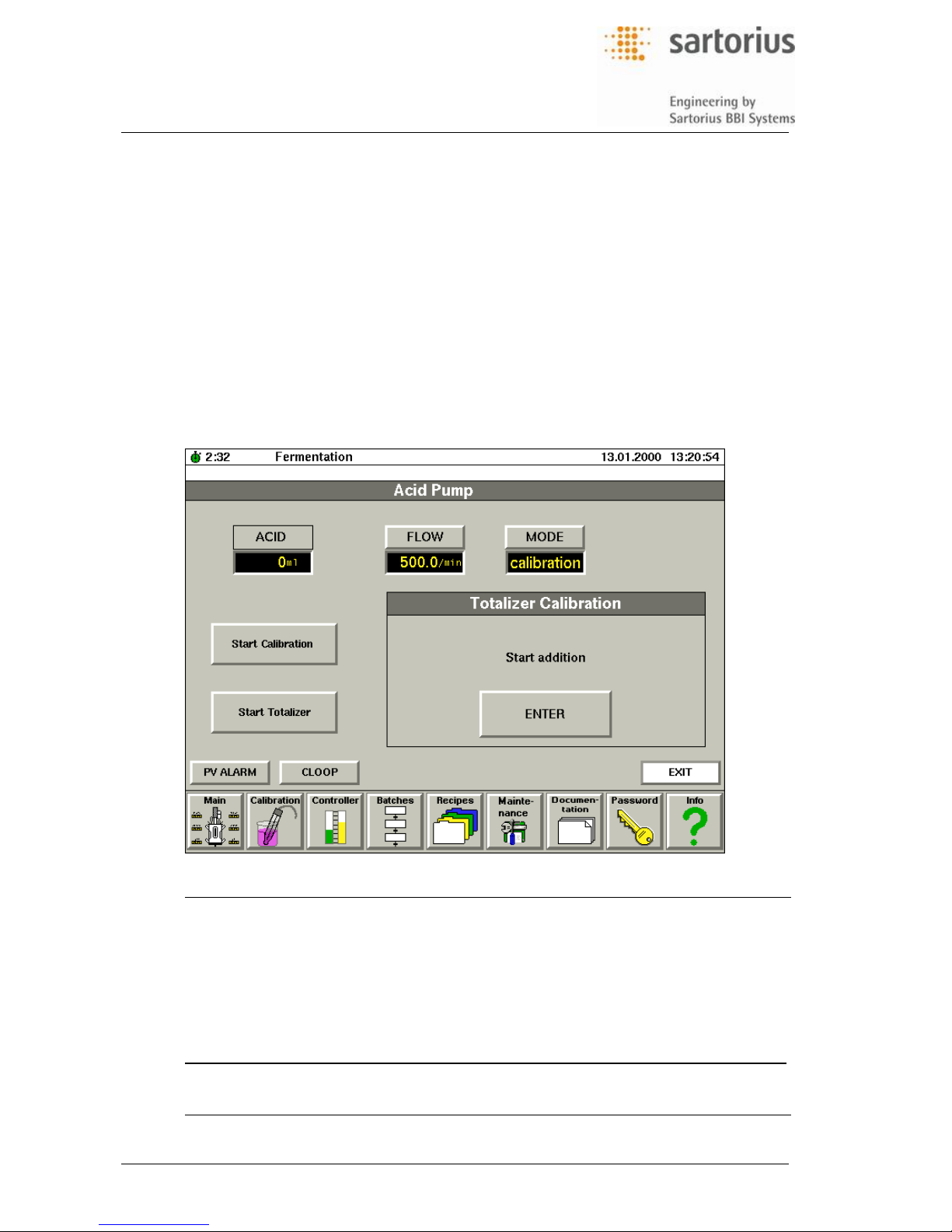
5.6 Totalizer for Pumps and Valves
For monitoring of the corrective agent consumption the dosing times of the pumps or of the dosing
valves are totalized and used as process values. The DCU3 - system converts the dosing times into
delivered volumes considering the specific flowrates of the pumps or of the dosing valves.
The dosing counters can be zeroed at any time via the operating display. If the specific flowrates are
known, you can enter them directly via the touch display. If the flowrates must be evaluated you can
use the „Calibration Totalizer“ function. Furthermore the flowrates can be calculated automatically during the calibration process from the measured running time and the entered delivery volume.
The standard configurations of the DCU-system include calibration routines and dosing counters for
acid, base, antifoam, feed, harvest and substrate. Since the calibration and dosing counter functions
are the same for all pumps and dosing valves, only those for the acid pumps will be described herein.
5.6.1 Operating Display
Tag Entry Displayed value or function, required input
ACID ml Display of delivered volume of liquid
FLOW ml/min Display of calculated delivery or input of either specific
pump delivery or valve flow, as far as known
Start Calibration Enabling the calibration
Reset Totalizer Resetting the dosing counter to zero
PV ALARM Enabling the alarm display
CLOOP Selection of the controller menu
Additional touch keys, values and functions available in this display::
VOLUME ml Input of volume delivered during calibration
Page 31

Operators Handbook DCU3 – System
5., Main Function „Calibration“
BAEDCU3 - Rev. 4.6 - 0504 5 - 9
5.6.2 Calibration of a Pump
For calibration allways use tubings of the same type and dimensions as for the delivery of
media during the process.
1. Place one end of the tubing into a beaker filled with water and the other end into a measuring beaker. Complete fill the tubing with water. For this you can manually activate the pump.
2. Start the calibration of the pump via „Start Calibration“.
3. Follow the instructions shown at in the DCU3 - display.
The DCU - system automatically calculates the flowrate considering the internally recorded
running time and measured delivery and displays the result in the entry „FLOW : x /min“).
5.6.3 Activation of the Dosing Counter
The dosing counter will automatically be started when the calibration of the pump is finished
and the corresponding controller is activated.
5.6.4 Special Notes
If already known, the delivery rate of the pump or of the dosing valve can be directly entered
into the FLOW - entry.
Page 32

Operators Handbook DCU3 – System
5., Main Function „Calibration“
BAEDCU3 - Rev. 4.6 - 0504 5 - 10
5.7 Calibration of a Balance System
The fermentor weight (the „vessel content“) can be measured by balance platforms or load cells (i.e.
optional accessories). They will be connected to the DCU3 via a strain gauge measuring amplifier.
The measurement amplifier is scaled to a gross weight output signal. The gross weight comprises the
empty vessel with the drive system, the individual vessel equipment and the vessel content (medium).
„Zero-taring“ using the calibration function is done by measuring the weight of the completely
equipped culture vessel without the culture medium and setting this weight as the „net weight“. However, tare correction is possible after changing the equipment of the culture vessel during a running
process. For this the net weight is stored and the tare weight will be adapted to the changing gross
weight.
5.7.1 Operating Display
Tag Entry Displayed value or function, required input
WEIGV kg display of net weight (WEIGH = GROSS - TARE)
GROSS kg display of gross weight
TARE kg display of tare weight
Start Taring Enabling the taring function
Start Hold Enabling the „hold“ function
PV ALARM Enabling the alarm display
CLOOP Selection of the controller menu
5.7.2 Calibration
1. For zero taring with the culture vessel being fully equipped, but without culture medium, start
the calibration with „Start taring“. Follow the instruction shown in the calibration menu.
2. If the culture vessel equipment is changed during the process, you can recalibrate the taring. Start the „Hold“ function for this and follow the instructions in the menü.
Page 33

Operators Handbook DCU3 – System
5., Main Function „Calibration“
BAEDCU3 - Rev. 4.6 - 0504 5 - 11
5.8 Flow Calibration
The dosing control function of the DCU3 - system operates with a remote balance system, which
measures the weight of the substrate. The balance system is connected to the DCU3 - system via a
serial interface. By default the actually measured weight will be transmitted to the DCU3 every five
seconds. The menu has an optional manual refilling function. This allows the use of low cost balance
systems which offer only small weight ranges.
Connecting a balance system via the serial interface also allows for measuring external weights. At an
existing FLOW-CALIBRATION menu one remote balance with serial interface can be connected to the
DCU3 without hardware extensions. One extension allows for up to 12 measurements.
The system calculates the volume delivered per time, the „massflow“, considering the actual weight
measured with the balance and the spent time. To minimize disturbances the calculation is based
upon a „dynamic calculation“ of the mean value. All values measured within a passed interval of either
1 min, 10 min or 60 min will be considered. The user can select this interval according to the process.
5.8.1 Operating Display
Tag Entry Displayed value or function, required input
FLOW kg/h Display of actual flow
WEIGF kg Display of net weight
Refill Enabling the refill function
Reset Flow Reset of the displayed flow (enable start with „0.00“)
CYCLE Input of calculation interval (cycle)
1
− interval of 1 minute
10
− interval of 10 minutes (recommend setting)
60
− interval of 60 minutes
PV ALARM Enabling the alarm display
CLOOP Selection of the controller menu
Page 34

Operators Handbook DCU3 – System
5., Main Function „Calibration“
BAEDCU3 - Rev. 4.6 - 0504 5 - 12
5.8.2 Special Notes
1. It is recommende to set a cycle interval of 10 minutes.
2. When selecting an interval of 10 or 60 minutes, respectively, the calculation and display of
the flowrate starts with the shortest interval and automatically switches over to the next
longer one. The flowrate of the initial phase is calculated from the shortest interval. This is
also true when a new setpoint is defined for the dosing controller.
The same is true for presetting a new setpoint of the dosing controller.
3. For manual refilling switch over to „Refill“-mode.
The automatic calculation of the actual flow will be stopped. The dosing controller continues
to act upon the last flow calculated. You can now refill the substrate storage vessel (bottle)
and tare the balance again. After switching over to „contr.“ mode the system starts with recalculation of the flow and continues dosing, now considering the actual values.
Page 35

Operators Handbook DCU3 – System
6., Main function „Control Loops“
BAEDCU3 - Rev. 4.6 - 0504 6 - 1
6 MAIN FUNCTION „CONTROL LOOPS“
6.1 Equipment and Functional Principles
All control loops in the DCU3 - system are DDC controllers. They operate either as PID controllers,
setpoint controllers or on/off controllers and are adapted to the related control loops. Depending on the
actuator their output is either continuous or pulsewidth-modulated (pwm). Both single- and split-range
controls are possible. The controller structure (PID) can be parametrized, if necessary. Switching over
between the operating modes is carried out with bumpless transfer.
These modes can be selected:
Mode State of controller
off controller switched off with defined output
auto controller in operation
manual manual control of controller / actuator
profile time profile for setpoint
cascade servo controller in cascade control loop
In the controller display you can enter actual values, operating modes and controller outputs. Effective
ranges depend on the configuration implemented for a specific fermentor. The parametrization display
for adjustment of PID parameters, output limits and deadband is accessible via a password. In remote
operation setpoint and operating mode are specified by the host computer.
The extent of implemented controllers depend on the fermentor system and/or the individual
customized configuration. The controllers shown below can be implemented at present.
Temperature controller PID cascade controller, pwm-splitrange outputs for heating /
cooling
Stirrer controller Setpoint controller for external motor control
pH controller PID controller with pwm-split-range outputs for acid/base
pO
2
controller PID cascade controller for speed, airflow or pressure servo
controller (switchable)
pO
2
gasflow ratio controller Master controller for gasflow ratio controller
Gasflow ratio controller Ratio controller of two external massflow controllers
pO
2
Gasmix controller PID controller, with pwm continuous outputs for control of
N
2/O2
Airflow controller Setpoint controller for external massflow controller
Foam controller On/off controller for antifoam
Level controller On/off controller external harvest and/or feed pump
Feedpump controller Setpoint controller for external dosing pump
Pressure controller PID controller, continuous output pressure control valve
Weight controller PID controller, pwm-output for external harvest pump
Dosing controller PID controller for control of a external dosing pump
Note: Additional or alternate controller functions can be implemented into existing DCU-systems
lateron by changing the configuration, for instance. Above this, the software allows implementing of special control functions, if necessary.
Page 36

Operators Handbook DCU3 – System
6., Main function „Control Loops“
BAEDCU3 - Rev. 4.6 - 0504 6 - 2
6.2 Selection of Controller
6.2.1 Operating Display
Tag Entry Displayed value or function, required input
PV [PV] Display of actual process value, entry (= physical unit) depending on
process value
SETP [PV] input of setpoint, entry (= physical unit) depending on process value
MODE
input of controller mode
off
− master controller and servo controller switched off
auto
− master controller switched on, servo controller switched to „cascade“
manual
− manual access to controller output
prof
− timer profile for setpoint
TEMP, etc. selection of controller display
TIMER selection of timer for digital output
CLOOP selection of the controller menu
Page 37

Operators Handbook DCU3 – System
6., Main function „Control Loops“
BAEDCU3 - Rev. 4.6 - 0504 6 - 3
6.3 Controller Operation in General
In general the operation of the DDC-controller is almost the same. Operation in cludes the necessary
changes of the setpoints, of the controller modes and of the controller outputs. Additional controller
settings not required for routine operation, will be done via the parametrization functions.
6.3.1 Operating Display (Example for Temperature Controller)
Tag Entry Displayed value or function, required input
TEMP, etc [PV] Display of physical unit of actual value, such as „degC“ for TEMP,
„rpm“ for STIRR, „pH“ for pH-value, „% sat“ for O
2
saturation, etc.
SETP [PV] Input of setpoint in the physical unit of the process value, such as
„degC“ for TEMP, „rpm“ for STIRR, „pH“ for pH-value, etc.
MODE Input of controller mo de
off
− master controller and servo controller switched off
auto
− master controller on, servo controller switched to „cascade“ mode;
cascade
− servo controller operating in cascade mode (only some controlle rs)
profile
− timer profile for setpoint running (only some controllers)
manual
− manual access to controller output;
OUT % Display of controller output in [%]; inputs possible in mode „manual
PARAM Input of password for access to controller parameter
PV ALARM Enabling the alarm display
PROFILE request for setpoint profile
CALIB request for calibration function (only some controllers)
Page 38

Operators Handbook DCU3 – System
6., Main function „Control Loops“
BAEDCU3 - Rev. 4.6 - 0504 6 - 4
6.4 Parametrization of Controllers, in General
For optimum adaptation of the DDC controllers to the control loops of the fermentor, the operator can
change important control parameters of individual controllers via the parametrization displays:
MIN, MAX : Minimum and maximum limits for the controller output
DEADB : Deadband adjustment (only for PID controllers)
XP, TI, TD : PID-Parameter (only PID controllers)
The parametrization display combined with a controller display is only accessible by entering a password. On delivery a DCU3 - system is configured with such control parameters that ensure a stable
control of the fermentor system it is designed for. For details about the parameters preset in the factory see the corresponding table in the supplement or in the documentation delivered extra for customized configurations of the DCU3 – system.
Changing the preset control parameters is not necessary under normal use. An exception are control
loops which vary with the fermentation process, such as for pH- and pO
2
-control.
6.4.1 Output Limits
For setpoint controllers and PID controllers the controller outputs can be limited (MIN and MAX). Thus
unintended high actuator changes can be avoided and, for cascade controllers, the setpoint for the
servo controller can be limited.
The limits must be entered at MIN for the „minimum output“ and MAX for the „maximum
output“. All settings are in terms of [%].
For full contro ller output range the following limits must be entered:
– single controller output : MIN = 0%, MAX = 100 %
– splitrange controller output : MIN = -100 %, MAX = 100 %
6.4.2 Deadband
For PID controllers a deadband can be adjusted. If the control deviation is within this deadband the
controller output remains constant or is set to zero (specific feature of the pH controller). By means of
the deadband a more stable control with minimized actuator changes can be achieved for actual values which vary stochastically. Furthermore, this will avoid oscillating of the controller output for splitrange controller outputs (e.g. continuously alternating acid-alkali dosag e by the pH - controller).
The deadband is adjusted in the entry DEADB as percentage [%] of the measurement span
of the corresponding actual value. It is symmetrical to the adjusted setpoint.
example for pH controller: - measurement range pH = 2 - 12 pH
- measurement span 10 pH
- adjusted deadband ± 0.1 pH
- adjusted setpoint 6.0 pH
Then the pH-control is inac tive at an actual value of 5.9 pH - 6.1 pH
Page 39

Operators Handbook DCU3 – System
6., Main function „Control Loops“
BAEDCU3 - Rev. 4.6 - 0504 6 - 5
6.4.3 Operating Display
Tag Entry Displayed value or function, required input
MIN % Input of minimum output limit, representing the setpoint minimum for
the servo controller (0 ... 100 % = measuring range of process value)
MAX % Input of minimum output limit, representing the setpoint minimum for
the servo controller (0 ... 100 % = measuring range of process value)
DEADB [PV] Input of deadband; physical unit depending on process value
XP % Input of proportional range in [%] of the measuring range
(100 % = maximum measuring range of process value)
TI sec Input of reset time
TD sec Input of rate (delay) time
Process
Value
Selection of intended process value for control if double measurements
are applied
Page 40

Operators Handbook DCU3 – System
6., Main function „Control Loops“
BAEDCU3 - Rev. 4.6 - 0504 6 - 6
6.4.4 PID-Parameter
The PID - controllers can be optimized via the PID - parameters Xp, TI and TD in the corresponding
entries of the menu. The implemented digital controllers allow changes of the control behavior (P, PI,
PD, PID) and of the parameters during operation, which simplifies the optimization of the controllers.
Xp: Proportional ran ge in [%] of measurement range (P-section)
TI: Reset time in seconds (I-section)
TD: Rate time in seconds (D-section)
The control structure can be adjusted by setting the individual PID - parameters to zero :
– P-controller -> TI = 0, TD = 0
– PI-controller -> TD = 0
– PD-controller -> TI = 0
– PID-controller -> alle PID-Parameter defined.
6.4.5 PID Controller Optimization
An optimum adaptation of a PID - controller to its control loop requires detailed knowledge in control
theory. You may refer to any standard literature for proven adjustment rules (e.g. Ziegler Nichols).
Thus the following details are only general guidlines:
The D section (TD) should only be activated in the case of quite stable actual values. Oth-
erwise, if the actual values are varying stochastically the controller output will change considerably and fast. This will lead to an unstable control behavior.
As a general rule the TI : TD ratio should be 4 : 1.
In the case of a periodic oscillating control loop the following measures are recommended:
– increase Xp
– increase TI/TD
If the readjustm ent is too slow after setpoint jumps or if the actual value drifts, the following
measures are recommended:
– decrease Xp
– decrease TI/TD
Page 41

Operators Handbook DCU3 – System
6., Main function „Control Loops“
BAEDCU3 - Rev. 4.6 - 0504 6 - 7
6.5 Temperature Controller
The temperature is controlled via a cascade control with a master controller for the vessel temperature
and a servo controller for the jacket temperature. The output of the servo controller controls the steam
valve (or an electric heater) and the cooling valve in split-range operation via pulsewidth-modulated or
continuous outputs.
The master controller can be switched from PD-behavior at start-up to PID when approaching the setpoint, which minimizes overshooting. When the temperature controller is switched off, an additional
digital output switches off the circulation pump and the heating contactor in the fermentor.
The temperature control is operated via the displays for the master controller [TEMP] and the servo
controller [JTEMP]. However, since all operations for the servo controller are activated automatically,
the adjustment of setpoints and operating modes need only be carried out at the master controller.
6.5.1 Operating Display for Master Controller (Vessel Temperature)
For a description of the tags, the physical units or entries, the displayed value or function
and of the required inputs see the table in section 6.3, Controller Operation in General.
Page 42

Operators Handbook DCU3 – System
6., Main function „Control Loops“
BAEDCU3 - Rev. 4.6 - 0504 6 - 8
6.5.2 Operating Display for Servo Controller (Jacket Temperature)
For a description of the tags, the physical units or entries, the displayed value or function
and of the required inputs see the table in section 6.3, Controller Operation in General.
6.5.3 Operation
For routine adjustment of setpoint and operating mode only the master controller [TEMP]
must be operated. Direct manual adjustment of the heating and cooling system is possible
at the servo controller [JTEMP], when it is switched over into „manual“ mode.
For test purposes it is possible to split the cascade control and specify a setpoint for the
jacket temperature in „auto“ mode via the servo controller [JTEMP].
6.5.4 Special Notes
When the master controller is in „auto“ or „profile“ mode, the servo controller is automatically
switched over into „cascade“ mode. When the master controller is in „off“ mode, the servo
controller is also automatically switched to „off“ mode.
The servo controller cannot be operated with time profiles. A setpoint limit for the servo con-
troller can be parametrized via the MAX output limit of the master controller, for instance:
– BIOSTAT
®
MD: MAX = 63,3 [%] (corresponding to 95 °C, for prevention of excessive
jacket temperature during the process)
– BIOSTAT
®
ED and UD: MAX = 98,3 [%] (corresponding to 147 °C; for prevention of
overheating during sterilization)
For the default output limits of your fermentor system, see the configuration documentation
delivered extra. As a general guideline, the output limits for autoclaveable fermentors may
be preset like the BIOSTAT
®
MD, the limits for insitu-sterilizable fermentors may be preset
like the BIOSTAT
®
ED.
Page 43

Operators Handbook DCU3 – System
6., Main function „Control Loops“
BAEDCU3 - Rev. 4.6 - 0504 6 - 9
6.6 Stirrer Speed Controller
The speed of the stirrer motor is controlled via an external, extra motor controller. You will adjust all
stirrer speed parameters at the DCU3 system. The control function of the DCU3 system works as a
setpoint controller and supplies the analog setpoint signal to the motor controller. Furthermore the
menu displays the stirrer speed signal delivered from the motor controller.
When the stirrer speed controller is switched to „off“, an additional digital output switches off the motor
contactor. If the fermentor is equipped with a pO
2
- controller the stirrer speed controller can be
switched as a servo controller in the pO
2
cascade control loop.
6.6.1 Operating Display
For a description of the tags, the physical units or entries, the displayed value or function
and of the required inputs see the table in section 6.3, Controller Operation in General.
6.6.2 Special Notes
In „manual“ mode, when entering the MIN/MAX output limits and entering data into OUT,
allways observe the permissible measuring range of the corresponding speed control:
– BIOSTAT
®
ED : 0 - 100 % = 0 - 1500 rpm
For further information on the permissible speed range of your fermentor check the preset
configuration of your DCU3 – system or refer to the configuration documentation of your fermentor system delivered extra.
Basic stirrer speed and/or maximum permitted speed during operation as a servo controller
in pO
2
cascade control are entered via the MIN/MAX output limits.
Page 44

Operators Handbook DCU3 – System
6., Main function „Control Loops“
BAEDCU3 - Rev. 4.6 - 0504 6 - 10
6.7 Airflow Controller
The airflow is controlled via an external massflow controller. The airflow control function of the DCU3 system works as a setpoint controller. It supplies the analog setpoint signals to the external massflow
controller . The menu at the DCU-system is used for entering the setpoints and display of the flowrate
signal coming from the massflow controller. For pO
2
control the airflow controller can be switched over
to be servo controller in the pO
2
cascade control loop.
6.7.1 Operating Display
For a description of the tags, the physical units or entries, the displayed value or function
and of the required inputs see the table in section 6.3, Controller Operation in General.
6.7.2 Special Notes
In „manual“ mode, when entering the MIN/MAX output limits and entering data into OUT,
allways observe the permissible measuring range of the corresponding airflow rate:
– BIOSTAT
®
ED : 0 - 100 % = 0 - 20 l / min
For further information on the permissible airflow range of your fermentor check the preset
configuration of your DCU3 – system or refer to the configuration documentation of your fermentor system delivered extra.
The basic airflow rate is entered via the MIN/MAX-output limits. If the airflow controller is
used as servo controller in the pO
2
cascade control, you can enter the maximum allowable
airflow rate here.
For standard laboratory scale fermentors the control valve of the external massflow control-
ler will be fully closed when the airflow controller is switched off.
When the pressure setpoint is rather high and the pressure controller is activated at this
time, the air supplied to the fermentor cannot be controlled up to its maximum aeration rate.
Page 45

Operators Handbook DCU3 – System
6., Main function „Control Loops“
BAEDCU3 - Rev. 4.6 - 0504 6 - 11
6.8 pH - Control Function Operating as PID - Controller
The pH - control function of the DCU system usually works in PID - behavior. The pH - control function
triggers the corrective agent pumps (or dosing valves) in split-range mode via two pulsewidthmodulated outputs. This allows a simultaneous control of both the acid and base pump (or valves).
As a special feature the acid and base control signals remain „off“ as long as the deviation
of the actual value lies within the parametrized dead band. This feature prevents unnecessary dosage of acid or base.
6.8.1 Operating Display
For a description of the tags, the physical units or entries, the displayed value or function
and of the required inputs see the table in section 6.3, Controller Operation in General.
6.8.2 Operating Information
For entering controller parameters in the parametrization menu see the section „Controller
Parametrization in General“ further above.
6.8.3 Special Notes
The dead ba nd is the percent span of the measuring range; it is symmetrical to the setpoint.
– Example: measuring range: 2 - 12 pH, span: 10 pH, DEADB: 0,1 pH, SETP: 7,0 pH
In this example the controller output is inactive in the range of 6.9 pH to 7.1 pH
When a gas mixing system is connected, the CO
2
valve is controlled via the negative output
signal of the pH controller (0 ... (-100) %)
If you select one of the operation modes „auto“, „profile“ or „manual“, the dosing counters
ACID and BASE will automatically be switched over to the „tlize“-mode.
Page 46

Operators Handbook DCU3 – System
6., Main function „Control Loops“
BAEDCU3 - Rev. 4.6 - 0504 6 - 12
6.9 pO2-Control Methods
Contrary to the other controls of fermentor systems (temperature, pH etc.) the pO2 - control is adapted
to the specific process requirements. For this the DCU3 - system comprises different pO
2
- controllers
that can be implemented according to the selected process. These control strategies can be realized:
pO
2
- cascade control with the following possible servo controllers:
– Stirrer
– Airflow (Massflow Controller)
– Substrate
– Pressure
– Gasmix (pulsed valves)
– Gasflow Ratio (two Massflow-Controllers with O
2
-enrichment)
The controller configuration can be especially matched to the fermentor system and process. Several
of the above controllers can be implemented. Besides the controllers mentioned above, customized
DCU configurations with other pO
2
- control strategies can be realized.
6.10 pO2 - Cascade Controller with 3 Servo Controllers
In the cascade system the pO2-controller is the master controller. Its output directly triggers the setpoint input of the servo controller.
Optionally a sequential mode can be selected for the pO
2
-cascade control. Then the pO2 - controller
triggers two or three servo controllers sequentially, in order of their priority. In the pO
2
- controller you
can define a specific „MIN/MAX“ range for the setpoint signal transmitted to each servo controller:
When the pO
2
control is switched on, at first the output of the pO2 controller operates the
setpoint input of the priority 1 - servo controller (CASC1). Optionally defined servo controllers 2 and 3 get the setpoint, which is defined as „MIN“ in the pO
2
controller.
At increase of O
2
-consumption, when the setpoint output of the 1st servo controller reaches
its „MAX“ limit, the output of the pO
2
controller is automatically switched over to the priority 2
- servo controller (CASC2). The user can adjust the delay time for switching-over, default
delay time is 5 minutes. Then the outputs are controlled as follows:
– servo controller 1: the predefined „MAX“ - output
– servo controller 2: controlled output of the pO
2
-controller
– servo controller 3: the predefined „MIN“ - output
After switching over to the 3rd servo controller, the outputs are controlled as follows:
– servo controller 1: the predefined „MAX“ - output
– servo controller 2: the predefined „MAX“ - output
– servo controller 3: controlled output of the pO
2
-controller
If the O
2
-consumption decreases the controller setting is switched back in reverse order.
Such a control strategy allows to keep the pO
2
value constant over prolonged periods of the process
without further manual intervention. The PID parameters for servo controllers of priority 1, 2 and 3 can
be adjusted independently of each other in order to allow maximum adaptation to the processdependent behavior of the control system.
Page 47

Operators Handbook DCU3 – System
6., Main function „Control Loops“
BAEDCU3 - Rev. 4.6 - 0504 6 - 13
6.10.1 Operating Display pO2 - Cascade Controller
For a description of the tags, the physical units or entries, the displayed value or function
and of the required inputs see the table in section 6.3, Controller Operation in General.
Additional functions of this Operating Display are the following:
Tag Entry Displayed value or function, required input
CASCADE Input of servo controller for sequential cascade control
STIRR
− stirrer speed controller
AIRFL
− airflow controller (if installed)
GASMIX
− gasmix controller
OUT [Controller] % Display of the controller output for the active servo controller
during sequential cascade control, with actual controller output
Page 48

Operators Handbook DCU3 – System
6., Main function „Control Loops“
BAEDCU3 - Rev. 4.6 - 0504 6 - 14
6.10.1.1 Parametrization Display pO2 - Cascade Controller with 3 Servo Controllers
Tag Entry Displayed value or function, required input
DEADB % Input of dead band in relation to measuring range (0 - 100 % sat)
Hyst. Time m:s Delay time for cascade switch over in [minutes:seconds]
Cascade [Controller] Display of the selected servo controller with its parameters
Minimum % Input of minimum output limit, considering the minimum setpoint
for servo controller (0 - 100 % = measuring range process valu e)
Maximum % Input of maximum output limit, i.e. the maximum setpoint for
servo controller (0 - 100 % = measuring range process value)
XP % Input of proportional range for servo controller [PARAM] in rela-
tion to measuring range
TI sec Input of reset time ifor servo controller [PARAM]
TD sec Input of rate time for servo controller [PARAM]
6.10.1.2 Operation of the Multistep Cascade Control
1. Assign the servo controllers to CASCADE, according to their intended priority.
2. Adjust the permitted minimum and maximum controller setpoint limits for the selected servo
controllers via their output limits MIN/MAX in the parametrization display of the pO
2
-
controller.
3. When the pO
2
-controller is switched on, the setpoint currently controlled by the pO2 control-
ler is indicated by „active“ on the display.
4. To achieve a reverse control, you can set the MIN->MAX limits correspondingly.
Page 49

Operators Handbook DCU3 – System
6., Main function „Control Loops“
BAEDCU3 - Rev. 4.6 - 0504 6 - 15
6.10.1.3 Special Notes
When the pO
2
controller is in „auto“ or „profile“ mode, the selected servo controllers are
automatically switched to „cascade“ mode.
When the pO
2
controller is in „off“ mode, the selected servo controllers are switched auto-
matically to „off“.
Switching over from servo controller 1 to servo controller 2, then to servo controller 3 (and
vice versa) only occurs when the output limit concerned is out of its range for the delay time
set in „HTIME“. After this delay period the switch-over condition will be checked again and
the controllers then be switched over only if the condition is still true. The delay time for
switching over can be set in the parametrization display of the pO
2
-controller.
The setpoint limits of servo controllers must be set by the master controller (pO
2
-controller).
A reverse switch-over sequence of one or more servo controllers (addition pumps, etc.) can
be achieved via reverse setting of the setpoint output limits (MIN > MAX).
The working range of the pO
2
- master controller is allways defined by the MIN/MAX-limits of
the corresponding servo controller.
Page 50

Operators Handbook DCU3 – System
6., Main function „Control Loops“
BAEDCU3 - Rev. 4.6 - 0504 6 - 16
6.11 pO2 - Cascade Controller with 4 Servo Controllers
This cascade controller operates in the same manner as the pO2 cascade controller with 3 servo controllers. The only difference is the fact, that 4 of the possible 4 servo controllers can be controlled.
6.11.1 Operating Display pO
2
- Cascade Controller with 4 Servo Controllers
For a description of the tags, the physical units or entries, the displayed value or function
and of the required inputs see the table in section 6.3, Controller Operation in General.
Additional functions of this Operating Display are the following:
Tag Entry Displayed value or function, required input
CASCADE Input of servo controller for sequential cascade control
STIRR
− stirrer speed controller
AIRFL
− Flow controller for air (if installed)
O2FL
− Flow controller for O2
PRESS
− Pressure controller
OUT [Controller]
%
Display of the controller output for the active servo controller during sequential cascade control, with actual controller output
Page 51

Operators Handbook DCU3 – System
6., Main function „Control Loops“
BAEDCU3 - Rev. 4.6 - 0504 6 - 17
6.11.2 Parametrization Display pO2 - Cascade Controller with 4 Servo Controllers
Tag Entry Displayed value or function, required input
DEADB % Input of dead band in relation to measuring range (0 - 100 % sat)
Cascade [Controller] Display of the selected servo controller with its parameters
Minimum % Input of minimum output limit, considering the minimum setpoint
for servo controller (0 - 100 % = measuring range process valu e)
Maximum % Input of maximum output limit, i.e. the maximum setpoint for servo
controller (0 - 100 % = measuring range process value)
XP % Input of proportional ran ge for servo controller [PARAM] in relation
to measuring range
TI sec Input of reset time ifor servo controller [PARAM]
TD sec Input of rate time for servo controller [PARAM]
Hysteresis m:s Delay time for switching over to cascade
Mode off / auto Mode of servo controller after switching off the pO
2
controller
Page 52

Operators Handbook DCU3 – System
6., Main function „Control Loops“
BAEDCU3 - Rev. 4.6 - 0504 6 - 18
6.12 pO2-Gasmix Controller / O2 – Enrichment
The DCU3 - system can control the pO2 by mixing of two gases, e.g. N2 and O2, via the pO2 Gasmix
controller. This controller directly triggers the valves for N
2/O2
in splitrange mode via pwm outputs. The
control method is preferably used for gas supplies which are connected to a tubing gas supply system
for bubble free gas input into the culture medium.
When the O
2
-enrichment method is applied the controller increases the oxygen portion in the inlet air
by controlling a 3/2-valve of the air supply.
6.12.1 Operating Display
For a description of the tags, the physical units or entries, the displayed value or function
and of the required inputs see the table in section 6.3, Controller Operation in General.
6.12.2 Special Notes
Dependin g on the process requirements the control can be based on the following gases:
– alternate supply of N
2
and air at low O2 consumption
– alternate supply of air and O
2
at high O2 consumption
– alternate supply of N
2
and O2 at considerably varying O2 consumption
Which ga ses are supplied depend on the gas sources connected to the gas mixing unit.
For better control results we recommend to supply a carrier gas (such as air) at a constant
flow, which is then enriched by O
2
and N2. You can connect the carrier gas to the Auxiliary
inlet of the Gasmix unit.
You will have to adjust the max. gasflow rate for the current process via the rotameters in
the O
2
and N2 line of the gasmix unit. For this the O2/N2 valves must be fully open). The
max. flowrates depend on the Gas mixing unit applied and the intended process.
For the O
2
-enrichment method the controller parameter “MIN” must be set to “MIN: 0%” in-
stead of “MIN: -100%”.
Page 53

Operators Handbook DCU3 – System
6., Main function „Control Loops“
BAEDCU3 - Rev. 4.6 - 0504 6 - 19
6.13 pO2 - Gasflow Ratio Controller
To improve the control quality, the pO2 can also be controlled by means of continuously mixing of two
gases, e.g. O
2
and air, via an external massflow controller. The DCU3 - system realizes such a control
strategy by a cascade control with a pO
2
gasflow controller as the master controller and a gasflow ratio
controller as the servo controller. The pO
2
gasflow controller is a PID controller and controls the gas-
flow ratio controller, which is the servo controller.
The gasflow ratio controller acts as a ratio controller and can be used in two modes:
Control of the total gas flow (TOTAL): The setpoint for the total flow is manually adjusted.
The pO
2
gasflow controller provides a setpoint for the portion of Gas 1 (RATIO) in relation to
the total flow.
Connection of specific gasses to the massflow controller, depending on the oxygen con-
sumption of the culture and the available gasses. The following gasses can be connected:
– Air (GAS 1) and N2 (GAS 2) for low O
2
requirements
– O
2
(GAS 1) and air (GAS 2) for high O2 requirements
– O
2
-(GAS 1) and N2 (GAS 2) for processes with considerably varying O2 requirements
6.13.1 Operating Display Master Controller (pO
2
-Gasflow Controller)
For a description of the tags, the physical units or entries, the displayed value or function
and of the required inputs see the table in section 6.3, Controller Operation in General.
Page 54

Operators Handbook DCU3 – System
6., Main function „Control Loops“
BAEDCU3 - Rev. 4.6 - 0504 6 - 20
6.13.2 Operating Display Servo Controller (Gasflow Ratio Controller)
For a description of the tags, the physical units or entries, the displayed value or function
and of the required inputs see the table in section 6.3, Controller Operation in General.
Above this the display has the following entries and functions for these inputs:
Tag Entry Displayed value or function, required input
PV GAS1 slpm Flowrate Gas1, e.g. O
2
PV GAS2 slpm Flowrate Gas2, e.g. air
RATIO % Input of ratio of Gas 1 to total flowrate;
− external setpoint in mode „cascade“;
− master controller (Contr.) has access to RATIO
TOTAL slpm Input of total flowrate of Gas1 and Gas2 :
− external setpoint in mode „cascade“,
− master controller (Contr.) has access to TOTAL
MODE Input of controller mode
off
− controller off, both outputs 0
auto
− manually enter TOTAL and RATIO
manual
− inactive
cascade
− servo controller in pO
2
gasflow control circuit,
access to RATIO and TOTAL
profile
− setpoint for TOTAL or RATIO (depending on CONTROL setting)
CONTROL Enter access of master controller or of profile
TOTAL
− total flowrate controlled
RATIO
− ratio controlled
In mode „auto“ or „casc.“ inputs are impossible.
Page 55

Operators Handbook DCU3 – System
6., Main function „Control Loops“
BAEDCU3 - Rev. 4.6 - 0504 6 - 21
6.13.3 Parametrization Display Servo Controller (Gasflow ratio controller)
Tag Entry Displayed value or function, required input
TOTAL MIN % Enter minimum output limit for total flow
TOTAL MAX % Enter maximum output limit for total flow
RATIO MIN % Enter minimum output limit for ratio of gas 1
RATIO MAX % Enter maximum output limit for ratio of gas 1
6.13.4 Operation
For routine adjustment of the pO
2
gasflow controller the operation mode (CONTR: total/ratio) and the setpoint, which is not triggered by the master controller, must be defined
only once. Afterwards only setpoint and controller mode of the master controller (pO2GF)
need be set.
6.13.5 Special Notes
In the operating modes „auto“ and „profile“ of the master controller the servo controller is
automatically set into „cascade“ - mode. If the master controller is in the operating mode
„off“, the servo controller is automatically set into the mode „off“.
In the mode „cascade“ either the total flowrate (TOTAL) or the ratio of gas 1 (RATIO) is con-
trolled by the master controller; the other variable must be manually adjusted.
Timer profiles for the servo controller can either control TOTAL or RATIO; this can be ad-
justed in CONTR of the servo controller.
You can switch over the access of the master controller from TOTAL to RATIO (and vice
versa) only when the servo controller is switched off (Mode „off“).
Page 56

Operators Handbook DCU3 – System
6., Main function „Control Loops“
BAEDCU3 - Rev. 4.6 - 0504 6 - 22
6.14 Oxygen (O2) – Enrichment Using 2 Massflow Controllers
6.14.1 Functional Principles
The control method „O
2
-Enrichment using 2 massflow controllers“ acts in two phases, „Gasflow Total“
and „Gasflow Ratio“:
1. The pO2 is controlled by air supply until a user definable maximum flowrate is achieved. For
this the DCU3 - system controls one massflow controller, which used for air supply. This
phase is specified as „Gasflow Total“ in the display of the controller.
2. If the oxygen demand exceeds the supply possible at maximum airflow rate, the input air
can be enriched by oxygen. While the total flowrate is kept constant at its maximum the
DCU3 - system reduces the flow rate of the massflow controller for air supply and triggers a
second massflow controller to add oxygen to the air inlet.
The increase of oxygen input is propertional to the decrease of air input. This phase is
specified as „Gasflow Ratio“ in the DCU - display of the controller.
The „O
2
-Enrichment“ control method can be extended by an additional control of other process pa-
rameters, such as the stirring speed.
6.14.2 Realization and Operation with the DCU3 - System
The “O
2
-Enrichment” control method is implemented as a „cascade control“. The pO2-controller acts as
the master controller. You will enter all settings, such as the controller mode, setpoint or intended
servo controller, in the menu of the pO
2
-controller.
See the description of the „pO
2
cascade controller“ for details on how to proceed.
The DCU3 - system automatically activates the „Gasflow-Total / Gasflow-Ratio“ - controller to operate
as servo controller.
Page 57

Operators Handbook DCU3 – System
6., Main function „Control Loops“
BAEDCU3 - Rev. 4.6 - 0504 6 - 23
6.14.3 Operating Display O2-Enrichment Controller
For a description of the tags, the physical units or entries, the displayed value or function
and of the required inputs see the table in section 6.3, Controller Operation in General.
Additional functions of this Operating Display are the following:
Tag Entry Displayed value or function, required input
CASCADE Input of servo controller for sequential cascade control
GFTOT
− servo controller 1 for gasflow control
GARAT
− servo controller 2 for gasflow ratio control
None
− no servo controllers assigned
Page 58

Operators Handbook DCU3 – System
6., Main function „Control Loops“
BAEDCU3 - Rev. 4.6 - 0504 6 - 24
6.15 Foam Controller
When foam comes into contact with the antifoam sensor, the foam measurement amplifier generates a
limit value signal for the antifoam controller. This signal is active as long as foam has contact with the
probe. The sensitivity of the foam detection can be adjusted via the display of the foam controller.
The output of the antifoam control function in the DCU system triggers a pump or a dosing valve to
supply antifoam agent to the culture. The pump or dosing valve is switched on and off periodically.
The dosing times and cycle time for intermittent operation can be entered into the control display.
6.15.1 Operating Display
Tag Entry Displayed value or function, required input
FOAM on / off Display of foam signal („on“ = foam)
SENSI low / high Input of sensitivity of foam signal amplifier
MODE Input of operating mode of controller
off
− controller off, OUT = off
auto
− controller on
manual
− manual access to controller output
OUT on / off Controller output („on“ = active); data entry only in „manual“ mode
CYCLE m:s Input of cycle time in [minutes:seconds]
PULSE m:s Input of running time of pump [minutes:seconds]
DI ALARM Enabling the display of digital input alarms
Page 59

Operators Handbook DCU3 – System
6., Main function „Control Loops“
BAEDCU3 - Rev. 4.6 - 0504 6 - 25
6.15.2 Operation
Leakage currencies or deposits on the sensor can cause erroneous activation of the foam
control, resulting in an excess dosage of antifoam agent. In order to avoid such an erroneous activation the sensitivity of the foam sensor should be set as low as possible.
1. Reduce the sensitivity down from position „high“ until only foam is just detected.
2. Adjust the cycle time (CYCLE) and the dosing time according to your process requirements.
In mode „manual“ the p ump can be switched „off“ or „on“ for continuous operation.
6.15.3 Special Notes
The foam amplifier has a response delay (5 sec) in order to avoid wrong dosage due to
splashes of liquid, etc.
If either the mode „auto“ or „manual“ is selected, the dosing counter AFOAM is automatically
activated.
Page 60

Operators Handbook DCU3 – System
6., Main function „Control Loops“
BAEDCU3 - Rev. 4.6 - 0504 6 - 26
6.16 Dosing Pump Controller
The implemented dosing pump controller can control an external, continuous pump for the addition of
nutrient solution. The dosing pump control function provides a setpoint control of the external pump
(remote control) and transmits the analog setpoint signals to the pump. It also displays the measured
signal for the flowrate if the pump is equipped with an output for measured signal.
Above this the extended functions of the DCU3 - system allow the specification of time profiles for setpoints as well as recipe-dependent setpoints for the external pump.
6.16.1 Operating Display
For a description of the tags, the physical units or entries, the displayed value or function
and of the required inputs see the table in section 6.3, Controller Operation in General.
6.16.2 Special Notes
External pumps, like a FE 211, 411, etc., can be connected via corresponding signal cables.
Commercially available laboratory pumps can be connected when they have a remote set-
point input for signals of 0 ... 0 V, 0 ... 20 mA.
Page 61

Operators Handbook DCU3 – System
6., Main function „Control Loops“
BAEDCU3 - Rev. 4.6 - 0504 6 - 27
6.17 Level Controller
6.17.1 Control Principles
The level control function of the DCU3 - system allows for a simple level control by means of heightadjustable conductive level probes. The probe will be connected to the „Level“ measurement amplifier
of the DCU3 system whose the limit output signal acts as input on the level controller. The limit value
signal is active as long as the probe is in contact with liquid.
The sensitivity of the amplifier can be adjusted to different conductivities of the culture liquid to avoid
unintended controller activities due to splashing, for instance. An adjustable delay time for controlled
pumps assures stable operation of the level controller.
The level control function of the DCU3 - system offers several control strategies that can be selected
the operator according to the requirements of the process.
6.17.1.1 Single Sensor Control with Harvest Pump Control
This control method enables a feed pump to continuously supply a substrate to the vessel. When the
culture medium exceeds the max. filling volume (as adjusted with the insertion height of the sensor),
the sensor has contact with the medium and the limit signal is released. The level control switches the
harvest pump to either „on“ or „off“ state, i.e. it activates the pump as long as the limit signal is „on“.
6.17.1.2 Single Sensor Control with Feed Pump Control
When this control method is applied, a harvest pump can be run continuously at a fixed pump rate,
removing medium from the vessel. Hence the medium level in the vessel decreases. When the sensor
has no longer contact with the medium, the level control function activates a feed pump to supply fresh
medium into the vessel. The feed pump is operated in „on/off“ mode.
Page 62

Operators Handbook DCU3 – System
6., Main function „Control Loops“
BAEDCU3 - Rev. 4.6 - 0504 6 - 28
6.17.2 Operating Display
Tag Entry Displayed value or function, required input
LEVHI on / off Signal of level sensor (on = level exceeds the limit)
MODE Input of controller mode
off
− controller off, harvest and feed pump off
auto
− controller on
manual
− manual access to controller output
PUMP Feed /
Harvest
Selection of pump function
− Either a pump for dosing or a harvest pump can be controlled
OUT on /off Output state (on=active), inputs only in mode „manual“
PULSE m:s Input of reset time for the pump in [minutes:seconds]
SENSI low / high Setting of the sensitivity for the amplifier
DI ALARM Enabling the display of digital input alarms
6.17.3 Operation
1. Adjust the sensitivity of level sensor as low as possible to avoid unintended activation of
pump by foam. In addition the level amplifier acts using a delay time (5 sec.) to avoid unintended activation of the level control due to splashing medium.
2. Adjust the reset time of the pump (PULSE) so that the number of pump cycles is minimized.
6.17.4 Special Notes
The dosing counter LEVEL will automatically be activated, whenever the modes „auto“ and
„manual“ are selected.
Page 63

Operators Handbook DCU3 – System
6., Main function „Control Loops“
BAEDCU3 - Rev. 4.6 - 0504 6 - 29
6.18 Weight Controller
Fermentation processes often require to keep the culture volume precisely constant, i.e. during continuous or „repeated fed batch“ operation. Compared to level control the weight control is another suitable, more precise method to control the vessel contents.
The contents of the culture vessel will be measured using balance platforms or load cells. The weight
controller in the DCU system is a PID controller and controls a harvest pump or a harvest valve via
pulse-width modulated outputs.
6.18.1 Operating Display
For a description of the tags, the physical units or entries, the displayed value or function
and of the required inputs see the table in section 6.3, Controller Operation in General.
6.18.2 Special Notes
To avoid unintended controller actions during manipulations at the culture vessel the weight
control mode should be set to „hold“ in the calibration routine for the balance system. This
will disable the weight control temporarily.
Since the level and the weight controller trigger the same control signal output, only one of
these functions can be implemented in one DCU system.
The dosing counters HARV and FEEDP will automatically be activated, whenever one of the
modes „auto“, „profile“ or „manual“ is selected.
Page 64

Operators Handbook DCU3 – System
6., Main function „Control Loops“
BAEDCU3 - Rev. 4.6 - 0504 6 - 30
6.19 Pressure Controller
For control of the pressure inside a culture vessel the DCU system comprises a PID controller with
continuous output. The corresponding analogue output signal 0...20 mA of the DCU3 - system controls
a continuous control valve in the exhaust line via an I/P converter.
The pressure controller can operate as a servo controller in the pO
2
cascade control circuit.
6.19.1 Operating Display
For a description of the tags, the physical units or entries, the displayed value or function
and of the required inputs see the table in section 6.3, Controller Operation in General.
6.19.2 Special Notes
When the pressure controller is switched off, the control valve fully opens.
Depending on the flow rate adjusted at the fermentor, the pressure controller can only work
at pressure setpoints exceeding approx. 200 ... 400 mbar.
Page 65

Operators Handbook DCU3 – System
6., Main function „Control Loops“
BAEDCU3 - Rev. 4.6 - 0504 6 - 31
6.20 Gravimetric Dosing Controller
The „Flow controller“ is a precise gravimetric dosing controller. It will be used together with a balance
system. Balance systems suited and tested for the DCU - system are the MC1-type balance by Sartorius, Fed. Rep. of Germany, or Mettler Balances type AM/PM/SM, offering a RS232-type interface.
The storage vessel will be placed on a balance system, which is connected to the DCU - system via
the serial interface. The flow controller controls a peristaltic pump (any commercially available pump
for continuous control) to supply substrate from the storage vessel into the culture vessel. The DCU system calculates the delivered volume considering the weight change. It can ensure a constant flow
by continuous control of the external pump.
This control function directly acts upon the input weight signal delivered from the balance system.
Therefore the gravimetric dosing controller provides a precise dosing for days and week s.
6.20.1 Operating Display
For a description of the tags, the physical units or entries, the displayed value or function
and of the required inputs see the table in section 6.3, Controller Operation in General.
6.20.2 Operating Information
To operate th e substrate supply with the flow controller proceed as follows:
1. Fill storage vessel, sterilize, if necessary, and place onto balance platform
2. Adjust the zero point of the balance
3. Adjust the setpoint for the flow controller in the DCU - system
4. Switch operating mode of the flow controller to „auto“
Check display of the weight, a negative value indicates the delivered volume (weight)
Page 66

Operators Handbook DCU3 – System
6., Main function „Control Loops“
BAEDCU3 - Rev. 4.6 - 0504 6 - 32
6.20.3 Special Notes
When errors occur during communication with the balance system (SIO01 I/O error....) the
controller output will remain at its last value. After elimination of the error the DCU3 - system
automatically requests the balance to continue with the communication.
Depending on the configuration of the system the calculation of the controller can take up to
20 s. Thus any inputs into the menu will also be processed within such a cycle.
The measurement ranges for the flow (entry „FLOW“) and for the weight measured by the
Sartorius balance system (entry „FWEIGH“) must be identical.
The delivery of the applied dosing pump considerably interferes with the controlled system.
Therefore the delivery of the pump must be adapted to the required flow.
For precise dosing the working range of the controller output „OUT“ must be within
15 ... 90 %. For this the delivery of the pump can be preselected by use of a tubing of the
appropriate size or a pump head with an appropriate membrane, which can deliver within
the intended delivery range.
6.20.4 Precision of Dosing Control
The precision of the dosing control depends on the following factors :
Resolution and precision of the balance system
Delivery of the pump
Flow rates
Environmental con ditions (stable and interference-free support of the balance system
The accuracy given below for the FLOW-controller has been evaluated using a balance system type
MC1 - LC 6200, by Sartorius, Fed. Rep. of Germany and a dosing pump FE 211 by Sartorius BBI Systems GmbH. The working range of the balance system was 0 ... 6,200 g at a resolution of 0.1 g. The
pump was equipped with pump head type „F: 0.1“ and „F: 1“.
Sartorius- balance
type, resolution: [g]
FE211 with pump head
[factor F]
flow
[g/h]
accurace
[g/h], [g/day], [g/week]
LC/IC, 0,1 g 0.1 50 .. 500 +/-1g, +/-2g, +/-5g
1 500 .. 5000 +/-2g, +/-3g, +/-5g
LC/IC, 1 g 0.1 50 .. 500 +/-3g, +/-5g, +/-10g
1 500 .. 5000 +/-5g, +/-8g, +/-10g
Page 67

Operators Handbook DCU3 – System
6., Main function „Control Loops“
BAEDCU3 - Rev. 4.6 - 0504 6 - 33
6.21 Setpoint Profiles
Most of the configured control loops can be operated with time-based setpoint profiles („control loop
profiles“). A profile will be entered into a table via the operator terminal. A profile can include step
changes and ramp changes with a maximum of 16 segments. Setpoint profiles can be started and
stopped at any time. At an active profile the current running time is displayed.
6.21.1 Operating Display (Example for Temperature Control Profile)
Tag Entry Displayed value or function, required input
MODE Input of status of the profile
stop
− profile inactive after loading of recipe
start
− setpoint profile automatically started and running
ELAPT h:m Display of elapsed time since start of profile in [hours:minutes];
graphical display of the elapsed time in the profile display
TIME h:m Input of time of the break point of the setpoint profile
SETP [PV] Display of active controller setpoint in the physical unit of the
process value (degC for temperature in this case)
TIME h:m Display of actual controller output
SETPOINT [PV] Input of setpoint for profile break point in the physical unit of
the process value (degC for temperature in this case)
Page 68

Operators Handbook DCU3 – System
6., Main function „Control Loops“
BAEDCU3 - Rev. 4.6 - 0504 6 - 34
6.21.2 Operation
We recommend to prepare a scheme of the intended profile with all break points and the
corresponding setpoints (see example below). The breakpoints of the scheme will give you
the time settings and setpoints, which must be programmed.
A profile must have at least one breakpoint with a time different from zero. Otherwise the
profile cannot be started.
6.21.3 Special Notes
When the setpoint profile is started the controller mode in the main menu CONTROL
LOOPS is automatically switched over to „profile“.
If the time for the first breakpoint is not set to „00:00 h:m“ the system uses the current set-
point for the start of a profile.
In a program for a setpoint jump two setpoints can have the same time.
When a profile is defined and started for pO
2
-control, correlating active profiles for „STIRR“,
„AIR“ or „PRESS“ will be stopped automatically. The controller will be switched over to „cascade“-mode.
Depending on the selected control principle (CONTR) the setpoint profile of the Gasflow-
Ratio - controller is to be set for the total flowrate (TOTAL) or to the ratio of Gas 1 (RATIO).
Page 69

Operators Handbook DCU3 – System
6., Main function „Control Loops“
BAEDCU3 - Rev. 4.6 - 0504 6 - 35
6.22 Timers
The timers implemented in the DCU3 - system can switch off and on discontinuous actuators and
pumps, for instance, via digital outputs. For this the timers can be operated in these operating modes:
In cycle mode the output is switched on and off periodically. Both „on“-time and „total cycle
time“ will be predefined for this.
In profile mode the output is switched on and off at times, which are entered into a table via
the operator terminal. Up to 16 different switching times can be processed.
The timers can be started and stopped at any time. For running timers the display shows the passed
time („ELAPT“).
6.22.1 Operator Display
Tag Entry Displayed value or function, required input
MODE Display of / Enter the timer status
stop
− timer inactive
start
− timer not started
profile
− timer runs in “profile” mode
cycle
− timer runs in “cycle” mode
elaps
− profile finished, the digital output has the latest setting
ELAPT h:m Display of elapsed time since start of timer];
graphical display of the elapsed time in the profile display
CYCLE m:s Input of cycle time in [minutes:seconds]
PULSE m:s Input of pulse time in [minutes:seconds]
TIME h:m Input of time for the switch point of the timer profile
SETPOINT on / off Input of switching condition for switch point timer profile
Page 70

Operators Handbook DCU3 – System
6., Main function „Control Loops“
BAEDCU3 - Rev. 4.6 - 0504 6 - 36
6.22.2 Operation
The timers can run in profile mode or in cyclical mode. See below some examples for such modes.
Fig. 7-2 Example for timer operation in cyclical mode
Fig. 7-3 Example for timer operation in profile mode
6.22.3 Special Notes
If the timer runs in the „MODE: profile“ the program must start at the time [00:00 h:m].
In the profile mode the last condition programmed for the timer output is stored until the
timer is stopped.
A timer in the „Mode: profile“ must have at least one breakpoint of a time different from zero.
Otherwise it cannot be started.
A timer in „Mode: cycle“ must have a time for „CYCLE“ and „PULSE“. Otherwise it cannot be
started.
Page 71

Operators Handbook DCU3 – System
6., Main function „Control Loops“
BAEDCU3 - Rev. 4.6 - 0504 6 - 37
6.23 Alarm Limits of Process Values
The DCU3 - system includes alarm handling routines which monitor all process values (measured values and derived process values), whether they are within their alarm limits. For the monitored process
values the high/low alarm limits are entered via the operator terminal at first. Then the alarm handling
routines can be enabled or disabled for each process value which should be monitored.
The High/Low alarm limits must be within the measuring ranges. If the alarm limits are exceeded, a
warning message is displayed and an acoustic signal is activated. The alarm can be confirmed via the
ACK key, and the next alarm is displayed. An alarm buffer stores up to 20 alarm messages not being
confirmed. The latest alarm is displayed on the alarm line on the screen.
Current process value alarms are shown in the related process display by white letters on red backround. Depending on the process value alarm, certain process outputs can be set to their „shut down“
state via locking functions. Such locking functions will be implemented in customized configurations of
the DCU3 - system.
6.23.1 Operating Display
Tag Entry Displayed value or function, required input
LOW LIMIT Input of low limit alarm (LOW) in terms of its physical unit
HIGH LIMIT Input of high limit alarm (HIGH) in terms of its physical unit
ALARM MODE Input of status for alarm monitoring
disab
− Alarm monitoring for high/low alarm locked
enabl
− Alarm monitoring for high/low alarm released
Page 72

Operators Handbook DCU3 – System
6., Main function „Control Loops“
BAEDCU3 - Rev. 4.6 - 0504 6 - 38
6.23.2 Special Notes
Alarms will be displayed and can be answered as follows :
1. When an alarm occurs for the first time, an alarm message is generated and displayed.
Press the „ACK"nowledge key to confirm. This also deletes this alarm message.
2. The display of the process value changes its colour to red.
The DCU-System displays an alarm as long as the process value exceeds the alarm limits.
If the same process value alarm occurs several times, all alarms are stored and must be
confirmed extra.
At more than 20 unconfirmed alarms in the alarm buffer, the system generates the message
„too many alarms“ and does not store additional alarms.
Page 73

Operators Handbook DCU3 – System
6., Main function „Control Loops“
BAEDCU3 - Rev. 4.6 - 0504 6 - 39
6.24 Alarms of Digital Inputs
The DCU3 - system can also monitor the status of digital inputs for alarm conditions. This includes
monitoring of limiters, motor protectors and circuit breakers. The digital alarms must be enabled via
the operator terminal. In case of an alarm a warning message appears in the alarm line showing the
time when it occurred. Above this an audible signal is generated. Current alarms are shown in the display for „Digital inputs“ within the „Process Display Menu“ and can be confirmed.
Digital alarms can swich over certain process outputs to a „shut down“ state via integrated locking
functions. Such locking functions will be implemented in customized DCU configurations.
6.24.1 Operating Display
Tag Entry Displayed value or function, required input
ALARM MODE Input for selection of the alarm monitoring
disab
− Alarm monitoring of digital alarm disabled
enabl
− Alarm monitoring of digital alarm enabled
6.24.2 Special Notes
1. An active alarm is indicated in two different ways:
– When the alarm occurs for the first time an alarm message is generated and indicated in
the alarm line of the display. Press „ACK"nowledge to confirm and delete this message.
– The display of the process value change s to red. Thi s state is a ctive in the display as long
as the digital input is in the alarm state.
1. If the same digital alarm occurs several time all alarms are stored in the alarm buffer. Each
alarm must be confirmed extra.
2. If more than 20 unconfirmed alarms are transferred to the alarm buffer, the system generates the message „too many alarms“ and does not store additional alarm messages.
Page 74

Operators Handbook DCU3 – System
6., Main function „Control Loops“
BAEDCU3 - Rev. 4.6 - 0504 6 - 40
Page 75

Operators Handbook DCU3 – System
7., Main function „Batch Control“
BAEDCU3 - Rev. 4.6 - 0504 7 - 1
7 MAIN FUNCTION „BATCH CONTROL“
7.1 General
The main function „Batch control“ is used for supervisory functions for process control and running of
automatic processes (such as a „sterilization program“, for instance). You can select the following
functions via a corresponding selection menu:
Selection Menu „Batch Control“:
7.2 Sequences
The DCU3 - system can store up to 24 sequences which can be configured according to the type and
specifications of the fermentor system. The programs can consider, for instance, empty vessel sterilization, medium sterilization, sterilization of transfer installations, intermediate sterilization for air inlet
filter and for exhaust filter, etc. The structure of sterilization programs, such as step change conditions
for single steps and process outputs during the steps, can be adap ted to different requirements.
Detailed descriptions of sequences, such as the sterilization of the culture vessel or of pe-
ripheral equipment can either be supplied in the supplement of this manual, in the configuration documentation of the delivered DCU3 - system or in other documentation delivered extra with the fermentor system.
Note: For fermentor systems w ith autoclaveable culture vessels and peripherals (such as
the BIOSTAT® B-DCU, BIOSTAT® MD, BIOSTAT® BF or BIOSTAT® Q, for instance)
no sterilization function is available.
Page 76

Operators Handbook DCU3 – System
7., Main function „Batch Control“
BAEDCU3 - Rev. 4.6 - 0504 7 - 2
7.2.1 Sterilization Programs
The sterilization programs in general are phase controls. They have automatic access to digital outputs for valve control (max. 64 outputs), to controller setpoints and modes and to alarm parameters for
limit monitoring. The programs can be automatic sequential controls or single step controls.
7.2.1.1 Automatic Sequential Controls
Automatic sequential controls are used for the sterilization of the fermentor vessel with peripheral assemblies connected, for instance. The complete sterilization is a time and event driven sequential control and the individual phases are run automatically.
The required parameters, such as sterilization temperature, sterilization time and the fer-
mentation temperature after the sterilization, must be entered in the operating display.
The sterilization can also be started (and be interrupted, if necessary) via the operator ter-
minal. The display shows the running sterilization phase and the elapsed sterilization time.
If additional manual operations are necessary during the sterilization, such as opening or
closing manual valves, a corresponding message appears on the display. The automatic
sterilization will only continue after the required step is done and you have confirmed the
message via 'ACK'nowledge.
7.2.1.2 Single-step Controls
Single-step controls are necessary for the intermediate sterilization of the air inlet or exhaust filter, for
instance. You will manually activate the steps necessary for the sterilization process in the mode
„step“. The sterilization program determines the sequence of the sterilization.
Within a single-step control certain steps can be run automatically using timers, such as the
sterilization time, for instance, which must be entered in a corresponding operating display.
You will start the single-step control via the operator terminal and continue the phases via
„step“. If necessary you can interrupt the sequence. The display shows the active step and
the elapsed sterilization time (if applicable).
7.2.1.3 Status Displays during Phase Controls
For both types of phase controls the process status is displayed in the head line of the op-
erating terminal during the running process, such as „STATE: sequence“, for instance.
After the last step of the sequence (i.e. sterilization) is accomplished the operator terminal
displays the message „sterilization finished“.
Page 77

Operators Handbook DCU3 – System
7., Main function „Batch Control“
BAEDCU3 - Rev. 4.6 - 0504 7 - 3
7.2.2 Operating Display „Automatic Sequential Control“
Note: This example is only valid for BIOSTAT
®
ED:
Tag Entry Displayed value or function, required input
STATE Enter the sterilization program mode „start“ or „stop“
start
− start sterilization
stop
− stop sterilization
step
− not allowed (only valid for single step controls)
Display of the status of the sterilization program:
active
− sterilization program running
lock
− start is impossible since another sequence or recipe is active
inactive
− sterilization program inactive
ACK Request for „Acknowledgement-display“, see „alarm messages“ in
the supplement
PHASE Display of the sterilization step
----
− sterilization program inactive
HEAT
− heating to sterilization temperature
STERI
− control of sterilization temperature
COOL1
− cooling to 80 degC
COOL2
− cooling from 80 degC to process temperature
READY
− process temperature reached (message: „sterilization finished“)
TEMP Display of the current fermentor temperature
ELAPS Display of elapsed sterilization time in the sterilization phase
STEMP Input of sterilization temperature
FTEMP Input of fermentor (process) temperature
STIME Input of sterilization time
Page 78

Operators Handbook DCU3 – System
7., Main function „Batch Control“
BAEDCU3 - Rev. 4.6 - 0504 7 - 4
7.2.3 Operation Automatic Sterilization Control
1. Carry out the operations at the fermentor required for preparing the sterilization sequence,
see the Operating Manual of the fermentor for details. If necessary, adjust the sterilization
parameters (sterilization temperature, time etc.)
2. Start the sterilization program with [STATE: start]. When requested by the system, carry out
a necessary manual step according to instructions on the display and confirm the message.
3. Confirm the message „Sterilization finished“ with the [ACK] key after completion of the
automatic sterilization process.
If necessary, you can stop the automatic sterilization with [STATE: stop]. This automatically
initiates the cooling phase.
7.2.4 Special Notes
During the running sterilization program the top line displays the process status
„STATE:active“.
If the process time has not yet been activated, it will automatically start when the sterilization
program is started.
Running sterilization programs can be stopped at any time. In this case the cooling phase is
automatically started to cool down the fermentor to ambient or the previously adjusted process temperature as soon as possible.
If required an interrupted sterilization program can be restarted before the fermentor
reaches the preset process temperature.
In some fermentors a separate temperature controller is configured for the control of the
sterilization temperature.
If the display shows „STATE: lock“, the sequence is locked and cannot be started. Another
program (sequence, recipe or batch control) is active at this time. The lock will be released
and the program starts, when the running program is finished. You will find the specific information about the programs, which will lock the sequence due to equal or superior priority,
in the configuration documentation.
Page 79

Operators Handbook DCU3 – System
7., Main function „Batch Control“
BAEDCU3 - Rev. 4.6 - 0504 7 - 5
7.3 Process Time
A „process time“ can be displayed in the headline of the operating display in addition to the continuous
display of the actual date and time. For this the DCU3 - system includes an extra process time clock.
It is possible to start the process time clock at zero or at a predefined time. If no process time is active
the clock starts automatically with the sterilization program or when a recipe is loaded for the first time.
7.3.1 Operating Display
Tag Entry Displayed value or function, required input
PTIME Input and start of the process time
0000:00
− start from zero
hhhh:mm
− start from preset time in [hours:minutes]
7.3.2 Special Notes
The process time can be set via the stop watch in the 1
st
line at any time.
The display range of the process time is 9,999 hours and 59 minutes.
Page 80

Operators Handbook DCU3 – System
7., Main function „Batch Control“
BAEDCU3 - Rev. 4.6 - 0504 7 - 6
Page 81

Operators Handbook DCU3 – System
8., Main Function „Recipes“
BAEDCU3 - Rev. 4.6 - 0504 8 - 1
8 MAIN FUNCTION „RECIPES“
8.1 Overview
All process parameters that you usually enter or alter manually during the fermentation process, can
be predefined and stored in recipes. Hence they can be activated as complete parameter sets during
the running process. The definition of complete sets of process parameters in recipes simplifies the
operation of the DCU3 - system and allows reproducible processes.
You can create up to four different recipes from the following sets of parameters :
Setpoints and operating modes of controllers
Setpoint profiles for controllers
Timer parameters
Alarm limits and enabling of alarm handling routines for process values and digital alarms
Recipes can be entered via the operator terminal during a running process. However, the settings of
recipes have no effect on active process parameters. For processing of a predefined recipe the recipe
parameters must be loaded and hence overwrite the current process parameters.
8.2 Recipe Selection
You can chose between 4 different recipes for the input of process parameters via a selection menu:
Page 82

Operators Handbook DCU3 – System
8., Main Function „Recipes“
BAEDCU3 - Rev. 4.6 - 0504 8 - 2
After selecting a recipe you can select the recipe parameter sets via the following menu:
Page 83

Operators Handbook DCU3 – System
8., Main Function „Recipes“
BAEDCU3 - Rev. 4.6 - 0504 8 - 3
8.3 Controller Parameters in Recipes
For all configured controllers you can specify and store the controller parameters „setpoints“, „controller modes“ or „controller outputs“ in recipes. Inputs will be made similar to those in the main function
„Control Loops“. If a controller should not be controlled via the recipe, you can switch over the mode
for this controller to „no change“ during input of the recipe parameters.
8.3.1 Operating Display (Example for Temperature Controller)
Tag Entry Displayed value or function, required input
MODE
Additional input of controller mode for recipe
-----
(no change) recipe does not effect the controller
8.3.2 Special Notes
See the chap ter „Main Function Control Loops“ for a detailed description of the controllers.
Controllers that should not be changed by the recipe, must be set into „no change“ mode.
Then the current parameters will not be overwritten when a recipe is started.
Page 84

Operators Handbook DCU3 – System
8., Main Function „Recipes“
BAEDCU3 - Rev. 4.6 - 0504 8 - 4
8.4 Setpoint Profiles
In recipes you can specify setpoint profiles for all configured controllers. Inputs will be made similar to
those within the main function „Parameters“. When a recipe is loaded all profiles can be started simultaneously, if they all are set to „start“ in the recipe.
8.4.1 Operating Display (Example for Temperature Controller)
Tag Entry Displayed value or function, required input
MODE Additional input of state of profile for recipe
----- Setpoint profile will not be effected by the recipe
8.4.2 Special Notes
See also deta iled descriptions of profiles in chapter 6.21, Setpoint Profiles
If a profile should be processed immediately after the recipe is loaded, set the MODE to
„start“ during input of the recipe.
If a recipe sh ould not effect a profile, the MODE „-----“ (no ch ange) must be entered.
The breakpoint of a profile must have at least one time setting different from zero. Otherwise
the profile cannot be started.
Page 85

Operators Handbook DCU3 – System
8., Main Function „Recipes“
BAEDCU3 - Rev. 4.6 - 0504 8 - 5
8.5 Timers in Recipes
You can also activate all configured timers via the recipe. All timers can be started simultaneously
while a recipe is loaded. For this the timers must be set to „start“ in the recipe. If a timer should not be
started when the recipe is loaded, they must be set to „no change“ in the recipe.
8.5.1 Operating Display
Tag Entry Displayed value or function, required input
MODE Additional state of timer for recipe
----- (no change): recipe does not effect the timer
8.5.2 Special Notes
Detailed information abo ut the timers is included in section 6.22, Timers
Timers that should not be affected by the recipes, must be set to „no change“ in the recipe.
Then the current parameters are not overwritten after the recipe is loaded.
If the timers should be processed immediately after the recipe is loaded, they must be set to
„start“ in the recipe.
In the „Mode: profile“ the breakpoint of a timer profile must have at least one time different
from zero.
In „Mode: cycle“ a timer must have a time for „CYCLE“ and „PULSE“. Otherwise the profile
cannot be started.
Page 86

Operators Handbook DCU3 – System
8., Main Function „Recipes“
BAEDCU3 - Rev. 4.6 - 0504 8 - 6
8.6 Process Value Alarms in Recipes
You can specify the upper and lower alarm limits and the alarm status for each process variable in a
recipe. All inputs must be made as described in chapter 6.23, Alarm Limits of Process Values.
If the recipes should not influence the alarm monitoring for certain process variables, the alarm state
must be set to „no change“ while entering the corresponding recipe.
8.6.1 Operating Display
Tag Entry Displayed value or function, required input
ALARM MODE Additional input of state for alarm monitoring in the recipe
----- (no change): recipe does not effect the alarm limit monitoring
8.6.2 Special Notes
Process variables which should not be affected by the recipe, must be set to the state „no
change“ when entering the recipe.
Page 87

Operators Handbook DCU3 – System
8., Main Function „Recipes“
BAEDCU3 - Rev. 4.6 - 0504 8 - 7
8.7 Digital Input Alarms
An alarm monitoring for digital inputs („Digital Input Alarms“) can also be specified in a recipe. For this
all inputs must be made as described in chapter 6.24.
If the alarm monitoring of a digital input should not be influenced by a recipe, the alarm state of this
digital input must be set to „no change“ when entering the recipe.
8.7.1 Operating Display
Tag Entry Displayed value or function, required input
ALARM MODE Additional input of state for alarm monitoring in the recipe
----- (no change): recipe does not effect the alarm monitoring
8.7.2 Special Notes
A digital input, that should not be switched on for alarm monitoring by the recipe, must be
set to „no change“ in the recipe.
Page 88

Operators Handbook DCU3 – System
8., Main Function „Recipes“
BAEDCU3 - Rev. 4.6 - 0504 8 - 8
Page 89

Operators Handbook DCU3 – System
9., Main function „Maintenance“
BAEDCU3 - Rev. 4.6 - 0504 9 - 1
9 MAIN FUNCTION „MAINTENANCE“
9.1 Overview
The DCU3 - system offers several functions for system maintenance and trouble shooting in the main
function „Maintenance“. The operator can select the functions listed below via a selection menu:
9.1.1 Selection Menu „Maintenance“
Note: Most of the functions for system maintenance and trouble shooting are password - pro-
tected to prevent unauthorized access.
Access to mainten ance functions should be restricted to administrative personell
and qualified users. Changes of these functions can change the basic configuration
of the DCU3 - system. Unauthorized changes of parameters and settings can cause
unpredictable malfunctions of the unit and of the controlled fermentor system.
Page 90

Operators Handbook DCU3 – System
9., Main function „Maintenance“
BAEDCU3 - Rev. 4.6 - 0504 9 - 2
9.2 Manual Operation in General
During start-up of the DCU3 - system together with the fermentor and for trouble shooting all analog
and digital process inputs and outputs and the DCU - internal in- and outputs can be switched over to
manual operation. This disconnects the outputs from the DCU - internal functions and allows for direct
access to the outputs via the corresponding operating display.
For inputs you can disconnect the external signals and manually enter process input signals into their
corresponding menu to simulate a process. Settings entered in manual mode have top priority, they
will override all other settings and functions of inputs and outputs of the DCU - system.
9.3 Manual Operation for Digital Inputs
For manual operation you will disconnect the intended digital input from the external unit,
such as a threshold controller, and manually enter the state of the digital input, „on“ or „off“.
9.3.1 Operating Display
Column Entry Meaning
I/O Addr.,
Tag Name
DIM1 TEMPC,
DIM2 LEVHI, etc.
Display of digital input, setting of operating “MODE”
and the state of the “value”-entry
MODE auto normal operation, external input is active
manual manual operation, setting of digital input has priority
VALUE off digital input switched off
on digital input switched on
Page 91

Operators Handbook DCU3 – System
9., Main function „Maintenance“
BAEDCU3 - Rev. 4.6 - 0504 9 - 3
9.3.2 Abbreviations (TAGs) for Digital Process Inputs
For a complete listing of the tags for digital inputs please refer to the supplement. Reserve
inputs are defined by their physical channel assignment:
– DIMnn (Digital Input Measurements): internal digital inputs of measurement amplifiers,
– DIPnn (Digital Input Process): digital input from process
9.3.3 Special Notes
The following signal levels correspond with the possible states:
state : signal level
off : 0 V
on : 5 V for internal DCU inputs, 24 V for process inputs
After operation in „manual“ mode all digital inputs must be reset to „auto“. Other-
wise the functions of the DCU3 - system will be restricted.
Page 92

Operators Handbook DCU3 – System
9., Main function „Maintenance“
BAEDCU3 - Rev. 4.6 - 0504 9 - 4
9.4 Manual Operation for Digital Outputs
For manual operation you can disconnect a digital output from its internal DCU - function
and adjust manually. You can switch static outputs, such as valve controllers, „on“ and „off“.
For pulse-width modulated outputs you can enter the pulse control factor in terms of [%].
Internally several functions are able to trigger one digital output. The active function will be
displayed in the „Mode:...“-section. The following order of priority is valid for functions being
active at the same time (i.e. for controller outputs controlled by the sterilization sequence) :
highest priority - shut down
- manual operation
- locking
- sterilization
- pump calibration
- controllers, timers, sensors, balance systems
lowest priority - operating state (OPS)
9.4.1 Operating Display
Page 93

Operators Handbook DCU3 – System
9., Main function „Maintenance“
BAEDCU3 - Rev. 4.6 - 0504 9 - 5
Column Entry Meaning
I/O Addr., Tag Name DOP01 HEAT,
DOP02 FEEDP, etc.
Tag of digital output; setting of operating
“MODE” and status of “value” entry
Mode auto normal operation, DCU triggers the output
lock (display only) output is switched via locking
function, such as alarm locking
shut (display only) output switched to safe state
via shut-down function
manual manual operation, manual setting of digital
output
sequ (display only) output switched by sequence,
such as sterilization program
pump output triggered by pump calibration function
host output triggered by host computer
opst output switched to rest state;
no internal function triggers output
Value off digital output switched off
on digital output switched on
nn% pulse control factorfor pwm digital outputs, in
the range of 0 ... 100%
9.4.2 Abbreviations (TAGs) for Digital Outputs
For a complete listing of the abbreviations (TAGs) for digital outputs refer to the supplement.
Unas signed outputs are defined by the name of their physical channel:
- DOM : Digital Output Measurements:
internal DCU digital outputs of measurement amplifiers
- DOP : Digital Output Process
- DO : Digital Outputs
9.4.3 Special Notes
The status can have the following signal levels
- off : 0 V
- on : 5 V for internal DCU outputs (DOM)
24 V for process outputs (DOP, DO)
For pulse-width modulated (pwm) outputs the relative pulse control factor is displayed or
preset. The cycle time is determined by the fermentor specific configuration.
Example: If the cycle time is set to 10 sec. and the pwm output is 40%, the digital output will be
„on“ for 4 sec. and „off“ for 6 sec.
After operation in „manual“ mode all digital inputs must be reset to „auto“. Other-
wise the functions of the DCU3 - system will be restricted.
Page 94

Operators Handbook DCU3 – System
9., Main function „Maintenance“
BAEDCU3 - Rev. 4.6 - 0504 9 - 6
9.5 Manual Operation of Analog Inputs
In the manual mode you can disconnect an analog input, e.g. a measurement amplifier signal, from
the external equipment and simulate the input by entering a relative signal level (0 ... 100%).
9.5.1 Operating Display
Column Entry Meaning
I/O Addr.,
Tag Name
AI 01 pHR,
AI 02 TEMP, etc.
Display of tag of analog input, manual setting of operating
mode and input signal
MODE auto normal operation, external input triggers function of the
DCU3 - system
manual manual operation, input of input signal in [%] has priority
VALUE 0 ... 100% represents input signal 0 ... 10 V or 0/4 ... 20 mA
9.5.2 Abbreviations (Tags) for Analog Inputs
For a complete listing of the TAGs for analog inputs please refer to the supplement. Unas-
signed inputs use the name of their physical channel as TAG:
– AIMnn (Analog Input Measurements): internal analog inputs of measurement amplifiers
– AIPnn (Analog Input Process): external analog outputs from p ro ce ss
Page 95

Operators Handbook DCU3 – System
9., Main function „Maintenance“
BAEDCU3 - Rev. 4.6 - 0504 9 - 7
9.5.3 Special Notes
The physical signal level for internal analog inputs (AIM) is always 0 ... 10 V (= 0 ... 100%).
For external analog inputs (AIP) the physical signal level can configured within :
– 0 ... 10 V (0 ... 100%)
– 0 ... 20 mA (0 ... 100%)
– 4 ... 20 mA (0 ... 100%)
In the manual operating mode only the relative signal level (0 ... 100 %) for the analog in-
puts is displayed or must be entered. The assignment to the physical value can be derived
from the measurement range of the corresponding process value.
After operation in „manual“ mode all analog inputs must be reset to „auto“. Other-
wise the functions of the DCU3 - system will be restricted.
Page 96

Operators Handbook DCU3 – System
9., Main function „Maintenance“
BAEDCU3 - Rev. 4.6 - 0504 9 - 8
9.6 Manual Operation for Analog Outputs
You can disconnect all analog outputs from the internal DCU functions and adjust the output signal
manually within a relative signal level of 0 ... 100 %. Output signals have the following order of priority:
Highest priority - shut down
- manual operation
- locking
Lowest priority - controllers, etc.
9.6.1 Operating Display
Column Entry Meaning
I/O Addr.,
Tag Name
AO 01 STIRR,
AO 02 AIRFL, etc.
Display of tag of analog output, manual input of operating
mode and output signal
MODE auto normal operation, DCU triggers analog output
lock (display only) analog output switched over to safe state
via locking function
shut (display only) analog output switched over to safe state
via shut down function
manual manual operation, manual output has priority
VALUE 0 ... 100 % relative setting, corresponds to 0 ... 10 V or 0/4 ... 20 mA
Page 97

Operators Handbook DCU3 – System
9., Main function „Maintenance“
BAEDCU3 - Rev. 4.6 - 0504 9 - 9
9.6.2 Abbreviations (TAGs) of Analog Outputs
For a complete list of abbreviations (TAGs) of analog outputs refer to the supplement.
Unas signed spare outputs have their physical channel assignment as TAG. Example:
– AOPnn (Analog Output Process): analog output for process
9.6.3 Special Notes
The physical signal level of the analog outputs (AOM) can be configured within :
– 0 ... 10 V (0 ... 100 %)
– 0 ... 20 mA (0 ... 100 %)
– 4 ... 20 mA (0 ... 100 %)
After operation in „manual“ mode all analog oututs must be reset to „auto“. Other-
wise the functions of the DCU3 - system will be restricted.
Page 98

Operators Handbook DCU3 – System
9., Main function „Maintenance“
BAEDCU3 - Rev. 4.6 - 0504 9 - 10
9.7 Settings of Measurement Ranges
The main function „Maintenance“ allows for changing the thresholds (lower and upper limits) of the
measuring ranges for all process values. The settings preconfigured on delivery correspond with the
fermentor system to which the DCU3 - system is assigned to.
Only authorized service personnel is allowed to change the settings of this menu.
9.7.1 Operating Display
Tag Entry Displayed value or function, required input
No 1 ... n Logical table number of process value
Tag Name [PV] Display of the name of the process value, whose measurement
range thresholds can be changed
MINIMUM [PV] Input of lower limit for measuring range
MAXIMUM [PV] Input of upper limit for measuring range
Page 99

Operators Handbook DCU3 – System
9., Main function „Maintenance“
BAEDCU3 - Rev. 4.6 - 0504 9 - 11
9.8 Connection of External Devices
The DCU3 - system has, by default, 2 serial interfaces for the connection of external devices, such as
printers, recorders, host computer, etc. The adjustments required for communication will be done in
the function „External Systems“ for the following interfaces:
Host computer (HOST) RS 422/485 or Ethernet - interface for communication with a host
computer
Peripheral equipment (PERI) RS 232 - interface for connection of peripheral units, such as pro-
tocol printers or a laboratory balance system
The parameters for connection of a protocol printer to the DCU3 - system can be entered via the function „Documentation/Protocol“. Additional information about connection of external devices and the
(necessary) signal assignment of the plugs of the signal cables is available in the „Technical Manual
DCU - System“.
9.8.1 Operating Display
Tag Entry Displayed value or function, required input
FUNCTION Display of function
PORT Input of the interface used
PARAMETER Input of the interface parameters
Offline Connection to external device interfered or interrupted
Online Connection to external device operating properly
Page 100

Operators Handbook DCU3 – System
9., Main function „Maintenance“
BAEDCU3 - Rev. 4.6 - 0504 9 - 12
9.9 Host Interface
For communication with a host computer via the serial interface RS 422/485 or the Ethernet interface
(HOST) the DCU system offers a flexible communication protocol. By means of the RS422 /485 or the
Ethernet interface you can establish a bus system for communication with several DCU systems. Each
DCU is separately addressed and can be directly triggered by the host computer. The RS422 interface
can also be used for peer-to-peer connection. In addition, a host computer can be connected via a serial interface RS 232 (available via the peripheral interface PERI).
You must enable the data transmission between DCU and host system via the REMOTE
key of the DCU3 - system, see key pad at the front panel. During remote operation of the
DCU system the parameters of the assigned data groups can be changed manually.
9.9.1 Operating Display
Tag Entry Displayed value or function, required input
ADDRESS 1 ... n Input of DCU - adress
BAUDRATE baud Input of signal transfer rate
DATABIT bit Input of number of data bit
STOPBIT bit Input of number of stop bit
PARITY even /no Input of type of parity check
BREAK Input of use of BREAK command during communication
enable
− with BREAK
disable
− without BREAK
 Loading...