

CW3P,CW3S,CW3FS,CH3E,CH3G,Combics 3 CW3P,Combics 3 CW3S,Combics 3 CW3FS,Combics 3 CH3E,Combics 3 CH3G
Sartorius CW3P,CW3S,CW3FS,CH3E,CH3G,Combics 3 CW3P,Combics 3 CW3S,Combics 3 CW3FS,Combics 3 CH3E,Combics 3 CH3G Operating Instructions Manual
98648-011-25
Operating Instructions
Sartorius Combics 3
Models CW3P | CW3S | CW3FS | CH3E | CH3G
Complete Combics Scales

Combics 3 is a rugged, easy-to-use
complete scale for the complex quality
control tasks you perform every day:
– in the food industry
– in the pharmaceutical industry
– in the chemical industry
– in the electronics and metal-working
industries
The Combics 3 scales meet the highest
requirements placed on the accuracy
and reliability of weighing results, with:
– Rugged construction and long service
life (stainless steel housing)
– Easy operation, thanks to the following
features:
– large keys with positive click action
– alphanumeric keypad with ‘ABC’
input
– large, backlit, fully graphic-capable
dot-matrix display
– plain-text user guidance
– Easy to clean and disinfect
– Can be operated independently of the
weighing platform location
– Range of interfaces for flexible use
– Optional password-protection for
operating parameters
Combics 3 complete scales speed up
your routine procedures with:
– Fast response times
– Simple function for assigning up to
4 alphanumeric lines for identifying
weight values
– Connectivity for two weighing
platforms
– Automatic initialization when the scale
is switched on
– Automatic taring when a load is placed
on the weighing platform
– Optional remote control using an
external computer
Symbols
The following symbols are used in these
instructions:
§ indicates required steps
$ indicates steps required only under
certain conditions
> describes what happens after you have
performed a certain step
!indicates a hazard
Hotline:
For advice on the use of these
applications, just call of fax your local
Sartorius office. For the address, please
visit our Internet website at:
www.sartorius.com
2
Intended Use

2 Intended Use
3 Contents
4 Warning and Safety Information
5 Getting Started
5 Equipment Supplied
5 Installation Instructions
6 Transporting the Weighing Platform
7 Leveling the Weighing Platform
8 General View of the Equipment
9 Connecting the Combics to AC Power
9 Connecting the External Rechargeable
Battery Pack
10 Connecting a Bar Code Scanner
10 Installing the Verification Adapter for Use
in Legal Metrology
10 Operating Tolerances
11 Preload Range
12 Operating Design
12 Data Input
14 Data Output
17 Configuring the Combics
17 Setting the Language
18 Navigating in the Operating Menu
19 Defining Password Protection for the
Operating Menu
20 Printing the Parameter Settings
21 Operating Menu Overview (Parameters)
31 Operating the Combics
31 Weighing
32 Device Parameters
40 Data ID Codes
42 Calibration and Adjustment
45 Data Output Functions
47 Interface Port
49 Generating SBI Data Output
50 Configuring Printouts
52 Sample Printouts
55 Data Output Format
56 External Keyboard Functions
(PC Keyboard)
57 Data Input Format
58 Pin Assignment Charts
63 Cabling Diagram
3
Contents
64 Error Codes
65 Care and Maintenance
65 Service
65 Cleaning
65 Safety Inspection
66 Instructions for Recycling the Packaging
67 Overview
67 Common Specifications
67 Model-specific Specifications
68 Key to Model Designations
72 Dimensions (Scale Drawings)
74 Accessories
79 Declaration of Conformity
81 EC Type-approval Certificate
83 Plates and Markings
91 Index
Appendix
General Password

The Combics complies with the
European Council Directives as well
as international regulations and
standards for electrical equipment,
electromagnetic compatibility, and
the stipulated safety requirements.
§ To prevent damage to the equipment,
read these operating instructions
carefully before using your Combics
scale.
!Do not use this equipment in hazardous
areas/locations.
!The indicator may be opened only by
authorized service technicians who
have been trained by Sartorius and who
follow Sartorius’ standard operating
procedures for maintenance and repair
work.
!Make absolutely sure to unplug the
indicator from power before you
connect or disconnect any electronic
peripheral devices to or from the
interface port.
!If you use electrical equipment
in installations and under ambient
conditions requiring higher safety
standards, you must comply with the
provisions as specified in the applicable
regulations for installation in your
country.
– Warning When Using Pre-wired RS-232
Connecting Cables: RS-232 cables
purchased from other manufacturers
often have incorrect pin assignments
for use with Sartorius weighing systems.
Be sure to check the pin assignments
against the chart in this manual before
connecting the cable, and disconnect
any lines identified differently from
those specified by Sartorius.
– Use only extension cords that meet
the applicable standards and have
a protective grounding conductor.
– Disconnecting the ground conductor
is prohibited.
IP Protection:
– CW3P models are rated to IP44
(IP65 with Option L1)
– CW3S models are rated to IP67
– Note on installation:
The operator shall be responsible
for any modifications to Sartorius
equipment and must check and, if
necessary, correct these modifications.
On request, Sartorius will provide
information on the minimum operating
specifications (in accordance with the
standards for defined immunity to
interference).
$ If there is visible damage to the
equipment or power cord: unplug the
equipment and lock it in a secure place
to ensure that it cannot be used for
the time being
- Weighing platforms with dimensions
of 1+1 m or larger are provided with
suspension supports. Be careful not
to stand under the load when the
weighing platform/load plate is being
transported or lifted with a crane.
Always comply with the applicable
safety regulations. Make sure to avoid
damaging the terminal box or the
load cells during transport.
!Always wear gloves, safety boots and
protective clothing when lifting the load
plate with suction lifting equipment.
Warning: Danger of personal injury!
This work must be carried out by
authorized and properly trained
personnel.
– Connect only Sartorius accessories and
options, as these are optimally designed
for use with your Combics.
– Do not expose the indicator to
aggressive chemical vapors or to extreme
temperatures, moisture, shocks, or
vibration.
– Clean your Combics only in accordance
with the cleaning instructions (see “Care
and Maintenance”).
$ If you have any problems with your
Combics:
contact your local Sartorius office,
dealer or service center.
IP66/67 Protection Rating:
– The IP65/67 protection rating for the
indicator is ensured only if the rubber
gasket is installed and all connections
are fastened securely (including the
caps on unused sockets). Weighing
platforms and equipment must be
installed and tested by a certified
technician.
– If you install an interface port or battery
connector after setting up your
Combics, keep the protective cap(s) in
a safe place for protecting the interface
port or battery connector when not in
use, or prior to shipment. This will
protect the data interface or battery
connector from vapors, moisture and
dust or dirt.
Using the Equipment in Legal
Metrology:
– When the indicator is connected to
a weighing platform and the resulting
weighing instrument is to be verified,
make sure to observe the applicable
regulations regarding verification.
– If any of the verification seals are
damaged, make sure to observe the
national regulations and standards
applicable in your country in such cases.
In some countries, the equipment must
be re-verified.
4
Warning and Safety Information

The complete scale is available in
various versions. If you have ordered
special options, the scale is equipped
with the required features at the
factory.
Storage and Shipping Conditions
– Allowable storage temperature:
–10 ...+40°C (+14 to +104°F)
– Once the equipment has been removed
from the packaging, it may lose accuracy
if subjected to strong vibration.
Excessively strong vibration may
compromise the safety of the
equipment.
– Do not expose the indicator to
aggressive chemical vapors or to
extreme
temperatures, moisture, shocks,
or vibration.
Unpacking the Combics
§ After unpacking the equipment,
please check it immediately for any
visible damage.
$ If you detect any damage, proceed
as directed in the chapter entitled “Care
and Maintenance,” under “Safety
Inspection.”
$ It is a good idea to save the box and
all parts of the packaging until you have
successfully installed your equipment.
Only the original packaging provides the
best protection for shipment.
$ Before packing your equipment, unplug
all connected cables to prevent damage.
5
Getting Started
Equipment Supplied
– Indicator
– Weighing platform
– Operating instructions (this manual)
– Special accessories as listed on the bill
of delivery, if ordered
Installation Instructions
The scale is designed to provide
reliable results under normal ambient
conditions in the laboratory and in
industry. When choosing a location to
set up your scale, observe the following
so that you will be able to work with
added speed and accuracy:
– Avoid placing the scale in close
proximity to a heater or otherwise
exposing it to heat or direct sunlight.
– Protect the scale from drafts that come
from open windows or doors
– Avoid exposing the scale to extreme
vibrations during weighing.
– Protect the scale from aggressive
chemical vapors.
– Do not expose the scale to extreme
moisture over long periods.
Turn off the power if you do not need
to use the scale with other equipment.
Note:
This equipment has been tested and
found to comply with the limits for
a Class A digital device, pursuant to Part
15 of the FCC rules. These limits are
designed to provide reasonable
protection against harmful interference
when the equipment is operated in
a commercial environment.
This equipment generates, uses and
can radiate radio frequency energy and,
if not installed and used in accordance
with the instruction manual, may
cause harmful interference to radio
communications. Operation of this
equipment in a residential area is likely
to cause harmful interference in which
case the user will be required to correct
the interference at his own expense.
Changes or modifications not expressly
approved by Sartorius AG could void the
user’s authority to operate the
equipment.
Conditioning the Scale
Moisture in the air can condense on
the surface of a cold scale whenever it is
brought to a substantially warmer place.
If you transfer the scale to a warmer
area, make sure to condition it for
about 2 hours at room temperature,
leaving it unplugged from AC power.
Afterwards, if you keep the scale
connected to AC power, the constant
positive difference in temperature
between the inside of the scale and the
outside will practically rule out the
effects of moisture condensation.
Checking the Geographical Data
Entered for Use in Legal Metrology
Preparation
(See also the “Device Information”
menu items listed under “Operating
Menu Overview” in the chapter entitled
“Configuring the Combics”.)
§ Press e to turn on the Combics
§ Activate the Setup program:
Press the M key
> SETUP is displayed
§ Select “Device-specific information”:
Press the q soft key repeatedly;
press the O soft key to confirm
§ Specify WP1 or WP2 for the weighing
platform in question:
Press the q soft key repeatedly;
press the O soft key to confirm
> View geographical data (configured
prior to verification), for example:
Latitude (in degrees): 51
4
Elevation (in meters): 513
5
or
Gravitational acceleration
(in m/s
2
: 9.810
6
The scale can be used in legal metrology
anywhere in Germany if the
geographical data is as follows:
– Latitude: 51.00 degrees
– Elevation: 513 m
This data corresponds to the following
value:
Gravitational acceleration: 9.810 m/s
2
These values are calculated for Germany
based on a mean value for the Earth’s
acceleration. The greater the precision
of the geographical data entered, the
greater the precision achieved with the
weighing instrument; the tolerance
range, however, is restricted accordingly
(see above).
The tolerances ranges, for example
for a scale with 3000 e, are as follows:
– ± 100 for the latitude, and
– ± 200 for the elevation above sea level.
!If used outside the specified zone,
the scale must be re-verified for use in
legal metrology. Please contact an
authorized service technician.
Seal on Indicators Verified for Use
in Legal Metrology in the EU*
EU legislation requires that a control
seal be affixed to the verified device.
The control seal consists of a sticker
with the “Sartorius” logo. This seal will
be irreparably damaged if you attempt
to remove it. If the seal is broken, the
validity of the verification becomes null
and void, and you must have your scale
re-verified.
*
including the Signatories of the Agreement
on the European Economic Area
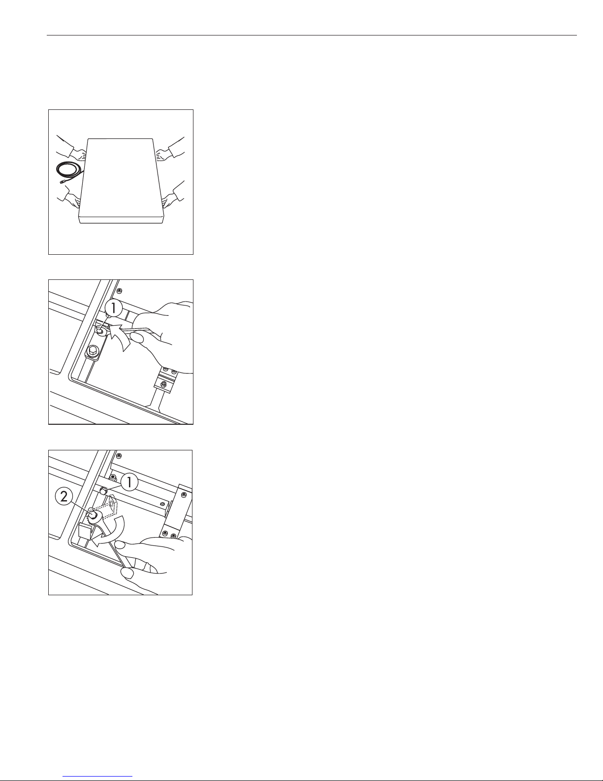
Unpacking the Platform
Important note:
These instructions apply to platforms that are 60 x 80 cm and larger.
§ Remove the weighing platform and weighing pan from the packaging.
§ When transporting or lifting the device, hold the unit on the longer sides and observe the
safety precautions (wear safety shoes and gloves if necessary).
§ Remove any plastic wrapping, packaging strips and styrofoam.
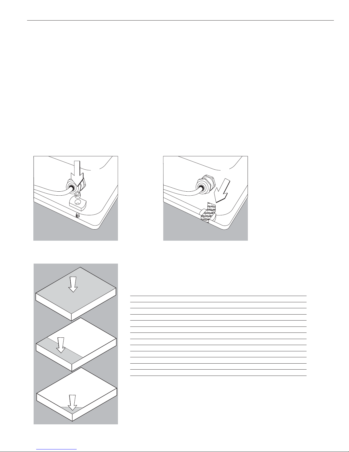
Removing the Transport Locking Device
§ Bring the scale to the location where it will be used and remove the weighing pan.
§ Loosen the transport locking device by removing screw 1.
§ Loosen screw 2, turn the fastening bracket by 180° and then tighten screw 2.
§ Tighten screw 1 again at the lever.
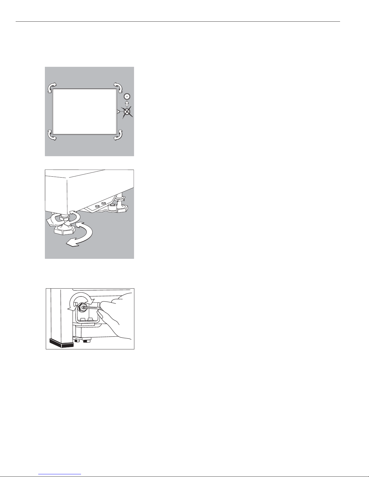
Important Note Regarding Transport of the Weighing Platform
!Be sure to refasten the transport locking device before transporting the weighing platform.
Level the weighing platform at the weighing location using the adjustable feet so that the
air bubble is centered in the level indicator circle. Check that all four adjustable feet are in
contact with the surface.
The load must be equally distributed over all four leveling feet.
6
7
Leveling the Weighing Platform
Purpose:
– To compensate for uneven areas at the
place of installation
– To ensure that the equipment is placed
in a perfectly horizontal position for
consistently reproducible weighing
results
Always level the weighing platform
again any time after it has been moved
to a different location.
§ Level the weighing platform using the
four leveling feet. Turn the feet until
the air bubble is centered in the level
indicator.
§ Check to ensure that all four leveling
feet rest securely on the work surface.
> The load must be equally distributed
over all four feet
§ Loosen the lock nuts on the leveling
feet using a open-end wrench
(spanner).
> Adjusting the leveling feet:
To raise the weighing platform, extend
the leveling feet (turn clockwise).
To lower the weighing platform, retract
the leveling feet (turn ounterclockwise).
§ After leveling the weighing platform,
tighten the lock nuts as follows:
Small platforms (1 load cell): against the
platform frame
Large weighing platforms (4 load cells):
against the platform foot
§ Remove the load plate
§ Loosen the locknuts on the leveling feet
using a 17 mm open-end wrench
(spanner)
> Small platforms (1 load cell):
against the platform frame
Large weighing platforms (4 load cells):
against the platform foot
§ Extend or retract the leveling feet using
a 5 mm Allen wrench (key)
§ After leveling the weighing platform,
refasten the locknuts securely against
the platform frame
§ Replace the load plate
Checking the Geographical Data
Entered for Use in Legal Metrology
(for CW* Models Only):
Preparation
(See also the “Device Information”
menu items listed under “Operating
Menu Overview” in the chapter entitled
“Configuring the Combics”.)
§ Press e to turn on the Combics
§ Activate the Setup program:
Press the M key
> SETUP is displayed
§ Select “Device-specific information”:
Press the q soft key repeatedly;
press the O soft key to confirm
§ Specify WP1 or WP2 for the weighing
platform in question:
Press the q soft key repeatedly;
press the O soft key to confirm
> View geographical data (configured
prior to verification), for example:
Latitude (in degrees): 51
4
Elevation (in meters): 513
5
or
Gravitational acceleration
(in m/s
2
: 9.810
6
The scale can be used in legal metrology
anywhere in Germany if the
geographical data is as follows:
– Latitude: 51.00 degrees
– Elevation: 513 m
This data corresponds to the following
value:
– Gravitational acceleration: 9.810 m/s
2
These values are calculated for Germany
based on a mean value for the Earth’s
acceleration. The greater the precision
of the geographical data entered, the
greater the precision achieved with the
weighing instrument; the tolerance
range, however, is restricted accordingly
(see above).
The tolerances ranges, for example
for a scale with 3000 e, are as follows:
– ± 100 for the latitude, and
– ± 200 for the elevation above sea level.
!If used outside the specified zone,
the scale must be re-verified for use in
legal metrology. Please contact an
authorized service technician.
Indicators Verified for Use in Legal
Metrology in the EU*
EU legislation requires that a control
seal be affixed to the verified device.
The control seal consists of a sticker
with the “Sartorius” logo. This seal will
be irreparably damaged if you attempt
to remove it. If the seal is broken, the
validity of the verification becomes null
and void, and you must have your scale
re-verified.
* including the Signatories of the
Agreement on the European Economic
Area

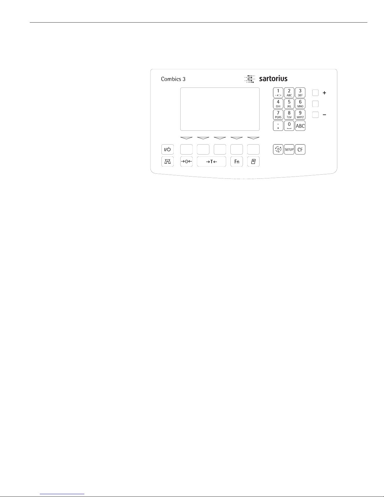
1 Load plate
2 Leveling feet
3 Level indicator
4 LEDs for checkweighing and
classification
5 Toggle to alphabetical input
6 Alphanumeric keypad
7 CF key (clear function)
8 Settings:
Access Setup program
9 Toggle to the application program |
application-specific information
10 Data output key
11 Gross/net; 2nd unit or 10x higher
resolution (depending on the
settings)
12 Tare key
13 Zero key
14 Toggle to different weighing
platform
15 On/off key
16 Function keys
17 Graphic-capable dot-matrix display
Rear View
18 COM2 | UniCOM interface
19 COM1: RS-232 interface
20 Power cord with country-specific
plug
21 Menu access switch (standard
operating mode or legal metrology
mode)
22 Connector for weighing platform
23 Vent valve; torque: 1.5 Nm
8
General View of the Equipment
Combics 3
Rear view: CW3P models
Rear view: CW3S | CW3FS | CH3E | CH3G
17
16
15
14
13
12
11
10
22
21
18
23
22
21
1
2
3
2
4
5
6
7
8
9
18
19
20
19
20
Connecting the Combics to AC Power
§ Check the voltage rating and the plug design.
$ The scale is powered through the pre-installed power cord. The power supply is built in
to the scale, which can be operated with a supply voltage of 100V to 240V.
Make sure that the voltage rating printed on the manufacturer’s ID label is identical to
that of your local line voltage. If the voltage specified on the label or the plug design of
the AC adapter do not match the rating or standard you use, please contact your Sartorius
office or dealer.
The power connection must be made in accordance with the regulations applicable in
your country.
§ To power a protective class 1 device, plug the power cord into an electrical outlet (mains
supply) that is properly installed with a protective grounding conductor (protective earth
= PE).
Safety Precautions
If you use an electrical outlet that does not have a protective grounding conductor
(protective earth), make sure to have a certified electrician install equivalent protection
according to the installation requirements valid in your country. Make sure the protective
grounding effect is not neutralized by use of an extension cord that lacks a protective
grounding conductor.
Connecting Electronic Peripheral Devices
§ Make absolutely sure to unplug the scale from AC power before you connect or
disconnect a peripheral device (printer or PC) to or from the interface port.
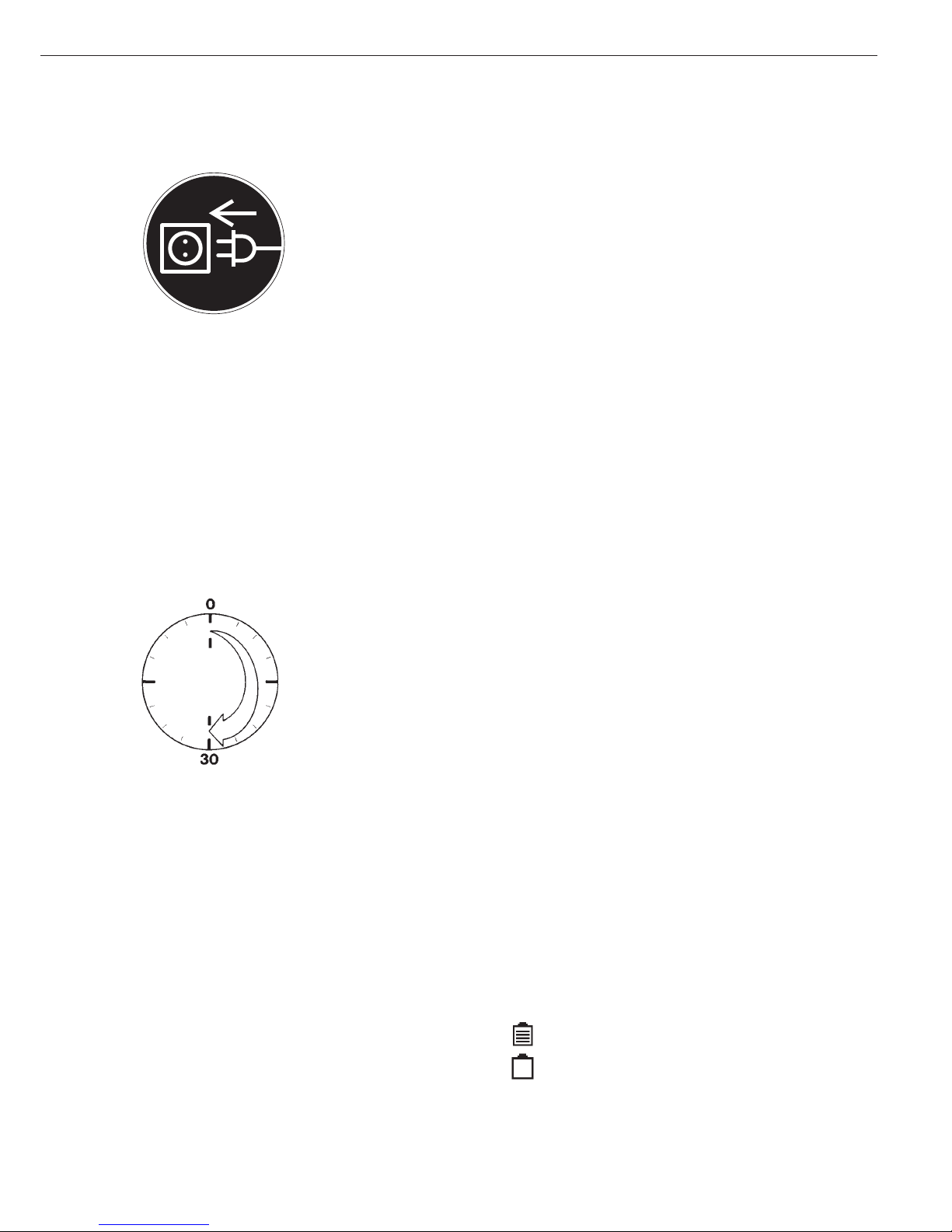
Warmup Time
To deliver exact results, the scale must warm up for at least 30 minutes after initial
connection to AC power or after a relatively long power outage. Only after this time will
the scale have reached the required operating temperature.
Using Equipment Verified as Legal Measuring Instruments in the EU*
$ Make sure to allow the equipment to warm up for at least 24 hours after initial
connection to AC power or after a relatively long power outage.
Connecting the External Rechargeable Battery Pack (Accessory YRB10Z)
!Disconnect the equipment from AC power (unplug the AC adapter)
§ Installation
CW3P models: Connect a 25-pin D-Sub male connector (connecting cable YCC02-RB01)
to the COM2 port
CW3.S models: Please see “Pin Assignment Charts” in this manual
(implemented via the YCC02-RB02 connecting cable or as Option L2)
Operation
– Hours of operation: up to 40, depending on the weighing platform connected; without
options. The Combics automatically switches to battery operation whenever there is a
power shortage or the power is cutoff. Once the mains power supply is restored, the
Combics automatically switches back to normal operation.
Battery symbol
Battery fully loaded:
Battery empty:
* including the Signatories of the Agreement on the European Economic Area
9
Connecting a Bar Code Scanner (Accessory YBR02CISL)
!Disconnect the equipment from AC power (unplug the AC adapter)
§ Installation
For model CW3P:
– Connect a 25-pin D-Sub male connector to the COM 2 (UniCOM) port
– To connect both a bar code scanner and an external rechargeable battery, please use the YTC01 T-connector.
For model CW3S: please see “Pin Assignment Charts” in this manual (implemented via the YCC02-BR02 connecting cable or as Option M8)
Installing the Verification Adapter for Use in Legal Metrology (on verifiable models only)
§ Remove the nut located on the back of the indicator
§ Use the slotted screw to install the adapter plate § Affix the verification seal over the adapter
10
Operating Tolerances
Never exceed the maximum capacity of the weighing platform.
The maximum loading capacities of the weighing platforms are listed
in the table below, and depend on the position of the load on the platform:
Platform size Center Side Corner
320 + 240 50 35 20
400 + 300 130 85 45
500 + 400 300 200 100
500 + 400 (P*) 600 400 200
650 + 500 (S**) 450 300 150
800 + 600 (P*) 1200 800 400
800 + 600 (S**) 900 600 300
800 + 800 4500 3000 1500
1000 + 800 4500 3000 1500
1000 + 1000 4500 3000 1500
1250 + 1000 4500 3000 1500
1500 + 1250 4500 3000 1500
1500 + 1500 4500 3000 1500
2000 + 1500 4500 3000 1500
* Steel
** Stainless Steel

11
For CH3E models:
Platform dimensions: 300 x 400 Loading capacity (center) in kg: 130
For CH3G models:
Platform dimensions: 560 x 450 Loading capacity (center) in kg: 130
Platform dimensions: 800 x 600 Loading capacity (center) in kg: 600
Shock Resistance
The weighing platform features a rugged construction, but you should not allow objects
to fall onto the weighing pan. Also avoid bumps to the side of the unit and shocks.
The weighing platform withstands the loads specified in standard DIN 1EC68, Part 2-27.
Important Note About Planning Structures for Attachment to the Weighing Platform
The weighing platform is suitable for installation in systems. The scale drawings should
be used as the basis for selecting any necessary structures to be affixed to the platform.
Use the YAS041S fastening set to secure the weighing platform.
Moving or rotating parts on the weighing pan must be designed so that they do not
influence the weighing results. For example, rotating parts must be balanced. The
weighing pan must have clearance on all sides to prevent any falling objects or dirt from
creating a connection between the weighing platform and any permanent structures.
Cables and hoses between the weighing platform and other devices must not exert any
force on the weighing platform. These cables must not touch the weighing pan.
(For CW* models only):
When setting up systems in hazardous areas (zone 2 or 22), be sure to observe and
comply with the relevant regulations (e.g., EN60079-14).
Pay special attention that electrostatic charges resulting from moving parts
(e.g., conveyors) are avoided or discharged.
Preload Range (Zero-Point Range)
The weight of any structures that are permanently mounted on the weighing platform
constitutes the “preload.” The preload is electronically compensated in the weighing
platform so that the entire weighing range is available and so that the scale can be zeroed
or calibrated (using external weights).
Larger preloads will lead to a reduction of the weighing range. The weight on the scale
may not fall below the following weighing range values:
– At least 30 kg of the weighing range must remain for models CH3G-150 1G-H
– At least 60 kg of the weighing range must remain for models CH3G-300 1G-H
!You must always set the preload prior to verifying the scale for legal metrology.
All structures must be mounted on the weighing platform before it is connected to AC
power.
With Combics 3 you can
– collect weight values from two
weighing platforms
– use application programs to calculate
and display results
– assign codes to identify the samples
weighed
Before you begin, you need to configure
your Combics complete scale for your
requirements. This is achieved by
setting parameters in the operating
menu (for example, to configure a
connected printer). You can then begin
operation, with functions active for
storing and calculating weighing data.
The description of the operating design
is divided into the following sections:
– Data Input
– Display Modes
– Error Codes
– Data Output
– Saving Data
Data Input
There are a number of options for
entering data:
– Through the indicator keypad (e.g., with
the 0, 1, 2... 9 keys)
– Through the weighing platform (e.g.,
tare values)
– Through the digital input/output
interface
– Through the COM port
– Through a bar code scanner or external
keyboard
Keypad Input
Labeled Keys
These keys always have the function
indicated by the label, but the functions
might not be available at all times.
Whether a function is available at a
given time depends on the operating
state of the scale and the menu settings
active at that time. Some of the keys
have a second function, activated by
pressing and holding the key for longer
than 2 seconds.
e On/off key
Turn the Combics on and off or
switch it to the standby mode. In
standby mode, the display shows
OFF.
n Toggle the display between
connected weighing platforms.
With two weighing platforms
connected, this key toggles the
display between the two readouts.
( – Zero the scale
– Cancel a calibration/adjustment
procedure
) – Press briefly (< 2 sec):
Tare the weighing platform
– Press and hold (> 2 sec ):
Activate calibration/adjustment
k Toggles the display between:
– first and second weight unit, or
– gross and net values, or
– normal and 10-fold higher
resolution,
depending on your settings in the
operating menu.
p – Press briefly:
Print
– Press and hold:
Print GMP footer
D – Press and hold:
Toggle to info mode (only when
an initialized application is active)
M – Access to Setup program
– Exit the Setup program
c – Press briefly:
Quit application program, delete
input character
– Press and hold:
Delete entire input string
0, 1, 2... 9, .
Enter numbers, letters and other
characters
a Toggle between numeric and
alphabetic input
12
Operating Elements: Combics 3
Operating Design
13
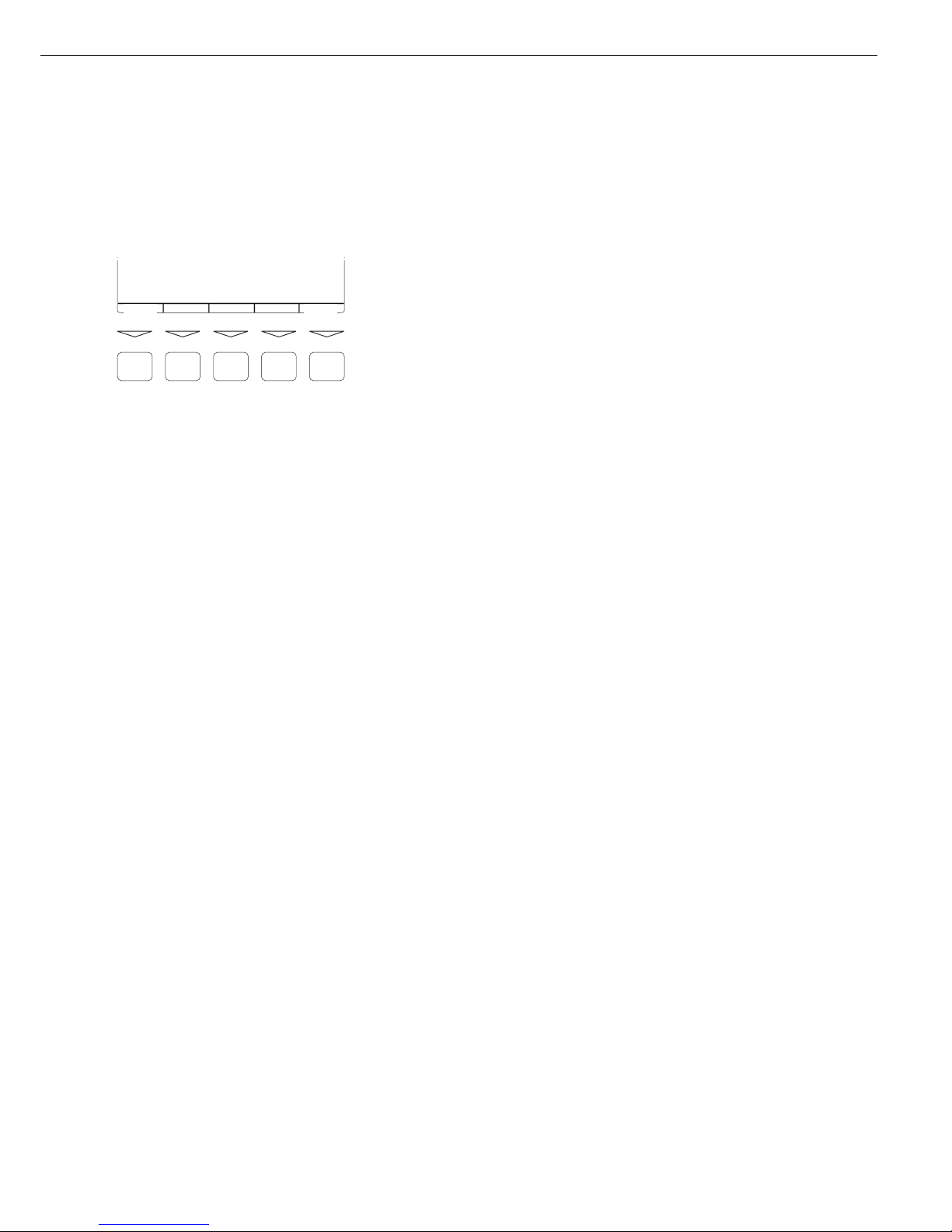
Function Keys (Soft Keys)
The current function of a given soft key
is indicated in the last line on the display
(footer). Functions are indicated by
abbreviated texts or symbols .
Texts (Examples)
1st ID: Store the first ID line
ESC: Cancel input
Symbols in the footer:
oo: Return to initial state
o: Go one level higher
o: Show items under selected entry
Q: Move up one position in I/O window
q: Move down one position in
I/O window
l: Confirm selected parameter setting
F5 F4 F3
F2
F1
1st ID ESC
Numeric Input Through the Keypad
§ Enter numbers one digit at a time:
Press 0, 1, 2... 9 as needed
§ Store input:
Press the required key (e.g., press )
to store manual tare input)
$ Deleting a digit:
Press c briefly
$ Deleting entire input string:
Press and hold c (> 2 sec)
Text Input Through the Keypad
§ Press the a key
> ‘ABC’ is displayed
§ Press the key on which the desired letter
is printed repeatedly, until that letter
is displayed (please note that keys can
activate other characters in addition to
those shown on the key)
$ If the next letter or character you wish
to enter is activated by the same key as
the previous character, press the
l soft
key or wait 2 seconds before entering
the next character.
$ Entering a space: Press the 0 key
$ Entering punctuation or special
characters:
Press the 1 key or . key repeatedly
until the desired character is displayed,
and then press the
l soft key to insert
it in the string.
$ Deleting characters: Press c briefly
$ Deleting entire input string:
Press and hold c (> 2 sec)
$ Exit text input mode and return to
numeric input mode: Press the a key
> 123 is displayed
§ Store input:
Press the required soft key
(for example,
1st ID)
Input Through the Weighing Platform
You can store the weight on the
weighing platform; for example,
as a tare weight (press the ) key)
Input Through the Digital I/O Port
An input control line is available for
use with all application programs, for
connecting a remote hand switch or
foot switch. Configure this input line
in the Setup program, under
Device parameters Control input
to assign one of the following functions
to the remote switch:
–
Print key
– Print key - long
– Tare key
– Tare key - long
– Fn key
– WP toggle key
Input Through the COM Port
The Combics scale is equipped with
a simple ASCII interface (SBI ) for data
transfer. The functions are described
in detail in the chapter entitled
“Operating the Combics”, under
“Data Output Functions”.
14
Operating Design
Input Through a Bar Code Scanner or
External Keyboard
You can use a bar code scanner or a
keyboard to enter alphanumeric values
in the Combics. Generally, you can use
any bar code format that is compatible
with the scanner connected. Like values
entered through the keypad, barcode
and keyboard input is handled as:
– Weight values for tare memory
– Reference weight values for the
Counting, Neutral Measurement and
Weighing in Percent applications
– Numeric values
– Product identifiers
You can also configure your Combics 3
to activate a function when a particular
bar code is scanned, or to display the
value represented by the bar code
without initializing any function.
This feature is configured in the Setup
program, under:
Device parameters Bar code
Select Reference, Tare or ID1 to
use the value represented by the bar code
as a reference, tare or ID1 value.
Bar code values can include a designator
specifying that the value scanned is
designated as a tare value, for example, or
an ID4 value. If you select the menu
setting
Input without
activating function
, the
content of bar code is displayed but no
function is activated, regardless of the
designation. The next
key pressed determines which function is
to be activated (e.g., “Set tare value”).
If you select
Input, the value scanned
is displayed if it has no (recognizable)
designation assigned. In this case, no
function is activated. The next key
pressed determines which function is
to be activated.
If you select
External keyboard,
you can enter data through an external
keyboard; the data is handled in the same
manner as keypad input.
Display Modes
There are two display modes: one is used
during weighing and the other when
working with the operating menu (Setup
program).
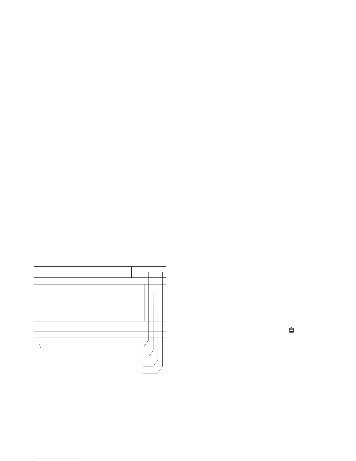
Display Mode During Weighing
(Main Display)
This display is subdivided into nine
sections.
Lines for metrological data:
These lines show:
WP1/2 Active weighing platform
R1/2 Current weighing range of
the active weighing platform
(with multiple range scale
connected)
Max Upper limit of the weighing
range in the active weighing
platform
Min Lower limit of the weighing
range in the active weighing
platform (verified models only)
e Verification scale interval
the active weighing platform
(verified models only)
d Readability/index of the active
weighing platform
Application symbols:
This field shows a symbol indicating the
selected application program (e.g.,
A for
the Counting application). The other
symbols that can be shown here include:
S Printing mode active
T GMP printing mode active
Battery symbol:
A battery symbol is shown in this field
when the Combics 3 is operated with
a remote rechargeable battery: The
symbol is filled in when the battery is
fully charged; when the battery is empty,
only an outline is shown.
Lines for metrological data
Bar graph
Text lines
Soft key labels
Line for measured values
Plus/minus sign
Stability symbol
Battery symbol
Application symbol
Unit
Tare memory/
calculated value
Info/Status line
15
Bar graph:
The bar graph shows the percentage of the
weighing platform’s capacity that is “used
up” by the load on the scale (gross value).
When the Checkweighing application is
active, the tolerance limits are also shown
(calculated value). The following symbols
may be displayed here:
0% Lower limit
100% Upper limit
Bar graph with 10% markings
Minimum for the
Checkweighing application
Target for the Checkweighing
application
Maximum for the
Checkweighing application
Plus/minus sign:
This field shows either a plus or minus sign
(
+ or -) for weight values (or calculated
values), or the
o symbol when the
weighing platform is zeroed or tared.
Measured value/result line:
This field shows weight values, calculated
values and input characters.
Unit and stability:
When the weighing system reaches
stability, the weight unit or calculation
unit is displayed here.
Tare in memory, calculated values:
A symbol here indicates that a tare value
is stored or that the result is a calculated
value.
The following symbols may be displayed
here:
a Calculated value (cannot be
used in legal metrology)
NET Net value (gross weight
minus tare)
B/G Gross value (net value
plus tare)
Text lines:
The text lines show operator support
information, such as the name of the
active program, user guidance prompts,
etc.
Soft key labels:
This line shows the abbreviations or
symbols that indicate soft key functions
Display Mode for Configuration
and Information (Setup)
This display is divided into three sections.
Line for operating status:
The operating status line indicates
the function of the current screen page.
In the Setup program, this line shows
the “path” to the information displayed
Input and output window:
This section shows detailed information
(e.g., on the selected application) or a list
of options for selection. A selected item is
displayed inversely (white letters on a black
background). You can enter letters and
numbers in active fields here.
Soft key labels:
See the description above, under “Function
Keys (Soft Keys)” (page 11).
Status line
Input/output window
Soft key labels
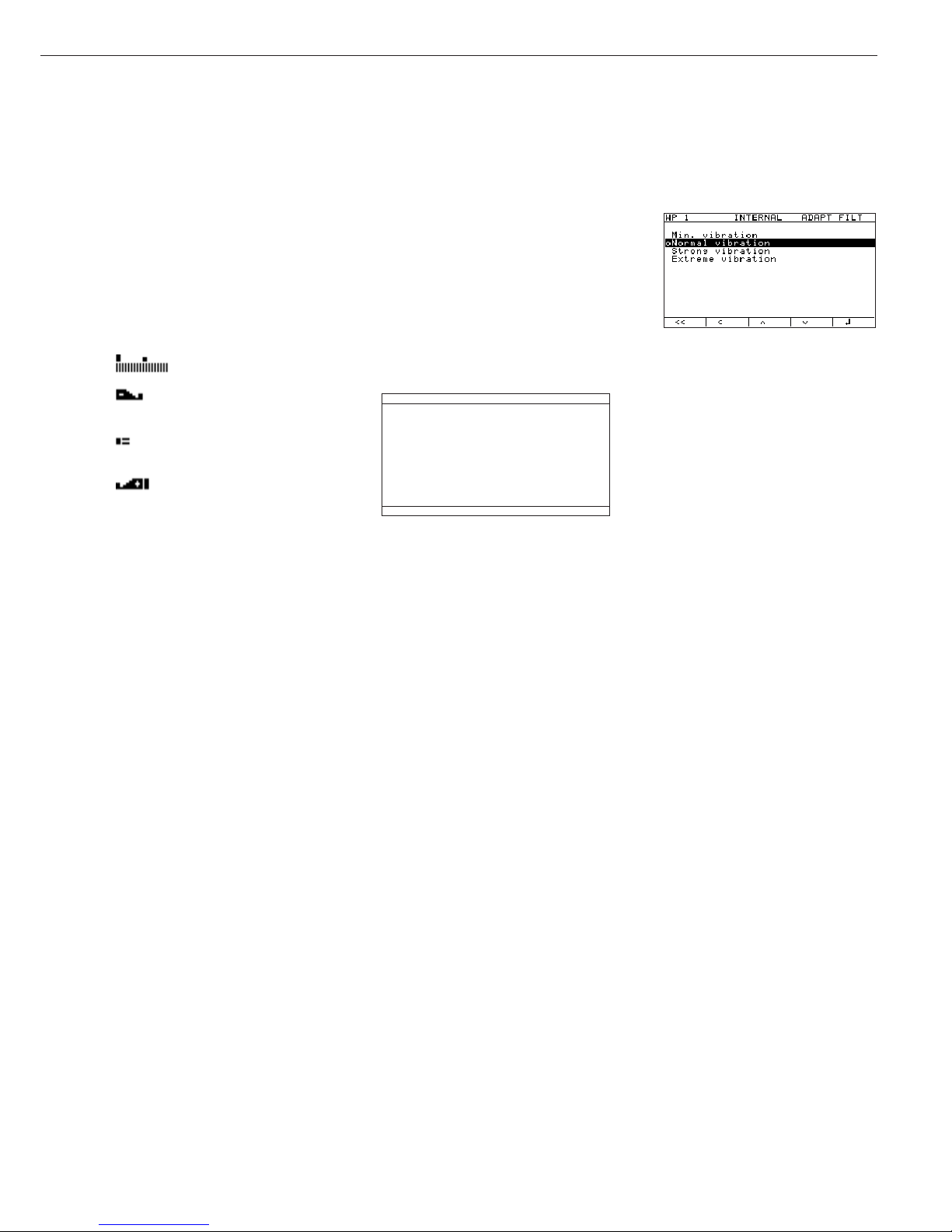
Example: Setup: Device parameters:
WP-1: Internal: Adapt filter:
o This symbol indicates the currently
active menu setting
Setting parameters:
§ Press the Q or q soft key repeatedly
until the desired parameter is selected
(inverse display)
§ Confirm the setting: Press the l soft
key
§ Exit the Setup program: Press the
M key
Error Codes
– If a key is inactive, this is indicated as
follows:
– The error code “-” and/or
“
No function” is displayed for
2 seconds. The display then returns
to the previous screen content.
– An acoustic signal (double-beep)
is emitted.
– Temporary errors are indicated by
an error code, shown in the measured
value/result line for 2 seconds (for
example,
Inf 09).
– Fatal errors are indicated by an error
code displayed steadily in the measured
value/result line (for example,
Err
101
), until you turn the Combics off
and then on again (reset).
This process is the same for all
operating modes (weighing, application
programs and Setup program).
Error codes and messages are described
in detail in the chapter entitled “Error
Codes.”

16
Operating Design
Data Output
You can choose from four forms
of data output:
– Printer
– Digital input/output interface
– COM port
– LEDs
Printer
You can connect one or two strip
printers or one or two label printers
to the Combics. If you use a universal
printer or a model YDP02 or YDP03
printer, you can configure interface
parameters in the Setup program
(baud rate, stop bits, handshake
mode, data bits).
The printout can be formatted by the
user. The printout consists of two
user-definable header lines, up to four
lines identifying the weighing data,
one line for date and time, initialization
data (only when using applications),
serial number and results. For a strip
printer, universal printer or label printer,
you can also define whether a GMP
header and GMP footer (field for
operator signature) will be included
on the printout (GMP: Good
Manufacturing Practice).
These functions are described in detail
in the chapter entitled “Operating
the Combics”, under “Data Output
Functions.”
You can have printouts generated
at the press of a key, or automatically
(dependent on stability).
For the Totalizing and Net-total
applications, you can also configure
summarized printouts (results)
independent of individual or
component value printouts.
Press the p key to print the settings
of the current menu level on a strip
printer or a universal printer.
All submenus under the current menu
level are included on the printout.
Digital Input/Output Interface
The digital I/O interface is supported
by the Checkweighing and Classification
applications.
Checkweighing
Four data outputs transfer the following
information on the weight values:
“less than”, “equal to”, “greater than”
and “set” In the Setup menu, you can
configure whether the outputs are:
always on; activated when the scale
has stabilized; active only within the
checkweighing range; activated when
the scale has stabilized only if the
values are within the checkweighing
range, or off.
Classification
Four data outputs transfer information
on the class of the load (Class 1, 2, 3,
4 or 5) and whether the minimum load
is exceeded (Set). The user can define
whether the output lines are always
active, activated only at stability, or off.
For the Checkweighing and
Classification applications, you can use
the “Set” output to indicate:
– The scale(s) and the Combics 3 indicator
are ready to operate, or
– for Checkweighing: Set
– for Classification: Minimum load
exceeded
For all other applications, the “Set”
output indicates when the Combics 3
indicator is ready to operate.
COM Port
The Combics scale is equipped
with an SBI interface for data transfer.
You can define certain parameters for
this interface (generate printout,
time-dependent autoprint, ID codes).
See “Data Output Functions” in
the chapter entitled “Operating the
Combics” for a detailed description
of data output options.
LEDs
The Combics 3 has an integrated
checkweighing display consisting
of three LEDs, for use with the
Checkweighing and Classification
applications. These LEDs show the
relationship of the current weight
value to the tolerance limits in
Checkweighing; with the Classification
application, they indicate how the
weight value is classified.
Saving Data
The parameters you select in the
operating menu remain stored after
you turn off the Combics.
The Combics also stores all application
parameters (for example, reference
values). These parameters are
overwritten only when
– you turn the Combics off and then
back on again
– you return to the originally selected
application from a different one
(for example, if you switch from
Counting to Averaging, the values
previously stored for the Counting
application are restored)
You can restrict access to the Device
parameters menu in the Setup program
by assigning a password. The password
is configured in the Setup program,
under:
Device parameters Password
Purpose
You can configure the Combics 3 to meet
individual requirements by entering user
data and setting menu parameters in the
Setup program.
17
Configuring the Combics
Features
The operating menu parameters are
divided into the following categories
(highest menu level):
– Application parameters
– Fn key function
– Device parameters
– Device-specific information (
Info)
– Language
When you use the scale in legal
metrology, access to parameters
is restricted.
Factory setting
Parameters: The factory-set
configurations are identified by an “o”
in the list starting on the next page.
Setting the Language
You can choose from five languages
for the display of information:
– German
– English (factory setting)
– English with U.S. date/time format
– French
– Italian
– Spanish
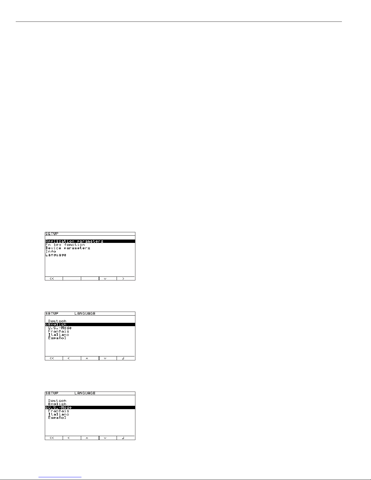
Example: Selecting “U.S. Mode” for the Language
e Turn on the Combics
M Activate the Setup program
)
Soft key q (repeatedly), Select “Language”
Soft key O and confirm
Soft key Q, Select “U.S. Mode”
Soft key l Save the new setting
Soft key oo Exit the Setup menu
18
Navigating in the Operating Menu (Examples)
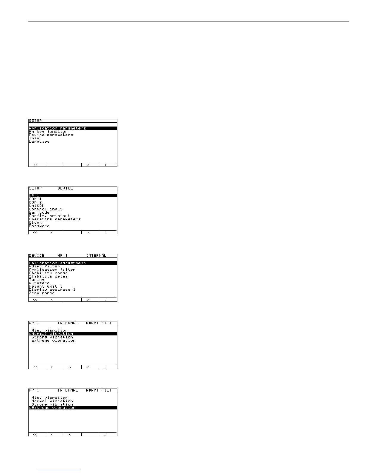
Example: Adapting the Combics to ambient conditions at the place of installation; menu item: “Very unstable conditions”
for weighing platform WP1.
e Turn on the Combics
M Activate the Setup program
Soft key q, Select
Device parameters
Soft key O and confirm
Soft key O, Confirm weighing platform
WP-1 and then
Soft key O confirm
Internal
Soft key q, Select Adapt filter
Soft key O and confirm
2+ soft key q, Select
Very unstable
Soft key l and save
To continue: soft key o Change other menu settings if desired, or
Soft key oo Exit the Setup menu
19
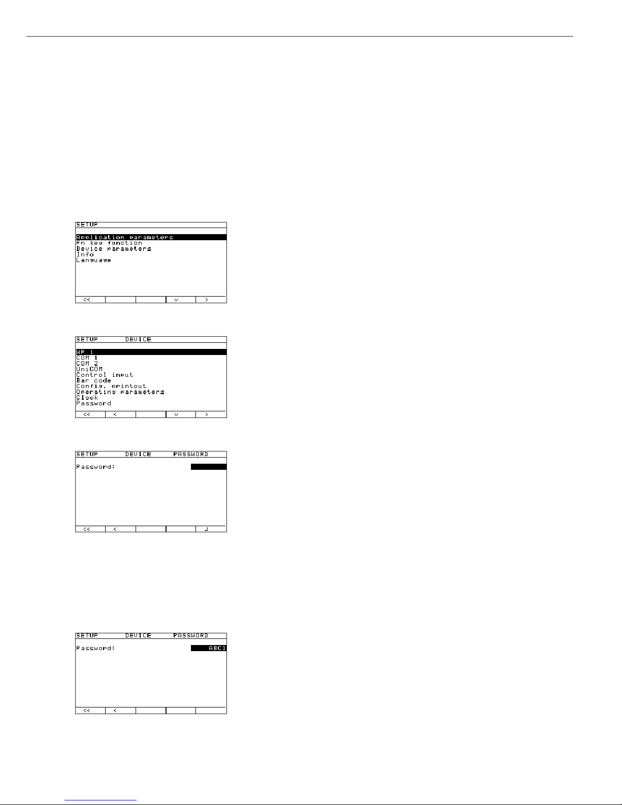
Defining Password Protection for the Operating Menu: Entering, Changing or Deleting a Password
You can define a password to protect the
Application parameters and Device parameters. To do this, enter a password
known only to authorized personnel. Without the password, only a few of the menu items can be accessed (k key, Info, language).
Example: Entering, changing or deleting the password “ABC1”
e Turn on the Combics
M Activate the Setup program
2+ soft key q, Select
Device parameters
Soft key O and confirm
Soft key q repeatedly, Select
Password
Soft key O and confirm
a, 2(ABC), Soft key l; Enter password: “ABC1” (max. 8 characters)
2+
2(ABC), Soft key l; Confirm input (wait 2 seconds or press l soft key)
3+
2(ABC), Soft key l; Confirm password
a, 1, Soft key l If necessary: delete password:
Press c and confirm with soft key l
To continue: soft key o Change other menu settings if desired, or
Soft key oo Exit the Setup menu

20
Printing Parameter Settings
To generate a printout of the settings
on the current menu level:
Press the p key
> Printout (example)
The maximum width of this printout
is 20 characters.
--------------------
12.01.2002 09:46
Model CW3P1-6ED-LCE
Ser.no. 12345678
Vers. 1.1010.10.2
BVers. 01-26-01
-------------------SETUP
DEVICE
--------------------
WP-1
Internal
COM1
Data communication
SBI
Baud rate
1200 baud
Parity
Odd
Number of stop b
1 stop bi
Handshake mode
Hardware 1 charact
Number of data b
7 bit
Data output
Printout, printer 1
Line format
For other apps. (22
characters)
COM2
Off
UNICOM
Off
Control input
Print key
Bar code
Reference val
Printout
Headers
Line 1:
Line 2:
ID codes
ID1:
123
ID2:
456
ID3:
ID3
ID4:
ID4
ISO/GLP/GMP
Off
Date/time
Date with time
Once at stability
Off
etc.

21
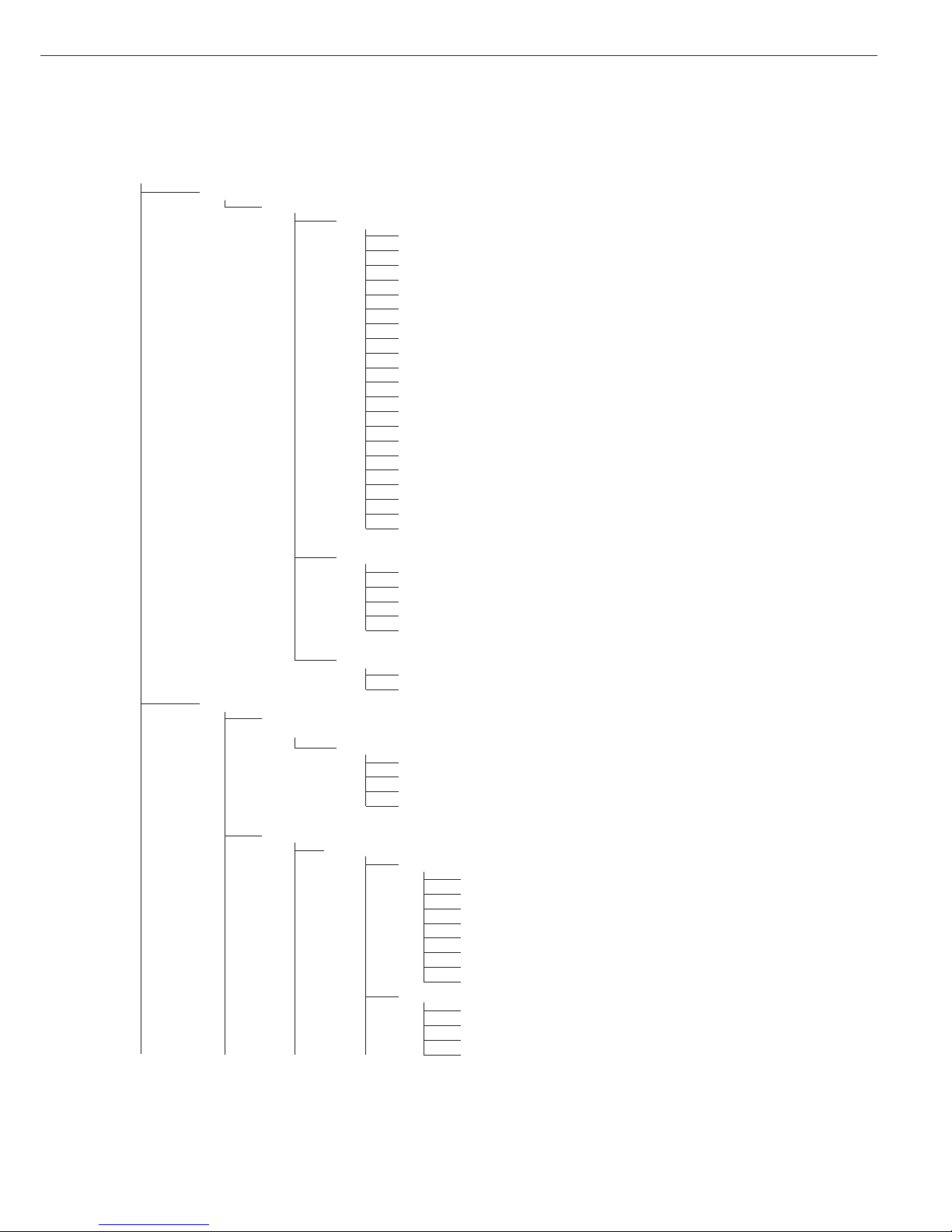
Operating Menu Overview (Parameters)
o = Factory setting
W User-defined setting
Setup
Application parameters: Please refer to the operating instructions for Combics 3 “Basic Application Programs”
Fn-key
Off
o Gross/net toggling
Toggle weight units
10 + higher resolution
Device Parameters
WP-1
Off
RS-232
1
)
SBI standard
SBI verifiable
o IS-232
ADC-232
Internal
Calibration/Adjustment
CAL Key Function
o Ext. cal./adjust.; default weight
Ext. cal./adjust.; weight can be selected
Key blocked
Calibration/Adjustment Sequence
Calibration with automatic adjustment
o Calibration with adjustment triggered manually
isoCAL Function
o Off
Adjustment prompt
External Calibration/Adjustment
2
)
o Accessible
Blocked
External Weight
Cal./adj. weight
Adapt Filter
Min. vibration
o Normal vibration
Strong vibration
Extreme vibration
Application Filter
o Final readout
Filling mode
Low filtering
W/o filtering
Stability Range
1/4 digit
1/2 digit
o 1 digit
2
)
2 digits
2
)
4 digits
2
)
8 digits
2
)
1
) = function will be made available in future
2
) = not available on scales verified for use in legal metrology

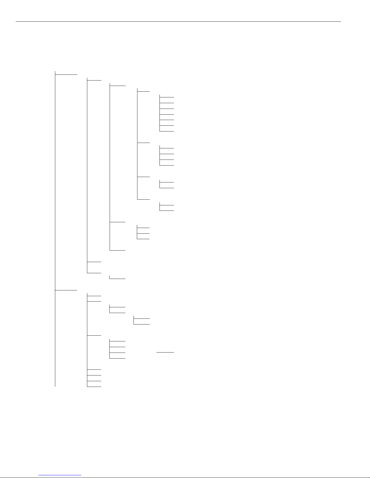
22
Device Parameters
WP-1
Internal
Stability Delay
No delay
o Short delay
Average delay
Long delay
Taring
1
)
Without stability
o After stability
Auto Zero
oOn
Off
Weight Unit 1
2
)
User-defined / o (factory setting: grams
1
)
Grams / g
o Kilograms / kg
Carats / ct
1
)
Pounds / lb
1
)
Ounces / oz
1
)
Troy ounces / ozt
1
)
Hong Kong taels / tlh
1
)
Singapore taels / tls
1
)
Taiwanese taels / tlt
1
)
Grains / GN
1
)
Pennyweights / dwt
1
)
Milligrams / mg
1
)
Parts per pound / lb
1
)
Chinese taels / tlc
1
)
Mommes / mom
1
)
Austrian carats / K
1
)
Tola / tol
1
)
Baht / bat
1
)
Mesghal / MS
1
)
Tons / t
Display Accuracy 1
o All digits
Reduced by 1 decimal place for load change
Index +1
1
)
Index +2
1
)
Reduced by 1 decimal place
1
)
Zero Range
1 percent/max. cap.
o 2 percent/max. cap.
Zero at Power On
2 percent/max. cap.
o 5 percent/max. cap.
Tare/Zero at Power On
oOn
Off
Only zero at power on
1
) = not available on scales verified for use in legal metrology
2
) = depends on weighing platform model
23
Device Parameters
WP-1
Internal
Weight Unit 2
2
)
User-defined / o (factory setting: grams
1
)
o Grams / g
Kilograms /kg
Carats / ct
1
)
Pounds / lb
1
)
Ounces / oz
1
)
Troy ounces / ozt
1
)
Hong Kong taels / tlh
1
)
Singapore taels / tls
1
)
Taiwanese taels / tlt
1
)
Grains / GN
1
)
Pennyweights / dwt
1
)
Milligrams / mg
1
)
Parts per pound / lb
1
)
Chinese taels / tlc
1
)
Mommes / mom
1
)
Austrian carats / K
1
)
Tola / tol
1
)
Baht / bat
1
)
Mesghal / MS
1
)
Tons / t
Display Accuracy 2
o All digits
Reduced by 1 decimal place for load change
Index +1
1
)
Index +2
1
)
Reduced by 1 decimal place
1
)
Factory Settings: Weighing Parameters
Yes
oNo
COM1
o Off
WP-2
o RS-232
SBI standard version (9600 baud)
SBI for legal metrology (9600 baud)
o IS-232
1
)
ADC-232
1
)
Data Communications
o SBI
Baud Rate
150 baud
300 baud
600 baud
o 1200 baud
2400 baud
4800 baud
9600 baud
19,200 baud
Parity
Space
3
)
o Odd
Even
None
4
)
1
) = not available on scales verified for use in legal metrology
2
) = depends on weighing platform model
3
) = not with 8 data bits
4
) = not with 7 data bits

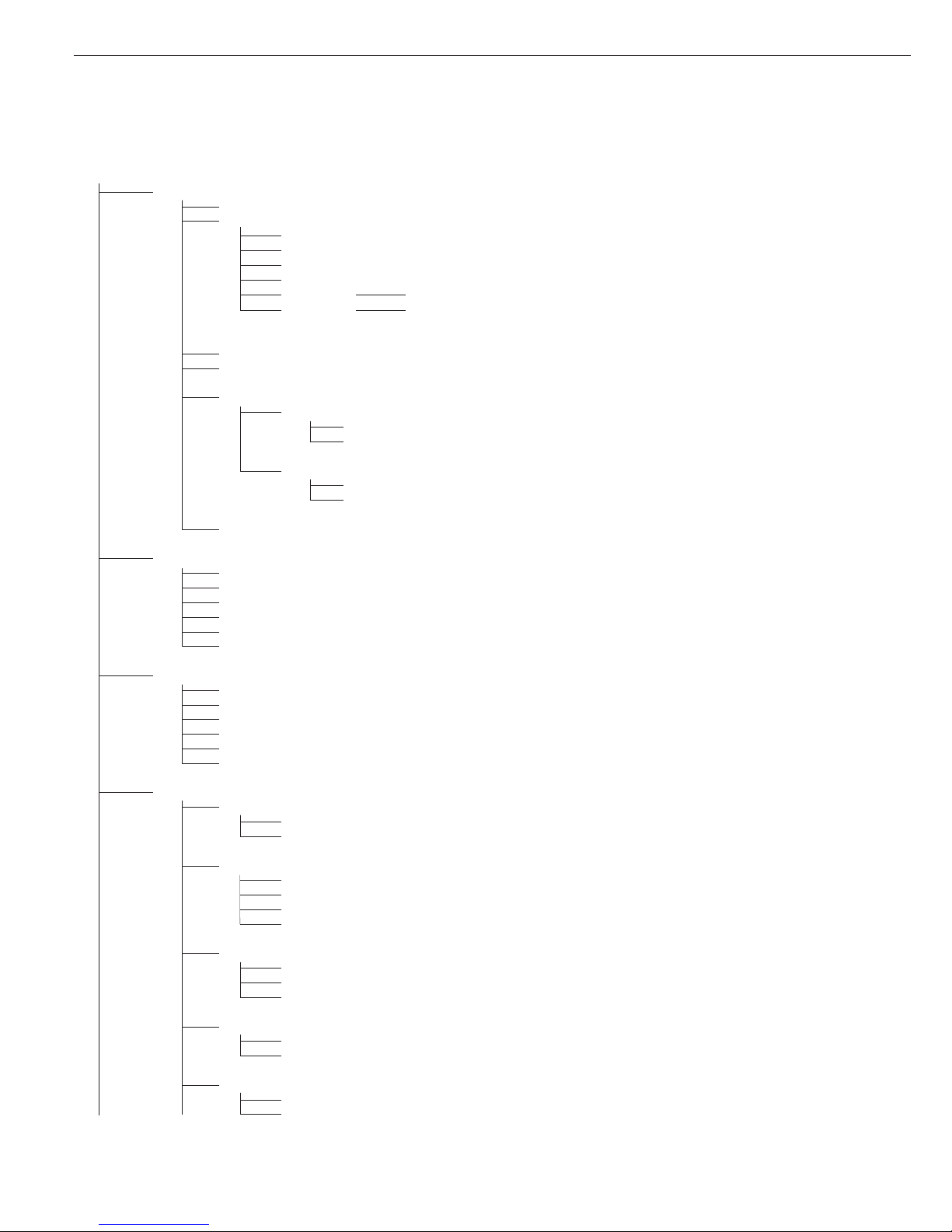
24
Device Parameters
COM1
Data Communications
o SBI
Number of Stop Bits
o 1 stop bit
2 stop bits
Handshake Mode
Software handshake
o Hardware, 1 character after CTS
Number of Data Bits
o 7 bits
8 bits
Data Output
On request, without stability
o On request, after stability
Automatic, without stability
o 1 display update
2 display updates
10 display updates
100 display updates
Automatic, at stability
o 1 display update
2 display updates
10 display updates
100 display updates
Printout, printer 1
Printout, printer 2
Line Format
For raw data (16 characters)
o For other apps. (22 characters)
Factory Settings
Yes
oNo
xBPI-232
MP8 (binary)
Application Program
MP8: 3-1-1
MP8: 3-1-2
MP8: 3-1-3
MP8: 3-1-4
MP8: 3-1-5
MP8: 3-1-6
MP8: 3-1-7
MP8: 3-1-8
MP8: 3-1-9
MP8: 3-2-1
MP8: 3-2-2
MP8: 3-2-3
MP8: 3-2-4
MP8: 3-2-5
MP8: 3-2-6
MP8: 3-2-7
MP8: 3-2-8
MP8: 3-2-9

25
Device Parameters
COM1
Data Communications
MP8
Application Program
MP8: 3-3-1
MP8: 3-3-2
MP8: 3-3-3
MP8: 3-3-4
MP8: 3-3-5
MP8: 3-3-6
MP8: 3-3-7
MP8: 3-3-8
MP8: 3-3-9
Program Code 2
o Code 2.1
Code 2.2
Code 2.3
Code 2.4
Baud Rate
150 baud
300 baud
600 baud
o 1200 baud
2400 baud
4800 baud
9600 baud
Parity
Mark
Space
o Odd
Even
Print in Weigh Mode
Manual without stability
o Manual with stability
Automatic without stability
Automatic at stability
SMA
Baud Rate
150 baud
300 baud
600 baud
1200 baud
2400 baud
4800 baud
o 9600 baud
19,200 baud
Parity
Space
1
)
Odd
Even
o None
2
)
Number of Stop Bits
o 1 stop bit
2 stop bits
1
) = not with 8 data bits
2
) = not with 7 data bits

26
Device Parameters
COM1
Data Communications
SMA
Handshake Mode
Software handshake
o Hardware, 1 character after CTS
Number of Data Bits
o 8 bits
Printer 1
1
)
YDP01IS
o Strip
Label
Label, manual form feed
YDP02
Baud Rate
o 1200 baud
2400 baud
4800 baud
9600 baud
Parity
Space
o Odd
Even
Number of Stop Bits
o 1 stop bit
2 stop bits
Handshake Mode
Software handshake
o Hardware, 1 character after CTS
YDP03
Baud Rate
o 1200 baud
2400 baud
4800 baud
9600 baud
19,200 baud
Parity
Space
oOdd
Even
Number of Stop Bits
o 1 stop bit
2 stop bits
Handshake Mode
Software handshake
o Hardware, 1 character after CTS
YDP02IS
o Strip
Label
1
) = max. 2 printers can be configured
27
Device Parameters
COM1
Printer 1
4
)
Universal
Baud Rate
150 baud
300 baud
600 baud
1200 baud
4800 baud
o 9600 baud
19,200 baud
Parity
Space
1
)
Odd
Even
o None
2
)
Number of Stop Bits
o 1 stop bit
2 stop bits
Handshake Mode
o Software handshake
Hardware, 1 character after CTS
o YDP04IS
o Strip
Label
Label, manual form feed
YAM01IS (external data logger)
Printer 2
4
) as for Printer 1
External Alibi Memory
o YAM01IS
COM2
Off
WP-2
RS-232: as for COM1
o RS-485
o IS-485
ADC-485
Data Communications
o SBI: as for COM1
xBPI-232: as for COM1
xBPI-485 Valid addresses: 0 to 31 inclusive; factory setting: 0
SMA: as for COM1
Printer 1:
4
) as for COM1
Printer 2:
4
) as for COM1
External Alibi Memory: as for COM1
External Multi-I/O Converter
3
)
1
) = not with 8 data bits
2
) = not with 7 data bits
3
) = function will be made available in future
4
) = max. 2 printers can be configured
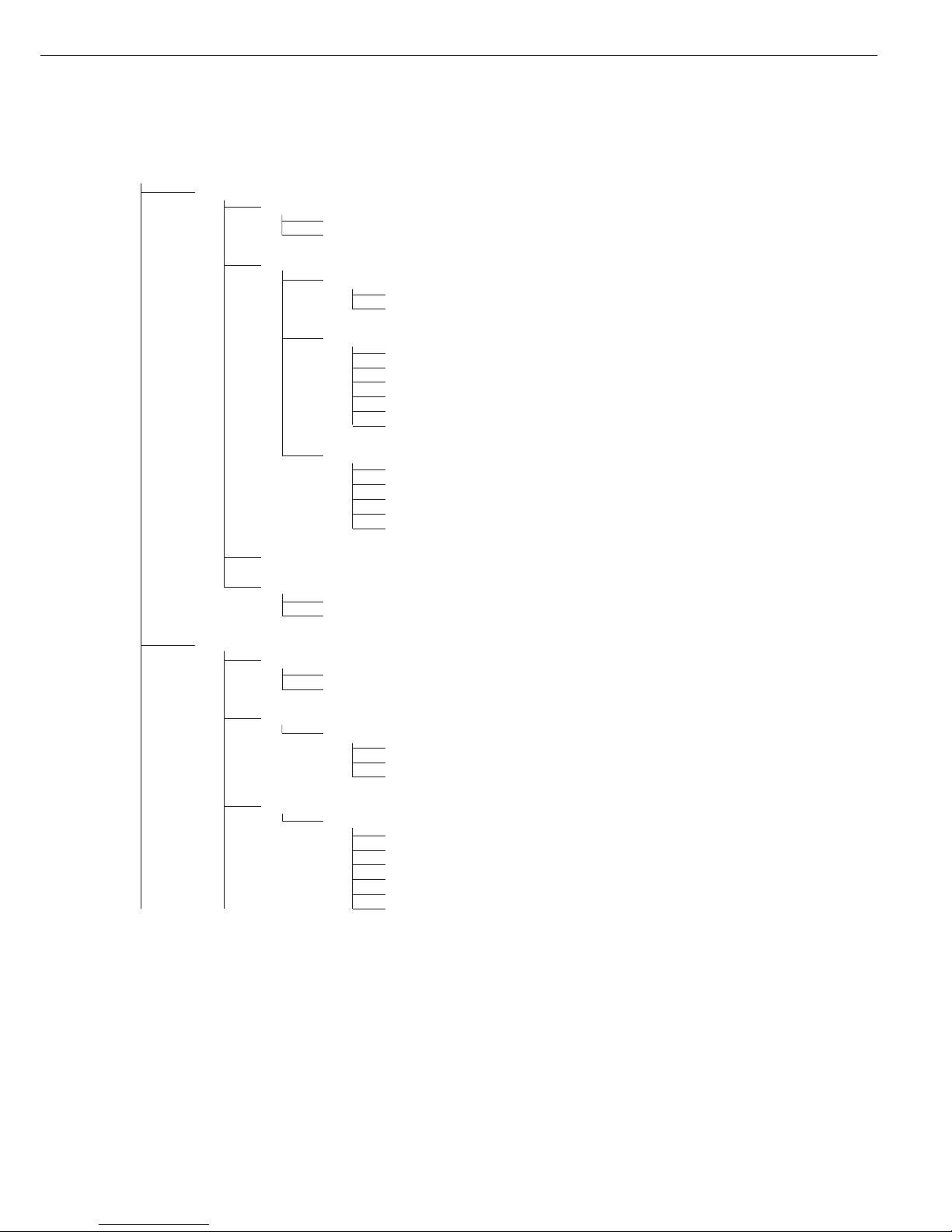
28
Device Parameters
UniCOM (Optional Interface)
o Off
Data Communications: as for COM1, plus:
o SBI: as for COM1
xBPI-232: as for COM1
xBPI-485: as for COM2
SMA: as for COM1
Profibus Valid addresses: from 0 to 126 inclusive; factory setting: 126
Ethernet Optional: Ethernet (for details, see the “Combics UNICOM Interfaces”
installation instructions included in this manual)
Printer 1:
1
) as for COM1
Printer 2:
1
) as for COM1
Analog Output Port
Value Output
o Net value
Gross value
Error Signal
o High (20 mA)
Low (0/4 mA)
External Alibi Memory: as for COM1
Control Input (for Remote Switch)
o Print key p
Print key p - long
Tare key )
Tare key ) - long
Fn key k
WP toggle key n
Bar Code
o Reference value
Tare value
ID1
Data input
Input without activating a function
External keyboard
Printout
Headers
Line 1:
Line 2:
ID Codes
ID1:
ID2:
ID3:
ID4:
ISO/GLP/GMP-compliant Printout
o Off
For 1 application result
For several application results
Date/Time
o Date with time
Date only
Once at Stability
o Off
On
1
) = max. 2 printers can be configured
29
Device Parameters
Printout
FlexPrint
o Off
On
Printer 1
Number of Printouts
o 1 printout
2 printouts
Components/Individual Printout
o Headers 1, 2
o ID1, ... ID4
o Date and time
o Application ini data
o Scale ID (e.g., serial no.)
o Application result
Printout of Result/Total
o Headers 1, 2
o ID1 through ID4
o Date and time
o Scale ID (e.g., serial no.)
o Application result
Printer 2:
1
) as for Printer 1
Factory Settings
Yes
o No
Operating Parameters
Acoustic Signal
o On
Off
Keypad
Block Key Functions
o All keys unblocked
All blocked except Setup, I/O
Alphanumeric keys blocked
Display
Contrast
1
2
3
o4
5
6
1
) = max. 2 printers can be configured
 Loading...