

Sartorius Cubis MSU116P, Cubis MSU36P, Cubis MSU36S, Cubis MSU66S, Cubis MSU66P User Manual
Page 1

User Manual
Sartorius Cubis® Series
Electronic Semimicro Micro, Precision and Analytical Balances
MSU Models
Page 2

2 Cubis® MSU User Manual
Contents
Contents
Notes on Using This Manual...................... 3
Safety Instructions ........................... 4
Intended Use . . . . . . . . . . . . . . . . . . . . . . . . . . . . . . 6
General View of the Equipment and Equipment
Supplied ................................... 6
Getting Started .............................. 11
Unpacking the Equipment .................... 11
Assembly .................................15
Installation Instructions ...................... 23
Power Connection .......................... 24
Anti-theft Locking Device..................... 26
Leveling.................................. 26
Switching On ..............................27
Removing the Retainer with the Display and
Control Unit............................... 28
Below-balance Weighing ..................... 33
Cable Opening of the Manual Analytical Balance
Draft Shield ................................. 36
Moving the Balance .......................... 37
Using the Balance ............................ 38
Turning the Balance On/Off ................... 38
Operating Design: Q-Guide.................... 38
Using the Display and Control Unit.............. 39
Setting the Language ........................40
Quick Guide: First Weighing ................... 40
Display in Operating Mode ...................41
Display in Setup Mode ....................... 42
Activating/Switching Users .................... 44
System Settings (Menu) ....................... 45
Leveling the Balance (Q-Level) ................. 46
Calibration/Adjustment Data ..................47
Configure Timer Controlled Actions .............48
Displaying Device Information ................. 50
Alibi Memory ..............................51
Device Parameters .......................... 54
Task Management ........................... 67
Using Applications with the Factory Settings....... 68
Creating New Tasks (Configuration) ............. 68
Configuring Printouts........................ 71
Combining Applications into One Task ........... 77
Executing Tasks ............................ 78
Weighing................................... 79
Mass Unit Conversion ......................... 80
SQmin Minimum Weighing ..................... 83
Individual Identifiers ..........................85
Density Determination......................... 88
Statistics ................................... 93
Calculation ................................. 96
Averaging ................................. 100
Formulation................................ 105
Weighing in Percent ......................... 109
Timer-controlled Functions .................... 112
Totalizing ................................. 114
DKD Measurement Uncertainty................. 116
Second Tare Memory (Preset Tare) .............. 118
Parts Counting ............................. 120
Checkweighing ............................. 124
Importing/Exporting Data ..................... 128
Calibration and Adjustment ................... 131
Calibration/Adjustment Using Internal
Calibration Weight .........................131
Calibration/Adjustment Using External
Calibration Weight .........................132
User Management .......................... 134
User Management ......................... 134
Creating User Profiles ....................... 134
Activating Users ........................... 137
Editing User Profiles........................ 138
Interfaces ................................. 140
USB Port (PC)............................. 141
PS2 Interfaces for Barcode Scanner or Keyboard . . . 142
Interfaces (RS-232) 25-pin and 9-pin ........... 143
Configuring Serial Ports ..................... 146
Bluetooth
®
Interface (COM C, Optional) ......... 149
Network Interface (Ethernet).................. 151
Data Output.............................. 156
Data Input ............................... 161
Updating the Software ....................... 166
Error and Status Messages .................... 168
GPL License ................................ 169
Care and Maintenance ....................... 170
Storage and Shipping ........................ 174
Disposal................................... 183
Technical Data.............................. 184
Balance Dimensions.......................... 197
Accessories ................................ 205
Declarations of Conformity .................... 207
EC Type-Approval Certificate .................. 209
Plates and Markings ......................... 211
Page 3
Cubis® MSU User Manual 3
Notes on Using this Manual
Notes on Using this Manual
t Please read this entire manual carefully and completely before using the device.
t Read the safety precautions carefully.
t This manual is part of the product. Keep it in a safe and easily accessible
location.
t If the manual should be lost or misplaced, please contact Sartorius for
a replacement or download the latest manual from our website:
www.sartorius.com
Symbols and Signs
The following symbols are used in this manual:
2
Warning symbol for various types of dangers.
These symbols are explained in more detail in Section “Safety Instructions.”
h
This symbol indicates useful information and tips.
This symbol indicates notes on use of the balance in legal metrology within
the scope of validity of Council Directive No. 2014/31/EU for instruments for which
the conformity assessment procedure has been carried out (Models MS...-.CE...).
H This symbol means that the USER key should be pressed.
D This symbol means that the TASK key should be pressed.
When individual functions are displayed, press the associated softkey.
t Indicates a required action
y Describes the result of an action
1.
If a procedure has multiple steps...
2. ... the steps are numbered consecutively.
– Indicates an item in a list
Page 4

4 Cubis® MSU User Manual
Safety Instructions
Safety Instructions
This device complies with European Council Directives as well as international regulations
and standards for electrical equipment, electromagnetic compatibility, and the stipulated
safety requirements. Improper use or handling can, however, result in damage and/or injury.
This device should only be operated by trained personnel.
Operators must read these installation instructions, particularly the safety information, and
must be familiar with the operation of the equipment. The operator is required to supplement these safety precautions as appropriate. The operating personnel must be provided
with the appropriate training.
The requirements pertaining to applicable installation regulations must be followed when
using electrical equipment in systems and environmental conditions with increased safety
requirements. Relevant laws, standards, regulations, guidelines and environmental protection laws valid in your country must be observed.
Always keep the equipment and balance freely accessible. Any installation work or balance
operation that does not conform to the instructions will result in forfeiture of all claims
under the manufacturer’s warranty.
Danger of Explosion!
1
Do not use this equipment in hazardous areas in which explosive materials are present.
Danger of Electrical Shock!
If the device is not used in accordance with the instructions, this can affect the product lia-
bility for the device.
2
Make sure that the voltage rating printed on the AC adapter is identical to your local
line voltage. The wall outlet must have a protective grounding conductor. The operating
instructions included with the AC adapter must be followed.
2
Do not switch on the equipment if the AC adapter or power cord are damaged.
If the balance itself, the AC adapter or any cables on the balance are damaged, disconnect
the equipment from the power supply and secure it so that it cannot be turned on.
2
Chemicals (e.g. gases or liquids) that can corrode and damage the inside or outside of the
balance, AC adapter, power cable or peripherals must be kept away from the equipment.
2
Do not operate the balance unless the housing and the display are undamaged and the
housing is closed so that inadvertent contact with parts inside the equipment is not possible. Make sure that no liquids penetrate the balance and do not allow conductive parts to
touch the balance.
2
Note on Installation:
The operator shall be solely responsible for any modifications to the equipment and for
connecting any cables or equipment not supplied by Sartorius.
Information on operational quality is available upon request from Sartorius.
You should only use peripherals and options supplied by Sartorius.
Page 5

Cubis® MSU User Manual 5
Safety Instructions
Note on cable quality:
CE conformity is only guaranteed with well shielded cables.
The shielding braid of the cable must be made of metal with at least 80% coverage and also
covered with metal foil as much as possible.
The shielding on both sides on the full metal or metalized connector casing, as well as on
the casing inlet, must be high-frequency compliant and have a flat design.
You can only turn off power to the device by pulling the plug or disconnecting the power
cord, or by unscrewing the four-pin plug at the DC supply cable for the balance.
Do not exert mechanical pressure on the display with sharp objects, as this will damage the
display. Liquid penetration can damage the electrical components.
Only use a lightly-moistened cloth for cleaning. See “Care and Maintenance” for cleaning
the device. Do not compromise the IP protection of the balance.
Do not open the balance housing. If the seal is broken, this will result in forfeiture of all
claims under the manufacturer’s warranty.
The device may only be opened by specialized personnel trained by Sartorius.
Disconnect the balance from the wall outlet prior to moving the device.
Avoid condensation damage to the device. When the balance is turned on, condensation
build-up is not possible. If the device is moved from a cool environment to a warm environment, you must allow the device to acclimatize for approx. 2 hours before connecting to the
power supply.
Hazards at the Place of Installation and During Operation
3
Avoid generating static electricity and establish equipotential bonding.
A 10 kOhm ground is used when connecting the balance to the power supply. Disconnecting the ground conductor is not permitted.
3
Exercise caution to avoid glass breakage.
There is a danger of lacerations or cuts caused by sharp edges on glass or metal (contact
springs), particularly when removing or replacing the glass draft shield panels; during cleaning;
if a glass sample container breaks, or when modifying the balance hardware configuration.
3
Models with a separate electronics module (e. g. MSU6.6/3.6/2.7), MSU225S/P
and MSU125P:
Do not mix up the electronics module.
Interchanging with, e. g. models of the ME/SE series will damage the device.
3
Make sure all equipment operators have received proper instructions when working with
hazardous or toxic materials.
Failure to follow correct handling procedures can result in breakage of parts or spillage of
liquids or other substances. Make sure the necessary protective clothing or equipment is
worn, such as protective gloves, clothing, eyewear.
All safety regulations applicable in the laboratory must be observed.
3
Exercise caution to avoid squeezing or crushing fingers when
– Operating the electronic draft shield
– Removing or installing the panels
– Adjusting the display
Do not expose the device to aggressive chemical vapors or to unnecessarily extreme tem-
peratures, moisture, shocks, or vibration.
The device should be set up in areas away from equipment or devices that have strong mag-
netic properties. Extreme electromagnetic fields from electrical lines should also be avoided.
Page 6
6 Cubis® MSU User Manual
Intended Use
Intended Use
Cubis® models are high-resolution balances. They were specially
developed for exact determination of material mass in liquid,
paste, powder or solid form.
Appropriate containers must be used for each type of sample
material.
Specific models cover specific weighing ranges: see
“Technical Data.”
Cubis® models are designed specially for use in research,
education and day-to-day laboratory tasks in science and
industry.
They are designed to be used exclusively indoors.
Cubis® models can be operated as standalone, connected to
a PC, or on a network.
General View of the Equipment and Equipment Supplied
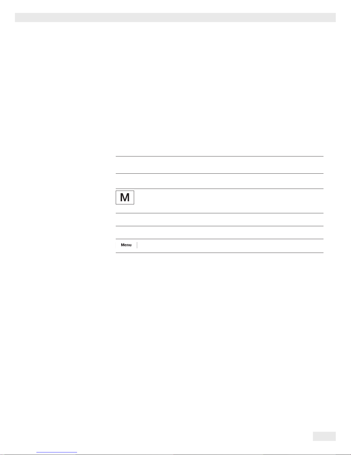
Microbalances: models MSU6.6S, MSU3.6P, MSU2.7S
Item Description
1 Weighing pan
2 Filter weighing pan d 50 mm
3 Internal draft shield (for MSU2.7S-F only)
4 Optional weighing pan d 75 mm
5 Shield disk
6 Optional weighing pan d 90 mm
7 Shield plate
8 Level indicator
9 Leveling foot
10 MSA2.7..model: socket
11 Draft shield cover
Item Description
12 Female connector for weigh cell
13 DC jack
14 Display and control unit
15 Serial communications port (PERIPHERALS)
16 Slot for optional interfaces
(e.g., 9-pin data output and PS2 or Bluetooth)
17 Lug for attaching antitheft locking device
18 Weigh cell connector - electronics module
19 Equipotential bonding conductor terminal
20 Draft shield
Not shown: AC adapter, USB cable
Use6
9719
87
1
2
3
4
5
6
7
8
9
10
11
12
13
14
15
16
17
18
7
1
3
19
Page 7
Cubis® MSU User Manual 7
General View of the Equipment and Equipment Supplied
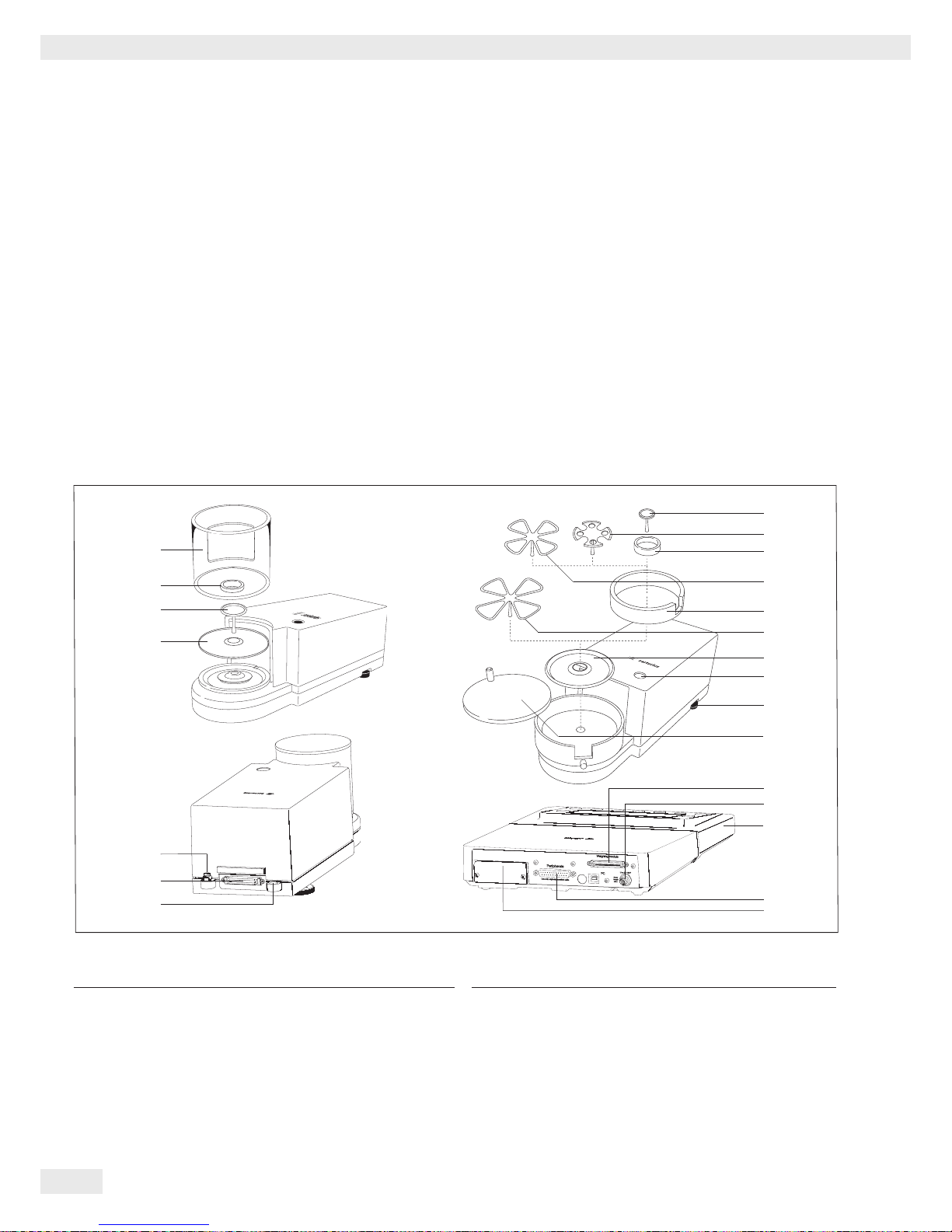
Models MSU66S, MSU66P, MSU36S, MSU36P
Item Description
1 Push handle/Handle
2 Inner draft shield
3 Weighing pan
4 Shield disc
5 Level indicator
6 Leveling foot
7 SD card slot
8 USB interface for PC connection
9 Weigh cell female connector
Item Description
10 DC jack
11 Display and control unit
12 Serial communications port (PERIPHERALS)
13 Slot for optional interface
(e. g. 9-pin data output and PS2 or Bluetooth)
14 Connection plug: Weigh cell – electronics module
15 Equipotential bonding conductor
16 Lug for attaching anti-theft locking device
Not shown: AC adapter, USB cable
1
16
15
6
14
Use6971
9
87
7
8
9
10
11
12
13
1
2
3
4
5
6
Page 8
8 Cubis® MSU User Manual
General View of the Equipment and Equipment Supplied
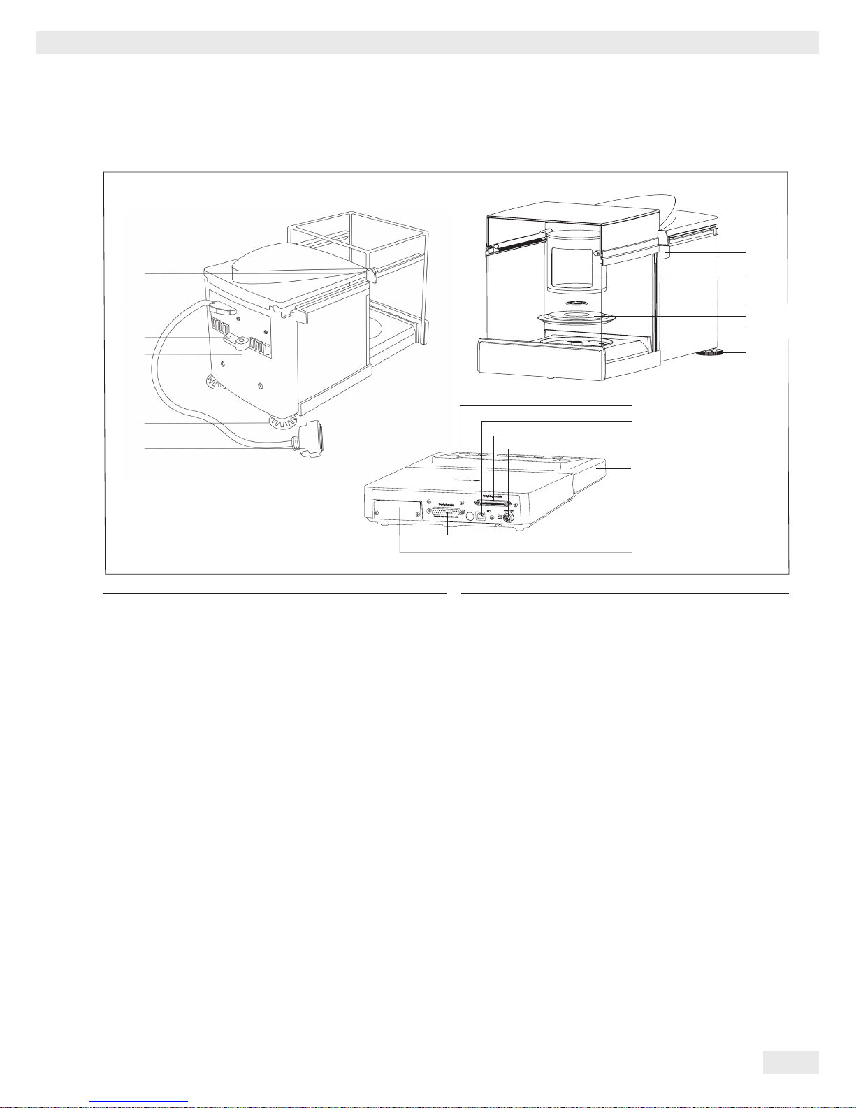
Model MSU116P
Item Description
1 Push handle/Handle
2 Inner draft shield
3 Weighing pan
4 Shield disc
5 Level indicator
6 Leveling foot
7 SD card slot
8 USB interface for PC connection
9 Weigh cell female connector
Item Description
10 DC jack
11 Display and control unit
12 Serial communications port (PERIPHERALS)
13 Slot for optional interface
(e. g. 9-pin data output and PS2 or Bluetooth)
14 Connection plug: Weigh cell – electronics module
15 Equipotential bonding conductor
16 Lug for attaching anti-theft locking device
Not shown: AC adapter, USB cable
1
16
15
6
14
U
se69719
87
7
8
9
10
11
12
13
1
2
3
4
5
6
Page 9

Cubis® MSU User Manual 9
General View of the Equipment and Equipment Supplied
General View of the Equipment
and Equipment Supplied
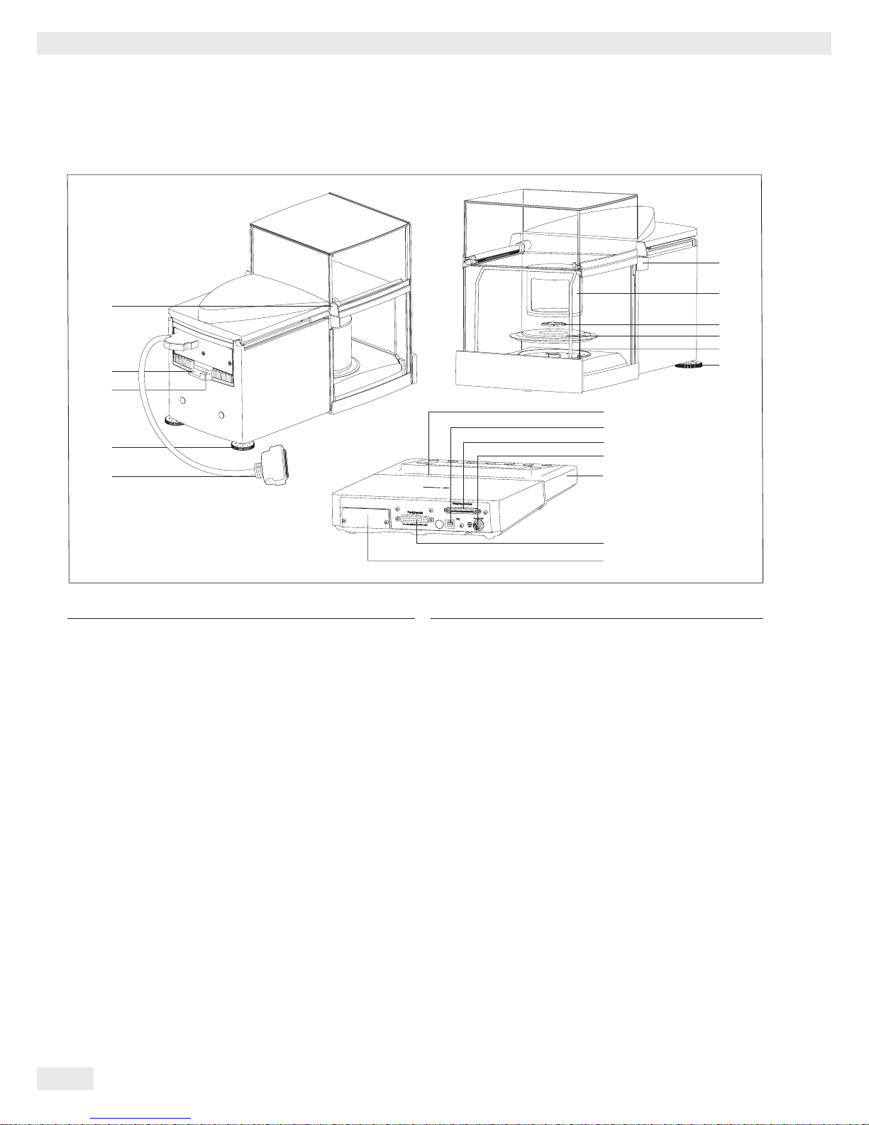
Analytical and precision balances with a weighing range of up to 15 kg
Item Description
1 Upper sliding draft shield panel/handle
2 Back panel
3 Weighing pan
4 Pan support (not for MSU225.../MSU125... models)
5 Shield plate
6 Pan retainer
7 Right sliding panel/handle
8 SD card slot
9 Leveling foot
10 Display
11 Display and control unit
12 Draft shield/Shield disk (only for models
with a readability of 1 mg and 10 mg)
13 Below-balance weighing port
(on the bottom of the balance)
14 Leveling foot
15 Level indicator
16 Power socket
17 Slot for attaching an anti-theft device
18 USB socket for a PC connection
19 Below-balance weighing hook
20 Slot for optional interfaces,
e.g., 9-pin data output and PS2 (as shown) or Bluetooth
21 Communication port (PERIPHERALS) for accessories
22 Menu access switch
23 Left sliding panel/handle
24 Ethernet interface
(on the bottom of the display and control unit)
25 Semi-microbalances: Female connector for weigh cell
26 Semi-microbalances: Electronics module
(for MSU225.../MSU125... models)
Not shown:
– AC adapter
– USB cable
– Operating instructions
10
11
23
3
4
5
5
6
6
13
13
11
11
14
14
6
12
12
4
3
3
15
16
17
18
19
20
21
22
4
25
26
15
17
20
21
22
1
2
3
4
5
6
7
9
8
24
Page 10

10 Cubis® MSU User Manual
General View of the Equipment and Equipment Supplied
General View of the Equipment and Equipment Supplied
Balances with a weighing range of 20 kg or more
1
3
4
5
7
2
6
Item Description
1 DC jack
2 Leveling foot
3 Level indicator
4 Serial communications port (PERIPHERALS)
Item Description
5 USB socket for a PC connection
6 Display and control unit
7 Weighing pan
Not shown: AC adapter, USB cable
Page 11
Cubis® MSU User Manual 11
Getting Started
Getting Started
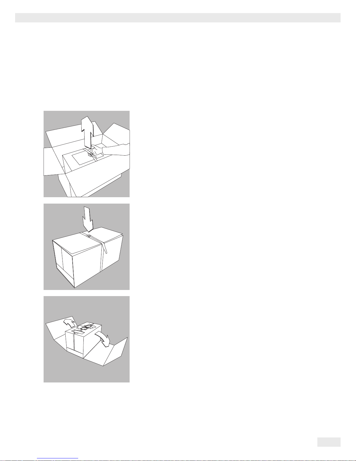
Unpacking
Models MSU116P, MSU66S, MSU66P, MSU36S, MSU36P:
t Lift the package containing the device out of the outer packaging by the strap.
t Loosen and remove the strap.
t Remove the cardboard sleeve.
Page 12
12 Cubis® MSU User Manual
Getting Started
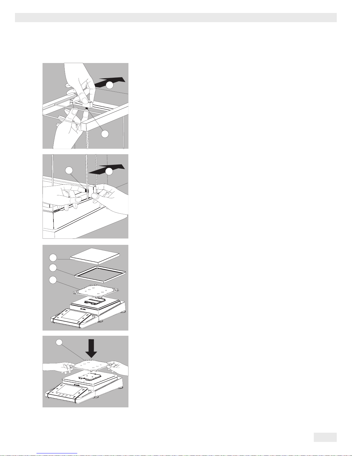
t Remove the following parts from the recessed spaces of the inner packaging:
− Weighing pan
− Shield plate
t Remove the lateral packaging paddings of the inner packaging by pulling out-
ward.
t Remove the retainer securing the front draft shield panel.
t Open the plastic wrapping.
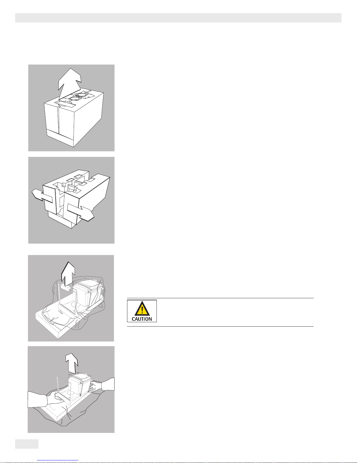
Exercise caution to avoid glass breakage.
Never lift the device by the draft shield panels to remove
it from the packaging.
t Place one hand under the front panel and the other under the back of the
housing and lift the device out of the lower packaging padding.
Page 13

Cubis® MSU User Manual 13
Getting Started
Do not lift the device by the draft shield or the front panel since
this can result in damage.
t Place the device at the intended installation location.
t Open the draft shield doors.
t Remove the inner foam padding from the draft shield.
Save the box and all parts of the packaging in case it should
become necessary to transport the device. Only the original
packaging provides the best protection for shipment (see also
Shipping on page 36).
Before packing the device for shipping, unplug all connected
cables to prevent unnecessary damage.
Balance with the Analytical Draft Shield
t Open the packaging at the top.
t With both hands in the side impressions lift the balance, with the packaging,
out of the cardboard box.
Page 14

14 Cubis® MSU User Manual
Getting Started
t Place the packaging with the balance on the floor.
t Remove the top part of the packaging.
t Remove the packages (containing draft shield panels, weighing pan, pan sup-
port, AC adapter, etc.) from the lower packaging and place them to one side.
3
Caution! Exercise caution to avoid glass breakage.
Never lift the device by the draft shield panels to remove it from the
packaging.
t Use both hands to lift the balance out of the packaging.
t Place the balance on an even surface.
Balance with No Draft Shield
t Use both hands to remove the model without a draft shield from the packag-
ing.
t Remove the AC adapter and the balance parts from the packaging.
Page 15
Cubis® MSU User Manual 15
Getting Started
Assembly
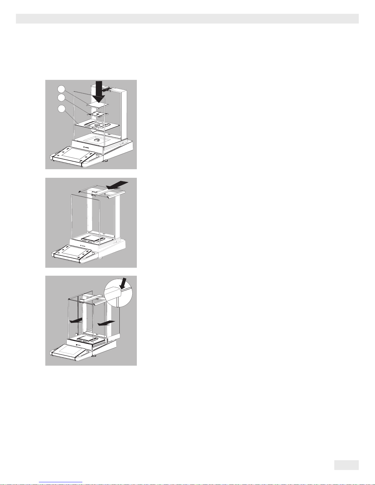
Installing the Analytical Draft Shield Labeled DA, DI, and DU
t Carefully fit parts onto the balance as shown in the picture.
1. Shield plate
2. Pan support (not for MSU225.../MSU125... models)
3. Weighing pan
t Slide the upper draft shield panel into the guide rails from the rear.
t Slide the left and right draft shield panels into the guide rails from the rear.
Make sure the panels are within the upper and lower guide rails.
t Slide the panels in until they engage.
1. Right draft shield panel
2. Left draft shield panel
y This completes the balance assembly.
2
1
3
Page 16
16 Cubis® MSU User Manual
Getting Started
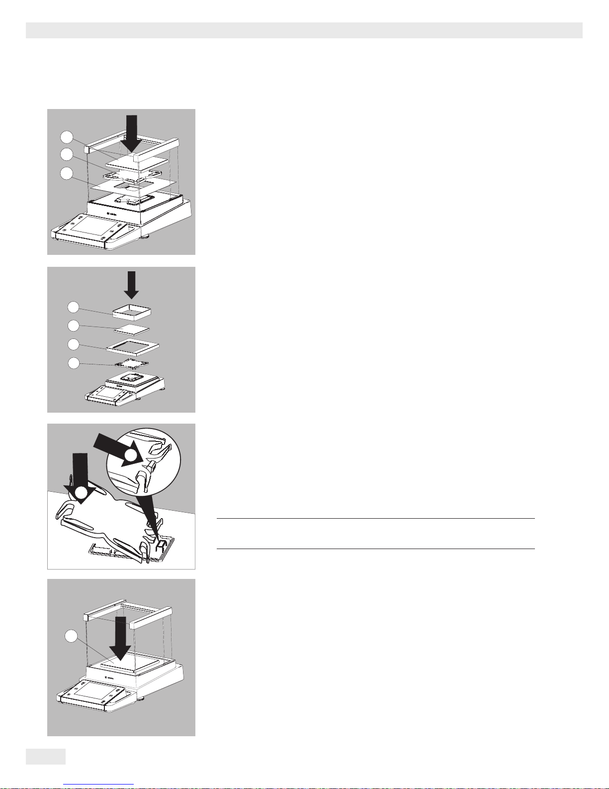
Installing the Draft Shield Labeled DE for Milligram Balances
t Carefully fit all parts as shown.
1. Shield plate
2. Pan support
3. Weighing pan
Assembly of Milligram Balances without Glass Draft Shield (DR Option)
t Fit all components listed below onto the balance in the order given:
1. Pan support (see also next section)
2. Shield plate
3. Weighing pan
4. Draft shield frame
t First insert the shield plate.
t Make sure the pin on the pan support is facing toward the front, and slide it
under the clip on the pan retainer.
1. Insert the pan support.
t After inserting the pan support, press it down against the shield plate so that it
lies flat.
3
Exercise caution to avoid pinching or crushing fingers.
2. Press down on the pan support
t Place the weighing pan (3) on the pan support.
2
1
3
1
2
3
4
3
2
1
3
1
2
3
4
2
1
3
Page 17
Cubis® MSU User Manual 17
Getting Started
t Slide the upper draft shield panel into the guide rails from the rear while
pressing the locking tab.
t Slide the side draft shield panel into the guide rails from the rear while pressing
the locking tab.
y This completes the balance assembly.
t If necessary, remove the panel again:
1. Press on the locking tab
2. Remove the panel
t Place the panel in the storage slot at the back of the balance.
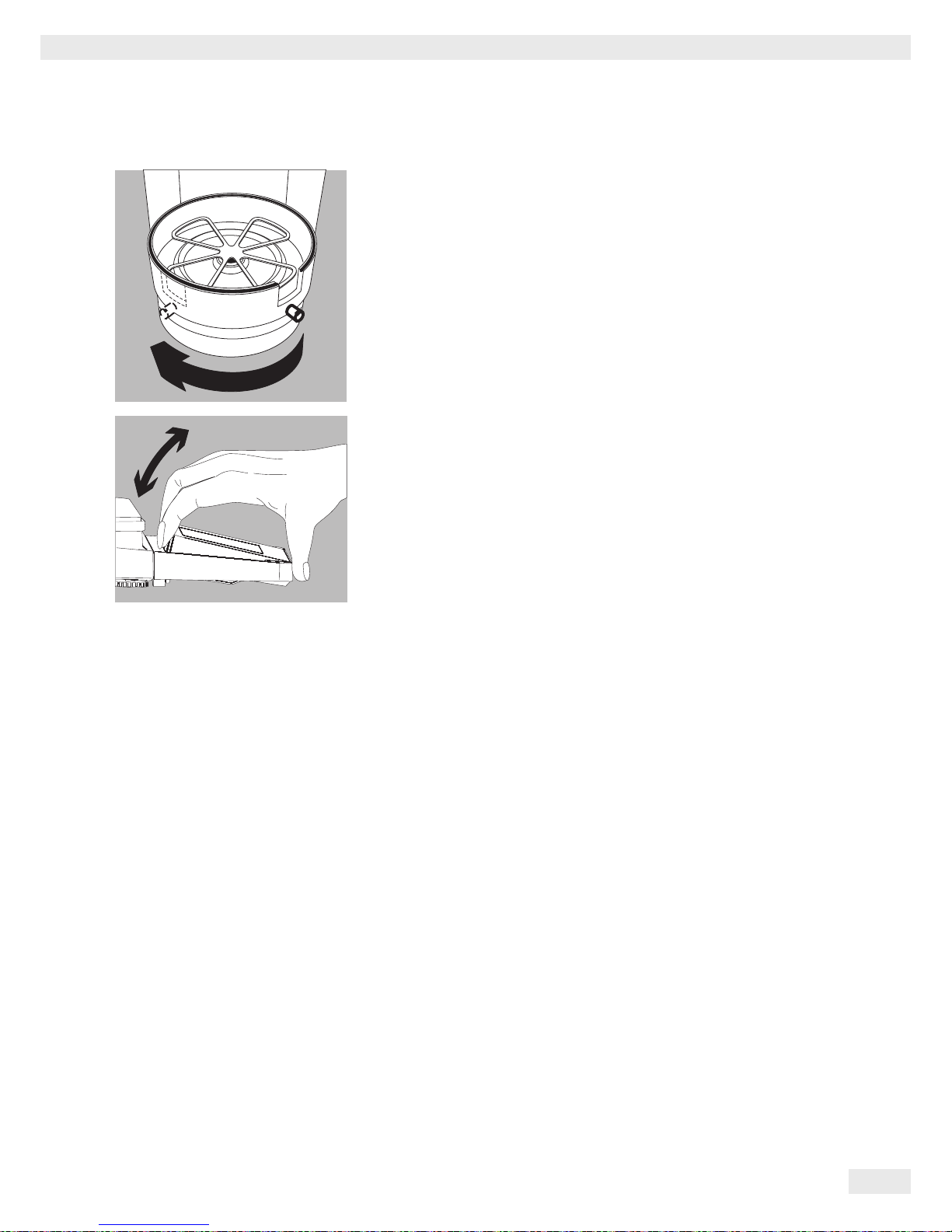
Assembling Precision Balances without a Draft Shield with a Weighing Range of
up to 15 kg
t Carefully insert all parts.
1. Pan support
2. Shield plate/Draft shield
3. Weighing pan
t Place the pan support (1) diagonally and press down lightly.
2
1
2
1
3
1
2
1
Page 18
18 Cubis® MSU User Manual
Getting Started
t Carefully turn the pan support clockwise until the two buttons engage.
The pan support is now attached.
t 2. Insert the shield plate/draft shield.
t 3. Place the weighing pan on the pan support
y This completes the balance assembly.
Balance with the Analytical Draft Shield
t Open the packaging at the top.
t With both hands in the side impressions lift the balance, with the packaging,
out of the cardboard box.
2
3
Page 19
Cubis® MSU User Manual 19
Getting Started
t Place the packaging with the balance on the floor.
t Remove the top part of the packaging.
t Remove the packages (containing draft shield panels, weighing pan, pan sup-
port, AC adapter, etc.) from the lower packaging and place them to one side.
3
Caution! Exercise caution to avoid glass breakage.
Never lift the equipment by the draft shield panels to remove it from the
packaging.
t Use both hands to lift the balance out of the packaging.
t Place the balance on an even surface.
Balance with No Draft Shield
t Use both hands to remove the model without a draft shield from the
packaging.
t Remove the AC adapter and the balance parts from the packaging.
Page 20
20 Cubis® MSU User Manual
Getting Started
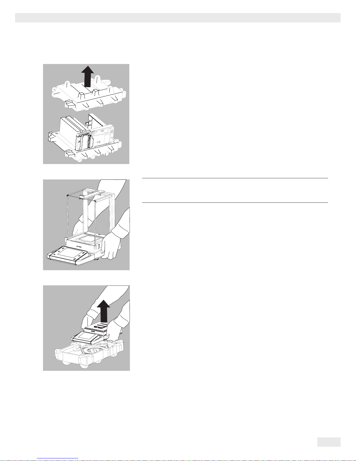
Models with an External Electronics Module: Connecting the Weigh Cell to the
Electronics Module
t Connect the weigh cell and electronics module using the connection cable:
Make sure that the connectors click into place so that both ends engage
correctly.
3
Check the plug contacts to ensure that the connection is correct.
There should be no tension on the connection cable, e.g. if pushed
directly against a wall.
t Connecting the Weigh Cell to the Evaluation Unit:
Make sure that the connector clicks into place so that the cable is engaged.
3
Models with a separate electronics module (e.g. MSU66/36/6.6/3.6/2.7,
MSU225S/P, MSU125P and MSU116P):
Do not mix up the eletronics module.
Interchanging with, e.g. models of the ME/SE series will damage the
device.
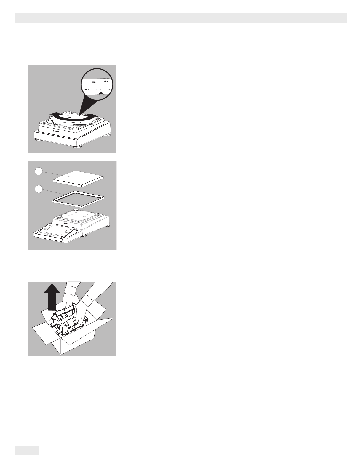
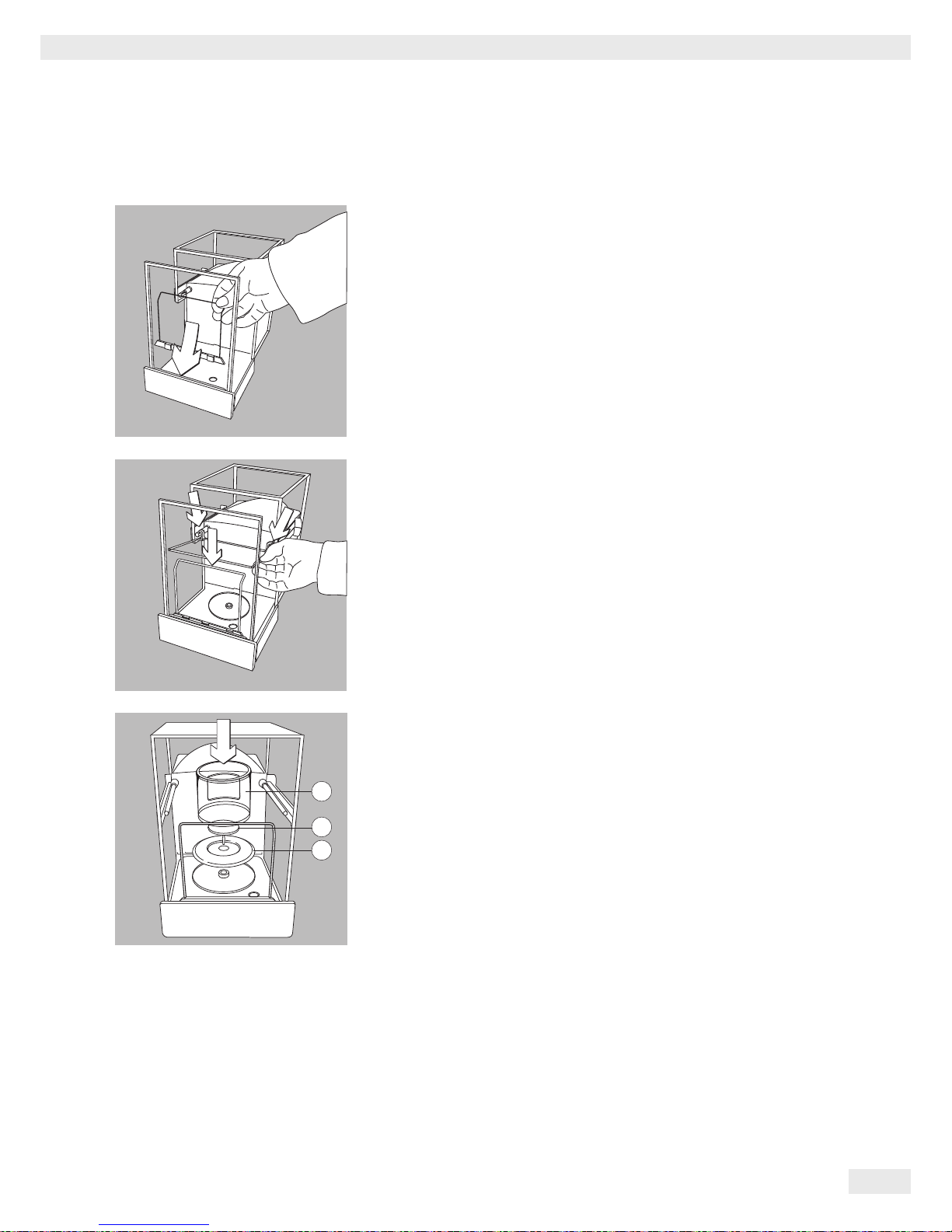
Models MSU66 and MSU36: Placing components into weighing chamber
t Insert the following components into the weighing chamber in the order given:
1. Shield disk
2. Weighing pan
3.
Internal draft shield
1
2
3
Page 21
Cubis® MSU User Manual 21
Getting Started
Model MSU116P: Placing components into the weighing chamber
t Position the support bracket directly behind the front panel.
t Position the glass panel in the retainers and place it at the back of the draft
shield.
t Place the components listed below inside the weighing chamber in the order
given:
1. Shield plate
2. Weighing
pan
3. Internal draft shield
1
2
3
Page 22

22 Cubis® MSU User Manual
Getting Started
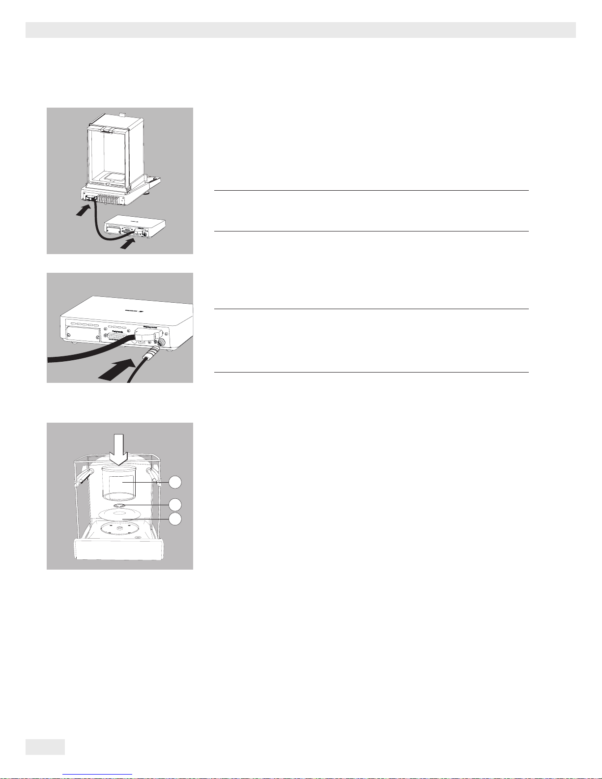
Models MSU6.6S/3.6P/2.7S: Placing Components on the Weigh Cell
t Place the following Parts in the order listed:
t 1. Shield plate
t 2. Shield plate
t 3. Weighing pan
Tip:
After inserting the weighing pan, turn it slightly to the left and right
while pressing it down lightly.
t 4. Internal draft shield (for SE2 only)
t 5. Draft shield: Center the hole over the pan (see arrows).
Filter Balances (models MSU6.6S-F/2.7S-F): Placing Components on the
Weigh Cell
t Place the components on the weigh cell in the order given:
t 1. Model MSU2.7S-F: Connector
t 2. Shield plate
t 3. Internal draft shield
t 4. Filter weighing pan d 50 mm or weighing pan
(optional filter weighing pan d 75 mm or d 90 mm)
Note: After inserting the pan, turn it slightly to the left and right,
while pressing it down lightly.
t 5. Draft shield cover
! Notice
Turn the balance off and then on again after replacing the pan during
operation.
Setting up a filter weighing pan for left-handed users:
t Remove the draft shield cover
t Unscrew the pin and move from the right to the left side
3
2
4
5
1
MSU6.6S/3.6P/2.7S:
MSU6.6S-F/2.7S-F:
Page 23
Cubis® MSU User Manual 23
Getting Started
t Turn draft shield parts approx. 90 degrees to the left (loosen knurled screw).
Setting the Angle for the Display and Control Unit
The angle of the display unit can be adjusted by the user in order to ensure optimal
readability of the weight values on the display at all times.
t The display and control unit can be tilted as desired.
Choosing a Location
t Selecting the right setup location:
– Set up the device on a stable, even surface that is not exposed to vibrations
(e.g., weighing stone).
– Place the device in a location with enough free space around it so that
excessive heat cannot build up.
– Maintain free access to the device at all times.
– The balance may only be used in closed spaces and at a max. height above
sea level (see, chapter Techn. Data, “Ambient conditions”).
Choose a location that is not subject to the following negative influences:
– Heat (heater or direct sunlight)
– Drafts from open windows, AC systems, and doors
– Extreme vibrations during measurement
– Extreme humidity
For further information, please refer to the “Proper handling of analytical balances
and microbalances” document.
Page 24

24 Cubis® MSU User Manual
Getting Started
Acclimatization
Condensation from humidity can form on the surfaces of a cold device when it is
brought into a substantially warmer area.
Allow the device to acclimatize for about two hours at room temperature, leaving it
unplugged from the power supply.
Carefully read all warnings and safety precautions in the respective section of this
manual.
Power Connection
t Check the voltage rating and plug design.
– Make sure that the voltage rating printed on the manufacturer’s ID label is
identical to that of your local mains voltage.
– If the stated supply voltage or the plug design of the power cord does not
comply with your country’s standard, please inform the nearest Sartorius
representative or your dealer.
– The power must be connected in accordance with the regulations applicable in
your country.
– In order to connect the equipment to the power supply (protection class 1),
use a suitable, correctly installed wall outlet with a protective grounding
conductor (PE) and a fuse of a maximum of 16A.
– Only use original Sartorius AC adapters.
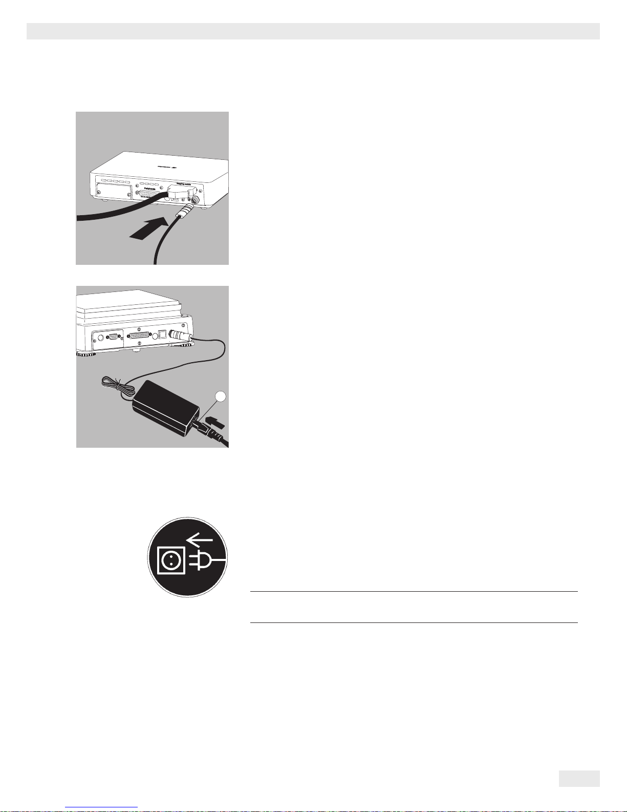
Analytical and precision balances:
1. Plug the DC supply cable of the AC adapter into the power socket of the
balance and tighten the threaded fitting.
°C
1
Page 25
Cubis® MSU User Manual 25
Getting Started
Balances with a readability of ) 0.01 mg
1. Plug the DC supply cable of the AC adapter into the power socket of the
electronics module and tighten the threaded fitting.
2. Plug the power cord into the AC adapter.
3. Insert the AC adapter plug into the wall outlet.
y The balance is now ready to use.
Safety Precautions
The output line of the adapter has a terminal (GND) connected to the metal
housing of the balance. The data port is also galvanically linked to the balance
housing (GND).
Connecting Electronic Devices (Peripherals)
t Make absolutely sure that the device is unplugged from the power supply
before connecting/disconnecting any peripheral device (printer, scanner, PC)
to or from the data port.
3
A device connected to the power supply should never be opened.
2
Page 26
26 Cubis® MSU User Manual
Getting Started
Anti-Theft Locking Device (Accessory)
Balances with a readability of ) 0.01 mg:
t An anti-theft locking device can be installed to the back of the balance if
required.
Balances with a readability of ) 1 μg:
To fasten the anti-theft locking device, use the lug located on the back of the
weigh cell.
Leveling
h
Leveling the balance compensates for slant or unevenness at the
place of installation. The scale must be perfectly horizontal to ensure
consistent, reproducible weighing results. All models are equipped with
an electronic tilt angle detection feature. If the balance is not level, a
warning message appears on the display.
Push-button automatic leveling is available on models with motorized
leveling feet. For models with manual leveling feet, please follow the
instructions on the display.
Leveling the Balance Manually
y The scale is leveled using both front leveling feet.
t Screw in both back leveling feet (only for models with back leveling feet).
t Turn the front leveling feet as shown in the illustration until the air bubble is
centered within the circle of the level indicator.
y Normally, several leveling steps are required
t Turn both back leveling feet until they touch the setup surface (only for models
with back leveling feet).
R
L
L
L
R
R
Page 27
Cubis® MSU User Manual 27
Getting Started
Switching On
t Turn on the device via the A key. The following appears on the display:
y You can now follow the brief instructions to configure further necessary
balance settings before beginning weighing operations.
Warm-up Time
y To deliver precise results as per the Specifications, the balance must warm up
for at least 30 minutes after initial connection to the power supply. Only then
will the device have reached the required operating temperature.
When a verified balance used in legal metrology (legal-for-trade
applications) is connected to the power, it must warm up for at least
two hours before operation.
12
6
93
2
Page 28
28 Cubis® MSU User Manual
Getting Started
Modifying the Balance
Setting Up the Display and Control Unit at the Place of Use
The display and control unit can be removed for all models to enable the operator
to customize the work space.
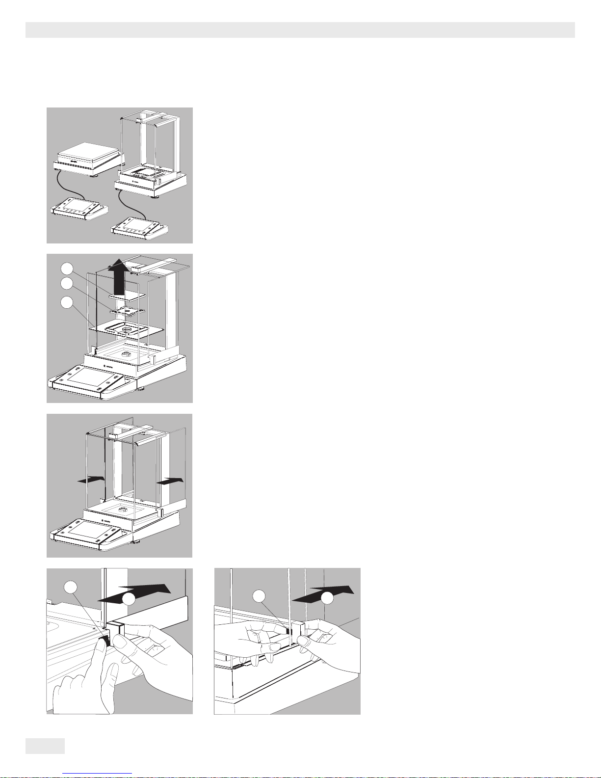
Removing the Retainer with the Display and Control Unit
Analytical balances:
t Remove all items (such as weights) from the draft shield.
t Carefully remove all parts as shown in the illustration.
1. Weighing pan
2. Pan support (not for models MSU225.../MSU125...)
3. Shield plate/Draft shield
t Keep all parts in a safe place.
t Remove the panels (right and left).
Models with the analytical draft shield:
1. Press on the locking tab
2. Remove the panel
Models with the milligram draft shield:
1. Press on the locking tab
2. Remove the panel
t Keep all parts in a safe place.
2
1
3
2
1
2
1
Page 29
Cubis® MSU User Manual 29
Getting Started
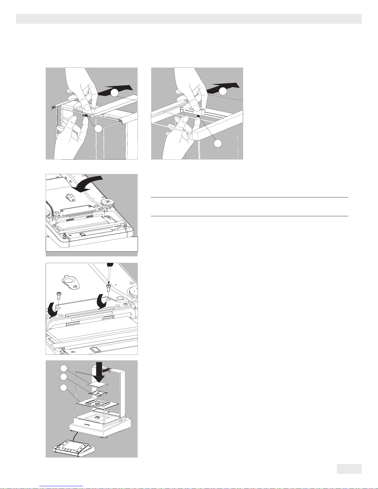
t Remove the upper draft shield
panel.
Models with the analytical draft shield
(left illustration):
1. Press on the locking tab
2. Remove the panel
Models with the milligram draft shield
(right figure):
1. Press on the locking tab
2. Remove the panel
t Keep all parts in a safe place.
t Turn over the balance and place on a soft surface.
3
Exercise caution to avoid breaking the glass on models with a draft shield.
t Use a 2.5 mm Allen wrench to remove the two screws from the display and
control unit retainer bracket.
t Remove the display and re-insert both screws back into their holes.
t Lengthen the cable and position the display and control unit as desired.
t Turn the balance over and place it on an even surface.
t Carefully place all parts on the balance.
1. Shield plate/Draft shield
2. Pan support (not for models MSU225.../MSU125...)
3. Weighing pan
2
1
2
1
2
1
3
Page 30
30 Cubis® MSU User Manual
Getting Started
t Replace the upper and side shield panels.
1. Upper draft shield panel
2. Right draft shield panel
3. Left draft shield panel
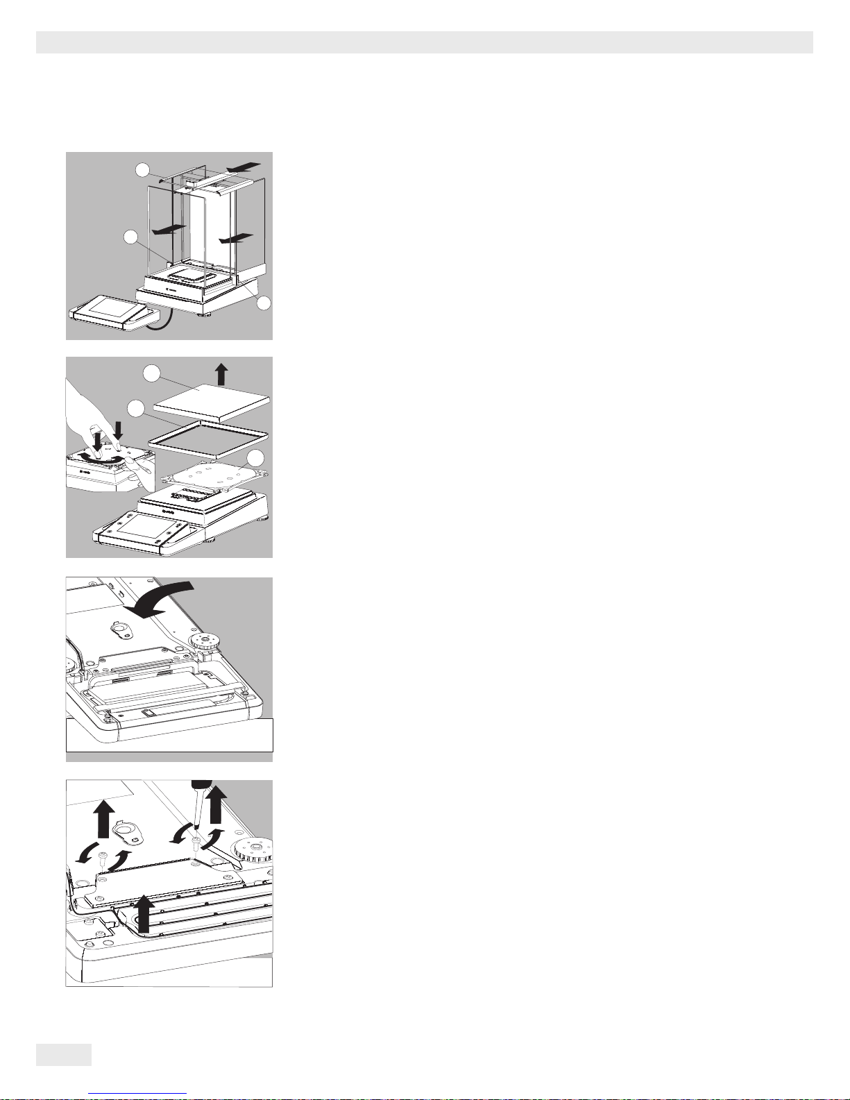
Removing the Display and Control Unit from Precision Balances without a Draft
Shield with a Weighing Range of up to 15 kg
t Carefully remove all parts as shown in the illustration.
1. Weighing pan
2. Shield plate/Draft shield
3. Pan support
t Keep all parts in a safe place.
t Turn over the balance and place it on a soft surface.
t Remove the two retaining screws.
t Remove the display and re-insert both screws back into their holes.
t Carefully pull the cable connected between the display and control unit from
the retainer.
3
2
1
2
1
3
Page 31

Cubis® MSU User Manual 31
Getting Started
t Determine the required cable length.
t Return the balance to an upright position and fit the parts onto the balance.
1. Attach the pan support
2. Shield disk (only for models with a readability of 10 mg)
3. Weighing pan
t Level the balance.
Removing the Display and Control Unit from Models with a Weighing Range of
20 kg or more
3
Remove the weighing pan before unscrewing the control unit, so that
the weighing pan does not fall and cause injury.
t Turn over the balance so that the pan side is facing down.
t Remove the two fixing screws using a screwdriver.
t Remove the control unit and re-insert both screws into their holes.
t Carefully remove the connection cable from its holder.
y
Longer connection cables should only be installed by a Sartorius technician.
2
1
3
Page 32

32 Cubis® MSU User Manual
Getting Started
Semi-microbalances: Attaching the Display and Control Unit to the Electronics
Module (MSU225..., MSU125... models)
The display and control unit can also be attached to the electronics module if
required for operation.
t Turn over the balance and place it on a soft surface.
Remove the connection cable from the cable channel:
t Remove two screws from beneath the weigh cell and detach the plate.
t Remove the connection cable plug.
t Then reattach the plate to the slot.
t Remove the display and control unit from the weigh cell:
Remove two retaining screws.
t Remove the display and control unit.
Page 33

Cubis® MSU User Manual 33
Getting Started
t Attach the display and control unit to the electronics module:
Reattach the two retaining screws.
Open the slot for the connection cable on the electronics module:
t Remove the screws from beneath the electronics module and detach the plate.
Connect the display and control unit to the electronics module:
t Plug in the connection cable.
t Then reattach the plate to the slot.
t Slide the cable that sticks out into the cable channel.
Preparing Below-balance Weighing
A port for a below-balance weighing hook is located on the bottom of the balance.
The below-balance weighing port may not be opened or used on
balances used for legal metrology.
Page 34

34 Cubis® MSU User Manual
Getting Started
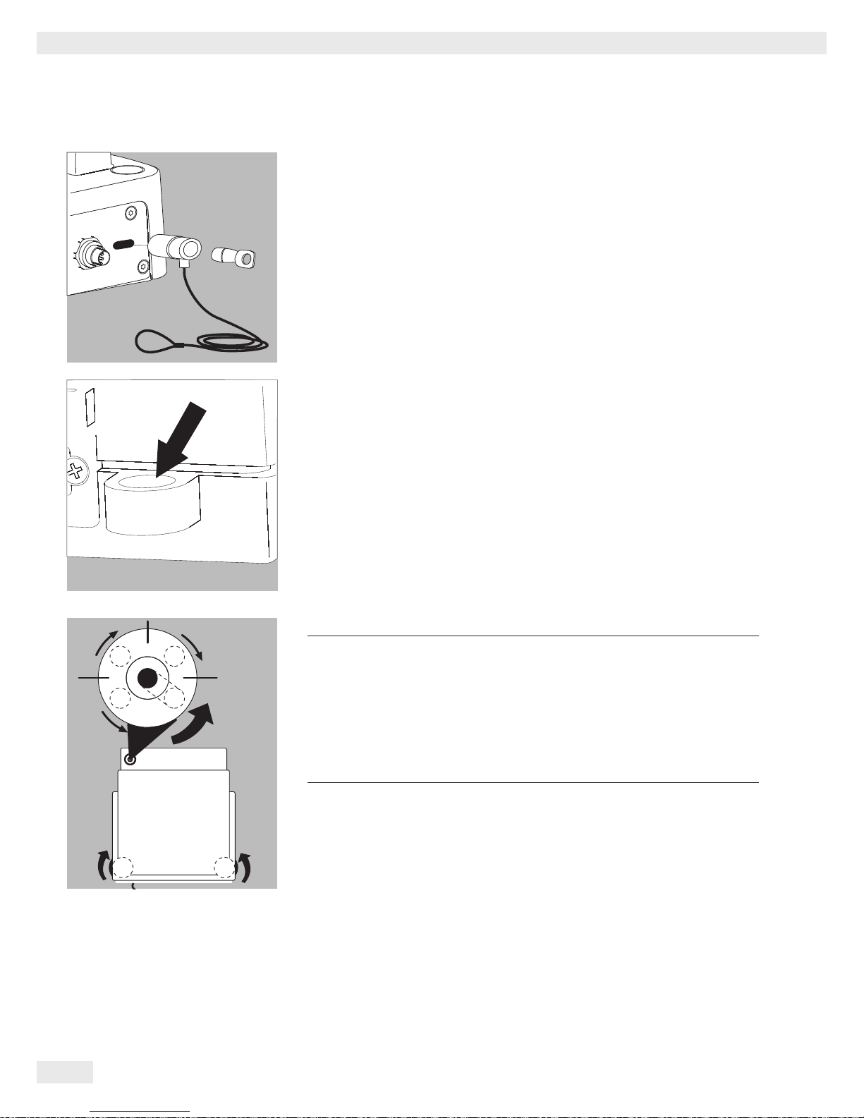
Models MSU116P, MSU66S, MSU66P, MSU36S, MSU36P:
t Unscrew cover plate 3 from the bottom of the comparator
t Hang the container with the sample on the notched hook
t Install a draft shield if necessary
t Lift up weighing pan 1
t Unscrew hook 2
t Insert opposite end of hook 2 into port and refasten
t Place weighing pan 1 back on the device
Models MSU6.6S, MSU3.6P, MSU2.7S:
t Remove both screws from beneath the weigh cell and detach the cover plate.
t For example, attach a wire to sample and hang it on the notched hook.
h
Install a draft protection shield.
Analytical and Precision Balances with a Weighing Range of up to 15 kg:
1. Remove the hook for below-balance weighing from the bottom of the balance.
1
Page 35

Cubis® MSU User Manual 35
Getting Started
2. Push the cover of the below-balance weighing port to one side.
3. Carefully screw on the hook for below-balance weighing.
3
Do not screw it in too tightly,
as this could damage the thread or the balance.
h
Install a draft protection shield.
t Attach the sample (e.g., using a suspension wire) to the hook.
4.
When the below-balance weighing has been completed, unscrew the hook and
return it to the clip under the balance.
Balances with a Weighing Range of 20 kg or more:
t Use a suitable screwdriver to unscrew the cover plate from the bottom of the
mass comparator.
t Request the hook directly from Sartorius.
h
Install a draft protection shield.
Uninstalling Below-balance Weighing Equipment
t After uninstalling the below-balance weighing equipment, you must close the
opening again with the cover.
2
3
Page 36

36 Cubis® MSU User Manual
Getting Started
Using the Cable Opening of the Draft Shield
Models with an analytical draft shield have an opening for passing a cable
(for example, for a temperature sensor) through to the interior of the weighing
chamber.
1. Lift the locking tab on the rear panel of the analytical draft shield.
2. Lift the panel out of the draft shield.
t Turn the panel clockwise 180° so that the opening is at the bottom.
t Install the desired sensor.
t Insert the panel in the guide rail.
t Lift the locking tab and gently press the panel into position.
t Press the locking tab down and close it.
t You can now begin weighing.
Page 37

Cubis® MSU User Manual 37
Moving the Balance
Moving the Balance
Transporting the Device over Short Distances
3
Exercise caution to avoid glass breakage.
Never lift and carry the balance by its draft shield.
t Carry as shown in the illustration.
or
t Carry as shown in the illustration.
Storage and Shipping Conditions
–
Permitted storage and shipping temperature: -10 to +60°C
– Unpacked devices can lose their precision if subjected to extreme vibrations.
– Excessive vibrations may compromise the safety of the equipment.
Save the packaging for any future storage or shipment of the balance.
Only the original packaging provides optimum protection for the equipment.
– Follow all warnings and safety precautions.
– Chapter: “Storage and Shipping”
Page 38

38 Cubis® MSU User Manual
Using the Balance
Using the Balance
Turning the Balance On/Off
t Make sure the balance has been installed and put into operation in accordance
with the installation instructions.
A t Press the on/off key A on the control unit.
y The start screen appears briefly on the display, and then the user interface
appears.
h
On subsequent starts, the most recently active user profile and task are opened
(if at least one user profile has been set up).
t If prompted, level the balance (see Section “Leveling the Balance” for details).
A t To switch the balance to standby mode or turn it off, press the A key.
t Close the draft shield (if your model has one).
Operating Design: Q-Guide
Cubis® precision and analytical balances are controlled by application software with
interactive operator guidance. Once you open a menu or select an application, brief
instructions appear on the display to guide you through the menu or application
step-by-step. At each step along the way, the display shows only those options that
are relevant to your process; this helps prevent unnecessary “detours” and enables
you to reach your goal more quickly.
This type of user guidance is mostly intuitive. Although operation of the balance
is also mostly intuitive, this manual includes a section with very detailed, step-bystep instructions where you can learn about all of the available options
(see “Creating User Profiles” in Section “User Management”).
Basic Operational Structure
The most basic functions, weighing and taring, can be carried out as soon
as the balance is switched on. The application software is divided into three general
areas in which individual settings can be configured:
In Task Management (TASK), task profiles with specific applications, weighing settings, and printout settings can be configured.
User Management (USER) lets you set up user profiles with specific configura-
tion settings and user rights. You can also set up password protection to meet your
security requirements. Your balance can also be used without User Management.
Simple Weighing
D TASK
Task Management (from page 67)
Selecting and starting applications
Configured
at factory
Configured
by user
System Settings (from page 45)
Configuring applications
Configuring tasks
Creating user profiles
H USER
User Management (from page 134)
Selecting user profiles
Page 39

Cubis® MSU User Manual 39
Using the Balance
System Settings (MENU) contains all basic settings and parameters which are used
to operate the balance, affect the entire operation of the balance, and can also
be used for creating new tasks.
Wizard
You can choose between two display types in several menus:
The overview lists all parameters with their set options. You can select each individ-
ual option to change its setting.
When you activate the Wizard in the same menu, the program guides you step by
step: The individual parameters with their options are displayed in succession.
Using the Display and Control Unit
Control Keys (Softkeys):
D
TASK key: opens Task Management, in which applications can be selected and
tasks defined. While working in this menu, you can also use the TASK key to cancel
at any time and return to task overview.
H
USER key: opens User Management, in which user profiles can be selected and
user settings defined. While working in this menu, you can also use the USER key
to cancel at any time and return to user overview.
J
TARE keys – left and right: Zero and tare the balance.
If a balance verified for use in legal metrology is unloaded after taring:
A negative gross value marked with a warning symbol appears. To avoid
this: Apply the value of a container, e.g. using the application “Second
tare memory” (see section “Second tare memory (preset tare)”, page 121.
P
PRINT key: used to print the currently displayed measurement results
or a user-specific print-out
A
On/off key: used to turn on/off and switch to standby
-
Softkeys: used to activate the function displayed directly above them
qwe
Cursor softkeys: used for navigation on the display
O
Operating elements for electronic draft shield (optional)
Page 40

40 Cubis® MSU User Manual
Using the Balance
Adjusting the Display and Control Unit
The tilt angle of the display and control unit can be set as desired to enable optimal
readability for changing working conditions. The color and brightness of the display
can also be changed to match the illumination in the room.
(see “User Management” and “System Settings”).
SD Memory Card for Data Exchange
The display and control unit is equipped with a slot for an SD memory card where
you can import and export data (tasks, user profiles). Handling the memory card
is explained in Section Importing/Exporting Data.
Setting the Language
y The default language for the display is English.
t To change the language, select Menu and then Lang.
t Use the cursor softkeys to select the desired language.
y The display changes directly to the selected language.
t If you would like to select a language that was not included with the equip-
ment supplied but was later downloaded from the Cubis® website, you must
first import the language file (see Section “Importing/Exporting Data”).
y To display the downloaded language, select the last option in the language list
(“Reloadable language”) and then select the desired language.
Quick Guide: First Weighing
A t Press the on/off key A to turn on the balance.
t Close the draft shield (if your model has one).
J t Press the tare key J to tare the balance.
y The balance is tared, and the displayed value is zero.
t If required, open the draft shield and carefully place the sample on the weigh-
ing pan (in a suitable container if required).
t Close the draft shield (if your model has one).
t You can read the measured value as soon as the weight value stops changing
and the unit is displayed.
Page 41

Cubis® MSU User Manual 41
Using the Balance
Display
The display varies depending on whether the application software is in operating
mode or a menu is currently open (setup mode).
Display in Operating Mode
1 Function display: Current task (here: step 1 of 2)
2 Metrology line: Left: weighing capacity (max); right: d = readability (resolu-
tion) of the balance
3 Value range with current measurement value (the numeric value is displayed
in black numbers once the weighing system reaches stability; beforehand it is
shown in gray)
4 Status and warning messages (see below)
5 Task area with instructions on how to proceed
6 Functions which are currently available
7 User field: Display of current user, date, and time
8 For _.CE model balances verified for use as legal measuring instruments:
Display of weights that are not weight values, e. g., calculated values
and values < 0
9 Scaled display of measured value (percentage of weighing capacity utilization)
Status and Warning Messages
Tabs with the following messages may be displayed here:
isoCAL: isoCAL is active (extended temperature range)
isoCAL flashes: Calibration required
Level me! flashes: Balance is not level; leveling required
GLP: GLP print is active; header will be printed
[Maintenance] Maintenance: The next scheduled maintenance date has been reached.
SQmin: The entered SQmin value is permanently displayed
SQmin flashes: The weight value is less than the entered SQmin value
U or U* or PA: The selected DKD value (measurement uncertainty)
is currently displayed.
Ion: Ionizer in progress (only if your model has an ionizer)
1
2
3
5
6
7
8
9
4
Verified balances feature the
following additional displays:
In the line for metrological data:
Min Minimum weight
e Verification scale interval
In the value range:
o calculated values
k Values < 0 and other values
pcs Piece count
Page 42

42 Cubis® MSU User Manual
Using the Balance
Display in Setup Mode
1 Interactive area with instructions on how to proceed
2 Orientation line showing your current location
3 Working area with selectable options
4 Toolbar with the available buttons
5 Symbol indicating which menu (TASK, USER, or MENU) is currently open
6 Scroll bar to view entire selection area
Operating the Display Unit
3
Equipment may be damaged by objects with points or sharp edges
(e. g., ballpoint pens).
Use only your fingertips to operate the buttons and softkeys.
q e w The cursor softkeys can be used to navigate to any of the selectable functions
or settings on the display.
w When you reach the desired menu item, press w to confirm your selection.
Alternative selection: When only one out of multiple options is possible, select
the desired option and confirm with w.
Multiple selection: When several options are available, each option will have
a checkbox. To select or deselect an option, highlight it and then press w.
To continue to the next program step, select Next.
If the scroll bar appears on the right edge of the display, there are more options
than are shown on the display. Scroll down with the cursor keys to view all
of the selection options.
1
2
3
4
5
6
Page 43

Cubis® MSU User Manual 43
Using the Balance
Entering Text and Numbers
A keyboard will appear whenever you have to enter text and numbers.
A cursor appears in the entry line above the keyboard.
t Select the character you would like to insert using the cursor softkeys.
t To accept the character, confirm with Add.
y The character will appear in the entry line.
Press the shift softkey to switch the input mode between uppercase letters,
lowercase letters, numbers, and a complete set of special characters.
Press Add to confirm the selected character and add it to the text line.
The backspace key is used to delete the character to the left of the cursor.
The two arrow keys move the cursor one character to the left or right.
Press OK to exit input mode and save your entry.
Press Back to cancel input mode and go back one program step to the previous
screen.
Opening and closing the rotation draft shield (models MSU6.6S/3.6P/2.7S):
Defining the opening width:
t Touch DraftShld.
yThe settings for the opening angle are displayed.
t Check the settings and change as required.
O
Draft shield opens according to the opening angle setting.
Page 44

44 Cubis® MSU User Manual
Using the Balance
Activating/Switching Users
When the balance is in operating mode, the active user profile is displayed
in the user field at the top right of the screen. To activate another user profile,
open the User Management menu.
H t Press the USER key H.
y The user list is displayed. The user profile that is currently active is indicated
by an arrow.
t Select the user profile you would like to activate.
t Confirm your selection with w.
t If password protection is activated, enter your password.
y The program switches back to operating mode, with the selected user profile
activated.
Page 45

Cubis® MSU User Manual 45
System Settings (Menu)
System Settings (Menu)
This menu contains all balance settings relevant to the device. Basic settings can
be made here that immediately affect the device. Changed settings do not affect
previously defined tasks and user profiles.
h
All system settings are applied to all user profiles.
h
As long as a task is active and/or a user has been selected, several basic settings
cannot be changed. In order to change all settings, “Weighing” has to be selected
in operating mode and no user profile may be selected.
Not all functions/settings can be selected on balances used as legal measuring
instruments.
t To open System Settings, select Menu when the balance is in operating mode.
y The list of available system settings is displayed.
t Use the cursor softkeys to select the menu item for the settings you would like
to edit.
System settings are divided into the following menus:
– Level the balance
– Calibration/adjustment data
– Configure timer controlled actions
– Device information
– Device parameters
– Import/export data
– Service
You have already learned how to use the menus. In the following, only configuration options are described and explained.
Page 46

46 Cubis® MSU User Manual
System Settings (Menu)
Leveling the Balance (Q-Level)
It is essential for exact weighing results that the balance is absolutely level.
The front leveling feet can be used to level out small tilts in the floor. Depending
on the model, the balance is equipped with either motorized or manually operated
leveling feet.
An integrated sensor detects the alignment of the balance and triggers a warning
message when leveling is required. You can configure this warning message and the
automatic leveling function (see System Settings > Balance Parameters).
When the isoCAL function is activated, the isoCal trigger is set after manual
leveling. Balances with motorized leveling feet are leveled automatically prior to
each new calibration/adjustment.
3
Note: The scale needs to be re-leveled and then adjusted each time its setup
location is changed.
When “Level me!” appears on the display, you must level the balance.
t Make sure that the weighing pan is empty.
t Select the option Level the balance from the menu.
Balance with Motorized Leveling Feet (Available for all models with a weighing
capacity of >61 g and <6200 g):
t To start the leveling function, select Next.
t Follow the instructions on the display.
Balance with Manually Operated Leveling Feet
t Follow the instructions on the display.
3
After each leveling routine, the balance must be calibrated/adjusted
(see Section “Calibration and Adjustment”).
Page 47

Cubis® MSU User Manual 47
System Settings (Menu)
Configuring Calibration/Adjustment
Settings are divided into the following submenus:
– Define calibration/adjustment functions
– Define external calibration weights
– Set fully autom. adjustment function isoCAL
t Configure the settings for all submenus.
t To save the settings, select Save.
h
Factory settings are marked with an asterisk (*).
Defining Calibration/Adjustment Functions
Cal./adj. key: Function: Block key / *Configure key selection menu / Select
fixed 1-key function
Cal./adj. selection menu: Select which calibration/adjustment functions
are listed when the Cal./adj. key is touched.
Cal./adj. sequence: Options: *Calibrate, then adjust automatically / Calibrate,
then adjust manually
Cal./adj. unit: Options: *Gram / Kilogram / Defined via data record
Defining External Calibration Weights
No. of ext. cal. weights: Enter the number.
Ext. cal. weight n: Enter the data for each calibration weight: weight value
(in grams), ID, certificate, validation
Configuring Fully Automatic Adjustment Function isoCAL
isoCAL: Define the function setting: Off / Show alert levels, manual start /
*On, automatic execution
isoCAL alert level: *isoCAL status field only / Alert message, repeating /
Error message, adjustment required
isoCAL temperature: Enter temperature difference (in Kelvin).
isoCAL interval time: Enter interval time in hours.
Page 48

48 Cubis® MSU User Manual
System Settings (Menu)
Configuring Timer Controlled Actions
You can program the following actions so that they run automatically at preset
times:
– Show message and execute command (see example below)
– Execute command
– Show message (e. g., a prompt as a reminder)
y The available actions are displayed. When you open this menu for the first time,
the list will be empty.
t Select Edit.
t To define a new timer controlled action, select Create.
Later you can also modify, copy, or delete each action here.
Example: You want the “Internal calibration/adjustment” function to run each
morning at 7:00 a.m. In addition, you want a message to be displayed.
t Select the desired action (e. g., “Show message and execute command”).
t Select the command you want to be executed (e. g., “Internal calibration/
adjustment”).
Page 49

Cubis® MSU User Manual 49
System Settings (Menu)
t Enter the text you want to be displayed when the action is being performed
(e. g., “Timer-controlled adjustment”).
t Enter the time when the action should be performed for the first time.
t Define the time interval at which you want the action to be repeated
(e. g., one day for daily occurrence).
t To start the action at the preset time, select Enable action.
Here you can disable the programmed action at any time and re-enable it later with
a new starting time.
y An overview of all settings for the action is displayed.
t Check and correct all settings as required.
t Select Next.
t Enter a name and a description for the action.
t To save the action, select Save.
Page 50

50 Cubis® MSU User Manual
System Settings (Menu)
y The programmed action is displayed in the list of actions.
You can edit them again at any time here.
Displaying Device Information
You can view various information here.
t Select the information that you want to view.
Displaying Basic Information
Here you can find all information about the manufacturer, model, serial number,
host name, and IP address used.
t To view the parameters for SQmin and DKD, select SQminDKD.
t To view the version of the balance, display and control unit, and application
software, select Version.
t To view the weighing ranges and digits (resolution), select Ranges.
Service Information/Hotline
Service contact information is displayed here along with the hotline number
and maintenance contract and interval information.
Calibration/Adjustment Log File
The log file is displayed here with the results of all calibration and adjustment
routines. The older entries are deleted by new entries on a rolling basis.
View Audit Trail
All changes to the menu, user profiles, and task profiles are logged in the audit
trail. These logs will include the following information: user, profile, parameter ID,
parameter, old and new setting. The older entries are deleted by new entries on a
rolling basis. The audit trail can be deactivated via Sartorius Service.
Page 51

Cubis® MSU User Manual 51
System Settings (Menu)
Alibi Memory
The alibi memory contains (stores) weighing results with date, time, and process
number. This takes place every time a print job is requested [e. g., by pressing
Print P]. Tare and input values are also saved. The alibi memory can therefore
be used as a replacement for a log printer.
The data memory has a ring buffer, meaning that the oldest data records can
be overwritten by new ones. The user can define a memory-time dependent
overwrite protection as well a storage period. Standard: 90 days, see Section
“Device Parameters.” The alibi memory can contain approximately 450,000 data
records; storage capacity depends on the size of each data record.
The alibi memory is verifiable. When the balance is calibrated, you must check that
the alibi memory is correctly functioning by saving some values.
If the alibi memory is being used in legal metrology (according to Council Directive
2014/31/EU), the following must be observed:
– Make sure that there is sufficient storage capacity. Responsibility for this lies
with the operator.
– The weighing results should be stored together with a unique ID code (e. g.,
number or date and time). This makes it possible for every weighing operation or weighing result to be easily assigned and verified if necessary. These ID
codes must be indicated on any receipts generated on peripheral devices.
– All the required tare and net values will be saved during data output.
– It must be possible for the contractual partners involved to be able to check
and verify the stored weighing results.
– Any continuously output weighing results that have not previously been stored
and have no identification codes may only be used for applications that are not
used in legal metrology
(e. g., batching, controlling, or similar). It is not permissible to circulate any
results lacking identification codes for applications used in legal metrology.
– Receipts can be prepared by a peripheral device not subject to legal verifica-
tion in accordance with the preamble to Annex I of Directive 2014/31/EU and
Section 7b (3) 2 of the German Verification Act.
These receipts must contain the following information:
– ID code for every weighing result,
– if used in Germany, a note stating that the weighing results can be com-
pared with the legally stored weighing results using their identification
codes.
You must first install and activate the alibi memory in order to use it (see Device
Parameters > Alibi Memory Configuration).
Searching for and Displaying Data in the Alibi Memory
You can search for data using various search criteria and view the storage capacity
of the alibi memory.
Page 52

52 Cubis® MSU User Manual
System Settings (Menu)
Searching for Data Records by Date
t Select the search function.
y An overview appears on the display.
t Limit the search by selecting the year, month, or day.
t Select Next.
y The desired records are displayed.
t Using the Prev. and Next buttons, you can view more data records from the
selected date.
Searching Data Records by Sequential Number (Data Record Number)
t Select the search function.
t Enter the number for the desired data record.
t Select OK.
Page 53

Cubis® MSU User Manual 53
System Settings (Menu)
y The desired data record appears on the display.
Viewing Information on the Alibi Memory and Available Memory Space
All important status information for the alibi memory is shown here. You can view
the percentage of memory space in use and an estimate of how many data records
can still be stored. The exact number depends on the size of each data record.
Page 54

54 Cubis® MSU User Manual
System Settings (Menu)
Device Parameters
Here you can update the software and change the following device settings.
Settings are applied to all user profiles.
– Configure balance parameters
– Configure data output
– Entering the Device ID
– Set date/time
– Configure display and control unit properties
– Touchscreen adjustment
– Ports
– Alibi memory
– Update software
– Software activation codes (e.g. for “Q-Apps” software options)
– Restoring factory settings
– Motorized draft shield (optional)
– Ionizer (optional)
Configuring Balance Parameters
h
Factory settings are marked with an asterisk (*).
General Weighing Settings
Here you can configure the default settings for general weighing functions.
These settings can be changed for a specific task whenever a new task is created.
h
These settings can only be changed when the balance is set to “Weighing”
in operating mode. If General weighing settings cannot be selected, use
the TASK D button to switch to Task Management and select Weighing.
In order to view detailed information about individual settings, select Info.
Adapt filter: The effects of unfavorable weighing conditions such as drafts or
vibration can be filtered out by adapting the balance filter (and thus its measuring
time) to suit ambient conditions. Options: Very stable conditions / *Stable conditions / Unstable conditions / Very unstable conditions
Application filter: Equalizes the load deviations on the display. Options:
*Final readout / Filling mode / Low filtering / Without filtering
Stability range: The stability indicator lights up when the weighing results are
constant within a set range. Options: Maximal accuracy / High accuracy / *Medium
accuracy / Fast / Very fast / Maximal fast
Stability delay: This setting compensates for slowly abating disturbances, such
as turbulence in the weighing chamber of an analytical balance). Options:
*Very short delay / Short delay / Median delay / Long delay
Zero/tare function: Conditions for performing the tare function.
Options: Without stability / *After stability / At stability
Automatic zeroing: When this option is turned on, the balance is tared auto-
matically when a set fraction of scale intervals per second changes from the display
zero point. Options: On / *Off
Basic unit: Weight unit to be used for this task. Options: Any available weight
unit — the default setting is in grams.
Display accuracy: A lower display accuracy results in a faster display.
Options: *All digits on / Last digit off
Zero/tare at power on: Automatic taring when the balance is switched on.
Options: *On / Off
Page 55

Cubis® MSU User Manual 55
System Settings (Menu)
Leveler Configuration (Q-Level)
You can configure the leveling function here.
Leveling Notice
Off, no indication: Leveling prompt is disabled.
Display status: As soon as leveling is required,
Level me! appears and flashes.
Alarm message, leveling required: As soon as leveling is required,
Level me! appears and flashes. If this notice is ignored, an alarm message appears
after five minutes. If this occurs, you can only continue working after the balance
has been leveled.
Automatic Leveling (Balances with Motorized Leveling Feet Only)
Switch off, start with key: Select Start to activate automatic leveling.
Switch on fully automatic: The balance is leveled automatically before every
calibration/adjustment routine.
t To save the settings, select Save.
Power On Mode
t Select the balance’s startup mode for when the balance is switched on or when
the on/off key A is pressed repeatedly.
Options: On/standby or Always on
t To save the settings, select Save.
Power Saving Mode
t Switch the power saving mode of the balance on or off.
Off, no function: Power saving mode is not in use.
Automatic shutoff after 2 minutes: The backlight on the display
and control unit switches off if the device is idle for two minutes.
t To save the settings, select
Save.
Restoring Factory Settings
You can reset all balance settings back to the default delivery status here
(after confirming the reset when prompted).
Page 56

56 Cubis® MSU User Manual
System Settings (Menu)
Configuring Data Output (Print Parameters)
Here you can configure all settings for printing and data output.
Several of these settings depend on the interface configuration
(see Section “Interfaces”).
h
Factory settings are marked with an asterisk (*).
In order to view detailed information about individual settings, select Info.
Printout interface: Options: COM port A, B, C (file/SD memory card), D and
print to file
Protocol: Options: Print / SBI / xBPI / Web services / SICS / Second display.
This setting cannot be changed here; it is defined when configuring the interfaces.
h
The parameters and settings that are displayed here depend on the configured
protocol.
GLP printing: When should ISO/GLP printing be allowed? Options:
*Off / For calibration/adjustment only / Always on.
Taring after printing: Automatic tare after print
command. Options: *Off / On
Print event: What event should trigger printing?
Options: *PRINT key / Starting a task / Initialization of an application / Application
result / Printing of component / Result from an application (evaluation of application) / End of task / Calibration/adjustment result
Print key elements: Which elements should be printed?
h
For further information, please refer to Configuring Printouts in Section
Interfaces.
Entering the Device ID
With these two IDs, you can expand the printer protocol.
t Select the input for both the IDs
t
Enter the desired value (text) for each identifier.
t To save settings, touch Save.
Associated input and output commands for data output:
See the chapter Interfaces: SBI Commands, page 164
Page 57

Cubis® MSU User Manual 57
System Settings (Menu)
Setting Date/Time
The date, time, and display format can be set here.
Under Date format:
t Select how the date is displayed and printed out.
− Standard: Language-dependent display format
− DD/MM/YYYY or DD.MM.YYYY: The date is displayed in the order of day,
month, and then year.
−
MM/DD/YYYY: The date is displayed in the order of month, day, and then year.
− YYYY-MM-DD: The date is displayed in the order of year, month and then day.
Under Time format:
t Select how the time is displayed and printed out.
− Standard: Language-dependent display format
− HH.MM.SS or HH:MM:SS: The time is displayed in 24-hour format.
− HH.MM.SS on: The time is displayed in 12-hour format. The hours before noon
are displayed with AM, and the hours after noon are displayed with PM.
Configuring Display and Control Unit Properties
The following properties of the display and control unit can be changed as neces-
sary: Language, Background color, Brightness, Acoustic signal.
These general properties are applied to all user profiles, are also used when no user
is logged in, and serve as a template when a new user profile is created.
Configuring Ports and Network Settings)
Here you can configure interfaces (serial ports and network) and settings for
the network.
Also settings for:
– Control inputs/outputs
– Print to file
– FTP server settings
A detailed description of the connection options and data interface ports can
be found in Section Interfaces.
Page 58

58 Cubis® MSU User Manual
System Settings (Menu)
Configuring Serial Ports
y The available ports are displayed.
t Select the port you want to configure.
t Configure all settings for this port.
t To save the settings, select Save.
Configuring Network Ports (Ethernet)
For more information on network operation, see “Network Interface” in Section
Interfaces.
t Select operating mode for the network interface.
No function / xBPI (expanded Sartorius communication / SBI (Sartorius standard
protocol) / Printer output / SICS protocol
t Select connection type.
Server or Client connection
t Configure the local TCP port.
t To save the settings, select Save.
Configuring Network (Ethernet)
t Define the settings for network operation.
The Hostname (device name — max. 24 characters) set here can be printed on logs.
The IP address can be entered and set as a default or obtained automatically.
t To save the settings, select Save.
Page 59

Cubis® MSU User Manual 59
System Settings (Menu)
Control Input/Output (e.g., for Remote Switch)
If you have connected a remote switch, for example, via the peripheral or optional
port, you can define its function here.
t Configure the setting for each port.
t Select the connected hardware device or control function.
h
During checkweighing, the control outputs have no function when set to:
– Foot switch YPE01RC
– Control inputs
t Configure the settings for the control inputs and outputs.
Options: Off, no function / TARE key / PRINT key / Cal./Adj. key /
Zeroing / Taring
t To save the settings, select Save.
Page 60

60 Cubis® MSU User Manual
System Settings (Menu)
Configuring “Print to file”
Purpose:
– Transferring a print file in TXT or CSV format to a SD card or FTP server.
– Viewing a print file directly in an Internet Browser.
t Select Off.
t Specify the file format.
Print to CSV file:
In addition to the SBI output (like in the TXT file), three additional columns are also
written to the file: ID, Value and Unit.
The 4 columns are separated by the “;” character. The “+” sign has also been removed
in the third column and the decimal point has been replaced by a decimal comma
(because of Excel).
t To specify the settings for the automatic or manual data transfer, touch Off.
y The data are deleted from the balance after the automatic or manual transfer
so that only the new data are transmitted the next time there is an automatic
transfer.
y Manual transfer:
Touch Trans.SD or Trans.FTP during operation to transfer data to the SD card in
the balance or to the FTP server.
y The transfer takes place in the data/print directory.
t Select the output medium for the file.
y This file can be transferred manually or automatically to the SD card of the FTP
server. Combinations are also possible, e.g. manual transfer to the SD card and
automatic transfer to the FTP server.
“To SD card”:
y When exporting, print files can also be exported to the SD card independent of
the transfer. This will create a copy (backup) of the file to the SD card. This does
not delete the file from the balance. After the export, the files are located in the
directory data/all/EXPORT-xxxx/print.
Page 61

Cubis® MSU User Manual 61
System Settings (Menu)
“To FTP server”:
y If you use the FTP server option for the transfer, the parameters for the FTP server
must be entered in the menu (see next section). The user must have the rights to
create subdirectories on the FTP server.
t Select the desired interval, the date and the time of the first transfer.
t To save settings, touch Save.
Configuring Data Transfer Settings for an FTP Server
t Specify the data transfer settings to a FTP server.
t Enter the following parameters for the FTP server:
IP address, port, FTP user name, FTP password and optionally a subdirectory as
well. The user must have the rights to create directories on the FTP server.
t For more information about displaying a print record via an Internet browser,
go to Interfaces, “Remote Control of the Balance from a PC via Ethernet”
section.
Page 62

62 Cubis® MSU User Manual
System Settings (Menu)
Configuring the Alibi Memory
Here you can switch on the alibi memory, delete the recorded data, and set
the interval for automatic deletion.
t Use the cursor softkeys to navigate through the Device parameters
submenu to Alibi memory configuration.
Alibi Memory On/Off
t Select whether you want to have the alibi memory switched on or off.
Automatic Deletion of Older Data
t Define whether the data stored in the alibi memory should be deleted auto-
matically at regular intervals after a pre-specified time.
t If data should be regularly deleted, enter the desired interval (deletion cycle)
in days.
Reset and Initialize Alibi Memory
You can delete all data from the alibi memory immediately. The settings for the alibi
memory (on/off, deletion cycle) will remain stored.
t To delete data in the alibi memory, confirm deletion when prompted.
Updating the Software
Cubis® software is updated at regular intervals. A detailed description of how
to perform a software update on your balance can be found in Section Updating
the Software.
Restoring Factory Settings
You can reset all settings individually to the factory settings at any time.
t Use the cursor softkeys to navigate through the Device parameters sub-
menu to Restore factory settings.
t Mark any settings you wish to reset and select Next.
t Confirm the reset when prompted.
Page 63

Cubis® MSU User Manual 63
System Settings (Menu)
Motorized Draft Shield (Optional)
O
On balances equipped with a motorized draft shield [sometimes called a windshield
(WS)], the control unit has keys on the right and left sides which can be used for the
motor-driven opening and closing of the draft shield doors. You can configure the
functionality of these keys in the menu.
Models with the analytical draft shield: for example, you can configure the left key
to open and close the right and upper door (for users who are right-handed) and
the right key to open and close the left door (for users who are left-handed). The
opening width (entirely or partially) of the sliding panels can also be defined. You
can configure these settings manually on the draft shield itself (see “Learning Function” below).
t Check and correct all settings as required.
t
To save the settings, select Save.
t Define the functions for the left and right keys:
Off, no function: The keys have no function.
Same function: Both keys have identical functions.
*Separate function: The left and right keys are configured with different
functions.
Page 64

64 Cubis® MSU User Manual
System Settings (Menu)
Models with a rotation draft shield (MSU6.6S/3.6P/2.7S):
Same function
(one open position)
Separate function
(two open positions)
Defining the
opening width
Manually select the
desired opening position
–
Touch the O key
1) Open to the previously
selected opening
position
2) Close
1) Touch the left O key:
Opens 260° clockwise
Right key O:
Opens 100° counter clockwise
2) Close
100°
180°
260°
0°
Page 65

Cubis® MSU User Manual 65
System Settings (Menu)
t Configure the automatic mode for the draft shield.
*Off, no function: Automatic mode is off.
Close -> function -> open: The draft shield doors are closed in automatic mode
while the function is executed, and then the doors re-open.
Close > function: The draft shield doors are closed in automatic mode while
the function is executed.
Automatic mode can be executed using the following keys:
– TARE key
– PRINT key
– Cal./Adj. softkey
– or can be executed
when a component is saved for logging applications
(statistics, formulation, totalization)
h
If automatic mode is on, the draft shield doors automatically close when the
balance is switched to standby.
Assigning Opening Functions to Keys (Learning Function)
The keys should be cross-configured (for example, left key opens and closes right
door and vice versa).
The balance must be turned on.
t Close all draft shield doors.
t Manually operate the door you want to assign to the left key: Push the right
door open to the extent you want it to be opened (entirely or partially).
t Press the left key
O.
y The door will close again. Now you have configured the left key so that,
when pressed, it opens or closes the right door.
t Proceed accordingly to configure the left door/right key.
h
Using the same method, you can assign operation of the upper door to one
of the keys. You can also configure one key to move both doors by manually
opening both doors during setup and then pressing the desired key.
Configuring the Ionizer (Optional)
If your balance is equipped with an ionizer module, you can configure the basic
settings for the ionizer module here. These settings can be changed as necessary
during any electrostatic charge eliminator task.
t Define ionizer function.
Switch off ionizer: The ionizer is switched off.
Manual activation with [Ion] key: Ionization can be turned
on at any time by pressing the Ion key.
*Automatic execution after closing of ws: Ionization is executed
automatically, as soon as the draft shield is closed.
Page 66

66 Cubis® MSU User Manual
System Settings (Menu)
t Define how long an ionization routine should take.
Operating time in seconds: 3 to 15 sec., *8 sec.
t Define the intensity of the ionization.
Soft intensity / *Normal intensity / Strong intensity
t Check and correct all settings as required.
t To save the settings, select Save.
Page 67

Cubis® MSU User Manual 67
Task Management
Task Management
In the Task Management menu (TASK), you can:
– Start a task
– Configure a new task
– Edit an existing task (modify, copy, delete)
For task configuration, there are numerous applications available, e. g., weighing,
parts counting, calculation. Each task contains at least one of these applications.
However, it can also have a combination of several applications. Each application
can be used either with their factory settings, or you can modify them as desired.
The Weighing application is available as a basic function for every task. Each task
also contains the individual balance settings and the individually configured print-
out.
The options available to you in Task Management depend upon your user access
rights: An Administrator can use all options, while a User can only use limited
options (see “User Management”). If no users have been defined, all options can
be accessed. A maximum of 15 tasks can be created.
The administrator can create tasks with restricted use, i.e., tasks that can only
be used by certain users or only by the administrator himself.
Global tasks can be used by all users.
Separate tasks are only accessible to the users who created them.
Exception: A user can copy global tasks to use them afterwards as a separate task.
Option Administrator User
Configure, modify, delete separate tasks i
Configure, modify, delete global tasks i
Execute or copy separate tasks i
Execute or copy global tasks i i
Selecting Tasks
D t To switch to Task Management, press TASK D.
y A list of available tasks is displayed.
Initially, this overview will be empty. Once tasks have been configured, they will
be displayed here.
t When you touch Start, the task currently selected will be started (indicated
by the dark background).
Importing Tasks:
You can also load preconfigured tasks to the balance:
1) Unpack the desired ZIP archive file to the root directory (Root Dir) of a SD card
after downloading from the Sartorius homepage or from the included CD.
2) In the Balance menu, submenu “Import/Export data:
Import files from the SD card.”
3) Insert the SD card into the balance.
4) Select the corresponding import file and active the task download via Next
. Then exit the menu.
5) Start the loaded task via the selection list.
Page 68

68 Cubis® MSU User Manual
Task Management
Using Applications with the Factory Settings
Each application comes with specific factory settings.
If you want to apply these settings unchanged, you can do this quickly during
configuration:
D
t Open Task Management and select Edit.
t Select Create.
y An application list is displayed.
t Select the application you want to assign to the new task.
t Select Done.
t Enter a name and a description for the task and select Save.
y The new task is saved with the factory settings and displayed in the task list.
Sorting the Task List
New tasks are always added to the end of the task list. After you have configured
several tasks, it may be helpful to sort the task list.
D y The task selection is displayed.
t Select Sort.
y The list is sorted alphabetically (A – Z).
t To reverse the sort order, select Sort again.
t To sort tasks by the date of last use, select Sort again.
Creating New Tasks (Configuration)
The Cubis® software contains the following applications that you can configure
as tasks as required:
– Weighing – Weighing in percent
– Mass unit conversion – Timer-controlled functions
– SQmin minimum weighing (optional) – Totalizing
– Individual identifiers – DKD uncertainty of measurement (optional)
– Density determination – Second tare memory (preset tare)
– Statistics – Parts counting
– Calculation – Checkweighing
– Averaging – Draft shield (optional)
– Formulation – Ionizer (optional)
Page 69

Cubis® MSU User Manual 69
Task Management
The basic procedure for configuring a task is:
1. Create new task.
2. Select application.
3. Review all of the following prompts and configure your own settings as
required.
4. Perform steps 2 and 3 for additional applications if you would like to combine
multiple applications.
5. Check settings for weighing and printouts and modify as required.
6. If you are an administrator, define whether the new task can be used by all
or only by certain users.
7. Enter a name and description for the new task.
8. Save task.
Combine applications?
no
yes
Create new task
Select application
Review settings
Settings for weighing
Settings for printing
Enter task name/description
Save task
Page 70

70 Cubis® MSU User Manual
Task Management
Example: Creating a Task
D t Open Task Management and select Edit.
y The list of options is displayed.
t To define a new task, select Create.
y The list of applications is displayed.
t Use the cursor softkeys to view all applications.
t Select the application you want to assign to the new task.
t Configure this application as required. The program guides you through
the configuration menu.
t If you want to assign additional applications to the task, these applications
should also be configured (see “Combining Applications into One Task”).
y After all applications for the new task have been configured, the settings
for weighing and printouts must be configured. All settings configured here
will only affect the new task.
On balances verified for use in legal metrology, the modification of some settings
may be limited or prohibited altogether.
Settings for Weighing
t Check all settings and change as required.
Explanations for the individual options can be found in Device Parameters
in Section System Settings.
t Select Next.
Settings for Printouts
t Check all settings and change as required.
Explanations for the individual options can be found in the following section.
t Select Next.
t Enter a short name and a description for the new task.
t Select Save.
y The task selection list with the new task is displayed.
Page 71

Cubis® MSU User Manual 71
Task Management
Configuring Printouts
You can configure the printout at two places; for example, you can have the printout
for basic weighing differ from all the other applications.
In the System Settings (Menu) You define the basic settings in the menu. Previously created tasks will not be
affected by modifications to the basic settings.
Creating Tasks This is where you can specifically modify the user-defined settings for any task. You
will be routinely prompted for the printer settings with every new task you create
and can then modify them.
Printout (Example): Print events Printout content (record) Print elements
Start task
Start task
e.g. here:
Start task
P key
End task
------------------
21.02.2017 09:17
SARTORIUS
Mod. MSU 224S
Ser. no. 12-34-56
------------------
Laboratory
technician
Product...........
123.5678g
------------------
21.02.2017 09:20
Name:
------------------
GLP header
Operator name
ID1, identification: fixed/variable
Measured values
GLP footer
Settings for Printouts
During printout configuration the following parameters are defined:
Printout interface Peripheral ports (Com A), USB/PC (Com B), optional interface (Com C), Ethernet
(Com D)
Protocol (operating mode) Depends on the interface: Print, SBI, xBPI, SICS
Output Depends on the operating mode: Single printout or automatic print (not with
printer), with/without stability. For “Autom. Print” for the fasted display result,
set additional software handshake or no handshake.
Printout criterion Manual without stability, manual with stability
Format auto. print 22 characters for applications, 16 characters for raw data
Standard data output Standard 1 (measured value only), Standard 2 (measured value and date/time),
Standard 3 [date/time, weight block (N,T,G), and dotted line]
GLP printing Off, no GLP printout / For calibration/adjustment only / Always on
Print event Defines which event should trigger a print job.
The selectable print events depend on the selected application.
For basic weighing: P key, start or end of task, calibration/adjustment result.
For calculating applications: additional initialization and result.
For logging applications: additional component and evaluation
Print elements The elements to be printed also depend on the selected application. Define the
print elements for each each event, e. g., date and time, dotted line, measured
value, and the sequence in which they should be printed, etc.
Tare after printing: Off, no tare / On (automatic tare after print request)
Page 72

72 Cubis® MSU User Manual
Task Management
Configuring Printouts in the System Settings (Menu).
h
The settings can only be modified as long as no task has been activated (ready to
start) in the operating mode. Make sure that basic weighing is active in the operating mode.
t Toggle to the System Settings menu.
t Open the Configure data output submenu.
If the submenu is not selectable, check the operating mode and select basic weighing.
y The setting menu will open. Several options are not modifiable because they
are preset by the interface configuration.
The initial default setting and several examples of settings are described in the
following.
Page 73

Cubis® MSU User Manual 73
Task Management
Standard Printout Parameters When the Balance is First Delivered
When the balance is first delivered, two ports are configured: The peripheral port
(Com A) is configured for one printout; the USB port (Com B) is configured for data
exchange with a PC via SBI protocol.
Printout interface: Com A (peripheral port) and Com B (USB/PC)
Protocol to Com A: Print (preset by the port configuration)
Standard printout to Com A: Standard 1 (measured value only)
GLP printing to Com A: Off, no GLP printout
Print event for output to Com A: Press the PRINT P key
Element to be output via Com A: Measured value
Protocol to Com B: SBI (preset by the port configuration)
SBI output to Com B: Single printout to the PC
Criterion for output to Com B: After stability of balance
Format for output to Com B: 22 characters
Tare after printing: Off, no tare
O t The cursor softkeys can be used to select configurable parameters individually.
or
t To be guided step-by-step through the settings, use the wizard.
Example Manual Printout to Peripheral Port, SBI Operating Mode
y After manual operation, you would like a single printout to be printed by the
connected peripheral device.
Printout interface: Com A (peripheral port)
Protocol: SBI (toggling to port configuration possible)
SBI output: Single printout
Criterion: Manual without stability
Format: 22 characters (for applications)
Tare after printing: On or off
Example Automatic Printout to Peripheral Port, SBI Operating Mode
y At a preset interval, automatic printouts should be sent to the connected
peripheral device.
Interface: Com A (peripheral port)
Protocol: SBI (toggling to port configuration possible)
SBI output: Automatic printout
Criterion: Without stability, at stability, or after weight change
Format: 22 characters (for applications)
Stop automatic printing: Not possible or by pressing Print P key.
Interval for automatic printing: Number of cycles (1, 2, 5, 10 to100) and 0.1, 0.2,
0.5 to 10 seconds
Page 74

74 Cubis® MSU User Manual
Task Management
Example Automatic Printout to Peripheral Port, Second Display Operating Mode
y At a preset interval, automatic printouts should be sent to the connected
peripheral device as a second display.
Printout interface: Com A (peripheral port)
Protocol: Remote display (toggling to port configuration possible)
SBI output: Automatic printout
Criterion: Without stability, at stability, or after weight change
Format: 22 characters (for applications)
Interval for automatic printing: Display updates (1, 2, 5, 10 to100) or every 0.1, 0.2,
0.5 to 10 seconds
Example Printout to Peripheral Port Only By Pressing the PRINT P Key; Printer
Operating Mode
y After pressing the Print key, the measured value should be printed by the
connected peripheral device.
Printout interface: Com A (peripheral port)
Protocol: Print (toggling to port configuration possible)
Standard printout: Standard 1 (measured value only), Standard 2 (measured value
and date/time), Standard 3 (measured value with date/time and weight block)
GLP printing: On or off
Print event: Press the PRINT key
Elements for print event PRINT: Measured value PRINT.MEASURE
Tare after printing: On or off
Printout Parameter Settings
Standard Printout
You can select which data should be printed out as default.
Standard 1 (measured value only)
Standard 2 (measured value and date/time)
Standard 3 (measured value with date/time and weight block)
User input is only selectable if the default settings have been modified
by the user.
GLP Printing
You can select if and when the printout should be GLP-compliant.
Off, no GLP printout
For calibration/adjustment only
Always on
User input
is only selectable as long as none of the three options apply, i.e.,
if only a GLP header but not a GLP footer has been configured.
Page 75

Cubis® MSU User Manual 75
Task Management
Print Events
You can define one or several events that trigger a printout.
The number of selectable print events depends on the selected application.
Basic Weighing:
PRINT key
Starting a task
End of task
Calibration/adjustment result
, after calibration/adjustment
For calculating applications the following events are also possible:
Initialization of an application
Application result
For logging applications the following events are also available:
Component
Evaluation
The application-specific print events cannot only be configured when a new task
is created and not in the basic menu.
Print Elements
Which information should be printed?
Measured value
GLP header
GLP footer
Space line
Dash line
Form feed
Date and time
etc.
O t The cursor softkeys can be used to select elements individually.
t To view the complete list, select EXTEND.
t To minimize the list, select REDUCE.
Sequence of Print Elements
In which order should the print elements be printed?
y The list of selected print elements is displayed.
You can change the order and duplicate individual elements for multiple printouts
(e. g., at the beginning and end of the list).
t Select the element that you wish to move or duplicate.
t To duplicate the element, select Duplic.
t To move the element downwards in the list, select Down.
Page 76

76 Cubis® MSU User Manual
Task Management
Automatic Tare after Printing
Should the balance be tared automatically after each printout?
Off, no tare
On (automatic tare after print request)
Settings for SBI Output
SBI Output Mode
How should SBI printout be printed?
Single print: Printout generated by pressing the PRINT P key or by ESC
command via the interface
Automatic print: Printout generated automatically in the weighing cycle
Stability Parameter for Printout
Should the printout be dependent on balance stability?
Manual without stability: Immediate printout without waiting
Manual after stability: Printout generated immediately at stability, otherwise
not until after next stability
Format for Printout
How should the printout be formatted?
For other apps/GLP (22 characters): Printout with header; 20 characters
plus line break (“space line”) (CR) and dotted line (“dash line”) (LF)
For raw data (16 characters): Printout without header; 14 characters plus line
break (CR) and dotted line (LF)
Page 77

Cubis® MSU User Manual 77
Task Management
Combining Applications into One Task
You can combine applications that are saved in the balance into one
task. The following rules need to be followed (see table below):
– An application can only be combined with applications from different groups.
– You can only combine the applications of the first three groups in the
order given below, e.g., weighing, checkweighing, and totalizing, but not
weighing, totalizing, and checkweighing in that order.
– The applications of the Additional Functions group can be combined freely;
the order is not relevant in this case.
When you combine applications, the Cubis® software automatically suggests only
those applications that follow these rules.
Application
Weighing
Density determination
z
*
z z *zz z
Calculation
z
*
z z z z
*
zzzz
Averaging
z z z z z z z z z z
Weighing in Percent
z
*
zzzz z*zzzz
Parts Counting
z
*
z z z
*
zzzz
Timer-controlled actions
z z zz zzzzzz
Checkweighing
z z zz z zzzzzzzz
Statistics
zzzzzzzzzzzzzz
Formulation
z z z z z z z z
Totalizing
z z zzzzzzzzzz
Mass unit conversion
zzzzzzzzzzzzzzzz
SQmin function
zz*z
**z*
zzzz*zzz
Individual Identifiers
zzzzzzzzzzzzzzzz
DKD measurement uncertainty
zzz*z
**z*
z zz*zzz
Second tare memory
zzzzzzzzzzzzzzzz
Draft Shield
zzzzzzzzzzzzzzz
Ionizer
zzzzzzzzzzzzzzz
Application group
Calculating
applications
Chek-
king
applica-
tions
Log ging
applic ations
Additional functions
Weighing
Mass unit conversion
SQmin function
Individual Identifiers
Density Determination
Statistics
Calculation
Averaging
Formulation
Weighing in Percent
Timer-controlled actions
Totalizing
DKD Measurement Uncertainty
Second Tare Memory
Parts Counting
Checkweighing
Draft Shield
Ionizer
z
Weighing is always available
Combination possible
Combination possible is only activated as long as no calculating applications
are active.
No combination with identical application possible
No combination with an application of the same group possible
No combination possible because it is not meaningful
*
Page 78

78 Cubis® MSU User Manual
Task Management
Executing Tasks
After all required settings have been configured, you can now start and execute
a task.
D t If you haven’t already done so, go to Task Management.
y The task selection is displayed.
t Select the desired task.
or
t If the desired task is already marked (dark background and arrow on left),
select Start.
y The program switches to operating mode and the selected task is activated.
t Follow the instructions on the display.
Page 79

Cubis® MSU User Manual 79
Weighing
Weighing
Purpose: Weight determination within the scope of the device-specific weighing capacity
(see “Technical Data”)
Combination options: Mass unit conversion, second tare memory, and individual identifiers (SQmin
function, DKD measurement uncertainty)
Configuring a Task: My Weighing
D
Weighing without combining with any other application:
y The settings for Weighing are displayed.
t Check all settings and change as required.
t Select Next.
y The settings for Printouts are displayed.
t Check all settings and change as required.
t Select Next.
t If you are an administrator: Define whether all or only certain users may
use this task.
t Select Next.
t Enter a short name and a description for the new task (e.g., “My Weighing”).
t To save the new task, select Save.
Executing a Task: My Weighing
D t If you haven’t already done so, go to Application Management.
y The task selection is displayed.
t Select the desired task.
or
t If the desired task is already marked, select Start.
y The program switches to the operating mode, and the task is activated.
Page 80

80 Cubis® MSU User Manual
Mass Unit Conversion
Mass Unit Conversion
Purpose: The weight value can be displayed in up to a maximum of five different units
in succession (see table below). However, the desired weight units must be assigned
beforehand (1 through 5).
Combination options: Second tare (SQmin function, DKD measurement uncertainty)
Not all units can be selected on balances used for legal metrology.
The user can only switch between metric units (e. g., milligram, gram, kilogram).
This may also depend on the balance model.
Conversion Factors for Weight Units
Unit Factor Display
Gram 1.00000000000 g
Kilogram 0.00100000000 kg
Carat 5.00000000000 ct
Pound 0.00220462260 lb
Ounce 0.03527396200 oz
Troy ounce 0,03215074700 ozt
Hong Kong tael 0.02671725000 tlh
Singapore tael 0.02645544638 tls
Taiwan tael 0.02666666000 tlt
Grain 15.43235835000 GN
Pennyweight 0.64301493100 dwt
Milligram 1000.00000000000 mg
Parts per pound 1.12876677120 /lb
Chinese tael 0.02645547175 tlc
Momme 0.26666666666666667 mom
Carat 5.00000000000 K
Tola 0.08573333810 tol
Baht 0.06578947437 bat
Mesghal 0.21700000000 MS
Ton 0.00000100000 t
Pound: ounce 0.03527396200 lb:oz
Newton 0.00980665000 N
Microgram 1000000.00000000000 μg
Page 81

Cubis® MSU User Manual 81
Mass Unit Conversion
Configuring a Task: Mass Unit Conversion
D
t Select the desired number of units (max. 5) to be used to display the weighing
results.
y Now you will be prompted to enter the display accuracy and weight units of
all the desired units one by one.
t Select the Weight unit (e. g., gram, kilogram, carat, pound) for the first unit.
t Select the Display accuracy: (e. g., complete display of all decimal places
or leave off last digit).
y An overview of all settings is displayed.
t Check settings and change as required.
y A message asks whether you would like to add another application.
t If required, select additional applications to be combined.
y Now you will be prompted to configure the weighing and printing functions.
t Check all settings and change as required.
t Enter a short name and a description for the new task.
t To save the new task, select Save.
Page 82

82 Cubis® MSU User Manual
Mass Unit Conversion
Executing a Task: Mass Unit Conversion
D t If you haven’t already done so, go to Application Management.
y The task selection is displayed.
t Select the desired task.
or
t If the desired task is already marked, select Start.
t Follow the instructions on the display.
t To change the displayed unit, select Toggle.
t Select the unit to be used to display the weighing results.
This setting remains in effect until you change the selection or end the task.
t To display weighing results in all units,
select Toggle.
Page 83

Cubis® MSU User Manual 83
SQmin Minimum Weighing
SQmin Minimum Weighing
Purpose: This application is used to compare the measured weight value directly with the
defined minimum sample quantity (SQmin = sample quantity minimum). This
ensures that weighing results are within tolerances defined by your quality assur-
ance system. This fulfils the requirements of the United States Pharmacopeia (USP).
According to USP guidelines, the measurement uncertainty can be a max. of 0.1%
in terms of the initial weight when weighing substances for quantitative analyses.
Requirements: The balance must be set up by a service technician to be able to use the SQmin
function. The technician will determine the permitted minimum sample quantity
and set this on your balance using your QA system’s guidelines. He will document
this setting via a “Weighing module test as per USP” certificate in which the measurements and min. sample quantity are logged. The SQmin function ensures that
the weighing results correspond to USP guidelines.
Combination options: Mass unit conversion, second tare memory, individual identifiers (DKD measure-
ment uncertainty)
Configuring a Task: SQmin Minimum Weighing
D
t Select which function should be triggered for minimum sample quantity.
SQmin flashing: The SQmin tab flashes.
Disable print/save ...: Printout and saving of the weight value are disabled;
the weight value is displayed in gray.
y An overview of all settings is displayed.
t Check all settings and change as required.
y A message asks whether you would like to add another application.
t If required, select additional applications you would like to combine.
y Now you will be prompted to configure the weighing and printing functions.
t Check all settings and change as required.
t Enter a short name and a description for the new task.
t To save the new task, select Save.
Page 84

84 Cubis® MSU User Manual
SQmin Minimum Weighing
Executing a Task: SQmin Minimum Weighing
D t If you haven’t already done so, go to Application Management.
y The task selection is displayed.
t Select the desired task.
or
t If the desired task is already marked, select Start.
y When you start a task with the SQmin function, the defined SQmin value
is shown on the display.
y As long as the weight value is lower than the SQmin value, the tab “SQmin”
will flash.
Page 85

Cubis® MSU User Manual 85
Individual Identifiers
Individual Identifiers
Purpose: You can define identifiers for the following print jobs:
– Printout by pressing PRINT
– Starting a task
– End of task
– Initialization (for calculating applications only)
– Result (for calculating applications only)
– Component (for logging applications only)
– Evaluation (for logging applications only)
These identifiers are also printed in the log (“protocol”).
Combination options: Second tare (SQmin function, DKD measurement uncertainty)
Example: You want to configure the application as follows:
– You want the printout to be activated with the PRINT key.
– You want to configure the application so that four identifiers are included
in the printed log: your company address in three lines and the batch number
in one line.
– The batch number is to be counted up automatically.
Configuring a Task: Individual Identifiers
D
t Enter the desired number of individual IDs that you want to set up.
Print output: Identifier for the Print p key
Task start, task exit: Number of identifiers for task start or task end.
y The corresponding ID (P-ID1, T-ID1, T-ID2, etc.) will be displayed for each
identifier.
t Enter the desired title for each ID.
Page 86

86 Cubis® MSU User Manual
Individual Identifiers
y In the example, a unique title has been defined for each identifier.
y Enter the desired value (text) for each identifier .
.
t Select the identifiers that can be entered for executing the task.
t Select whether or not the variable identifiers should be counted up
automatically.
y In the example, the identifier for printout ID1 can be entered and will be counted
up automatically.
y An overview of all settings is displayed.
t Check all settings and change as required.
y Now you will be prompted to configure the weighing and printing functions.
t Check all settings and change as required.
t Enter a short name and a description for the new task.
t To save the new task, select Save.
Page 87

Cubis® MSU User Manual 87
Individual Identifiers
Executing a Task: Individual Identifiers
D t If you haven’t already done so, go to Application Management.
y The task selection is displayed.
t Select the desired task.
or
t If the desired task is already marked, select Start.
y The defined identifiers are displayed (cf. example above).
t Select Next.
y The predefined lines are printed when the task starts:
Company: Sartorius
Street:
Weender Landstr.
City: Goettingen
P t Place the sample on the weighing pan and press the
PRINT key
p
.
y The identifier for the printout is displayed and can be changed
if necessary.
y In the example, BATCH was defined for the printout.
t If required, you can change this value now.
t Select Next or press the PRINT key p again.
t To log the value, press the Print key p.
y The complete printout looks like this:
Company: Sartorius
Street:
Weender Landstr.
City: Goettingen
N + 214.5 g
BATCH 1
N + 213.3 g
BATCH 2
Page 88

88 Cubis® MSU User Manual
Density Determination
Density Determination
Purpose: You can determine the density and volume of liquid, solid, or pasty materials.
Combination options: Checkweighing, statistics, second tare, or individual identifiers
Requirements: You require the Sartorius YDK01MS density determination kit or your own
customer-specific set. The basic calculations for density determination are described
at the end of this section.
Features * = Factory setting
Liquid
*Water: For density determination using water; the density for the corresponding
temperature is calculated automatically
Ethanol: For density determination using ethanol; the density for the corresponding
temperature is calculated automatically
User input: For density determination using another liquid, enter liquid and its density for
corresponding temperature
Density at 20°C/68°F and exp. coefficient: For density determination using another liquid, enter density at 20°C and the
co efficients of expansion; the density for the corresponding temperature is calculated automatically.
Air Density
*Air density at 20°: For measurement under standard laboratory conditions
User input: For measurement under other conditions, enter air density
Decimal Places
No decimal place: The measurement value is displayed without decimal places.
1, *2, 3, or 4 decimal places: The measurement value is displayed with the selected number of decimal places.
You can choose from four methods for density determination:
– Determine density of liquid (with glass plummet)
– Determine density via buoyancy with Sartorius YDK01MS density determination
kit (for solid samples)
– Determine density via displacement (for solid samples)
– Determine density via pycnometer (for liquid, pasty, and powder samples)
Page 89

Cubis® MSU User Manual 89
Density Determination
Configuring a Task: Determining the Density of a Solid
You can choose from two methods to determine the density of a solid: buoyancy
or displacement.
D
t Select the method that you want to use: buoyancy or displacement.
t Select the density kit you want to use.
YDK-xxx density kit from Sartorius: For measuring with the YDK kit
Other density kit: If you want to use another kit
No density kit: If you do not want to use any kit.
t Select or enter the prompted values (for explanations see Features on page 66).
Additional Prompts/Settings for Other Density Kits
* = Factory setting
Parameters for the density kit
Name: Enter a name.
Number of wires: Enter the number of wires for the density kit that are immersed into the liquid.
Wire diameter: Enter wire diameter (in mm).
Vessel diameter: Enter vessel diameter (in mm).
Configuring a Task: Determining Density Using a Pycnometer
D
t Select the Pycnometer method.
t Select or enter the prompted values (for explanations see Features on page 66).
Page 90

90 Cubis® MSU User Manual
Density Determination
Configuring a Task: Determining Density of Liquid
D
t Select Determine density of liquid.
t Select the measurement conditions.
Air density at 20°: Measurement takes place under standard laboratory
conditions (20°C room and material temperature).
User input: If the measurement is to take place under deviating conditions.
t Enter the required values.
t Enter the volume of the glass plummet.
t Select the number of decimal places to be used for the density results.
Page 91

Cubis® MSU User Manual 91
Density Determination
t Check all settings in the overview and change individual parameters as required.
y A message asks whether you would like to add another application.
t If required, select additional applications to be combined.
y Now you will be prompted to configure the weighing and printing functions.
t Check all settings and change as required.
t Enter a short name and a description for the new task.
t To save the new task, select Save.
Executing a Task: Density Determination
t Prepare the density determination kit that you want to use.
D t If you haven’t already done so, go to Application Management.
y The task selection is displayed.
t Select the desired task.
or
t If the desired task is already marked, select Start.
y The program switches to operating mode.
t Follow the instructions on the display.
Page 92

92 Cubis® MSU User Manual
Density Determination
Calculation Basis for Density Determination
The density determination application is based on the equations:
Rho Density of sample (l)
lfl Density of buoyancy liquid
Wa Weight of sample in air
Wfl Weight of sample in liquid (when determining liquid density, buoyancy
and displacement)
Weight of fill medium (for pycnometer)
Wr Weight of sample and fill medium (for pycnometer)
LA Air buoyancy correction = 0.0012 g/ccm
Buoyancy: Rho = (Wa * (l
fl
- LA)) / ((Wa - Wfl) * corr) + LA
Displacement: Rho = (Wa * (l
fl
- LA)) / (Wfl * corr) + LA
When the displacement method is used to correct for buoyancy by means of a wire
(string) suspended in liquid, the factor 1.00000 is used in the calculation as
a factory-set default.
The correction factor Corr is calculated from: Corr = 1 - n * d2 / D
2
with:
n Number of wires
d Wire diameter (YKD01MS: 0.7 mm)
D Inner diameter of the vessel being used (YKD01MS: 76 mm)
When other vessels or other submersion assemblies are used, this factor can
be changed by modifying the parameters for the density kit.
Page 93

Cubis® MSU User Manual 93
Statistics
Statistics
Purpose: Saving and statistical analysis of weight values and other calculated values.
The values are generated as results:
– Transaction counter
– Sum of all values
– Average value
– Standard deviation
– Lowest value (minimum)
– Highest value (maximum)
– Difference between maximum and minimum
Options: You can save a maximum of 65,535 components.
Combination options: Density determination, calculation, averaging, weighing in percent, parts count-
ing, timer-controlled functions, checkweighing, mass unit conversion, second tare
memory, individual identifiers (SQmin function, DKD measurement uncertainty)
Configuring a Task: Statistics
D
* = Factory setting
t Define how the weight value will be applied.
*Manually: The weight value is applied as soon as the corresponding button
is touched.
Automatically: first value at stability: The weight value is applied auto-
matically as soon as the balance has stabilized after filling and the value exceeds
the minimum load.
Automatically: last value at stability: The last weight value with stabil-
ity is applied automatically, as soon as the balance is unloaded and the value falls
short of the minimum load. If stability was reached repeatedly between measure-
ments, the last stable weight value will be stored.
You must now select the minimum load to be applied:
(
none, 10, 20, ...*100 ... 1000 digits).
Weighing Mode with Automatic Storage:
t Select the weighing mode to be used for the weight values. Weighing in:
Initial weighing of samples in a container.
Final readout: Final weighing of samples in a container.
Page 94

94 Cubis® MSU User Manual
Statistics
t Define when the number of measurements (items) will be set.
Enter fixed quantity: The item number is defined beforehand.
Quantity can be changed during the process: Enter the item number
when you execute the task.
t Define whether or not automatic taring should take place after storing the
value.
y An overview of all settings is displayed.
t Check all settings and change as required.
y A message asks whether you would like to add another application.
t If required, select additional applications to be combined.
y Now you will be prompted to configure the weighing and printing functions.
t Check all settings and change as required.
t Enter a short name and a description for the new task.
t To save the new task, select Save.
y The new task is saved with your settings and displayed in the task list.
Executing a Task: Statistics
D t If you haven’t already done so, go to Task Management.
y The task selection is displayed.
t Select the desired task.
or
t If the desired task is already selected, press Start.
y The program switches to operating mode.
t If required, enter the number of items that you want to analyze.
t Place the first sample on the weighing pan.
t To start Statistics, select Start.
y The first weight value is displayed.
Page 95

Cubis® MSU User Manual 95
Statistics
t Place the next sample on the weighing pan and select Next.
t Continue with all other samples in the same way.
t You can remove each last value from the statistics by selecting Corr.
t During the task, you view the result at any time by selecting Calc.
y Once all intended samples have been weighed, the result is displayed.
t To delete the results and begin the next task, select
Clear.
Print example:
---------------------
n 1
Comp 98.8 g
n 2
Comp 56.4 g
:
:
:
n 5
Comp 56.4 g
n 5
Sum 280.3 g
x 56.06 g
s 24.93 g
sRel 44.46 %
Max 98.8 g
Min 37.2 g
Diff 61.6 g
---------------------
Page 96

96 Cubis® MSU User Manual
Calculation
Calculation
Purpose: This application is used to calculate the weight value using an algebraic formula
that you define yourself. You can define a fixed formula or one that you can
change while carrying out the task.
For balances used in legal metrology, follow the directions in Section “Executing
Tasks.”
Combination options: Second tare (SQmin function, DKD measurement uncertainty)
Example: You want to determine the area of irregularly cut pieces of paper. The weight per
unit area of the respective paper type is known.
Configuring a Task: Calculation
D
t Select whether you want to use a fixed formula or a variable formula.
Enter fixed formula: All calculations are carried out with the formula that
you define for this task.
Formula can be changed during process: You can change the formula
before each calculation.
Example: The area of irregular paper samples must be determined.
The paper’s weight per unit area in g/cm2 is known. The equation for determining
the paper area in cm2 is:
Paper area = weight value W in g * 10000 / weight per unit area in g/cm2.
The formula to be entered for a weight per unit area of 80 g/cm2 is:
Wx10000/80
To analyze different paper types, the formula must be able to be changed before
each calculation (e.g., for paper with 80, 90, 100 g/cm2).
Additional formula examples are at the end of this section. Likewise, you can create
several tasks, one for each paper type.
t If a fixed formula will be used, enter it now.
t If you want to work with a variable formula, enter the formula when you carry
out the task.
Dynamic weight value Pi = 3.1415926
Applied weight value* a Applied weight value* b
Fixed constant
calculated value
Square root**
Second power**
Third power**
* for calculation
** corresponding to general mathematical characters
Page 97

Cubis® MSU User Manual 97
Calculation
t Enter a name for the event printout, e. g., “Area” (max. 6 characters).
t Define how many decimal points should be used for the results:
none, *1 ... 7 digits
t Enter the unit to be used for the results
(max. six characters, e.g., cm2)
y An overview of all settings is displayed.
t Check all settings and change as required.
y A message asks whether you would like to add another application.
y Now you will be prompted to configure the weighing and printing functions.
t Check all settings and change as required.
t Enter a short name and a description for the new task.
t To save the new task, select
Save.
Page 98

98 Cubis® MSU User Manual
Calculation
Examples of Calculation Formulae
1) Determination of diameter for cylindrical bodies
Definition: Diameter = 2 * V (W / (/ * l * Rho))
with: V = Square root
W = weight value in g
/ = 3.145
l = length of sample in cm
Rho = density of sample in g/cm3 (e.g., 8.30000 g/cm3)
Input: 2 + V (W/(/ + 100 + 8.3))
2) Determination of mass
1. Definition: m = W * K
with: m = Mass of sample
W = Weight value
K = Correction factor
2. Definition: K = 1 - (RhoL / RhoST) / 1 - (RhoL / RhoG)
with: RhoL = Air density (kg/m3), e.g., 1.2 kg/m
3
RhoST = Density of steel (8000.00000 kg/m3)
RhoG = Density of sample (e.g., 2.4000 g/cm3 = 2400 kg/m3)
Input: W + ((1-(1.2/8000))/1-(1.2/2400)
3) Air density determination with YSS45 air density kit
m
A
* WST - mST * W
A
____________________________
RhoL =
mA * W
ST
mST * W
A
_________ - __________
RhoA * 1000.0 RhoST * 1000.0
with:
RhoL = Air density[kg/m3]
RhoA = Aluminum density [kg/m3] RhoST = Steel density [kg/m3]
mA = Mass of aluminum mST = Mass of steel
WA = Measured value for aluminum WST = Measured value for steel
Input: ((X
+
Wa)-(Y + Wb))/(((X + Wa)/(2.72762 + 1000))-((Y + Wb)/(7.84231 + 1000)))
Page 99

Cubis® MSU User Manual 99
Calculation
Executing a Task: Calculation
D t If you haven’t already done so, go to Application Management.
y The task selection is displayed.
t Select the desired task.
or
t If the desired task is already marked, select Start.
t If you want to work with a variable formula, you can now enter or change
the formula.
t Place the sample on the balance.
y The weight value is displayed.
t To start the calculation, select Start.
y The calculation results are displayed.
t To return to the weight value display, select Weigh.
t If you want to carry out additional weighing and calculations using the same
formula, place the sample on the balance and then select Calc.
t If you want to carry out additional weighing using a different formula, select
Back.
t You can now change the formula and then proceed as described above.
Page 100

100 Cubis® MSU User Manual
Averaging
Averaging
Purpose: This application is used for moving samples (e. g., live animals) and for weighing
in unstable environments. A measurement cycle is automatically carried out with
a defined number of measurements for each object to be weighed. The individual
measurements are averaged, and this average is displayed as the result.
For balances used in legal metrology, follow the directions in Section “Executing
Tasks.”
Options: You can start the measurement manually or it can start automatically as soon as
the min. weight is reached. Depending on how strong the unsteadiness of the
sample is, you can vary the sensitivity for the measurement. The number of
measurements from which the average is taken can also be defined.
Combination options: Checkweighing, timer-controlled functions, totalizing, statistics, formulation,
SQmin function, DKD measurement uncertainty, second tare, individual identifiers
D Configuring a Task: Averaging
t Select how the application should start.
Start by pressing key: This starts the application manually.
*Automatic start: The application starts as soon as a pre-defined
min. load is exceeded.
t Define the min. load for the automatic start of the averaging and/or for
the release of the result display for the manual start.
none, 10, 20, 50, *100, ...1000 digits
The number of digits depends on the balance resolution (see Display).
Example: For a balance with a resolution of d = 0.1 (100 mg), 100 digits means
a min. load of 100 + 0.1 = 10 g. With this setting, the automatic start would
be triggered as soon as a min. of 10 g was placed on the balance.
Automatic start only:
t Determine the weighing mode: *Weighing in or Final readout
 Loading...