

Sartorius Cubis MSU116P,Cubis MSU36P,Cubis MSU36S,Cubis MSU66S,Cubis MSU66P User Manual

User Manual
Sartorius Cubis® Series
Electronic Semimicro Micro, Precision and Analytical Balances
MSU Models

2 Cubis® MSU User Manual
Contents
Contents
Notes on Using This Manual...................... 3
Safety Instructions ........................... 4
Intended Use . . . . . . . . . . . . . . . . . . . . . . . . . . . . . . 6
General View of the Equipment and Equipment
Supplied ................................... 6
Getting Started .............................. 11
Unpacking the Equipment .................... 11
Assembly .................................15
Installation Instructions ...................... 23
Power Connection .......................... 24
Anti-theft Locking Device..................... 26
Leveling.................................. 26
Switching On ..............................27
Removing the Retainer with the Display and
Control Unit............................... 28
Below-balance Weighing ..................... 33
Cable Opening of the Manual Analytical Balance
Draft Shield ................................. 36
Moving the Balance .......................... 37
Using the Balance ............................ 38
Turning the Balance On/Off ................... 38
Operating Design: Q-Guide.................... 38
Using the Display and Control Unit.............. 39
Setting the Language ........................40
Quick Guide: First Weighing ................... 40
Display in Operating Mode ...................41
Display in Setup Mode ....................... 42
Activating/Switching Users .................... 44
System Settings (Menu) ....................... 45
Leveling the Balance (Q-Level) ................. 46
Calibration/Adjustment Data ..................47
Configure Timer Controlled Actions .............48
Displaying Device Information ................. 50
Alibi Memory ..............................51
Device Parameters .......................... 54
Task Management ........................... 67
Using Applications with the Factory Settings....... 68
Creating New Tasks (Configuration) ............. 68
Configuring Printouts........................ 71
Combining Applications into One Task ........... 77
Executing Tasks ............................ 78
Weighing................................... 79
Mass Unit Conversion ......................... 80
SQmin Minimum Weighing ..................... 83
Individual Identifiers ..........................85
Density Determination......................... 88
Statistics ................................... 93
Calculation ................................. 96
Averaging ................................. 100
Formulation................................ 105
Weighing in Percent ......................... 109
Timer-controlled Functions .................... 112
Totalizing ................................. 114
DKD Measurement Uncertainty................. 116
Second Tare Memory (Preset Tare) .............. 118
Parts Counting ............................. 120
Checkweighing ............................. 124
Importing/Exporting Data ..................... 128
Calibration and Adjustment ................... 131
Calibration/Adjustment Using Internal
Calibration Weight .........................131
Calibration/Adjustment Using External
Calibration Weight .........................132
User Management .......................... 134
User Management ......................... 134
Creating User Profiles ....................... 134
Activating Users ........................... 137
Editing User Profiles........................ 138
Interfaces ................................. 140
USB Port (PC)............................. 141
PS2 Interfaces for Barcode Scanner or Keyboard . . . 142
Interfaces (RS-232) 25-pin and 9-pin ........... 143
Configuring Serial Ports ..................... 146
Bluetooth
®
Interface (COM C, Optional) ......... 149
Network Interface (Ethernet).................. 151
Data Output.............................. 156
Data Input ............................... 161
Updating the Software ....................... 166
Error and Status Messages .................... 168
GPL License ................................ 169
Care and Maintenance ....................... 170
Storage and Shipping ........................ 174
Disposal................................... 183
Technical Data.............................. 184
Balance Dimensions.......................... 197
Accessories ................................ 205
Declarations of Conformity .................... 207
EC Type-Approval Certificate .................. 209
Plates and Markings ......................... 211
Cubis® MSU User Manual 3
Notes on Using this Manual
Notes on Using this Manual
t Please read this entire manual carefully and completely before using the device.
t Read the safety precautions carefully.
t This manual is part of the product. Keep it in a safe and easily accessible
location.
t If the manual should be lost or misplaced, please contact Sartorius for
a replacement or download the latest manual from our website:
www.sartorius.com
Symbols and Signs
The following symbols are used in this manual:
2
Warning symbol for various types of dangers.
These symbols are explained in more detail in Section “Safety Instructions.”
h
This symbol indicates useful information and tips.
This symbol indicates notes on use of the balance in legal metrology within
the scope of validity of Council Directive No. 2014/31/EU for instruments for which
the conformity assessment procedure has been carried out (Models MS...-.CE...).
H This symbol means that the USER key should be pressed.
D This symbol means that the TASK key should be pressed.
When individual functions are displayed, press the associated softkey.
t Indicates a required action
y Describes the result of an action
1.
If a procedure has multiple steps...
2. ... the steps are numbered consecutively.
– Indicates an item in a list

4 Cubis® MSU User Manual
Safety Instructions
Safety Instructions
This device complies with European Council Directives as well as international regulations
and standards for electrical equipment, electromagnetic compatibility, and the stipulated
safety requirements. Improper use or handling can, however, result in damage and/or injury.
This device should only be operated by trained personnel.
Operators must read these installation instructions, particularly the safety information, and
must be familiar with the operation of the equipment. The operator is required to supplement these safety precautions as appropriate. The operating personnel must be provided
with the appropriate training.
The requirements pertaining to applicable installation regulations must be followed when
using electrical equipment in systems and environmental conditions with increased safety
requirements. Relevant laws, standards, regulations, guidelines and environmental protection laws valid in your country must be observed.
Always keep the equipment and balance freely accessible. Any installation work or balance
operation that does not conform to the instructions will result in forfeiture of all claims
under the manufacturer’s warranty.
Danger of Explosion!
1
Do not use this equipment in hazardous areas in which explosive materials are present.
Danger of Electrical Shock!
If the device is not used in accordance with the instructions, this can affect the product lia-
bility for the device.
2
Make sure that the voltage rating printed on the AC adapter is identical to your local
line voltage. The wall outlet must have a protective grounding conductor. The operating
instructions included with the AC adapter must be followed.
2
Do not switch on the equipment if the AC adapter or power cord are damaged.
If the balance itself, the AC adapter or any cables on the balance are damaged, disconnect
the equipment from the power supply and secure it so that it cannot be turned on.
2
Chemicals (e.g. gases or liquids) that can corrode and damage the inside or outside of the
balance, AC adapter, power cable or peripherals must be kept away from the equipment.
2
Do not operate the balance unless the housing and the display are undamaged and the
housing is closed so that inadvertent contact with parts inside the equipment is not possible. Make sure that no liquids penetrate the balance and do not allow conductive parts to
touch the balance.
2
Note on Installation:
The operator shall be solely responsible for any modifications to the equipment and for
connecting any cables or equipment not supplied by Sartorius.
Information on operational quality is available upon request from Sartorius.
You should only use peripherals and options supplied by Sartorius.

Cubis® MSU User Manual 5
Safety Instructions
Note on cable quality:
CE conformity is only guaranteed with well shielded cables.
The shielding braid of the cable must be made of metal with at least 80% coverage and also
covered with metal foil as much as possible.
The shielding on both sides on the full metal or metalized connector casing, as well as on
the casing inlet, must be high-frequency compliant and have a flat design.
You can only turn off power to the device by pulling the plug or disconnecting the power
cord, or by unscrewing the four-pin plug at the DC supply cable for the balance.
Do not exert mechanical pressure on the display with sharp objects, as this will damage the
display. Liquid penetration can damage the electrical components.
Only use a lightly-moistened cloth for cleaning. See “Care and Maintenance” for cleaning
the device. Do not compromise the IP protection of the balance.
Do not open the balance housing. If the seal is broken, this will result in forfeiture of all
claims under the manufacturer’s warranty.
The device may only be opened by specialized personnel trained by Sartorius.
Disconnect the balance from the wall outlet prior to moving the device.
Avoid condensation damage to the device. When the balance is turned on, condensation
build-up is not possible. If the device is moved from a cool environment to a warm environment, you must allow the device to acclimatize for approx. 2 hours before connecting to the
power supply.
Hazards at the Place of Installation and During Operation
3
Avoid generating static electricity and establish equipotential bonding.
A 10 kOhm ground is used when connecting the balance to the power supply. Disconnecting the ground conductor is not permitted.
3
Exercise caution to avoid glass breakage.
There is a danger of lacerations or cuts caused by sharp edges on glass or metal (contact
springs), particularly when removing or replacing the glass draft shield panels; during cleaning;
if a glass sample container breaks, or when modifying the balance hardware configuration.
3
Models with a separate electronics module (e. g. MSU6.6/3.6/2.7), MSU225S/P
and MSU125P:
Do not mix up the electronics module.
Interchanging with, e. g. models of the ME/SE series will damage the device.
3
Make sure all equipment operators have received proper instructions when working with
hazardous or toxic materials.
Failure to follow correct handling procedures can result in breakage of parts or spillage of
liquids or other substances. Make sure the necessary protective clothing or equipment is
worn, such as protective gloves, clothing, eyewear.
All safety regulations applicable in the laboratory must be observed.
3
Exercise caution to avoid squeezing or crushing fingers when
– Operating the electronic draft shield
– Removing or installing the panels
– Adjusting the display
Do not expose the device to aggressive chemical vapors or to unnecessarily extreme tem-
peratures, moisture, shocks, or vibration.
The device should be set up in areas away from equipment or devices that have strong mag-
netic properties. Extreme electromagnetic fields from electrical lines should also be avoided.
6 Cubis® MSU User Manual
Intended Use
Intended Use
Cubis® models are high-resolution balances. They were specially
developed for exact determination of material mass in liquid,
paste, powder or solid form.
Appropriate containers must be used for each type of sample
material.
Specific models cover specific weighing ranges: see
“Technical Data.”
Cubis® models are designed specially for use in research,
education and day-to-day laboratory tasks in science and
industry.
They are designed to be used exclusively indoors.
Cubis® models can be operated as standalone, connected to
a PC, or on a network.
General View of the Equipment and Equipment Supplied
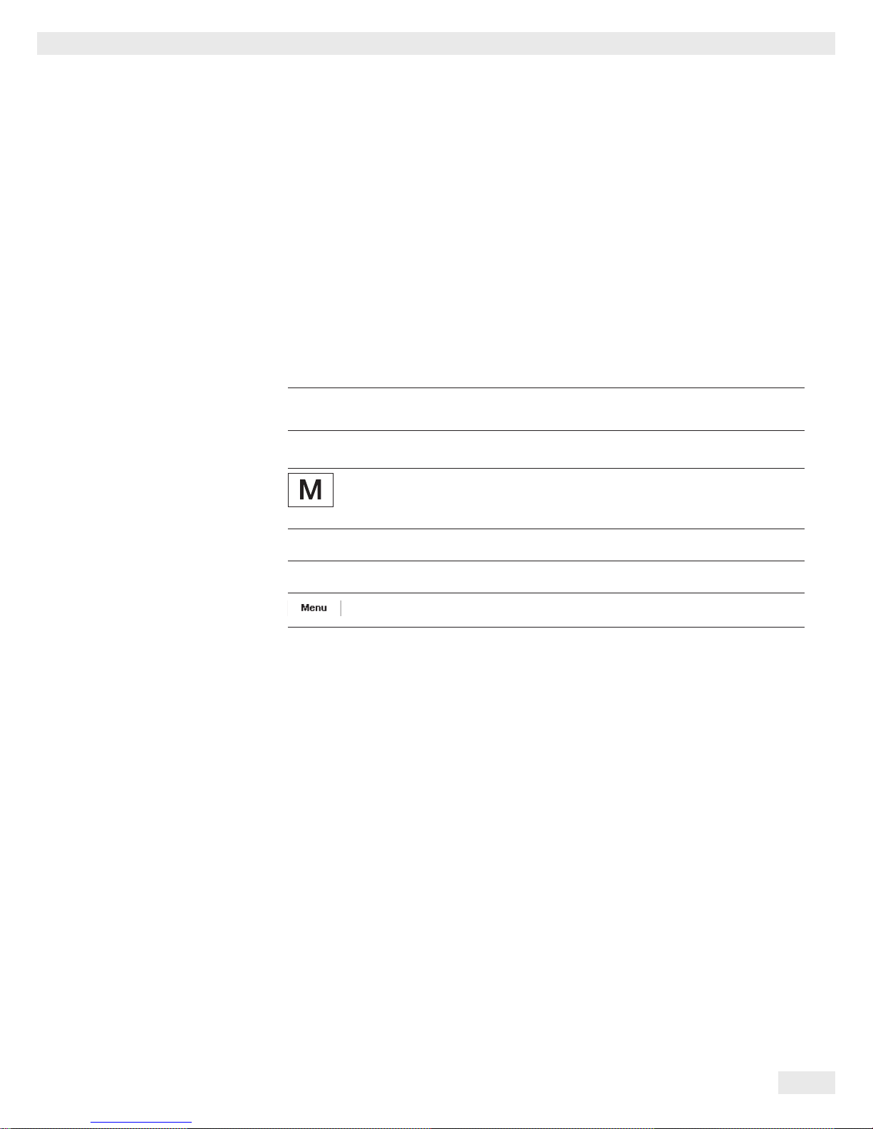
Microbalances: models MSU6.6S, MSU3.6P, MSU2.7S
Item Description
1 Weighing pan
2 Filter weighing pan d 50 mm
3 Internal draft shield (for MSU2.7S-F only)
4 Optional weighing pan d 75 mm
5 Shield disk
6 Optional weighing pan d 90 mm
7 Shield plate
8 Level indicator
9 Leveling foot
10 MSA2.7..model: socket
11 Draft shield cover
Item Description
12 Female connector for weigh cell
13 DC jack
14 Display and control unit
15 Serial communications port (PERIPHERALS)
16 Slot for optional interfaces
(e.g., 9-pin data output and PS2 or Bluetooth)
17 Lug for attaching antitheft locking device
18 Weigh cell connector - electronics module
19 Equipotential bonding conductor terminal
20 Draft shield
Not shown: AC adapter, USB cable
Use6
9719
87
1
2
3
4
5
6
7
8
9
10
11
12
13
14
15
16
17
18
7
1
3
19
Cubis® MSU User Manual 7
General View of the Equipment and Equipment Supplied
Models MSU66S, MSU66P, MSU36S, MSU36P
Item Description
1 Push handle/Handle
2 Inner draft shield
3 Weighing pan
4 Shield disc
5 Level indicator
6 Leveling foot
7 SD card slot
8 USB interface for PC connection
9 Weigh cell female connector
Item Description
10 DC jack
11 Display and control unit
12 Serial communications port (PERIPHERALS)
13 Slot for optional interface
(e. g. 9-pin data output and PS2 or Bluetooth)
14 Connection plug: Weigh cell – electronics module
15 Equipotential bonding conductor
16 Lug for attaching anti-theft locking device
Not shown: AC adapter, USB cable
1
16
15
6
14
Use6971
9
87
7
8
9
10
11
12
13
1
2
3
4
5
6
8 Cubis® MSU User Manual
General View of the Equipment and Equipment Supplied
Model MSU116P
Item Description
1 Push handle/Handle
2 Inner draft shield
3 Weighing pan
4 Shield disc
5 Level indicator
6 Leveling foot
7 SD card slot
8 USB interface for PC connection
9 Weigh cell female connector
Item Description
10 DC jack
11 Display and control unit
12 Serial communications port (PERIPHERALS)
13 Slot for optional interface
(e. g. 9-pin data output and PS2 or Bluetooth)
14 Connection plug: Weigh cell – electronics module
15 Equipotential bonding conductor
16 Lug for attaching anti-theft locking device
Not shown: AC adapter, USB cable
1
16
15
6
14
U
se69719
87
7
8
9
10
11
12
13
1
2
3
4
5
6

Cubis® MSU User Manual 9
General View of the Equipment and Equipment Supplied
General View of the Equipment
and Equipment Supplied
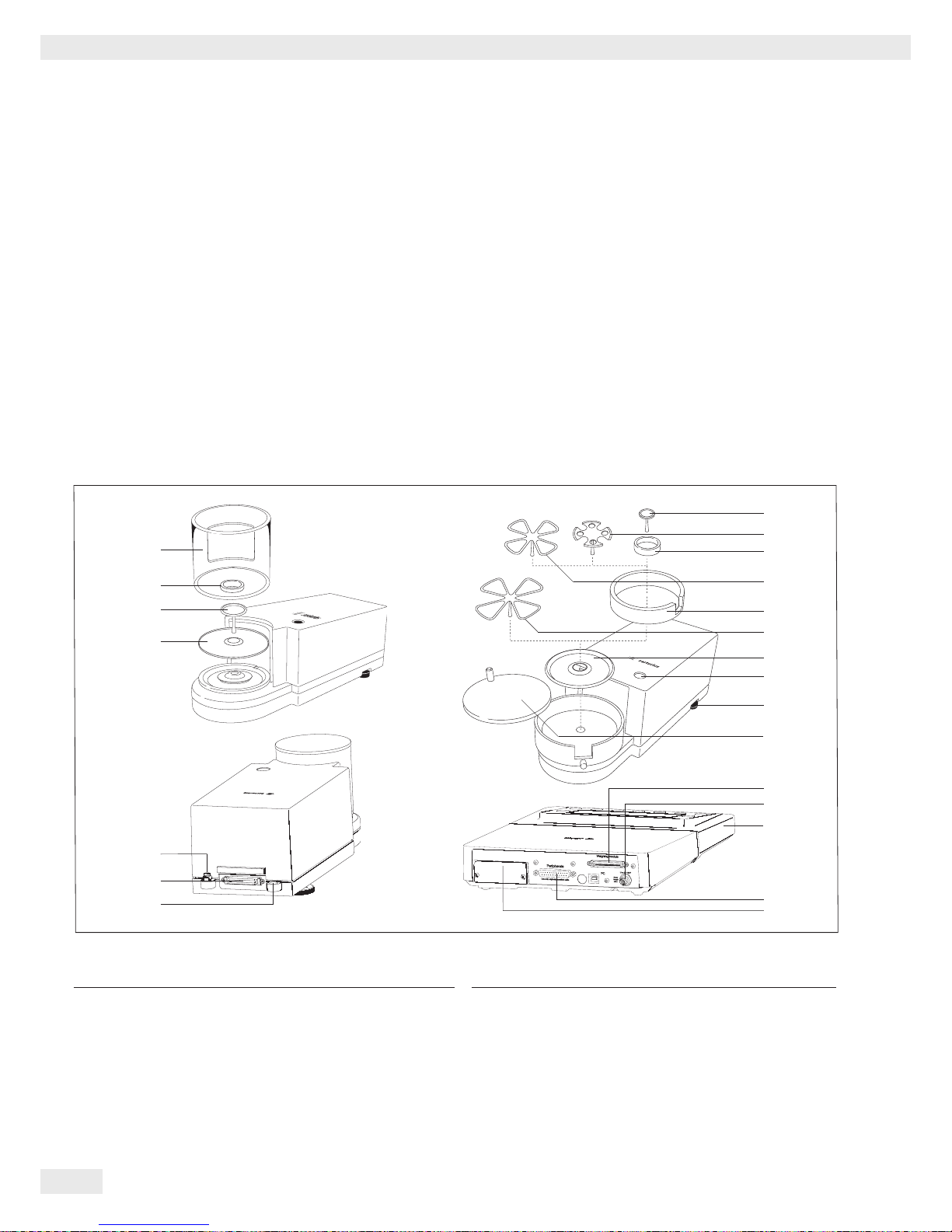
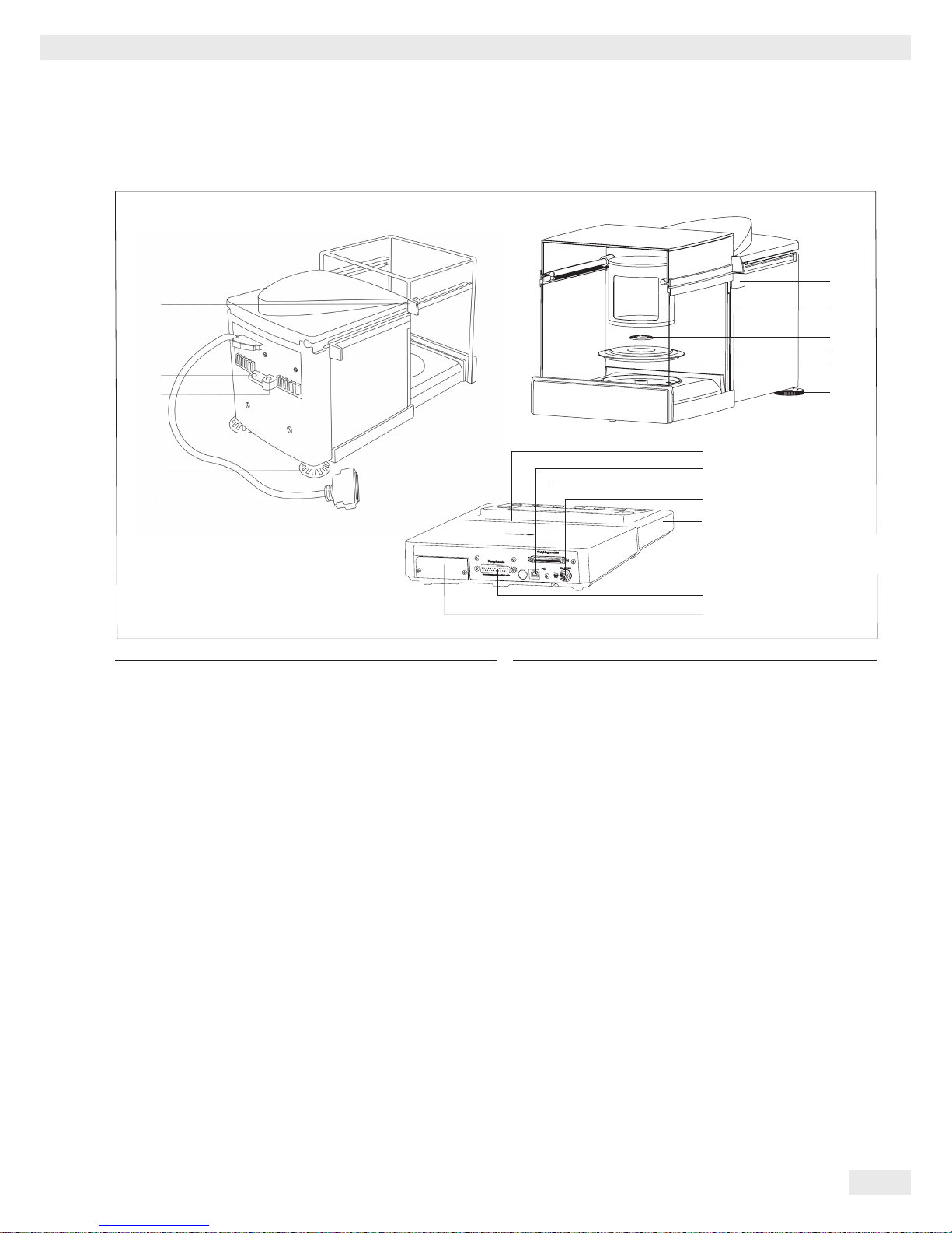
Analytical and precision balances with a weighing range of up to 15 kg
Item Description
1 Upper sliding draft shield panel/handle
2 Back panel
3 Weighing pan
4 Pan support (not for MSU225.../MSU125... models)
5 Shield plate
6 Pan retainer
7 Right sliding panel/handle
8 SD card slot
9 Leveling foot
10 Display
11 Display and control unit
12 Draft shield/Shield disk (only for models
with a readability of 1 mg and 10 mg)
13 Below-balance weighing port
(on the bottom of the balance)
14 Leveling foot
15 Level indicator
16 Power socket
17 Slot for attaching an anti-theft device
18 USB socket for a PC connection
19 Below-balance weighing hook
20 Slot for optional interfaces,
e.g., 9-pin data output and PS2 (as shown) or Bluetooth
21 Communication port (PERIPHERALS) for accessories
22 Menu access switch
23 Left sliding panel/handle
24 Ethernet interface
(on the bottom of the display and control unit)
25 Semi-microbalances: Female connector for weigh cell
26 Semi-microbalances: Electronics module
(for MSU225.../MSU125... models)
Not shown:
– AC adapter
– USB cable
– Operating instructions
10
11
23
3
4
5
5
6
6
13
13
11
11
14
14
6
12
12
4
3
3
15
16
17
18
19
20
21
22
4
25
26
15
17
20
21
22
1
2
3
4
5
6
7
9
8
24

10 Cubis® MSU User Manual
General View of the Equipment and Equipment Supplied
General View of the Equipment and Equipment Supplied
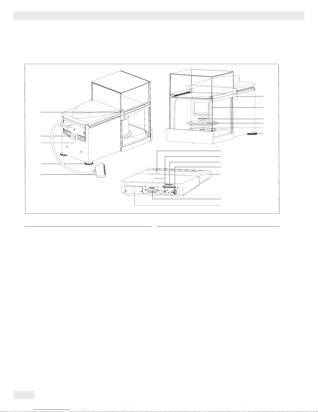
Balances with a weighing range of 20 kg or more
1
3
4
5
7
2
6
Item Description
1 DC jack
2 Leveling foot
3 Level indicator
4 Serial communications port (PERIPHERALS)
Item Description
5 USB socket for a PC connection
6 Display and control unit
7 Weighing pan
Not shown: AC adapter, USB cable
Cubis® MSU User Manual 11
Getting Started
Getting Started
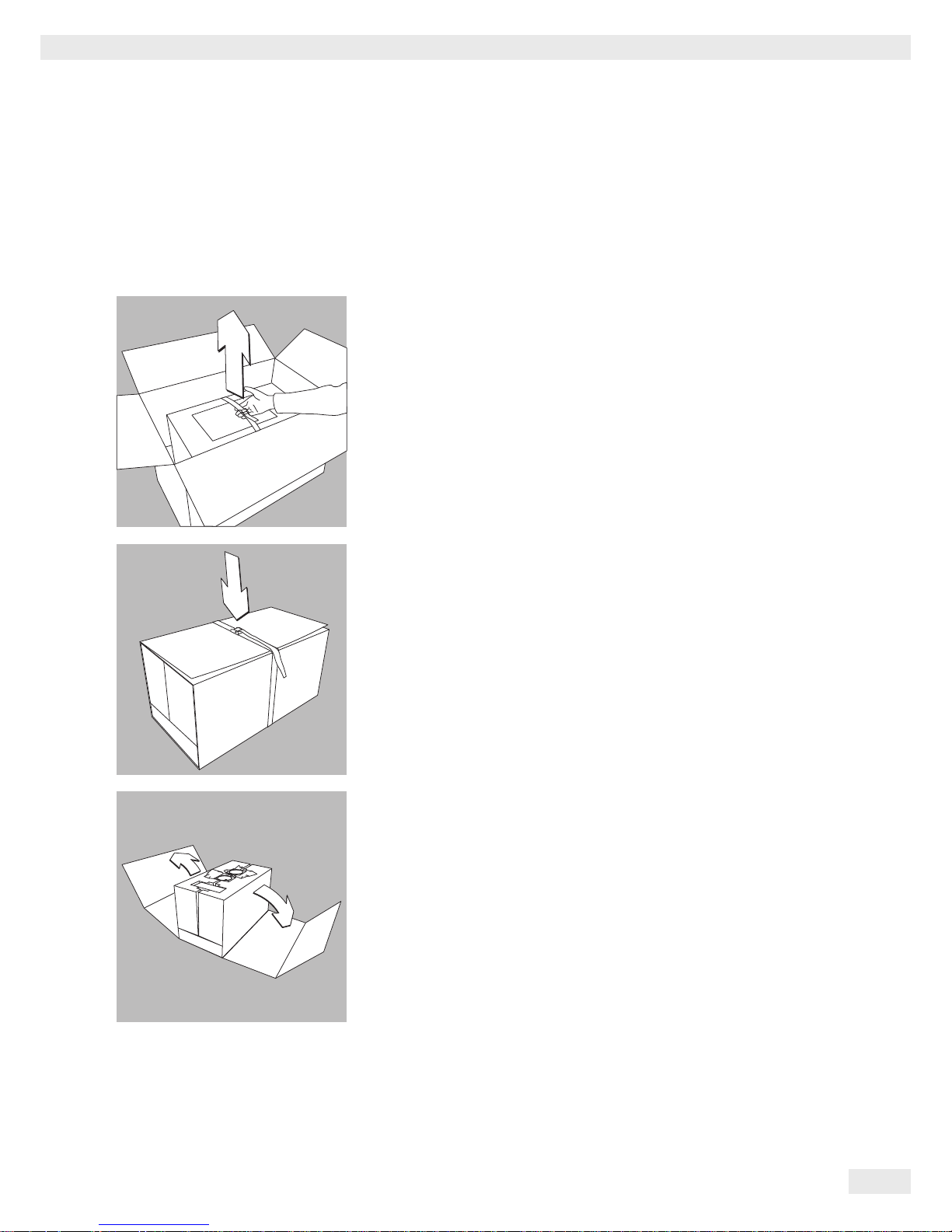
Unpacking
Models MSU116P, MSU66S, MSU66P, MSU36S, MSU36P:
t Lift the package containing the device out of the outer packaging by the strap.
t Loosen and remove the strap.
t Remove the cardboard sleeve.
12 Cubis® MSU User Manual
Getting Started
t Remove the following parts from the recessed spaces of the inner packaging:
− Weighing pan
− Shield plate
t Remove the lateral packaging paddings of the inner packaging by pulling out-
ward.
t Remove the retainer securing the front draft shield panel.
t Open the plastic wrapping.
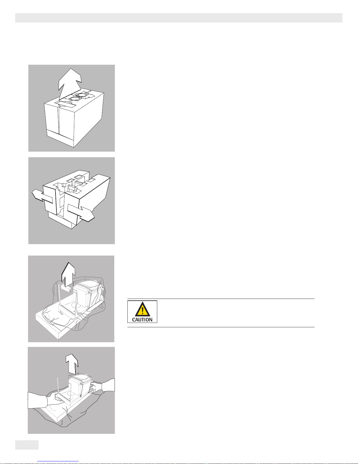
Exercise caution to avoid glass breakage.
Never lift the device by the draft shield panels to remove
it from the packaging.
t Place one hand under the front panel and the other under the back of the
housing and lift the device out of the lower packaging padding.

Cubis® MSU User Manual 13
Getting Started
Do not lift the device by the draft shield or the front panel since
this can result in damage.
t Place the device at the intended installation location.
t Open the draft shield doors.
t Remove the inner foam padding from the draft shield.
Save the box and all parts of the packaging in case it should
become necessary to transport the device. Only the original
packaging provides the best protection for shipment (see also
Shipping on page 36).
Before packing the device for shipping, unplug all connected
cables to prevent unnecessary damage.
Balance with the Analytical Draft Shield
t Open the packaging at the top.
t With both hands in the side impressions lift the balance, with the packaging,
out of the cardboard box.

14 Cubis® MSU User Manual
Getting Started
t Place the packaging with the balance on the floor.
t Remove the top part of the packaging.
t Remove the packages (containing draft shield panels, weighing pan, pan sup-
port, AC adapter, etc.) from the lower packaging and place them to one side.
3
Caution! Exercise caution to avoid glass breakage.
Never lift the device by the draft shield panels to remove it from the
packaging.
t Use both hands to lift the balance out of the packaging.
t Place the balance on an even surface.
Balance with No Draft Shield
t Use both hands to remove the model without a draft shield from the packag-
ing.
t Remove the AC adapter and the balance parts from the packaging.
Cubis® MSU User Manual 15
Getting Started
Assembly
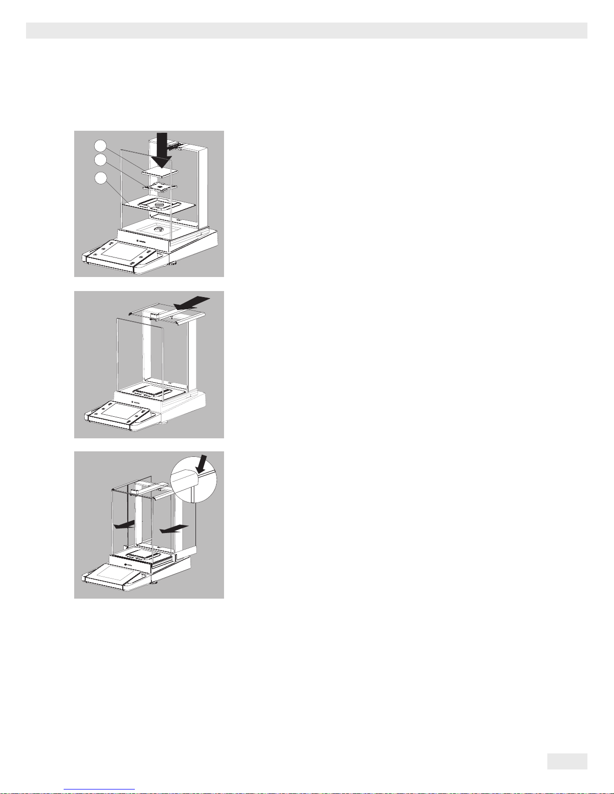
Installing the Analytical Draft Shield Labeled DA, DI, and DU
t Carefully fit parts onto the balance as shown in the picture.
1. Shield plate
2. Pan support (not for MSU225.../MSU125... models)
3. Weighing pan
t Slide the upper draft shield panel into the guide rails from the rear.
t Slide the left and right draft shield panels into the guide rails from the rear.
Make sure the panels are within the upper and lower guide rails.
t Slide the panels in until they engage.
1. Right draft shield panel
2. Left draft shield panel
y This completes the balance assembly.
2
1
3
16 Cubis® MSU User Manual
Getting Started
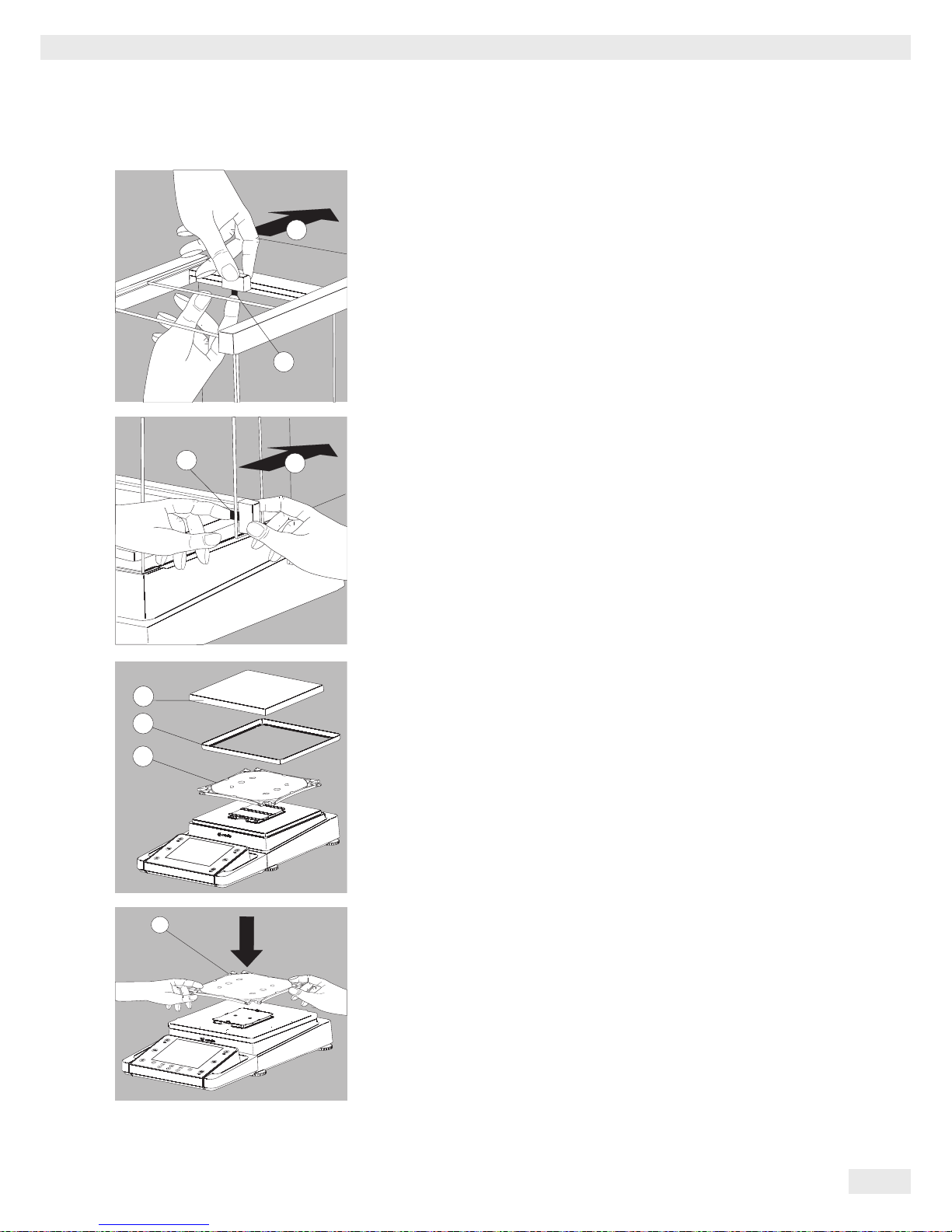
Installing the Draft Shield Labeled DE for Milligram Balances
t Carefully fit all parts as shown.
1. Shield plate
2. Pan support
3. Weighing pan
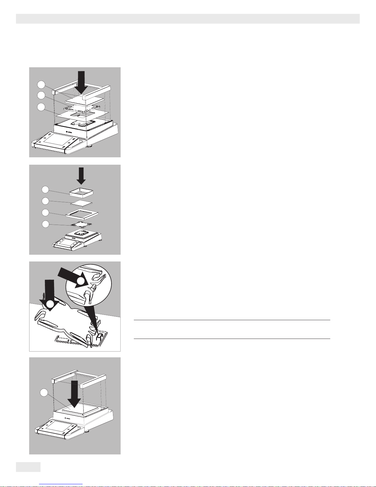
Assembly of Milligram Balances without Glass Draft Shield (DR Option)
t Fit all components listed below onto the balance in the order given:
1. Pan support (see also next section)
2. Shield plate
3. Weighing pan
4. Draft shield frame
t First insert the shield plate.
t Make sure the pin on the pan support is facing toward the front, and slide it
under the clip on the pan retainer.
1. Insert the pan support.
t After inserting the pan support, press it down against the shield plate so that it
lies flat.
3
Exercise caution to avoid pinching or crushing fingers.
2. Press down on the pan support
t Place the weighing pan (3) on the pan support.
2
1
3
1
2
3
4
3
2
1
3
1
2
3
4
2
1
3
Cubis® MSU User Manual 17
Getting Started
t Slide the upper draft shield panel into the guide rails from the rear while
pressing the locking tab.
t Slide the side draft shield panel into the guide rails from the rear while pressing
the locking tab.
y This completes the balance assembly.
t If necessary, remove the panel again:
1. Press on the locking tab
2. Remove the panel
t Place the panel in the storage slot at the back of the balance.
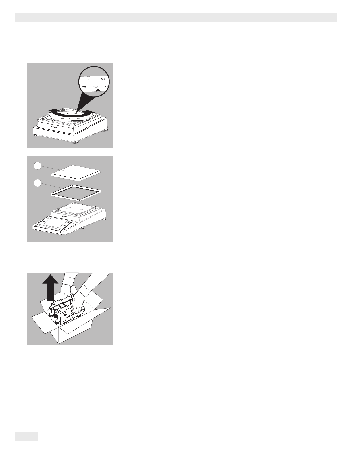
Assembling Precision Balances without a Draft Shield with a Weighing Range of
up to 15 kg
t Carefully insert all parts.
1. Pan support
2. Shield plate/Draft shield
3. Weighing pan
t Place the pan support (1) diagonally and press down lightly.
2
1
2
1
3
1
2
1
18 Cubis® MSU User Manual
Getting Started
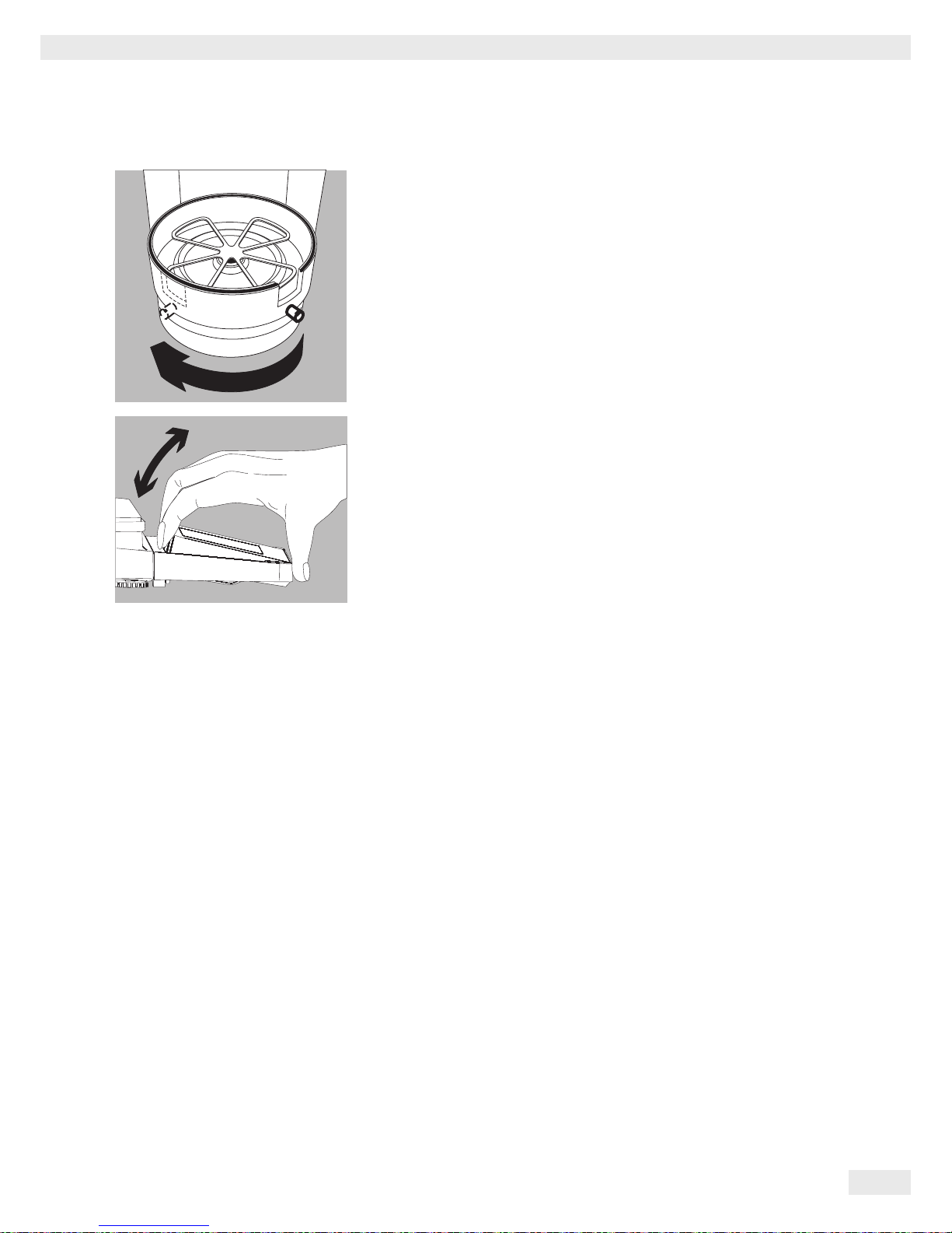
t Carefully turn the pan support clockwise until the two buttons engage.
The pan support is now attached.
t 2. Insert the shield plate/draft shield.
t 3. Place the weighing pan on the pan support
y This completes the balance assembly.
Balance with the Analytical Draft Shield
t Open the packaging at the top.
t With both hands in the side impressions lift the balance, with the packaging,
out of the cardboard box.
2
3
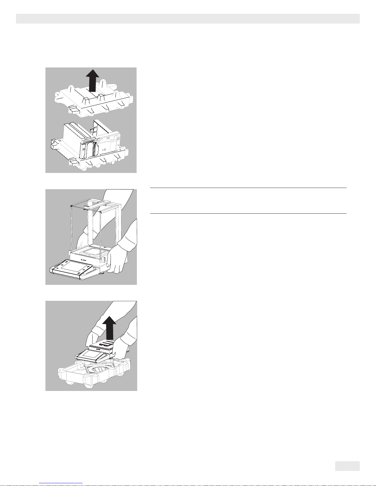
Cubis® MSU User Manual 19
Getting Started
t Place the packaging with the balance on the floor.
t Remove the top part of the packaging.
t Remove the packages (containing draft shield panels, weighing pan, pan sup-
port, AC adapter, etc.) from the lower packaging and place them to one side.
3
Caution! Exercise caution to avoid glass breakage.
Never lift the equipment by the draft shield panels to remove it from the
packaging.
t Use both hands to lift the balance out of the packaging.
t Place the balance on an even surface.
Balance with No Draft Shield
t Use both hands to remove the model without a draft shield from the
packaging.
t Remove the AC adapter and the balance parts from the packaging.
20 Cubis® MSU User Manual
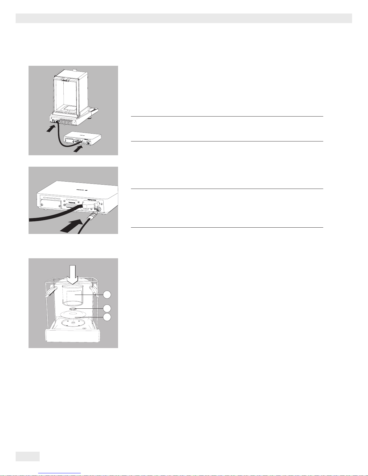
Getting Started
Models with an External Electronics Module: Connecting the Weigh Cell to the
Electronics Module
t Connect the weigh cell and electronics module using the connection cable:
Make sure that the connectors click into place so that both ends engage
correctly.
3
Check the plug contacts to ensure that the connection is correct.
There should be no tension on the connection cable, e.g. if pushed
directly against a wall.
t Connecting the Weigh Cell to the Evaluation Unit:
Make sure that the connector clicks into place so that the cable is engaged.
3
Models with a separate electronics module (e.g. MSU66/36/6.6/3.6/2.7,
MSU225S/P, MSU125P and MSU116P):
Do not mix up the eletronics module.
Interchanging with, e.g. models of the ME/SE series will damage the
device.
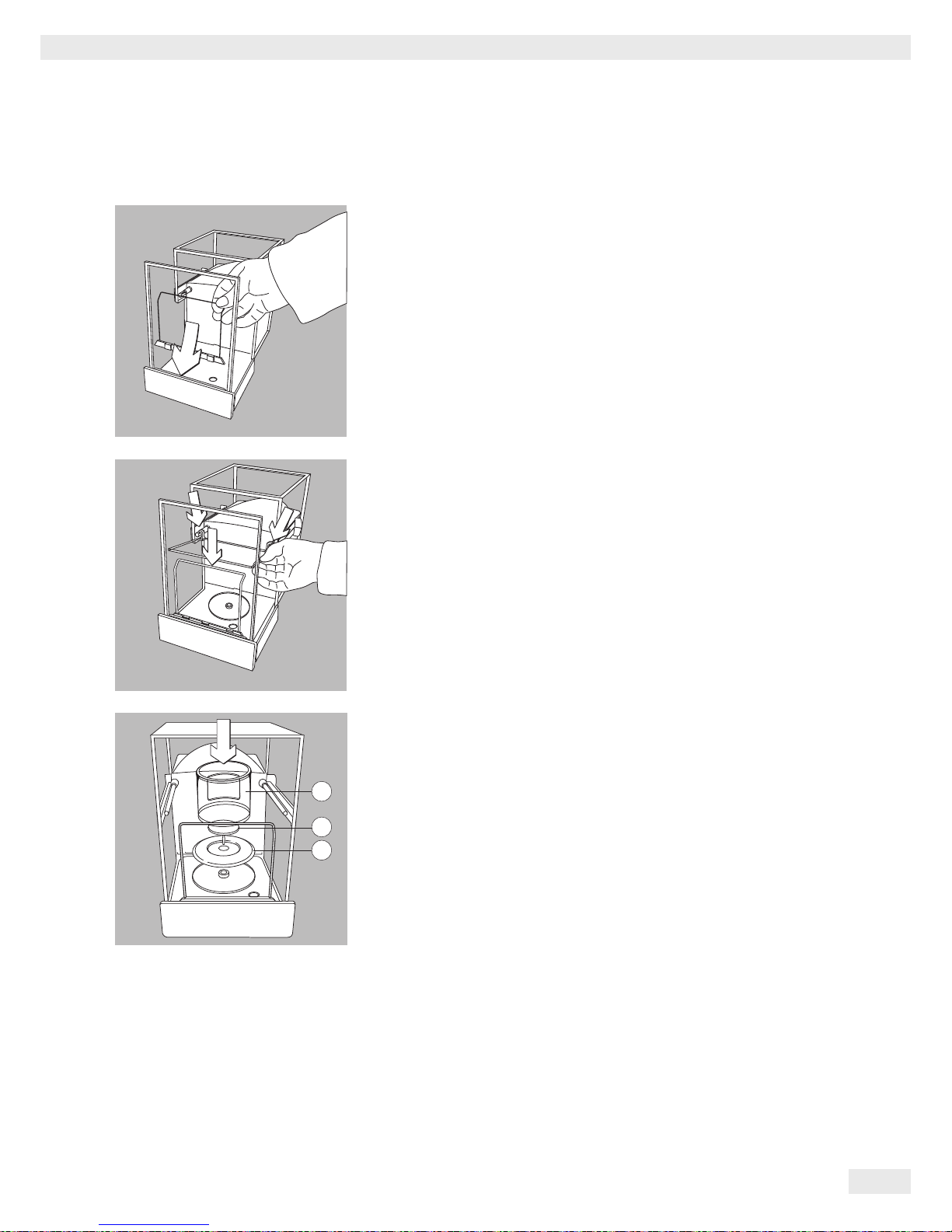
Models MSU66 and MSU36: Placing components into weighing chamber
t Insert the following components into the weighing chamber in the order given:
1. Shield disk
2. Weighing pan
3.
Internal draft shield
1
2
3
Cubis® MSU User Manual 21
Getting Started
Model MSU116P: Placing components into the weighing chamber
t Position the support bracket directly behind the front panel.
t Position the glass panel in the retainers and place it at the back of the draft
shield.
t Place the components listed below inside the weighing chamber in the order
given:
1. Shield plate
2. Weighing
pan
3. Internal draft shield
1
2
3

22 Cubis® MSU User Manual
Getting Started
Models MSU6.6S/3.6P/2.7S: Placing Components on the Weigh Cell
t Place the following Parts in the order listed:
t 1. Shield plate
t 2. Shield plate
t 3. Weighing pan
Tip:
After inserting the weighing pan, turn it slightly to the left and right
while pressing it down lightly.
t 4. Internal draft shield (for SE2 only)
t 5. Draft shield: Center the hole over the pan (see arrows).
Filter Balances (models MSU6.6S-F/2.7S-F): Placing Components on the
Weigh Cell
t Place the components on the weigh cell in the order given:
t 1. Model MSU2.7S-F: Connector
t 2. Shield plate
t 3. Internal draft shield
t 4. Filter weighing pan d 50 mm or weighing pan
(optional filter weighing pan d 75 mm or d 90 mm)
Note: After inserting the pan, turn it slightly to the left and right,
while pressing it down lightly.
t 5. Draft shield cover
! Notice
Turn the balance off and then on again after replacing the pan during
operation.
Setting up a filter weighing pan for left-handed users:
t Remove the draft shield cover
t Unscrew the pin and move from the right to the left side
3
2
4
5
1
MSU6.6S/3.6P/2.7S:
MSU6.6S-F/2.7S-F:
Cubis® MSU User Manual 23
Getting Started
t Turn draft shield parts approx. 90 degrees to the left (loosen knurled screw).
Setting the Angle for the Display and Control Unit
The angle of the display unit can be adjusted by the user in order to ensure optimal
readability of the weight values on the display at all times.
t The display and control unit can be tilted as desired.
Choosing a Location
t Selecting the right setup location:
– Set up the device on a stable, even surface that is not exposed to vibrations
(e.g., weighing stone).
– Place the device in a location with enough free space around it so that
excessive heat cannot build up.
– Maintain free access to the device at all times.
– The balance may only be used in closed spaces and at a max. height above
sea level (see, chapter Techn. Data, “Ambient conditions”).
Choose a location that is not subject to the following negative influences:
– Heat (heater or direct sunlight)
– Drafts from open windows, AC systems, and doors
– Extreme vibrations during measurement
– Extreme humidity
For further information, please refer to the “Proper handling of analytical balances
and microbalances” document.

24 Cubis® MSU User Manual
Getting Started
Acclimatization
Condensation from humidity can form on the surfaces of a cold device when it is
brought into a substantially warmer area.
Allow the device to acclimatize for about two hours at room temperature, leaving it
unplugged from the power supply.
Carefully read all warnings and safety precautions in the respective section of this
manual.
Power Connection
t Check the voltage rating and plug design.
– Make sure that the voltage rating printed on the manufacturer’s ID label is
identical to that of your local mains voltage.
– If the stated supply voltage or the plug design of the power cord does not
comply with your country’s standard, please inform the nearest Sartorius
representative or your dealer.
– The power must be connected in accordance with the regulations applicable in
your country.
– In order to connect the equipment to the power supply (protection class 1),
use a suitable, correctly installed wall outlet with a protective grounding
conductor (PE) and a fuse of a maximum of 16A.
– Only use original Sartorius AC adapters.
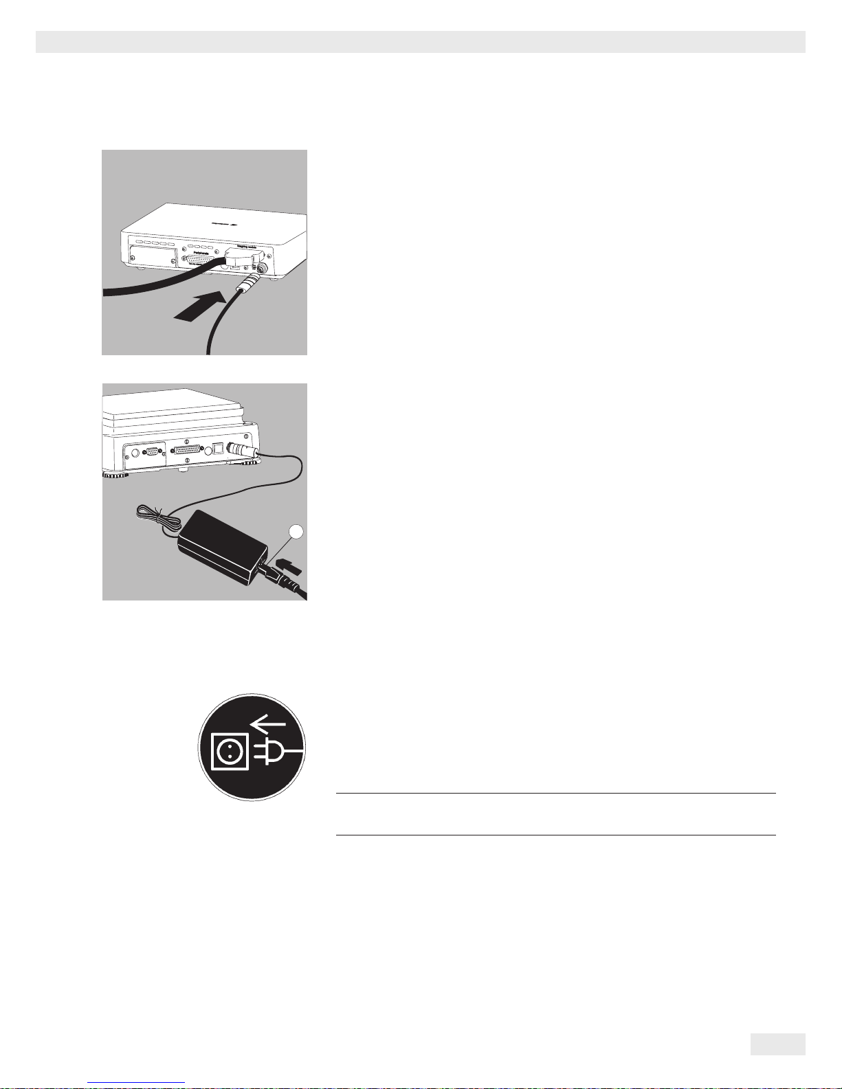
Analytical and precision balances:
1. Plug the DC supply cable of the AC adapter into the power socket of the
balance and tighten the threaded fitting.
°C
1
Cubis® MSU User Manual 25
Getting Started
Balances with a readability of ) 0.01 mg
1. Plug the DC supply cable of the AC adapter into the power socket of the
electronics module and tighten the threaded fitting.
2. Plug the power cord into the AC adapter.
3. Insert the AC adapter plug into the wall outlet.
y The balance is now ready to use.
Safety Precautions
The output line of the adapter has a terminal (GND) connected to the metal
housing of the balance. The data port is also galvanically linked to the balance
housing (GND).
Connecting Electronic Devices (Peripherals)
t Make absolutely sure that the device is unplugged from the power supply
before connecting/disconnecting any peripheral device (printer, scanner, PC)
to or from the data port.
3
A device connected to the power supply should never be opened.
2
26 Cubis® MSU User Manual
Getting Started
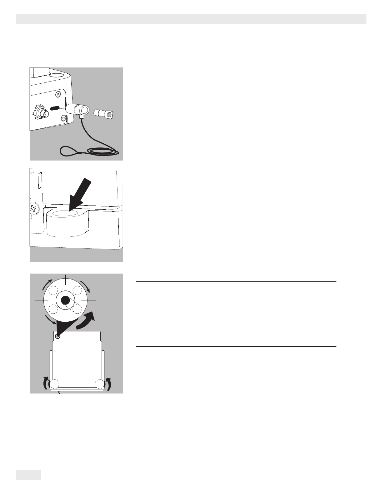
Anti-Theft Locking Device (Accessory)
Balances with a readability of ) 0.01 mg:
t An anti-theft locking device can be installed to the back of the balance if
required.
Balances with a readability of ) 1 μg:
To fasten the anti-theft locking device, use the lug located on the back of the
weigh cell.
Leveling
h
Leveling the balance compensates for slant or unevenness at the
place of installation. The scale must be perfectly horizontal to ensure
consistent, reproducible weighing results. All models are equipped with
an electronic tilt angle detection feature. If the balance is not level, a
warning message appears on the display.
Push-button automatic leveling is available on models with motorized
leveling feet. For models with manual leveling feet, please follow the
instructions on the display.
Leveling the Balance Manually
y The scale is leveled using both front leveling feet.
t Screw in both back leveling feet (only for models with back leveling feet).
t Turn the front leveling feet as shown in the illustration until the air bubble is
centered within the circle of the level indicator.
y Normally, several leveling steps are required
t Turn both back leveling feet until they touch the setup surface (only for models
with back leveling feet).
R
L
L
L
R
R
Cubis® MSU User Manual 27
Getting Started
Switching On
t Turn on the device via the A key. The following appears on the display:
y You can now follow the brief instructions to configure further necessary
balance settings before beginning weighing operations.
Warm-up Time
y To deliver precise results as per the Specifications, the balance must warm up
for at least 30 minutes after initial connection to the power supply. Only then
will the device have reached the required operating temperature.
When a verified balance used in legal metrology (legal-for-trade
applications) is connected to the power, it must warm up for at least
two hours before operation.
12
6
93
2
28 Cubis® MSU User Manual
Getting Started
Modifying the Balance
Setting Up the Display and Control Unit at the Place of Use
The display and control unit can be removed for all models to enable the operator
to customize the work space.
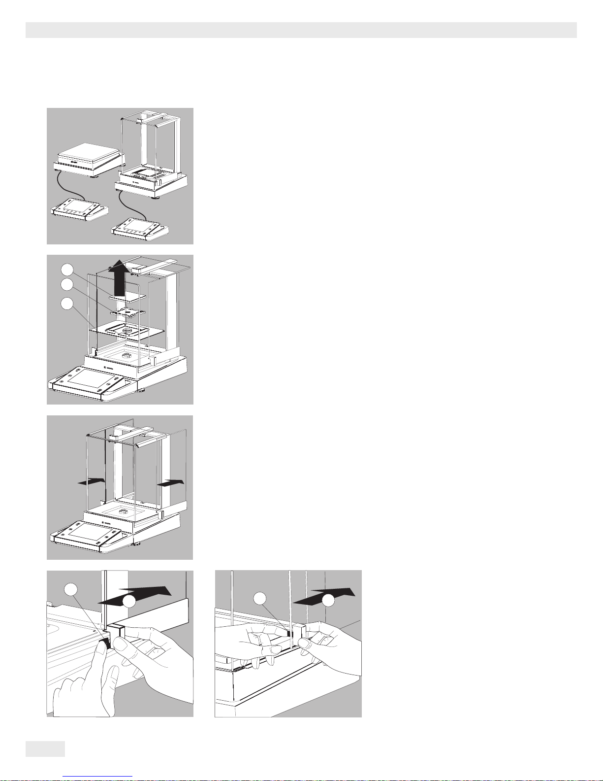
Removing the Retainer with the Display and Control Unit
Analytical balances:
t Remove all items (such as weights) from the draft shield.
t Carefully remove all parts as shown in the illustration.
1. Weighing pan
2. Pan support (not for models MSU225.../MSU125...)
3. Shield plate/Draft shield
t Keep all parts in a safe place.
t Remove the panels (right and left).
Models with the analytical draft shield:
1. Press on the locking tab
2. Remove the panel
Models with the milligram draft shield:
1. Press on the locking tab
2. Remove the panel
t Keep all parts in a safe place.
2
1
3
2
1
2
1
Cubis® MSU User Manual 29
Getting Started
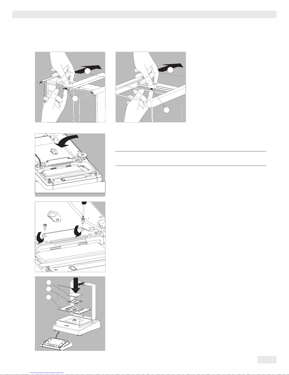
t Remove the upper draft shield
panel.
Models with the analytical draft shield
(left illustration):
1. Press on the locking tab
2. Remove the panel
Models with the milligram draft shield
(right figure):
1. Press on the locking tab
2. Remove the panel
t Keep all parts in a safe place.
t Turn over the balance and place on a soft surface.
3
Exercise caution to avoid breaking the glass on models with a draft shield.
t Use a 2.5 mm Allen wrench to remove the two screws from the display and
control unit retainer bracket.
t Remove the display and re-insert both screws back into their holes.
t Lengthen the cable and position the display and control unit as desired.
t Turn the balance over and place it on an even surface.
t Carefully place all parts on the balance.
1. Shield plate/Draft shield
2. Pan support (not for models MSU225.../MSU125...)
3. Weighing pan
2
1
2
1
2
1
3
30 Cubis® MSU User Manual
Getting Started
t Replace the upper and side shield panels.
1. Upper draft shield panel
2. Right draft shield panel
3. Left draft shield panel
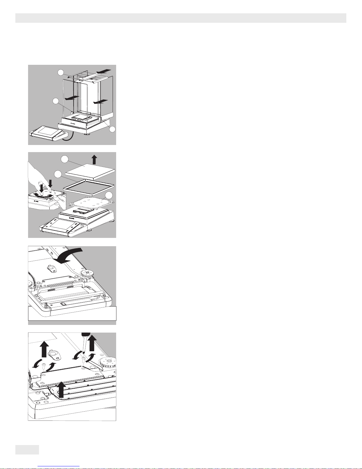
Removing the Display and Control Unit from Precision Balances without a Draft
Shield with a Weighing Range of up to 15 kg
t Carefully remove all parts as shown in the illustration.
1. Weighing pan
2. Shield plate/Draft shield
3. Pan support
t Keep all parts in a safe place.
t Turn over the balance and place it on a soft surface.
t Remove the two retaining screws.
t Remove the display and re-insert both screws back into their holes.
t Carefully pull the cable connected between the display and control unit from
the retainer.
3
2
1
2
1
3
 Loading...