

Page 1
WCP5001-e07104
Service Manual
Sartorius Competence | Sartorius Gem
plus
CPA-, CP-, GC- und GP-Models
Electronic Semimicro-and Analytical Precision Balances and Precious Metal Scales
Including Service Specifi cations Sheets
Page 2

2 | Contents
Page
03 General Information
03 Fundamentals at a Glance
04 The Most Important Information at a Glance
04 Service Concept for the CP/GC/GP Scale/
Balances
04 General Notes
05-06 New Features Compared to the BP
06-07 Models with Special Weighing Systems
08 Auxiliary Service Tools, Equipment and Weights
08 Accompanying Literature
09 Handling and Operation
09 Function of the Keys
09 Displaying the Hardware and Software Versions
10 Function of the Service Switch and Access Lock
Switch
10 Access Lock Switch
11 Brief Instructions Balance/Scale Operating Menu
11-12 Accessing and Setting the Balance/Scale Opera-
ting Menu
13-14 Menu Code Settings(Rel BAC 13.44 Version)
15 Function of the BPI Switch
15 Activating the BPI Mode
16 Testing and Adjusting Balances/Scales with Strain
Gauge Systems
16 Testing and Adjustment Sequence on Balances/
Scales with Strain Gauge Systems
16 Checking the Overload Stop
16 Setting the Overload Stop
17 Zero-Point Offset Adjustment
17 1. Adjustment with a Digital Voltmeter
17 2. Adjustment using the Service Software
(Sartocas / Psion)
18 Checking the Repeatability (standard deviation)
18 Checking and Adjusting the Off-Center Loading
Error
18 Checking the Off-Center Loading Tolerances
19-20 Procedure for Adjusting the Off-Center Loading
Error (Strain Gauge)
21 Span Adjustment
21 External Adjustment
22 Adjusting Linearity
22 Adjusting External Linearity
23 Testing and Adjusting Balances/Scales with Double-
Lever Systems
23 Testing and Adjustment Sequence on Balances/
Scales with Double Lever Systems
23 Checking the Overload Stop
23 Checking the Repeatability (standard deviation)
24 Checking and Adjusting the Off-Center Loading
Error
24 Checking the Off-Center Loading Tolerances
25 Procedure for Adjusting the Off-Center Loading
Error (Double Lever Systems)
26 Span Adjustment
26 External Adjustment
27 Adjusting Linearity
27 Adjusting External Linearity
28 Balance/Scale with Monolithic Weigh Cells
28 Testing and Adjustment Sequence on Balances/Scales
with Monolithic Weigh Cells
28 Checking the Overload Stop
28 Checking the Repeatability (standard deviation)
29 Off-Center Loading Error
29 Checking and Adjusting the Off-Center Loading Error
29 Checking the Off-Center Loading Tolerances
29 Procedure for Adjusting the Off-Center Loading
Error (Monolithic Weigh Cells)
30 3-Point Adjustment
31 Span Adjustment
31 External Adjustment
31 Overwriting the Internal Calibration Weight
32 Internal Span Adjustment
33 Linearity
33 Checking the Linearity
33 Adjusting the Linearity
34 Overwriting the Internal Linearization Weight
35 Balances/Scales with Forked Lever Systems
35 Testing and Adjustment Sequence on Balances/Scales
with Forked Lever Systems
35 Checking the Overload Stop
35 Checking the Repeatability (standard deviation)
36 Off-Center Loading Error
36 Checking and Adjusting the Off-Center Loading
Tolerances
36 Procedure for Checking the Off-Center Loading
Tolerances
37 Procedure for Adjusting the Off-Center Loading
Error (Forked Lever Systems)
38 External Adjustment
39 Linearity
39 Checking the Linearity
39 Adjusting the Linearity
40-41 Error Codes
42-44 Calibration/Adjustment Data
Page 3

General Information | 3
Generals Information
Fundamentals at a Glance
We strongly recommend completing a service training course at
Sartorius before performing work on Sartorius weighing instruments.
Please do not attempt or permit any unauthorized repair work.
The following CP models will be/have been replaced by CPA models:
Standard models:
CP - Models = Nachfolger CPA CP - Models = Nachfolger CPA
CP64 = CPA64 CP124S = CPA124S
CP224S = CPA224S CP324S = CPA324S
CP225D = CPA225D CP34000 = CPA34000
CP4201 = CPA4201 CP6201 = CPA6201
CP8201 = CPA8201 CP12001S = CPA12001S
CP16001S = CPA16001S CP34001S = CPA34001S
CP34001S = CPA34001S CP622 = CPA622
CP2202S = CPA2202S CP3202S = CPA3202S
CP4202S = CPA4202S CP153 = CPA153
CP323S = CPA323S CP423S = CPA423S
Important Note: All CPA models have an overlay that is different from the one on CP
models (see page 9).
The analytical balances with model names CPA324S and CPA224S and
higher have a monolithic weigh cell.
stamp approved models: CP - Models = Nachfolger CPA CP - Models = Nachfolger CPA
CP124S-ACE = CPA124S-PCE CP12001S-0CE = CPA12001S-0CE
CP224S-PCE = CPA224S-PCE CP16001S-0CE = CPA16001S-0CE
CP64-0CE = CPA64-0CE CP34001S-0CE = CPA34001S-0CE
CP124S-0CE = CPA124S-0CE CP622-0CE = CPA2202S-0CE
CP224S-0CE = CPA224S-0CE CP2202S-0CE = CPA2202S-0CE
CP324S-0CE = CPA324S-0CE CP3202S-0CE = CPA3202S-0CE
CP225D-0CE = CPA225D-0CE CP4202S-0CE = CPA4202S-0CE
CP523S-PCE = CPA523S-PCE CP153-0CE = CPA223S
CP3202S-ACE
CP4202S-PCE
CP4202S-ACE = CPA4202S-PCE
CP34000-0CE = CPA34000-0CE
CP34001P-0CE = CPA34001P-0CE
CP2201-0CE = CPA2201-0CE
CP6201-0CE = CPA5201-0CE
CP8201-0CE = CPA8201-0CE
Page 4

4 |
Service Concept for CPA/CP/GC/GP Balances/Scales
Valid until further notice
- All calibration/adjustment work required for starting up operations and testing
must be carried out in accordance with the operation instructions.
- Quality defects.
o Immediately report all quality defects that may occur to the Quality
Assurance Department (WQM).
- Defective balances/scales
o Warranty.
• Within the first 6 months of installation, any defective balance/scale
covered by the warranty should be exchanged.
o Seal of warranty.
• If you have to remove the Seal of Warranty, please affix your control seal
with the Sartorius logo to the unit!
o In other cases, proceed according to the OAW135 (standard operating
procedure for returns for repairs).
• Defective weighing cells.
Proceed as described in the Service Concept for Weighing Cells, refer to
(Service Information Document 6.2001 / OAW135-2/3).
• Defective electronics.
These balances/scales along with an error record should be sent back to
the Central Mechanics Workshop (ZW) in Goettingen (OAW135-2).
• Other service situations can be dealt with on site, for example:
Broken draft shields; weighing pan can no longer be used;
replacing small parts, ... etc.
General Notes
Transport:
- Always turn off the CP/GC balance/scale first by pressing the e button and
then wait about 10 seconds before you pull the mains plug.
If the balance/scale with an internal calibration weight is currently running
in the calibration mode, the internal calibration weights are exposed. This can
cause the weighing system to be damaged during transport. By switching off the
balance/scale properly, they will be locked.
- Before you plug in or remove any connecting cables, always separate the balance/
scale from the power supply, as otherwise components can become destroyed.
positioned How to change the battery:
upright fl at Important Note!
When exchanging the battery (if available), be sure that
- you use a new battery that is identical to the old one or equivalent to the
battery recommended by the manufacturer.
- the poles are correctly positioned when soldering in the battery.
Warning: If you use the wrong battery, this may result in an explosion.
Be sure to dispose of the defective battery properly according to your country‘s
environmental protection laws!
Generals Information
Aut_5007a.jpg
Aut_5006a.jpg
Page 5

| 5
New Features Compared to the BP: New, different housings (see Overview, Page 6)
Procedure: Checking the balance/scale 1. Check the repeatability
Balance/Scale with strain gauge system (standard deviation, see page 18)
Balance/Scale with double lever system (standard deviation, see page 23)
Balance/Scale with monolithic weigh cell (standard deviation, see page 28)
Balance/Scale with forked lever system (standard deviation, see page 35)
2. Checking the off-center loading error and adjust as required
Balance/Scale with strain gauge system (see page 18)
Balance/Scale with double lever system (see page 24)
Balance/Scale with monolithic weigh cell (see page 29)
Balance/Scale with forked lever system (see page 36-37)
3. Adjusting the sensitivity with internal calibration weight
Balance/Scale with monolithic weigh cell (see page 32)
4. Adjusting the sensitivity with external calibration weight
Balance/Scale with strain gauge system (see page 21)
Balance/Scale with double lever system (see page 26)
Balance/Scale with monolithic weigh cell (see page 31)
Determine the internal calibration weight as required (see page 31)
balance/scale with forked lever system (see page 38)
5. Adjusting the linearity is preferably performed using the sequential method, or
with calibrated weights,
Balance/Scale with strain gauge system (see page 22)
Balance/Scale with double lever system (see page 27)
Balance/Scale with monolithic weigh cell (see page 33)
Check the internal linearization weights as required (see page 34)
Balance/Scale with forked lever system (see page 39)
Activating the BPI Mode/ Perform only before working with the SARTOCAS Program or PSION; for calibration/
Deactivating write-protect adjustment. Linearization and programming a data record when exchanging the
main PCB.
Reset write-protect After working with the SARTOCAS program or PSION, always make sure to conclude
with the „Close“ function (returning the balance from BPI back to SBI mode),
otherwise write-protect is not set, and the balance/scale remains in the BPI mode
(see Page 11). If all else fails, reset the SBI mode by pressing menu reset (9-1°).
Exchanging the Main PCB When ordering replacement PCBs, always state the model and the serial number, that
is the only way that a new preprogrammed PCB set can be delivered.
Opening the housing - Unscrew the 1 (sealed) screw on the reverse side and slide the upper half of
the housing back.
- After reclosing the balance/scale, the service technician or service organization
must reaffi x another control seal!
Triangular weighing pan - Check the off-center loading error according to the OIML Recommendation R76,
see 4-point test (Pages 18; 24; 29)
- when carrying out adjustment/calibration work using the 3-point test (page 30)
Blue backlighting - Is adjustable and can be switched off
Service software - TradeCAS or SartoCAS starting with Version 1.44
Psion CAS Version 4.9 and later.
Do not use older software versions!
Adjusting the off-center load - On strain gauge, Angled lever and double lever systems perform by fi ling on
monolithic weigh cell with adjustment screws
Service Guide
Page 6
6 |
Models with Special Weighing Systems
Weighing systems - Strain gauge on low-resolution balances/scales,
Double lever system and forked lever system on high resolution precision balances
Monolithic weigh cells on analytical balances
Span adjustment - With external weights on precision balances not verifi ed for legal metrology
- With built-in weights on analytical balances and precision balances verifi ed for
legal metrology
Linearity - Is internally possible using (2 built-in weights) on analytical balances,
- On other models with external service software (CAS, PC/ PSION)
Menu locking - Menu access can be blocked by entering code (8-1-2) of the balance/scale
operating program
- The access lock switch is only functional on calibration models (calibration/
adjustment externally blocked)
BPI switch - (BPI = Binary Processor Interface) to prepare for working with CAS service
software, log out with „CLOSE“ function
- Or if all else fails by resetting the operating menu (9-1°)
Be careful, the factory settings are activated.
ERR 30 is also shown after pressing the p key, if the wrong interface cable
is used!
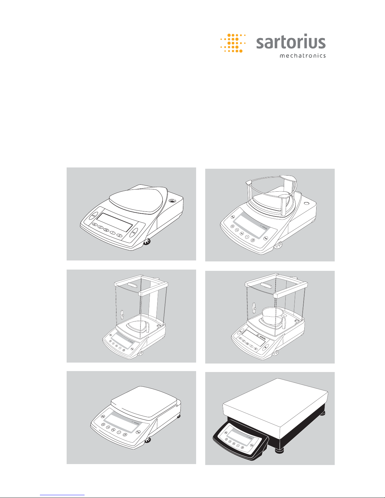
Models with Special Weighing Systems
Model 1
Weighing system: Strain gauge
(Strain gauge) (see right)
CP622
Model 2
Weighing system:
Strain gauge (see right)
CP8201, CP6201, CP4201, CP2201,
GP8201
Weighing system:
Angled lever (see below, right)
CP4202S, CP3202S, CP3202P,
CP2202S, GP5202, GP3202
CP_01b.eps
CP_01b.eps
CP_01.eps
Aut_4906.jpg
Aut_4910.jpg
Aut_4915.jpg
Page 7
| 7
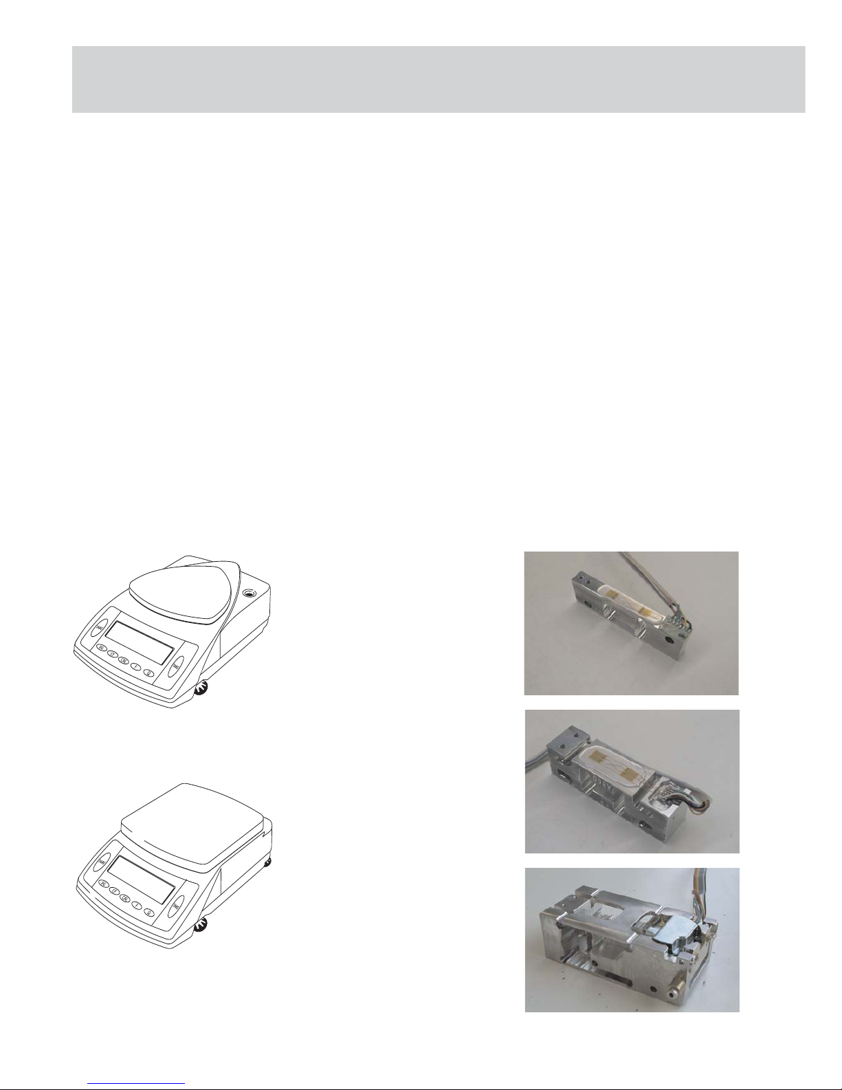
Model 3
Weighing system:
Angled lever (see right)
CP423S, CP323S, CP323P, CP153
Model 3
Weighing system:
Angled lever (see right)
GC2502
Model 4
Weighing system:
Monolithic (see right)
CP225D, CP324S, CP224S, CP124S,
CP64, GC1603, GC803S, GC803P
Model 5
Weighing system:
Fork lever (see right)
CP34001S, CP34001P, CP34000,
CP16001S, CP12001S
CP2_11.eps
CP_06.eps
Aut_4920.jpg
Aut_5254.jpg
CP2_01.eps
CP2_02.eps
Aut_5259.jpg
Aut_5259.jpg
Page 8

8 |
Auxiliary Service Tools, Equipment and Weights
Caution: After removing the seal (warranty label) and fi nishing service work, reaffi x your
control seal with the Sartorius logo!
Please make sure that you use the proper tools and equipment and that the
balance/scale is set up on a solid, level surface and in a clean work area that is free
of vibrations and drafts.
PSION CAS Version 4.9 and later
Service software CAS for PC Version 1.44 or later 6740-33
and
RS232 connecting cable (25-Pin) 7357312
or
RS232 connecting cable (9-Pin) 7357314
Tool Kit Angled fi le 6740-80
In addition to your standard tools and equipment, you will need the following sets of
weights when working on Sartorius Competence balances/scales:
For Model Accuracy Weight Catalog No.:
CPxxxx-CPAxxxx class (OIML) in grams
CP64 E2 1x50 YCW4528
CP124S, GC803 S/P E2 1x100 YCW5128
CP323P, CP153 F1 1x100 YCW5138
CP225D, CP224S E2 1x200 YCW5228
CP324S, GC1603P E2 1x200+ YCW5228 +
1x100 YCW5128
CP423S, CP323S,
GC 2502 F1 1x200 YCW5238
CP622 F2 1x500 YCW5548
CP3202P, CP2202S F1 1x1000 YCW6138
CP4202S, CP3202S,
CP4201, CP2201,
GP3202 F1 1x2000 YCW6238
CP8201, GP8201,
CP6201 F1 1x5000 YCW6538
CP34001S, CP34001P,
CP16001S, CP12001S,
CP34000 F1 1x10000 YCW7138
Accompanying Literature
Operating Instructions Sartorius Competence/CP/CPA Series/Sartorius Gemplus Publication No: WCP6006-e05073
Auxiliary Service Tools, Equipment and Weights
Page 9
| 9
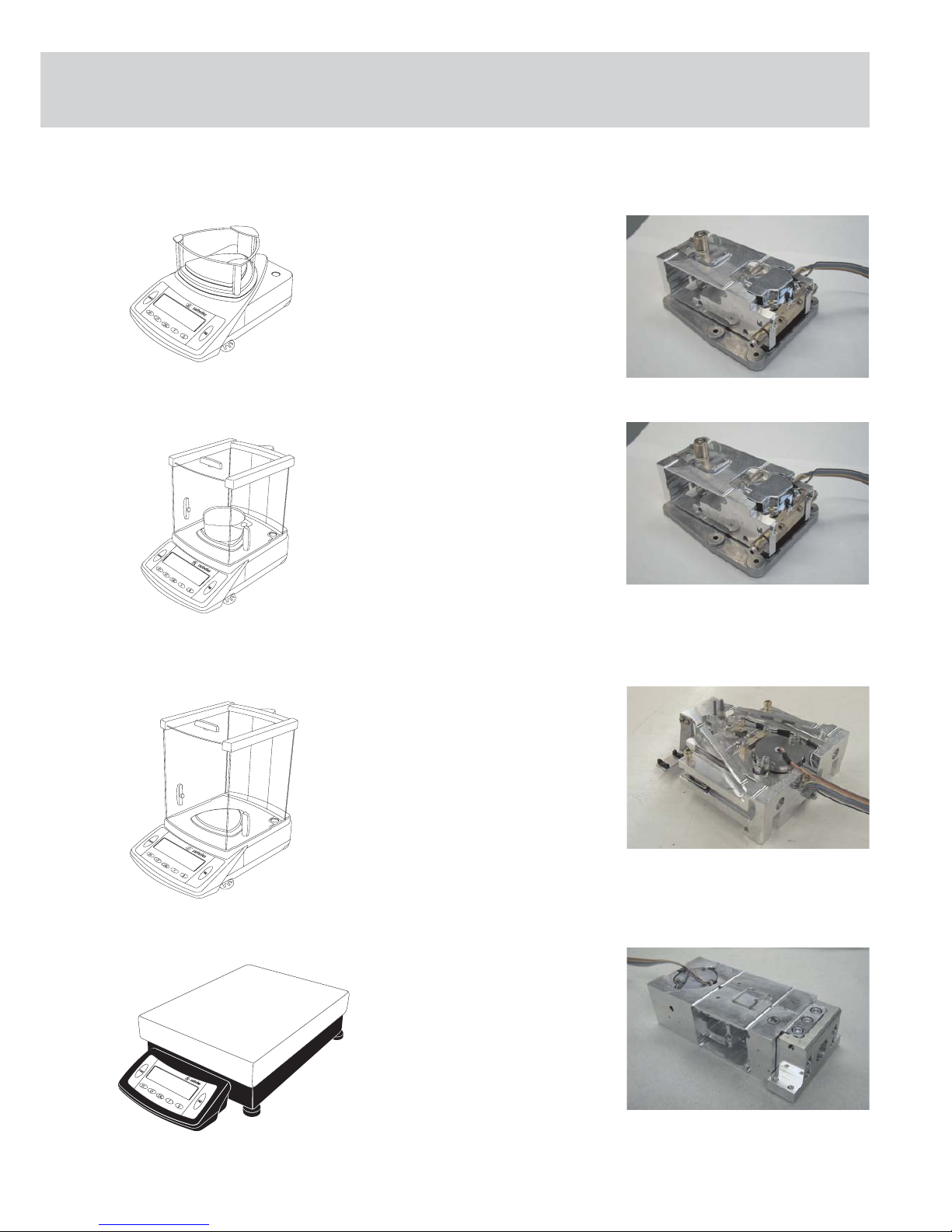
Handling and Operating the CP balances/scales
Function of the Keys
Position Description
1 Weighing unit
2 Taring
3 Pictograph for „GLP-compliant print-out active“
4 Pictograph for „Printing active“
5 Display: occupied memory in the net total applications
program
6 Data output (Print)
7 Function key:
activates selected applications program
8 Pictograms for the selected application
9 Activate calibration/adjustment mode
1*
2*
3*
4*
5*
710
11
12
13
15
2*
6*
14
Position Description
10 Clear Function
This key is used as an abort key:
- Deactivate applications program
- Interrupt calibration/adjustment mode
11 ON/OFF key:
Shuts the display on and off.
(The balance/scale may remain on -
depending on the factory setting.)
12 Display: Calibration/adjustment mode
13 Display: animal weighing with automatic start
14 Pictograph for stand-by operations or zero range
15 Weight display depending on the
selected basic unit
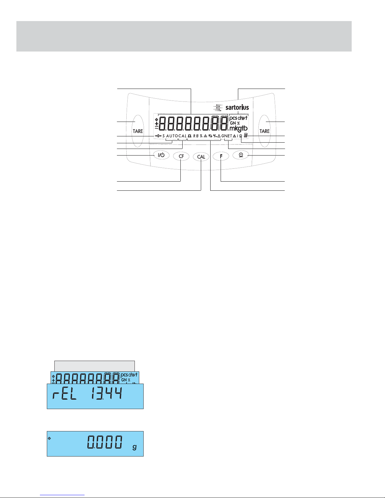
Displaying the Hardware and Software Versions
- Turn the balance/scale on and back off again with the e button.
- While all display segments are lit („Segment Test“), briefly press the p key,
the pattern shown to the left appears in the display.
- This remains displayed for around 3 sec.
- The first number shows the hardware generation; the last two numbers the
software version.
- The display then returns to the normal weight readout mode.
Anz_07-F.eps
Anz_00-F.eps
8
9
Page 10
10 |
Funktion Service-Switch
Aut_4106.ipg / CP_bpi_sch.eps
Aut_4106.ipg / CP_bpi_t_sch.eps
2
2
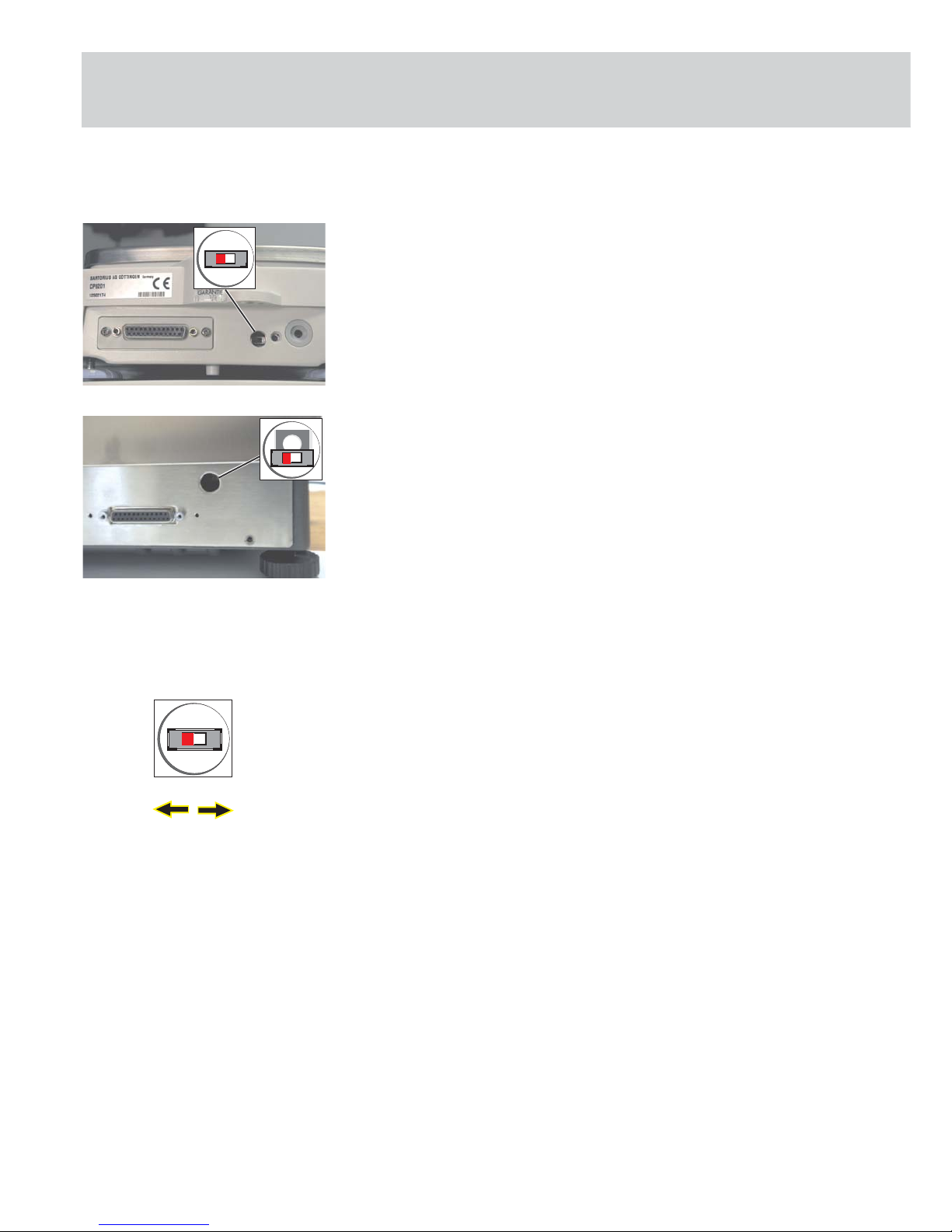
Access Lock Switch
The access lock switch (2) is located on the rear panel of the balance/scale.
On models CP622, CP4202S, CP3202S, CP3202P, CP2202S, GP5202, GP3202, CP8201,
CP6201, CP4201, CP2201, GP8201, CP423S, CP323S, CP323P, CP153, GC2502,
CP225D, CP324S, CP224S, CP124S, CP64, GC1603, GC803S, GC803P, the opening on
the left is intended for the access lock switch (2) (see fi gure on the left).
With the CP225D it´s in an external electronics box
On models CP34001S, CP34001P, CP34000, CP16001S, CP12001S, the opening on
the left is intended for the access lock switch (2) (see fi gure on the left).
Caution! Always leave the access lock switch (see left) in its left position. This switch
should only be operated on models verifi ed for use in legal metrology!
Depending on the model (verifi able or standard), the switch has two functions.
1. To unlock the menu to change the menu code settings „ 1 9 2 „ the external
span adjustment on verifiable balances/scales.
External adjustments are generally possible on standard models. It is not neces-
sary to open or close the switch.
2. After the menu is activated „ 8 1 2 „ (read only parameter), it can be released
by moving the switch (2) read only (right position) or for changing the settings
(left position).
Note: On verifi ed models, span adjustment can be carried out with external weights
without the service software.
Procedure:
1. Open access lock switch
2. Activate menu „ 1 9 7 „
3. Press the q key
4. Adjust the balance/scale
5. Close access lock switch!!
Right
closed
Left
open
Page 11
| 11
Accessing and Setting the Balance Operating Menu
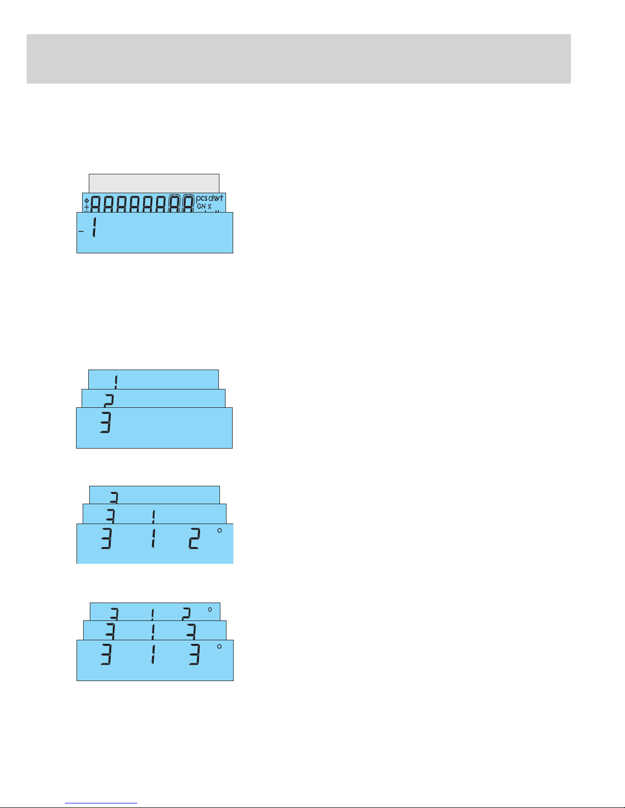
Accessing the Menu Using the „e“ „t“ keys:
- Turn the balance/scale off and back on by pressing the e button.
- While all segments are displayed (Segment Test), briefly press t.
- „1“ is displayed.
Note:
If „ -1“ is displayed, this indicates that the operating menu is blocked by the menu
access switch (see fi gure on the left). Menu code setting „ 8 1 2 „ (read only
parameters) is activated.
To unlock the menu to change the menu code settings, move the menu access
switch to the left.
Move the switch back to the right after you have made your changes!
Selecting a Menu Code Setting Using the „q“ and „p“ Keys:
- Press q to select the desired number. Numbers increase by one each time
they are pressed and go from 9 back to 1 again (1, 2, 3 ... 8, 9, 1 ...).
- Press p to move from the first code number to the second and third numbers
(1st - 2nd - 3rd etc.). Numbers increase by one each time they are pressed and go
from 3 back to 1 again (1st - 2nd - 3rd - 1st etc.).
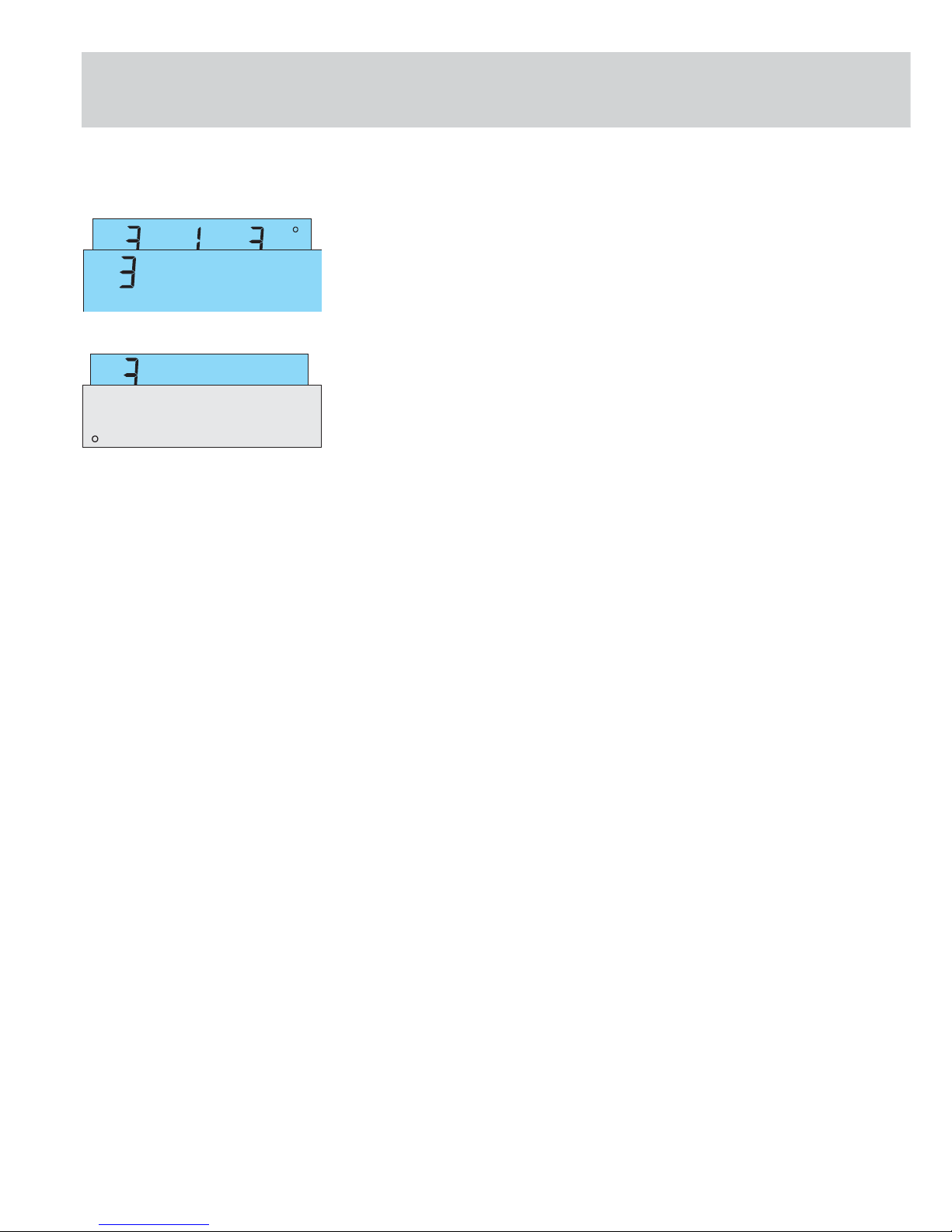
Changing and Storing a Setting with the „t“ Key:
- Briefly press one of the t keys to confirm desired setting. A „°“ appears after
the new setting, e.g. „3-1-3 °.“
- To store the setting, press one of the t keys for more than two seconds.
Anz_01-F.eps
Anz_02-F.eps
Balance Operating Menu
Anz_04-F.eps
Anz_03-F.eps
Page 12
12 |
Anz_05-F.eps
Anz_06-F.eps
Exiting the Menu Without Storing:
- To exit the menu, press p. This returns you to the first position in the
balance/scale operating menu.
- If you do not wish to store the changes, press the t key to deactivate this
menu item during the selection procedure or before storing by pressing e
(balance/scale is switched off).
Page 13

| 13
1 11 Weight Unit for Calibration Weight *
1 11 1 o Grams
1 11 2 Kilograms
1 11 3 Pounds
Menu 2 Application Programs
2 1 Program selection
2 1 1 o Weighing as the basic function
2 1 2 Toggle weight units (mass unit
conversion)
2 1 4 Counting
2 1 5 Weighing in percent
2 1 6 Net total formulation
2 1 7 Animal weighing / Averaging
Menu 3 Application Parameters
3 1 2nd Weight Unit
3 1 1 Grams (Display: o)*
3 1 2 o Grams (Display: g)
3 1 3 Kilograms
3 1 4 Carats
3 1 5 Pounds*
3 1 6 Ounces*
3 1 7 Troy ounces*
3 1 8 Hong Kong taels*
3 1 9 Singapore taels*
3 1 10 Taiwanese taels*
3 1 11 Grains*
3 1 12 Pennyweights*
3 1 13 Milligrams
3 1 14 Parts per pound*
3 1 15 Chinese taels*
3 1 16 Mommes*
3 1 17 Austrian carats*
3 1 18 Tola*
3 1 19 Baht*
3 1 20 Mesghal*
3 2 Range 2 Display Mode *
3 2 1 o All digits
3 2 5 Reduced by 1 digit
3 5 Resolution for Counting and Weighing in
Percent
3 5 1 Display accuracy (internal resolu
tion)
3 5 2 o Full accuracy
3 6 Decimal Places for Calculations
3 6 1 None
3 6 2 o Without one decimal place
3 6 3 Without two decimal places
3 6 4 Without three decimal places
3 7 Animal Actvity for Delaying Start until:
3 7 1 Stable conditions (calm)
3 7 2 o Normal
3 7 3 Unstable conditions (active)
3 8 Animal Weighing Will Start by
3 8 1 Manual mode
3 8 2 o Automatic mode
Menu 1 Weighing
1 1 Filter Selection
1 1 1 Very stable conditions
1 1 2 o Stable conditions
1 1 3 Unstable conditions
1 1 4 Very unstable conditions
1 2 Applications Filter
1 2 1 o Standard weighing mode
1 2 2 Manual fi lling mode
1 3 Stability Range
1 3 1 1/4 digit
1 3 2 1/2 digit
1 3 3 1 digit
1 3 4 o 2 digits
1 3 5 4 digits
1 3 6 8 digits*
1 5 Tare Parameter*
1 5 1 At any time
1 5 2 o Not until readout is stable
1 6 Auto Zero Function
1 6 1 o Auto Zero on
1 6 2 Auto Zero off
1 7 1st Weight Unit
1 7 1 Grams (Display: o)*
1 7 2 o Grams (Display: g)
1 7 3 Kilograms
1 7 4 Carats
1 7 5 Pounds*
1 7 6 Ounces*
1 7 7 Troy ounces*
1 7 8 Hong Kong taels*
1 7 9 Singapore taels*
1 7 10 Taiwanese taels*
1 7 11 Grains*
1 7 12 Pennyweights*
1 7 13 Milligrams
1 7 14 Parts per pound*
1 7 15 Chinese taels*
1 7 16 Momme*
1 7 17 Austrian carats*
1 7 18 Tola*
1 7 19 Baht*
1 7 20 Mesghal*
1 8 Range 1 Display Mode*
1 8 1 o All digits
1 8 5 Reduced by 1 digit*
1 9 q Calibration /Adjustment Function
1 9 1 o External calibration/adjustment
1
)
1 9 3 Internal calibration/adjustment 3)
1 9 5 External linearization 3)
1 9 6 Internal linearization/calibration 3)
1 9 7 q key blocked 4)
1 10 Calibration /Adjustment Sequence
1 10 1 o Calibrate, then auto adjust
1 10 2 Calibrate, then manual adjust
Menu Code Settings (Rel BAC 13.44 Version)
4)
If Access Switch is locked (otherwise extern Cal./adjustment)
Page 14

14 |
Menu 4 Application Parameters - Counting
4 1 Auto reference sample updating function
4 1 1 o Off
4 1 2 On
Menu 5 Data Interface
5 1 Baud rate
5 1 1 150 baud
5 1 2 300 baud
5 1 3 600 baud
5 1 4 o 1200 baud
5 1 5 2400 baud
5 1 6 4800 baud
5 1 7 9600 baud
5 1 8 19200 baud
5 2 Parity
5 2 1 Mark
5 2 2 Space
5 2 3 o Odd
5 2 4 Even
5 3 Number of Stop Bits
5 3 1 o 1 stop bit
5 3 2 2 stop bits
5 4 Handshake Mode
5 4 1 Software handshake
5 4 2 o Hardware handshake,
2 char. after CTS
5 4 3 Hardware handshake,
1 char. after CTS
Menu 6 Utilities for Printouts/ Basic Function Weig
hing
6 1 Manual/Auto print
6 1 1 Manual with p key
without stability
6 1 2 o Manual with p key
after stability
6 1 3 Manual with p key
at stability
6 1 4 Auto print without stability
6 1 5 Auto print at stability
6 1 6 Auto print when load changes 2)
6 2 Automatic Printing
6 2 1 Start/stop auto print using the
p key
6 2 2 o Auto print not stoppable
6 3 Time-Dependent Printouts at Defi ned Inter
vals
6 3 1 o 1 display update
6 3 2 2 display update
6 4 Automatic Taring after Each Printout
6 4 1 o Off
6 4 2 On
Menu 7 Print Application Programs
7 1 Print Application Parameter
7 1 1 Off
7 1 2 o On; all param.
7 1 3 On; only main parameters
7 2 Print Format
7 2 1 Raw data (16 char.)
7 2 2 o For other apps
(22 char.)
7 3 Auto Print Net Total Formulation / 2nd
Tare Memory
7 3 1 o Auto print last value N1
7 3 2 Auto print total T1
Menu 8 Extra Functions
8 1 Menu Access Function *
8 1 1 o Parameter settings alterable
8 1 2 Read only
8 2 Acoustic signal
8 2 1 o On
8 2 2 Off
8 3 Key Functions
8 3 1 o Accessible
8 3 2 Blocked
8 4 Universal Switch for Remote Control
8 4 1 o p
8 4 2 t
8 4 3 q
8 4 4 v
8 4 5 c
8 5 Power-On Mode
8 5 1 o Off/on/Stand-by
8 5 3 Stand-by/on
8 5 4 Auto on
8 8 Reference Weighing for Counting Small
Parts
8 8 1 o Off
8 8 2 On for QC scale
8 8 3 On for FB/FC/LA/LP scales
8 8 4 On for isi terminal
8 10 ISO/GLP-compliant Printout
8 10 1 o No ISO/GLP-compliant printout
8 10 2 Only for calibration/adjustment
8 10 3 Always on - all printouts
ISO/GLP-compliant
Menu 9 Reset Menu to Factory Settings
9 - 1 Restore
9 - 2 o Do not restore
Also resets SBI mode
Caution: Before resetting the menu, note down the menu settings
* = Not used for on balances/scales verifi ed for legal metrology.
1) = Not possible on balances/scales of accuracy class K verifi ed for legal
metrology
2) = Auto print, when weight changes > 10 d and
Stability: menu access switch < 5 d
3) = Only on models with internal r weight switch
o) = Model-dependent factory setting
Page 15
| 15
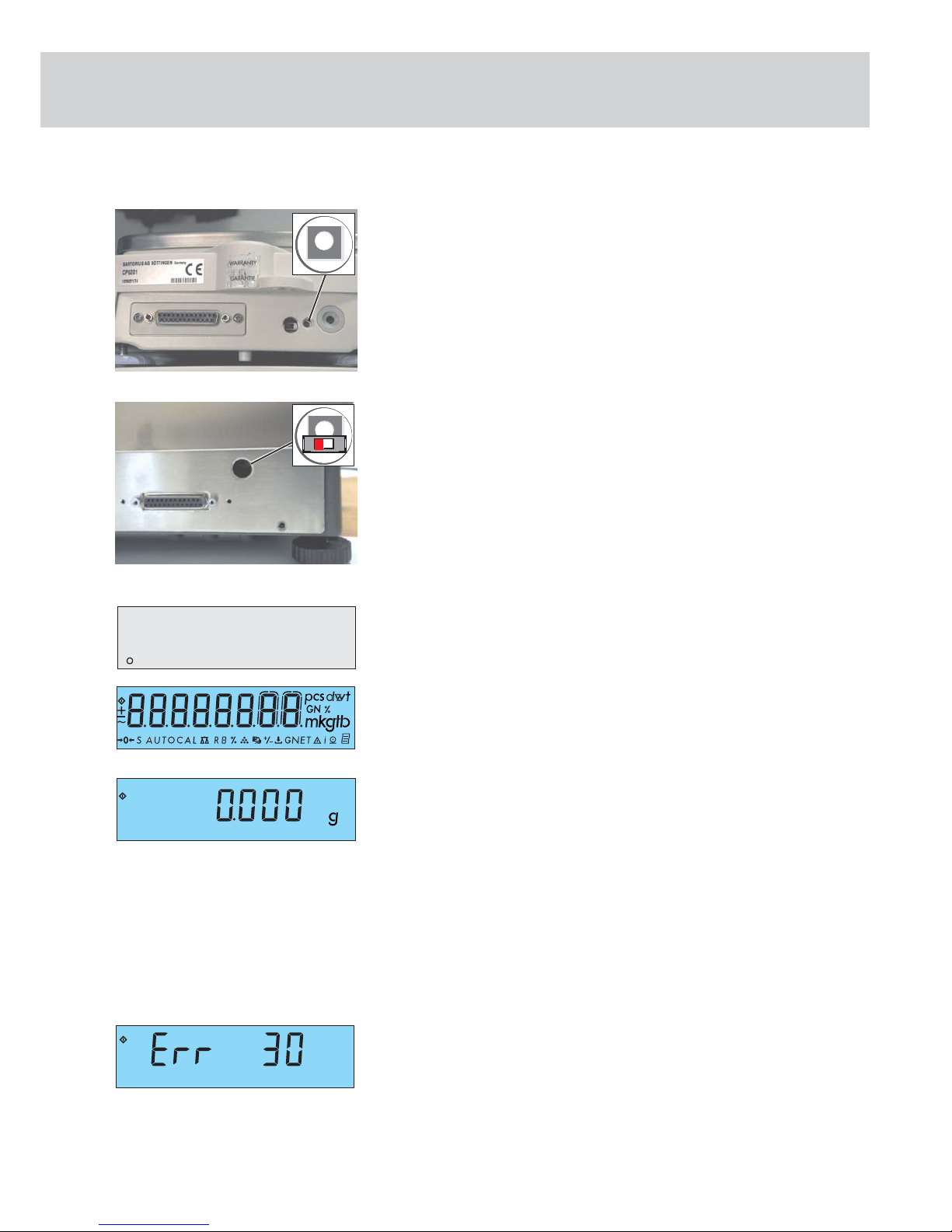
Activating the BPI Mode
The BPI switch (1) is used to prepare for working the service software and is located
on the rear panel.
On models CP622, CP4202S, CP3202S, CP3202P, CP2202S, GP5202, GP3202, CP8201,
CP6201, CP4201, CP2201, GP8201, CP423S, CP323S, CP323P, CP153, GC2502,
CP225D, CP324S, CP224S, CP124S, CP64, GC1603, GC803S, GC803P, the middle
opening is intended for the BPI switch (1) (see fi gure left).
With the CP225D it´s in an external electronics box
On models CP34001S, CP34001P, CP34000, CP16001S, CP12001S, on opening is
intended for the BPI switch (1) (see fi gure left).
Note:
To use the CAS programs (Version 1.44 and later) or the SARTORIUS MC1 Server
(version 4.9 and later and later), the balance/scale must be set to the BPI mode (=
Binary Processor Interface Mode) (e.g. for linearization /span adjustment or when
replacing the PCB).
- Turn on the balance/scale using the e key and wait for the segment test on the
balance/scale to run, i.e. until (e.g. CP423S) „ 0.000 g „ is displayed.
- Remove the capped plug from the rear panel of the balance, located to the left
of the DC jack (screw).
- The BPI switch is now accessible through the opening. Press the BPI switch once,
e.g. with a ball-point pen and hold it in:
- The weight readout in the display disappears (8-er-check it is executed).
- After about 3 seconds, the interface will be in the BPI mode.
- Release the BPI switch, the balance/scale now returns automatically to the
normal weight readout mode, but is still in the BPI Mode.
(Only SARTOCAS is functional).
- Insert the plug to close the opening on the back panel of the balance/scale.
- You can now use the balance/scale together with the SARTOCAS program
(version 1.44 and later) for PCs or the Psion server (version 4.9 and later) in
the BPI Mode.
Caution! After working in the BPI Mode, make sure to set the write-protect (with the
SARTOCAS program for SARTORIUS MC1 Server (Version 4.9 and later)), so that
the balance/scale returns to the standard data record output mode (SBI mode =
Sartorius Balance Interface).
If the balance/scale is in the BPI Mode (= Binary Processor Interface Mode) when you
press p key, the error code ERR 30 will be displayed!
You cannot run the standard peripheral devices until you set the balance/scale back
to the SBI mode!
Note: If necessary, it is possible to switch from SBI to BPI by activating the menu setting
»9 - 1« (menu reset).
Anz_00-F.eps
Anz_88-F.eps
Anz_OFF.eps
Aut_4106.ipg / CP_bpi_t.eps
Aut_4106.ipg / CP_bpi_t_sch.eps
1
1
Function Service BPI Switch
Anz_err30-F.eps
Page 16

16 |
B
A
Waagenplatte.tif
Überlast.tif
Testing and Adjustment Sequence on Balances/Scales with
Strain Gauge Systems
Preparations: Place the balance/scale on a solid, level surface that is free of vibration, e.g.
a stone table. Level the balance/scale using the level indicator. Turn the balance/
scale and allow it to warm up for about 30-60 minutes, depending on the model.
Calibrate/adjust the balance/scale on this place.
Note: Testing must be carried out according to the following Sartorius Standard Operating
Procedure for Testing WKD-037-02 and WKD-038-02. They are also equivalent to the
given adjustment data as described in this service manual.
You will need to check and, if necessary, adjust the following:
1. Overload stop
2. Zero point offset adjustment
3. Repeatability
4. Off-center loading error
5. Span adjustment
6. External linearity
Checking the Overload Stop
Note: Overload stops only need to be checked after replacing a strain gauge system.
Setting the Overload Stop
Setting the overload stops is only necessary in the case of mechanical damage or
after replacing the load cell!
After opening the balance/scale , screw off the load plate and remove it from the
weighing system.
If there is only one load plate, the two screws (A) have to be removed to obtain
access to the strain gauge.
Adjust the two overload stop screws (B) so that a distance of about 0.1 mm (paperthick) remains between the screws and the base plate when the maximum load plus
around 10% is placed on the balance/scale.
Caution: The overload stop screws (B) are not lock nuts. If ERR 02/03 appears during
adjustment work, make that the overload stop screws are at the proper setting.
Testing and Adjustment Sequence on Balances/Scales with Strain Gauge Systems
Page 17

| 17
The offset adjustment adapts the weighing system to the internal A/D converter.
You may need to adapt the A/D converter:
- after replacing the strain gauge measuring spring
- after replacing the main PCB
- when the sensitivity of the balance/scale cannot be adjusted (not even using the
service software) and error code „Err 02“ is displayed.
There are two ways of adapting the converter:
1. with a digital voltmeter
2. using the service software (SARTOCAS, PSION Server)
1. Adapting the A/D Converter using a Digital Voltmeter:
- Open balance/scale
- Reconnect balance/scale to mains power
- Unload the weighing pan, use a digital voltmeter to measure IC6 Pin 6 against
GND (see figure on the left)
Open the solder bridges and measure the ground at IC6 Pin 6. Depending on the
voltage displayed, open or close the solder bridges in accordance with the chart (see
next page). If the adjustment cannot be carried out through the solder bridges, an
adjustment resistance (R, see fi gure left) determined with a decade resistor can be set
when the solder bridges of the offset are open.
Caution! The converter output must be within the range of the between
-250 mV and -650 mV!
After replacing the main PCB, it may be necessary to transfer the existing
adjustment resistance (R) to the new PCB.
Umeas (V) J1 J2 J3
(solder bridges are open)
-0.212...+0.153 Closed Open Open
+0.153...+0.518 Open Closed Open
+0.518...+0.883 Closed Open Closed
+0.883...+1.249 Closed Closed Closed
2. Adapting the A/D Converter Using the Service Software (SARTOCAS /PSION):
- Activate the BPI Mode
- Use the service software in the „Diagnosis“ menu to check the output level
(modulation) of the A/D converter
Caution!
Opening or closing solder bridges (J1 - J3) must change the converter output to
within the range of 5% to 14%!
J3
J2
J1
R
Aut_5027.jpg
IC6 Pin6
GND
Aut_5027.jpg
R
Zero point offset adjustment
Page 18

18 |
Checking the Repeatability (Standard deviation)
- Select the test weight from the „Calibration/Adjustment Data Sheet“ (see pages
42-43).
- Unload the weighing pan and zero the balance/scale using the t key.
- Center the test weight on the weighing pan.
- Write down the weight displayed.
- Repeat the procedure five times.
- The repeatability is calculated from the 6 weighing operations as follows:
(Max. value displayed - Min. value displayed) / 3
- Compare the calculated value with the given tolerance.
- If the calculated value is not within the given tolerance, it may be due to one
of the following reasons:
- The weighing system needs to be cleaned
- Mechanical parts are in the weighing system
- Bent / defective bending elements
Checking and Adjusting the Off-Center Loading Error
Caution: Larger errors in the off-center loading error affect the repeatability of the
weighing system!
The OIML Guideline R76-1 describes the tests for off-center loading tolerances for
square, round and even triangular weighing pans. Therefore, the test weight should
be placed on every 1/4 of the weighing pan surface.
The positions for placing test weights in triangular weighing pans are indicated in
the fi gures to the left.
Please refer to the sketches to the left to establish the testing points for checking
the off-center loading tolerances.
The markings should help you place the test weights in their proper positions.
Checking the Off-Center Loading Tolerances
Note: Select the test weights from the „Calibration/Adjustment Data Sheet (see
pages 42-43).
CP Balances/Scales with Rectangular Weighing Pans
Models: CP622
- Place the test weight on position 1 on the weighing pan and zero the balance/
scale by pressing the t key.
- In the order given, place the test weight in the position 2, 3, 4 and 5 as indicated
and write down the readout at stability, including the plus/minus signs.
- If the off-center loading error is too large, adjust the balance so that the offcenter loading error is within the tolerances specified.
CP Balances/Scales with Square Weighing Pans
Models: CP8201, CP6201, CP4201, CP2201, GP8201
- Compare the test weights with the tolerances listed in the „Calibration/
Adjustment Data Sheet (see pages 42-43).
- If the off-center loading error is too large, adjust the balance so that the offcenter loading error is within the tolerances specified.
Eck_re_1.eps
Eck_dr_2.eps
Front
5
2
1
3
4
Front
Eck_re_3.eps
Eck_dr_3.eps
Front
Front
5
2
1
4
3
Repeatability / Off-Center Loading
Page 19

| 19
Procedure for Adjusting the Off-Center Loading Error (Strain Gauge)
Note: After calibration/adjustment of the off-center loading error, you must check the
span and linearity and adjust as required.
On models CP2201, CP4201, CP6201, CP8201, GP8201, the off-center loading error
should be adjusted by careful fi ling at appropriately thin places.
First, remove the weighing support. On subsequent models, this adjustment can be
carried out through the long holes in the weighing pan support with an angled
round fi le. It is then no longer necessary to remove the weighing pan support.
- Carry out the adjustment by careful filing at the positions described.
- Only file negative errors, preferably at the upper thin sites
- To avoid distorting the adjustment results on models with a higher resolution
(60000 - 75000 increments), wait a few seconds after filing so that the thin
sites can „cool down.“
- After each adjustment, recheck the off-center loading error, as the force parallelogram of the measuring spring will also change the error in the non-adjusted
corners
- Check the off-center loading error once more after a longer period of time
1. Adjusting the Off-Center Loading Error: Front - Back
Negative error in the front:
(Captions: Weighing pan, right, left, front, back)
- File the edges of the upper thin site evenly on the left and right, moving inwards.
Small, inwardly tapering surfaces areas will be produced at the thin site „A“
Negative error in the back:
- File the edges of the upper thin site evenly on the left and right, moving inwards.
Small, inwardly tapering surfaces areas will be produced at the thin site „B“
back
right
loadplate
front
left
dms3ae.eps
dms3be.eps
A
B
back
right
loadplate
left
front
Page 20

20 |
back
right
loadplate
front
left
back
right
loadplate
front
left
2. Adjusting the Off-Center Loading Error: Right - Left
Negative error on the right:
- File the edges of the upper thin sites evenly on the front and back, moving
inwards. Small, inwardly tapering surfaces areas will be produced at the thin
sites „C“
Negative error on the left:
- File the edges of the upper thin sites evenly on the front and/or back, moving
inwards. Small, inwardly tapering surfaces areas will be produced at the thin
sites „D“
dms3ce.eps
dms3de.eps
D
C
Page 21

| 21
External Adjustment
Note: Before carrying out calibration/adjustment work, allow the balance/scale
to warm up (between 30 min. and 24h, depending on the model)!
The external calibration/adjustment can be performed in various ways.
Only use calibrated weights!
1. As described in this manual
2. or using the Sartorius MC1 Server (version 4.9 or later) or the SARTOCAS
program for PCs and laptops).
- Make sure that the balance/scale operating menu is set to the code „1 9 1 external calibration/adjustment accessible“ (see pages 13-14 „Operating Menu
Settings“) or „1 9 7 - external adjustment/calibration/", the Access Lock Switch
has to be closed.
- If necessary, tare the balance/scale by pressing the t key. Press q to
activate the calibration/adjustment routine.
- The calibration weight required is displayed, (depending on the model, e.g.
CP4201).
Caution! The balance/scale only accepts a weight that is within a tolerance range of
approx. 2% of the nominal value. Errors exceeding this tolerance range can only
be corrected using the SARTORIUS MC1 Server Software.
- Center the required weight (e.g. 2000g/F2) on the weighing pan and close the
draft shield.
- After the calibration weight has been stored, the balance will return to the
weighing mode.
– Menu »1 10 2 Calibration/Adjustment« calibration weight value will be displayed
first, then press q key.
Anz_14-F.eps
Anz_25-F.eps
Anz_26-F.eps
Waags_Just.eps
Front
Span adjustment
Page 22

22 |
Adjusting External Linearity
Checking the Linearity
Note: The linearity must be checked according to the Standard Operating Procedure
WKD-038.
- Check the linearity of the balance/scale for the entire weighing range in 4-g
steps.
- Compare the values displayed with the tolerance ranges given in the „Table of
Calibration/Adjustment Data“ on pages 42-43.
- If the errors exceed the permissible tolerance ranges, the linearity must be
adjusted.
Adjusting the Linearity
Caution! You can adjust the linearity on CP balances/scales only using the SARTORIUS MC1
Server Software (Version 4.9 and later) or with the SARTOCAS program.
- Activate the BPI mode (see page 15).
- Adjust the linearity with the SARTORIUS MC1 Server (version 4.9 and later) or
with the SARTOCAS program for PCs and laptops.
(Please see the program description for instructions on this automatic proce-
dure!).
Adjusting Linearity
Page 23

| 23
Testing and Adjustment Sequence on Balances/Scales with Double
Lever Systems
Preparations: Place the balance/scale on a solid, level surface that is free of vibration, e.g.
a stone table. Level the balance/scale using the level indicator. Turn the balance/
scale and allow it to warm up for about 30-60 minutes, depending on the model.
Calibrate/adjust the balance/scale on this place.
Note: Testing must be carried out according to the following Sartorius Standard Operating
Procedure for Testing WKD-037-02 and WKD-038-02. They are also the equivalent of
the given adjustment data as described in this service manual.
You will need to check and, if necessary, adjust the following:
1. Overload stop
2. Repeatability
3. Off-center loading error
4. Span adjustment
5. External linearity
Checking the Overload Stop
Note: Overload stops no longer need to be checked on double lever systems.
Setting the Overload Stop
It is no longer necessary to set the overload stops. They are factory set and adjusted.
Checking the Repeatability (Standard deviation)
- Select the test weight from the „Adjustment Datasheet (see Page 42-43).
- Unload the weighing pan and zero the balance/scale using the t key.
- Center the test weight on the weighing pan.
- Write down the weight displayed.
- Repeat the procedure five times.
- The repeatability is calculated from the 6 weighing operations as follows:
(Max. value displayed - Min. value displayed) / 3
- Compare the calculated value with the given tolerance.
- If the calculated value is not within the given tolerance, it may be due to one
of the following reasons:
- The weighing system needs to be cleaned
- Mechanical parts are in the weighing system
- Bent / defective bending elements
Testing and Adjustment Sequence on Balances/Scales with Double Lever
Eck_re_3.eps
Eck_dr_3.eps
Front
Front
Page 24

24 |
Checking and Adjusting the Off-Center Loading Error
Caution: Larger errors in the off-center loading error affect the repeatability of the
weighing system!
The OIML Guideline R76-1 describes the tests for off-center loading tolerances for
square, round and even triangular weighing pans. Therefore, the test weight should
be placed on every 1/4 of the weighing pan surface.
The positions for placing test weights in triangular weighing pans are indicated in
the fi gures to the left.
Please refer to the sketches to the left to establish the testing points for checking
the off-center loading tolerances.
The markings should help you place the test weights in their proper positions.
Checking the Off-Center Loading Tolerances
Note: The data for the test weight and the tolerance are listed in the „Adjustment
Datasheet (see Page 42-43).
CP Balances/Scales with Draft Shields and Triangular Weighing Pans
Models: CP423S, CP323S, CP323P, CP153, GC2502
- Place the test weight on position 1 on the weighing pan and zero the balance/
scale by pressing the t key.
- In the order given, place the test weight in the position 2, 3, 4 and 5 as indicated
and write down the readout at stability, including the plus/minus signs.
- If the off-center loading error is too large, adjust the balance so that the offcenter loading error is within the tolerances specified.
CP Balances/Scales with Square Weighing Pan
Models: CP4202S, CP3202S, CP3202P, CP2202S, CP5202, GP3202
- Compare the off-center loading errors with the tolerances listed in the („Adjustment Datasheet“ see Page 42-43).
- If the off-center loading error is too large, adjust the balance so that the offcenter loading error is within the tolerances specified.
5
2
1
4
3
Eck_re_2.eps
Eck_dr_wh1.eps
Front
5
2
1
3
4
Front
Checking Off-Center Loading
Page 25

| 25
Procedure for Adjusting the Off-Center Loading Error (Double Lever System)
Note: After calibration/adjustment of the off-center loading error, you must check the span
and linearity and adjust as required.
On models CP4202S, CP3202S, CP3202P, CP2202S, GP5202, GP3202,
CP153, CP323S, CP323P, CP423S, GC2502, the off-center loading error should be
adjusted by careful fi ling at appropriately thin places on the upper guide. To avoid
distorting the adjustment, wait a few seconds after fi ling so that the thin sites can
„cool down“.
Caution! After carefully removing the housing, adjust the off-center loading error only at
the thin sites in the back using an angled fi le.
Check the off-center loading error and adjust the largest error fi rst by carefully
fi ling at these points (see fi gures on the left and below).
The errors measured (see the section „Off-Center Loading Error) refer to the position
of the systems in the balance/scale.
Position of the Systems in the Balance/Scale
Off-center loading error:
Back-Left-Top Back-Left-Bottom Back-Right-Bottom Back-Right-Top
Filing positions: Filing positions: Filing positions: Filing positions:
Back-Right- Back-Right Back-Right-Top Back-Right-Bottom
and and or or
Left-Top Left-Bottom Back-Left-Bottom Back-Left-Top
Top
Bottem
Back
Front
Side view of the system
CP1d.tif
winkh.tif
CP_ecklj1.tif
CP_ecklj2.tif
front view
Adjusting Off-Center Loading
front view
front view
Page 26

26 |
Anz_14-F.eps
Anz_27-F.eps
Anz_28-F.eps
Span Adjustment
Waags_Just.eps
Front
External Adjustment
Note: Before carrying out calibration/adjustment work, allow the balance/scale to warm
up properly!
The external calibration/adjustment can be performed in various ways.
Only use calibrated weights!
1. As described in this manual,
2. or using the Sartorius MC1 Server (Version 4.4) or later) or the SARTOCAS
program for PCs and laptops).
- Make sure that the balance/scale operating menu is set to the code „1 9 1 e external calibration/adjustment accessible“ (see Page 13-14 „ Operating Menu
Settings“) or „1 9 7 - external adjustment/calibration/", the Access Lock Switch
has to be closed.
- If necessary, tare the balance/scale by pressing the t key. Press q to
activate the calibration/adjustment routine.
- The calibration weight required is displayed, (depending on the model, e.g.
CP4202S).
Caution! The balance/scale only accepts a weight that is within a tolerance range of
approx. 2% of the nominal value. Errors exceeding this tolerance range can only
be corrected using the SARTORIUS MC1 Server Software.
CP Balances/Scales with Draft Shields and Triangular Weighing Pans
Models: CP423S, CP323S, CP323P, CP153, GC2502
- Center the required weight (e.g. 200g/E2 depending on the model, e.g. CP423S)
on the weighing pan and close the draft shield.
- After the calibration weight has been stored, the balance will return to the
weighing mode.
– Menu »1 10 2 Calibration/Adjustment« calibration weight value will be displayed
first, then press q key.
CP Balances/Scales with Square Weighing Pan
Models: CP4202S, CP3202S, CP3202P, CP2202S, CP5202, GP3202
- Center the required weight (e.g. 2000g/E2 depending on the model, e.g.
CP4202S) on the weighing pan.
- After the calibration weight has been stored, the balance will return to the
weighing mode.
– Menu »1 10 2 Calibration/Adjustment« calibration weight value will be displayed
first, then press q key.
Eck_re_3.eps
Front
Page 27

| 27
Adjusting External Linearity
Checking the Linearity
Note: The linearity must be checked according to the Standard Operating Procedure
WKD-038.
- Check the linearity of the balance/scale for the entire weighing range in 4-g
steps.
- Compare the values displayed with the tolerance ranges given in the „Table of
Adjustment Data“ Page 42-43.
- If the errors exceed the permissible tolerance ranges, the linearity must be
adjusted.
Adjusting the Linearity
Caution! You can adjust the linearity on CP balances/scales only using the SARTORIUS MC1
Server Software (Version 4.9 and later) or with the SARTOCAS program.
- Activate the BPI mode (see Page 15).
- Adjust the linearity with the SARTORIUS MC1 Server (Version 4.9 and later) or
with the SARTOCAS program for PCs and laptops.
(Please see the program description for instructions on this automatic proce-
dure!).
Adjusting Linearity
Page 28

28 |
Testing and Adjustment Sequence on Balances/Scales with Monolithic Weighing
Systems
Preparations: Place the analytical balance on a solid, level surface that is free of vibration,
e.g. a stone table. Level the analytical balance using the level indicator. Turn the
balance/scale and allow it to warm up for about 4h-24h.
Note: Testing must be carried out according to the following Sartorius Standard Operating
Procedure for Testing WKD-037-02 and WKD-038-02. They are also the equivalent of
the given adjustment data as described in this service manual.
You will need to check and, if necessary, adjust the following:
1. Overload stop
2. Repeatability
3. Off-center loading error
4. Span adjustment
External span adjustment
Overwrite internal calibration weight
Internal span adjustment
5. Linearity
External linearization
Overwrite internal linearity weight
Checking the Overload Stop
Note: Overload stops no longer need to be checked monolithic weigh cells.
Setting the Overload Stop
It is no longer necessary to set the overload stops. They are factory set and adjusted.
Checking the Repeatability (Standard deviation)
- Select the test weight from the „Adjustment Datasheet (see Page 42-43).
- Unload the weighing pan and zero the balance/scale using the t key.
- Center the test weight on the weighing pan.
- Write down the weight displayed.
- Repeat the procedure five times.
- The repeatability is calculated from the 6 weighing operations as follows:
(Max. value displayed - Min. value displayed) / 3
- Compare the calculated value with the given tolerance.
If the calculated value is not within the given tolerance, it may be due to one
of the following reasons:
- The weighing system needs to be cleaned
- Mechanical parts are in the weighing system
- Bent / defective bending elements
Waags_Just.eps
Front
Balances/Scales with Monolithic Weighingssystems
Page 29

| 29
Checking and Adjusting the Off-Center Loading Error
Caution: Larger errors in the off-center loading error affect the repeatability of the
weighing system!
The OIML Guideline R76-1 describes the tests for off-center loading tolerances for
square, round and even triangular weighing pans. Therefore, the test weight should
be placed on every 1/4 of the weighing pan surface.
The positions for placing test weights in triangular weighing pans are indicated in
the fi gures to the left.
Please refer to the sketches to the left to establish the testing points for checking
the off-center loading tolerances.
The markings should help you place the test weights in their proper positions.
Checking the Off-Center Loading Tolerances
Note: The data for the test weight and the tolerance are listed in the „Adjustment
Datasheet (see Page 42-43).
CP Semimicro-Balances with Rectangular Weighing Pans
Models: CP225D, CP324S, CP224S, CP124S, CP64, GC1603, GC803S, GC803P
- Place the test weight on position 1 on the weighing pan and zero the balance/
scale by pressing the t key.
- In the order given, place the test weight in the position 2, 3, 4 and 5 as indicated
and write down the readout at stability, including the plus/minus signs.
- If the off-center loading error is too large, adjust the balance so that the offcenter loading error is within the tolerances specified.
Adjusting the Off-Center Loading Error (Monolithic System)
Off-center loading errors are determined by carrying out a 3-point adjustment.
The 3-point adjustment shows the greatest possible off-center loading error on the
balance/scale.
Note: You have to open the balance/scale for calibration/adjustment of the off-center
loading error.
- Remove the weighing pan and draft shield ring
- Open the draft shield cover and carefully remove the draft shield
- Remove the Seal of Warranty on the back panel of the balance/scale and the
loosen the thumbscrew (K)
- First, move the top part of the balance/scale to the back and then carefully
lift upwards
- Replace the weighing pan
Note: In the future, two openings in the top part of the balance/scale will make it
unnecessary to remove the housing.
open
closes
K
winds.jpg
5
2
3
4
5
2
3
4
1
Eck_dr_mo3.eps
Checking the Off-Center Loading
Page 30

30 |
3-Point Adjustment
- During calibration/adjustment of the off-center loading error, the system must
be covered over.
- To adjust the off-center loading error, change the settings of the off-center
load thumbscrews.
- Place the test weight in position A on the weighing pan and zero the balance/
scale by pressing t.
- In the order given, place the test weight in the position B and C and write down
the readout at stability
- Example: Position A tkey 0.0000 g
Position B + 0.0005 g
Position C - 0.0004 g
- Only adjust the side with the greatest error (in the amount), taking into account:
Negative errors
Turn the off-center load thumbscrews inwards (clockwise)
Positive errors
Turn off-center load thumbscrews outwards (counterclockwise)
- Adjust the thumbscrew by small turns and then recheck the off-center loading
error at positions A-C
- Repeat this procedure until the off-center loading error is within 3 points of
the tolerance range.
Note: After adjusting the off-center loading error, you must also check and, if necessary,
adjust the linearity and span on the balance/scale.
Caution! During assembly, be careful not to damage the internal data cable!
- Insert the upper part of the balance/scale (tilting it slightly) so that the two
retainers (under the keypad) lock into the two screws (in the front part of the
bottom of balance/scale)
- Slide the upper part of the balance/scale carefully to the front and then push
down gently
- Fasten the housing by tightening screw (K) and affix the Seal of Warranty
- Open the draft shield cover
- Place the draft shield on the balance/scale, align by eye, press down on the draft
shield gently from above and close the cover
- Replace the draft shield ring and weighing pan
open
closes
K
winds.jpg
A
B
C
Eck_dr_mo2.eps
AUT_5201.jpg
Page 31

| 31
External Adjustment
Note: The external calibration/adjustment can be performed in various ways.
Only use calibrated weights!
1. As described in this manual,
2. or using the Sartorius MC1 Server (Version 4.9 or later) or the SARTOCAS
program for PCs and laptops).
- Make sure that the balance/scale operating menu is set to the code „1 9 1 external calibration/adjustment accessible“ (see pages 13-14 „Operating Menu
Settings“) or „1 9 7 - external adjustment/calibration/", the Access Lock Switch
has to be closed.
- If necessary, tare the balance/scale by pressing the t key. Press q to
activate the calibration/adjustment routine.
- The calibration weight required is displayed, (depending on the model, e.g.
CP225D).
Caution! The balance/scale only accepts a weight that is within a tolerance range of
approx. 2% of the nominal value. Errors exceeding this tolerance range can only
be corrected using the SARTORIUS MC1 Server Software.
- Center the required weight (e.g. 200g/E1) on the weighing pan and close the
draft shield.
- After the calibration weight has been stored, the balance will return to the
weighing mode.
– Menu »1 10 2 Calibration/Adjustment« calibration weight value will be displayed
first, then press q key.
Overwriting the Internal Calibration Weight
Caution! The internal calibration weight on CP balances/scales should only be overwritten
using the PSION Server or the SARTOCAS program for PCs and laptops, since the
factory setting of the internal calibration weight is highly accurate. Only in the
case of emergency (e.g. no service software available) should you perform the
overwrite protection using the balance‘s overwrite program).
Important: Before carrying out the overwriting internal calibration weight, you must cor-
rectly adjust the span.
The balance/scale must warm up for at least 4 - 24 hours!
Note: There are various ways of overwriting the internal calibration weight on CP balances/
scales.
1. As described in this manual
2. or using the Sartorius MC1 Server (Version 4.9 or later) or the SARTOCAS
program for PCs and laptops).
Anz_14-F.eps
Anz_15-F.eps
Anz_16-F.eps
Waags_Just.eps
Front
Span Adjustment
Page 32

32 |
- Make sure that the balance/scale operating menu is set to the code „1 9 3 internal calibration/adjustment accessible „ (see Page 13-14 „ Operating Menu
Settings „).
- Slide the access lock switch to the left. It is accessible via an opening on the
back of the balance/scale.
- If you have done so already, perform external calibration/adjustment (see Page
31).
- Turn off the balance/scale by pressing e.
- Turn the balance/scale back on by pressing e and while simultaneously
holding down the q key until the readout shown on the left appears.
- Press the t key to tare the balance/scale; then press q to activate the
„overwrite internal calibration weight“ function.
- The built-in, motorized internal calibration weight is applied, then removed
automatically; the weight value is overwritten; and the balance/scale returns to
the normal weighing mode.
- Press the q key to check the external span adjustment once again.
Internal Span Adjustment
- Make sure that the menu code „1 9 3 - internal calibration/adjustment accessible“ is set (see Page 13 -14 Operating Menu Settings).
- Press the t key to tare the balance/scale; then press q to activate the
calibration/adjustment function..
- The built-in, motorized internal calibration weight is applied, then removed
automatically; the weight value is overwritten; and the balance/scale returns to
the normal weighing mode.
- Slide the access lock switch back to the right. Replace the capped plug to close
the opening.
Anz_09-F.eps
Anz_10-F.eps
Left
open
Right
closed
CP_bpi_sch.eps
Anz_19-F.eps
Anz_20-F.eps
Anz_09-F.eps
Anz_19-F.eps
Anz_20-F.eps
right
closed
CP_bpi_sch.eps
Page 33

| 33
Linearity
Checking the Linearity
Note: The linearity must be checked according to the Standard Operating Procedure
WKD-038.
- Check the linearity of the balance/scale for the entire weighing range in 50-g
steps.
- Compare the values displayed with the tolerance ranges given in the „Table of
Calibration/Adjustment Data“ on pages 42-43.
- If the errors exceed the permissible tolerance ranges, the linearity must be
adjusted.
Adjusting the Linearity
Caution! You can adjust the linearity on CP balances/scales only using the SARTORIUS MC1
Server Software (Version 4.9 and later) or with the SARTOCAS program.
- Activate the BPI mode (see page 15).
- Adjust the linearity with the SARTORIUS MC1 Server (Version 4.9 and later) or
with the SARTOCAS program (Version 1.44 or later) for PCs and laptops.
(Please see the program description for instructions on this procedure!).
Alternative manual procedure:
- When using the operating menu, make sure that the code „1 9 5 -external
linearization accessible“ is set (refer to page 13-14 „Operating Menu Settings“).
- Switch on the balance/scale using the e key.
- If necessary, press t to tare the balance/scale.
- Press the q key until the display on the left appears.
- Place the required weight on the weighing pan.
If the required weight is within ±2% of the tolerance range of the displayed
value the plus sign will go out. If not, the minus sign will appear. Errors that are
too large can be adjusted only with PSION or PC!
- Remove the weight and, if necessary, press the t key to tare the balance.
- Repeat this procedure until you are prompted to unload the balance.
- After the zero point value has been stored, the balance/scale will return to the
standard weighing mode.
Caution! After working in the BPI mode, make sure to set the write-protect again so that
the balance/scale returns to the standard data record output mode (SBI mode =
Sartorius Balance Interface) and peripheral devices can be connected.
Note: (SBI mode = Sartorius Balance Interface Mode)
(BPI mode = Binary Processor Interface Mode)
Anz_11-F.eps
Anz_10-F.eps
Anz_09-F.eps
Linearity
Page 34

34 |
Overwriting the Internal Linearization Weight
The factory setting of the internal linearization weights is highly accurate:
- If overwriting these weights is necessary, this indicates a mechanical or electrical
error!
- The balance/scale must be allowed to warm up (6 hours)!
Note: There are various ways of overwriting the internal calibration weight on CP balances/
scales.
1. As described in this manual
2. or using the Sartorius MC1 Server (Version 4.9 or later)
3. or with the SARTOCAS Program (Version 1.44 or later) for PCs and laptops.
- Make sure that the balance/scale operating menu is set to the code „1 9 6
-internal linearization accessible“ (see page 13-14 „Operating Menu Settings“).
- If you have not done so already, perform external linearization/adjustment.
- Slide the access lock switch to the right. It is accessible via an opening on the
back of the balance/scale.
- Turn the balance/scale back on by pressing e and then press the q key
until the readout shown on the left appears.
- Press the t key to tare the balance/scale; then press q to activate the
overwrite function.
- The built-in, motorized internal linearization weights are applied, then removed
automatically; the weight value is stored in the EEPROM of the processor; and
the balance/scale returns to the normal weighing mode.
- After completing the linearization routine, reset the code „1 9 6“ to „1 9 3“
and slide the access lock switch to the left (menu locked). Replace the capped
plug to close the opening.
Anz_10-F.eps
Anz_12-F.eps
right
closed
CP_bpi_sch.eps
Page 35

| 35
Testing and Adjustment Sequence on Balances/Scales with Forked
Lever Systems
Preparations: Place the balance/scale on a solid, level surface that is free of vibration, e.g.
a stone table. Level the balance/scale using the level indicator. Turn the balance/
scale and allow it to warm up for about 30-60 minutes, depending on the model.
Calibrate/adjust the balance/scale on this place.
Note: Testing must be carried out according to the following Sartorius Standard Operating
Procedure for Testing WKD-037-02. They are also equivalent to the given adjustment
data as described in this service manual.
You will need to check and, if necessary, adjust the following:
1. Overload stop
2. Repeatability
3. Off-center loading error
4. Span adjustment
5. External linearity
Checking the Overload Stops
Note: Overload stops no longer need to be checked on forked lever systems.
Setting the Overload Stops
The overload stops no longer need to be set. They are factory set and calibrated.
Checking the Repeatability (Standard Deviation)
- Select the test weight from the „Calibration/Adjustment Data Sheet“ (see pages
42-43).
- Unload the weighing pan and zero the balance/scale using the t key.
- Center the test weight on the weighing pan.
- Write down the weight displayed.
- Repeat the procedure five times.
- The repeatability is calculated from the 6 weighing operations as follows:
(Max. value displayed - Min. value displayed) / 3
- Compare the calculated value with the given tolerance.
- If the calculated value is not within the given tolerance, it may be due to one
of the following reasons:
- The weighing system needs to be cleaned
- Mechanical parts are in the weighing system
- Bent / defective bending elements
Balances/Scales with Forked Lever Systems
Eck_re_G3.eps
Page 36

36 |
Checking and Adjusting the Off-Center Loading Tolerances
Caution: Deviations in off-center loading tolerances affect the repeatability of the weig-
hing system!
The OIML Guideline R76-1 describes the tests for off-center loading tolerances for
square, round and even triangular weighing pans. Therefore, the test weight should
be placed on every 1/4 of the weighing pan surface.
The positions for placing test weights in triangular weighing pans are indicated in
the fi gures to the left.
Please refer to the sketches to the left to establish the testing points for checking
the off-center loading tolerances.
The markings should help you place the test weights in their proper positions.
Checking the Off-Center Loading Tolerances
Note: Select the test weight from the „Calibration/Adjustment Data Sheet (see pages
42-43).
CP balances/scales with square weighing pans (300x400mm)
Models: CP12001S, CP16001S, CP34000, GP34000P, CP34001S
- Place the test weight on position 1 on the weighing pan and zero the balance/
scale by pressing the t key.
- In the order given, place the test weight in the position 2, 3, 4 and 5 as indicated
and write down the readout at stability, including the plus/minus signs.
- If the off-center loading error is too large, adjust the balance so that the offcenter loading error is within the tolerances specified.
Eck_re_G2.eps
5
1
4
3
2
Checking the Off-Center Loading Tolerances
Page 37

| 37
Adjusting the Off-Center Loading Error
Off-center loading errors should be adjusted by careful fi ling at appropriately thin
places on the upper guide. To avoid distorting the adjustment, wait a few seconds
after fi ling so that the thin sites can „cool down.“
Caution! After carefully remove the housing, adjust the off-center loading error only at the
thin sites in the back and front using an angled fi le.
Check off-center loading error and adjust the largest error fi rst by carefully fi ling
(see fi gures).
The measured errors (see the section „Off-Center Loading Error“) refer to the system
positions in balance/scale!
Position of systems in the balance/scale
Off-center loading error:
Filing position: Filing position: Filing position: Filing position:
Back-Left Front-Right Front-Left Back-Right
Off-center loading error:
Filing positions: Filing positions: Filing positions: Filing positions:
Back Front Right Left
Right and left Right and left Front and Back Front and Back
Side view of the system
Back
Front
Front View
Back
Right
Front
Left
0
0
00
0
0
0
0
Front View
CP_eck-G1.epsCP_eck-G2.eps
CP_34000.eps
Gabel1.tif
Adjusting the Off-Center Loading Tolerances
Front View
Page 38

38 |
External Adjustment
Note: The external calibration/adjustment can be performed in various ways.
Only use calibrated weights!
1. As described in this manual,
2. or using the Sartorius MC1 Server (version 4.9 or later) or the SARTOCAS
program for PCs and laptops).
- Make sure that the balance/scale operating menu is set to the code „1 9 1 external calibration/adjustment accessible“ (see pages 13-14 „Operating Menu
Settings“) or „1 9 7 - external adjustment/calibration/", the Access Lock Switch
has to be closed.
- If necessary, tare the balance/scale by pressing the t key. Press q to
activate the calibration/adjustment routine.
- The calibration weight required is displayed, (depending on the model, e.g.
CP34001S).
Caution! The balance/scale only accepts a weight that is within a tolerance range of
approx. 2% of the nominal value. Errors exceeding this tolerance range can only
be corrected using the SARTORIUS MC1 Server Software.
- Center the required weight (e.g. 10 kg/F1) on the weighing pan and close the
draft shield.
- After the calibration weight has been stored, the balance will return to the
weighing mode.
– Menu »1 10 2 Calibration/Adjustment« calibration weight value will be displayed
first, then press q key.
Anz_14-F.eps
Anz_23-F.eps
Anz_24-F.eps
Eck_re_G3.eps
Span Adjustment
Page 39

| 39
Adjusting External Linearity
Checking the Linearity
Note: The linearity must be checked according to the Standard Operating Procedure
WKD-038.
- Check the linearity of the balance/scale for the entire weighing range in 4-g
steps.
- Compare the values displayed with the tolerance ranges given in the „Table of
Calibration/Adjustment Data“ on pages 42-43.
- If the errors exceed the permissible tolerance ranges, the linearity must be
adjusted.
Adjusting the Linearity
Caution! You can adjust the linearity on these balances/scales only using the SARTORIUS
MC1 Server Software (Version 4.9 and later) or with the SARTOCAS program
(Version 1.44 and later).
- Activate the BPI mode (see Page 15).
- Adjust the linearity with the SARTORIUS MC1 Server (Version 4.9 and later) or
with the SARTOCAS program for PCs and laptops.
(Please see the program description for instructions on this automatic proce-
dure!).
Linearity
Page 40

Error Code Explanation
Err 01 Display format overfl ow, i.e., the value to be output
cannot be shown on the display.
Err 02 Zero point error at the start of the calibration/
adjustment function; caused by operating error
(balance not tared, or still loaded), or stability was
not reached, or by a deviation of the zero point
(adjust the preload).
Err 06 Internal calibration weight defective or not present.
Err 10 “Tare” key is blocked, with data in the tare
2 memory. (only for the application “2nd tare
memory”)
Err 11 Invalid data; cannot be stored in the tare 2 memory.
Err 22 Reference value in the counting or weighing in per-
cent application not permissible; cannot be stored.
Err 30 The print key was pressed, or an external print com-
mand (“<ESC> P”) was given, while the balance was
in the BPI mode.
Err 50 Temperature compensation (TC) converter error;
value measured by the TC circuit exceeds the tolerance range.
Err 53 Temperature compensation (TC) converter not
functioning; no value transmitted to the balance
processor from the TC circuit.
Err 54 The balance converter value of the A/D converter is
below the lower limit; the value measured by the
A/D converter is too low, or no value is measured.
Err 55 The balance converter value of the A/D
converter is above the upper limit; the value
measured by the A/D converter is too high.
Remedial Measures
Reset the balance operating menu with menu
code »9 -- 1 «, “Accessing the Balance Menu.”
First make sure there was no operating error. If the
balance still cannot be calibrated/adjusted, you must
follow the procedure in “Adjusting the Preload”; then
perform “External Calibration/Adjustment.”
Check the calibration weight operating system and, if
necessary, exchange the main PCB. With balances
check the menu code settings. The codes »1 9 3 « and
»1 9 4 « should be blanked out, otherwise, overwrite
these codes with the SARTORIUS MC1Server 4.9.
The tare functions are interlocked; once the data
in the tare 2 memory has been deleted, the tare key
will be accessible again.
The display value you tried to store is negative. Check
the load on the balance (tare container).
The weight of the reference sample is too low, or the
displayed value is negative. Check the load on the balance
(reference sample).
Set the balance back to SBI; this can be done
using the SARTORIUS MC1 Server 4.9.
Perform TC compensation using the MC1 Server.
If this does not suffi ce, proceed as described under
» ERR 53 «.
Check the TC sensors, the main PCB and the
connectionbetween the two. If necessary, proceed as
directed in “Exchanging the Main PCB,” or replace the TC
sensors.
Check the weighing system, the main PCB and the
connection between the two. If necessary, proceed
as directed in “Exchanging the Main PCB,” or see
„Repairing the Weighing System.”
Check the weighing system, the main PCB and
the connection between the two. If necessary, proceed
as directed in “Exchanging the Main PCB.”
40 |
Error Messages
Page 41

Error Code Explanation
Err 220 ROM checksum error; the data in the internal ROM
of the balance processor (AOC) are incorrect.
Err 230 RAM read/write error; the data in the internal RAM
of the balance processor AOC is incorrect, or not
possible.
Err 237 EEPROM checksum error in the linearity range; the
balance has not yet been linearized, or the data in
the internal EEPROM of the balance processor AOC
are incorrect.
Err 239 EEPROM checksum error in the linearity weight
range; the stored factor for the linearity weight
is not within the permissible tolerance range or is
incorrect.
Err 241 EEPROM checksum error in the permanent area;
the data for the balance operating menu in the
internal EEPROM of the balance processor AOC are
incorrect.
Err 243 EEPROM checksum error in the menu range;
the inalterable data in the internal EEPROM
of the balance processor AOC are incorrect.
Err 245 EEPROM checksum error in the calibration/
adjustment range (zero point); the balance has not
yet been calibrated or the data in the internal
EEPROM of the balance processor AOC are incorrect.
Err 247 EEPROM checksum error in the adjustment/
calibration range (span); the balance has not yet
been calibrated or the data in the internal EEPROM
of the balance processor AOC are incorrect.
Err 249 EEPROM checksum error in the calibration weight
range; the factor stored for the internal weight calibration exceeds the tolerance range, or is incorrect.
L The weight on the pan is below the weighing capa-
city; the pan is not on the balance, the balance was
incorrectly adjusted or the preload was incorrectly
adjusted.
H The weight on the pan exceeds the weighing capa-
city; the weight is too heavy; the balance was
incorrectly adjusted; or the preload was incorrectly
adjusted.
Remedial Measures
Follow the procedure in “Exchanging the Main PCB.”
Follow the procedure in “Exchanging the Main PCB.”
Overwrite the incorrect data record using the MC1 Server 4.9.
Then proceed as directed in „Adjusting the Linearity” and
“External Calibration.”
Follow the procedure for “Overwriting the Internal Linearity
Weight.”
Overwrite the incorrect data record using the
MC1 Server 4.9. If the error remains, then proceed with
“Exchanging the Main PCB.”
With the menu access switch unlocked, access the menu
(display will fl ash). Exit the menu and store (press the tare key
for more than 2 sec.) => The menu is now reset. Checksums
are corrected.
Perform “External Calibration/Adjustment.”
Perform “External Calibration/Adjustment.”
Follow the procedure for “Overwriting the Internal
Calibration Weight.”
Make sure there was no operating error. If the error remains,
perform “External Calibration/Adjustment” or follow the
procedure for “Adjusting the Preload.”
Make sure there was no operating error. If the error remains,
perform “External Calibration/Adjustment” or follow the
procedure for “Adjusting the Preload.”
| 41
Page 42

42 |
Service Specifi cations
Only valid in compliance with the "Metrological Test Procedure" specifi ed in the Standard Operating Procedures WKD-037 and WKD-038
Reproducibility Off-center load TCE iso CAL
Eccentricity
Model Weighing- Readability Test Permissible Test Permissible
capacity weight tolerance (s) weight tolerance (±) ppm/K K
CP124S 121 g 0.1 mg 100 g 0.1 mg 100 g 0.4 mg 1.2 n
CP224S 220 g 0.1 mg 200 g 0.1 mg 100 g 0.3 mg 1.2 n
CP225D 80/210 g 0,01/0,1 mg 50 g 0.02 mg 120 g 0.2 mg 1 n
CP12001S 12000 g 0.1 g 10000 g 0.1 g 5000 g 0.3 g 2 n
CP153 150 g 0.001 g 100 g 0.001 g 100 g 0.003 g 1.8 n
CP16001S 16 kg 0.1 g 10000 g 0.2 g 5000 g 0.3 g 2 n
CP2201 2200 g 0.1 g 2000 g 0.05 g 2000 g 0.2 g 2 n
CP2202S 2200 g 0.01 g 2000 g 0.01 g 1000 g 0.03 g 2 n
800/1600/ g 0,01/0,02/ g
CP3202P 3200 g 0,05 g 500 g 0.01 g 1000 g 0.04 g 1.8 n
CP3202S 3200 g 0.01 g 2000 g 0.01 g 2000 g 0.06 g 2 n
80/160 g 0,001/0,002 g
CP323P 320 g 0,005 g 50 g 0.001 g 200 g 0.005 g 1.8 n
CP323S 320 g 0.001 g 200 g 0.002 g 200 g 0.005 g 1.8 n
CP34000 34 kg 1 g 10000 g 1 g 10000 g 2 g 2 n
CP34001P 8/16/34 kg 0,1/0,2/0,5 g 7000 g 0.1 g 10000 g 0,6 g 4 n
CP34001S 34 kg 0.1 g 10000 g 0.1 g 10000 g 0,5 g 2 n
CP4201 4200 g 0.1 g 2000 g 0.05 g 2000 g 0.3 g 4 n
CP4202S 4200 g 0.01 g 2000 g 0.01 g 2000 g 0.04 g 1.6 n
CP423S 420 g 0.001 g 200 g 0.001 g 200 g 0.006 g 2 n
CP6201 6200 g 0.1 g 5000 g 0.05 g 2000 g 0.3 g 4 n
CP622 620 g 0.01 g 500 g 0.01 g 500 g 0.03 g 4 n
CP64 64 g 0.1 mg 50 g 0.1 mg 50 g 0.4 mg 1.2 n
CP8201 8200 g 0.1 g 2000 g 0.07 g 3000 g 0.3 g 4 n
GP3202 3200 g 0.01 g 2000 g 0.01 g 2000 g 0.06 g 2 n
GP5202 5200 g 0.01 g 2000 g 0.02 g 2000 g 0.04 g 3 n
GP8201 8200 g 0.1 g 2000 g 0.07 g 3000 g 0.3 g 4 n
GC2502 2500 ct 0.01 ct 200 g 0.01 ct 200 g 0.04 ct 2 n
GC1603P 800/1600 ct 0,001/0,1 ct 100 g 0.001 ct 100 g 0.002 ct 1 n
GC803S 800 ct 0.001 ct 100 g 0.001 ct 100 g 0.003 ct 1.2 n
Page 43

| 43| 43
Only valid in compliance with the "Metrological Test Procedure" specifi ed in the Standard Operating Procedures WKD-037 and WKD-038
Kennwertgenauigkeit Linearity
Model Class Adjustm. Test Permissible Permissible
weight weight tolerance (±) Tareweight Testweight tolerance (±)
CP124S E2 intern 100 g 0.3 mg 30/60/100 g 20 g 0.2 mg
CP224S E2 intern 200 g 0.4 mg 50/100/150 g 50 g 0.2 mg
10/20/30 g
CP225D E2 intern 70/200 g 0,15/0,4 mg 50/100/150 g 10/50 g 0,03/0,2 mg
--- 3000/6000/ g
CP12001S F1 10000 g 12000 g 0.2 g (5000) g 8000/12000 g 0.2 g
---
CP153 F1 100 g 150 g 0.003 g (50) g 30/70/110 g 0.002 g
--- 4000/8000 g
CP16001S F2 10000 g 15000 g 3 g (5000) g 12000/16000 g 0.2 g
--- 500/1000/ g
CP2201 F2 2000 g 2000 g 0.1 g (1000) g 1500/2000 g 0.1 g
--- 500/1000/ g
CP2202S E2 2000 g 2000 g 0.02 g (1000) g 1500/2000 g 0.02 g
700/1500/ g
CP3202P F1 1000 g 3000 g 0.03 g 2200 g 600 g 0.02 g
--- 700/1500/ g
CP3202S F1 2000 g 3000 g 0.03 g (1000) g 2200/3000 g 0.02 g
CP323P F1 100 g 300 g 0.005 g 70/150/220 g 60 g 0.002 g
--- 70/150/ g
CP323S F1 200 g 300 g 0.003 g (100) g 220/3000 g 0.002 g
--- 7000/15000/ g
CP34000 F1 10000 g 32000 g 2 g (10000) g 22000/30000 g 2 g
7000/
CP34001P F1 10000 g 32000 g 1 g 15000/25000 g 7000 g 0.2 g
--- 7000/15000/ g
CP34001S F1 10000 g 32000 g 0.5 g (10000) g 22000/30000 g 0.2 g
--- 1000/2000/ g
CP4201 F2 2000 g 4000 g 0.3 g (2000) g 3000/4000 g 0.1 g
--- 1000/2000/ g
CP4202S E2 2000 g 4000 g 0.03 g (2000) g 3000/4000 g 0.02 g
--- 100/200/ g
CP423S E2 200 g 400 g 0.002 g (200) g 300/400 g 0.002 g
--- 1500/3000/ g
CP6201 F1 5000 g 5000 g 0.1 g (2000) g 4000/6000 g 0.1 g
--- 150/300/ g
CP622 F1 500 g 500 g 0.01 g (200) g 400/600 g 0.01 g
--- 15/30/ g
CP64 E2 intern 60 g 0.3 mg (20) g 40/60 g 0.2 mg
--- 2000/4000/ g
CP8201 F1 5000 g 8000 g 0.2 g (3000) g 6000/8000 g 0.1 g
--- 700/1500/ g
GP3202 F1 2000 g 3000 g 0.03 g (1000) g 2200/3000 g 0.02 g
--- 1000/2500/ g
GP5202 E2 5000 g 5000 g 0.02 g (2000) g 4000/5000 g 0.02 g
--- 2000/4000/ g
GP8201 F1 5000 g 8000 g 0.2 g (3000) g 6000/8000 g 0.1 g
--- 100/250/ g
GC2502 E2 500 g 500 g 0.02 ct (200) g 400/500 g 0.02 ct
GC1603P E2 intern 300 g 0.01 ct 70/150/220 g 70 g 0.002 ct
--- 30/60/ g
GC803S E2 intern 150 g 0.002 ct (50) g 100/150 g 0.001 ct
GC803P E2 intern 150 g 0.01 ct 30/60/100 g 50 g 0.001 ct
Page 44

Only valid in compliance with the „Metrological Test Procedure“ specifi ed in the Standard Operating Procedures WKD-037 and WKD-038
44 |Service Specifications
Just_CPA_all_e_111007.xls
Reproducibility
Off-cente r load
Eccentricity
Span accuracy Line arity
Model
Weighing
capacity
Readability
Test
weight
Permissible
tole rance
s
Test
weight
Permissible
tole rance
(±)
Class
Adjustm.
weight
Test
weight
Permissible
tole rance
(±)
Tarewei ght Testweight
Permissible
tolerance
(±)
CP26P
5
21
g
0.002
0.01
mg 20 g 0.004 mg 20 g 0.02 mg F1 20 g 20 g
0.006
0.06
mg 1/5/10/20 g 20 g
0.008
0.03
mg
CPA225D
40
80
210
g
0.01
0.01
0.1
mg 50 g
0.02
0.05
0.1
mg 120g 0.2mgE2 intern
80
200
g
0.15
0.4
mg
10/20/30
50/100/150
g
10
50
g
0.03
0.1
0.2
mg
CPA324S 320 g 0.1 mg 200 g 0.1 mg 200 g 0.4 mg E2 intern 200 g 0.4 mg 70/150/250 g 50 g 0.3 mg
CPA224S 220 g 0.1 mg 200 g 0.1 mg 100 g 0.3 mg E2 intern 200 g 0.4 mg 50/100/150 g 50 g 0.2 mg
CPA124S 120 g 0.1 g 100 g 0.1 mg 100 g 0.4 mg E2 intern 100 g 0.3 mg 30/60/100 g 20 g 0.2 mg
CPA64 64 g 0.1mg 50g 0.1 mg 50g 0.4mgE2 intern 60g 0.3 mg
—
15/30/40/ 60 g 0.2 mg
CPA64-WDS 64 g 0.1 mg 50 g 0.1 mg 50 g 0.4 mg E2 intern 60 g 0.3 mg
—
15/30/40/ 60 g 0.2 mg
CPA1003S 1010 g 0.001 g 500 g 0.001 g 500 g 0.004 g E2 1000 g 1000 g 0.004 g
—
200/400/
600/800
g0.1g
CPA1003P
500
1010
g
0.001
0.01
g 400 g 0.001 g 1000 g 0.04 g E2 intern 1000 g 0.01 g
200/500/
800
g200g0.02g
CPA623S 620 g 0.001 g 200 g 0.001 g 200 g 0.004 g E2 500 g 500 g 0.002 g
—
150/300/400/
600
g0.002g
CPA423S
CPA423S-DS
420 g 0.001 g 200 g 0.001 g 200 g 0.006 g F1 200 g 400 g 0.002 g
—
100/200/300/
400
g0.002g
CPA323S 320 g 0.001 g 200 g 0.002 g 200 g 0.005 g F1 200 g 300 g 0.003 g
—
70/150/
220/300
g0.002g
CAP223S 220 g 0.001 g 200 g 0.001 g 200 g 0.003 g F1 200 g 220 g 0.003 g
—
30/70/110 g 0.002 g
CPA6202S 6200 g 0.01 g 2000 g 0.01 g 2000 g 0.04 g E2 5000 g 5000 g 0.04 g
—
1500/3000/4
000/6000
g0.02g
CPA6202P
1500
3000
6200
g
0.01
0.02
0.05
g 1000 g 0.01 g 1000 g 0.06 g F1 5000 g 5000 g 0.05 g
1500/3000/4
000
g1500g0.02g
CPA5202S-DS 5200 g 0.01 g 5000 g 0.01 g 2000 g 0.04 g E2 intern 5000 g 0.02 g
—
1200/2500/4
000/5000
g0.01g
CPA4202S 4200 g 0.01 g 2000 g 0.01 g 2000 g 0.06 g E2 4000 g 4000 g 0.04 g
—
1000/2000/
3000/4000
g0.02g
CPA3202S 3200 g 0.01 g 2000 g 0.01 g 2000 g 0.06 g F1 2000 g 3000 g 0.03 g
—
700/1500/
2200/3000
g0.02g
CPA2202S
CPA2202S- DS
2200 g 0.01 mg 2000 g 0.01 g 1000 g 0.03 g E2 2000 g 2000 g 0.02 g
—
500/1000/
1500/2000
g0.02g
CPA10001 10000 g 0.1 g 5000 g 0.1 g 5000 g 0.4 g F1 5000 g 10000 g 0.2 g
—
2000/4000/
6000/8000
g0.2g
CPA8201 8200 g 0.1 g 5000 g 0.1 g 5000 g 0.3 g F2 5000 g 8000 g 0.2 g
—
2000/4000
/6000/8000
g0.2g
CPA5201 5200 g 0.1 g 5000 g 0.1 g 2000 g 0.4 g F1 5000 g 5000 g 0.2 g
—
1200/2500/
4000/5000
g0.1g
CPA34001S 34 kg 0.1 g 10000 g 0.1 g 10000 g 1 g F1 10000 g 32000 g 0.5 g
—
7000/15000/
22000/30000
g0.3g
CPA34001P
8
16
34
kg
0.1
0.2
0.5
g 5000 g 0.1 g 10000 g 1 g F2 10000 g 30000 g 1 g
7000/15000
25000
g7000g 0.3g
CPA16001S 16 kg 0.1 g 10000 g 0.1 g 5000 g 0.5 g F1 intern 15000 g 0.3 g
—
4000/8000/1
2000/16000
g0.2g
CPA12001S 12000 g 0.1 mg 10000 g 0.1 g 5000 g 0.3 g F1 5000 g 10000 g 0.2 g
—
3000/6000/
8000/12000
g0.2g
CPA34000 34 kg 1 g 10000 g 1 g 10000 g 2 g F2 10000 g 30000 g 1 g
—
7000/15000/
22000/30000
g1g
Page 45

Template for Off-Center Loading (CP622)
Maßstab 1:1
Template for Off-Center Loading
CPA5202S-DS, CPA2202S-DS
| 45
Page 46

Template for Off-Center Loading
CP153, CP323P, CP323S, CP423S
Maßstab 1:1
46 |
Template for Off-Center Loading
CPA1003S, CPA623S, CPA423S, CPA323S, CPA223S
Page 47

Template for Checking the Off-Center Loading
CP64, CP124S, CP224S, CP225D, CP324S, GC803S, GC803P, GC1603
Maßstab 1:1
Template for Checking the Off-Center Loading
CPA64, CPA124S, CPA224S, CPA225D, CPA324S
| 47
Page 48

48 |
Page 49

| 49
Page 50

Sartorius AG
Weender Landstrasse 94–108
37075 Goettingen, Germany
Hotline (+49/5 51) 308-4440
Fax (+49/5 51) 308-4449
Internet: www.sartorius.com
E-mail: Int.Service@Sartorius.com
Copyright by Sartorius AG, Goettingen, Germany.
All rights reserved. No part of this publication
may be reprinted or translated in any form or by any means
without the prior written permission of Sartorius AG.
The status of the information, specifi cations and illustrations
in this manual is indicated by the date given below.
Sartorius AG reserves the right to make changes to the
technology, features, specifi cations, and design
of the equipment without notice.
Status: October 2007, Sartorius AG, Goettingen, Germany
Printed in Germany on paper that has been
bleached without any use of chlorine · I.K. · KT
Publication No.: WCP5001-e07104
 Loading...