

Operating Instructions
Sartorius Combics Series
Complete Scales Models CAW3P | CAW3S | CAH3
98648-018-49

Contents
Notes on Using this Manual 3
Warnings and Safety Precautions 4
Device Description 6
Intended Use 6
Overview of Equipment 7
Installation 8
Getting Started 12
Connecting Peripheral Devices or Another Platform 12
Connecting an IS Weighing Platform to a Combics 3 13
Connecting Peripheral Devices or a 2nd Weighing
Platform: Combics 3, Model CAW3S | CAH3 14
Interface Pin Assignment Chart COM1 15
Connecting a PC via Interface COM1 16
Interface Pin Assignment Chart COM2 17
Connecting a PC via Interface COM2 18
Interface Pin Assignment Chart PS2 19
Scale Configuration 21
Service Mode 21
Entering Adjustment and Linearization Weights 32
Function Allocation of the Allocation for the J Key
for Calibration/Adjustment 38
External Adjustment 39
Internal Calibration 43
Adjustment Without Weights 43
Function Allocation of the J Key for Linearization
and Setting/Deleting the Preload 46
External Linearization 47
Setting the Preload 50
Clearing the Preload 51
Operating Design 52
Weighing Operating Design 52
Menu Operating Design 58
Confi guration 59
Setup Overview (Parameters) 63
Operation 76
Weighing 76
Calibration, Adjustment 86
Internal Adjustment for CAH Models 90
SQmin Function 91
Data ID Codes 94
Data Interfaces 96
Confi guring the Data Interface as a COM Port 99
Data Input Format 101
Data Output Format 102
Confi guring the Data Interface as a Printer Port 106
Confi guring a Printout 107
GMP-compliant Printouts 108
Sample Printouts 109
Error Codes 115
Care and Maintenance 117
Service 117
Repairs 117
Cleaning 117
Safety Inspection 118
Disposal 119
Specifications 120
Balance Dimensions 123
Accessories 125
Documents List
1
28
Sartorius Services 128
Declaration of Conformity 129
EC Type-approval certifi cate 131
Test Certifi cate 132
Plates and Markings 133
Appendix: Guide to Verification
of Weighing Instruments 137
Explosion-risk area Zone 2 or 22 140
Appendix: Passwords 145
2 Operating Instructions Combics Complete Scales
Contents

Notes on Using this Manual
t Please read this entire manual carefully and completely before using the device.
t Read the safety precautions carefully.
t This manual is part of the product. Keep it in a safe and easily accessible
location.
t If the manual should be lost or misplaced, please contact Sartorius for a
replacement or download the latest manual from our website:
www.sartorius-mechatronics.com
Symbols and Signs
The following symbols are used in this manual:
2
Warning symbol for various types of dangers.
These symbols are explained in more detail in Section “Safety Instructions.“
h
This symbol indicates useful information and tips.
This symbol indicates notes on use in legal metrology within the scope of validity
of Council Directive No. 90/384/EEC, replaced by 2009/23/EC
(models MS...-.CE...).
e, 1, This and similar symbols mean that the respective key should be pressed.
T T ..., This means that this key must be pressed more than once.
t Indicates a required action
y Describes the result of an action
1. If a procedure has multiple steps...
2. ... the steps are numbered consecutively.
– Indicates an item in a list
h
Technical advice/hotline:
Phone: +49.551.308.4440
Fax: +49.551.308.4449
Operating Instructions Combics Complete Scales 3
Notes on Using this Manual

Warnings and Safety Precautions
Combics indicators comply with the European Council Directives as well as
international regulations and standards for electrical equipment, electromagnetic
compatibility, and the stipulated safety requirements. Improper use or handling can,
however, result in damage and/or injury.
t Read these operating instructions carefully before use.
This will prevent damage to the equipment.
3
The protective conductor must not be disconnected for any reason. Use only
standard cables that have protective grounding conductors.
3
If there is visible damage to the equipment or power cord: unplug the equipment
and secure it against further use.
3
Make absolutely sure to unplug the indicator from power before you connect or
disconnect any electronic peripheral devices to or from the interface port.
3
The device should only be opened by personnel trained in accordance with Sartorius
guidelines.
3
If you use electrical equipment in installations and under ambient conditions
requiring higher safety standards, you must comply with the provisions as specifi ed
in the applicable regulations for installation in your country.
3
The operator shall be responsible for any modifi cations to the equipment and for
any connections of cables or equipment not supplied by Sartorius and must check
and, if necessary, correct these modifi cations and connections.
Information on operational quality is available upon request from Sartorius (in line
with norms pertaining to immunity).
3
Do not expose the equipment to aggressive chemical vapors or to unnecessarily
extreme temperatures, moisture, shocks, or vibration.
3
Only clean the device as stipulated in the cleaning instructions: Refer to the
“Care and Maintenance“ chapter.
3
The display value can be affected by extreme electromagnetic infl uences. Once the
disturbance has ceased, the instrument can be used again in accordance with its
intended purpose.
Danger of Explosion!
1
Do not use this equipment in hazardous areas.
4 Operating Instructions Combics Complete Scales
Warnings and Safety Precautions

Installation
3
Warning when using pre-wired RS-232 connecting cables: RS-232 cables purchased
from other manufacturers often have pin assignments that are incompatible with
Sartorius products. Be sure to check the pin assignments against the chart in this
manual before connecting the cable, and disconnect any lines identifi ed differently
from those specifi ed by Sartorius.
3
Connect only Sartorius accessories and options, as these are optimally designed for
use with your device. Therefore, do not use any proprietary solutions. The operator
shall be solely responsible for installation and testing of any modifi cations to
Sartorius equipment, including connection of cables or equipment not supplied
by Sartorius. Information on operational quality (in line with norms pertaining to
immunity) is available on request.
t If you have any problems with your device, contact your local Sartorius offi ce,
dealer or service center.
IP Protection Rating
IP Rating – All models are rated to IP44 (with option L1: IP65)
– CAWxS models are rated to IP67.
– CAH1E* models: platform IP65, indicator IP69K.
– CAH1G* models: platform IP67, indicator IP69K.
– CAWxS models are rated to IP69K with the “I69“ option.
– Complete scales with secured protective caps must be installed and tested by a
certifi ed technician.
– If you install an interface port or battery connection after setting up your
indicator, keep the protective cap in a safe place for future use. The cap protects
the interface connector from vapors, moisture and dust or dirt.
Use in Legal Metrology
– When the indicator is connected to a weighing platform and this equipment is
to be verifi ed, ensure that the applicable regulations regarding verifi cation are
observed.
– When connecting Sartorius weighing platforms, observe the “Guide to
Verifi cation of Weighing Instruments“ and the Declaration of Conformity with
the list of permitted weighing ranges.
– A sticker with the “Sartorius“ logo was affi xed to the indicator as a control seal
following verifi cation. This seal will be irreparably damaged if you attempt to
remove it. This will nullify the verifi cation‘s validity. In this case, re-verifi cation
would be required in compliance with all relevant national regulations and laws.
Operating Instructions Combics Complete Scales 5
Warnings and Safety Precautions

Device Description
Combics complete scales:
– Are robust and durable, thanks to their stainless steel housing
– Are easy to clean and disinfect
– Are easy to operate, thanks to the following features:
– Large, backlit, fully graphical dot-matrix display
– Large keys with positive click action
– Can be operated independently of the weighing platform location
– Have a range of interfaces for fl exible use
– Have optional password protection for operating parameters
Combics 3 speeds up your routine procedures with:
– Integrated programs for applications (some can be combined):
– Counting
– Neutral Measurement
– Averaging (animal weighing)
– Weighing in percent
– Checkweighing
– Classifi cation
– Totalizing
– Net-total Formulation
– Automatic initialization when the scale is switched on
– Fast response times
– Automatic taring when a load is placed on the weighing platform
– Designation of weight values with up to 4 lines of alphanumeric text
– Can be controlled via two external computers using various protocols
– Barcode scanner connection option for entering tare value or IDs (6 units)
– Possibility to input tare values via the number block
– LED for measurement range identifi cation
– Connection option for a second weighing platform
– Alibi Memory
– Internal rechargeable battery
– Product data memory
– Confi gurable printout
– FlexPrint
Intended use
The Combics 3 is a robust complete scale for daily production and quality control in
industrial applications. Any other use beyond this is considered improper.
6 Operating Instructions Combics Complete Scales
Device Description

General View of the Equipment
Platform
1 Level indicator
2 Load plate
3 Leveling feet
Indicator
4 10 digit keypad for entering alphanumeric values
5 LEDs (for checkweighing and classifi cation)
6 Display (for details, see “Operating Design“ chapter)
7 Additional function keys (see “Operating Design“)
8 General function keys: Zero, Tare, Switch function, Adjustment/
Calibration, Print/Data output
(see “Operating Design“)
9 Toggle between weighing platforms (WP)
10 On/Off
Rear view of indicator:
11 “UNICOM“
Optional:
– RS-232|RS-485 or 422 interface, e.g. for:
– PC connection
– Printer connection
– Digital I/O
– 4 to 20 mA
– Profi bus DP
– Ethernet TCP/IP|ModBus TCP
12 RS-232 interface “COM1“
e.g. for:
– PC connection
– Printer connection
– Digital input
– Stop light output
13 “PS2“ e.g. for:
– Keyboard connection
– Barcode scanner connection
14 Power cord with country-specifi c plug
15 Input for menu access switch (standard or legal-for-trade mode)
for WP 1
16 Weighing platform WP 1 connection
for analog scales,
optional for “xBPI“|“SBI“ scales
17 Weighing platform WP 2 connection,
optional for analog scales or “xBPI“|“SBI“ scales
18 Input for menu access switch (standard or legal-for-trade mode)
for WP 2
19 RS-232 interface “COM2“
e.g. for:
– PC connection
– Printer connection
20 Vent valve: 1.5 Nm
Operating Instructions Combics Complete Scales 7
Device Description
CAW3S | CAH3
11
19
17
18
16
15
12
14
20
P
S
2
CAW3P
19
18
17
16
15
11
14
12
13
10
1
2
3
4
5
6
7
8
9
Installation
Installation
When a Combics indicator is ordered with special equipment, the desired options
come pre-loaded from the factory.
Storage and Shipping Conditions
3
Once the equipment has been removed from the packaging, it may lose accuracy if
subjected to strong vibration.
3
If the load plate is lifted using a vacuum lifting pad, gloves, safety shoes and safety
gear must be worn. Risk of injury!
This work may only be carried out by reliable and authorized personnel.
3
Suspension points are provided for weighing platforms with an overall size of
1 + 1 m or larger. Do not step under the load during weighing platform/load plate
transport or when lifting. Corresponding accident prevention regulations must be
followed.
Do not damage the clamp boxes and load receptors during transport.
– Do not expose the equipment to unnecessarily extreme temperatures, moisture,
shocks, blows or vibration.
– Permissible storage temperature: –10°C to +40°C
Installation Location
Avoid adverse infl uences at the place of installation:
– Extreme temperatures (operating temperature: –10°C to +40°C)
– Aggressive chemical vapors
– Extreme moisture (according to IP protection class)
Unpacking
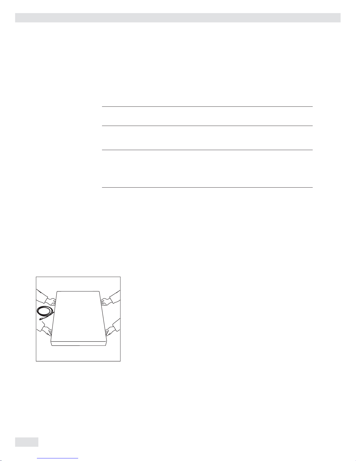
For devices with a platform size of 60 x 80 cm or larger:
t Protective gear must be worn (safety shoes and if required, gloves)
t Always lift on the side walls when lifting or transporting the weighing platform.
t After unpacking the device, check it for any visible damage as a result of rough
handling during shipment.
y If you detect any damage, proceed as directed in the chapter entitled “Care and
Maintenance“ under “Safety Inspection.“
t Save the original packaging for any future transport.
Unplug all connected cables before packing the equipment.
Checking Package Contents
– Indicator
– Weighing platform
– Operating instructions
– Options (special accessories) as listed on the bill of delivery
8 Operating Instructions Combics Complete Scales
Installation
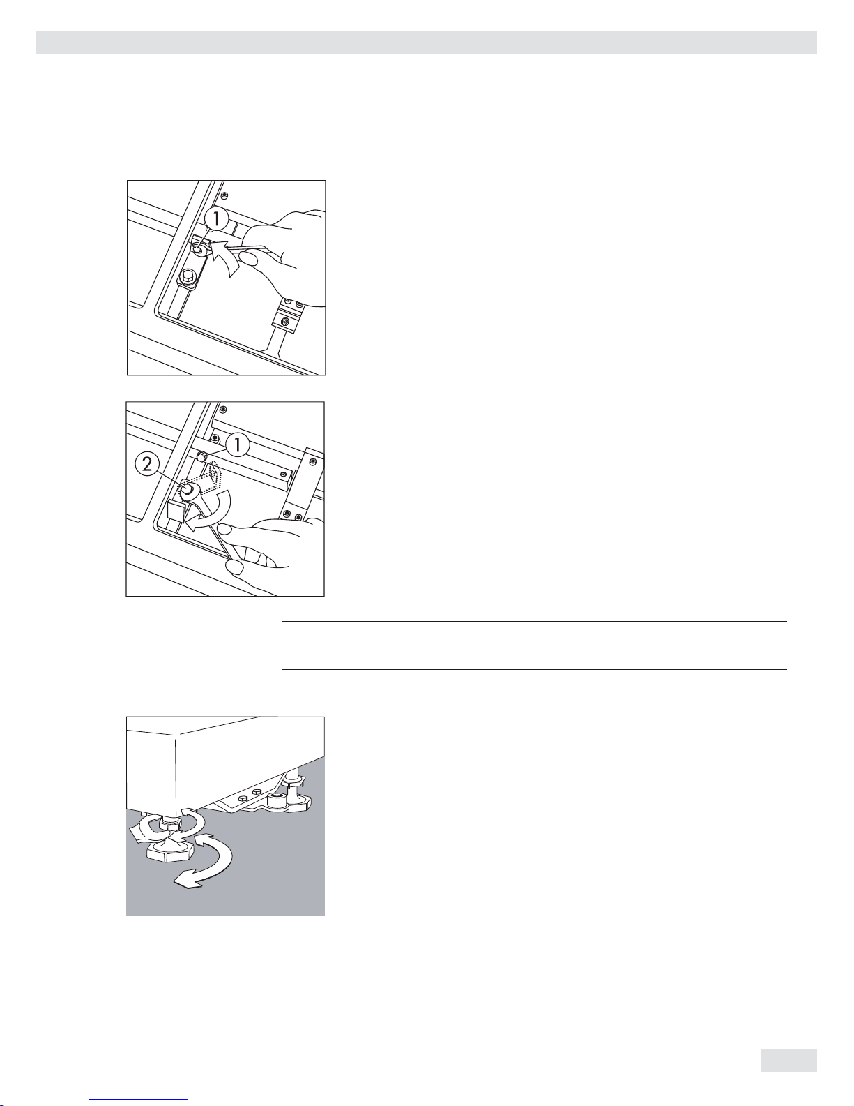
CAH3 models: Remove transport locks
t Place the weighing platform at its installation location, remove the
weighing pan.
t Remove the transport lock: Remove screw 1
t Loosen screw 2.
t Turn the mounting bracket 180° and re-secure screw 2.
t Re-attach screw 1 to the lever
3
The transport lock must be re-installed before transporting the weighing platform.
Leveling the Weighing Platform
The weighing platform must be exactly level to ensure reproducible weighing results
every time. Therefore, the weighing platform must always be re-leveled after it has
been moved to a different location.
t Remove the weighing pan.
t Loosen the lock nuts using a wrench (SW17).
t Use a SW5 Allen key to screw the leveling feet in/out.
Turning the leveling feet clockwise lifts the weighing platform,
turning the leveling feet counterclockwise lowers the weighing platform.
Operating Instructions Combics Complete Scales 9

Installation
10 Operating Instructions Combics Complete Scales
t Align the weighing platform leveling feet so that air bubble is centered within
the circle of the level indicator.
t Check to ensure that all four leveling feet rest securely on the work surface.
y Each of the leveling feet must support an equal load.
t Re-fasten the lock nuts after leveling:
Small platforms (1 measuring cell) counter to the platform frame,
large platforms (4 measuring cells) counter to the platform foot.
t Place the weighing pan on the scale.
Operating Limits
You should not exceed the highest load for weighing platforms.
The highest capacity for the weighing platform is as follows depending on the load
used (center, side, one-sided corner load):
Platform size Center Side Corner
320 + 240 50 35 20
400 + 300 130 85 45
500 + 400 300 200 100
500 + 400 P* 600 400 200
650 + 500 S** 450 300 150
800 + 600 P* 1200 800 400
800 + 600 S** 900 600 300
800 + 800 4500 3000 1500
1000 + 800 4500 3000 1500
1000 + 1000 4500 3000 1500
1250 + 1000 4500 3000 1500
1500 + 1250 4500 3000 1500
1500 + 1500 4500 3000 1500
2000 + 1500 4500 3000 1500
* Steel
** Stainless steel
For CAH* models Platform size Supported load (center) in kg
400 + 300 130
560 + 450 130
800 + 600 600

Shock Resistance
The weighing platform has a robust design; however, falling weighing samples, side
impacts and shocks should be avoided. The weighing platform can withstand loads
specifi ed in the DIN standard IEC68 Part 2-27.
Notes on Planning Superstructures
3
Superstructures must be completely attached before the weighing platform is
connected to the power.
The weighing platform is designed for system integration. Scale drawings are the
basis for the selection of the required superstructures. The fi xing of model CAH*IG*
weighing platforms should be carried out using the YAS04IS fastening kit.
Moving or rotating parts on the weighing pan must be designed so that the
weighing results are not infl uenced. Rotating parts should be counterbalanced, for
example.
The weighing pan must be free on all sides so that there is no connection between
the weighing platform and fi xed parts due to falling parts or dirt. Cables and hoses
between the weighing platform and other devices may not exert any forces on the
weighing platform. These cables may not touch the weighing pan.
When setting up systems in hazardous areas (Zone 2 or 22), any relevant
specifi cations should be observed, e. g.: EN60079-14.
The design should ensure that moving parts do not cause electrostatic discharges
(e.g. roller conveyors).
Preload Range (Zero Set Range)
The weight of the superstructures that are attached to the weighing platform is
designated as a “preload.“ The preload is electronically compensated for in the
weighing platform so that the full weighing range remains available and thus
zeroing and/or adjustment (with external weights) is possible.
Greater preloads reduce the weighing capacity. You may not fall below the following
weighing range values:
– For CAH*E-16ED... and CAH*E-32ED... a min. 20 kg weighing range must be
maintained
– For CAH*E-64ED... and CAH*G-64FE... a min. 35 kg weighing range must be
maintained
– For CAH*G-150IG-H and CAH*G-300IG-H a min. 60 kg weighing range must be
maintained
The preload must always be set before verifi cation.
Acclimatizing the Device
Condensation can form on the surfaces of a cold device when it is brought into a
substantially warmer area.
t Allow the device to acclimatize for about 2 hours at room temperature, leaving
it unplugged from AC power.
Installation
Operating Instructions Combics Complete Scales 11

Getting Started
Steps 1.) Set up the weighing platform with the indicator.
2.) Level the weighing platform
3.) Connect peripheral devices, e.g. printer to the COM1 or UNICOM interface:
see Data Interfaces chapter starting on page 99
4.) Connecting the device to AC power
5.)
Carry out an alignment: for adjustment, see page 27, for linearization see page 24
Connecting Peripheral Devices or Another Weighing
Platform
An analog Sartorius platform (CAPP, CAPS) or an IS weighing platform is connected
at the factory to the Combics indicator WP1 input.
3
The load cell should be connected by a certifi ed technician who has received
specialized training from Sartorius. Any installation work that does not conform
to the instructions in this manual results in forfeiture of all claims under the
manufacturer’s warranty.
3
Peripheral devices should be connected by a certifi ed technician who has received
specialized training from Sartorius. Any installation work that does not conform
to the instructions in this manual results in forfeiture of all claims under the
manufacturer’s warranty.
3
Disconnect the equipment from the power supply before starting connection work.
t Place cables from peripheral devices next to the indicator.
CAW3S, CAH3 (IP69K) t Opening the Combics indicator:
Loosen the ten cap nuts on the front panel. Remove the front panel.
Installing Connection and Interface Cables
3
The cable gland (IP69K protection) is pre-mounted on the indicator. Please use
extreme caution when performing any work on the equipment that affects this
cable gland.
You must use a torque wrench. The torque for this cable gland is 5 Nm.
Preparing Cables
t Strip approx. 14 cm from the end of the cable.
t Shorten the shielding to approx. 2 cm and pull back over the insulation.
t Strip approximately 5 mm of the insulation from the wires of the connecting
cable and affi x ferrules to the wire ends.
Getting Started
12 Operating Instructions Combics Complete Scales
Attaching the Cable Entry
3
Please use extreme caution when performing any work on the equipment that
affects this cable gland.
You must use a torque wrench.
The torque for this cable gland is 5 Nm.
4
1
5
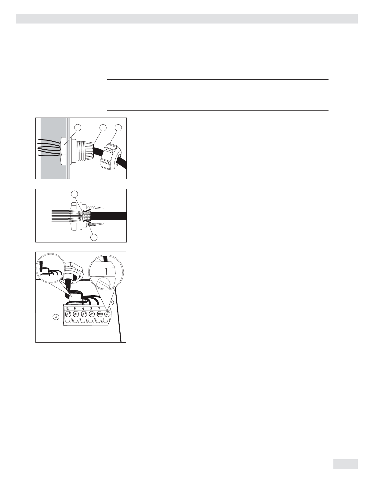
t Remove the protective cap from the bore hole on the indicator.
t Insert the included cable gland through the bore hole and secure from the inside
using the locknut (1).
2
3
t Insert the cable through the cable gland until the shielding (2) comes into
contact with the clamps (3). Tighten the screw-down nut (4) until the gasket (5)
inserted between the screw-down nut and cable forms a small beaded rim.
t Check the shielding and clamps.
t Securely connect the wires of the connecting cable in accordance with the
terminal assignments.
t After you close the housing again, use a pressure gauge to check the integrity of
the IP69K protection. For details, contact the Sartorius Service Center.
Connecting Cables
t Insert all cable wires through the ferrite case, wind them around the ferrite case
and then reinsert back through the ferrite case.
t Screw the wires tightly into the clamps.
See the following pages for terminal pin allocation
t Refer to the data sheet or operating instructions of the
weighing platform for details on the assignment of wire
colors/signals. Ensure any lines that are not assigned
are insulated correctly.
t When connecting a load receptor that uses 4-conductor technology (the cable
of the weighing platform to be connected only has 4 lines), connect clamp
pairs 1 and 2 (EXC+ und SENSE+), and 5 and 6 (SENSE- und EXC-) with a wire
jumper.
Connecting an IS Weighing Platform to a Combics 3
You can connect an IS weighing platform to WP2.
Features – IS weighing platforms process weighing data independently of the indicator.
– Internal adjustment option
– IS...-0CE models: have a separate approval number, printed on a tag that is
affi xed to the cable.
– Please observe the conditions described in the manual for the weighing platform
you connect.
Getting Started
Operating Instructions Combics Complete Scales 13

14 Operating Instructions Combics Complete Scales
Getting Started
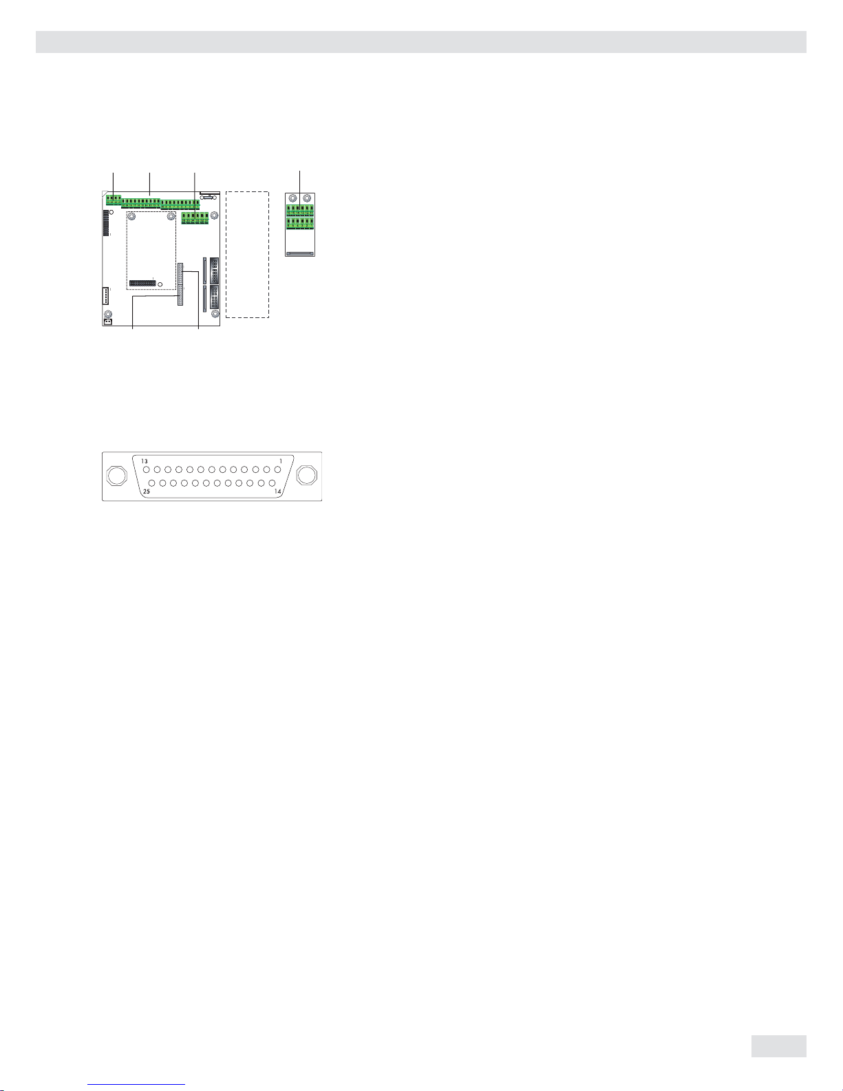
Connecting Peripheral Devices or a 2nd Weighing
Platform: Combics 3, Model type CAW3S | CAH3
PS2 COM1 COM2 A8
Keypad
LED + Display
Weighing platform
Interface 2
Digital PCB
COM1, COM2 and PS2 terminal assignments (applies to all PCBs)
PS2
1 LOAD_PRINTER 11 Clear to send (CTS) 21 5 V switched
2 RESET_OUT 12 Data terminal ready (DTR) 22 PS/2_data
3 GND 13 Data input (RXD) 23 PS/2_clock
4 GND 14 Data output (TXD) 24 GND
5 5V_OUT 15 GND COM2
6 5V switched 16 Universal In 31 CTS_COM2
7 GND 17 Control output: “lower“ 32 DTR_COM2
8 GND 18 Control output: “equal“ 33 RXD_COM2
9 n.c. 19 Control output: “heavier“ 34 TXD_COM2
10 LINE_OUT 20 Control output: “set“ 35 GND
36 GND
A8 terminal assignments
1 EXC+ Bridge supply voltage (+)
2 SENSE+ Sense (+) for bridge supply voltage
3 OUT+ Measuring voltage positive
4 OUT- Measuring voltage negative
5 SENSE- Sense (-) for bridge supply voltage
6 EXC- Bridge supply voltage (–)
Keys
LED + Display
A6/7
Tastatur
LED + Display
PS2 COM1 COM2
Interface PCB for RS-232/485 for IS weighing platform
(option A6/A7)
A6/7 terminal assignments
1 CTS 11 TxD/RxD+
2 DTR 12 TxD/RxD-
3 RxD 13 LINE_OUT
4 TxD 14 LINE_OUT
5 GND 15 GND
6 Adjustment Lock 16 GND
Keys
LED + Display
A20
Keypad
LED + Display
PS2 COM1 COM2
Weighing platform
Interface 1
Interface PCB for ADC 10.000e (option A20)
A20 terminal assignments
1 EXC+
2 SENSE+
3 OUT+
4 OUT-
5 SENSE-
6 EXC-
Keys
LED + Display
A62/72
KeypadLED + Display
PS2 COM1 COM2
Weighing platform
Interface 1
Interface PCB for RS-232/485 for IS weighing platform
(option A62/A72)
Interface PCB A6/7 and A62/72
1 CTS 11 TxD/RxD+
2 DTR 12 TxD/RxD-
3 RxD 13 LINE_OUT
4 TxD 14 LINE_OUT
5 GND 15 GND
6 Adjustment Lock 16 GND
Keys
LED + Display
Interface Pin Assignment Chart COM1
Model type CAW3P (IP44 protection)
COM1 female connectors:
25-pin D-Submini female connector (DB25S) with screw lock hardware for cable
gland
Recommended interface connector:
25-pin D-Submini (DB25) with shielded cable clamp assembly and shield plate
(Amp type 826 985-1C) and fastening screws (Amp type 164868-1)
COM1 pin assignments
Pin 1: Shield
Pin 2: Data output (TxD)
Pin 3: Data input (RxD)
Pin 4: GNO
Pin 5: Clear to send (CTS)
Pin 6: Not assigned
Pin 7: Internal ground (GND)
Pin 8: Internal ground (GND)
Pin 9: Not assigned
Pin 10: Not assigned
Pin 11: +12V for printer
Pin 12: RES_OUT\
Pin 13: +5 V switch
Pin 14: Internal ground (GND)
Pin 15: Universal switch
Pin 16: Control output: “lower“
Pin 17: Control output: “equal“
Pin 18: Control output: “heavier“
Pin 19: Control output: “set“
Pin 20: Data terminal ready (DTR)
Pin 21: Ground power supply (GND)
Pin 22: Not assigned
Pin 23: Not assigned
Pin 24: Power supply +15..25 V (peripherals)
Pin 25: +5 V
Operating Instructions Combics Complete Scales 15
Getting Started

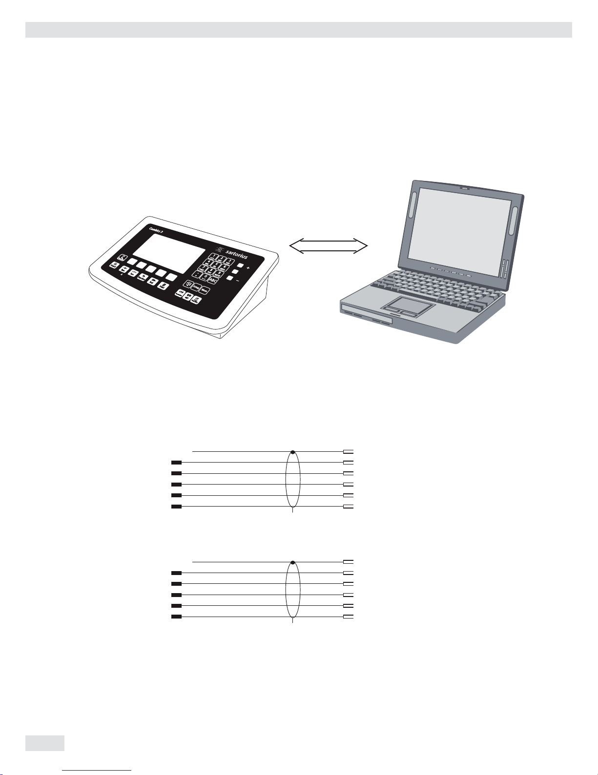
Connecting a PC via Interface COM1
Use the following cables to connect a PC to the indicator in accordance with the
RS-232C/V24 standard (max. cable length 15 m):
Model type CAW3P: connecting cable 7357312
Model type CAW3S | CAH3: connecting cable YCC02-D09F6
Pin assignment
Pin assignments for the cable from the indicator to an RS-232 PC interface (COM1).
Indicator side PC side
Model type CAW3P DSUB connector
25-pin D-Sub male connector 9-pin or 25-pin
1
Sgn GND 7 5 GND 7 GND
TxD 2 2 RxD 3 RxD
RxD 3 3 TxD 2 TxD
DTR 20 8 CTS 5 CTS
CTS 5 4 DTR 20 DTR
Model type CAW3S | CAH3
Open cable end DSUB connector
9-pin or 25-pin
Sgn GND 15 5 GND 7 GND
TxD 14 2 RxD 3 RxD
RxD 13 3 TxD 2 TxD
DTR 12 8 CTS 5 CTS
CTS 11 4 DTR 20 DTR
RS232
Getting Started
16 Operating Instructions Combics Complete Scales

Interface Pin Assignment Chart COM2
Model type CAW3P (IP44 protection)
COM1 female connectors:
25-pin D-Submini female connector (DB25S) with screw lock hardware for cable
gland
6
5
1
9
Recommended interface connector:
25-pin D-Submini (DB25) with shielded cable clamp assembly and shield plate
(Amp type 826 985-1C) and fastening screws (Amp type 164868-1)
COM1 pin assignments
Pin 1: Shield
Pin 2: Data output (TxD)
Pin 3: Data input (RxD)
Pin 4: GNO
Pin 5: Clear to send (CTS)
Pin 6: Not assigned
Pin 7: Internal ground (GND)
Pin 8: Internal ground (GND)
Pin 9: Not assigned
Pin 10: Not assigned
Pin 11: +12 V for printer
Pin 12: RES_OUT\
Pin 13: +5 V switch
Pin 14: Internal ground (GND)
Pin 15: Universal switch
Pin 16: Control output: “lower“
Pin 17: Control output: “equal“
Pin 18: Control output: “heavier“
Pin 19: Control output: “set“
Pin 20: Data terminal ready (DTR)
Pin 21: Ground power supply (GND)
Pin 22: Not assigned
Pin 23: Not assigned
Pin 24: Power supply +15..25 V (peripherals)
Pin 25: +5 V
Getting Started
Operating Instructions Combics Complete Scales 17
Connecting a PC via Interface COM2
Use the following cables to connect a PC to the indicator in accordance with the
RS-232C/V24 standard (max. cable length 15 m):
Model type CAW3P: connecting cable 7357312
Model type CAW3S | CAH3: connecting cable YCC02-D09F6
Pin assignment
Pin assignments for the cable from the indicator to an RS-232 PC interface (COM1).
Indicator side PC side
Model type CAW3P DSUB connector
25-pin D-Sub male connector 9-pin or 25-pin
1
Sgn GND 7 5 GND 7 GND
TxD 2 2 RxD 3 RxD
RxD 3 3 TxD 2 TxD
DTR 20 8 CTS 5 CTS
CTS 5 4 DTR 20 DTR
Model type CAW3S | CAH3
Open cable end DSUB connector
9-pin or 25-pin
Sgn GND 15 5 GND 7 GND
TxD 14 2 RxD 3 RxD
RxD 13 3 TxD 2 TxD
DTR 12 8 CTS 5 CTS
CTS 11 4 DTR 20 DTR
RS232
Getting Started
18 Operating Instructions Combics Complete Scales

3
1
4
2
6
5
Interface Pin Assignment Chart PS2
Model type CAISL (IP44 protection)
PS2 female connector:
6-pin miniature socket PS2 (Mini-DIN)
Recommended interface connector:
6-pin miniature socket PS2 with integrated shielded cable clamp assembly
Pin assignment:
Pin 1: Keyboard data (data interface cable)
Pin 2: Not assigned
Pin 3: Internal ground (GND)
Pin 4: +5V switched
Pin 5: Keyboard clock
Pin 6: Not used
Connecting a Bar Code Scanner
Accessory YBR02CISL
t Disconnect the indicator from AC power (unplug the AC adapter)
For CAW3P models:
t Connect the barcode scanner via PS/2.
For CAW3S | CAH3 models:
t Pin assignment, see “Connecting Peripheral Devices“ (implemented via the
YCC02-BR02 connecting cable or as option M8) on page 14.
NOTE: This equipment has been tested and found to comply with the limits pursuant to part 15 of FCC Rules. These limits are designed to provide reasonable
protection against harmful interference. This equipment generates, uses and can
radiate radio frequency energy and, if not installed and used in accordance with
these instructions, may cause harmful interference to radio communications. For
information on the specific limits and class of this equipment, please refer to the
Declaration of Conformity. Depending on the particular class, you are either required
or requested to correct the interference. If you have a Class A digital device, you
need to comply with the FCC statement as follows: “Operation of this equipment in
a residential area is likely to cause harmful interference in which case the user will be
required to correct the interference at his own expense.“
Getting Started
Operating Instructions Combics Complete Scales 19
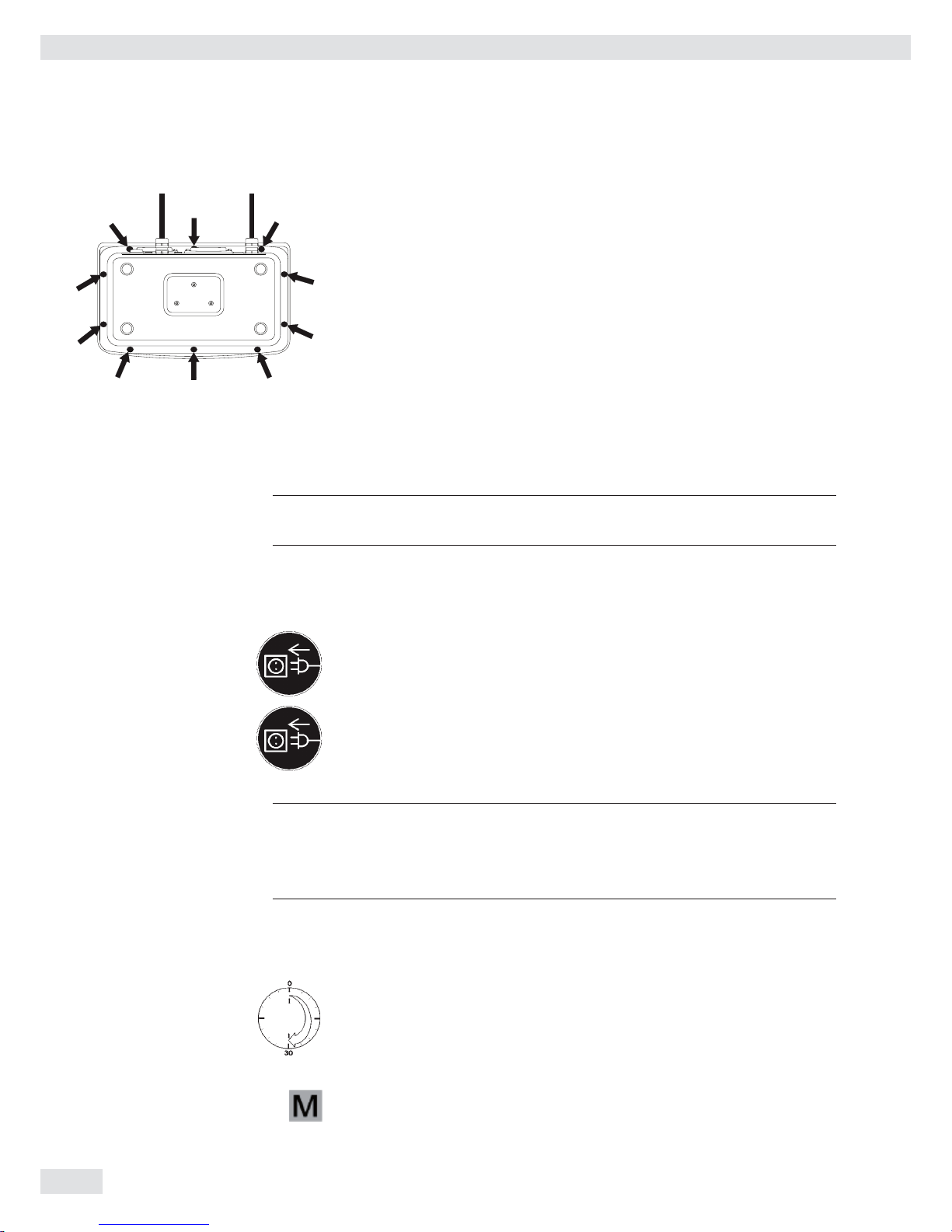
Closing the Combics Indicator
t Re-attach the front panel and secure it with the ten cap nuts ( 1Nm ).
Connecting the Device to AC Power
The indicator is powered through the pre-installed power cord. The power supply is
integrated into the indicator. The device can be operated with a supply voltage of
100 V to 240 V.
3
The power connection must be made in accordance with the regulations applicable
in your country.
The printed voltage rating (see type label) must match the voltage in the place of
installation. If the voltage specified on the label or the plug design of the AC adapter
do not match the rating or standard you use, please contact your Sartorius office or
dealer.
t Check the voltage rating and plug design.
t The device must be plugged into a properly installed wall outlet.
Protection Class 1 Device
t The device must be plugged into a properly installed wall outlet which has a
protective grounding conductor (PE).
Safety Precautions
3
If you use an electrical outlet that does not have a protective grounding conductor,
ensure that an equivalent protective conductor is installed by a certified electrician
(as specified in the applicable regulations for installation in your country).
The protective effect must not be negated by using an extension cord without a
protective grounding conductor.
Before using for the first time, any superstructure parts must be completely installed.
Avoid connecting the equipment to lines that have a heavy electrical load,
e.g. compressors, large machinery, etc.
Warm-up Time
To deliver exact results, the device must warm up for at least 30 minutes after
connection to AC power. Only after this time will the device have reached the
required operating temperature.
Using a Verified Device in Legal Metrology
Ensure that there is a warm-up time of at least 24 hours after connection to the
power supply.
Getting Started
20 Operating Instructions Combics Complete Scales
Configuring Weighing Platforms
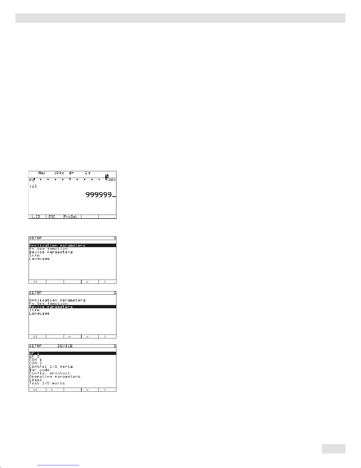
Service-Mode
Purpose The Service mode enables access to additional menu items in the Setup menu
which are not displayed when the Service mode is not active. The most important
calibration and adjustment work for the indicator and for the connected weighing
platform can be carried out in the Service menu, e.g. ADC configuration.
When the Service mode is active, an “S” is shown in the top right-hand corner of
the display. To deactivate the Service mode, restart the indicator (turn the indicator
off and back on again).
Activating the Service Mode
t Press e to turn on the device.
y When turned on the scale is in an application program.
t Enter the service password (see Appendix General User Password) and press
M to confirm.
y The device in now is Service mode. An “S“ appears in the top right-hand
corner of the display.
t Press the “q“ soft key several times to select the “Device
parameters
“ line.
t Press the “O“ soft key.
y The “Device“ submenu will open.
t Select and open the corresponding submenu. Repeat this procedure until the
desired menu item in the lowest menu level can be opened.
t View or change the menu item (confirm with “l“) and use “o“ to return to the
previous menu.
t Press M or “oo“ to exit the Setup menu.
Exiting Service Mode
Turn the device off and then on again to return to the normal application mode.
If you exit the Setup menu without changing settings by confirming with M or
the “oo“ soft key, the Service mode will remain active. Press the M key to
re-open the Setup menu.
Operating Instructions Combics Complete Scales 21
Configuring Weighing Platforms
Overview of the Setup Menu in Service Mode
o = Factory setting
x = User-defi ned setting
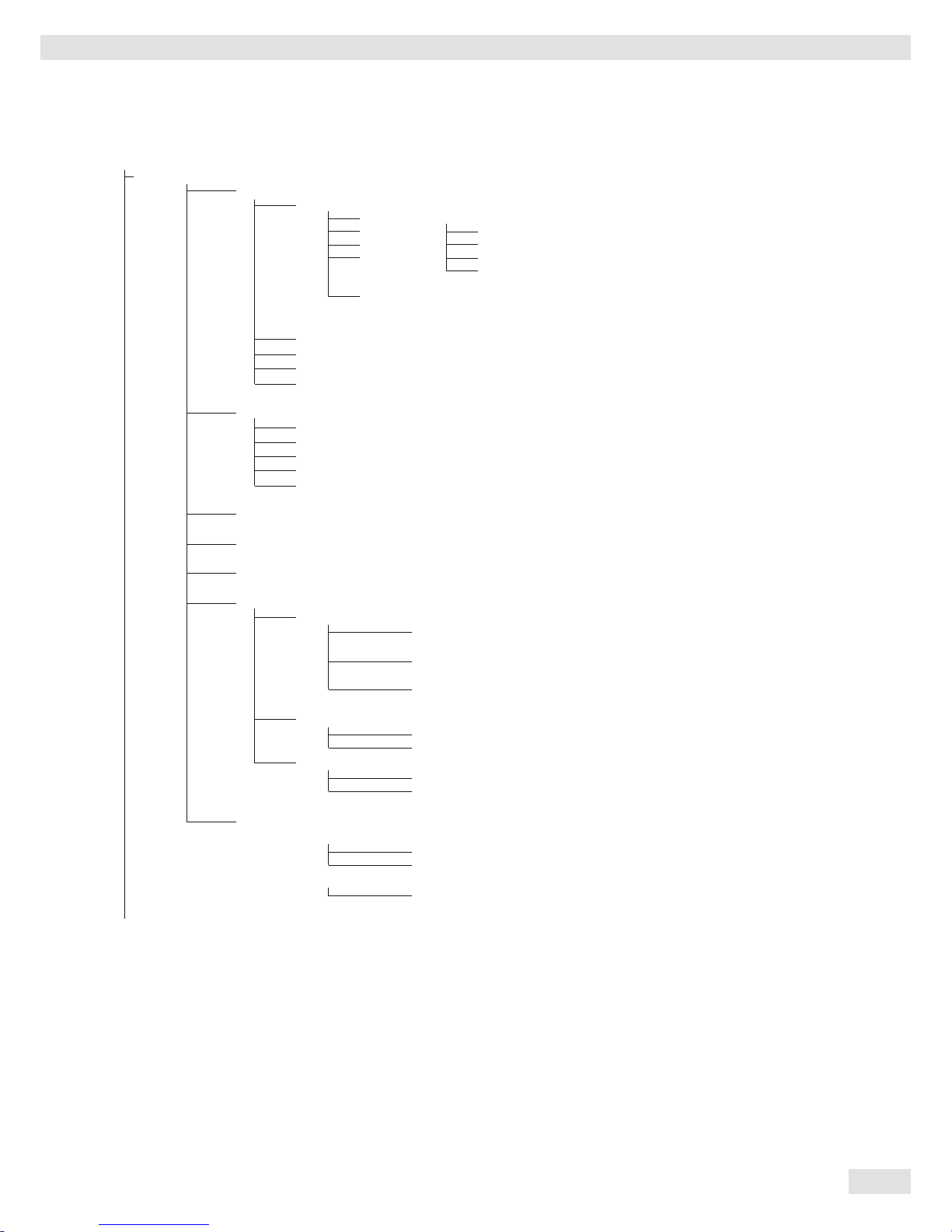
Service password entry Setup Application parameters, please refer to the “Basic Application Programs” manual
Fn key “Setup Overview (Parameters)“
Device parameters
Info, see the “Setup Overview (Parameters)“ section
Language, see the “Setup Overview (Parameters)“ section
Setup access with service password
Device parameters
WP1
RS-232
1
)
SBI standard
SBI verifi able
o IS-232
ADC-232
RS-485 1)
o IS-485
ADC-485
Internal
ADC confi guration (see the “Setup Menu for ADC Confi guration“ section)
Calibration/Adjustment
CAL key function
o Ext. cal./adj.; factory-def. wt.
Ext. cal./adjust.; user-defi ned weight
Ext. lineariz.; factory-def. wts
Ext. lineariz.; user-def. wts
Set preload
Delete preload
Key blocked
Cal./adj. sequence
Cal. then auto adjust
o Cal. then manual adjust
isoCAL function 3)
o Off
Adjustment prompt
Activate external adjustment 2)
o Activated
Deactivated
Parameter for external weight
Cal./adj. weight:
Lin. weight 1...4:
Adjust without weights 2)
Input parameters
Nominal load:
Resolution:
Sensitivity 1…4:
Save parameters
Yes
o No
Geographical data 2)
Input parameters
Geographical latitude
Altitude
Gravitational acceleration
Save parameters
Yes
o No
1
) Equipment version: – then blocked internally
2
) Not available on devices verifi ed for use in legal metrology
3
) Only when operated with Sartorius IS weighing platforms or an external ADC
22 Operating Instructions Combics Complete Scales
Confi guring Weighing Platforms
Device Parameters
WP1
Internal
Calibration/Adjustment unit
Grams /g
Kilograms /kg
Tons /t
o Pounds /lb
Menu items “Adapt fi lter“ - “Factory settings: only bal. func,“
see the “Setup Overview (Parameters)“ section
Off
COM-1 (when the WP is assigned to this interface)
COM-2 (when the WP is assigned to this interface)
UNICOM (only if available)
WP2, see the “Setup Overview (Parameters)“ section
RS-232
1
) similar to “Internal“ menu for WP1
RS-485
1
) similar to “Internal“ menu for WP1
o Off
COM-1 similar to WP 1
COM-2 similar to WP 1
COM-1, see the “Setup Overview (Parameters)“ section
COM-2, see the “Setup Overview (Parameters)“ section
“Control I/O ports“ - “Terminal data,“ see the “Setup Overview (Parameters)“ section
SQmin
SQmin input
SQmin WP1
SQmin WP1 0.000 kg
SQmin WP2
SQmin WP2 0.000 kg
SQmin WP3
SQmin WP3 0.000 kg
Display
No
o Yes
GMP print
o No
Yes
Alibi memory
2
)
Clear alibi memory
Yes
o No
Alibi memory period
In days 90
1
) Equipment version: – then saved internally
2
) Only if alibi memory is available (option)
Operating Instructions Combics Complete Scales 23
Confi guring Weighing Platforms

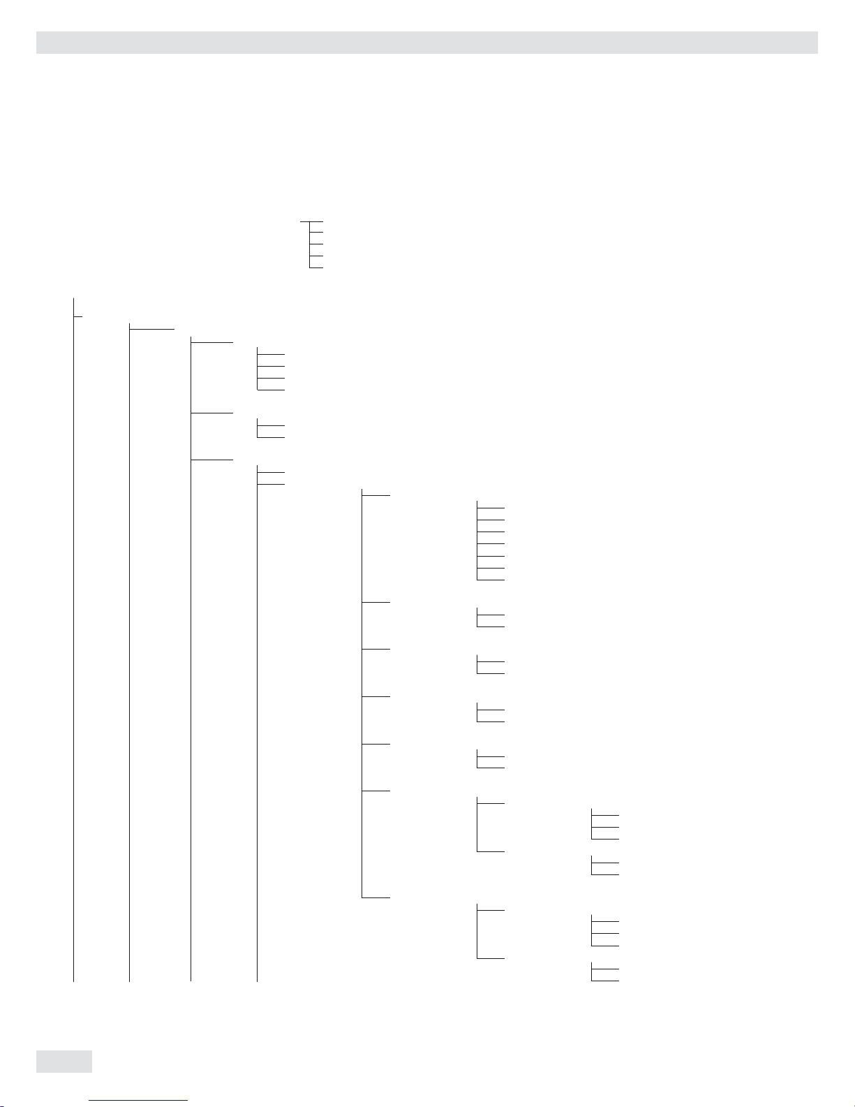
Setup Menu for A/D Converter Configuration
Setup access in Service mode
WP1 – Internal – ADC confi guration
Standard confi guration Ranges Single-range mode Scale interval d
Max. cap.
Multi-interval mode Scale interval d
Range 1
Range 2
Range 3
Max. cap.
Multiple-range Scale interval d
mode Range 1
Range 2
Range 3
Max. cap.
Available units User-defi nable /o
Grams /g
Kilograms /kg
Carats /ct
...
Save parameters Yes
o No
o Verifi able Accuracy Class III/IIII
confi guration class
Ranges Single-range mode
D:
E:
Min. capacity:
Max. cap.:
Multi-interval mode
D:
E:
Min. capacity:
Range 1:
Range 2
Range 3:
Max. cap.:
Multi-interval mode
D:
E:
Min. capacity:
Range 1:
Range 2
Range 3:
Max. cap.:
Available units
User-defi nable /o
o Grams /g
o Kilograms /kg
...
Save parameters
Yes
o No
24 Operating Instructions Combics Complete Scales
Confi guring Weighing Platforms

Analog/Digital Converter (ADC)
Purpose Adjust the parameters of the analog/digital converter to the connected load cell or
weighing platform. After ADC confi guration, the ADC in connection with the load
sensor is defi ned as a scale.
3
Once the ADC confi guration has been locked, the indicator can no longer be used
to infl uence weighing results. The scope of functions available in the weighing
instrument is defi ned by the A/D converter. Weighing functions that can be
activated include reading weight values, taring, adjustment, reading the tare value,
saving/deleting the tare entry.
Setup Information – ADC confi guration is only possible when the menu access switch is open.
Re-close the menu access switch after ADC confi guration.
– Before ADC confi guration, you must fi rst set whether or not the weighing
platform will be used as a standard or verifi able weighing platform.
– ADC confi guration is carried out in the Service mode in the Setup menu under
“WP 1“ for the fi rst weighing platform and “WP 2“ for the second.
– Entries made in ADC confi guration will not be affected by a menu reset
(returning the setup parameters to their factory settings).
See also the overview in the “Setup Menu for A/D Converter Confi guration“ section.
Setting Parameters for ADC Configuration
Standard or Verifiable Configurations In ADC confi guration, you must fi rst select whether the weighing platform should
be confi gured as a standard or verifi able (for use in legal metrology) weighing
platform.
– Standard confi guration “Standard“
– Verifi able confi guration “Verifi able“
Select using the “Q“ or “q“ soft key. Press the “O“ soft key to confi rm the setting
and open the Confi guration menu.
Accuracy Class This menu item is not shown when the Standard confi guration is active. When
the Verifi able confi guration is active (for weighing platforms verifi ed or verifi able
for use in legal metrology), only Class l/m can be selected. Activate the
“Accuracy class“ menu item, select “Class III/IIII“ and
confi rm your selection using the “l“ soft key.
Ranges The capacity of the weighing platform can be divided into multiple ranges:
– “ Single-range mode“:
The entire weighing range is divided into scale intervals on the basis of the
lowest interval d and the maximum load.
– “ Multi-interval mode“:
The “Multi-interval mode” function divides the weighing capacity into as
many as four ranges, each with a different readability. Corresponding changes
take place automatically. Once the scale has been tared, the highest possible
resolution is available even if the weighing platform is loaded with a higher
weight. This is only permitted in the accuracy classes l/m for the verifi able
confi guration.
– “ Multiple-range mode“:
Multiple-range mode has two or three weighing ranges. When the range limit
is exceeded, the scale switches into the next highest weighing range (lower
resolution) and remains there. The scale can be returned to the lower weighing
range (higher resolution) only by pressing the ( key and then unloading the
scale.
Operating Instructions Combics Complete Scales 25
Confi guring Weighing Platforms

Select the desired confi guration using the “Q“ or “q“ soft key. Confi rm your
selection using the “O“ key. Make additional settings in the submenu: scale interval
d/verifi cation scale interval e, minimum load (Verifi able confi guration only),
range limits (Multi-interval or Multiple range mode only) and maximum capacity.
Confi rm using the “l“ soft key or cancel using “Esc.“
Scale Interval d Scale interval d indicates the resolution of the weighing instrument.
The scale interval d can be entered only in increments of 1, 2, 5, 10, 20, etc.
When using verifi able or verifi ed weighing platforms, the scale interval d is the same
as the verifi cation scale interval e.
Verification Scale Interval e The verifi cation scale interval e indicates the resolution of the weighing instrument
in legal metrology. The verifi cation scale interval e can be entered only in
increments of 1, 2, 5, 10, 20, etc. For weighing instruments of accuracy class l or
m, e = d. This is why the scale interval d does not need to be entered separately.
When “Standard confi guration” is used, this menu item is not displayed.
Minimum Capacity (Min. Cap.) When “Standard confi guration” is used, this menu item is not displayed. The
minimum load of the connected weighing platform is entered under this menu item.
The minimum load for scales of accuracy class l is 20 e and 10 e for class m.
Important Note: The function of the minimum load setting is to warn operators that below this
limit, the summation of tolerances might lead to signifi cant measurement errors. In
Germany, for example, initial weights below the minimum load are not allowed.
Maximum Capacity (Max. Cap.) The maximum capacity is the maximum load that may be placed on the weighing
instrument. When heavier weights are used the weighing instrument displays
overload “H.” The scale intervals of the weighing instrument are calculated using
the maximum load and the scale interval d (e.g. max. capacity = 15.000 kg, smallest
scale interval d = 0.005 kg yields 3000 scale intervals).
In legal metrology the total number of intervals must be no more than 3000 e, and
when using multi-interval scales there must not be more than 3000 e intervals per
range.
In standard operation, as opposed to legal metrology, you can defi ne a “Super
Range” weighing instrument of over 3000 intervals. These parameters, however,
may be infl uenced by physical restrictions.
Range 1, Range 2, Range 3 The range limits are entered for the individual ranges. The accuracy changes when
these limits are exceeded. The following applies when entering limits: range 1
< range 2 < range 3 < maximum capacity.
This means that the weighing range can be divided into a maximum of 4 ranges.
The resolution changes at intervals of 1, 2, 5, 10, 20 etc., where the lowest
resolution is the smallest scale interval entered. Set ranges that are not required for
use to zero.
Available Units With this function, you can make particular weight units (weight unit x, x=1, 2)
inaccessible during weighing. Available units are indicated by a * on the display
(more than one can be selected).
To enable or disable a unit, select the unit by pressing the “
Q“ or “q“ soft key, and
then press the “l“ soft key (toggle function).
Saving Parameters To save the ADC confi guration, use the “
O“ soft key to select “Yes“ and confi rm
with the “l“ soft key. The device software is reset, and the scale returns to the
normal weighing mode. To exit the menu without saving confi guration changes,
press the “o“ soft key.
Once these parameters have been confi gured, the A/D converter in conjunction with
the load cell(s) is defi ned as a weighing instrument. The A/D converter, in conjunc-
tion with the weighing platform, can now be used like any standard weighing
platform. In addition, the weight unit must be defi ned and the weighing platform
adjusted (calibration, adjustment and linearization must be performed). For a detailed
description of these procedures, see the “Adjustment in Service Mode“ section.
26 Operating Instructions Combics Complete Scales
Confi guring Weighing Platforms

Analog/Digital Converter (ADC) Configuration
Condition The weighing platform must already be connected.
Open the Menu Access Switch The menu access switch is located on the back of the indicator right next to the
weighing platform connection.
t Remove the cap.
t Slide the switch to the left (= “open“ position).
Activating the Service Mode t See “Service Mode“ on page 17.
Configuration t Select weighing platform “WP 1.“
t If the “Internal“ setting is not already activated (marked by “o“), select
the setting using the “Q“ or “q“ soft key and confi rm with “O.“
y The message “Function active“ appears briefl y. The “WP 1 internal“
menu will then open.
t Open the ADC Confi guration menu.
t Select the desired confi guration data record using the “Q“ or “q“ soft key:
“Standard“ or “Verifi able“ (verifi able confi guration).
The default setting depends on the data record.
t Open the menu for confi guring A/D converter parameters. In this example, the
menu for ADC confi guration of a weighing platform for use in legal metrology
is opened.
If “Standard“ was selected previously, then the “Accuracy
class
“ is not displayed.
t Open the fi rst menu item.
For a standard confi guration, the “Ranges“ menu item, for a verifi able
confi guration, the “Accuracy class“ menu item.
When the “Verifi able” confi guration is active, always select the “Accuracy
class
“ menu item fi rst.
t Set accuracy class l/m. The “o“ symbol should mark the setting, if required
confi rm using the “l“ soft key.
t Press the “o“ soft key to exit the menu item.
t Open the “Ranges“ menu item.
Operating Instructions Combics Complete Scales 27
Confi guring Weighing Platforms
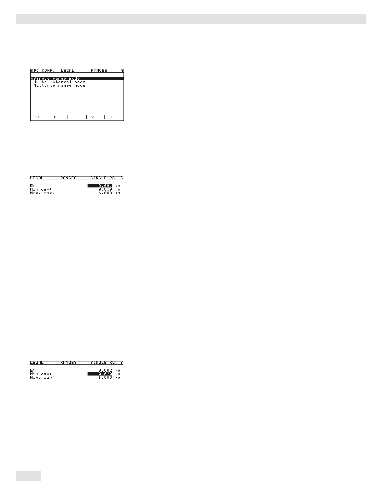
In the example shown here, “Single range mode“ has been selected
(marked by “o“).
t To select a different weighing range confi guration, use the “Q“ or “q“ soft key
to select the corresponding line and open the selected menu using the “O“ soft
key.
y The selected weighing range confi guration is now active. When you return
from the input menu for entering the weighing range parameters, the new
range confi guration is marked by a “o.“
For more information about range confi guration, please see “Setting Parameters for
ADC Confi guration.“
The default values displayed depend on the data record loaded and might have
to be changed. In the example shown here, the A/D confi guration is set with a
“Verifi able” data record in single-range mode.
Single-range Mode t Select the individual input fi elds using the “
Q“ or “q“ soft key.
t For numeric input: use the 0 ... 9 keys and the . key (decimal point).
Make corrections using c.
t Confi rm using the “l“ soft key.
If other parameters follow the one just entered, the highlight bar is
automatically positioned on the next input fi eld.
To cancel numbers entered: press the “ESC“ soft key.
t Use the “
o“ soft key to go to the next menu level.
y This will apply all parameters.
t Press M or “oo“ to exit the Setup menu.
0 . 0 0 2
In the example shown here, a single-range scale in “Verifi able” confi guration
with a maximum capacity of 6.000 kg is modifi ed; the verifi cation scale interval
e is changed from 0.001 kg to 0.002 kg, in accordance with the maximum
permitted value of 3000 verifi cation scale intervals. Press the “l“ soft key to
confi rm the changed value.
The highlight bar is automatically positioned on the “Min. cap.“ fi eld.
The following values apply for the minimum load for verifi able scales:
– For class l: Min. cap. = 20 e
– For class m: Min. cap. = 10 e
A verifi cation scale interval that is changed, therefore, also affects the minimum load.
Changing the verifi cation scale interval “e“ is automatically applied to the “Min. cap.“
You can also change this value manually:
In the example, the minimum capacity must be increased to 0.04 kg for class l.
t Press the following keys in sequence: 0 . 0 4 0 and confi rm using
the “l.“
y The highlight bar is automatically positioned on the “Max. cap.“ fi eld.
t The value for the maximum capacity is not changed. For this example, the
input of parameters for single-range mode in the “Verifi able” confi guration is
now concluded.
t Use the “o“ soft key to go to the next menu level.
28 Operating Instructions Combics Complete Scales
Confi guring Weighing Platforms

Multi-interval Mode The illustration shows an example of the input menu opened for multi-interval
mode range confi guration. This example shows the parameters for a scale in
“Verifi able” confi guration, with 2 weighing ranges and a maximum capacity of
6.000 kg.
– Range 1: 0…3.000 kg with e1 = 0.001 kg
– Range 2: 3.002…6.000 kg with e2 = 0.002 kg
t Enter the verifi cation scale interval for Range 1 in the “
E“ input fi eld.
The minimum capacity for a class l scale must be set to 0.02 kg.
t Use the “o“ soft key to go to the next menu level.
y The active range confi guration is marked with “o.“
t Use the “o“ soft key to go back to the “Verifi able“ menu.
Selecting Units t Use the “q“ and “O“ soft key to open the “Available units“
menu item.
This menu lets you enable or disable the weight units available under “Weight
unit 1,“ “Weight unit 2“ and “Weight unit 3.“
t Select the respective unit using the “Q“ or “q“ soft key and confi rm using the
“l“ soft key.
In most cases, you will not need to change defi ned values.
Available weight units are marked by a *.
The weight unit used for confi guration of weighing ranges cannot be blocked.
t Use the “o“ soft key to go back to the “Internal“ menu.
t Use the “q“ and “O“ soft key to open the “Calibration/
adjustment
“ menu.
t Use the “q“ and “O“ soft key to open the “Calibration/
adjustment unit
“ menu item to defi ne the weight unit for
calibration and adjustment. In most cases, you will not need to change defi ned
values .
y All units are displayed in the menu that are activated in “Available
units
.“ The current setting is marked by a “o.“
Operating Instructions Combics Complete Scales 29
Confi guring Weighing Platforms
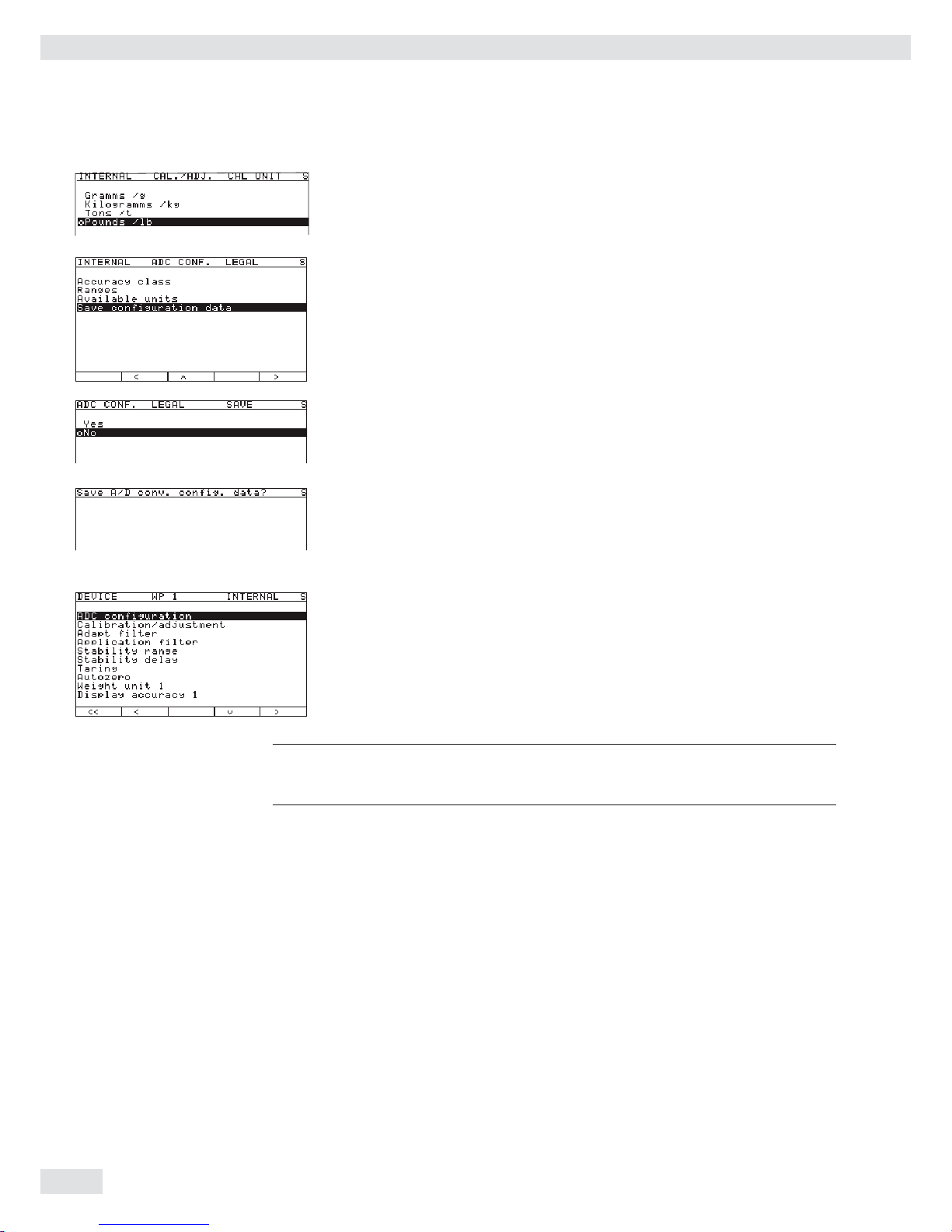
t To change the calibration/adjustment unit, select the unit using the “Q“ or “q“
soft key and confi rm using the “l“ soft key.
t Use the “o“ soft key to go back to the “Internal“ menu.
t Use the “Q“ soft key to select the “ADC confi guration“ menu item.
t Use the “O“ and “q“ soft key to select the “Save confi guration
data
“ menu item.
t To save the confi guration, use the “Q“ soft key to select “Yes“ and confi rm
using the “l“ soft key.
y The message “Function activated“ appears briefl y.
The program then returns automatically to the regular weighing mode.
To not save the confi guration:
t Press the “o“ soft key to exit the menu.
y The program returns to the next higher menu level.
To not save data:
t Press the “o“ soft key. The program returns to the WP1:Internal.
t Slide the menu access switch to the right (= “closed“ position) and reattach the
cap.
y The device is now in normal weighing mode.
h
Once ADC confi guration has been completed, an adjustment of the weighing
platform (calibration/adjustment and linearization) must be carried out (see
“Calibration/Adjustment without Weights“ and “External Linearization“).
30 Operating Instructions Combics Complete Scales
Confi guring Weighing Platforms

The displays depicted in the next two illustrations on the left show data from
a multi-interval scale confi gured as described above, or a similarly confi gured
multiple-range scale.
If the A/D converter was confi gured with a “Verifi able” data record, the lines for
display of metrological data (lines 1 and 2) show the data valid for use in legal
metrology.
The current range (e.g. R1) is displayed top left under the weighing point for
multiple-range scales.
ADC Configuration with Load Cell(s) Connected
Procedure: 1. Open the menu access switch, see “Analog/Digital Converter (ADC)
Confi guration.“
2. Activate the Service mode, see “Service Mode.“
3. Confi gure WP 1, see “Analog/Digital Converter (ADC) Confi guration.“
4. Set single-range mode, for example, see “Analog/Digital Converter (ADC)
Confi guration.“
5. Select the units, see “Analog/Digital Converter (ADC) Confi guration.“
6. Adjust without weights, see “Adjust without weights.“
7. Set/Delete the preload, see “Setting the Preload“ and “Deleting the Preload.“
Operating Instructions Combics Complete Scales 31
Confi guring Weighing Platforms

Entering Geographical Data for Use in Legal Metrology
Purpose Entering geographical data allows the external adjustment of weighing equipment
at a place (e.g. at the manufacturer or vendor‘s place of business) that is not the
same as the place of installation. If the weighing equipment is adjusted at the place
of installation, it is not necessary to enter geographical data.
The sensitivity of weighing equipment changes depending on the place of
installation as it is dependent on the on-site gravitational force – or, more precisely,
on gravitational acceleration. Saving geographical data makes it possible to change
the place of installation of the weighing equipment after external adjustment has
been carried out.
The adjustment of weighing equipment is valid at the place of installation and
within a specifi c tolerance zone. At 3000 e this zone extends ±100 km from the set
geographical latitude and ±200 m from the set elevation above sea level.
Installation Location in Germany An exception to this is the setting for “Germany (Zone D):” If during external
adjustment of weighing equipment within Germany the geographical data
– Geographical latitude: 51.00 degrees
– 513 m elevation above sea level
are entered, the weighing equipment can be used throughout Germany.
Gravitational acceleration for “Germany (Zone D)” is 9.810 m/s
2
. On delivery the
geographical data for “Germany (Zone D)” are entered in the output device.
It is recommended to use the geographical data settings for “Germany (Zone D)”
when adjusting and delivering the weighing equipment within Germany.
Entering exact geographical data will lead to a higher level of accuracy but will also
restrict the tolerance zone.
Setup Information – It is only possible to enter geographical data when the menu access switch is
open.
– When the Service mode is active, geographical data can be entered in the Setup
menu under “
WP 1“ for the fi rst weighing platform and “WP 2“ for the
second. Settings are made in the “Calibration/adjustment:
Geographical data: Input parameters
“ menu.
– You can enter either the “latitude“ (geographical latitude in degrees)
and “altitude“ (elevation in m above sea level) or the value for
gravitational acceleration “gravity.“
Gravitational acceleration takes precedence over the geographical latitude and
elevation of the location: If it has been entered, input fi elds for latitude and
elevation show the values “99999.99“ and “9999999“ respectively.
If only elevation and latitude have been entered, “0000000“ is displayed
for gravitational acceleration.
h
Then make sure that the geographical data for the adjustment location has been
entered correctly. If no external adjustment is carried out, enter the data for the
installation location. The data can be obtained from the relevant land registry or
Ordnance Survey.
32 Operating Instructions Combics Complete Scales
Confi guring Weighing Platforms

Procedure t Remove the cap.
t Slide the menu access switch to the left (= “open“ position).
If the device is part of a verifi ed weighing facility, this will only be possible if
the verifi cation seal is broken. The weighing equipment must then be verifi ed
again.
t Activate the Service mode, see “Service Mode.“
t Select weighing platform “WP 1“ in the “Device Parameters“
menu item.
t If the “Internal“ setting is not already activated (marked by “o“), select
the setting using the “Q“ or “q“ soft key and confi rm with “O.“
y The menu for the “WP-1 INTERNAL“ device parameters is displayed.
t Use the “Q“ or “q“ soft key to select and open the “CaCalibration/
adjustment
“ menu using “O.“
t Use the “Q“ or “q“ soft key to select and use “O“ to open the
“Geographical data“ menu.
t Use the “O“ soft key to confi rm “Input parameters.“
Entering Geographical Latitude and Elevation
t Use the “Q“ or “q“ soft key to select the corresponding input fi eld.
t Enter the number via the keypad and confi rm using the “l“ soft key.
y The next input fi eld is selected.
In this example, the geographical data are entered for the respective platform as a
value pair “Latitude“ and “Altitude.“ After this data was saved and the
scale returned to weighing mode, this pair of values is displayed again the next time
the display menu is opened. The input fi eld for gravitational acceleration is empty.
In this example, the value for gravitational acceleration is entered for the place of
installation. The fi elds “Latitude“ and “Altitude“ are invalid. The set
value is then re-displayed after it is saved and the input menu is re-opened. If you
exit the Setup menu and then open the Service mode, the set value for gravity is no
longer displayed.
Operating Instructions Combics Complete Scales 33
Confi guring Weighing Platforms

Entering Gravity
t Use the “Q“ or “q“ soft key to select the corresponding input fi eld.
t Enter gravity in m/s2 via the keypad and confi rm using the “l“ soft key.
Permissible value range:
9.700000 d < gravity 2 d < 9.900000
In the example shown here, the value for gravity has been changed.
The new value, 9.810000 m/s2 applies to the setting “Germany (Zone D).”
t Press the “o“ soft key to exit the Input menu.
t Use the “Q“ soft key to select the “Save parameters“ menu item.
t Use the “Q“ soft key to select “Yes“ and use the “l“ soft key to confi rm.
y The message “Data stored“ appears briefl y.
The program then returns to the “No“ display status.
t Press M or “oo“ to exit the Setup menu.
t Slide the menu access switch to the right (= “closed“ position) and reattach the
cap.
y The display goes out and the device restarts. Then weighing mode is active.
Adjusting Scales in Operating Mode
See also “Calibration and Adjustment“ in the chapter called “Operation“
t Open the Device parameters menu for the respective weighing platform,
(e.g. “WP 1:INTERNAL“).
– Open the “Calibration/adjustment“ submenu.
– „ CAL key function“ menu item:
Setting “Ext. cal./adj.: factory-def. wt.“
(factory setting).
– „ Cal/adj. sequence“ menu item:
Setting “Cal. then manual adj.“ (factory setting).
– „ Activate ext. adj.“ menu item
(not for a verifi able confi guration):
Setting “Activated“ (factory setting).
To display geographical data in the Device parameters menu, open the
“Operating parameters“ submenu.
Menu item “Display geogr. data > On“.
t Press ( to unload the scale.
34 Operating Instructions Combics Complete Scales
Confi guring Weighing Platforms

t Press J to start an external adjustment.
C.EXT.D
C.EXT.DEF.
y The display “C.EXT.D“ appears briefl y.
In the example, the altitude and latitude of the installation location are being entered.
Altitud
C.EXT.DEF.
y The display “Altitud“ appears briefl y.
y The altitude at the place of installation is displayed in meters above sea level - here, the
altitude for “Germany (Zone D).”
t Press J to confi rm the displayed value or press ( to cancel the adjustment.
Latitud
C.EXT.DEF.
y The display “Latitud“ appears briefl y.
y The geographical latitude of the place of installation is shown in degrees north or
degrees south - here the latitude setting for “Germany (Zone D).”
t Press J to confi rm the displayed value or press ( to cancel the adjustment.
y You are prompted to place the required weight on the platform (e.g.: 5.0 kg).
The subsequent steps for completing the calibration/adjustment are described in the
chapter entitled “Operation” under “Calibration and Adjustment.”
Operating Instructions Combics Complete Scales 35
Confi guring Weighing Platforms

If gravity is being entered instead of altitude and latitude, then “Gravity“ is
displayed for a brief time after “CAL.“
The entered value appears in m/s2, here for the “Germany (Zone D)“ setting.
t Press J to confi rm the displayed value or press ( to cancel the adjustment.
y You are prompted to place the required weight on the platform (e.g.: 5.0 kg).
The subsequent steps for completing the calibration/adjustment are described
in the chapter entitled “Operation” under “Calibration and Adjustment.“
t Slide the menu access switch to the right (= “closed“ position) and reattach the
cap.
y The display goes out and the device restarts. Then weighing mode is active.
If adjustment is carried out using a verifi able confi guration data record, the lines
for display of metrological data (lines 1 and 2) show the data valid for use in legal
metrology, if the menu access switch is closed. See also the chapter “Operation“,
“Confi guration for Use in Legal Metrology.“
36 Operating Instructions Combics Complete Scales
Confi guring Weighing Platforms

Entering Adjustment and Linearization Weights
Purpose Entering adjustment and linearization weights.
Procedure See also “Calibration and Adjustment“ in the chapter called “Operation“.
t Remove the cap.
t Slide the menu access switch to the left (= “open“ position).
t Activate the Service mode, see “Service Mode.“
t Select weighing platform “WP 1“ in the “Device Parameters“
menu item.
t If the “Internal“ setting is not already activated (marked by “o“), select
the setting using the “Q“ or “q“ soft key and confi rm with “O.“
y The menu for the “WP-1 INTERNAL“ device parameters is displayed.
t Use the “Q“ or “q“ soft key to select and open the “Calibration/
adjustment
“ menu using “O.“
t Use the “Q“ or “q“ soft key to select and use “O“ to open the “Parame-
ter for external weight
“ menu.
t The fi rst menu item “Cal/adj. wt.:“ (for selecting the user-defi ned
calibration weight), is also accessible without activating the Service mode.
The values for the linearization weights “Lin.-wt. 1“ to “Lin.-wt.
4
“ can, however, only be changed in the Service mode.
y The current values for the user-defi ned calibration weight and the
4 linearization weights are displayed.
In this example, the value for the external, user-defi ned adjustment weight is
changed to 6.000 kg.
t Press 6.000 and confi rm with the “l“ soft key.
y The “Lin.-wt. 1“ input fi eld is selected.
In this example, the value for linearization weight 1 is changed to 1.500 kg.
t Press 1.500 and confi rm with the “l“ soft key.
y The “Lin.-wt. 2“ input fi eld is selected.
t Enter or change all linearization weights in sequence as needed.
If you do not require all linearization positions, enter “0.000“ in the unused
fi elds to hide these lines in the display. Confi rm with the “l“ soft key after each
entry to move to the next input fi eld.
In the example shown here, four linearization weights have been entered
(1.5 kg, 3.0 kg, 4.5 kg and 6.0 kg).
When you close the input menu by pressing the “o“ soft key, the input values
are directly applied.
t Slide the menu access switch to the right (= “closed“ position) and reattach the
cap.
Operating Instructions Combics Complete Scales 37
Confi guring Weighing Platforms

Function Allocation of the allocation
for the J Key for Calibration/Adjustment
Purpose The J key is used for the calibration/adjustment function. Key settings can be
changed when the Service mode is activated:
Procedure t Remove the cap.
t Slide the menu access switch to the left (= “open“ position).
t Activate the Service mode, see “Service Mode.“
t Select weighing platform “WP 1“ in the “Device Parameters“
menu item.
t If the “Internal“ setting is not already activated (marked by “o“), select
the setting using the “Q“ or “q“ soft key and confi rm with “O.“
y The menu for the “WP-1 INTERNAL“ device parameters is displayed.
t Use the “Q“ or “q“ soft key to select and open the “Calibration/
adjustment
“ menu using “O.“
t Use the “O“ soft key to open the “Cal/adj. sequence“ menu.
t Use the “Q“ or “q“ soft key to select the “Cal. then manual
adj.
“ menu (factory setting) and confi rm with the “l“ soft key.
t Use the “o“ soft key to go to the next menu level.
t Use the “O“ soft key to open the “Activate ext. adj.“ menu.
t Use the “Q“ or “q“ soft key to select the “Activated“ menu item
(factory setting). Not for a verifi able confi guration.
t Geographical data is not displayed during calibration/adjustment (factory
setting).
To display geographical data in the Device parameters menu, open the
“Operating parameters“ submenu.
Menu item “Display geogr. data > On“.
38 Operating Instructions Combics Complete Scales
Confi guring Weighing Platforms

t Use the “O“ soft key to open the CAL key function“ menu.
y The “CAL key function“ submenu is displayed.
t Use the “Q“ or “q“ soft key to select the corresponding menu item and confi rm
with “l.“
y The menu item is marked by a circle “o.“
Note
The functions that can be confi gured in the “CAL key function“
submenu depends on the selected weighing platform and its confi guration data.
Functions that cannot be accessed are not displayed in the selection screen.
Important Note!
The function set in the “CAL key function“ menu is carried out in the
normal weighing mode because when you exit the Setup menu the Service mode is
deactivated. To perform the function on a digital weighing platform (such as an
IS platform), however, it must be carried out in Service mode.
t The procedure is as follows: after selecting the desired function and exiting
the Setup menu, reactivate Service mode again and then exit the Setup menu
immediately by pressing the M key or the “
oo“ soft key.
y The scale is now in Service mode without this being displayed.
t Trigger the previously set function using the J key.
C.EXT.D
C.EXT.DEF.
12
y The display shows “S_CAl:“ indicating that the scale is in Service mode.
t The corresponding menu item can be selected using the “Select“ soft key
and carried out using the J key.
t If you cancel the function using the ( key or by restarting the scale using
the e key, you will exit the Service mode.
External Calibration/Adjustment
with Factory-Defined Weight (Default Weight)
Configuration If not already selected (factory setting, marked by “o“ when active), select the
“CAL key function:Ext. cal./adj.; factory-
def. wt.
“ menu item (external adjustment with a factory-defi ned, standard
weight).
t Use the “Q“ or “q“ soft key to select this menu item and confi rm with “l.“
y The menu item is marked by a circle “o.“
Note:
The menu items “Ext. cal./adj.; factory-def. wt.“
(external adjustment with a factory-defi ned, standard weight), “Ext. cal./
adj.; user-defi ned wt.
“ (external adjustment with
a user-defi ned weight) and “Key blocked“ can also be accessed without
activating the Service mode.
Operating Instructions Combics Complete Scales 39
Confi guring Weighing Platforms

t Press e to turn off the device.
t Press e turn the device back on.
y The Sartorius logo is displayed briefl y, after which the device is in normal
weighing mode.
t Press ( to unload and zero the scale.
t Press J to start the external adjustment.
C.EXT.D
C.EXT.DEF.
y The display “C.EXT.D“ appears briefl y.
Note
If the display of geographical data (elevation and latitude or gravity) is activated,
this data is displayed and confi rmed each with a press of the J key (you can
cancel the calibration / adjustment process using the ( key).
See also “Entering Geographical Data for Use in Legal Metrology“ in this chapter.
Procedure y The target value of the required adjustment weight (5.000 kg in the example) is
displayed as a negative value.
t Place the required adjustment weight on the platform.
Note
If the calibration/adjustment sequence is set to automatic (“Calibration/
adjustment:Cal./adj. sequence:Cal., then auto
adjust
“ menu, see “Function Allocation of the allocation of the J Key for
Calibration/Adjustment“) and the adjustment weight consists of several pieces, then
they should be placed on the platform in series at short intervals.
When the weighing instrument has stabilized, the weight on the scale is accepted
as the calibration weight after a predefi ned interval, and the weighing instrument is
calibrated/adjusted with this weight.
The difference since the most recent span adjustment is not displayed; this value is
output only on GMP-compliant printouts.
y After a brief pause, the difference since the last span adjustment is displayed
(calibration).
Note
This display only appears for the “
Cal. then manual adj.“
setting (see previous note). If “Cal. then auto adj.“ is active, the
calibration/adjustment procedure cannot be cancelled.
To stop the procedure after calibration and before adjustment takes place, press the
( key (only if “Cal. then manual adj.“ is active).
t Press J to adjust the scale (only if “Cal. then manual adj.“
is active).
y At the conclusion of the calibration procedure, the calibration weight is
displayed as a positive value.
40 Operating Instructions Combics Complete Scales
Confi guring Weighing Platforms

--------------------
14.01.2010 13:50
Type CAW3P1-6DC-LCE
Ser.no. 12345678
Vers.no. 1.02.101110
BVers. 01-63-02
-------------------External calibration
Nom. + 5.000 kg
Diff. + 0.010 kg
External adjustment
Diff. + 0.000 kg
--------------------
14.01.2010 13:52
Name:
When calibration/adjustment is complete, the GMP-compliant printout shown on
the left is generated. If the adjustment procedure is canceled (only calibration is
performed), the last two lines, “External calibration” and “Diff. + 0.000 kg” are not
printed.
t Unload the scale.
t Press e to turn off the device.
t Press e turn the device back on.
y The Sartorius logo is displayed briefl y, after which the device is in normal
weighing mode.
3
If a serious operator error should occur during calibration (for example, if the menu
setting “Cal. then auto adj.“ is active and the wrong calibration
weight is placed on the scale), the scale might completely fail to stabilize, which
means it cannot show a zero point.
In this case, select the “
Adjust without weights“ menu and set the
mean sensitivity of the strain-gauge weighing beam to 2.0 mV/V.
Then re-adjust the scale.
See also “Adjust without weights.“
The zero point is only displayed for a verifi ed scale with d=e.
External Calibration/Adjustment
with a User-Defined Weight
Configuration Select the “CAL key function:Ext. cal./adj.; user-
def. wt.
“ menu item (external adjustment using a user-defi ned weight).
Note:
The menu items “Ext. cal./adj.; factory-def. wt.“
(external adjustment with a factory-defi ned, standard weight), “Ext. cal./
adj.; user-defi ned wt.
“ (external adjustment with a user-defi ned
weight) and “Key blocked“ can also be accessed without activating the
Service mode.
t Use the “Q“ or “q“ soft key to select this menu item and confi rm with “l.“
y The menu item is marked as set by a circle “o.“
t Enter the target value of the adjustment weight in the “Calibration/
adjustment
“ menu under “Parameter for external
weight
“ in the “Cal/adj. wt“ input fi eld.
Operating Instructions Combics Complete Scales 41
Confi guring Weighing Platforms

t Press e to turn off the device.
t Press e turn the device back on.
y The Sartorius logo is displayed briefly, after which the device is in normal
weighing mode.
t Press ( to unload and zero the scale.
t Press J to start the external adjustment.
C.EXT.U
C.EXT.USE.
y The display “C.EXT.U“ appears briefly.
Note
If the display of geographical data (elevation and latitude or gravity) is activated,
this data is displayed and confirmed each with a press of the J key (you can
cancel the calibration/adjustment process using the ( key). See also “Entering
Geographical Data for Use in Legal Metrology“ in this chapter.
Procedure t Press J to confirm the displayed value or press ( to cancel
the adjustment.
y The target value of the required adjustment weight (6.000 kg in the example) is
displayed as a negative value.
t Place the required adjustment weight on the platform.
If the calibration/adjustment sequence is set to “Cal. then auto adjust”, refer to
the note under “External Calibration/Adjustment with Factory-Defined Weight
(Default Weight).”
y After a brief pause, the difference since the last span adjustment is displayed
(calibration).
t If you only want to perform a calibration, press the ( key to cancel the
calibration/adjustment procedure.
t Press J to adjust the scale.
y At the conclusion of the calibration procedure, the calibration weight is dis-
played as a positive value.
--------------------
14.01.2010 13:50
Type CAW3P1-6DC-LCE
Ser.no. 12345678
Vers.no. 1.02.101110
BVers. 01-63-02
-------------------External calibration
Nom. + 6.000 kg
Diff. + 0.010 kg
External adjustment
Diff. + 0.000 kg
--------------------
14.01.2010 13:52
Name:
When calibration/adjustment is complete, the GMP-compliant printout shown on
the left is generated. If the adjustment procedure is canceled (only calibration is
performed), the last two lines, “External calibration” and “Diff. + 0.000 kg” are not
printed.
t Unload the scale.
t Press e to turn off the device.
t Press e turn the device back on.
y The Sartorius logo is displayed briefly, after which the device is in normal
weighing mode.
42 Operating Instructions Combics Complete Scales
Configuring Weighing Platforms

3
If a serious operator error should occur during calibration (for example, if the menu
setting “Cal. then auto adj.“ is active and the wrong calibration
weight is placed on the scale), the scale might completely fail to stabilize, which
means it cannot show a zero point.
In this case, select the “Adjust without weights“ menu and set the
mean sensitivity of the strain-gauge weighing beam to 2.0 mV/V.
Then re-adjust the scale.
See also “Adjust without weights.“
Internal Calibration/Adjustment
This function is available only if a digital weighing platform (for example, an IS
platform) is connected to WP 1, either as a second weighing platform or as the only
weighing platform without using the built-in A/D converter WP 1. The connection
can be made both via the COM1, COM2 or UNICOM interface with a corresponding
configuration as well as via the expansion PCBs for WP 1 or WP 2.
This function is also accessible without activating the Service mode.
Adjustment Without Weights
Purpose
In the Service menu, adjustment without weights can be carried out by entering the
characteristic data of the load cells.
3
Adjustment without weights may not be carried out on weighing equipment used
in legal metrology.
Setup information
– Adjustment without weights is only possible when the menu access switch is
open in the Service mode.
– The “Nominal load“ parameter must be entered in the “kg“ unit.
– The “Resolution“ parameter must be entered in the “kg“ unit and must
correspond to the scale interval “d“ entered for the ADC configuration.
– The “Sensitivity“ parameter is entered in “mV/V“ (see the data sheet for the
value).
h
These values are converted to internal quantities.
Once the ADC configuration data have been stored (by selecting the “Save
parameters
“ menu item), these parameters can no longer be read.
Operating Instructions Combics Complete Scales 43
Configuring Weighing Platforms

Procedure t Remove the cap.
t Slide the menu access switch to the left (= “open“ position).
t Activate the Service mode, see “Service Mode.“
t Select weighing platform “WP 1“ in the “Device Parameters“
menu item.
t If the “Internal“ setting is not already activated (marked by “o“), select
the setting using the “Q“ or “q“ soft key and confirm with “O.“
y The menu for the “WP-1 INTERNAL“ device parameters is displayed.
t Use the “Q“ or “q“ soft key to select and open the “Calibration/
adjustment
“ menu using “O.“
t Use the “Q“ or “q“ soft key to select and use “O“ to open the “Adjust
without weights
“ menu.
t Use the “O“ soft key to open the “Input parameters“ menu.
y The Input menu is displayed.
Enter the nominal capacity and resolution of the load cells in kg and the
sensitivity of the load cells in mV/V in the corresponding input fields.
The maximum capacity is usually less than the value to be entered in the
“Adjust without weights“ menu for the nominal capacity of
the load cell, as load cells carry additional weight (e.g., a weighing platform).
44 Operating Instructions Combics Complete Scales
Configuring Weighing Platforms

If the weighing platform has multiple load cells, multiply the nominal capacity
accordingly.
Example:
The weighing platform has 4 load cells each at 50 kg.
The nominal capacity is 4 x 50 kg = 200 kg.
In the example shown here, the weighing platform consists of one load cell with a
maximum capacity of 10 kg.
t Press 10.00 and confirm with the “l“ soft key.
y The “Resolution“ input field is selected.
The smallest digit “d“ is entered in this field in “kg“. The value must correspond
to the “D“ entry in “ADC configuration: Standard:
Ranges: Single-range mode
.“
In the example, this should be d = 0.002 kg.
t Press 0.002 and confirm with the “l“ soft key.
y The “Sensitivity 1“ input field is selected.
If the weighing platform has multiple load cells, enter the sensitivity either
– under “Sensitivity 1“ … “Sensitivity 4“ as an individual
value or
– under “Sensitivity 1“ as an average value.
If an average value is entered for all cells, or if fewer than 4 load cells are
present, enter “0“ in the remaining fields. Range of permitted values: 0.01…5
mV/V.
t Press 1.944, e.g. to enter a sensitivity of 1.944 mV/V.
t Confirm using the “l“ soft key.
y The “Sensitivity 2“ input field is selected.
t Either enter a value or set all remaining input fields to “0.“
t Confirm each using the “l“ soft key.
t Press the “o“ soft key to exit the menu.
t Use the “q“ soft key to select the “Save parameters“ submenu.
t To save the configuration, select “Yes“ and confirm using the l soft key.
In the first line of the display, the message “Data stored“ is shown
briefly.
Then the program then returns to the “No“ display status.
t Use the “o“ to return to the next menu level.
t Press M or “oo“ to exit the Setup menu.
t Slide the menu access switch to the right (= “closed“ position) and reattach the
cap.
y The display goes out and the device restarts. Then weighing mode is active.
Operating Instructions Combics Complete Scales 45
Configuring Weighing Platforms

Function Allocation of the J Key for Linearization and Setting/
Deleting the Preload
Purpose The J key is normally used for the calibration/adjustment function.
The following additional functions can be allocated to the key when the Service
mode is activated:
– External linearization with default weights
– External linearization with entered linearization weights
– Internal linearization (for external IS platforms only)
– Set preload
– Delete preload
3
Once linearization has been completed, or after a preload has been set or deleted
the function of the J key must be reallocated back to its original function in the
Setup menu, e.g. external calibration/adjustment with default weights.
Procedure t Remove the cap.
t Slide the menu access switch to the left (= “open“ position).
t Activate the Service mode, see “Service Mode.“
t Select weighing platform “
WP 1“ in the “Device Parameters“
menu item.
t If the “Internal“ setting is not already activated (marked by “o“), select
the setting using the “Q“ or “q“ soft key and confirm with “O.“
y The menu for the “WP-1 INTERNAL“ device parameters is displayed.
t Use the “Q“ or “q“ soft key to select and open the “Calibration/
adjustment
“ menu using “O.“
y The “CAL key function“ submenu is displayed.
t Use the “Q“ or “q“ soft key to select the corresponding menu item and confirm
with “l.“
y The menu item is marked by a circle “o.“
Note
The functions that can be configured in the “CAL key function“
submenu depends on the selected weighing platform and its configuration data.
Functions that cannot be accessed are not displayed in the selection screen.
Note
The function set in the “CAL key function“ menu is carried out in the
normal weighing mode because when you exit the Setup menu the Service mode is
deactivated. To perform the function on a digital weighing platform (such as an IS
platform), however, it must be carried out in Service mode.
t The procedure is as follows: after selecting the desired function and exiting
the Setup menu, reactivate Service mode again and then exit the Setup menu
immediately by pressing the M key or the “oo“ soft key.
y The scale is now in Service mode without this being displayed.
t Trigger the previously set function using the J key.
y The display shows “S_CAl:“ indicating that the scale is in Service mode.
t The corresponding menu item can be selected using the “Select“ soft key
and carried out using the J key.
t If you cancel the function using the ( key or by restarting the scale using
the e key, you will exit the Service mode.
46 Operating Instructions Combics Complete Scales
Configuring Weighing Platforms

External Linearization with the Factory-Defined
Weight (Default Weights)
Setup Information – This function is accessible only if the software and the functionality of the
connected weighing platform permit this operation.
– External linearization when weighing in legal metrology is only possible when
the menu access switch is open.
– The J key must be assigned the “External linearization“ function, see
“Function Allocation of the J Key for Linearization and Setting/Deleting the
Preload.“
– Activating the display of geographical data has no effect on this function.
3
Once linearization has been completed, the J key must be reallocated back to
its original function in the Setup menu, e.g. external calibration/adjustment with
default weights.
Procedure t For scales used in legal metrology, slide the menu access switch to the left
(= “open“ position).
y The display goes out and the device restarts. Then weighing mode is active.
t Press ( to unload and zero the scale.
t Press J to start the external linearization.
y The display “L.EXT.D“ appears briefly.
Additional steps are explained in “External Linearization with User-Defined
Weights.“
Operating Instructions Combics Complete Scales 47
Configuring Weighing Platforms

External Linearization with User-Defined Weights
Setup Information – This function is accessible only if the software and the functionality of the
connected weighing platform permit this operation.
– External linearization when weighing in legal metrology is only possible when
the menu access switch is open.
– The J key must be assigned the “External linearization“ function,
see “Function Allocation of the J Key for Linearization and Setting/Deleting
the Preload.“
– Activating the display of geographical data has no effect on this function.
3
Once linearization has been completed, the J key must be reallocated back
to its original function in the Setup menu, e.g. external calibration/adjustment with
default weights.
Configuration t Set the linearization weights, see “Entering Adjustment and Linearization
Weights.“
Procedure t For scales used in legal metrology, slide the menu access switch to the left
(= “open“ position).
y The display goes out and the device restarts. Then weighing mode is active.
t Press ( to unload and zero the scale.
t Press J to start the external linearization.
y The display “L.EXT.U“ appears briefl y.
y After approx. 2 seconds, the target value for linearization weight 1 is shown as
a negative value on the display (in example shown here, 1.500 kg) .
t Place the required linearization weight 1 on the platform.
t Press J to apply linearization weight 1 or press ( to cancel the
linearization function.
y After a short time the difference between the measured value and the true
weight of the sample will be displayed.
48 Operating Instructions Combics Complete Scales
Confi guring Weighing Platforms

--------------------
14.01.2010 13:00
Type CAW3P1-6DC-LCE
Ser.no. 12345678
Vers.no. 1.02.101110
BVers. 01-63-02
-------------------Linearization
Wt.1 + 1.500 kg
Wt.2 + 3.000 kg
Wt.3 + 4.000 kg
Wt.4 + 6.000 kg
completed
--------------------
14.01.2010 13:02
Name:
t Press J to apply linearization weight 1 or press ( to cancel the
linearization function.
y After the linearization weight 1 has been saved you will be prompted to place
the second linearization weight on the weighing pan.
t Repeat the procedure for all required linearization weights.
y After the last linearization weight has been saved you will be prompted to
remove any load from the weighing pan.
t Remove all linearization weights from the weighing platform.
y The zero point is applied automatically after a brief time. The indicator
automatically switches to weighing operation.
When linearization is complete, the GMP-compliant printout shown on the left
is generated.
t Slide the menu access switch to the right (= “closed“ position).
Operating Instructions Combics Complete Scales 49
Configuring Weighing Platforms

Set preload
Setup Information – Setting the preload when weighing in legal metrology is only possible when the
menu access switch is open.
– The J key must be assigned the “Set preload“ function, see “Function
Allocation of the J Key for Linearization and Setting/Deleting the Preload.“
– Activating the display of geographical data has no effect on this function.
3
Once the preload has been set, the J key must be reallocated back to its original function
in the Setup menu, e.g. external calibration/adjustment with default weights.
Procedure t For scales used in legal metrology, slide the menu access switch to the left (= “open“
position).
t Press e turn the device back on.
y The Sartorius logo is displayed briefly, after which the device is in normal weighing
mode.
t Press ( to unload and zero the scale.
y Display after the scale has been zeroed.
t Place the preload weight on the weighing platform.
t Press J to start “Set preload.“
y The display “SET PREL“ appears briefly.
After a short period of time the preload will be applied and the indicator will
automatically switch back to weighing mode.
After the “Set Preload” operation has been completed, the scale is zeroed.
--------------------
14.01.2010 13:50
Type CAW3P1-6ED-LCE
Ser.no. 12345678
Vers.no. 1.02.101110
BVers. 01-63-02
-------------------Set preload
completed
--------------------
14.01.2010 13:52
Name:
When the “Set preload“ function is complete, the GMP-compliant printout shown on
the left is generated.
t Slide the menu access switch to the right (= “closed“ position).
50 Operating Instructions Combics Complete Scales
Configuring Weighing Platforms

Delete preload
Setup Information – Deleting the preload when weighing in legal metrology is only possible when
the menu access switch is open.
– The J key must be assigned the “Delete preload“ function, see “Function
Allocation of the J Key for Linearization and Setting/Deleting the Preload.“
– Activating the display of geographical data has no effect on this function.
3
Once the preload has been deleted, the J key must be reallocated back to its
original function in the Setup menu, e.g. external calibration/adjustment with
default weights.
Procedure t For scales used in legal metrology, slide the menu access switch to the left
(= “open“ position).
t Press e turn the device back on.
y The Sartorius logo is displayed briefl y, after which the device is in normal
weighing mode.
t Remove the preload weight from the weighing platform.
y The display shows the removed preload weight as a negative value.
t Press J to start “Delete preload.“
y The display “CLR PREL“ appears briefl y.
After a short period of time the preload will be deleted and the indicator will
automatically switch back to weighing mode.
After the “Delete Preload” operation has been completed, the scale is zeroed.
--------------------
14.01.2010 13:50
Type CAW3P1-6DC-LCE
Ser.no. 12345678
Vers.no. 1.02.101110
BVers. 01-63-02
-------------------Delete preload
completed
--------------------
14.01.2010 13:52
Name:
When deleting the preload is complete, the GMP-compliant printout shown on the
left is generated.
t Slide the menu access switch to the right (= “closed“ position).
Operating Instructions Combics Complete Scales 51
Confi guring Weighing Platforms

52 Operating Instructions Combics Complete Scales
Operating Design
Weighing Mode Operating Design
Labeled Keys
Some keys have a second function, activated by pressing and holding the key for
over 2 seconds. Whether a function is available depends on the indicator operating
state and operating menu settings.
e On/Off key
y standby is displayed in Standby mode.
n If a second weighing platforms is connected, this key toggles the display between
the two readouts.
( – Press briefly: Zero
– Press briefly: cancels calibration/adjustment
– Press longer than 2 seconds: displays the adjustment/configuration counter
) Tare the scale: press briefly.
k Displays the second weight unit or SQmin (depending on the settings, see
“Operation,“ “SQmin Function“).
J Starts calibration or adjustment.
p – For printing:
Press briefly.
– Prints GMP footer:
Press longer than 2 seconds.
K Toggles unit between normal and 10-fold higher resolution.
L Toggles the display between
gross value (net value plus tare) and
net value (gross value minus tare).
c – Quits an application or deletes an input character:
Press the key less than 2 seconds.
– Deletes the entire input string:
Press the key longer than 2 seconds.
Operating
Design
You can use the Combics 3 to
record weight values from 1 to
3 weighing platforms, calculate
and display weight values through
application programs, and assign
IDs to the samples weighed.
Configure the indicator first, using
the Setup menu for the desired
application program (printer
settings, etc.). Then you can begin
weighing.
When a key is pressed that does
not have an active operating mode
function, an acoustical signal
(double beep) sounds and the
message “——-—“ is displayed for
2 seconds. The display then
returns to the previous screen
content.

D Toggles to the Info mode:
Press longer than 2 seconds.
R Product data memory:
Saves initialization and user data (product and tare values).
The product data memory can store over 400 product and tare values.
M Opens/Exits the Setup program
1, 2, 3 ... ., 0 Enters numbers, letters and other characters.
a Toggles between numeric and alphabetic input.
Soft keys
ID
F5 F4 F3 F2 F1
The functions of active soft keys are indicated by symbols and abbreviations in the
last line on the display.
Abbreviation examples:
– ID: ID list
– DELETE: Delete entry
Symbols used for soft key functions:
oo: Return to initial state
o: Next higher menu level
O: Show items under selected entry
Q: Scroll up in the input/output window
q: Scroll down in the input/output window
l: Set the selected menu parameter
Numeric Input via the Keypad
t To enter numbers (one digit at a time):
Press 0, 1, 2 … 9
t To save input:
press the corresponding key.
For example, press ) to save manual tare input.
Text Input via the Keypad
t Press the a key.
y “ABC“ is displayed.
t For example, press the 4 key.
y The corresponding letter is displayed. The fl ashing cursor marks the fi rst letter.
t Press the key as many times needed to select the desired letter.
t Press the F1 soft key (l) or wait 2 seconds.
y The selected letter appears on the display.
Operating Instructions Combics Complete Scales 53
Operating Design

Entering Spaces via the Keypad
t Press the a key.
y “ABC“ is displayed.
t Press the 0 key.
y The corresponding selection is displayed. The fl ashing cursor marks the space.
t Press the F1 soft key (l) or wait 2 seconds.
y The space appears on the display.
Special Character Input via the Keypad
t Press the a key.
y “ABC“ is displayed.
t Press the 1 key.
y The corresponding character selection is displayed. The fl ashing cursor marks
the fi rst character.
t Press the F1 soft key (l) or wait 2 seconds.
y The special character appears on the display.
Deleting characters
t Press c.
Deleting entire input string
t Press the F4 soft key (ESC).
Saving Input
t Enter a value.
t Press the corresponding soft key (e.g. 1.ID to defi ne an identifi er).
54 Operating Instructions Combics Complete Scales
Operating Design

Saving Settings in Weighing Mode
You can specify the save type used in the Application Parameters
Setup menu.
By default, all application parameters saved (e. g., reference values) remain in
memory and are available when
– the device has been switched off and then on again
– you return to the originally selected application from a second one (e. g., when
you switch from Averaging back to Counting all parameters saved for Counting
are available).
Applying the Tare Weight
To save the weight on the weighing platform as a tare weight:
t Place the tare object on the weighing platform.
t Press ).
y The value is applied as the tare value.
Input Through the Digital Control Port
You can connect a remote hand switch or foot switch to the input control
line, for use with all application programs. The following functions can be
assigned in the Setup menu Device Parameters:Control I/O
Ports:Universal Switch Key:
– Off – Zeroing key
– Print key – On key
– Print key >2 sec – CF key
– Tare key – F1 function key
– ISO test key – Appl. toggle key
– Fn key function – 10x higher resolution key
– WP toggle key – Net/gross value key
– Combined zero/
tare function
Operating Instructions Combics Complete Scales 55
Operating Design

Display in Weighing Mode
Weighing Mode: Display of Measured and Calculated Values
Lines for metrological data
Bar graph
Text lines
Soft key labels
Line for measured values
Plus or minus sign
Stability
Battery symbol
Application symbol
Unit
Tare memory
Calculated values
Info/Status line
The display is divided into several sections.
Lines for metrological data The following parameters are shown here:
Max Maximum capacity (upper weighing range limit) of the active weighing platform
Min Minimum capacity (lower weighing range limit) of the active weighing
(verified models only)
e Verification scale interval of the active weighing platform (verified models only)
d Smallest display digit of the active weighing platform
R1 R2 Display of the current weighing range of the active weighing platform
(with multiple range scale connected)
Symbols and Their Meaning
b The Busy symbol appears when the scale is processing a function activated
by pressing a key.
+ - The plus or minus sign of the weight or other measured value
o Verified models only:
Identifies “zero” as a weight value (after the scale or the active weighing platform
has been zeroed)
Measured Value Line/Calculated Values
5.23r The current weight value (on verified scales or platforms with e = d, the last digit is
bordered for identification)
20 A calculated value when using an application program, such as Counting or
Weighing in Percent
Unit and Stability
g The current weight unit (e.g. “g“)
pcs Identifies additional characteristics (e.g. “pieces“ for the “Counting“ application)
When the weighing system reaches stability, the weight unit or calculation unit is
displayed here.
56 Operating Instructions Combics Complete Scales
Operating Design

Data in Tare Memory, Calculated Value,
Identification of the Active Weighing Platform
when More Than One Platform is Used
! Identification of calculated values (values not used in legal metrology)
B/G NET Indicates gross value or net value (data in tare memory)
PT Indicates manual tare input (using a barcode scanner) when viewing tare
information.
WP1 Display of the active weighing platform when 2 platforms are connected.
The display flashes for a ISO Cal adjustment prompt if WP 1 is an IS-weighing
platform.
WP When the timer is active (Setup:Device Parameters:
Operating Parameters:Timer
), the symbol flashes to indicate
that the set time has halfway expired.
Application, Printing and Battery Symbols
S Printing in progress
T GMP-compliant printout active
, Battery status: ‘Battery fully charged’ or ‘Battery empty’
Bar Graph
The bar graph shows the percentage of the weighing platform’s capacity that is
“used up” by the load on the scale (gross value).
0% Lower load limit
100% Upper load limit
The following symbols indicate tolerance levels for checkweighing:
Bar graph showing 10% intervals
Minimum for “checkweighing“
Target value for “checkweighing“
Maximum for “checkweighing“
Application Symbols
A Symbol for the Counting application
Y Symbol for “checkweigher“ counting down to “zero“
L H W M B A D Symbols for the Totalizing, Checkweighing, Classification, Net-total Formulation,
Weighing in Percent, Counting (with or without reference sample updating) and
Neutral Measurement application programs.
For details on the symbols, please see the chapters for the respective application
programs in the manual.
Text Lines The text lines show operator support information, such as IDs and user guidance
prompts.
Soft Key Line This line shows the abbreviations or symbols that indicate soft key functions.
Operating Instructions Combics Complete Scales 57
Operating Design

LEDs
LEDs indicate
– whether the weight exceeds tolerance limits for checkweighing
– the weight value classification for the Classification application
Error Codes
– If a key is inactive, “-------” and/or “No function”” is displayed
(2 sec.) and an acoustic signal (double- beep) is emitted
– Temporary errors are displayed for 2 seconds in the measured value/result
line via an error code (e .g.,
INF 09); fatal errors (e .g., ERR 101) are
displayed continuously until cleared via a restart.
Error codes are described in detail in “Data Interfaces“ in “Error Codes.“
Menu Operating Design
Operating Example: Setup:Device parameters:
WP 1:Internal:Adapt filter
o Marks the current menu setting
Configuring parameters:
t Soft key “Q“ or “q“: Parameter settings
t Soft key “l“: Confirm parameter
t M or “oo“: Exit Setup menu
Menu display
Display Mode for Configuration and Information (Setup)
Status line
Input/output window
Soft key labels
The display is divided into three sections.
Status Line
Indicates the function of the current screen page. In the Setup program, this line
shows the “path” to the data displayed.
Input and Output Window
For input and display of detailed information; e.g., for the selected application.
Selected items are displayed inversely (white letters on a black background).
Soft key labels
See the description in this section.
Saving Menu Settings
The parameters selected in the menu remain saved when you switch to weighing
mode or turn off the device.
You can block access to the Device parameters menu by requiring a password to
prevent unauthorized or accidental setting changes (see also “Setting up Password
Protection“).
58 Operating Instructions Combics Complete Scales
Operating Design

Configuration
You can confi gure the indicator by selecting parameters in the Setup menu.
These are divided into the following groups (menu level 1), menu structure see
section the “Setup Overview (Parameters)“ section
– Application parameters
– Fn key function
– Device parameters
– Info (device-specifi c information)
– Language
When used in legal metrology, not all parameters can be accessed. The indicator
only displays parameters that can be selected.
Factory-set parameters are identifi ed by an “o” in the list starting on the next page.
Setting the Language
You can choose from the following languages for displaying information:
– Deutsch
– English (factory setting)
– U.S. mode
– Français
– Italiano
– Español
Example: Selecting “U.S. Mode“ for the language
t Press e to turn on the device.
t Press M.
y The menu appears on the display.
t Press the “q“ soft key several times to select the “Language“ line.
t Press the “O“ soft key.
y The language selection appears on the display.
t Press the “Q“ soft key to select the “U.S. mode“ line.
Operating Instructions Combics Complete Scales 59
Operating Design

t Press the l soft key to save the setting.
y The setting selection “o“ moves to “U.S. mode.“
t Press M or oo to exit the Setup menu.
Setting up Password Protection
t Press e to turn on the device.
t Press M.
y The menu appears on the display.
t Press the “q“ soft key several times to select the “Device
parameters
“ line.
t Press the “O“ soft key.
t Press the “q“ soft key several times to select the “Password“ line.
y The input line appears on the display.
t Enter numbers and/or letters via the keypad, see “Numeric Input via the
Keypad“ and “Letter Input via the Keypad.“
t Press the “l“ soft key to save the setting.
t Press M or “oo“ to exit the Setup menu.
60 Operating Instructions Combics Complete Scales
Operating Design

Setting up Password Protection
t Press e to turn on the device.
t Press M.
y The menu appears on the display.
t Press the “q“ soft key several times to select the “Device
parameters
“ line.
t Press the “O“ soft key.
y The Access window appears on the display.
t Enter the password via the keypad, see “Numeric Input via the Keypad“ and
“Letter Input via the Keypad.“
t Press the “l“ soft key.
y The device selection appears on the display.
t Press the “q“ soft key several times to select the “Password“ line.
y The input line appears on the display.
t Press c several times to delete the password.
t Press the “l“ soft key to save the delete.
If not yet saved, the process can be canceled using the “ESC“ soft key.
t Press M or “oo“ to exit the Setup menu.
Operating Instructions Combics Complete Scales 61
Operating Design

Printing Parameter Settings
Example: Maximum 20 characters per line.
--------------------
12.01.2010 09:46
Type CAIS3
Ser.no 12345678
Vers. 1.02.101110
BVers. 01-63-02
-------------------SETUP
DEVICE
------------------- WP 1
Internal
WP 2 off
COM1
Data communcations
SBI
Baud rate
1200 Baud
Parity
Odd
Number of Stop bits
1 Stop bit
Handshake mode
Hardware 1-char
Number of data bits
7 Bit
Data output
Printout printer 1
etc.
62 Operating Instructions Combics Complete Scales
Operating Design

Setup Overview (Parameters)
o = Factory settings
W = User-defined setting
Setup
Application parameters: Please refer to the “Basic Application Programs” manual
Fn key function
o Off
Unit conversion
SQMIN (only possible when the display has been turned on in the “Device parameters:SQMin“ menu item)
Device parameters
WP 1
RS-232 1)
SBI standard
SBI verifiable
o IS-232
ADC-232
RS-485 1)
o IS-485
ADC-485
Internal
Calibration/Adjustment
CAL key function
o Ext. cal./adj.; factory-def. wt.
Ext. cal./adj.; user-defined wt.
Key blocked
Cal./adj. sequence
Cal. then auto adjust
o Cal. then manual adjust
isoCAL function
3
)
o Off
Adjustment prompt
Activate external adjustment 2)
o Activated
Deactivated
Parameter for external weight
Cal./adj. weight:
Calibration/adjustment unit
Grams /g
Kilograms /kg
Tons /t
Pounds /lb
Adapt filter
Min. vibration
o Normal vibration
Strong vibration
Extreme vibration
Application filter
o Final readout
Filling mode
Low filtering
Without filtering
Stability range
1/4 digit
1/2 digit
1 digit
2
)
o 2 digits 2)
4 digits 2)
8 digits 2)
1
) Equipment version: – then blocked internally
2
) Not available on devices verified for use in legal metrology
3
) Only when operated with Sartorius IS weighing platforms or an external ADC
Operating Instructions Combics Complete Scales 63
Operating Design

Device Parameters
WP 1
Internal
Stability delay
Without delay
o Short delay
Average delay
Long delay
Taring 1)
Without stability
o After stability
Autozero
o On
Off
Weight unit 1 2)
User-definable / o (factory setting: grams) 1)
Grams /g
o Kilograms / kg
Carats / ct 1)
Pounds / lb 1)
Ounces / oz v)
Troy ounces / ozt 1)
Hong Kong taels / tlh 1)
Singapore taels / tls 1)
Taiwan taels / tlt 1)
Grains / GN 1)
Pennyweights / dwt 1)
Milligrams / mg 1)
Parts per pound / lb 1)
Chinese taels / tlc 1)
Mommes / mom 1)
Austrian carats / K 1)
Tola / tol 1)
Baht / bat 1)
Mesghal / MS 1)
Tons / t
lb / oz
Display accuracy 1
o All digits
One less for wt. change
Index +1 1)
Index +2 1)
One less 1)
Zero range
1 percent/max. cap.
o 2 percent/max. cap.
Zero at power on
2 percent/max. cap.
5 percent/max. cap.
o 10 percent/max. cap.
Tare/zero at power on:
o On
Off
Only zero at power on
1
) Not available on devices verified for use in legal metrology
2
) Depends on weighing platform type
64 Operating Instructions Combics Complete Scales
Operating Design

Device Parameters
WP 1
Internal
Weight unit 2
2
)
User-definable / o (factory setting: grams)
1
)
o Grams / g
Kilograms / kg
Carats / ct
1
)
Pounds / lb
1
)
Ounces / oz
1
)
Troy ounces / ozt
1
)
Hong Kong taels / tlh
1
)
Singapore taels / tls
1
)
Taiwan taels / tlt
1
)
Grains / GN 1)
Pennyweights / dwt
1
)
Milligrams / mg 1)
Parts per pound / / lb
1
)
Chinese taels / tlc
1
)
Mommes / mom
1
)
Austrian carats / K
1
)
Tola / tol
1
)
Baht / bat
1
)
Mesghal / MS
1
)
Tons / t
lb / oz
Display accuracy 2
o All digits
One less for wt. change
Index +1
1
)
Index +2
1
)
One less
1
)
Factory settings: weighing parameters only
Yes
o No
1
) Not available on devices verified for use in legal metrology
2
) Depends on weighing platform type
Operating Instructions Combics Complete Scales 65
Operating Design

Device Parameters
WP 1
Internal
Weight unit 3
2
)
User-definable / o (factory setting: grams)
1
)
o Grams / g
Kilograms / kg
Carats / ct
1
)
Pounds / lb
1
)
Ounces / oz
1
)
Troy ounces / ozt
1
)
Hong Kong taels / tlh
1
)
Singapore taels / tls
1
)
Taiwan taels / tlt
1
)
Grains / GN 1)
Pennyweights / dwt
1
)
Milligrams / mg 1)
Parts per pound / lb
1
)
Chinese taels / tlc
1
)
Mommes / mom
1
)
Austrian carats / K
1
)
Tola / tol
1
)
Baht / bat
1
)
Mesghal / MS
1
)
Tons / t
lb / oz
Display accuracy 3
o All digits
One less for wt. change
Index +1
1
)
Index +2
1
)
One less
1
)
Factory settings: weighing parameters only
Yes
o No
Off
COM 1 (when the WP is assigned to this interface)
COM 2 (when the WP is assigned to this interface)
UNICOM (when the WP is assigned to this interface)
Device
parameters WP 2
RS-232
3
) o ADC-232 similar to “Internal“ menu for WP 1
RS-485
3
) o ADC-485 similar to “Internal“ menu for WP 1
o Off
COM 1 similar to WP 1
COM 2 similar to WP 1
UNICOM similar to WP 1
1
) Not available on devices verified for use in legal metrology
2
) Depends on weighing platform type
3
) Equipment version
66 Operating Instructions Combics Complete Scales
Operating Design

Device Parameters
COM 1
o Off
WP 3
o RS-232
SBI standard (9600 baud)
SBI verifiable (9600 baud)
o IS-232
1
)
ADC-232
1
)
Data communications
o SBI
Baud rate
150 baud
300 baud
600 baud
o 1200 baud
2400 baud
4800 baud
9600 baud
19200 baud
Parity
Space
1
)
o Odd
Even
None
2
)
Number of stop bits
o 1 stop bit
2 stop bits
Handshake mode
Software handshake
o Hardware 1-char
Number of data bits
o 7 bits
8 bits
Data output
On request, without stability
o On request, after stability
Automatic, without stability
o 1 display update
2 display updates
10 display updates
100 display updates
On request, without stability
o 1 display update
2 display updates
10 display updates
100 display updates
Printout printer 1
Printout printer 2
1
) Not with 8 data bits
2
) Not with 7 data bits
Operating Instructions Combics Complete Scales 67
Operating Design

Device Parameters
COM 1
Data communications
o SBI
Line format
For raw data (16 characters)
o For other apps. (22 characters)
Sign format
Do not output + sign
o Output + sign
Factory setting
Yes
o No
XBPI RS-232
SMA
Baud rate
150 baud
300 baud
600 baud
o 1200 baud
2400 baud
4800 baud
9600 baud
19200 baud
Parity
Space
1
)
Odd
Even
o None
2
)
Number of stop bits
o 1 stop bit
2 stop bits
Handshake mode
Software handshake
o Hardware 1-char
Number of data bits
o 8 bits
1
) Not with 8 data bits
2
) Not with 7 data bits
68 Operating Instructions Combics Complete Scales
Operating Design

Device Parameters
COM 1
Printer 1
1
)
YDP20
Baud rate
o 1200 baud
2400 baud
4800 baud
9600 baud
19200 baud
Parity
Space
o Odd
Even
Number of stop bits
o 1 stop bit
2 stop bits
Handshake mode
Software handshake
o Hardware 1-char
YDP14IS
o Strip
Label
Universal
Baud rate
150 baud
300 baud
600 baud
1200 baud
2400 baud
4800 baud
o 9600 baud
19200 baud
Parity
Odd
Even
o None
Number of stop bits
o 1 stop bit
2 stop bits
Handshake mode
o Software handshake
Hardware, 1-char
Number of data bits
o 8 bits
o YDP14IS
o Strip
Label
Label, manual form feed
Printer 2
1
) Similar to printer 1
1
) Max. 2 printers can be configured
Operating Instructions Combics Complete Scales 69
Operating Design

Device Parameters
COM 2 similar to COM 1
UNICOM (optional interface)
o Off
WP 3
o RS-232
SBI standard (9600 baud)
SBI verifiable (9600 baud)
o IS-232
1
)
ADC-232
1
)
RS-485
o IS-485
1
)
ADC-485
1
)
Data communications
o SBI similar to COM 1
xBPI-232 similar to COM 1
xBPI-485 address 0 to 31 can be selected
SMA similar to COM 1
Profibus address: 0 to 126 can be selected,
factory setting: 126
Ethernet
Printer 1
1
) Similar to COM 1
Printer 2 1) Similar to COM 1
Analog output
Analog output: value
o Net value
Gross value
Analog Out: Error Signal
o High level (20 mA)
Low level (0/4 mA).
When menu is open or during
calibration
(0/4 mA) on this interface.
Analog output: mode
o Zero to maximum capacity
Minimum/Maximum values
Analog Out: Data Output Min./Max.
o Min. (0/4 mA) input in kg
Max. (20 mA) input in kg
1
) Not with 8 data bits
70 Operating Instructions Combics Complete Scales
Operating Design

Device Parameters
I/O control
Input ports
Universal switch key
Off
p Print key
p Print key - long
) Tare key
o J ISO-Test key
k Fn key
n WP toggle key
Comb. tare/zero function
(zero if possible, otherwise tare.)
( Zero key
e On key
c CF key
v F1 function key
D Toggle between applications
K 10x higher resolution key
L Net/gross value key
Level internal output ports
o All active low
All active high
Bar code
o Reference
Tare
ID1
Input
Input without activating function
External keyboard
Config. printout
Headers
Line 1:
Line 2:
ID codes
ID1:
ID2:
ID3:
ID4:
ID5:
ID6:
ISO/GLP/GMP printout
o Off
For several application results
Date/time
o Date with time
Date only
Once at stability
o Off
On
FlexPrint
o Off
On
Operating Instructions Combics Complete Scales 71
Operating Design

Device Parameters
Config. printout
Printer 1
Number of printouts
o 1 printout
2 printouts
Indiv.: Printout f. app./weighing
List <-> Selection
Gross (G#) Space line
Tare ------- Net (N) Form feed
Space line Date/time
Time
GMP header
GLP footer
Transaction no.
ID1…ID6
Tare 2 (T2/PT2)
Header line 1
Header line 2
Scale ser. no.
Product no.
Product name
Product ID1…ID4
(application-dependent values)
Comp.: Printout after saving val.
2
) Similar to individual
Total: Printout after pressing CF
2
) Similar to individual
Printer 2
1
) Similar to printer 1
Decimal separator
o Period
Comma
Data records (e.g. alibi memory, product data memory)
All data records
o Specified quantity
Printout factory setting
Yes
o No
1
) Max. 2 printers can be configured
2
) Only when “Totalizing“ and/or “Net total“ has been selected under “Application parameters:Application 3“
72 Operating Instructions Combics Complete Scales
Operating Design

Device Parameters
Operating parameters
Acoustic signal
o On
Off
Linked to the green LED
Keypad
Block key functions
All keys unblocked
All blocked except e
Alphanumeric keys blocked
Weighing platform switch disabled
Zero key blocked
Tare key blocked
Fn key blocked
ISO-Test key blocked
Print key blocked
10X higher resolution key blocked
Net/gross value key blocked
CF key blocked
Softkey 5 key blocked
Softkey 4 key blocked
Softkey 3 key blocked
Softkey 2 key blocked
Softkey 1 key blocked
Application switch disabled
Setup key blocked
Mem key blocked
Display
Contrast
0
1
2
3
4
o 5
6
7
Backlighting
o On
Auto shutoff acc. to. timer
Model
o 2
1
Automatic shutdown
Auto-off acc. to. timer
o No automatic shutoff
Timer
o 1 + 1 minute
2 + 2 minutes
5 + 5 minutes
Main scale
o WP 1
WP 2
WP 3
Display geogr. data
Off
o On
Factory settings: operat. param.
Yes
o No
Operating Instructions Combics Complete Scales 73
Operating Design

Device Parameters
Clock
Time:
Date:
Test I/O ports
Set internal outputs
Int. output 1 (Lighter) 0
Int. output 2 (Equal) 0
Int. output 3 (Heavier) 0
Int. output 4 (Set) 0
Read internal inputs
Int. input 1: 0
Passwords
Password:
SQmin
Display
o No
Yes
GMP print
o No
Yes
Alibi memory
Alibi memory period
In days 90
74 Operating Instructions Combics Complete Scales
Operating Design

Setup
Info
Service
Service date:
Terminal
Model:
Serial no.
Basic ID:
Version no.: (application software version)
1. WP 1
Model 2):
Version no.: (software version)
Serial no. 2):
Latitude: 1)
Altitude: 1)
Grav. acc.: 1)
Access switch
2. WP 2, see WP 1
3. WP 3, see WP 1
FlexInfo
ID-- V.---
Alibi memory
Date
Time
Transaction no.
Language
Deutsch
o English
U.S. mode
Français
Italiano
Español
1
) Depending on configuration prior to verification: either latitude/altitude or gravitational acceleration
2
) Not displayed for internal ADC
Operating Instructions Combics Complete Scales 75
Operating Design

Operation
Weighing
This application is always available during operation.
Features – Zeroing by pressing (
– Storing the weight on the platform as a tare by pressing )
– Tare container weight automatically
– Use a barcode scanner to enter tare weight
– Use the numeric keys 0 to enter a tare weight and press ) to save
– Delete tare values using the c key and save using the ) key
– Toggle the display using the k key between:
– 1st and 2nd weight unit
– SQmin
– You can configure the k key function in the “Fn key“ Setup menu
– 10-fold increased resolution using the K key
– Weighing using up to three weighing platforms
– Individual numeric ID codes for weight values
– Print weight values:
– Manually, by pressing p
– GMP printout (see “Data Interfaces“)
– Automatic printout
– Automatic data output (see “Data Interfaces“)
– Restore factory settings in the Setup menu:
„Application parameters:Factory settings:
only application:Yes
“
Soft Key Functions
ID Enter up to six ID codes for identifying results on the printout
1st ID Save the value entered as the first ID code.
Preparation
t Select Setup: Press M.
t Select Application parameters: Press the “O“ soft key.
t Select “Application 1 (basic settings)“:
Press the “O“ soft key.
t Confirm the “Weighing“ application: Press the “l“ and “o“ soft keys.
t Select the “Min. load f. auto. taring/printout“
function:
Press the “O“ soft key.
t Confirm the “o 10 digits“ setting:
Press the “l“ and “o“ soft keys.
t Select the “Factory setting“ menu item: Press the “O“ soft key.
t Confirm the “o No“ setting: Press the “l“ and “o“ soft keys.
t To save settings and exit the Setup menu: Press the M key or the “oo“ soft
key.
76 Operating Instructions Combics Complete Scales
Operation

Automatic Taring
The first weight on the scale that exceeds the preset minimum capacity is stored in
the tare memory at stability. The values for subsequent loads are stored as weight
values.
The scale returns to the initial state when the load on the scale is less than 50% of
the minimum load.
Operating Menu Setting: “Application parameters: Autotare 1st
weight:Yes“
Minimum load for automatic taring and automatic printing
To tare container weights automatically, you need to set a minimum load in the
Setup menu, under:
“Application parameters:Min. load f. auto.
taring/printout:o 10 digits
“
You can set the following for the minimum load:
1 digit (no minimum load)
2 digits
5 digits
10 digits
20 digits
50 digits
100 digits
200 digits
500 digits
1000 digits
The “digits“ here refer to the scale intervals for the connected weighing platform.
If the interval is 1 g and 1000 digits are required, the minimum load is 1000 g
(1000 intervals).
If the weighing platform interval is 5 g and the same number of digits as above are
required, the minimum load is 5000 g.
Once the minimum load has been exceeded, the weighing platform is tared
automatically and/or an automatic printout is generated.
Automatic Printing
The first weight value that exceeds the minimum load is printed. If the menu item
is also activated for automatic taring, it is only tared when the minimum load is
exceeded. In this case, an automatic printout would only be generated when the
second weight value exceeds the minimum load.
Setting in the Setup Menu: “Device parameters:Config. printout:Once at
stability:On
“
Weighing using up to three weighing platforms
Press the n key to toggle between three weighing platforms.
Operating Instructions Combics Complete Scales 77
Operation

Main scale: first platform displayed on start-up
You can select the weighing platform to be displayed first when the device is turned
on in the Setup menu:
“Device parameters:Operating parameters:Main
scale:oWP 1
“
Press n to toggle the readout between platforms.
Using a barcode scanner to enter tare weight
The tare weight of the container can be entered via a barcode scanner.
Operating Menu Setting: “Device parameters:Bar code:oTare-value“
The value is applied and saved automatically. The content of the tare memory can
be displayed in Info mode by pressing the D key.
Using a barcode scanner to enter application parameters
Application parameters (reference value) can be entered via a barcode scanner.
Operating Menu Setting: “Device parameters:Bar code:oReference-value“
The value is applied and saved automatically.
Using a barcode scanner to enter an identifier
Identifiers can be entered via a barcode scanner.
Operating Menu Setting: “Device parameters:Bar code:oID“
The value is applied and saved automatically.
Scanning barcodes directly
You can directly scan a barcode using the barcode scanner.
Operating Menu Setting: “Device parameters:Bar code:oInput“
The barcode can contain the following codes:
– “I“ for write identifier
– “T“ for save tare memory
– “R“ for write reference weight
– “A“ for activate product data memory
Examples: “I4Anton“ = write the character string to ID 4: Anton
“TC1“ = write 1 Kg to the preset tare memory.
“C“ = unit: Kilograms
“B“ = grams
“D“ = carat,
etc.
“RC0.0023“ = write 0.0023 kg as the reference weight
“A1“ = load product data memory 1
78 Operating Instructions Combics Complete Scales
Operation

Adjustment/Configuration counter for standard scales
Purpose Automatic recording of changes to adjustment and weighing parameters using two
independent counters. The values remain saved for the life of the component.
t To display both counters, press and hold the ( key for longer than 2
seconds.
y The “Configuration counter“ is then shown in the weight display for 3 seconds
(identified by a “P“). Then the “Adjustment counter“ is displayed for another
3 seconds (identified by a “C“). After 6 seconds, the information display turns
off automatically.
Adjustment Counter Features: – Counter limited to 9999
– Counter at “C 0000“ for hardware commissioning
– Counter cannot be reset
– Counter is updated automatically when:
– linearization, calibration/adjustment/preload change is successful
– user calibration, adjustment or linearization weight is changed
– When the following parameters are changed:
– Function J key
– Zeroing range
– Initial zero point range
– The above parameters are reset to factory settings
Configuration Counter Features: – Counter limited to 9999
– Counter at “P 0000“ for hardware commissioning
– Counter cannot be reset
– Counter is updated automatically when:
– When the following parameters are changed:
– Installation location
– Application filter
– Stability range
– Taring
– Auto zero
– Weight unit 1
– Weight unit 2
– Weight unit 3
– The above parameters are reset to factory settings
– Turning the application automatic taring on/off
– Restore application parameters to factory settings
Operating Instructions Combics Complete Scales 79
Operation

Device Parameters
Password Protection Access to device and application parameters can be password-protected against
unauthorized changes in the Setup menu under “Device parameters:
Password,“ see the “Setting up Password Protection“ section in the “Operat-
ing Design“ chapter.
Acoustic Signal An acoustic signal (single beep for active, double beep for inactive keys) is emitted
when you press a key.
The acoustic signal can be turned on/off and linked to the green LED in
the Setup menu under “Device parameters:Operating
parameters:Acoustic signal
.“
Keys Keys can be blocked/unblocked in the Setup menu under “Device
parameters:Operating parameters:Keys
.“ The following
settings are available:
– All keys unblocked (default setting)
– All blocked except e and H
– Alphanumeric keys blocked
– n blocked
– ( blocked
– ) blocked
– k blocked
– J blocked
– p blocked
– K blocked
– L blocked
– c blocked
– Soft key 1…5 blocked
– D blocked
– H blocked
– c blocked
Automatic Shutoff of Combics You can specify that the indicator will shut off after a set time has elapsed in the
Setup menu under “Device parameters:Operating
parameters:Automatic shutoff
,“
Display Lighting The following settings can be made for display lighting in the Setup menu under
“Device parameters:Operating parameters:
Display
:“
– Contrast
– Backlighting
– Model
Timer The timer used to turn the device and/or display lighting on/off can be set to 2, 4,
or 10 minutes in the Setup menu under “Device parameters:
Operating parameters:Timer
.“
80 Operating Instructions Combics Complete Scales
Operation

Tare the scale by placing a container on the weighing platform
t Press the e key to turn on the indicator.
y The automatic self-test runs.
When the weight readout is shown, the scale is ready to operate and
automatically set to zero. With no load on the platform, you can zero the
weighing platform at any time by pressing (.
t Place empty container on the scale.
y The container weight is displayed.
t Press the ) key to tare the scale.
Note: If the automatic tare function is enabled, you do not need to press the
) key. The tare weight is saved automatically when you place the container
on the platform.
t Wait until a zero value is displayed together with the “NET“ symbol (net weight).
t Place sample on the platform.
t Wait until the weight unit symbol is displayed (indicating stability).
t Read the weight value.
Operating Instructions Combics Complete Scales 81
Operation

Weighing with numeric entry of tare value and printing the results.
t Press the e key to turn on the indicator.
y The automatic self-test runs.
When the weight readout is shown, the scale is ready to operate and
automatically set to zero. With no load on the platform, you can zero the
weighing platform at any time by pressing (.
t Press the .25 key to enter a known tare weight via the keypad (in this
example, 0.25 kg).
t Press the ) key to apply the tare weight.
t Place the container with sample on the platform.
t Read the results.
t Press the L key to toggle the display to the net weight value.
y The display shows the gross weight (in this example, 0.250 kg for the container
plus 2.000 kg for the sample).
82 Operating Instructions Combics Complete Scales
Operation

t Press the L key to toggle back to the previous display.
t Press the p key to print the results.
--------------------
24.10.2010 10:09
Typ CAW3P1-12ED-L
Vers. 1.02.101110
BVers. 01-63-02
-------------------EISENSCHMIDT
GOETTINGEN
Chargen-Nr. 123456
Kunde Schulze
24.10.2010 10:09
--------------------
G# + 2.250 kg
T + 0.000 kg
PT2 + 0.250 kg
N + 2.000 kg
--------------------
--------------------
24.10.2010 10:10
Name:
--------------------
y Start of GMP header (only if GMP-compliant printout is configured).
End of GMP header
Headers
Identifiers
Start of GMP footer (only if GMP-compliant printout is configured)
End of GMP footer
Operating Instructions Combics Complete Scales 83
Operation

Weighing with variable tare values, printing results,
deleting tare values
t Press the e key to turn on the indicator.
y The automatic self-test runs.
When the weight readout is shown, the scale is ready to operate and
automatically set to zero. With no load on the platform, you can zero the
weighing platform at any time by pressing (.
t Place empty container on the scale.
t Press the ) key to tare the scale.
Note: If the automatic tare function is enabled, you do not need to press the
) key. The tare weight is saved automatically when you place the container
on the platform.
t Wait until a zero value is displayed together with the “NET“ symbol (net weight).
t Place a packaged sample in the container.
t Press the .25 key to enter the known tare weight of the package via
the keypad (in this example, 0.25 kg).
t Press the ) key to apply the package weight that was entered.
Both tare weights are added together.
84 Operating Instructions Combics Complete Scales
Operation

t Read the Net weight.
G# + 6.433 kg
T + 4.183 kg
PT2 + 0.250 kg
N + 2.000 kg
--------------------
t Press the p key to print the results.
t Press the 0 key.
t Press the ) key to apply the entered value.
y The tare values are deleted. The gross value appears on the display.
G# + 6.433 kg
T + 0.000 kg
N + 6.433 kg
t Press the p key to print the results.
Operating Instructions Combics Complete Scales 85
Operation

Calibration, Adjustment
Purpose Perform calibration to determine the difference between the value displayed and
the actual weight on the platform. Calibration does not entail making any changes
within the weighing equipment.
During adjustment, the difference between the measured value displayed and the
true weight of a sample is corrected, or is reduced to an allowable level within
maximum permissible error limits.
Configuration for Use in Legal Metrology
Configuration of the weighing instrument for use in legal metrology is set by a
switch. The switch is located on the back of the weighing platform and covered by
a protective cap.
Using a verified scale in legal metrology in the EU:
The Type-Approval Certificate for verified scales is only valid for non-automatic
weighing instruments. For automatic operation with or without additional,
integrated equipment, please follow the applicable national regulations for the
installation location.
Externally Connected IS Scales: Before use in legal metrology, the scale should be adjusted via the internal
adjustment equipment at the installation location: see chapter “Configuring
Weighing Platforms,“ section “Internal Adjustment.“
3
The temperature range (°C) listed on the ID label should not be exceeded during
operation.
For Servicing: External adjustment for verified scales of accuracy class l
– External adjustment is blocked in legal metrology (switch cover is sealed)
– External adjustment is only possible by removing the seal. If the seal is broken,
the validity of verification will become void and you must have your scale
re-verified.
Using a verified scale in legal metrology with internal adjustment equipment:
t Before use in legal metrology, the “internal adjustment“ function should be
carried out at the installation location:
Opening the Menu Access Switch The menu access switch is located on the back of the indicator right next to the
weighing platform connection.
P
S
2
t Remove the cap.
t Slide the switch to the left (= “open“ position, for use in legal metrology).
h
You can determine the position of the switch in the Setup menu under
“Info:WP.“
86 Operating Instructions Combics Complete Scales
Operation

Features Which of the following features are available depends on the connected weighing
platform. These features are configured in the Setup menu:
– Internal adjustment for several CAH models
– External adjustment blocked in verified weighing instruments
– External adjustment with the default weight value or user-defined weight
(not available on verified instruments) under “…Calibration/
adjustment:CAL key function
.“
– Specify the weight for external calibration/adjustment under
“…Calibration/adjustment:Parameter for
external weight
“
– Internal adjustment for IS weighing platforms
(configure under “COM1:, COM2: or UNICOM:WP3“)
– Block the J key to prevent the use of the functions described above under
“…Calibration/adjustment:CAL key function.“
– Calibrate first; then adjust automatically or manually (not for verified weighing
instruments) under “…Calibration/adjustment:
Cal/adj. sequence
.“
– For Sartorius IS weighing platforms only:
Flashing WP symbol as adjustment prompt (if more than one weighing
platform is connected, the platform number is also displayed) under
“…Calibration/adjustment:CAL key function.“
– Block/Unblock external adjustment under
“…Calibration/adjustment:Activate ext.
adj.
.“
– Altitude and latitude or gravitational acceleration displayed after “Cal“ is
displayed at the start of the calibration/adjustment process if these values are
supported by the weighing platform under
“Device parameters:Operating parameters:
Display geogr. data
.“
For each of these parameters, the term is displayed first (Altitude, Latitude
or Gravity) for 1 second, and then the corresponding value is displayed
continuously until you press J.
Operating Instructions Combics Complete Scales 87
Operation

External calibration and manual adjustment with default weights
(weighing parameters: factory settings)
Preparation t Select Setup menu: Press the M key.
t Select Device parameters: Press the “O“ soft key.
t Select weighing platform “WP 1,“ “WP 2:“ Press the “O“ soft key or
t Select interface “COM 1,“ “COM 2“ or “UNICOM“ (depending on the
interface): Press the “O“ soft key.
t Select weighing platform “WP 3:“ Press the “O“ soft key.
Calibration/Adjustment
CAL key function
o Ext. cal./adj.; factory-def. wt.
Ext. cal./adj.; user-defined wt.
Key blocked
Cal./adj. sequence
Cal. then auto adj.
o Cal. then manual adj.
isoCAL function (for Sartorius IS weighing platforms only)
o Off
Adjustment prompt
Activate ext. adj.
o Activated
Deactivated
Parameter for external weight
o = Factory setting
t To save settings and exit the Setup menu: Press the M key or the “
oo“
soft key.
Procedure t Zeroing the scale by pressing the ( key.
t Start calibration/adjustment using the J key.
C.EXT.D
C.EXT.DEF.
12
y The display “C.EXT.D“ appears for two seconds.
y You are prompted to place the required calibration/adjustment weight on the
platform (e.g., 10 ,000 g).
88 Operating Instructions Combics Complete Scales
Operation

t Place the calibration/adjustment weight on the weighing platform.
y The difference between the measured value and the true weight of the sample
will be displayed with plus/minus signs.
External calibration
Nom. + 10000 g
Diff. + 1 g
y A printout will be generated if the adjustment is not carried out and the
procedure is stopped by pressing the ( key.
t Start adjustment via the J key (cancel calibration/adjustment via ().
y The adjustment weight is displayed once adjustment is finished.
--------------------
24.10.2010 10:15
Type CAIS3
Vers.no. 1.02.101110
BVers. 01-63-02
-------------------External calibration
Nom. + 10000 g
Diff. + 1 g
External adjustment
Diff. + 0 g
--------------------
24.10.2010 10:15
Name:
--------------------
y A GMP-compliant printout is generated.
Operating Instructions Combics Complete Scales 89
Operation

Internal adjustment for CAH Models...
System Requirements – The menu item “Intern. cal./adjust.“ is preset for scales with
internal adjustment.
– The scale housing has a built-in motorized adjustment weight.
– The calibration/adjustment sequence is preset to manual adjustment in the
“Calibration/adjustment:Cal/adj. sequence:
Cal. with manual adjust.
,“ see section “Function Allocation
of the J Key for Calibration/Adjustment“
Example: Internal calibration and then adjustment (weighing parameters: factory settings
for CAH... models)
Procedure t Press the ( key to unload and zero the scale.
t Press J to start the internal calibration.
C.INTER
C.EXT.DEF.
C.Inter
y The display “C.INTER“ appears while the internal adjustment weight is placed
on the platform.
CI
C.EXT.DEF.
Just.-Intern
y Then the display “CI“ appears.
y After a brief pause, the difference since the last span adjustment is displayed.
t Press J to start internal adjustment or press ( to cancel the calibration/
adjustment.
y When calibration/adjustment is complete, the GMP-compliant printout is
generated. If the adjustment procedure is canceled (only calibration is
performed), the last two lines, “Internal adjustment” and “Diff. + 0.000 kg”
are not printed.
y The device is now in normal weighing mode.
90 Operating Instructions Combics Complete Scales
Operation

SQmin Function
Purpose To display the allowable minimum sample quantity “SQmin” (sample quantity
minimum) in accordance with the United States Pharmacopoeia (USP). According
to USP guidelines, the uncertainty of measurement may not exceed 0.1% of the
sample quantity when substances are weighed with the highest degree of accuracy
for volume determination. This additional function ensures that weighing results lie
within defined tolerance limits corresponding to the requirements of your quality
assurance system.
System Requirements The scale must be set up by a service technician to be able to use the SQmin
function. The technician will determine the permitted minimum sample quantity
and set this on your balance using your QA system‘s guidelines. He will document
this setting via a “Weighing module test as per USP“ certificate in which the
measurements and min. sample quantity are logged. The SQmin function ensures
that the weighing results correspond to USP guidelines. These SQmin settings
cannot be changed by the user.
Features – Displaying the minimum sample quality:
The value is displayed in the text line for 4 seconds after pressing the k key.
– If the minimum sample quantity has not been reached: The ksymbol is
displayed and weight values are marked with a “!“ in the printout.
– GLP header: The minimum sample quantity entered for SQmin can be included
on the printout.
Operating Instructions Combics Complete Scales 91
Operation

SQmin Operation
Configuration in Service Mode The SQmin value can only be entered in Service mode.
t Remove the cap.
t Slide the menu access switch to the left (= “open“ position).
If the device is part of a verifi ed weighing facility, this will only be possible if the
verifi cation seal is broken. The weighing equipment must then be verifi ed again.
t Activate the Service mode, see “Service Mode.“
t In the “Device parameters“ menu, select “SQmin“ and open
using the “O“ soft key.
t Select “SQmin input“ using the “O“ soft key.
t Select “SQmin WP1“ using the “O“ soft key, enter the value via the keypad
(in this example 0.100 kg) and save using the “l“ soft key or cancel using “ESC.“
t Then enter the values for WP 2 and WP 3.
t Press M or “oo“ to exit the Setup menu.
t Slide the menu access switch to the right (= “closed“ position) and reattach the
cap.
y The device is now in normal weighing mode.
Configuration in Weighing Mode t In the “Device parameters“ menu, select “SQmin“ and open
using the “O“ soft key.
t Select “Display.“.
t Open using the “O“ soft key.
t Confi rm the factory setting “oYes“ using the “l“ soft key.
t Press the “o“ soft key several times to switch to the next highest menu.
The SQmin display must be turned on to use the SQmin function.
t In the “Fn key:SQmin display:“ menu, select using the “O“ soft
key and confi rm using the “l“ soft key.
t Press M or “oo“ to exit the Setup menu.
92 Operating Instructions Combics Complete Scales
Operation

Procedure t Place the container for the sample on the scale and press the ) key to tare.
t Place the sample on the scale.
y The minimum sample quantity is not reached (symbol k).
t Press the p key to generate the printout.
t Place another sample on the scale.
y The minimum sample quantity is exceeded (no symbol k).
t Press the p key to generate the printout.
t Briefl y press the k key to toggle between the measured value and SQmin
value.
y The value for the minimum sample quantity is displayed for four seconds.
Operating Instructions Combics Complete Scales 93
Operation

Data ID Codes
You can assign codes (such as product name, batch number, etc.) for identification
of measured values in all application programs.
Features – Assign up to six ID codes.
– Assign both a name and a value to each ID code.
– Displaying individual IDs: press the “ID“ soft key.
– The name is left-justified and the value is right-justified on the printout. If the
entire code is too long for one line, additional lines are printed.
– Enter ID code names in Setup under: “Device
parameters:Config. printout:ID codes
.“
– The name can have a max. of 20 characters. When entering the ID value, no
more than 11 characters are displayed during input; however, all 20 characters
are printed.
– Enter up to 21 characters for the value of the ID code. Press the “ID“ soft key
to activate the input mode.
– Enter the first ID value directly through the numeric keypad. Press the “1st
ID
“ soft key to save the value.
– Individual characters of the ID can be deleted using the ( key. Complete ID
code values can be deleted using the “Delete“ soft key.
– If both the name and value fields are empty, no ID code is printed.
– In the Setup menu, you can configure when and whether ID codes are printed
(see included “Application Programs“ instructions, “Configuring Printouts“).
Settings for individual ID codes
Setup menu: “Device parameters:Config. printout:
Factory settings for ID code names: ID1: “ID1“
ID2: “ID2“
ID3: “ID3“
ID4: “ID4“
ID5: “ID5“
ID6: “ID6“
There are no factory settings for ID code values.
94 Operating Instructions Combics Complete Scales
Operation

Using Individual ID Code
Example Enter ID code names. “Batch no.“ and “Customer“ should be entered for ID 1 and
ID 2.
t Press the M key and select “Device parameters:Config.
printout:ID codes
.“
y The first line is selected.
t Press the a key to enter “Batch no.“ via the keypad, see also chapter
“Operating Design,“ sections “Text Input via the Keypad“ and “Special
Character Input via the Keypad.“
t Press the “l“ soft key to save the entry.
t Press the “q“ soft key to select the second line.
t Press the a key to enter “Customer“ via the keypad, see also “Operating
Design,“ “Text Input via the Keypad.“
t Press the “l“ soft key to save the entry.
t Press M or “oo“ to exit the Setup menu.
Example
Enter ID code values. The values “123456“ and “Smith“ should be entered for ID 1
and ID 2.
t Press the “ID“ soft key.
y The first line is selected.
t Press the key to enter “123456“ via the keypad, see also “Operating Design,“
“Number Input via the Keypad.“
t Press the “l“ soft key to save the entry.
t Press the “q“ soft key to select the second line.
t Press the a key to enter “Smith“ via the keypad, see also “Operating Design,“
“Text Input via the Keypad.“
t Press the “l“ soft key to save the entry.
t Press the “oo“ soft key to exit the menu.
Operating Instructions Combics Complete Scales 95
Operation

Data Interfaces
The indicator is equipped with the following data interfaces:
– COM1: Standard data interface (RS-232)
– COM2: Standard data interface (RS-232)
– UniCOM: Universal data interface (optional)
Interfaces can be configured in the Setup menu for different input and output
functions (e.g. printer, 3rd weighing platform, PC, checkweighing).
The optional UniCOM interface can be used as an RS-232, RS-485/RS-422 or
analog output (voltage/current interface, galvanically separated digital I/Os,
profibus, Ethernet), see also “Accessories.“
A barcode scanner or a keyboard can be connected via the PS/2 -socket or the
corresponding screw terminals (IP69K).
Features – IP44 indicator:
Connect via a 25-pin D-Sub female connector
– IP69K indicator:
Route the connecting cable from the peripheral device to the indicator via
a cable gland. The free cable ends are connected via the screw terminals.
3
Warning when using third-party RS-232 connecting cables:
The pin assignments may not be compatible with Sartorius equipment.
Check the pin assignment against the cabling diagrams and disconnect any lines
that are not assigned. Failure to do so may cause malfunction, damage or even
completely ruin your indicator and/or peripheral device(s).
96 Operating Instructions Combics Complete Scales
Data Interfaces

Specifications
Serial interface: Interface operating mode: Full duplex
Level: COM1: RS-232,
COM2: RS-232,
UniCOM (optional): RS-232 or
RS-422/485 half duplex
Connection: CAW*P devices (IP44 protection):
25-pin D-Sub socket
CAW*S devices (IP69K protection):
Connection via screw terminals in the housing,
cable routed into the housing via a cable gland.
Transmission rate: 150, 300, 600, 1200, 2400, 4800, 9600, 19200 baud
(depending on the operating mode)
Number of data bits: 7, 8 bits
Parity: Space, odd, even, none (depending on the
operating mode)
Number of stop bits: 1 or 2
Handshake mode: Software (XON/XOFF), hardware (1 character after
CTS)
Protocols: SBI, XBPI-232
2)
, XBPI-485
1)2)
, SMA,
Profibus (UniCOM only) various printers:
– YDP01IS – YDP02IS label
– YDP01IS label – Universal
– YDP02 – YDP04IS
– YDP03 – YDP04IS label
– YDP02IS – YAM01IS Alibi memory
Network address
3)
: 0, 1, 2, ..., 31
SBI: Manual data output: Without stability, after stability, configurable printout
SBI: Auto. data output: Without stability, at stability, at user-defined intervals
SBI: Output format: 16 or 22 characters
Printout of application data: Output of a configurable printout
Analog UniCOM interface (optional) Level: 4…20 mA, 0…20 mA, 0…5 V
Power supply: Internal or external
Factory setting: 4...20 mA, internal power supply
Connection: CAISL3 devices (IP44):
25-pin D-Sub socket
CAIS3 devices (IP69K):
Connection via screw terminals in the housing,
cable routed into the housing via a cable gland.
1)
Optional UniCOM universal data interface
2)
xBPI operating mode: 9600 baud, 8 data bits, parity: odd, 1 stop bit
3)
Network address is valid only in xBPI-RS-485 operating mode
Operating Instructions Combics Complete Scales 97
Data Interfaces

Connection Options
3
You may need to use an external power supply to operate peripheral devices.
Preparation See chapter “Getting Started,“ sections “COM1 Pin Assignment Chart, “COM2 Pin
Assignment Chart,“ “PS2 Pin Assignment Chart“ for pin assignments and cabling
diagrams.
Printer Connection Options The following printers can be connected to the standard COM1 and COM2
interfaces or the optional UniCOM universal interface:
– YDP20 (user-defined interface parameters)
– YDP14IS (strip or label printer)
– YDP04IS (strip or label printer)
– Universal printer (user-definable transmission parameters)
Device Connection Options In addition, the following devices can be connected to the standard COM1 and
COM2 interfaces:
– Foot / Hand switch, COM1 only
– Second printer
– Remote display
– PC (RS-232 interface)
– Third weighing platform (RS-232 interface)
– External checkweighing display (stop light) via a digital I/O (Sartorius standard),
COM1 only
– To PS2: Barcode scanner/External keyboard
The following devices can be connected to the optional UniCOM universal interface:
– WP3 RS-232/RS-485
– PC (RS-232 interface)
– Second printer (external power source required)
– Remote display
– Digital I/O
– Current interface (0/4...20 mA), voltage (0...10 V)
– PLC with Profibus DP
– Ethernet
Connection Options
for other Weighing Platforms The Combics 3 model enables you to connect a 2nd or 3rd weighing platform.
You can use both the COM1, COM2 or the UniCOM port.
The standard COM1 and COM2 port is operated in RS-232 mode. The following
modes are available for a 3rd weighing platform:
– SBI
– IS-232 (factory setting)
– ADC-232
Operating Modes UniCOM interfaces can be operated in either the RS-232 or RS-485 mode.
The third weighing platform can be operated in any of the following modes:
– SBI (RS-232 mode)
– IS-232 (RS-232 mode)
– ADC-232 (RS-232 mode)
– IS-485 (RS-485 mode, xBPI mode, factory setting)
– ADC-485 (RS-485 mode)
The standard COM1 and COM2 ports or the optional universal UniCOM interface
can be used as a printer interface.
98 Operating Instructions Combics Complete Scales
Data Interfaces

Configuring the Data Interface as a COM Port
For operation as a COM port, you can adapt data records to the following operating
modes:
– SBI (factory setting)
– XBPI-232
– XBPI-485
– SMA
COM1 o Off
WP 3 RS-232 SBI standard version
SBI trade version
(for legal metrology)
o IS-232
ADC-232
Data o SBI
communication XBPI-232
SMA
Printer 1
1
) YDP20
or YDPO4IS o Strip
Printer 2
1
) Label
Universal (printer)
YDP04IS o Strip
Label
Label, man. form feed
COM2 o Off
WP 3 RS-232 SBI standard version
(9600 baud) SBI trade version
(for legal metrology)
o IS-232
ADC-232
Data o SBI
communication XBPI-232
SMA
Printer 1
1
) YDP20
or YDPO4IS o Strip
Printer 2
1
) Label
Universal (printer)
YDP04IS o Strip
Label
Label, man. form feed
UNICOM o Off
(option) WP 3 RS232
RS485
Data o SBI
communication XBPI-232
XBPI-485
SMA
Profibus
Ethernet
Printer 1
1
) see COM2
or
Printer 2
1
)
Analog output
External Multi-I/O converter
o Factory setting
1
) Max. 2 printers can be configured
Operating Instructions Combics Complete Scales 99
Data Interfaces

Setting the SBI Data Output
Data output settings can be made in the Setup menu under “Data
communications:SBI:Data output
.“
The following options are available:
– The displayed value, with or without stability check
– Automatic output of the displayed value, either with or without stability check,
or automatically at defined intervals
– Output of a printout as configured in the “Device parameters:
Config. printout:Printer 1“ or “Printer 2
“ (see next
page).
You can define the printout content by specifying which blocks of information are
to be included (see “Configuring Printouts”).
In general, the current display value is output (weight with unit, calculated value,
alphanumeric display) unless you configure a user-definable data record.
Generally, data is output only after the weighing instrument has stabilized (factory
setting). Here you can define whether data is output on request or automatically,
at stability or without stability check; and configure a user-defined printout.
The data output for “without stability“ must be set accordingly (SBI: Data output).
If you select time-dependent automatic printout, you need to define the print
interval (in display updates) as well.
Each line of a printout can contain up to 20 characters. The first 6 characters,
called the “data header”, identify the subsequent value. Only 14 characters are
available if you disable the header. This is carried out in the “Line format“ menu
item (see also “Setup Overview“ in “Configuration“).
Automatic Data Output (SBI) You can have the weight readout printed automatically1). This printout can be
generated after a certain number of display updates2). You can also configure
whether or not the auto-print function is dependent on the stability of the scale3).
The display update frequency depends on both the scale model and the operating
status.
Examples:
N + 153.00 g Net weight
Stat Display blank
Stat L Display underload
Stat H Display overload
„Data output“ setting:
1) 3) Automatic, without stability or automatic with stability.
Factory setting: Manual after stability; i.e., automatic data output function off.
2) Time-dependent automatic data output:
Interval: 1, 2, 10 or 100 display updates
Factory setting: 1 display update
100 Operating Instructions Combics Complete Scales
Data Interfaces
 Loading...