

Sartorius Combics CAW1P,Combics CAW2P,Combics CAW1S,Combics CAW2S,Combics CAH1 Operating Instructions Manual
Operating Instructions
Sartorius Combics Series
Complete Scales Models CAW1P | CAW2P | CAW1S | CAW2S | CAH1
98648-018-44

2 Operating Instructions Combics Indicators
Contents
Notes on Using this Manual .................................................. 3
Warnings and Safety Precautions ........................................ 4
Device Description .................................................................. 6
Intended Use ....................................................................... 6
Overview of Equipment ...................................................... 7
Installation .............................................................................. 8
Getting Started ..................................................................... 12
Connecting Peripheral Devices
Interface Pin Assignment: Combics 1, Model CAW1S ..... 13
Interface Pin Assignments: Combics 2, Model CAW2S ... 14
Pin Assignment Chart ....................................................... 15
Scale Configuration .............................................................. 19
Service Mode ...................................................................... 19
Entering Adjustment and Linearization Weights ............. 23
Function Allocation of the J Key .................................. 23
External Linearization ....................................................... 24
Setting the Preload ............................................................ 25
Clearing the Preload .......................................................... 26
Adjustment without Weights ............................................ 27
Operating Design .................................................................. 28
Turning on the Device ....................................................... 28
Menu Operating Design .................................................... 32
Configuration .................................................................... 34
Setting up Password Protection ...................................... 35
Operation ............................................................................. 37
Weighing ............................................................................ 37
Calibration, Adjustment .................................................... 44
Internal Calibration/Adjustment for CAH Models ........... 46
SQmin Function ................................................................. 47
Data ID Codes .................................................................... 48
Application Programs ........................................................ 50
Counting Z (Combics 2) .................................................. 51
Neutral Measurement Z nM (Combics 2) ....................... 56
Averaging (Animal Weighing) V (Combics 2) ................ 60
Weighing in Percent L (Combics 2) ................................. 64
Checkweighing H (Combics 2) ........................................ 69
Classification W (Combics 2) ............................................ 77
Totalizing s (Combics 2) ................................................... 82
Net Total Formulation R (Combics 2) ............................. 86
Combining Application Programs .................................... 90
Configuring Printouts ....................................................... 93
Product Data Memory (Combics 2) .................................. 97
Data Interfaces .................................................................... 99
Configuring the Data Interface as a COM Port
(datprot) ........................................................................ 102
Data Input Format ........................................................... 103
Data Output Format ....................................................... 104
Configuring the Data Interface as a Printer Port
(printer) ........................................................................ 107
Configuring a Printout .................................................... 107
GMP-compliant Printouts ............................................... 108
Sample Printouts ............................................................. 110
Error Codes ....................................................................... 112
Care and Maintenance ....................................................... 113
Service .............................................................................. 113
Repairs .............................................................................. 113
Cleaning ........................................................................... 113
Safety Inspection ............................................................. 114
Disposal ............................................................................ 115
Specifications ..................................................................... 116
Device Dimensions .............................................................. 119
Accessories ........................................................................... 121
Documents List .................................................................... 124
Sartorius Services ................................................................ 124
Declaration of Conformity ................................................. 125
EC Type-approval certificate .......................................... 128
Test Certificate ................................................................. 130
Plates and Markings ........................................................ 133
Menu Structure ................................................................... 140
Index ..................................................................................... 158
Safety Information .................................................................. 160
Appendix: Guide to Verification
of Weighing Instruments ................................ 164
Appendix: General Password ............................................. 165
Contents

Operating Instructions Combics Indicators 3
Notes on Using this Manual
t Please read this entire manual carefully and completely before using the device.
t Read the safety precautions carefully.
t This manual is part of the product. Keep it in a safe and easily accessible
location.
t If the manual should be lost or misplaced, please contact Sartorius for a
replacement or download the latest manual from our website: www.sartorius.
com
Symbols and Signs
The following symbols are used in this manual:
2
Warning symbol for various types of dangers.
These symbols are explained in more detail in Section “Safety Instructions."
h
This symbol indicates useful information and tips.
This symbol indicates notes on use of the weighing platform in legal metrology
within the scope of validity of Council Directive No. 90/384/EEC, replaced by
2009/23/EC (models MS...-.CE...).
e, 1, This and similar symbols mean that the respective key should be pressed.
T T ..., This means that this key must be pressed more than once.
t Indicates a required action
y Describes the result of an action
1. If a procedure has multiple steps...
2. ... the steps are numbered consecutively.
– Indicates an item in a list
Menu Descriptions
In some cases, text descriptions are used to describe menu settings and in other
cases only the number structure of the menu is used for faster orientation for
experienced users (e. g. “Menu item 1.9” contains the parameter settings for
calibration/adjustment). The Setup menu is shown on the display when “codes”
is selected as the language (see “Confi guration” starting on page 34).
h
Technical advice/hotline:
Phone: +49.551.308.4440
Fax: +49.551.308.4449
Notes on Using this Manual

4 Operating Instructions Combics Indicators
Warnings and Safety Precautions
Combics complete scales comply with the European Council Directives as well as
international regulations and standards for electrical equipment, electromagnetic
compatibility, and the stipulated safety requirements. Improper use or handling can,
however, result in damage and/or injury.
t Read these operating instructions carefully before use.
This will prevent damage to the equipment.
3
The protective conductor must not be disconnected for any reason. Use only stan-
dard cables that have protective grounding conductors.
3
If there is visible damage to the equipment or power cord: unplug the equipment
and secure it against further use.
3
Make absolutely sure to unplug the indicator from power before you connect or
disconnect any electronic peripheral devices to or from the interface port.
3
The device should only be opened by personnel trained in accordance with Sartori-
us guidelines.
3
If you use electrical equipment in installations and under ambient conditions
requiring higher safety standards, you must comply with the provisions as specified
in the applicable regulations for installation in your country.
3
The operator shall be responsible for any modifications to the equipment and for
any connections of cables or equipment not supplied by Sartorius and must check
and, if necessary, correct these modifications and connections.
Information on operational quality is available upon request from Sartorius (in line
with norms pertaining to immunity).
3
Do not expose the equipment to aggressive chemical vapors or to unnecessarily
extreme temperatures, moisture, shocks, or vibration.
3
Only clean the device as stipulated in the cleaning instructions: Refer to the “Care
and Maintenance” chapter.
3
The display value can be affected by extreme electromagnetic influences. Once the
disturbance has ceased, the instrument can be used again in accordance with its
intended purpose.
Danger of Explosion!
1
Do not use this equipment in hazardous areas.
Warnings and Safety Precautions

Operating Instructions Combics Indicators 5
Warnings and Safety Precautions
Installation
3
Warning when using pre-wired RS-232 connecting cables: RS-232 cables
purchased from other manufacturers often have pin assignments that are incompatible with Sartorius products. Be sure to check the pin assignments against the
chart in this manual before connecting the cable, and disconnect any lines identified differently from those specified by Sartorius.
3
Connect only Sartorius accessories and options, as these are optimally designed for
use with your device. Therefore, do not use any proprietary solutions. The operator
shall be solely responsible for installation and testing of any modifications to
Sartorius equipment, including connection of cables or equipment not supplied by
Sartorius. Information on operational quality (in line with norms pertaining to
immunity) is available on request.
t If you have any problems with your device, contact your local Sartorius offi ce,
dealer or service center.
IP Protection Rating
IP Rating – All models are rated to IP44 (IP65 as an accessory).
– CAWxS models are rated to IP67.
– CAH1E* models: platform IP65, indicator IP69K.
– CAH1G* models: platform IP67, indicator IP69K.
– CAWxS models are rated to IP69K with the “I69” option.
– Complete scales with secured protective caps must be installed and tested by
a certifi ed technician.
– If you install an interface port or battery connection after setting up your
indicator, keep the protective cap in a safe place for future use. The cap protects
the interface connector from vapors, moisture and dust or dirt.
Use in Legal Metrology
– When the indicator is connected to a weighing platform and this equipment is
to be verifi ed, ensure that the applicable regulations regarding verifi cation are
observed.
– When connecting Sartorius weighing platforms, observe the permitted weighing
range as listed in the “Guide to Verifi cation of Weighing Instruments” and the
Declaration of Conformity.
– A sticker with the “Sartorius” logo was affi xed to the indicator as a control seal
following verifi cation. This seal will be irreparably damaged if you attempt to
remove it. This will nullify the verifi cation's validity. In this case, re-verifi cation
would be required in compliance with all relevant national regulations and laws.

6 Operating Instructions Combics Indicators
Device Description
Combics complete scales:
– Are robust and durable, thanks to their stainless steel housing
– Are easy to clean and disinfect
– Are easy to operate, thanks to the following features:
– Large, backlit display elements (14 segments)
– Large keys with positive click action
– Can be operated independently of the weighing platform location
– Have a range of interfaces for fl exible use
– Have optional password protection for operating parameters
Combics 1 offers these practical functions:
– Easy calibration via a separate key
– Automatic tare for loading
– Alibi memory connection option available
– Internal rechargeable battery
– Automatic print-out for loading
– Confi gurable printout
– FlexPrint
Combics 2 speeds up your routine procedures with:
– Integrated programs for applications (some can be combined):
– Counting
– Neutral Measurement
– Averaging (animal weighing)
– Weighing in percent
– Checkweighing
– Classifi cation
– Totalizing
– Net-total Formulation
– Automatic initialization when the scale is switched on
– Automatic taring when a load is placed on the weighing platform
– Can be controlled via two external computers using various protocols
– Barcode scanner connection option for entering tare value or IDs (6 units)
– Possibility to input tare values via the number block
– LED for measurement range identifi cation
– Connection option for a second weighing platform
– Alibi Memory
– Internal rechargeable battery
– Product data memory
– Confi gurable printout
– FlexPrint
Intended use
Combics 1 and 2 complete scales are robust scales for daily production and quality
control in industrial applications. Any other use beyond this is considered improper.
Device Description
Operating Instructions Combics Indicators 7
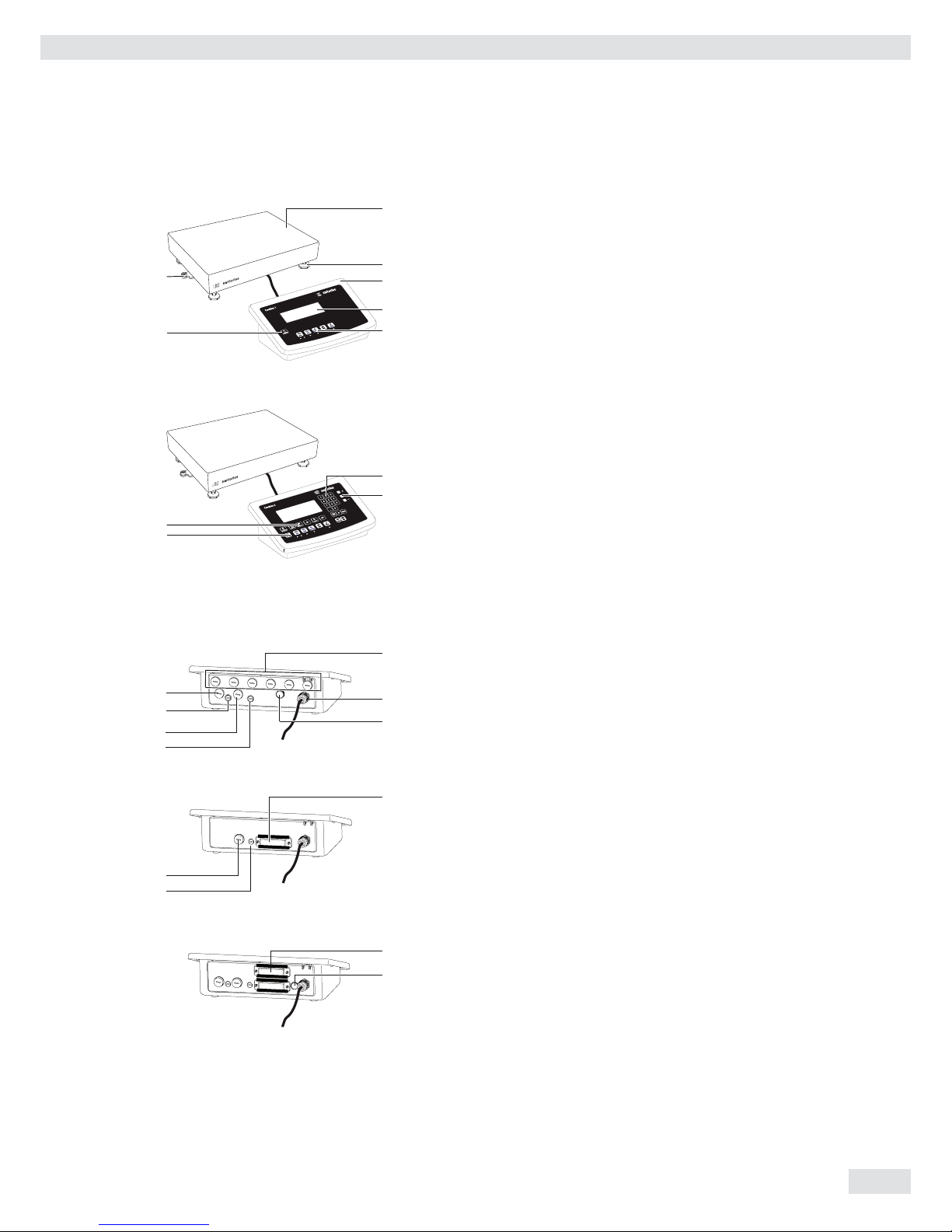
General View of the Equipment
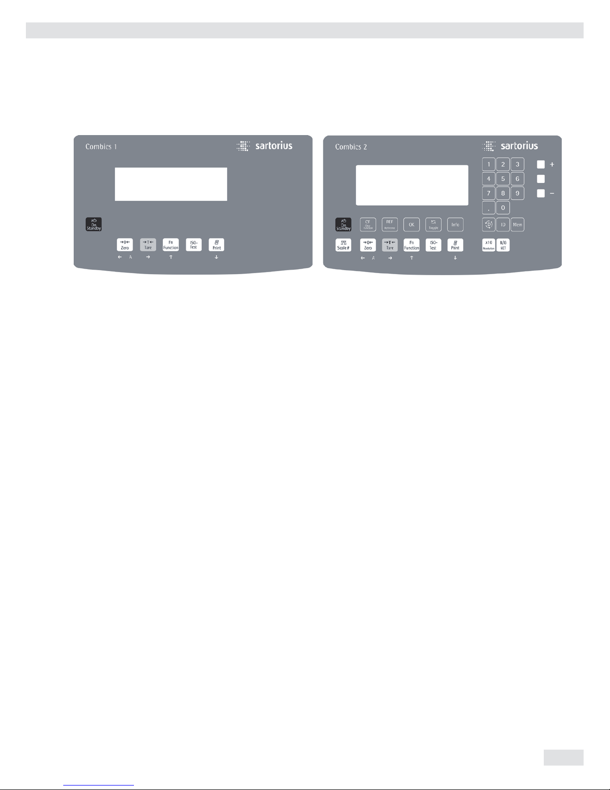
Combics 1 and 2
1 Level indicator
2 Load plate
3 Leveling feet
4 Indicator
5 Display (for a detailed diagram, please see the chapter
“Operating Design”)
6 General Function Keys: Zero, Tare, Switch function, Adjustment/
Calibration, Print/Data output
(see “Operating Design”)
7 On/Off Key
Combics 2 only
8 10 digit keypad for entering values
9 LEDs
(for checkweighing and classification)
10 Additional function keys (see “Operating Design”)
11 Toggle between weighing platforms (WP)
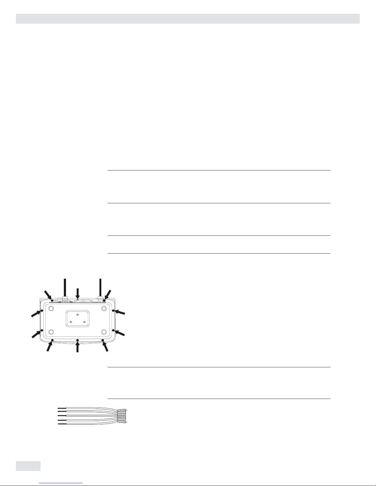
Rear view of indicator:
8 Connection options for
– COM 1 standard
– 2nd UNICOM interface for additional, optional functions
(e. g. Ethernet, profi bus, etc.)
– CAW2S: a barcode scanner can be connected via a terminal
block
9 Power cord with country-specific plug
10 Vent valve: 1.5 Nm
11 Weighing platform WP 1 and/or WP 2 connection
12 Input for menu access switch (standard or legal-for-trade mode)
for WP 1 and/or WP 2
13 RS-232C interface “COM 1” (standard equipment)
14 Second “UNICOM” interface (Combics 2 only)
15 Combics 2 only: PS/2 connection (barcode scanner, external
keypad)
Device Description
13
9
10
8
14
15
12
11
12
11
12
11
CAW1S | CAW2S | CAH1
CAW1P
CAW2P
2
3
1
4
5
7
6
8
10
9
11
8 Operating Instructions Combics Indicators
Installation
When a Combics complete scale is ordered with special equipment, the desired
options come pre-loaded from the factory.
Storage and Shipping Conditions
3
Once the equipment has been removed from the packaging, it may lose accuracy if
subjected to strong vibration.
3
If the load plate is lifted using a vacuum lifting pad, gloves, safety shoes and safety
gear must be worn. Risk of injury! This work may only be carried out by reliable
and authorized personnel.
3
Suspension points are provided for weighing platforms with an overall size of
1 + 1 m or larger.
Do not step under the load during weighing platform/load plate transport or when
lifting. Corresponding accident prevention regulations must be followed. Do not
damage the clamp boxes and load receptors during transport.
– Do not expose the equipment to unnecessarily extreme temperatures, moisture,
shocks, blows or vibration.
– Permissible storage temperature: –10°C to +40°C
Installation location
Avoid adverse infl uences at the place of installation:
– Extreme temperatures (operating temperature: –10°C to +40°C)
– Aggressive chemical vapors
– Extreme moisture (according to IP protection class)
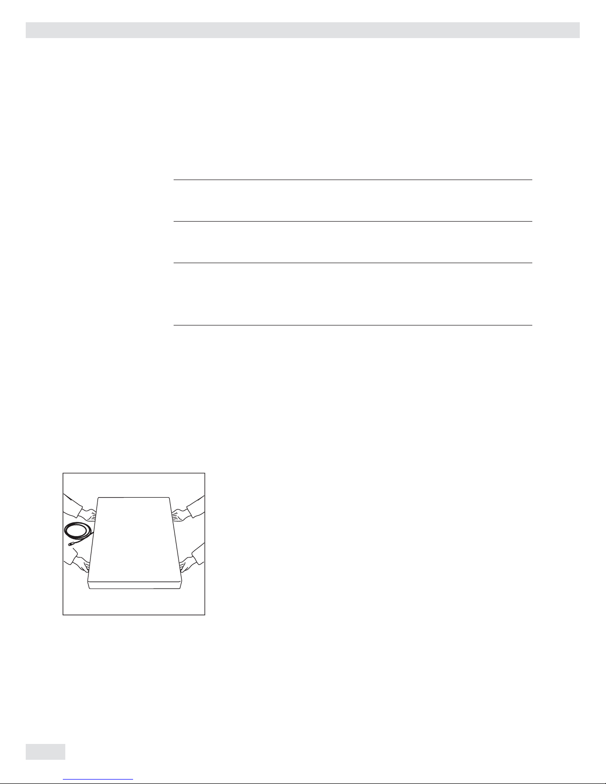
Unpacking
For devices with a platform size of 60 + 80 cm or larger:
t Protective gear must be worn (safety shoes and if required, gloves)
t Always lift on the side walls when lifting or transporting the weighing platform.
t After unpacking the device, check it for any visible damage as a result of rough
handling during shipment.
y If you detect any damage, proceed as directed in the chapter entitled “Care and
Maintenance” under “Safety Inspection."
t Save the original packaging for any future transport.
Unplug all connected cables before packing the equipment.
Check package contents
– Indicator
– Weighing platform
– Operating instructions
– Options (special accessories) as listed on the bill of delivery
Installation
Operating Instructions Combics Indicators 9
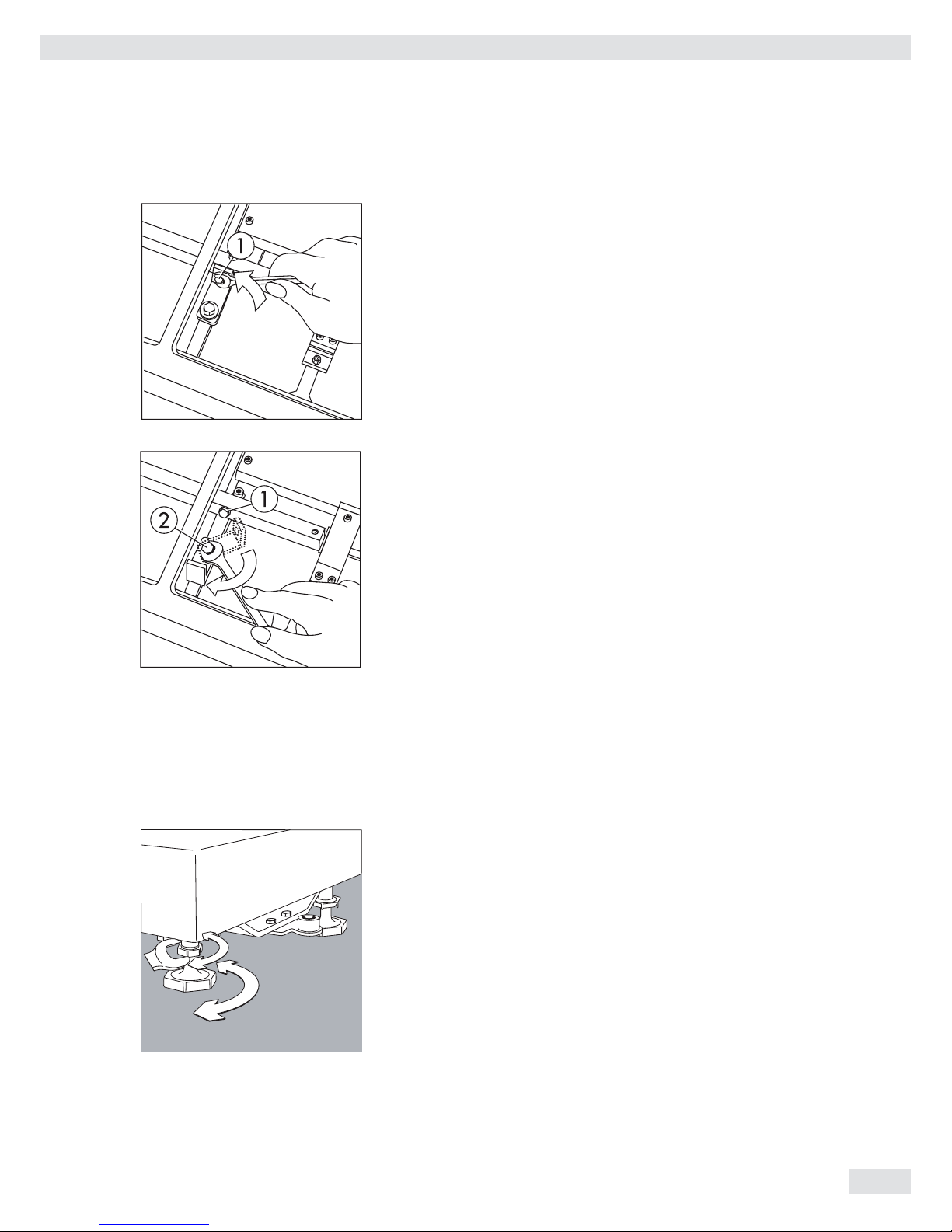
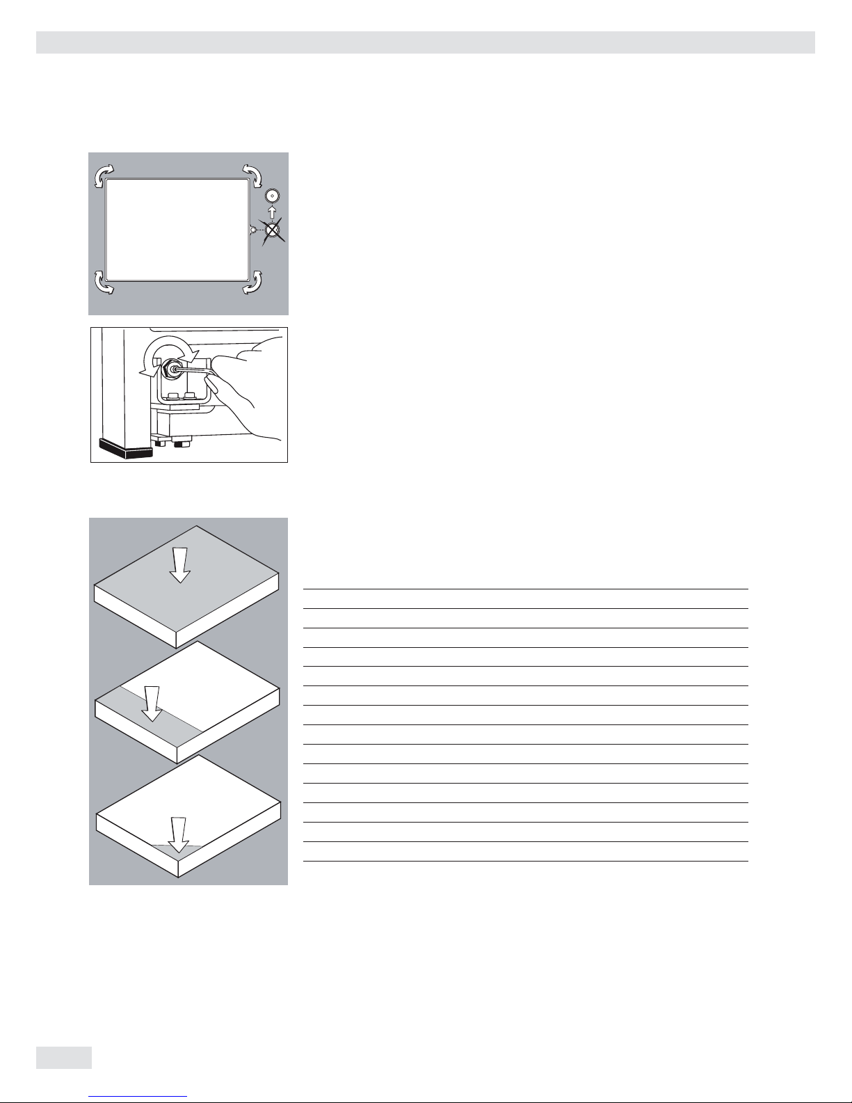
CAH1 models: Remove transport locks
t Place the weighing platform at its installation location, remove the
weighing pan.
t Remove the transport lock: Remove screw 1
t Loosen screw 2.
t Turn the mounting bracket 180° and re-secure screw 2.
t Re-attach screw 1 to the lever
3
The transport lock must be re-installed before transporting the weighing platform.
Weighing Platform, Leveling
The weighing platform must be exactly level to ensure reproducible weighing results
every time. Therefore, the weighing platform must always be re-leveled after it has
been moved to a different location.
t Remove the weighing pan.
t Loosen the lock nuts using a wrench (SW17).
t Use a SW5 Allen key to screw the leveling feet in/out.
Turning the leveling feet clockwise lifts the weighing platform,
turning the leveling feet counterclockwise lowers the weighing platform.
Installation
10 Operating Instructions Combics Indicators
t Align the weighing platform leveling feet so that air bubble is centered within
the circle of the level indicator.
t Check to ensure that all four leveling feet rest securely on the work surface.
y Each of the leveling feet must support an equal load.
t Re-fasten the lock nuts after leveling:
Small platforms (1 measuring cell) counter to the platform frame,
large platforms (4 measuring cells) counter to the platform foot.
t Place the weighing pan on the scale.
Operating Limits
You should not exceed the highest load for weighing platforms.
The highest capacity for the weighing platform is as follows depending on the load
used (center, side, one-sided corner load):
Platform size Center Side Corner
320 + 240 50 35 20
400 + 300 130 85 45
500 + 400 300 200 100
500 + 400 P* 600 400 200
650 + 500 S** 450 300 150
800 + 600 P* 1200 800 400
800 + 600 S** 900 600 300
800 + 800 4500 3000 1500
1000 + 800 4500 3000 1500
1000 + 1000 4500 3000 1500
1250 + 1000 4500 3000 1500
1500 + 1250 4500 3000 1500
1500 + 1500 4500 3000 1500
2000 + 1500 4500 3000 1500
* Steel
** Stainless steel
For CAH* models Platform size Supported load (center) in kg
400 + 300 130
560 + 450 130
800 + 600 600
Installation

Operating Instructions Combics Indicators 11
Shock Resistance
The weighing platform has a robust design; however, falling weighing samples, side
impacts and shocks should be avoided. The weighing platform can withstand loads
specifi ed in the DIN standard IEC68 Part 2-27.
Notes on Planning Superstructures
3
Superstructures must be completely attached before the weighing platform is
connected to the power.
The weighing platform is designed for system integration. Scale drawings are the
basis for the selection of the required superstructures. The fi xing of model CAH*IG*
weighing platforms should be carried out using the YAS04IS fastening kit.
Moving or rotating parts on the weighing pan must be designed so that the
weighing results are not infl uenced. Rotating parts should be counterbalanced,
for example.
The weighing pan must be free on all sides so that there is no connection between
the weighing platform and fi xed parts due to falling parts or dirt. Cables and hoses
between the weighing platform and other devices may not exert any forces on the
weighing platform. These cables may not touch the weighing pan.
When setting up systems in hazardous areas (Zone 2 or 22), any relevant
specifi cations should be observed, e. g.: EN60079-14.
The design should ensure that moving parts do not cause electrostatic discharges
(e. g. roller conveyors).
Preload Range (Zero Set Range)
The weight of the superstructures that are attached to the weighing platform is
designated as a “preload.” The preload is electronically compensated for in the
weighing platform so that the full weighing range remains available and thus
zeroing and/or calibration/adjustment (with external weights) is possible.
Greater preloads reduce the weighing capacity. You may not fall below the following
weighing range values:
– For CAH*E-16ED... and CAH*E-32ED... a min. 20 kg weighing range must be
maintained
– For CAH*E-64ED... and CAH*G-64FE... a min. 35 kg weighing range must be
maintained
– For CAH*G-150IG-H and CAH*G-300IG-H a min. 60 kg weighing range must be
maintained
The preload must always be set before verifi cation.
Acclimatizing the Device
Condensation can form on the surfaces of a cold device when it is brought into a
substantially warmer area.
t Allow the device to acclimatize for about 2 hours at room temperature, leaving
it unplugged from AC power.
Installation
12 Operating Instructions Combics Indicators
Getting Started
Steps 1.) Set up the weighing platform with the indicator.
2.) Level the weighing platform
3.) Connect peripheral devices, e .g. printer to the COM 1 or UNICOM interface:
see Data Interfaces chapter starting on page 99
4.) Connect the device to AC power
5.) Carry out an alignment: for adjustment, see page 27, for linearization see
page 24
Connecting Peripheral Devices or Another Weighing Platform
An analog Sartorius platform (CAPP, CAPS) or an IS weighing platform is connected
at the factory to the Combics indicator WP1 input.
3
The load cell should be connected by a certified technician who has received spe-
cialized training from Sartorius. Any installation work that does not conform to the
instructions in this manual results in forfeiture of all claims under the manufacturer’s warranty.
3
Peripheral devices should be connected by a certified technician who has received
specialized training from Sartorius. Any installation work that does not conform to
the instructions in this manual results in forfeiture of all claims under the manufacturer’s warranty.
3
Disconnect the equipment from the power supply before starting connection work.
t Place cables from peripheral devices next to the indicator.
CAW1S, CAW2S (IP69K) t Opening the Combics indicator:
� Loosen the ten cap nuts on the front panel. Remove the front panel.
Installing Connection and Interface Cables
3
The cable gland (IP69K protection) is pre-mounted on the indicator.
Please use extreme caution when performing any work on the equipment that
affects this cable gland.
You must use a torque wrench. The torque for this cable gland is 5 Nm.
Preparing Cables
t Strip approx. 14 cm from the end of the cable.
t Shorten the shielding to approx. 2 cm and pull back over the insulation.
t Strip approximately 5 mm of the insulation from the wires of the connecting
cable and affi x ferrules to the wire ends.
Getting Started
Operating Instructions Combics Indicators 13
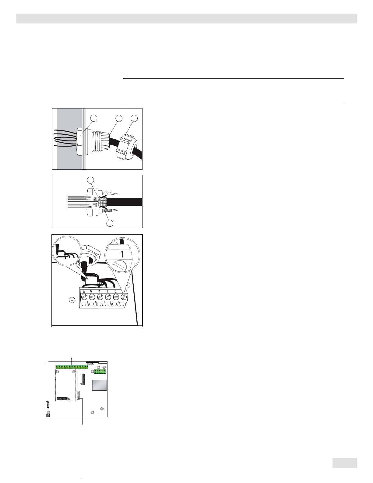
Attaching the Cable Entry
3
Please use extreme caution when performing any work on the equipment that
affects this cable gland. You must use a torque wrench.
The torque for this cable gland is 5 Nm.
4
1
5
t Remove the protective cap from the bore hole on the indicator.
t Insert the included cable gland through the bore hole and secure from the inside
using the locknut (1).
2
3
t Insert the cable through the cable gland until the shielding (2) comes into
contact with the clamps (3). Tighten the screw-down nut (4) until the gasket (5)
inserted between the screw-down nut and cable forms a small beaded rim.
t Check the shielding and clamps.
t Securely connect the wires of the connecting cable in accordance with the
terminal assignments.
t After you close the housing again, use a pressure gauge to check the integrity of
the IP69K protection. For details, contact the Sartorius Service Center.
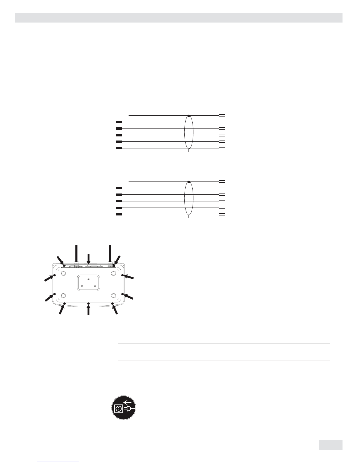
Connecting Cables
t Insert all cable wires through the ferrite case, wind them around the ferrite case
and then reinsert back through the ferrite case.
t Screw the wires tightly into the clamps.
See the following pages for terminal pin allocation
t Refer to the data sheet or operating instructions of the weighing platform for
details on the assignment of wire colors/signals. Ensure any lines that are not
assigned are insulated correctly.
t When connecting a load receptor that uses 4-conductor technology (the cable of
the weighing platform to be connected only has 4 lines), connect clamp pairs 1
and 2 (EXC+ und SENSE+), and 5 and 6 (SENSE- und EXC-) with a wire jumper.
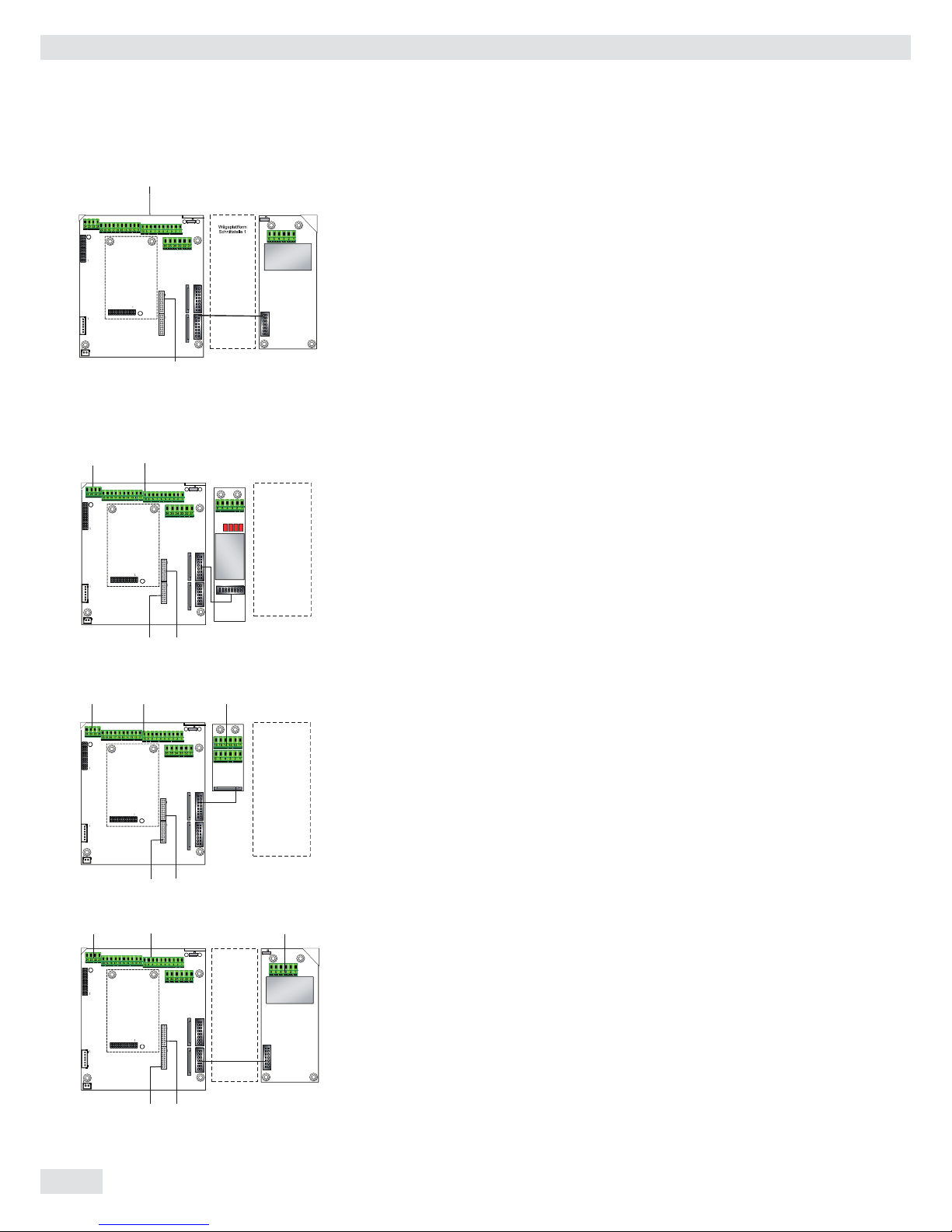
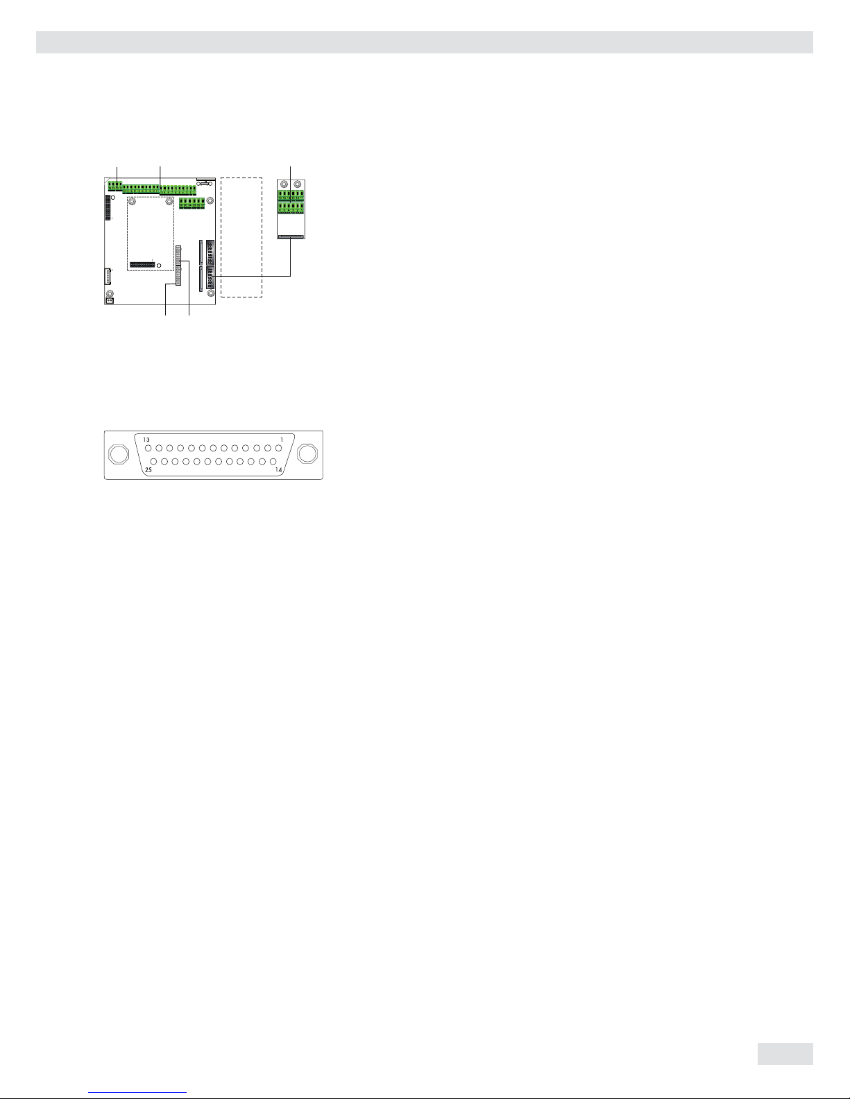
Connecting Peripheral Devices: Combics 1,
Model CAW1S
Digital PCB
COM1 terminal assignments
1 LOAD_PRINTER 11 Clear to Send (CTS)
2 RESET_OUT 12 Data Terminal Ready (DTR)
3: GND 13 Data Input (RXD)
4 GND 14 Data Output (TXD)
5 5V_OUT 15 GND
6 5V geschaltet 16 Universal In
7 GND 17 Control Output: “lighter"
8 GND 18 Control Output: “equal"
9 n.c. 19 Control Output: “heavier"
10 LINE_OUT 20 Control Output: “set"
D connection of indicator
Com 1
D
Getting Started
14 Operating Instructions Combics Indicators
Plattform: -MCE, -UCE, -RCE: Connection for ADU 10.000e
1 EXC+
2 SENSE+
3 OUT+
4 OUT5 SENSE6 EXC
D connection of indicator
Interface Pin Assignments: Combics 2, Model CAW2S
Digital PCB
COM1 terminal assignments (applies to all PCBs)
1 LOAD_PRINTER 11 Clear to Send (CTS) 21 5 V switched
2 RESET_OUT 12 Data Terminal Ready (DTR) 22 PS/2_Data
3: GND 13 Data Input (RXD) 23 PS/2_Clock
4 GND 14 Data Output (TXD) 24 GND
5 5V_OUT 15 GND 31 Not assigned
6 5V switched 16 Universal In 32 Not assigned
7 GND 17 Control Output: “lighter" 33 Not assigned
8 GND 18 Control Output: “equal" 34 Not assigned
9 n.c. 19 Control Output: “heavier" 35 Not assigned
10 LINE_OUT 20 Control Output: “set" 36 Not assigned
D Indicator connection
LED (LED connection)
Interface PCB for RS-232/485 for IS weighing platform
(option A6/A7)
A6/7
1 CTS 11 TxD/RxD+
2 DTR 12 TxD/RxD3 RxD 13 LINE_OUT
4 TxD 14 LINE_OUT
5 GND 15 GND
6 Calibration Lock 16 GND
D Indicator connection
LED (LED connection)
Interface PCB for ADC 10.000e (option A20)
A20
1 EXC+
2 SENSE+
3 OUT+
4 OUT5 SENSE6 EXCD Indicator connection
LED (LED connection)
Com 1PS/2
Weighing platform
Interface 2
D
LED
Com 1PS/2
Weighing platform
Interface 1
A20
D
LED
Weighing platform
Interface 2
Com 1PS/2 A6/7
D
LED
Getting Started
Com 1
D
Operating Instructions Combics Indicators 15
Interface PCB for RS-232/485 for IS weighing platform
(option A62/A72)
Interface PCB A6/7 and A62/72
1 CTS 11 TxD/RxD+
2 DTR 12 TxD/RxD3 RxD 13 LINE_OUT
4 TxD 14 LINE_OUT
5 GND 15 GND
6 Calibration Lock 16 GND
D Indicator connection
LED (LED connection)
Pin Assignment Chart
Models CAW1P and CAW2P (IP44 protection)
COM1 female connectors:
25-pin D-Submini female connector (DB25S) with screw lock hardware for cable
gland
Recommended interface connector:
25-pin D-Submini (DB25) with shielded cable clamp assembly and shield plate
(Amp type 826 985-1C) and fastening screws (Amp type 164868-1)
COM1 pin assignments
Pin 1: Shield
Pin 2: Data output (TxD)
Pin 3: Data input (RxD)
Pin 4: GNO
Pin 5: Clear to Send (CTS)
Pin 6: Not assigned
Pin 7: Internal ground (GND)
Pin 8: Internal ground (GND)
Pin 9: Not assigned
Pin 10: Not assigned
Pin 11: +12 V for printer
Pin 12: RES_OUT\
Pin 13: +5 V Switch
Pin 14: Internal ground (GND)
Pin 15: Universal switch
Pin 16: Control output: “lighter"
Pin 17: Control output: “equal"
Pin 18: Control output: “heavier"
Pin 19: Control output: “set”
Pin 20: Data Terminal Ready (DTR)
Pin 21: Ground power supply (GND)
Pin 22: Not assigned
Pin 23: Not assigned
Pin 24: Power supply +15...25 V (peripherals)
Pin 25: +5 V
Weighing platform
Interface 2
Com 1 A62/72
D
LED
PS/2
Getting Started

16 Operating Instructions Combics Indicators
3
1
4
2
6
5
PS/2 socket pin assignment on Combics 2
Pin 1: Keyboard data (data interface cable)
Pin 2: Not assigned
Pin 3: GND (ground)
Pin 4: 5V switched
Pin 5: Keyboard clock
Pin 6: Not assigned
Connecting an IS Weighing Platform to a Combics 2
You can connect an IS weighing platform to WP2.
Features – IS weighing platforms process weighing data independently of the indicator.
– Internal calibration/adjustment option
– IS...-0CE models: have a separate approval number, printed on a tag that is
affi xed to the cable.
– Please observe the conditions described in the manual for the weighing platform
you connect.
Cabling Diagram - Connection to a PC
Use the following cables to connect a PC to the indicator in accordance with the
RS-232C/V24 standard (max. cable length 15 m):
Models CAW1P, CAW2P: connecting cable 7357312
Models CAW1S, CAW2S: connecting cable YCC02-D9F6
V24
NOTE: This equipment has been tested and found to comply with the limits pursuant to part
15 of FCC Rules. These limits are designed to provide reasonable protection against harmful
interference. This equipment generates, uses and can radiate radio frequency energy and, if
not installed and used in accordance with these instructions, may cause harmful interference
to radio communications. For information on the specific limits and class of this equipment,
please refer to the Declaration of Conformity. Depending on the particular class, you are either
required or requested to correct the interference. If you have a Class A digital device, you need
to comply with the FCC statement as follows: “Operation of this equipment in a residential
area is likely to cause harmful interference in which case the user will be required to correct the
interference at his own expense.“
3
PS/2 socket pin assignment on Combics 2
Pin 1: Keyboard data (data interface cable)
Pin 2: Not assigned
Pin 3: GND (ground)
Pin 4: 5V switched
Pin 5: Keyboard clock
Pin 6: Not assigned
Connecting an IS Weighing Platform to a Combics 2
You can connect an IS weighing platform to WP2.
Features – IS weighing platforms process weighing data independently of the indicator.
– Internal calibration/adjustment option
– IS...-0CE models: have a separate approval number, printed on a tag that is
affixed to the cable.
– Please observe the conditions described in the manual for the weighing platform
you connect.
Cabling Diagram - Connection to a PC
Use the following cables to connect a PC to the indicator in accordance with the
RS-232C/V24 standard (max. cable length 15 m):
Models CAW1P, CAW2P: connecting cable 7357312
Models CAW1S, CAW2S: connecting cable YCC02-D9F6
3
1
4
2
6
5
V24
Getting Started
Operating Instructions Combics Indicators 17
Cable Diagrams
Pin assignments for the cable from the indicator to an RS-232 PC interface (COM1).
Indicator side PC side
Models CAW1P, CAW2P DSUB connector
25-pin D-Sub male connector 9-pin or 25-pin
1
Sgn GND 7 5 GND 7 GND
TxD 2 2 RxD 3 RxD
RxD 3 3 TxD 2 TxD
DTR 20 8 CTS 5 CTS
CTS 5 4 DTR 20 DTR
Models CAW1S, CAW2S
Open cable end DSUB connector
9-pin or 25-pin
Sgn GND 15 5 GND 7 GND
TxD 14 2 RxD 3 RxD
RxD 13 3 TxD 2 TxD
DTR 12 8 CTS 5 CTS
CTS 11 4 DTR 20 DTR
Closing the Combics Indicator
t Re-attach the front panel and secure it with the ten cap nuts ( 1Nm ).
Connecting the Device to AC Power
The indicator is powered through the pre-installed power cord. The power supply is
integrated into the indicator. The device can be operated with a supply voltage of
100 V to 240 V.
3
The power connection must be made in accordance with the regulations applicable
in your country.
Make sure that the voltage rating printed on the manufacturer's ID label is identical
to that of your local line voltage. If the voltage specifi ed on the label or the plug
design of the AC adapter do not match the rating or standard you use, please
contact your Sartorius offi ce or dealer.
t Check the voltage rating and plug design.
t The device must be plugged into a properly installed wall outlet.
Getting Started
18 Operating Instructions Combics Indicators
Protection Class 1 Device
t The device must be plugged into a properly installed wall outlet which has
a protective grounding conductor (PE).
Safety Precautions
3
If you use an electrical outlet that does not have a protective grounding conductor,
ensure that an equivalent protective conductor is installed by a certified electrician
(as specified in the applicable regulations for installation in your country). The protective effect must not be negated by using an extension cord without a protective
grounding conductor.
Before using for the fi rst time, any superstructure parts must be completely installed.
Avoid connecting the equipment to lines that have a heavy electrical load, e. g.
compressors, large machinery, etc.
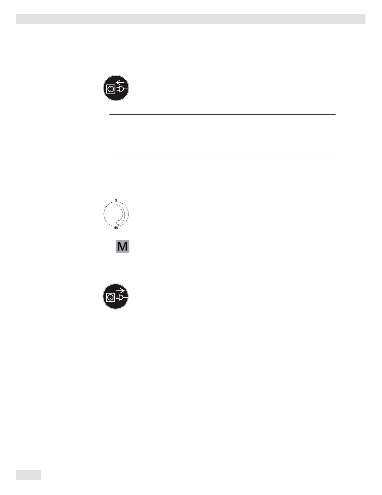
Warm-up Time
To deliver exact results, the device must warm up for at least 30 minutes after
connection to AC power. Only after this time will the device have reached the
required operating temperature.
Using a Verified Device in Legal Metrology:
Ensure that there is a warm-up time of at least 24 hours after connection to the
power supply.
Connecting a Barcode Scanner (Accessory; Order No. YBR03PS2)
t Disconnect the indicator from AC power (unplug the AC adapter)
For CAW2P models:
t Connect the barcode scanner via PS/2.
For CAW2S models:
t Please see “Pin Assignment Charts,” page 15 (implemented via the YCC02-BR02
connecting cable or as option M8)
Getting Started

Operating Instructions Combics Indicators 19
Scale Confi guration
Service Mode
Purpose The Service mode enables access to additional menu items in the Setup menu
(setup) which are not displayed when the Service mode is not active. The most
important calibration and adjustment work for the indicator and for the connected
weighing platform can be carried out in the Service menu, e. g. ADC confi guration.
When the Service mode is active, an “S” is shown in the top right-hand corner of the
display. To deactivate the Service mode, restart the indicator (turn the indicator off
and back on again).
In Service mode, the Setup menu is expanded with the following parameters after
entering the user password:
– S-DATE for entering the next service date
– SER.NO for entering the device serial number
– MODEL with the model description
– S-SQMIN
– ALIB.MEM for deleting the Alibi memory
The Setup menu for WP1 and WP2 can be extended to include the following
setting options:
Param1
CAL./ADJ. Calibration, adjustment 1.9.
Internal linearization (for WP-2 only) 1.9.5
CAL.EXT External linearization with default weights 1.9.6
CAL.E.USR. External linearization with user-defi ned weights (entered under 1.18) 1.9.7
SET.PREL. Setting the preload 1.9.8
DEL.PREL. Clearing the preload 1.9.9
HND.XT / CAL./ADJ. Entering the adjustment and linearization weights 1.18.
LIN. WT.1 Entering the lin. weight 1 1.18.2
LIN. WT.2 Entering the lin. weight 2 1.18.3
LIN. WT.3 Entering the lin. weight 3 1.18.4
LIN. WT.4 Entering the lin. weight 4 1.18.5
ADJ.W/O.W Adjustment without weights (entering the characteristic data
of the load cell(s)) 1.19.
NOM.LOAD Nominal load 1.19.1
RESOLUT Resolution 1.19.2
SENSIT.1 Sensitivity in mV/V for cell 1 (or average value for all load cells) 1.19.3
SENSIT.2 Sensitivity in mV/V for cell 2 1.19.4
SENSIT.3 Sensitivity in mV/V for cell 3 1.19.5
SENSIT.4 Sensitivity in mV/V for cell 4 1.19.6
SAVE Save values for 1. 19 1.19.7
GEOG.DAT Adjustment location (geographical data; or alternatively the
gravitational acceleration at the place of installation) 1.20.
LATITUD Latitude in degrees 1 20.1
ALTITUD Elevation in meters above sea level 1 20.2
GRAVITY. Gravitational acceleration 1 20.3
SAVE. Save values for 1. 20 1 20.4
ADC Confi guration 11
Applying the serial number of the IS weighing platform (verifi ed weighing
platform at WP2) 12.1
Apply the serial number 12.1.1
Inactive (standard WP) 12.1.2
Confi guring Weighing Platforms
20 Operating Instructions Combics Indicators
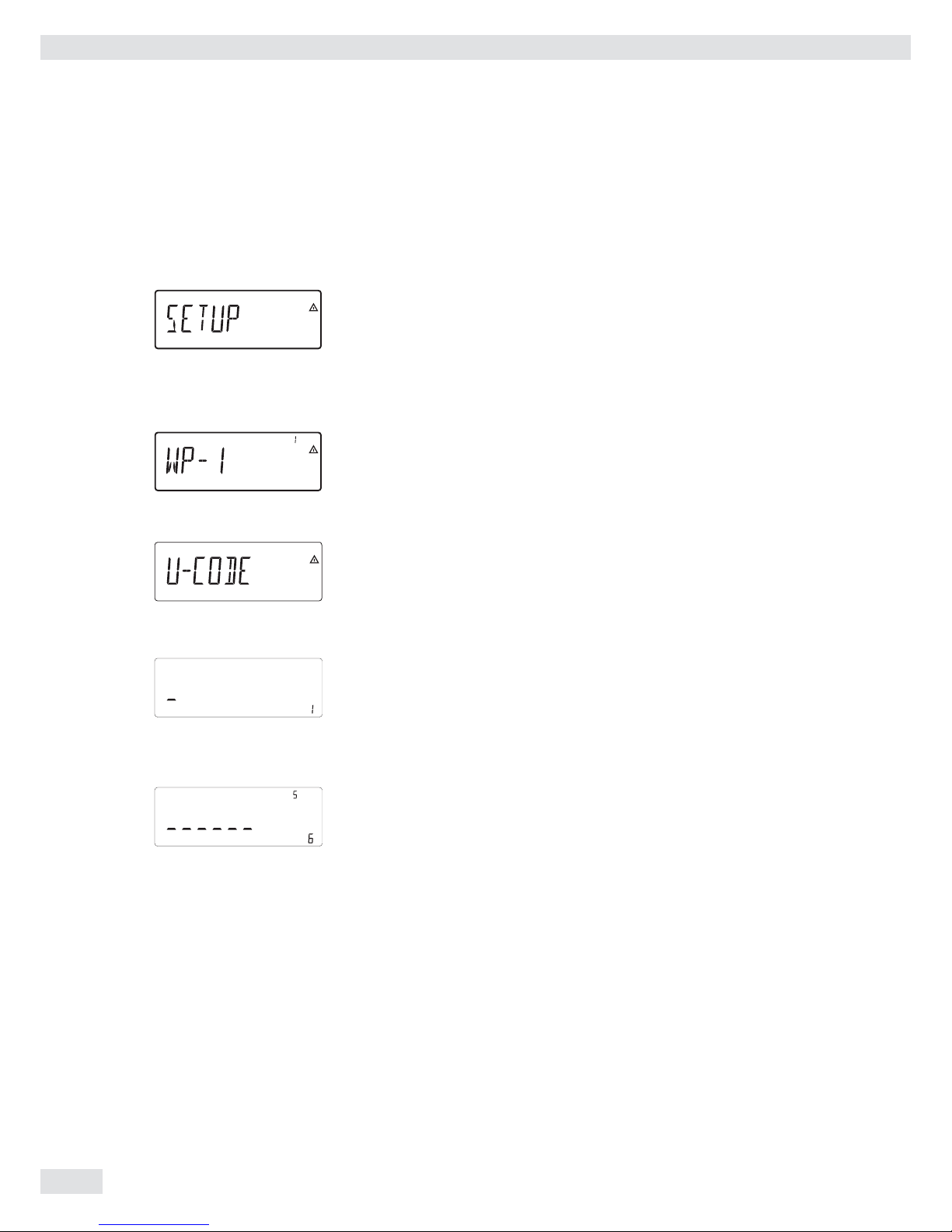
Activating the Service Mode
e ... ) t Switch to the Menu mode (see page 32).
k k ... t Access the Setup menu.
) t Select Setup
If a password is requested at this point, enter the service password
(see Appendix) and continue with “Saving the service password."
k k ... t Access the U-Code menu item
) t Select U-Code
t Enter the service password (see Appendix).
) t Apply the service password
y The Service mode is active: an “S” appears in the top right-hand corner of the
display.
( ( t Return to Setup in the Service mode.
Confi guring Weighing Platforms

Operating Instructions Combics Indicators 21
Entering Geographical Data for Use in Legal Metrology
Purpose Entering geographical data allows the external adjustment of weighing equipment
at a place (e. g. at the manufacturer or vendor's place of business) that is not the
same as the place of installation. If the weighing equipment is adjusted at the place
of installation, it is not necessary to enter geographical data.
The sensitivity of weighing equipment changes depending on the place of
installation as it is dependent on the on-site gravitational force – or, more precisely,
on gravitational acceleration. Saving geographical data makes it possible to change
the place of installation of the weighing equipment after external adjustment has
been carried out.
The adjustment of weighing equipment is valid at the place of installation and
within a specifi c tolerance zone. At 3000 e this zone extends ±100 km from the set
geographical latitude and ±200 m from the set elevation above sea level.
Installation Location in Germany An exception to this is the setting for “Germany (Zone D):” If during external
adjustment of weighing equipment within Germany the geographical data
– Geographical latitude: 51.00 degrees
– 513 m elevation above sea level
are entered, the weighing equipment can be used throughout Germany.
Gravitational acceleration for “Germany (Zone D)” is 9.810 m/s
2
. On delivery the
geographical data for “Germany (Zone D)” are entered in the output device.
It is recommended to use the geographical data settings for “Germany (Zone D)”
when adjusting and delivering the weighing equipment within Germany. Entering
exact geographical data will lead to a higher level of accuracy but will also restrict
the tolerance zone.
Setup Information – It is only possible to enter geographical data when the menu access switch is
open.
– When the Service mode is activated, you can enter geographical data in the
Setup menu for the fi rst weighing platform under WP-1 and COM1 / WP-2,
UNICOM / WP-2 or COM-WP for the second weighing platform. The settings are
made in the corresponding Setup menu under menu item 1.20.
– You can enter either the “geographical latitude in degrees” (LATITUD menu
item 1.20.1) and “elevation in m above sea level” (ALTITUD menu item 1.20.2),
or the value for gravitational acceleration (GRAVITYmenu item 1.20.3).
Gravitational acceleration takes precedence over the geographical latitude and
elevation of the location: If it has been entered, input fi elds for latitude and
elevation show the values 99999.99 and 9999999 respectively. If only elevation
and latitude have been entered, 0000000 is displayed for gravitational
acceleration.
3
If you return to the highest level of the Setup menu without saving the
configuration parameter beforehand (save menu item 1.20.4) any settings that
have been made will be deleted.
Confi guring Weighing Platforms

22 Operating Instructions Combics Indicators
Procedure t Open the menu access switch.
If the device is part of a verifi ed weighing facility, this will only be possible if the
verifi cation seal is broken. The weighing equipment must then be verifi ed again.
t Activate the Service mode.
t Select the weighing platform.
t Enter the geographical data for the place of adjustment under menu items
1.20.1 to 1.20.3 and save them under menu item 1.20.4. The data can be
obtained from the relevant land registry or Ordnance Survey.
t Carry out external calibration.
t After the calibration, enter the geographical data for the place of installation
under menu items 1.20.1 to 1.20.3 and save them under menu item 1.20.4.
t Close the menu access switch.
y The weighing equipment can now be operated at the place of installation, and
within the abovementioned tolerance zone.
Note: The set geographical values are displayed during the adjustment procedure if the
display of the data has been activated in the Setup menu under UTILIT. menu item
8.12.2 (factory setting: 8.12.1, display deactivated).
When the display is activated the adjustment procedure is as follows:
y If the elevation and geographical latitude are used, the word ALTITUD will
appear briefl y followed by the set elevation (in meters above sea level) after the
start of the CAL adjustment procedure.
t Confi rm the display using the ) key (cancel using the ( key).
y Then the word LATITUD will be displayed briefl y followed by the set
geographical latitude in degrees.
t Confi rm the display using the ) key (cancel using the ( key).
y You are then asked to place the calibration weight on the weighing platform.
If gravitational acceleration has been entered instead of elevation and
geographical latitude, the word GRAVITY will appear briefl y, followed by the set
value for gravitational acceleration.
t Confi rm the display using the ) key (cancel using the ( key).
Menu structure for entering the geographical data
GEOG.DAT Adjustment location (geographical data; or alternatively
the gravitational acceleration at the place of installation) 1.20.
LATITUD Latitude in degrees 1.20.1
ALTITUD Elevation in meters above sea level 1.20.2
GRAVITY. Gravitational acceleration 1.20.3
SAVE. Save values for 1. 20 1.20.4
Confi guring Weighing Platforms

Operating Instructions Combics Indicators 23
Entering Adjustment and Linearization Weights
Purpose Entering adjustment and linearization weights.
Setup Information – The Service mode must be activated in order for linearization weights to be
entered under menu items 1.18.2 to 1.18.5 (see page 20).
– Adjustment and linearization weights can be entered in the Setup menu under
WP-1 for the fi rst weighing platform and COm1 / WP-2, UNICOM / WP-2 or
COm-WP for the second weighing platform. The settings are made in the
corresponding Setup menu under menu item 1.18.
– The Service mode does not have to be activated in order for external user-
defi ned adjustment weights to be entered under menu item 1.18.1.
– The adjustment and linearization weights must be entered in the unit selected
for the ADC confi guration under menu item 11.8.
Procedure t Activate the Service mode (only necessary if linearization weights are going to
be entered)
t Select the weighing platform.
t Enter the external user-defi ned adjustment weight under menu item 1.18.1
t Enter the external linearization weight under menu items 1.18.2 to 1.18.5.
Menu structure for entering the adjustment and linearization weights
HND.XTEntering the adjustment and linearization weights 1.18.
Entering external user-defi ned adjustment weight (Service mode not required) 1.18.1
LIN. WT.1 Entering the lin. weight 1 1.18.2
LIN. WT.2 Entering the lin. weight 2 1.18.3
LIN. WT.3 Entering the lin. weight 3 1.18.4
LIN. WT.4 Entering the lin. weight 4 1.18.5
Function Allocation of the J Key
Purpose The J key is usually used for the calibration/adjustment function. For detailed
information about calibration and adjustment, see “Operation” starting on page 45.
The following additional functions can be allocated to the key when the Service
mode is activated:
– External linearization with default weights (menu item 1.9.6)
– External linearization with the linearization weights (menu item 1.9.7) entered
under menu item 1.18
– Internal linearization (for WP-2 only) (menu item 1.9.5)
– Set preload function (menu item 1.9.8)
– Clear preload function (menu item 1.9.9)
3
Once linearization has been completed, or after a preload has been set or deleted
the function of the J key must be reallocated back to its original function in the
Setup menu, e.g. external calibration/adjustment with default weights (see menu
item 1.9).
Menu structure for the function allocation of the J key
CAL./ADJ. Calibration, adjustment 1.9.
Ext. calibration/adjustment with default weights (Service mode not required) 1.9.1
Ext. calibration/adjustment with user-defi ned weights
(Entry under 1.18, Service mode not required) 1.9.3
CAL.INT Internal linearization (for WP-2 only) 1.9.5
CAL.EXT External linearization with default weights 1.9.6
CAL.E.USR. External linearization with user-defi ned weights (entered under 1.18) 1.9.7
SET.PREL. Setting the preload 1.9.8
DEL.PREL. Clearing the preload 1.9.9
BLOCKED Key blocked 1.9.10
Confi guring Weighing Platforms
24 Operating Instructions Combics Indicators
External Linearization
Setup Information – External linearization when weighing in legal metrology is only possible when
the menu access switch is open.
– The “external linearization” function must be allocated to the J key (menu
item 1.9.6 or 1.9.7).
3
Once linearization has been completed, the J key must be reallocated back to its
original function in the Setup menu, e. g. external calibration/adjustment with
default weights (Setup menu item 1.9).
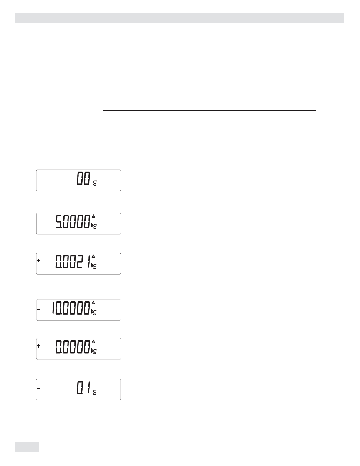
Procedure
t For scales used in legal metrology: Open the menu access switch.
( t Zero the weighing platform.
t Activate the Service mode (see Page20).
J t Start linearization.
t After approximately 2 seconds you will be prompted to place the fi rst
linearization weight on the platform.
t Place the required weight on the platform.
y After a short time the difference between the measured value and the true
weight of the sample will be displayed.
) t Save the linearization weight (cancel using the ( key).
y You will then be prompted to place the second linearization weight on the
platform.
t Repeat the procedure for all required linearization weights.
y After the last linearization weight has been saved you will be prompted to
remove any load from the weighing pan.
t Unload the weighing pan.
t After a short period of time the zero point will be applied automatically and the
indicator will automatically switch back to weighing mode.
t Re-close the menu access switch.
Confi guring Weighing Platforms
Operating Instructions Combics Indicators 25
Setting the Preload
Setup Information – Setting the preload when weighing in legal metrology is only possible when the
menu access switch is open.
– The “Set Preload” function (menu item 1.9.8) must be allocated to the J key
(see page 137).
3
Once the preload has been set, the J key must be reallocated back to its original
function in the Setup menu, e. g. external calibration/adjustment with default
weights (Setup menu item 1.9).
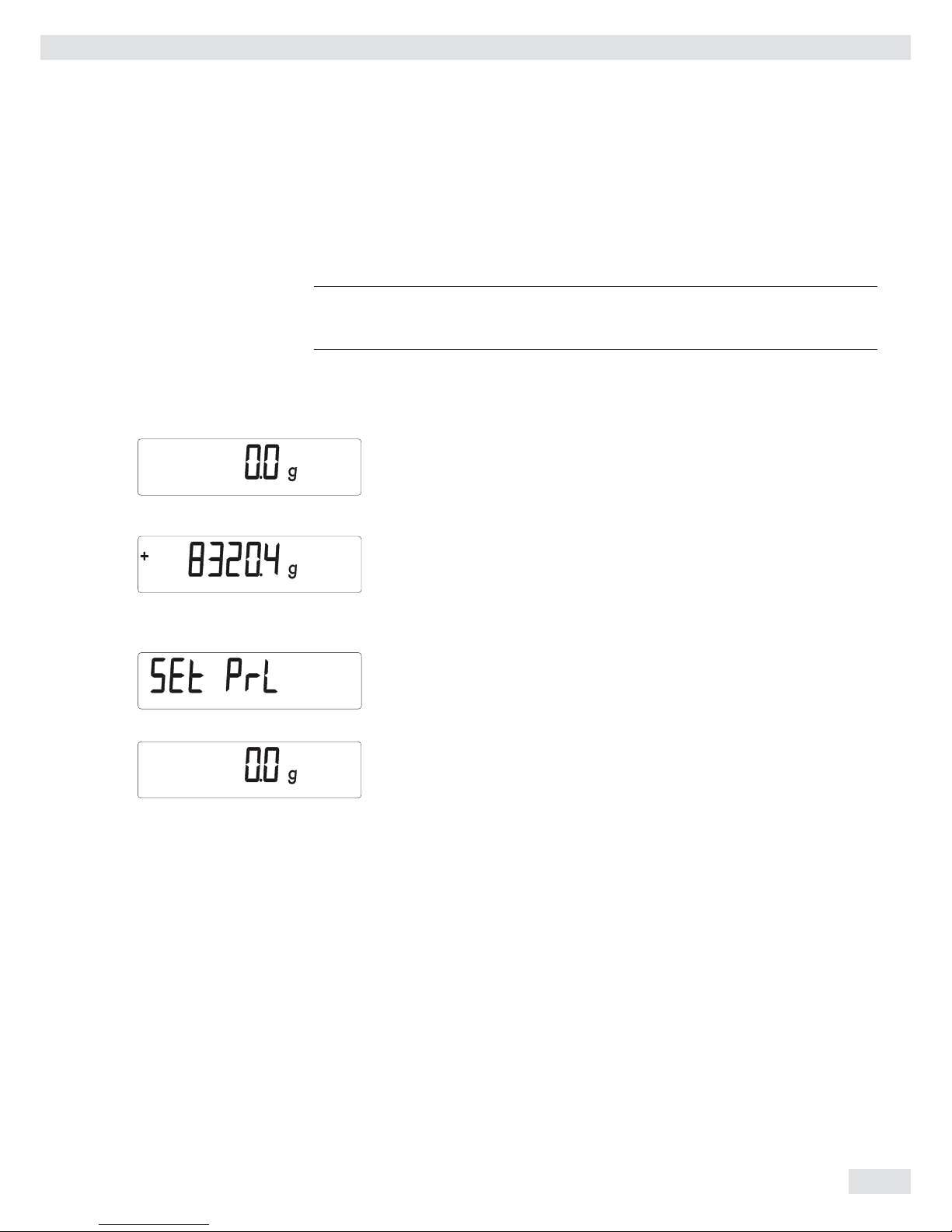
Procedure
t For scales used in legal metrology: Open the menu access switch.
( t Zero the weighing platform.
t Place the preload weight on the weighing platform.
J t Start the “Set Preload” function.
y After a short period of time the preload will be applied and the indicator will
automatically switch back to weighing mode.
t Re-close the menu access switch.
Confi guring Weighing Platforms
26 Operating Instructions Combics Indicators
Clearing the Preload
Setup Information – Deleting the preload when weighing in legal metrology is only possible when the
menu access switch is open.
– The “Delete Preload” function (menu item 1.9.9) must be allocated to the J
key (see page 137).
3
Once the preload has been deleted, the J key must be reallocated back to its
original function in the Setup menu, e. g. external calibration/adjustment with
default weights (Setup menu item 1.9).
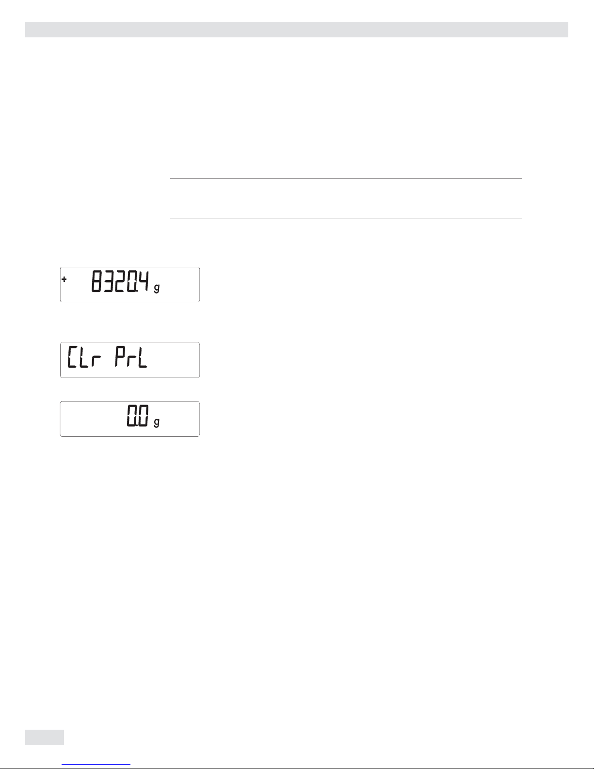
Procedure
t For scales used in legal metrology: Open the menu access switch.
t Remove the preload weight from the weighing platform.
) hold t Start the “Delete Preload” function.
y After a short period of time the preload will be deleted and the indicator will
automatically switch back to weighing mode.
t Re-close the menu access switch.
Confi guring Weighing Platforms

Operating Instructions Combics Indicators 27
Adjustment without Weights
In the Service menu, adjustment without weights can be carried out by entering the
characteristic data of the load cells.
3
Adjustment without weights may not be carried out on weighing equipment used
in legal metrology.
Setup Information – Adjustment without weights is only possible when the menu access switch is
open in the Service menu.
– When the Service mode is activated, you can enter the necessary parameters for
adjustment without weights in the Setup menu under WP-1 for the fi rst
weighing platform and COm1 / WP-2, UNICOM / WP-2 or COm-WP for the second
weighing platform. The settings are made in the corresponding Setup menu
under menu item 1.19.
– The “Nominal load” parameter must be entered in the kg unit.
– The “Resolution” parameter must be entered in the kg unit and must correspond
to the scale interval d entered for the ADC confi guration.
– The “Sensitivity” parameter is entered in mV/V ( see the data sheet for the
value).
h
The data entered are saved by selecting menu item 1.19.7. After saving, the data will
no longer be able to be read.
Procedure
t Open menu access switch.
t Activate the Service mode.
t Select the weighing platform.
t Enter the nominal load of the load cell(s) in kg under menu item 1.19.1. If the
weighing platform has multiple load cells, the nominal load must be multiplied
accordingly (e. g. 4 load cells, each of which has a capacity of 50 kg, will
produce a nominal load of 200 kg).
t Enter the resolution in kg under menu item 1.19.2. The value must correspond
to the scale interval d entered under menu item 11.4.1.
t Enter the sensitivity of the load cells in mV/V under menu item 1.19.3.
For weighing platforms with multiple load cells: Enter the individual values of
the load cells in 1.19.3 to 1.19.6 or enter the average of all load cells in 1.19.3.
t Save the values for adjustment without weighing under menu item 1.19.7.
t Close the menu access switch.
Menu structure for adjustment without weights
ADJ.W/O.W Adjustment without weights (entering the characteristic data
of the load cell(s)) 1.19.
NOM.LOAD Nominal load 1.19.1
RESOLUT Resolution 1.19.2
SENSIT.1 Sensitivity in mV/V for cell 1 (or average value for all load cells) 1.19.3
SENSIT.2 Sensitivity in mV/V for cell 2 1.19.4
SENSIT.3 Sensitivity in mV/V for cell 3 1.19.5
SENSIT.4 Sensitivity in mV/V for cell 4 1.19.6
SAVE Save values for 1. 19 1.19.7
Confi guring Weighing Platforms

28 Operating Instructions Combics Indicators
Operating Design
You can use the Combics 2 to record weight values from two weighing platforms,
calculate and display weight values through application programs, and assign IDs to
the samples weighed.
First, use the menu to confi gure the indicator for the desired application (printer
settings, etc.). Then you can begin weighing.
The indicator keypad is used for operation. Each key can be assigned a weighing
mode function and another function in the menu. Some of the keys also have an
additional function when pressed and held for longer than 2 seconds.
When a key is pressed that does not have an active operating mode function, an
acoustical signal (double beep) sounds and the message “——-—” is displayed for
2 seconds. The display then returns to the previous screen content.
Switching on the Device
e t Briefl y press the e key to turn on the indicator.
y The device carries out a self test every time it is turned on. During this time,
all display segments light up for several seconds.
y Then the display for the weighing mode appears.
The scale is started in the status it was in when it was turned off, e.g. with the
last selected application.
The scale starts in the weighing mode. You must open the Menu mode (see page 32)
to make settings or set up applications.
Operating Design
Operating Instructions Combics Indicators 29
Weighing Operation
Combics 1 Combics 2
Keys for all models
e On/Off key
When in Standby mode, STANDBY is displayed.
( Zero key
– Press the key less than 2 seconds: Zero
– Press the key longer than 2 seconds: Displays the adjustment/confi guration
counter
) Tare key
– Saves the numeric input as the tare weight
– Press the key longer than 2 seconds: Start calibration/adjustment
k
Function key: Depends on the confi guration in the Setup menu, switches between the
– First and second weighing unit
– Gross and net values (Combics 1 only)
– Normal and 10-fold higher display resolution (Combics 1 only)
– Results display and SQmin display
J ISO test: Start calibration or adjustment
p Print key
– Press the key less than 2 seconds: Print
– Press the key longer than 2 seconds: Print GMP footer
Keys for Combics 2 only
n Toggle key: When two platforms are connected, this key toggles the display
between the two readouts.
The following four keys are used for operating the individual applications. Their
exact function is described in the respective section for the application.
c Delete key: Deletes initialization values or totalizing memory. During numeric entry
the last character entered is deleted.
r Reference value key: Changes the set reference value.
O OK key: Applies values or starts an application program.
w Toggle key: Toggles between display modes within an application program.
Operating Design

30 Operating Instructions Combics Indicators
I Info key: Used to display application parameters and manual tare values (Info after
pressing a follow-up key, e. g. ))
1, 2, 3 ... ., 0 Number keys: Used to enter numeric values
t To apply the value, press the corresponding function key (e.g. key ) to save
the entry as a manual tare value.
t To delete the last character entered, press the c key.
D Application toggle key: Toggles between available applications
d ID key: Used to enter operator IDs
R Save key: Used to save values to the product data memory or load to the application
K Resolution toggle key: Toggles to 10-fold increased resolution
L Gross/Net value key: Toggles between the gross or net value
Saving Settings in Weighing Mode
All application parameters saved (e.g., reference values) remain in memory and are
available when
– the device has been switched off and then on again
– you return to the originally selected application from a second one (e.g., when
you switch from Averaging back to Counting all parameters saved for Counting
are available).
Applying the Tare Weight
t Place the tare object on the weighing platform.
t Press the ) key.
y The value is applied as the tare value.
Input Through the Digital Control Port
You can connect an external hard drive or foot switch to the control port (universal
interface). You can assign the following functions to the control port in the SETUP /
CTRL IO / INPUT / PARAMET / EXT.KEYB menu:
– p key
– p key (hold)
– ) key
– J key
– k key
– n key
– O key
– ( key
– e key
– c key
– I key
– D key
– K key
– L key
Operating Design

Operating Instructions Combics Indicators 31
The Display
There are two display modes:
– Display for weighing (weighing values and calculated values)
– Display in “Menu mode” (device settings)
The fi gure shows the display of the Combics 2
Display in Weighing Mode
13
4
5
6
7
8
9
10
11
12131415
16
17
18
19
20
Appl. 1 Appl. 2 Appl. 3
2
1* Bar graph showing 10% intervals
– Shows the percentage of the weighing platform’s capacity that is “used
up” by the load on the scale (0% = lower limit, 100% = upper limit)
or
– Shows the measured value in relation to a target value (with the
“Checkweighing” or “Classifi cation” applications)
Minimum for checkweighing
Maximum for checkweighing
Target value for checkweighing
2
S
Symbol for active print job
3 R8 Displays the active range on multiple-range scales
4 Indicates active weighing platform; fl ashes to prompt calibration/adjust-
ment
5* 1 2 Selected weighing platform 1 or 2
6 NET B/G Net/Gross value on the main display (with tare in memory or preset tare)
7
k
Identifi es the value on the main display as calculated (value not valid in
legal metrology)
8
Battery charge status
9 p GMP-compliant printing in progress
10 Weight unit of the value displayed
11* Numeric display; e.g., showing the reference value
12* Symbol indicating data transfer
– Interface initialized (profi bus/Ethernet)
– Flashes during data transfer (RS-232/485)
13* Mem Symbol for product data memory
14 In legal metrology, on equipment with e not equal to d, the digit
bordered for identifi cation is not taken into account
15* AUTO/OPT
– AUTO: Depending on the weight value, a reaction is triggered in the application
– OPT: Automatic optimization takes place for the Counting application
16 Measured value line: Weight value or calculated value
* = for Combics 2 only
Operating Design

32 Operating Instructions Combics Indicators
17* Symbols for applications: An active application is identifi ed by a line above and
below the symbol
13
4
5
6
7
8
9
10
2
.
Application 1*: A “Counting”/ “Neutral Measurement"
B “Weighing in percent"
V “Averaging” (animal weighing)
Application 2*: H “Checkweighing"
W “Classifi cation"
Y “Checkweighing toward zero"
Manually batching to a target value
Application 3*: L “Totalizing"
M “Net total formulation"
18 a The zero-setting symbol is displayed after the active scale or weighing
platform has been zeroed (verifi ed models only)
19 + - Plus or minus sign of the value displayed
20 l Busy symbol indicates that an internal process is in progress
* = for Combics 2 only
Menu Operating Design
Switching to the Menu
e t Turn on the device.
If it is already on: turn off and then on again.
)
t During the display test, briefl y press the ) key.
y The menu will open. The top most level is always displayed ( “APPLic.”), menu
structure see page 131.
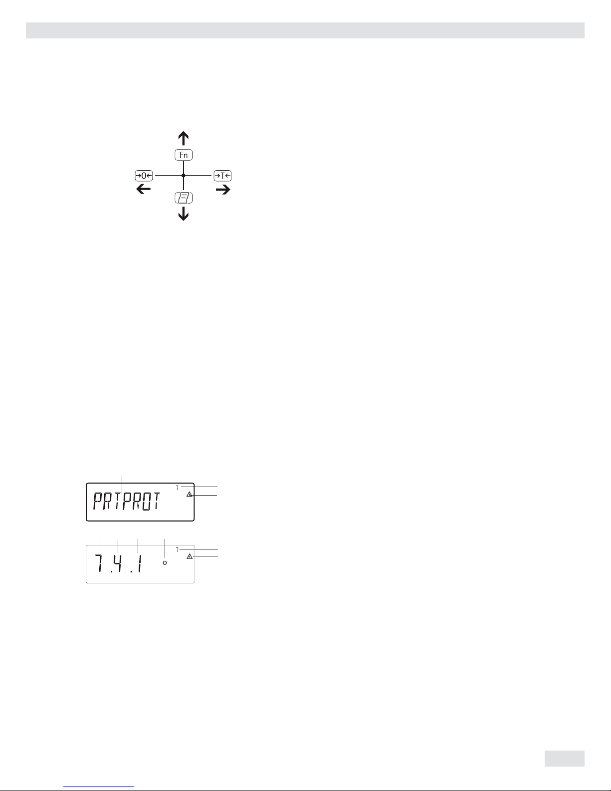
Navigating the Menu
You can navigate the menu using the keys with the white arrows under them.
( Back to the superordinate menu level
k Access the next menu item on the same level.
This continues to page through on the same level.
) Press less than 2 seconds: Select the menu item and save
Press longer than 2 seconds: Exit the menu and switch to weighing mode
p Print the menu settings starting from the current position,
or print Info data
Operating Design
Operating Instructions Combics Indicators 33
Entering Numbers and Letters (without a number block)
( – Press the key less than 2 seconds: Activate character to the left of the
currently active character (when fi rst character is active: exit the input
mode without saving changes)
– Press the key longer than 2 seconds: Exit the input mode without saving
changes
) – Press the key less than 2 seconds:
Confi rm currently active character and move 1 position to the right
(after the last character: Save input)
– Press the key longer than 2 seconds: Save current input and display the
menu item
k – Cursor in fi rst position, no characters changed yet: Delete character(s) and
enter 0
– Change the displayed character; scroll forward (sequence: 0 through 9,
decimal point, minus sign, Z through A, space)
p – Cursor in fi rst position, no characters changed yet: Delete entire string and
enter a space
– Change the displayed character; scroll backwards (sequence: Space,
A through Z, minus sign, decimal point, 9 through 0 )
Number entry for Combics 2:
Enter number values (date and time, etc.) using the 10-key numeric keypad
Menu Display
Both illustrations depict all of the main display elements and symbols that can be
shown in Menu mode.
1 Selected menu item (e.g. printer for setting the connected printer)
2 Menu history (refers to the highest menu level in the Setup menu)
3 Note that other submenus are available
Display with the “codes” language setting
4 First level in the Setup menu
5 Second level in the Setup menu
6 Third level in the Setup menu
7 Current active setting
Saving Menu Settings
The parameters selected in the menu remain saved when you switch to weighing
mode or turn off the device. You can block access to the Setup menu by requiring
a password to prevent unauthorized or accidental setting changes (see page 35).
2
3
4 5 6 7
1
3
2
Operating Design
34 Operating Instructions Combics Indicators
Configuration
Basic settings are made in the Menu mode by selecting the desired parameters.
These are divided into the following groups (menu level 1), menu structure see
page 126:
– Application parameters APPLIC.
– Function key FN-KEY
– Device parameters SETUP
– Device-specifi c information Info
– User language LANGUAG.
When used in legal metrology, not all parameters can be accessed. Only those
parameters that can be selected are displayed. Factory-set parameters are identifi ed
by an “*” in the list starting on page 127.
Printing Parameter Settings
t Access the Menu mode (see page 32)
t Press the p key
The scope of the printout depends on the position in the setup. It may take several
seconds.
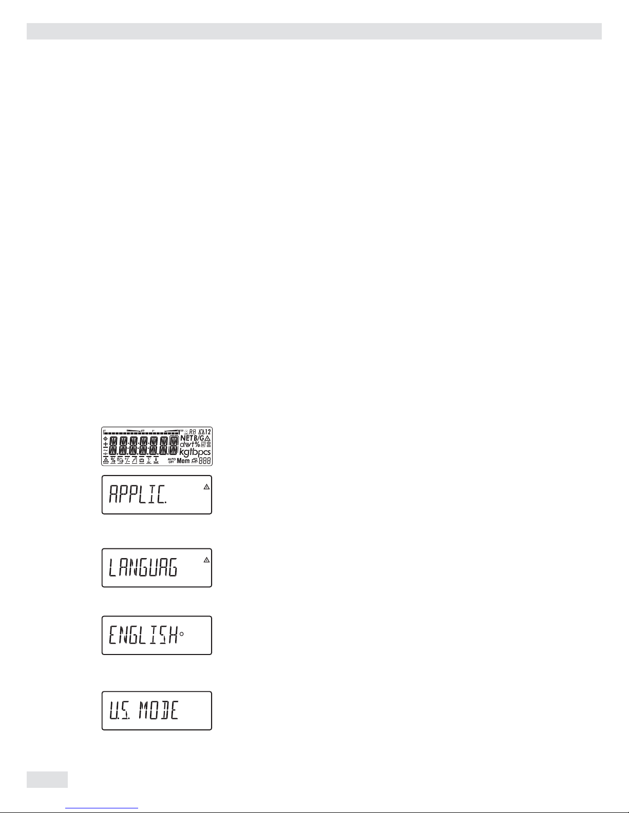
Language, setting
Example: Select the language “German.” The factory setting for language is “English."
Menu: applic. / LANGuag .
e t Turn on the device.
t While all segments are lit, briefl y press the ) key.
y The fi rst item in the main menu is shown: APPLic.
k k ... t Press the k key until the LANGuag menu item appears for the language
setting.
) t Press the ) key to access the language setting sub-menu.
y The currently set language is displayed.
k k ... t Press the k key until u.s. mode is displayed.
) t Press the ) key to save the selection.
Operating Design
Operating Instructions Combics Indicators 35
y The small circle indicates that the setting has been saved.
( Use the ( key to exit the menu level to make additional settings if required
or
) Press the ) key longer than 2 seconds to exit the menu.
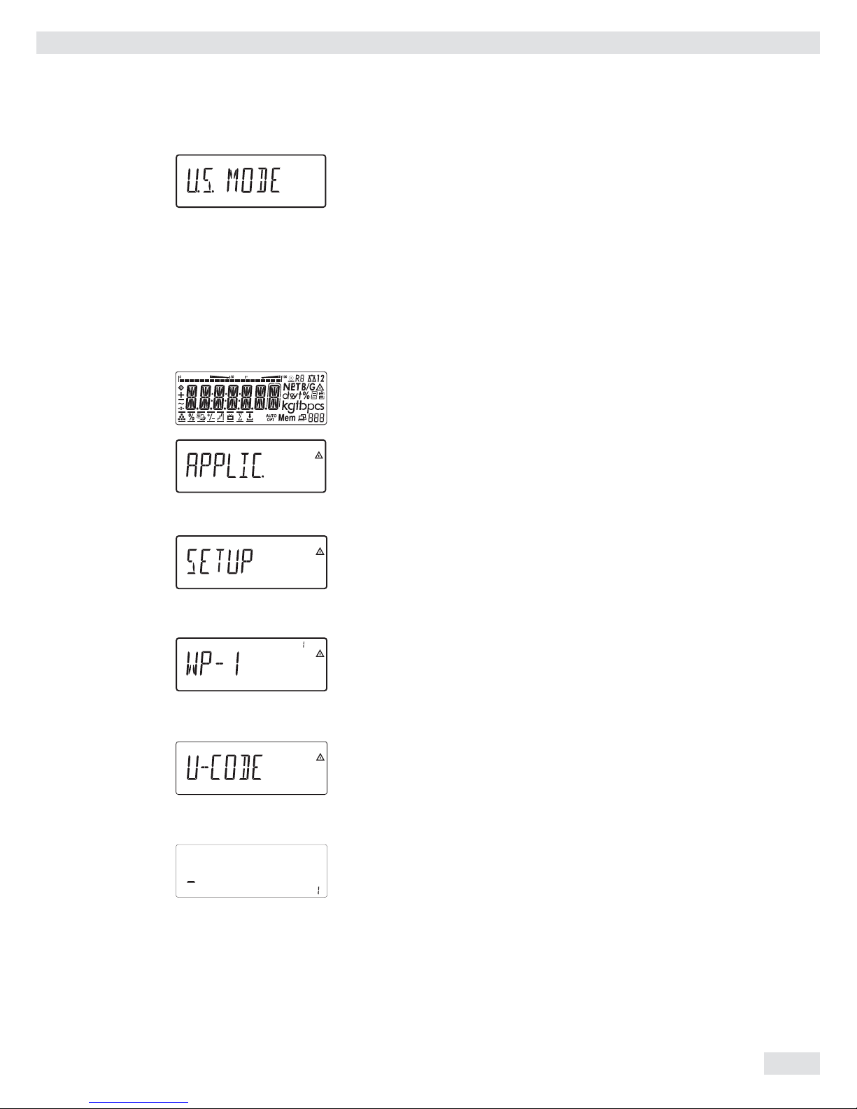
Setting up Password Protection
e t Turn on the device.
t While all segments are lit, briefl y press the ) key.
y The fi rst item in the main menu is shown: APPLIC..
k k ... t Press the k key until the SETUP menu item is displayed.
) t Press the ) key to open the Setup sub-menu.
y The fi rst parameter in the Setup sub-menu is displayed: WP-1.
k k ... t Press the k key until U-CODE is displayed.
) t Press the ) key to open the menu item.
y The position for the fi rst character to be entered fl ashes.
p k t Use the p and k keys to select the desired character.
The p starts the character selection with A alphabetical and the
k key starts the character selection with 0 and counts upward.
Operating Design

36 Operating Instructions Combics Indicators
) t To apply a character, press the ) key.
t Enter all additional characters of the password as described above.
t Press and hold the ) key to save the password.
( Use the ( key to exit the menu level to make additional settings if required
or
) Press the ) key longer than 2 seconds to exit the menu.
Changing or Deleting Passwords
t Open the U-CODE menu item in the SETUP menu as described above.
y The old password must be entered to change or delete a password.
t To change a password, overwrite the old password.
t To delete a password, enter spaces and press the ) key.
Operating Design

Operating Instructions Combics Indicators 37
Operation
Weighing
This application is always available during operation.
Features: – Zeroing by pressing (
– Storing the weight on the platform as a tare by pressing )
– Tare container weight automatically
– Use a barcode scanner to enter tare weight (Combics 2)
– Use a 10-key keypad to enter tare weight (Combics 2)
– Delete tare values using the numeric entry 0 and ) / c and )
(Combics 2)
– Toggle the display using k between:
– Combics 1: Gross and net values
– 1st and 2nd weight unit or
– Combics 1: Normal and 10-fold higher resolution
– Weighing with two weighing platforms (for Combics 2 only)
– Individual numeric ID codes for weight values (Combics 2)
– Print weight value:
– GMP-compliant printout
– Automatic printout
– Automatic data output (see Data Interfaces chapter)
Automatic taring (APPLIC. menu item 3.7):
When the menu item is active (3.7.2), the fi rst weight on the scale that exceeds the
preset minimum load is stored in the tare memory at stability.
The scale returns to the initial state when the load on the scale is less than 50% of
the minimum load.
Minimum load for automatic taring and automatic printing
(menu item 3.5):
You can set the following for the minimum load:
1 digit (no minimum load)
2 digits
5 digits
10 digits
20 digits
50 digits
100 digits
200 digits
500 digits
1000 digits
The “digits” here refer to the scale intervals for the connected weighing platform.
If the interval is 1 g and 1000 digits are required, the minimum load is 1000 g
(1000 intervals).
If the weighing platform interval is 5 g and the same number of digits as above are
required, the minimum load is 5000 g.
When the load exceeds the minimum load limit, the weighing platform is tared
automatically and/or a report printout is generated automatically; however, this
requires the corresponding menu items are active for automatic taring (menu item
3.7.2) and for automatic printing (menu 7.15.2).
Operation

38 Operating Instructions Combics Indicators
Automatic printing (PROTOC menu item 7.15):
When the menu item (7.15.2) is active, the fi rst weight value that exceeds the
minimum load is printed.
If the menu item is also activated for automatic taring, it is only tared when the
minimum load is exceeded. In this case, an automatic printout would only be
generated when the second weight value exceeds the minimum load.
Main scale: first platform displayed on start-up (Combics 2 only)
You can select the weighing platform to be displayed fi rst when Combics is turned
on in the Setup menu under “UTILIT.” (menu item 8.11.).
Entering a tare weight using a barcode scanner (Combics 2 only)
The tare weight of the container can be entered via a barcode scanner. To do this,
the Tare setting must be activated in the menu under Setup/Barcode.
The value is applied and saved automatically, the t key does not have to be
pressed. The content of the tare memory can be displayed in Info mode (I key).
Entering the wRef application parameter using a barcode scanner
(Combics 2 only)
wRef application parameters can be entered via a barcode scanner. To do this, the
wref setting must be activated in the menu under Setup/Barcode. The value is
applied and saved automatically, the r key does not have to be pressed.
Entering Identifier using a barcode scanner (Combics 2 only)
Identifi ers can be entered via a barcode scanner.
ID1: To do this, the ID1 setting must be activated in the menu under
Setup/Barcode. The value is applied and saved automatically, the
d key does not have to be pressed.
ID2 to ID6: To do this, the HEADER setting must be activated in the menu under
Setup/Barcode. Then press the d key until the desired ID entry
appears, scan the barcode and save.
Displaying the content of the identifiers:
– d key
Scanning barcodes directly
You can directly scan a barcode using the barcode scanner.
Menu setting: Setup / BARCODE/ INPUT
The barcode can contain the following codes:
- I for write identifi er
- T for save tare memory
- R for write reference weight
- A for activate product data memory
Examples: “I4Anton" = write the character string to ID 4: Anton
“TC1" = write 1 Kg to the preset tare memory.
“C” = unit: Kilograms
“B” = grams
“D” = carat,
etc.
“RC0.0023" = write 0.0023 kg as the reference weight
“A1" = load product data memory 1
Menu setting: Setup /BARCODE / HEADER
The characters read from the barcode are shown in the weight value display.
Operation

Operating Instructions Combics Indicators 39
Adjustment/Configuration Counter for Standard Scales
Purpose Automatic recording of changes to adjustment and weighing parameters using two
independent counters. The values remain saved for the life of the component.
t To display both counters, press and hold the ( key for longer than 2 seconds.
y The “Confi guration counter” is then shown in the weight display for 3 seconds
(identifi ed by a P). Then the “Adjustment counter” is displayed for another
3 seconds (identifi ed by a C). After 6 seconds, the information display turns off
automatically.
Adjustment Counter Features: – Counter limited to 9999
– Counter at “C 0000” for hardware commissioning
– Counter cannot be reset
– Counter is updated automatically when:
– linearization, calibration/adjustment is successful
– user calibration, adjustment or linearization weight is changed (menu 1.18.)
– When the following parameters are changed:
Function of the q key (menu item 1.9.)
Zero setting range (menu item 1.11)
Tare/zero at power on (menu item 1.12)
The above parameters are reset to factory settings (menu item 9.1.1)
Configuration Counter Features: – Counter limited to 9999
– Counter at “P 0000” for hardware commissioning
– Counter cannot be reset
– Counter is updated automatically when:
– When the following parameters are changed:
Installation location (menu item 1.1.)
Application fi lter (menu item 1.2.)
Stability range (menu item 1.3.)
Taring (menu item 1.5)
Auto zero (menu item 1.6.)
Weight unit 1 (menu item 1.7.)
Weight unit 2 (menu item 3.1.)
Weight unit 3 (menu item 3.3.)
The above parameters are reset to factory settings (menu item 9.1.1)
– Switching the k key to or from a 10-fold higher resolution
– Turning the application automatic taring on/off
(menu item 3.7.)
– The application parameters are reset to factory settings
(menu item 9.1.1)
Operation

40 Operating Instructions Combics Indicators
Device Parameters
Password protection
Access to the device parameters Setup and application parameters APPLIC.
(Combics 2) can be password-protected against unauthorized changes in the Setup
menu under U-CODE (see page 35).
Acoustic signal
An acoustic signal (single beep for active, double beep for inactive keys) is emitted
when you press a key.
In the SETUP menu, the acoustic signal can be turned on/off under UTILIT. /
PARAMET(ER) / SIGNAL (menu item 8.2.).
Keypad
The keypad can be blocked/released for entry in the SETUP menu under UTILIT. /
PARAMET(ER) / KEYS (menu item 8.3.).
Automatic shutoff of Combics
In the SETUP menu, the indicator can be shut off automatically using a timer under
UTILIT. / PARAMET(ER) / AUTO.OFF (menu item 8.7.).
Display lighting
The following settings can be made for display lighting in the SETUP menu under
UTILIT. / PARAMET(ER) / BACKLIT:
– on (8.8.1)
– off (8.8.2)
– off automatically using a timer (8.8.3)
Timer
The timer for turning off the device and/or display lighting can be set to 2, 4, or
10 minutes in the SETUP menu under UTILIT. / PARAMET(ER) / TIMER (menu
item 8.9.)
Example: Switch on the device, zero the scale, tare the container weight, place sample in the
container, toggle display to gross weight or to second weight unit or 10-fold
resolution
e t Turn on the device.
t All display segments appear (display test).
y The display for no load on the scale appears.
( t Press the ( key to zero the scale.
y The display for a zeroed scale appears.
Operation

Operating Instructions Combics Indicators 41
t Place the container on the weighing platform.
y The container weight is displayed.
) t Press the ) key to tare the scale.
y The display for a tared scale with a container appears.
t Place a sample in the container (in this example 120.2 g)
y The display for a tared scale with weighing results appears.
k t Press the k key to toggle the display.
y The following is displayed depending on the confi guration:
y The gross weight (in this example, 170.2 g = 50 g for container + 120.2 g for
sample) (Combics 1)
or
y Weight value display in 2nd weigh unit (in this example kg)
or
y Weight value display with 10-fold resolution
This display switches back automatically after 10 seconds.
(Combics 1)
k t Press the k key to return to the previous display.
Operation

42 Operating Instructions Combics Indicators
y Net weight value display before it was switched.
p t Press the p key to print a report.
ACE HARDWARE
GOETTINGEN
12.08.2010 15:10 Date and time for Combics 2 only
--------------------
G# + 170.2 g
T + 50.0 g
N + 120.2 g
--------------------
Example Combics 2: Weighing: Enter value for tare using the numeric keys; print results.
e t Turn on the device.
t All display segments appear (display test).
y The display for no load on the scale appears. When Combics 2 is turned on,
it ready for weighing and zeros itself automatically.
With no load on the scale, you can zero the weighing platform at any time by
pressing (.
250 t Enter the tare weight in the current weight unit using the keypad (e.g., 250 g).
) t Press the ) key to save the tare value.
t Place the container on the scale.
y The net weight value is displayed.
L t Press the L key to display the gross weight.
Operation

Operating Instructions Combics Indicators 43
y The gross value is displayed.
You can toggle between the gross and net display using the L key.
p t Press the p key to print a report.
-------------------- GMP header (only if GMP-compliant
printout is configured,
24.08.2010 15:15 menu 7.13)
Type CW1NP1-30ED-LCE
Ser.no. 12345678
Vers. C2 100.200810
BVers. 01-62-01
-------------------- End of GMP header
ACE HARDWARE Headers
GOETTINGEN
BATCH NO. 123456 Identifier 1
CUSTOMER 6.789 Identifier 2
24.08.2010 15:15
--------------------
G# + 2250 g
T + 0000 g
PT2 + 250 g
N + 2000 g
--------------------
-------------------- GMP footer (only if GMP-compliant
printout is configured)
24.08.2010 15:16
Name:
-------------------- End of GMP footer
0 + ) To delete the tare weight, enter 0 using the number block and press ).
Operation

44 Operating Instructions Combics Indicators
Calibration and Adjustment
Purpose Perform calibration to determine the difference between the value displayed and
the actual weight on the platform. Calibration does not entail making any changes
within the weighing equipment.
During adjustment, the difference between the measured value displayed and the
true weight of a sample is corrected, or is reduced to an allowable level within
maximum permissible error limits.
Configuration for Use in Legal Metrology
Confi guration of the weighing instrument for use in legal metrology is set by a
switch. The switch is located on the back of the weighing platform and covered by a
protective cap.
Using a verifi ed scale in legal metrology in the EU:
The Type-Approval Certifi cate for verifi ed scales is only valid for non-automatic
weighing instruments. For automatic operation with or without additional,
integrated equipment, please follow the applicable national regulations for the
installation location.
Externally Connected IS Scales: Before use in legal metrology, the scale should be calibrated via the internal
calibration equipment at the installation location: see the “Internal Calibration”
section in this chapter.
3
The temperature range (°C) listed on the ID label should not be exceeded during
operation.
For Servicing: External calibration for verifi ed scales of accuracy class l
– External calibration is blocked in legal metrology (switch cover is sealed)
– External calibration is only possible by removing the seal. If the seal is broken,
the validity of verifi cation will become void and you must have your scale
re-verifi ed.
Using a verifi ed scale in legal metrology with internal calibration equipment:
t Before use in legal metrology, the “internal calibration” function should be
carried out at the installation location:
Opening the Menu Access Switch
The menu access switch is located on the back of the indicator right next to the
weighing platform connection.
t Remove the cap.
t Slide the switch to the left (= “open” position, for use in legal metrology).
Operation

Operating Instructions Combics Indicators 45
Features Which of the following features are available depends on the connected weighing
platform. These features are confi gured in the Setup menu:
– External calibration/adjustment blocked in verifi ed weighing instruments
– External calibration/adjustment with the default weight value or user-defi ned
weight (not available on verifi ed instruments):
setup / wp-1/ param.1 /CAL./ADJ.menu “Calibration, Adjustment."
– Specify the weight for external calibration/adjustment:
setup / wp-1 / param.1 / man.ext.w menu “Entering Calibration Weight"
– Internal adjustment for IS weighing platforms (confi gure under: COM1 or
unicom / WP2), Combics 2
– Block the J key to prevent use of the two functions described above:
setup / wp-1 “Calibration, Adjustment."
– Calibrate fi rst; then adjust automatically or manually (not for verifi ed weighing
instruments): setup / wp-1/ param.1 / Cal.routine"Calibration/Adjustment
sequence"
– Flashing n symbol as adjustment prompt. If more than one weighing
platform is connected, the platform number is also displayed: setup / wp-1
menu Menu item 1.15. “Adjustment prompt"
– Block external calibration/adjustment: setup / wp-1/ param.1 / EXT.Cal.
menu “External calibration."
Example: External Calibration and Manual Adjustment with Default Weights (weighing
parameters: factory settings)
Operation
( 1.) Zero the scale.
J 2.) Start calibration
(e.g., when adjustment
prompt fl ashes WP).
cal.Ext. is displayed for
two seconds.
You are prompted to place
the required weight on the
platform (e.g., 10,000 g).
3.) Position the calibration/
adjustment weight on the
weighing platform.
The difference between the
measured value and the
true weight of the sample
will be displayed with plus/
minus signs.
Ext. calibration Printout is generated,
Nom. + 10000 g if the process was cancelled
Diff. + 1 g with (
J 4.) Activate calibration/
adjustment (press the (
key to cancel).
The adjustment weight is
displayed once adjustment
is fi nished.
-------------------- A GMP-compliant printout
24.02.2010 10:15 is generated.
Type CAW2S
Ser.no. 12345678
Vers. 1.0103.11.2
BVers. 01-26-02
-------------------Ext. calibration
Nom. + 10000 g
Diff. + 1 g
Ext. adjustment
Diff. + 0 g
--------------------
24.02.2010 10:15
Name:
--------------------

46 Operating Instructions Combics Indicators
Internal Calibration/Adjustment for CAH Models...
System Requirements – “Internal Calibration” must be set in the Setup menu: setup / wp-1/ param.1 /
CAL./ADJ. / Cal.Int.
– The scale housing has a built-in motorized calibration weight.
Example: Internal calibration and then adjustment (weighing parameters: factory settings
for CAH... models)
Operation
( 1.) Zero the scale.
J 2.) Start calibration
(e. g., when adjustment
prompt fl ashes WP).
cal.Int. is displayed for
two seconds.
y The internal calibration
weight is loaded
automatically.
The difference between
the measured value and
the true weight of the
sample will be displayed
with plus/minus signs.
Internal calibration A printout will be
Diff. + 0.2 g generated if the process
is cancelled using the
( key.
J 3.) Activate calibration/
adjustment (press the (
key to cancel).
The adjustment weight is
displayed once adjustment
is fi nished.
-------------------- A GMP-compliant
24.11.2010 10:13 printout is generated.
Type CAH1E-34ED-H
Ser.no. 27163010
Vers. C2 101.081210
BVers. 01-62-01
--------------------
Internal calibration
Diff. + 0.2 g
Internal adjustment
Diff. + 0.0 g
--------------------
24.11.2010 10:15
Name:
--------------------

Operating Instructions Combics Indicators 47
SQmin Function
Purpose To display the allowable minimum sample quantity “SQmin” (sample quantity
minimum) in accordance with the United States Pharmacopoeia (USP). According to
USP guidelines, the uncertainty of measurement may not exceed 0.1% of the sample
quantity when substances are weighed with the highest degree of accuracy for
volume determination. This additional function ensures that weighing results lie
within defi ned tolerance limits corresponding to the requirements of your quality
assurance system.
System Requirements The scale must be set up by a service technician to be able to use the SQmin
function. The technician will determine the permitted minimum sample quantity
and load this to your scale using the guidelines of your QA system. He will document
this setting via a “Weighing module test as per USP” certifi cate in which the
measurements and min. sample quantity are logged. The SQmin function ensures
that the weighing results correspond to USP guidelines. These SQmin settings
cannot be changed by the user.
Features – Displaying the minimum sample quality: The value is displayed in the text line
for 4 seconds after pressing the k key.
– If the minimum sample quantity has not been reached: The k symbol is
displayed and weight values are marked with a “!” in the printout.
– GLP header: The minimum sample quantity entered for SQmin can be included
on the printout.
Setting SQmin parameters
The SQmin display must be turned on to use the SQmin function.
Menu: SETUP / SQMIN /
SQmin display: DISPLAY yes/no*
Print in GLP header: GMP PRT. yes/no*
* = Factory setting
SQmin Operation
Example Determining sample weights while monitoring the minimum sample quantity
(in this example, SQmin = 100 g)
Confi guration: The SQmin display must be turned on.
) t Place the container for the sample on the scale and tare.
t. Place the sample on the scale.
y The minimum sample quantity is not reached (symbol k).
p t Print the weight value.
| N + 90.0 ! |
t Place another sample on the scale.
Operation

48 Operating Instructions Combics Indicators
y The minimum sample quantity is exceeded.
p t Print the weight value.
| N + 110.0 g |
k t Briefl y press the k key to toggle between the measured value and SQmin
value.
y The value for the minimum sample quantity is displayed for four seconds.
Data ID Codes
This function is only available for Combics 2.
You can assign codes (such as product name, batch number, etc.) for identifi cation
of measured values on printouts.
Features – Assign up to six ID codes.
– Assign both a name and a value to each ID code.
– Displaying individual IDs: press the d key
– The name is left-justifi ed and the value is right-justifi ed on the printout.
If the entire code is too long for one line, additional lines are printed.
– Enter ID code names in the Setup menu under:
SETUP / PRTPROT , menu item 7.4.
The name can have a max. of 20 characters.
– Enter up to 40 characters for the value of the ID code. Press the d key to
activate the input mode.
– Individual characters of the ID can be deleted using the c key.
– If both the name and value fi elds are empty, no ID code is printed.
– In the Setup program, you can confi gure when and whether ID codes are printed
(see “Configuring Printouts” page 93).
Settings for individual ID codes
Menu: SETUP / PRINT/PROTOC. / HEADlin.
Factory settings for ID code names:
ID1: ID1
ID2: ID2
ID3: ID3
ID4: ID4
ID5: ID5
ID6: ID6
There are no factory settings for ID code values.
Operation

Operating Instructions Combics Indicators 49
Using Individual ID Codes
Example Enter ID code names. “Batch number” and “Customer” should be entered for ID 1
and ID 2.
e ... ) t Open menu (see page 32) .
k k ... ) t Select and open SETUP.
k k ... ) t Select and open PRINT.
) t Open PROTOC..
) t Open HEADLIN. .
k k ... ) t Select and open ID 1.
k p ... t Enter a name for the fi rst ID (using the k and p keys or use the number
block), e.g. “batch number."
) t To save the entry, press the ) key.
k ... ) t Select and open ID 2.
k p ... t Enter a name for the 2nd ID, e.g. “customer."
) t To save, press the ) key.
( ( ... t To exit the sub-menu, press the ( key several times.
Operation

50 Operating Instructions Combics Indicators
Application Programs
Overview of Applications and Functions
Combics 1 Combics 2
Keys 6 keys 17 keys plus
numeric keypad
Display 14-segment 14-segment plus
pictograms
Application
Basic weighing X X
Send print job/data record to
peripheral device X X
Label printer X X
Connection option for second scale – X
Counting – X
Neutral measurement – X
Averaging (animal weighing) – X
Weighing in percent – X
Checkweighing – X
Classification – X
Totalizing – X
Batching/Counting to target value – X
Product data memory – X
Function
Zero X X
Tare X X
Date/time – X
Internal battery (rechargeable) Optional Optional
ID codes (6 codes, 40 characters each) – X
Barcode – Optional
Automatic printout X X
Automatic taring X X
Manual taring – X
Analog data output Optional Optional
Selectable control inputs X X
Electronically isolated control inputs
and outputs Optional Optional
Unit conversion X X
Increased resolution X X
GMP-compliant printout X X
h
Combination of applications see page 90.
Operation

Operating Instructions Combics Indicators 51
Counting Z (Combics 2):
With the Counting application, you can determine the number of parts which each
have approximately equal weight (APPLIC.1 menu).
Features – Save the reference weight “wRef” from the weighing platform
– Enter the average piece weight “wRef” via the keypad
– Enter the reference sample quantity “nRef” via the keypad
– Enter reference sample weight using a barcode scanner
– Automatic reference sample updating
– Counting with two weighing platforms
– Activate Info mode via the I key
– Toggle the display between quantity and weight via the W key
– Defi ne the level of accuracy (display resolution) applied when a calculated
reference sample quantity is saved
– Automatic taring of container weight.
Setting: Applic. / aut.tare, menu item 3.7
– Automatic initialization when the scale is switched on. The indicator is
initialized with the most recently used values for reference sample quantity
“nRef” and reference sample weight “wRef.”
Setting: Applic. / aut.strt, menu item 3.8
Exit application, delete parameters
The value of the reference sample weight in the reference memory remains active
until it is deleted via the c key or overwritten or until the application is changed.
The reference sample weight also remains saved after the scale is turned off.
You can assign different functions to the c key for deleting applications.
When you clear applications, you can delete either the data stored for all
applications or just selected data stored for the active application.
Setting: Applic. / CLER.CF menu item 3.24
Tare function:
If you store a tare (weight value) by pressing the ) key, you can later enter
a tare value manually. The tare value you enter is added to the stored tare value.
Setting: Applic. / TARE.FNC menu item 3.25.1 (factory setting)
A tare value entered manually overwrites a stored tare value (weight value).
If you enter a tare value manually, a tare value (weight value) stored later overwrites
the manually entered value. Setting: Applic. / TARE.FNC menu item 3.25.2
Restore factory default settings: Applic./Reset menu item 9.1.
Average piece weight
Before the quantity on the platform can be calculated, the average piece weight
must be entered in the application. There are several ways to enter this value in the
program:
Calculating the reference piece weight
– Place the number of parts defi ned as the reference sample quantity on the
weighing platform and calculate the average piece weight by pressing the
O key.
or
– Place any number of parts on the connected weighing platform, enter the
quantity using the keypad and select and calculate by pressing the r key.
How the reference weight is calculated depends on the application setting for
resolution. The value is either rounded off in accordance with the display resolution,
or saved with 10-fold or 100-fold resolution.
Operation

52 Operating Instructions Combics Indicators
Entering the reference piece weight
The reference piece weight (i.e., the weight of one piece) can be entered using the
keypad and save with the O key.
Reading the reference piece weight
The reference piece weight can be read using a barcode scanner.
h
The entered value remains active until deleted by pressing the c key or until
overwritten by a new value. It remains saved after the scale is switched off.
Preparation t Open the APPLIC. / APPLIC.1 / COUNT. menu.
Available Parameter Settings * = Factory setting
MIN.INIT Minimum load for initialization 3.6
1 digit 1 digit* 3.6.1
2 digit 2 digits 3.6.2
5 digit 5 digits 3.6.3
10 digT. 10 digits 3.6.4
20 digT. 20 digits 3.6.5
50 digT. 50 digits 3.6.6
100 diG. 100 digits 3.6.7
200 diG. 200 digits 3.6.8
500 diG. 500 digits 3.6.9
1000 dI. 1000 digits 3.6.10
RESOLUT Resolution for calculation of reference value 3.9.
DISP.ACC Display accuracy* 3.9.1
10 FOLD Display accuracy + 1 decimal place 3.9.2
100FOLD Display accuracy + 2 decimal places 3.9.3
SAVE WT. Parameter for saving weight values 3.11
STABIL. With stability* 3.11.1
ACC.STAB With increased stability 3.11.2
REF.UPDT Reference sample updating . 3.12.
OFF Off 3.12.1
automat Automatic* 3.12.3
REF.WP Reference weighing instrument 3.13.
NO WP No weighing platform selected 3.13.1*
wp 1 Weighing platform WP1 3.13. 2
wp 2 Weighing platform WP2 3.13. 3
) �t To save the setting, press the ) key.
( ( ... t To exit setup: Press the ( key several times.
Minimum Load for Initialization You can set the minimum load here, i.e. the load that must be placed on the
weighing platform in order to carry out the application. If the load on the platform
is too light, the following will occur:
– Error code Inf 29 appears,
– The weighing platform is not initialized,
– The preset reference sample quantity is saved.
Setting: Applic./Applic.1/Count./Min.init menu item 3.6.
The minimum load can be set in 10 steps from 1 to 1000 digits (see available
parameters). The “digits” here refer to the scale intervals for the connected weighing
platform. If the interval of the connected platform is 1 g, for example, and 1000 digits
are required, you must place at least 1000 g (= 1000 intervals = 1000 digits) on the
weighing platform for initialization.
Operation

Operating Instructions Combics Indicators 53
Resolution The resolution indicates the accuracy used to determine the reference weight.
The default setting is “display resolution.” The resolution is increased when “10fold” or “100-fold” is selected. “10-fold” increases the resolution of the net value
by one step (display resolution x 10), “100-fold” increases it two steps (display
resolution x 100).
Setting: Applic./Applic.1/Count./RESOLUT menu item 3.9.
Parameter for Saving Weight Values The weight on the platform is saved as a reference value as soon as the platform has
stabilized. “Stability” is defi ned as the point at which the fl uctuation of a measured
value lies within a defi ned tolerance. The narrower the tolerance, the more stable the
platform is at “stability”.
The “increased stability” setting has a lower tolerance so that the average piece
weight saves is more accurate and the results more reproducible; however, the
measurement time can take longer.
Setting: Applic./Applic.1/Count./SAVE WT. menu item 3.11.
Reference Sample Updating You can defi ne whether or not the reference sample weight is updated automatically
during weighing using this setting. The reference sample weight is updated
automatically only when the following criteria are met:
1. “Automatic” must be set for reference sample updating in the menu.
2. The current piece count exceeds the original piece count by at least two.
3. The current piece count cannot be more than double the size of the original
piece count. This limitation does not apply to the fi rst update if the piece weight
was entered via a barcode scanner or keypad.
4. The current piece count is less than 1000.
5. The internally calculated piece count (such as 17.24 pcs) differs by less than
± 0.3 pcs from the nearest whole number (in this example: 17).
6. The weighing platform is stable in accordance with the parameter defi ned for
saving weights.
If automatic reference sample updating is selected in the menu and the piece count
(pcs) is displayed, the Auto symbol is displayed below the bar graph. If the average
piece weight has been updated since you began weighing, the text line shows the
0pt symbol. During an updating operation, 0pt and the updated piece count are
displayed briefl y in the measured value line. The new reference sample weight and
reference sample quantity are saved.
Setting: Applic./Applic.1/Count./REF.UPDT menu item 3.12.
Counting with Two Weighing Platforms You can use two weighing platforms simultaneously with the Counting application.
When using two platforms, you can choose from the following operating modes:
– Counting with two platforms of the same type
– Counting with one reference platform and one weighing platform
Counting with two platforms of the same type
Use this mode to count different types of sample material with different weights.
For example, count the lighter-weight pieces on one platform and the heavier pieces
on another. You can defi ne one of the two scales as the reference scale.
The reference scale is the fi rst scale active when you switch on the device, regardless
of the setting for automatic initialization of the Counting application.
Counting with one reference platform and one weighing platform
In this operating mode, the reference platform is a high-resolution weighing
platform with a relatively low maximum capacity. The other platform is used for
weighing heavier samples, and has a high capacity with a relatively low resolution.
This allows you to both determine the reference sample weight with high resolution;
i.e., very precisely, and to count large amounts of parts, without requiring an
expensive high-resolution, high-capacity weighing platform.
Operation

54 Operating Instructions Combics Indicators
The system can be confi gured to switch automatically to the reference platform for
initialization (the measured value line shows Ref). Following initialization, you can
switch to the counting platform.
Setting: Applic./Applic.1/Count./REF.WP menu item 3.13.
h
If automatic reference sample updating is enabled, the update is performed on the
active platform; in other words, the system does not automatically switch to the
reference platform.
Example: You need to determine an unknown number of parts and the measurements should
be logged.
Confi guration: The “Counting” application is selected, and printout has been set up.
t Place empty container on the scale.
) t Tare the scale.
This is not required if the automatic tare function is active. The tare weight is
saved automatically when you place the container on the platform.
t Place a number of parts in the container for the reference quantity (in this
example, 20 pcs).
2 0 t Enter the number of parts using the keypad.
r t Start the calculation of the reference piece weight.
r t Set the number of reference parts using r: 1, 2, 5, 10, 20, etc.
O t Start the calculation of the reference piece weight.
Operation

Operating Instructions Combics Indicators 55
t Add a quantity of uncounted parts to the container.
y The result is displayed.
y If automatic reference sample updating is enabled, Opt appears in the display.
p t Print results (Confi guring Printouts see page 93).
nRef + 38 pcs
wRef + 0.003280 kg
G# + 0.373 kg
T + 0.248 kg
N + 0.125 kg
Qnt 38 pcs
--------------------
Operation

56 Operating Instructions Combics Indicators
Neutral Measurement Z nM (Combics 2)
With this application you can measure the length, surface and volume of parts that
have roughly the same specifi c weight. The o symbol is displayed as the unit (menu
APPLIC.1).
Features – Save the reference weight “wRef” from the weighing platform:
– Enter the reference weight “wRef” through the keypad
– Enter the factor for calculation “nRef” using the keypad
– Enter reference sample weight using a barcode scanner
– Measuring with two weighing platforms
– Activate Info mode with the I key
– Toggle the display between measurement and weight via the w key
– The level of accuracy (display resolution) can be set when the calculated
reference weight is applied
– Automatic taring of container weight
Setting: Applic. / aut.tare, menu item 3.7
– Automatic initialization when the scale is switched on. The indicator is
initialized with the most recently used values for reference sample quantity
“nRef” and reference sample weight “wRef.”
Setting: Applic. / aut.strt, menu item 3.8
Exit application, delete parameters
The value of the reference sample weight in the reference memory remains active
until it is deleted via the c key or overwritten or until the application is changed.
The reference sample weight also remains saved after the scale is turned off.
You can assign different functions to the c key for deleting applications. When
you clear applications, you can delete either the data stored for all applications or
just selected data stored for the active application.
Setting: Applic./CLER.CF menu item 3.24
Tare function:
If you store a tare (weight value) by pressing the ) key, you can later enter a tare
value manually. The tare value you enter is added to the stored tare value.
Setting: Applic. / TARE.FNC menu item 3.25.1 (factory setting)
A tare value entered manually overwrites a stored tare value (weight value). If you
enter a tare value manually, a tare value (weight value) stored later overwrites the
manually entered value.
Setting: Applic. / TARE.FNC menu item 3.25.2
Restore factory default settings: Applic./Reset menu item 9.1.
Reference weight
In order to calculate the length, surface or volume of a given sample, the average
weight of a reference quantity of the sample must be known (in the example below,
the reference is 1 meter of electrical cable). There are different ways to enter the
reference weight:
Calculating the reference weight
– Place the reference quantity (defi ned by the calculation factor) on the connected
weighing platform and calculate the reference sample weight by pressing the
O key.
or
– Place any amount of the sample material on the connected weighing platform,
enter the calculation factor through the keypad, and press the r key to
calculated reference sample weight.
Operation

Operating Instructions Combics Indicators 57
How the reference weight is calculated depends on the application setting for
resolution. The resolution settings are either display resolution, display resolution
10-fold or display resolution 100-fold.
Entering the reference weight
The reference weight (e.g., the weight of one meter of electrical cable) can be
entered using the keypad and saved by pressing the O key.
Reading the reference piece weight
The reference weight can be read using a barcode scanner.
h
The entered value remains active until deleted by pressing the c key or until
overwritten by a new value. It remains saved after the scale is switched off.
Preparation t Open the APPLIC. / APPLIC.1 / Neutr.M menu.
Available Parameter Settings * = Factory setting
MIN.INIT Minimum load for initialization 3.6
1 digit 1 digit 3.6.1*
2 digit 2 digits 3.6.2
5 digit 5 digits 3.6.3
10 digT. 10 digits 3.6.4
20 digT. 20 digits 3.6.5
50 digT. 50 digits 3.6.6
100 diG. 100 digits 3.6.7
200 diG. 200 digits 3.6.8
500 diG. 500 digits 3.6.9
1000 dI. 1000 digits 3.6.10
RESOLUT Resolution for calculation of reference value 3.9.
DISP.ACC Display accuracy 3.9.1*
10 FOLD Display accuracy + 1 decimal place 3.9.2
100FOLD Display accuracy + 2 decimal places 3.9.3
DEC.PLCS Decimal places in displayed result 3.10
NONE None 3.10.1*
1 DEC.PL 1 decimal place 3.10.2
2 DEC.PL 2 decimal places 3.10.3
3 DEC.PL 3 decimal places 3.10.4
SAVE WT. Parameter for saving weight values 3.11
STABIL. With stability 3.11.1*
ACC.STAB With increased stability 3.11.2
REF.WP Reference weighing instrument 3.13.
NO WP No weighing platform selected 3.13.1*
wp 1 Weighing platform WP1 3.13.2
wp 2 Weighing platform WP2 3.13.3
) �t To save the setting, press the ) key.
( ( ... t To exit setup: Press the ( key several times.
Operation

58 Operating Instructions Combics Indicators
Minimum Load for Initialization You can set the minimum load here, i.e. the load that must be placed on the
weighing platform in order to carry out the application. If the load on the platform
is too light, the following will occur:
– Error code Inf 29 appears,
– The weighing platform is not initialized,
– The preset reference sample quantity is saved.
Setting: Applic./Applic.1/neutr.m/Min.init menu item 3.6.
The minimum load can be set in 10 steps from 1 to 1000 digits (see available
parameters). The “digits” here refer to the scale intervals for the connected weighing
platform. If the interval of the connected platform is 1 g, for example, and 1000
digits are required, you must place at least 1000 g (= 1000 intervals =1000 digits)
on the weighing platform for initialization.
Resolution The resolution indicates the accuracy used to determine the reference weight.
The default setting is “display resolution.” The resolution is increased when
“10-fold” or “100-fold” is selected. “10-fold” increases the resolution of the net
value by one step (display resolution x 10), “100-fold” increases it two steps
(display resolution x 100).
Setting: Applic./Applic.1/neutr.m/RESOLUT menu item 3.9.
Decimal Places In neutral measurement, not only whole numbers but also decimal numbers
(for example, 1.25 o electrical cabling) can be displayed. The number of decimal
places displayed can range from none up to 3 places.
Setting: Applic./Applic.1/neutr.m/DEC.PLCS menu item 3.10.
Parameter for Saving Weight Values The weight on the platform is saved as a reference value as soon as the platform has
stabilized. “Stability” is defi ned as the point at which the fl uctuation of a measured
value lies within a defi ned tolerance. The narrower the tolerance, the more stable the
platform is at “stability”.
The “increased stability” setting has a lower tolerance so that the average piece
weight saves is more accurate and the results more reproducible; however, the
measurement time can take longer.
Setting: Applic./Applic.1/neutr.m/SAVE WT. menu item 3.11.
Measuring with Two Weighing Platforms You can use two weighing platforms simultaneously with the Neutral Measurement
application. When using two platforms, you can choose from the following
operating modes:
– Counting with two platforms of the same type
– Counting with one reference platform and one weighing platform
Neutral measurement with two weighing platforms
Use this mode to measure different types of sample material with different weights.
For example, measure the lighter-weight samples on one platform and the heavier
samples on another. You can defi ne one of the two scales as the reference scale.
The reference scale is the fi rst scale active when you switch on the device, regardless
of the setting for automatic initialization of the Neutral Measurement application.
Neutral measurement with one reference platform and one weighing platform
In this operating mode, the reference platform is a high-resolution weighing
platform with a relatively low maximum capacity. The other platform is used for
weighing heavier samples, and has a high capacity with a relatively low resolution.
This allows you to both determine the reference piece weight with high resolution;
i.e., very precisely, and to measure large samples, without requiring an expensive
high-resolution, high-capacity weighing platform.
The system can be confi gured to switch automatically to the reference platform for
initialization (the measured value line shows Ref). Following initialization, you can
switch to the counting platform.
Operation

Operating Instructions Combics Indicators 59
Example: 25 m of electrical cable is to be measured.
Confi guration: The “Neutral Measurement” application is selected, and printout has
been set up (see “Confi guration”).
t Place empty container on the scale.
) t Tare the scale.
This is not required if the automatic tare function is active. The tare weight is
saved automatically when you place the container on the platform.
2 4 8 t Enter the weight of 1 meter of cable using the keypad (in this example, 248 g).
O t Save the value entered.
or
r t Set the number of reference parts using r: 1, 2, 5, 10, 20, etc.
O t Start the calculation of the reference piece weight.
t Place the desired amount of cable into the container (25 m in this example).
y The result is displayed.
p t Print results (Confi guring Printouts: see page 93)
nRef + 1 o
wRef + 0.248 kg
G# + 6.794 kg
T + 0.541 kg
N + 6.253 kg
Qnt 25 o
--------------------
Operation

60 Operating Instructions Combics Indicators
Averaging (Animal Weighing) V (Combics 2)
With this application, you can calculate averages from several weighing operations.
It is used when either the object to be weighed (e.g. animals) or the environment
during weighing are unstable. Selection and settings in the Applic. / Applic.1 /
ANIM.WG menu.
Features – Averaging started manually or automatically (.../start menu item 3.18).
With manual start selected, the averaging routine begins when you press a key
(provided the start conditions are met).
With automatic start selected, the application begins when you place the fi rst
load on the platform (provided the start conditions are met).
– Enter the number of sub-weighing operations using the keypad
– Use the r key to select the number of measurements for averaging
– Activate Info mode via the I key
– Toggle the display from “result of last measurement” to “current weight” by
pressing the w key
– Automatic results printout (... /PRINT menu item 3.20).
– Automatic taring of container weight (APPLIC./aut.tare menu item 3.7).
– Automatic start of averaging when the scale is turned on and a sample placed
on the platform (provided start conditions are met, APPLIC./aut.Strt menu
item 3.8).
Exit application, delete parameters
The value of the reference sample weight in the reference memory remains active
until it is deleted via the c key or overwritten or until the application is changed.
The reference sample weight also remains saved after the scale is turned off.
You can assign different functions to the c key for deleting applications. When
you clear applications, you can delete either the data stored for all applications or
just selected data stored for the active application.
Setting: Applic./CLER.CF menu item 3.24
Tare function:
If you store a tare (weight value) by pressing the ) key, you can later enter a tare
value manually. The tare value you enter is added to the stored tare value.
Setting: Applic. / TARE.FNC menu item 3.25.1 (factory setting)
A tare value entered manually overwrites a stored tare value (weight value). If you
enter a tare value manually, a tare value (weight value) stored later overwrites the
manually entered value.
Setting: Applic. / TARE.FNC menu item 3.25.2
Restore factory default settings: Applic./Reset menu item 9.1.
Number of Measurements for Average You can enter the desired number of weight measurements to determine the average
using the keypad. This value remains active until it is overwritten by another value. It
also remains in memory when you switch to a different application program, or turn
off the scale.
Operation

Operating Instructions Combics Indicators 61
Application Start There are three ways to start the averaging routine:
– Manual start with preset number of sub-weighing operations: Place the sample
on the platform and press the O key
– Manual start with user-defi ned number of sub-weighing operations: Place the
sample on the platform and enter the number of weighing operations using the
keypad. Press the r key to save the number entered and begin weighing.
– Automatic start with preset number of sub-weighing operations: Measurement
begins when you place the fi rst sample on the platform, provided the start
conditions are met.
Preparation t Open the APPLIC. / APPLIC.1 /ANIM.WG menu.
Available Parameter Settings * = Factory setting
MIN.INIT Minimum load for initialization 3.6
1 digit 1 digit* 3.6.1
2 digit 2 digits 3.6.2
5 digit 5 digits 3.6.3
10 digT. 10 digits 3.6.4
20 digT. 20 digits 3.6.5
50 digT. 50 digits 3.6.6
100 diG. 100 digits 3.6.7
200 diG. 200 digits 3.6.8
500 diG. 500 digits 3.6.9
1000 dI. 1000 digits 3.6.10
START Start of averaging 3.18.
manual Manual* 3.18.1
automat Automatic 3.18.2
ACTIVTY Animal activity 3.19.
0.1 perc. 0.1% of animal/object 3.19.1
0.2 perc. 0.2% of animal/object* 3.19.2
0.5 perc. 0.5% of animal/object 3.19.3
1 perc. 1% of animal/object 3.19.4
2 perc. 2% of animal/object 3.19.5
5 perc. 5% of animal/object 3.19.6
10 perc. 10% of animal/object 3.19.7
20 perc. 20% of animal/object 3.19.8
50 perc. 50% of animal/object 3.19.9
100 perc. 100% of animal/object 3.19.10
PRINT Autom. printout of results 3.20.
manual Off* 3.20.1
automat On 3.20.2
DIS.UNLD Static display of result after load removed 3.21.
CLEARED Display is fi xed until unload
threshold reached* 3.21.1
PRESENT Fixed display until c is pressed 3.21.2
) �t To save the setting, press the ) key.
( ( ... t To exit setup: Press the ( key several times.
Operation

62 Operating Instructions Combics Indicators
Minimum Load for Initialization You can set the minimum load here, i.e. the load that must be placed on the
weighing platform in order to carry out the application. If the load on the platform is
too light, the following will occur:
– Error code Inf 29 appears,
– The weighing platform is not initialized,
– The preset reference sample quantity is saved.
Setting: Applic./Applic.1/ANIM.WG/Min.init menu item 3.6.
The minimum load can be set in 10 steps from 1 to 1000 digits (see available
parameters). The “digits” here refer to the scale intervals for the connected weighing
platform. If the interval of the connected platform is 1 g, for example, and 1000
digits are required, you must place at least 1000 g (= 1000 intervals =1000 digits)
on the weighing platform for initialization.
Starting the Measurements The averaging routine does not begin until the fl uctuation in weight value remains
below a defi ned threshold over three consecutive measurements. The tolerance limit
is defi ned as a percentage of the animal or object weight (for example, 0.1%, 0.2%,
..., 50%, 100%), confi gured in Setup under: Activity menu item 3.19.
If the “Averaging” parameter is set to 2%, for example, and the animal or object
weighs 10 kg, measurement does not begin until the fl uctuation in weight value
remains below 200 g during three consecutive measurements.
Display
A calculated average value is shown continuously on the main display. The G symbol
indicates the calculated value.
You can toggle between the results display and the current scale display by pressing
the w key.
Setting: Applic./Applic.1/ANIM.WG/DIS.UNLD menu item 3.21.
You can select “Display is static until unload threshold reached” to have the display
switch automatically to the weight readout when you unload the weighing platform
(i.e., when the load is less than half the minimum load). The result of the most recent
averaging operation is not saved.
If you select “Display is static until the c key is pressed,” the calculated average
remains displayed even after the weighing platform is unloaded, until you press the
c key to begin a new measurement.
Example: The weight of one mouse should be measured.
Confi guration: The “Animal Weighing” application is selected, and printout has been
set up (see “Confi guration”).
Operation

Operating Instructions Combics Indicators 63
t Place empty container on the scale.
) t Tare the scale.
This is not required if the automatic tare function is active. The tare weight is
saved automatically when you place the container on the platform.
t Place the mouse in the container.
2 0 t Enter the number of sub-weighing operations using the keypad (in this example,
20 measurements).
O t Save the value entered and start the averaging.
or
r t Set the number of reference parts using r: 1, 2, 5, 10, 20, etc.
( t Start the calculation of the reference piece weight.
The averaging routine does not begin until the fl uctuation in weight value remains
below a defi ned threshold over three consecutive measurements. The number of
sub-weighing operations remaining is shown in the numeric display.
t The averaging result is displayed.
p t Print the results.
Note: If automatic printout of results is enabled, you do not need to press the
p key. The results are printed automatically.
Printout confi guration: see page 93.
mDef + 20
T + 0.292 kg
x-Net + 0.183 kg
--------------------
y When you unload the weighing platform, the display switches to the weight
readout automatically, unless confi gured otherwise in the menu. The weighing
instrument is ready for the next measurement.
Operation

64 Operating Instructions Combics Indicators
Weighing in Percent L (Combics 2)
With this application, you can use your weighing platform to obtain weight readouts
in percent which are in proportion to a reference weight. L is displayed as the
weight unit. Selection and settings in the Applic. / Applic.1 / PERCENT menu.
Features – Save the current weight value as reference weight “pRef”
– Enter the reference weight “Wxx%” for 100% using the keypad
– Enter the reference percentage “pRef” using the keypad
– Enter reference sample weight using a barcode scanner
– Display result as loss (difference) or residue
– Display up to 3 decimal places (menu item 3.10)
– Weighing in percent with two weighing platforms
– Activate Info mode via the I key
– Toggle between percent display and weight display using the w key.
– Automatic taring of container weight (APPLIC./aut. / aut.tare menu
item 3.7).
– Automatic initialization when the scale is switched on. The application is
initialized with the most recently saved data (APPLIC. / aut.Strt menu
item 3.8)
Exit application, delete parameters
The value of the reference sample weight in the reference memory remains active
until it is deleted via the c key or overwritten or until the application is changed.
The reference sample weight also remains saved after the scale is turned off.
You can assign different functions to the c key for deleting applications. When
you clear applications, you can delete either the data stored for all applications or
just selected data stored for the active application.
Setting: Applic./CLER.CF menu item 3.24
Tare function:
If you store a tare (weight value) by pressing the ) key, you can later enter a tare
value manually. The tare value you enter is added to the stored tare value. Setting:
Applic. / TARE.FNC menu item 3.25.1 (factory setting)
A tare value entered manually overwrites a stored tare value (weight value). If you
enter a tare value manually, a tare value (weight value) stored later overwrites the
manually entered value.
Setting: Applic. / TARE.FNC menu item 3.25.2
Restore factory default settings: Applic./Reset menu item 9.1.
To determine the weight of a sample relative to a reference weight, you need to
defi ne the reference percentage value. There are different ways to enter this value in
the application:
Calculating the reference percentage value
- Place the reference quantity (defi ned by the reference percentage value) on the
connected weighing platform and press the O key to initialize the application.
or
- Place any amount of the sample material on the connected weighing platform,
enter the reference percentage value through the keypad, and press the r key to
initialize the application.
How the reference weight is calculated depends on the application setting that
defi nes “Accuracy for saving weights”. The value is either rounded off in accordance
with the display resolution, saved with 10-fold or 100-fold resolution.
Operation

Operating Instructions Combics Indicators 65
Entering the reference percentage value
The reference weight for 100% is entered using the keypad and the O key is
pressed to initialize the application.
Reading the reference percentage value
The reference weight can be read using a barcode scanner.
h
The entered value remains active until deleted by pressing the c key or until
overwritten by a new value. It remains saved after the scale is switched off.
Preparation t Open the APPLIC. / APPLIC.1 / PERCENT menu
Available Parameter Settings * = Factory setting
MIN.INIT Minimum load for initialization 3.6
1 digit 1 digit* 3.6.1
2 digit 2 digits 3.6.2
5 digit 5 digits 3.6.3
10 digT. 10 digits 3.6.4
20 digT. 20 digits 3.6.5
50 digT. 50 digits 3.6.6
100 diG. 100 digits 3.6.7
200 diG. 200 digits 3.6.8
500 diG. 500 digits 3.6.9
1000 dI. 1000 digits 3.6.10
RESOLUT Resolution for calculation of reference value 3.9.
DISP.ACC Display accuracy 3.9.1*
10 FOLD Display accuracy + 1 decimal place 3.9.2
100FOLD Display accuracy + 2 decimal places 3.9.3
DEC.PLCS Decimal places in displayed result 3.10
NONE None 3.10.1*
1 DEC.PL 1 decimal place 3.10.2
2 DEC.PL 2 decimal places 3.10.3
3 DEC.PL 3 decimal places 3.10.4
SAVE WT. Parameter for saving weight values 3.11
STABIL. With stability 3.11.1*
ACC.STAB With increased stability 3.11.2
REF.WP Reference weighing instrument 3.13.
NO WP No weighing platform selected 3.13.1*
wp 1 Weighing platform WP1 3.13.2
wp 2 Weighing platform WP2 3.13.3
CALC.DIS Display of calculated value 3.15.
RESID.QT Residual quantity 3.15.1*
LOSS Loss 3.15.2
) �t To save the setting, press the ) key.
( ( ... t To exit setup: Press the ( key several times.
Minimum Load for Initialization You can set the minimum load here, i.e. the load that must be placed on the
weighing platform in order to carry out the application. If the load on the platform
is too light, the following will occur:
– Error code Inf 29 appears,
– The weighing platform is not initialized,
– The preset reference sample quantity is saved.
Operation

66 Operating Instructions Combics Indicators
Setting: Applic./Applic.1/PERCENT/Min.init menu item 3.6.
The minimum load can be set in 10 steps from 1 to 1000 digits (see available
parameters). The “digits” here refer to the scale intervals for the connected weighing
platform. If the interval of the connected platform is 1 g, for example, and 1000
digits are required, you must place at least 1000 g (= 1000 intervals =1000 digits)
on the weighing platform for initialization.
Resolution The resolution indicates the accuracy used to determine the reference weight.
The default setting is “display resolution.” The resolution is increased when “10fold” or “100-fold” is selected. “10-fold” increases the resolution of the net value
by one step (display resolution x 10), “100-fold” increases it two steps (display
resolution x 100).
Setting: Applic./Applic.1/PERCENT/RESOLUT menu item 3.9.
Decimal Places The number of decimal places displayed can range from none up to 3 places.
Setting: Applic./Applic.1/PERCENT/DEC.PLCS menu item 3.10.
Parameter for Saving Weight Values The weight on the platform is saved as a reference value as soon as the platform has
stabilized. “Stability” is defi ned as the point at which the fl uctuation of a measured
value lies within a defi ned tolerance. The narrower the tolerance, the more stable the
platform is at “stability”.
The “increased stability” setting has a lower tolerance so that the average piece
weight saves is more accurate and the results more reproducible; however, the
measurement time can take longer.
Setting: Applic./Applic.1/PERCENT/SAVE WT. menu item 3.11.
Weighing in Percent with You can use two weighing platforms simultaneously with the Weighing in Percent
Two Weighing Platforms application. When using two platforms, you can choose from the following
operating modes:
– Weighing in percent with two platforms of the same type
– Weighing in percent with one reference platform and one weighing platform
Weighing in percent with two platforms of the same type
Use this mode to measure different types of sample material with different weights.
For example, measure the lighter-weight samples on one platform and the heavier
samples on another. You can defi ne one of the two scales as the reference scale.
The reference scale is the fi rst scale active when you switch on the device, regardless
of the setting for automatic initialization of the Neutral Measurement application.
Weighing in percent with one reference platform and one weighing platform
In this operating mode, the reference platform is a high-resolution weighing
platform with a relatively low maximum capacity. The other platform is used for
weighing heavier samples, and has a high capacity with a relatively low resolution.
This allows you to both determine the reference piece weight with high resolution;
i.e., very precisely, and to measure large samples, without requiring an expensive
high-resolution, high-capacity weighing platform.
The system can be confi gured to switch automatically to the reference platform for
initialization (the measured value line shows Ref). Following initialization, you can
switch to the counting platform.
Operation

Operating Instructions Combics Indicators 67
Example: 100% of a sample material should be weighed.
Confi guration: The “Weighing in Percent” application is selected, and printout has
been set up.
t Place empty container on the scale.
) t Tare the scale.
This is not required if the automatic tare function is active. The tare weight is
saved automatically when you place the container on the platform.
t Add reference material to the container in accordance with reference percentage
value (in this example, 85 g).
O t Start the calculation of the reference weight by pressing the O key.
y The calculation is based on the active net weight value and the reference
percentage value entered
If the weight is too light, an error code is shown in the main display Inf 29.
If this is the case, set the minimum load to a smaller number of digits.
t Add additional material until the reference percentage value has been reached
(in this example, 100 g)
Operation

68 Operating Instructions Combics Indicators
p t Print the results.
Printout Confi guration, see page 93
pRef + 20 %
wRef + 0.085 kg
G# + 1.080 kg
T + 0.675 kg
N + 0.423 kg
Prc + 100 %
-------------------
Operation

Operating Instructions Combics Indicators 69
Checkweighing H (Combics 2)
With this application, you can check whether the sample on the weighing platform
matches a target value or lies within a given tolerance range. Checkweighing also
makes it easy to fi ll sample materials to a specifi ed target weight.
Selection and settings in the Applic. / Applic.2/ CHECK.WG menu.
Features – Enter the nominal or target weight (set point) and the tolerance range delimiters
either using the keypad or by saving the weight value of a load on the platform.
– Enter the tolerance limits as absolute values (Min and Max), as a percentage
deviation from the target or as a relative deviation from the target.
Setting: Applic./Applic.2/CHECK.WG/CHECK.RG menu item 4.5.
– The target value can be taken over as a weighed value from a weighing
platform, and the upper and lower tolerance limits are defi ned as a percentage
deviation from the target value (setting 4.5.2). The following percentages can
be selected as the deviation: 0.1%, 0.2%, 0.5%, 1%, 1.5%, 2%, 3%, 5% or 10%,
selection using the r key.
– The target value, lower tolerance limit (minimum) and upper tolerance limit
(maximum) can applied as weighed values from the weighing platform (menu
item 4.5.1).
– The target value can be applied as weighed values and via asymmetrical percent
limits (menu item 4.5.3).
– The target value can be applied as weighed values and via relative weight limits
(menu item 4.5.4).
– Target and tolerance limits checked during input; values must conform to:
upper limit > target > lower limit > 1 digit.
– Checkweighing range: either 30% to 170% of the target, or from 10% to infi nity.
– Results are shown on the main display, as a bar graph and LED as well as sent to
control output ports for further processing.
– Toggle the main display between “weight value” and “relation to the target” by
pressing the w key. For the limit value, if the weight in the readout is outside
the tolerance range, “LL” (too low) or “HH” (too high) is displayed
– Activate Info mode via the I key
– Automatic results printout (Applic./Applic.2/CHECK.WG/CHECK.RG menu
item 4.6).
– Automatic taring of container weight (APPLIC./aut.tare menu item 3.7).
– Automatic initialization when you switch on the scale with most recently saved
application data (APPLIC./aut.Strt menu item 3.8).
Combics 2 Only: You can assign different functions to the c key for deleting applications. When
you clear applications, you can delete either the data stored for all applications or
just selected data stored for the active application.
Setting: Applic./CLER.CF menu item 3.24
Tare function:
If you store a tare (weight value) by pressing the ) key, you can later enter a tare
value manually. The tare value you enter is added to the stored tare value.
Setting: Applic. / TARE.FNC menu item 3.25.1 (factory setting)
Operation

70 Operating Instructions Combics Indicators
A tare value entered manually overwrites a stored tare value (weight value). If you
enter a tare value manually, a tare value (weight value) stored later overwrites the
manually entered value.
Setting: Applic. / TARE.FNC menu item 3.25.2
Restore factory default settings: Applic./Reset menu item 9.1.
Target Checkweighing entails comparing the current weight value to a defi ned target. You
can enter the value for this target using the keypad, or by saving the weight value
indicated. You can also defi ne upper and lower tolerance limits based on this target.
You can do this by:
– Entering absolute values using the keypad or placing the desired amount of
weight on the platform and saving the value
or
– by entering each value as a percentage deviation of the target weight
or
– by entering each value as an asymmetrical percentage deviation of the target
weight that is selected via the keypad or using the r key
or
– by entering a relative weight deviation from the target weight via the keypad.
The value remains valid until deleted by pressing the c key or until overwritten by
a new value. It remains saved after the scale is switched off.
Preparation t Open the APPLIC. / APPLIC.2 / CHECK.WG menu.
Available Parameter Settings * = Factory setting
MIN.INIT Minimum load for initialization 3.5
1 digit 1 digit 3.5.1*
2 digit 2 digits 3.5.2
5 digit 5 digits 3.5.3
10 digT. 10 digits 3.5.4
20 digT. 20 digits 3.5.5
50 digT. 50 digits 3.5.6
100 diG. 100 digits 3.5.7
200 diG. 200 digits 3.5.8
500 diG. 500 digits 3.5.9
1000 dI. 1000 digits 3.5.10
Aut.strt Automatic start of applications when you switch on
the device with most recently saved application data 3.8
automat Automatic (on) 3.8.1*
manual Manual (off) 3.8.2
TARE.FNC Tare function 3.25
normal Can add a preset tare if tare value is avail-
able; however no tare function possible 3.25.1*
special When a preset tare is entered, the tare
value is deleted; however, tare function
activation is possible 3.25.2
CHECK.RG Checkweighing range 4.2.
30- 170% 30 to 170% 4.2.1*
10-max.l 10% to infi nity 4.2.2
Operation

Operating Instructions Combics Indicators 71
CTRL.SET Activate SET control output 4.3.
OUTPUT SET output 4.3.1*
OP.READY Ready to operate 4.3.2
OUTP.ACT Activation of outputs 4.4.
OFF Off 4.4.1
ALWAY.ON Always on 4.4.2
STABIL. At stability 4.4.3
CHECK.RG Within checkweighing range 4.4.4*
STAB.CHK On at stability within
checkweighing range 4.4.5
INPUT Parameter input 4.5.
TAR.MN.MX Min, Max, target value 4.5.1*
TARG.PER Only target value with percent limits 4.5.2
TAR.A.PER Target value with asymmetrical
percent limits 4.5.3
TAR.TOL Target value with relative tolerances 4.5.4
AUT.PRNT Automatic printing 4.6.
OFF Off 4.6.1*
ON On 4.6.2
OK Only values within tolerance 4.6.3
NOT OK Only values outside tolerance 4.6.4
APP.ZERO Checkweighing toward zero 4.7.
OFF Off 4.7.1*
ON On 4.7.2
) �t To save the setting, press the ) key.
( ( ... t To exit setup: Press the ( key several times.
Display The result of a measurement is shown either as a weight value or in relation to the
target.
Weight display: The measured value line always shows the weight value, even if it
lies outside the tolerance range. The bar graph is displayed with symbols indicating
lower limit, target and upper limit. Weights are shown logarithmically up to the
lower tolerance limit, and linearly beyond that point.
Relation to target value: As “Weight display” above, with the exception that:
– LL appears in the main display if the weight value is less than the lower limit
– HH is shown on the main display if the weight value is higher than the upper
limit
Digital Input/Output Interface The Checkweighing application supports the digital input/output-interface.
The four outputs are activated as follows:
– Lighter > red LED lights
– Equal > green LED lights
– Heavier > yellow LED lights
– Set
The outputs can also be galvanically isolated using option A5.
Acoustic signal: An acoustic signal can be activated in addition to the green LED.
Setting: menu item 8.2.3
Operation

72 Operating Instructions Combics Indicators
In the Applic./Applic.2/CHECK.WG/OUTP.ACT menu, menu item 4.4, you can
make the following settings for the control outputs:
– switched off
– always on
– on at stability
– on within checkweighing range
– on at stability within checkweighing range
Target weight
Checkweighing range
Lower
tolerance limit
Upper
tolerance limit
30 %
170%
Equal
Set
Lighter
Heavier
Ready for use
Set
Target weight
Lower
tolerance limit
Upper
tolerance limit
Checkweighing range
30 %
170%
Equal
Ready for use
Lighter
Heavier
Digital Input/Output Interface Digital Input/Output Interface
– “SET” control output: set or ready for use – “SET” control output: set or ready for use
– Activation of port lines: always on – Activation of port lines: within
checkweighing range
The “SET” output normally changes its voltage level when the load is near the target
weight. Alternatively, you can assign the “Ready for use” function to this port.
Setting: Applic./Applic.2/CHECK.WG/CTRL.SET menu item 4.3.
This makes it possible, for example, to connect a simple indicator for weighing or
calculation results.
All data output ports have a high voltage level when the application is not initialized
Output port specifications:
– When not in use, the voltage level is high: >3.7 V/+4 mA
– When activated, the voltage level is low: <0.4 V/–4 mA
3
The outputs are not protected against short circuits and are not galvanically isola-
ted.
Operation

Operating Instructions Combics Indicators 73
Example 1: Checkweighing samples with a target weight of 1250 g and a tolerance range from
-10 g to +30 g. The tolerance values should be entered as absolute values (lower and
upper tolerance limit).
Confi guration: The “Checkweighing” application is selected using the setting
INPUT / TAR.MN.MX, a printout has been set up (see “Confi guration”).
O t Start target value and tolerance entry using the O key.
y The target value symbol fl ashes at the top of the display.
t Place a sample with the target weight (in this example, 1250 g) on the platform.
O t Save the target value.
y The minimum symbol fl ashes at the top of the display.
1240 t Enter lower limit value (in this example, 1240 g).
O t Save the lower limit value.
y The maximum symbol fl ashes at the top of the display.
1280 t Enter upper limit value (in this example, 1280 g).
O t Save the upper limit value.
y Because the sample with the target weight is still on the weighing platform,
the weight is shown on the display with the checkweighing bars. The green LED
indicates a value in the target range.
t Remove the sample with the target weight from the platform.
t The samples can now be placed on the platform and checked one after the
other.
Operation

74 Operating Instructions Combics Indicators
y The LEDs next to the display indicate the results:
yellow LED: sample too heavy
green LED: sample in tolerance range
red LED: sample too light
p t Print the results.
Note: If automatic printout of results is enabled, you do not need to press the
p key. The results are printed automatically.
Printout confi guration: see page 93
Setp + 1.250 kg Target
Min + 1.240 kg Minimum
Max + 1.280 kg Maximum
G# + 1.256 kg Gross weight
T + 0.000 kg Tare weight
N + 1.256 kg Net weight
Lim + 0.48 % Percentage of deviation from target*
W.Diff+ 0.006 kg Absolute deviation from target
-------------------
* When displayed in relation to target value:
If the weight is lighter than the target, the display shows: LL
If the weight is heavier than the target, the display shows: HH
Example 2: Checkweighing samples with a target weight of 1250 g and a tolerance range
from –10 g to +30 g.
The tolerance values should be entered as a relative deviation from the target value.
Confi guration: The “Checkweighing” application is selected using the setting
INPUT / TAR.TOL, a printout has been set up (see “Confi guration”).
O t Start target value and tolerance entry using the O key.
y The target value symbol fl ashes at the top of the display.
t Place a sample with the target weight (in this example, 1250 g) on the platform.
O t Save the target value.
y The minimum symbol fl ashes at the top of the display.
Operation

Operating Instructions Combics Indicators 75
10 t Enter the maximum lower deviation (in this example, 10 g).
O t Save the lower limit value.
y The maximum symbol fl ashes at the top of the display.
30 t Enter the maximum upper deviation (in this example, 30 g).
O t Save the upper limit value.
t Proceed as described in example 1.
Example 3: Checkweighing toward zero Y . Checkweighing samples with a target weight of
1250 g and a tolerance range from -10 g to +30 g.
Confi guration: The “Checkweighing toward zero” application (APP.ZERO) is selected
as well as the TAR.MN.MX entry, and a printout has been set up (see “Confi guration”).
O t Start target value and tolerance entry using the O key.
t Place a sample with the target weight (in this example, 1250 g) on the platform.
O t Save the target value.
1240 t Enter lower limit value (in this example, 1240 g).
O t Save the lower limit value.
1280 t Enter upper limit value (in this example, 1280 g).
Operation

76 Operating Instructions Combics Indicators
O t Save the upper limit value.
t Remove the sample with the target weight from the weighing platform.
t The samples can now be checked one after the other.
y The LEDs next to the display indicate the results:
yellow LED: sample too heavy
green LED: sample in tolerance range
red LED: sample too light
p t Print the results.
Note: If automatic printout of results is enabled, you do not need to press the p
key. The results are printed automatically.
Printout confi guration: see page 93
Setp + 1.250 kg Target
Min + 1.240 kg Minimum
Max + 1.280 kg Maximum
G# + 1.256 kg Gross weight
T + 0.000 kg Tare weight
N + 1.256 kg Net weight
Lim + 0.48 % Percentage of deviation from target*
W.Diff+ 0.006 kg Absolute deviation from target
-------------------
* When displayed in relation to target value:
If the weight is lighter than the lower limit, the display shows: LL
If the weight is heavier than the upper limit, the display shows: HH
Operation

Operating Instructions Combics Indicators 77
Classification W (Combics 2)
With this application, you can determine whether the weight of a given sample lies
within the limits of a defi ned weight class (Applic.2 menu).
Features – Classifi cation with 3 or 5 weight classes.
Setting: Applic./Applic.2/CLASS./PARAM.2/QTY. menu item 4.8.
– Enter the upper class limits using the keypad or by saving weight values from
a load on the platform
– Enter the upper limits of weight classes as absolute values or as a percentage of
deviation from the upper limit of Class 1
Setting: Applic./Applic.2/CLASS./PARAM.2/INPUT menu item 4.9.
– Activate Info mode via the I key
– Toggle the main display between classifi cation display and weight display by
pressing the w key.
– Automatic results printout
Setting: Applic./Applic.2/CLASS./PARAM.2/PRINT menu item 4.10.
– Automatic taring of container weight.
Setting: Applic. / aut.tare, menu item 3.7
– Automatic initialization when the scale is switched on.
Setting: Applic. / aut.strt, menu item 3.8
Exit application, delete parameters
The initialization values remain active until deleted using the c key or overwritten
or until the application is changed. The class limits also remain saved after the scale
is turned off.
You can assign different functions to the c key for deleting applications.
When you clear applications, you can delete either the data stored for all
applications or just selected data stored for the active application.
Setting: Applic./CLER.CF menu item 3.24
Tare function:
If you store a tare (weight value) by pressing the ) key, you can later enter a tare
value manually. The tare value you enter is added to the stored tare value.
Setting: Applic. / TARE.FNC menu item 3.25.1 (factory setting)
A tare value entered manually overwrites a stored tare value (weight value). If you
enter a tare value manually, a tare value (weight value) stored later overwrites the
manually entered value.
Setting: Applic. / TARE.FNC menu item 3.25.2
Restore factory default settings: Applic./Reset menu item 9.1.
Limits To use the Classifi cation application, you need to enter the delimiters that separate
one class from another. Limits between the individual weigh classes are required for
the classifi cation. The lower limit of Class 1 is defi ned by the preset minimum load.
The other classes are confi gured by defi ning their upper limits. There are two ways
to enter the delimiters for classes 1 through 3 (or 5):
By saving the weight value indicated: Each upper limit value, with the exception of
the highest class, is entered using the keypad or by saving the weight value of a load
on the weighing platform.
By entering a percentage: The upper value of Class 1 is entered using the keypad or
by saving the value indicated. Upper limits for the other classes are defi ned by
entering a percentage of deviation from the upper limit of Class 1, using the keypad.
Operation

78 Operating Instructions Combics Indicators
Example: Enter 100 g as the upper limit of Class 1. Then enter 15%. When working
with 3 classes, this yields the following weight classes:
Class 0: up to the minimum load
Class 1: > minimum load - 100 g
Class 2: > 100 g – 115 g
Class 3: > 115 g - maximum load
When working with 5 classes, this yields the following weight classes:
Class 0: up to the minimum load
Class 1: > minimum load - 100 g
Class 2: > 100 g – 115 g
Class 3: > 115 g – 130 g
Class 4: > 130 g – 145 g
Class 5: > 145 g - maximum load
The values entered remain valid until deleted by pressing the c key or until
overwritten by a new value. They remain saved after the scale is switch-off.
Preparation t Open the APPLIC. / APPLIC.2 / CLASS. menu.
Available Parameter Settings * = Factory setting
MIN.INIT Minimum load for initialization 3.6
1 digit 1 digit 3.6.1*
2 digit 2 digits 3.6.2
5 digit 5 digits 3.6.3
10 digT. 10 digits 3.6.4
20 digT. 20 digits 3.6.5
50 digT. 50 digits 3.6.6
100 diG. 100 digits 3.6.7
200 diG. 200 digits 3.6.8
500 diG. 500 digits 3.6.9
1000 dI. 1000 digits 3.6.10
CTRL.SET Activate SET control output 4.3.
OUTPUT SET output 4.3.1*
OP.READY Ready to operate 4.3.2
OUTP.ACT Activation of outputs 4.7
OFF Off 4.7.1*
ALWAY.ON Always on 4.7.2
STABIL. On at stability 4.7.3
QTY. Number of classes 4.8.
3 CLASS 3 classes 4.8.1*
5 CLASS 5 classes 4.8.2
INPUT Parameter input 4.9.
WEIGHTS Weight values 4.9.1*
PERC.TAG Percentage values 4.9.2
PRINT Automatic printing 4.10.
manual Off 4.10.1*
automat On 4.10.2
) �t To save the setting, press the ) key.
( ( ... t To exit setup: Press the ( key several times.
Operation

Operating Instructions Combics Indicators 79
Minimum Load for Initialization You can set the minimum load here, i.e. the load that must be placed on the
weighing platform in order to carry out the application. If the load on platform is
too light, then this is class 0.
Setting: Applic./Applic.1/Count./Min.init menu item 3.6.
The minimum load can be set in 10 steps from 1 to 1000 digits (see available
parameters). The “digits” here refer to the scale intervals for the connected weighing
platform. If the interval of the connected platform is 1 g, for example, and 1000
digits are required, you must place at least 1000 g (= 1000 intervals =1000 digits)
on the weighing platform for initialization.
Display The result of a given measurement is shown as either a weight value or a class
number.
Weight display: The current weight is shown in the measured value line and the
current class in the number display.
Display of classes: The current class is displayed in the measured value line.
Digital Input/Output Interface The Classification application supports the digital input/output-interface. The four
outputs are activated as follows:
With 3 classes: With 5 classes:
– Class 1 0 red LED (output <) – Class 1/2 (output <)
– Class 2 0 green LED (output =) – Class 2/3/4 (output =)
– Class 3 0 yellow LED (output >) – Class 4/5 (output >)
– Set – – Set
The switched outputs can also be galvanically isolated using option A5.
Acoustic signal: An acoustic signal can be activated in addition to the green LED.
Setting: menu item 8.2.3
Class
1
23
Min. load
Max. load
Class 2
Set
Class 1
Class 3
Operative
Class
1
2345
Min. load
Max. load
Set
Classes 1/2
Classes 4/5
Operative
Classes 2/3/4
Digital Input/Output Interface Digital Input/Output Interface
Control lines when working with 3 classes Control lines when working with 5 classes
Operation

80 Operating Instructions Combics Indicators
In the Applic./Applic.3/CLASS./Param.2/OUTP.ACT menu, menu item 4.7,
you can make the following settings for the control outputs:
– switched off
– always on
– on at stability
The “SET” output normally changes its voltage level when the current weight
exceeds the minimum load. Alternatively, you can assign the “Ready for use”
function to this port.
Setting: Applic./Applic.3/CLASS./PARAM.2/CTRL.SET menu item 4.3.
Example 2: There should be three classes.
Confi guration: The “Classifi cation” application is selected, and printout has been
set up.
O t Enter the class limits using the O key.
.
1 1 0 t Enter the upper limit for Class 1 using the keypad (in this example, 110 g)
.
+
O t Save the upper limit for Class 1.
1 3 0 t Enter the upper limit for Class 1 using the keypad (in this example, 110 g).
O t Save the upper limit for Class 1.
t Place the sample on the weighing platform.
Operation

Operating Instructions Combics Indicators 81
y The result is displayed.
p t Print the results.
Note: If automatic printout of results is enabled, you do not need to press the p
key. The results are printed automatically.
Printout Confi guration, see page 93
Lim1 + 0.110 kg
Lim2 + 0.130 kg
G# + 0.118 kg
T + 0.000 kg
N + 0.118 g
Class 2
-------------------
Operation

82 Operating Instructions Combics Indicators
Totalizing s (Combics 2)
With this application, you can add weights to the totalizing memory. In addition to
weight values, the number of separate values added to memory is also saved
(APPLIC.3 menu).
Features – You can weigh up to 999 items.
– Save values automatically: Simultaneous saving of net values and calculated
values (if available).
Setting: Applic./APPLIC.3 /TOTALIZ menu item 3.16.
– Save weight values and calculated values from either Application 1 (for example,
Counting, Weighing in Percent) or Application 2 (Checkweighing).
Setting: Applic./APPLIC.3 /TOTALIZ menu item 3.22.
– Current transaction number displayed in the number display (indicating the
transactions already added)
– Weighing in up to a defi ned target, with the totalization memory content +
current weight displayed in the text lines
– Save weight values manually or automatically
– Accurate calculation of total of weight values from two weighing platforms
– Activate Info mode via the I key
– Automatic printout when value saved
– Automatic taring of container weight.
Setting: Applic. / aut.tare, menu item 3.7
Exit application, delete parameters
The value of the totalizing memory remains valid until deleted by pressing the
c key.
You can assign different functions to the c key for deleting applications.
When you clear applications, you can delete either the data stored for all
applications or just selected data stored for the active application.
Setting: Applic./CLER.CF menu item 3.24
Tare function:
If you store a tare (weight value) by pressing the ) key, you can later enter a tare
value manually. The tare value you enter is added to the stored tare value.
Setting: Applic. / TARE.FNC menu item 3.25.1 (factory setting)
A tare value entered manually overwrites a stored tare value (weight value). If you
enter a tare value manually, a tare value (weight value) stored later overwrites the
manually entered value.
Setting: Applic. / TARE.FNC menu item 3.25.2
Restore factory default settings: Applic./Reset menu item 9.1.
The Combics has a totalizing memory for adding individual net and gross values.
You can save weight values in totalizing memory manually or automatically.
Setting: Applic./APPLIC.3 /TOTALIZ menu item 3.16.
– Save value manually by pressing the O key.
The value taken from the active platform is added to the value already saved
in totalization memory and the transaction counter value is increased by one.
When a value is added manually, the program does not check whether the
platform has been unloaded since the last time the O key was pressed.
Operation

Operating Instructions Combics Indicators 83
– Value saved automatically when the weighing platform is stable and the
defi ned minimum load is exceeded.
If the defi ned minimum load is not exceeded, you can save the item
manually
by pressing the O key. Regardless of these settings, the current value cannot
be saved automatically unless the platform is unloaded before the next sample is
placed on it. The weighing platform is considered to be unloaded when the load
is less than 50% of the minimum load.
The number of items added to memory is shown in the number display.
Press the c key to clear the totalizing memory. A printout is automatically
generated.
With two weighing platforms connected, you can add values from both platforms
to the totalizing memory. The displayed result is accurately calculated in the active
weight unit.
Example: When you add 1.243 g (determined on a weighing platform with three
decimal places) to 1.4 g (determined on a platform with 1 decimal place), the display
shows 2.643 kg.
Preparation t Open the APPLIC. / APPLIC.3 / TOTALIZ menu.
Available Parameter Settings * = Factory setting
MIN.INIT Minimum load for initialization 3.6
1 digit 1 digit 3.6.1*
2 digit 2 digits 3.6.2
5 digit 5 digits 3.6.3
10 digT. 10 digits 3.6.4
20 digT. 20 digits 3.6.5
50 digT. 50 digits 3.6.6
100 diG. 100 digits 3.6.7
200 diG. 200 digits 3.6.8
500 diG. 500 digits 3.6.9
1000 dI. 1000 digits 3.6.10
AUTO.SAV Autosave 3.16.
OFF Off 3.16.1*
ON On 3.16.2
PRT.SAV. Individual/Component printout when saved 3.17.
OFF Automatic printing off 3.17.1
ON Print the entire standard print confi guration
every time with the O key is pressed 3.17.2*
VAL.FROM Source of data for autosave 3.22.
APPLIC.1 Application 1 3.22.1*
APPLIC.2 Application 2 3.22.2
SAV.VAL. Save value 3.23.
NET Net 3.23.1*
CALCUL. Calculation 3.23.2
NET+CAL Net and Calculated 3.23.3
Printout You can confi gure whether a printout is generated automatically when a weight
value is stored in the totalizing memory or manually by pressing the p key.
Setting: Applic./Applic.3/TOTALIZ menu item 3.17.
- You can print manually by pressing the p key (single printout): 3.17.1
- Component log (single printout of an item): 3.17. 2
The total data record is printed when you clear the totalizing memory (by pressing
the c key).
Operation

84 Operating Instructions Combics Indicators
Example: Totalizing weight values.
Confi guration: The “Totalizing” application is selected, and printout has been
set up. Setting: SETUP / PRINT/PROTOC. menu item 7.6
Component log: menu item 7.7.
Total data record: Menu item 7.8
t Place the fi rst weight on the weighing platform.
y The weight value is displayed.
O t Store fi rst weight value in totalizing memory.
G# + 0.250 kg y Item is printed automatically (component log).
T + 0.000 kg
N + 0.250 kg
n 1
y The transaction counter value is increased by one (to 1).
t Remove the fi rst weight from the weighing platform and place the second
weight.
y The weight value is displayed.
O t Store second weight value in totalizing memory.
G# + 1.346 kg y Item is printed automatically (component log).
T + 0.346 kg
N + 1.000 kg
n 2
y The transaction counter value is increased by one (to 2).
Operation

Operating Instructions Combics Indicators 85
w t Toggle the display between individual value and total.
c t End totalizing.
G# + 1.346 kg y Confi gured total data record is printed.
T + 0.346 kg
N + 1.000 kg
n 2
------------------
Operation

86 Operating Instructions Combics Indicators
Net Total Formulation R (Combics 2)
With this application, you can weigh in different components up to a defi ned total.
Each component is saved in the net-total memory (Applic.3 menu).
Features – Weigh in up to 999 components in series
– Net total formulation cannot be combined with level 1 and 2 applications
(Applic.1, Applic.2).
– Current component number displayed in the number line (indicating the
component to be added)
– Toggle the display from “component mode” to “additive mode” by pressing the
w key
– Component mode: Display the weight of the component currently on the
platform (for 1 second after it is saved; then the platform is tared)
– Additive mode: Display the weight of all components on the platform (after
it is saved, the net weight of the last component added is displayed briefl y)
– Toggle to a second weighing platform while weighing in
– Activate Info mode via the I key
– Automatic component printout when it is saved.
Setting: Applic./Applic.3/NET TOT menu item 3.17.
Printout If the 3.17.2 menu item is selected, the entire component record is printed.
If the 3.17.3 menu item is selected, the following items are generated only once for
the fi rst component if they have been confi gured:
Blank line, dash line, date, time, ID1 through ID6, header lines 1 and 2. For
subsequent components, each “component” item (“Comp xx”) is followed by a
blank line.
– Automatic taring of container weight.
Setting: Applic. / aut.tare menu item 3.7
– Restore factory default settings
Setting: Applic. / Reset menu item 9.1
Preparation t Open the APPLIC. / APPLIC.3 /NET TOT menu.
Available Parameter Settings * = Factory setting
MIN.INIT Minimum load for initialization 3.6
1 digit 1 digit 3.6.1*
2 digit 2 digits 3.6.2
5 digit 5 digits 3.6.3
10 digt. 10 digits 3.6.4
20 digt. 20 digits 3.6.5
50 digt. 50 digits 3.6.6
100 dig. 100 digits 3.6.7
200 dig. 200 digits 3.6.8
500 dig. 500 digits 3.6.9
1000 dI. 1000 digits 3.6.10
PRT.SAV. Individual/Component printout when saved 3.17.
OFF Automatic printing off 3.17.1
EACH.TIM. Print the entire standard print
confi guration every time the O key
is pressed 3.17.2*
ONCE Print the entire standard print
confi guration once with the O key 3.17.3
Operation

Operating Instructions Combics Indicators 87
Minimum Load The minimum amount that a component must weigh before it can be saved in net-
total memory.
Setting: Applic./Applic.3/NET TOT menu item 3.6
Once the limit is exceeded by the load, the value can be saved. If the load on
platform is too light, the following will occur when you try to save a value:
– The error code Inf 29 is displayed
– A warning signal is emitted (double-beep)
– The weight value is not saved
The minimum load required for automatic taring of the container weight on the
platform (fi rst weight) is confi gured under: Applic. / min.tare menu item 3.5
The minimum load can be set in 10 steps from 1 to 1000 digits (see available
parameters). The “digits” here refer to the scale intervals for the connected weighing
platform. If the interval of the connected platform is 1 g, for example, and 1000
digits are required, you must place at least 1000 g (= 1000 intervals = 1000 digits)
on the weighing platform for autotaring (only with the “Autotare first weight”
option selected).
Net Total Formulation with This mode is used for weighing large and small components at the same time.
Two Weighing Platforms This makes it possible to toggle from the small-component platform to the large-
component platform during measurement. Once you toggle to the large-component
platform, the ( and ) keys are available until a component is value is saved.
For example, you can tare a partially-fi lled container taken from the small-
component platform on the large component platform.
The value in component memory on the small-component platform is transferred
to the large-component platform and the weight unit is converted, if necessary.
The Component and Additive display modes are both available on the largecomponent platform.
The value read by the active platform is saved in component memory. The displayed
result is accurately calculated in the active weight unit.
When you press c to stop a measurement series the tare memories for both
platforms are cleared, unless the large-component platform is an SBI instrument,
in which case the platform is only tared.
Example: Three components of a formula should be weighed.
Confi guration: The “Net total formulation” application is selected, and printout has
been set up.
Setting: Applic./Applic.3/NET TOT
Component log: SETUP / PRINT/PROTOC. menu item 7.7
Total data record: SETUP / PRINT/PROTOC. menu item 7.8
t Place empty container on the scale.
Operation

88 Operating Instructions Combics Indicators
) t Tare the scale.
This is not required if the automatic tare function is active. The tare weight is
saved automatically when you place the container on the platform.
y The prompt to fi ll and save the fi rst component is shown.
t Place the fi rst component into the container (in this example, 1100 g).
y The weight of the fi rst component is displayed.
O t Save the weight of the fi rst component using the O key.
Cmp001+ 1.100 kg yThe component record is printed automatically.
y The weighing platform is tared and the component counter value is increased by
one. The prompt to fi ll and save the second component is now displayed.
t Place the second component into the container (in this example, 525 g).
y The weight of the second component is displayed.
O t Save the weight of the second component using the O key.
Cmp002+ 0.525 kg yThe component record is printed automatically.
y The weighing platform is tared and the component counter value is increased by
one. The prompt to fi ll and save the third component is now displayed.
w t Toggle to the “additive mode” using the w key to display the total weight of
all components.
Operation

Operating Instructions Combics Indicators 89
y The value displayed equals the weight of components added up to now plus the
current weight on the platform.
t Place the third component into the container until the desired total weight is
reached (in this example, 2000 g).
y The total weight is displayed.
O t Save the weight of the third component using the O key.
Cmp003+ 0.375 kg yThe component record is printed automatically.
y The component counter value is increased by one. The prompt to fi ll and save
the fourth component is now displayed.
c t End component weighing by pressing the c key.
y Results are printed automatically (confi gured total data record).
n + 3 Number of components
Tot.cp+ 2.000 kg Content of component memory
Cont.T+ 0.296 kg Content of tare memory (container weight)
-------------------
Operation

90 Operating Instructions Combics Indicators
Combining Application Programs
The following table shows how the applications described can be combined.
The basic weighing function is available at all times; it does not need to be
combined with a computational function.
Select programs one after the other: Toggle using the D key
Application 1 (Basic Function) Application 2 (Monitoring Function) Application 3 (Cumulative-value Function)
Counting – Totalizing
Counting Checkweighing Totalizing
Counting Checkweighing –
Counting Classification –
Neutral Measurement – Totalizing
Neutral Measurement Checkweighing Totalizing
Neutral Measurement Checkweighing –
Neutral Measurement Classification –
Animal Weighing – Totalizing
Animal Weighing Checkweighing Totalizing
Animal Weighing Checkweighing –
Animal Weighing Classification –
Weighing in Percent – Totalizing
Weighing in Percent Checkweighing Totalizing
Weighing in Percent Checkweighing –
Weighing in Percent Classification –
– – Net-total Formulation
– Checkweighing Totalizing
Example: “Portioning” (counting z, checkweighing O with totalizing s)
Confi guration:
Application 1: Counting (COUNT.)
Application 2: Checkweighing (CHECK.)
Application 3: Totalizing (TOTALIZ): Saved value: Net + Calculated (3.23.3)
Autosave: On (3.16.2)
Source of data: Application 2 (3.22.2)
Setup: Printout: PRT PROT 7.8. Printer 1: “Total printout: Print when FN pressed,”
then select the menu line items of your choice.
t Place empty container on the scale.
) t Tare the scale.
This is not required if the automatic tare function is active. The tare weight is
saved automatically when you place the container on the platform.
Operation

Operating Instructions Combics Indicators 91
t Place a number of parts in the container for the reference quantity (in this
example, 10 pcs).
O t Start the calculation of the reference piece weight.
y If the weight is too light, an error code is shown in the main display Inf 29.
Reduce the minimum load setting or increase the reference sample quantity
setting and the number of parts in the container.
D t Toggle to Checkweighing.
O t Start Checkweighing.
1 0 0 t Enter target value, minimum and maximum (in this example, target 100 pieces,
minimum 100 pieces, maximum 102 pieces).
O
1 0 0
O
1 0 2
O
D t Toggle to totalizing.
Operation

92 Operating Instructions Combics Indicators
t Add desired number of pieces.
y The number of pieces is saved automatically.
t Unload the scale: Remove the samples
t Perform further counting operations as desired.
w t Toggle display from individual value to total.
c t End the portioning options and print the fi nal evaluation.
-------------------- Confi gured printout: Total
nRef + 10 pcs
wRef + 0.001000 kg
Setp + 100 pcs
Min + 100 pcs
Max + 102 pcs
n 6
*N + 0.600 kg
Total + 600 pcs
--------------------
Operation

Operating Instructions Combics Indicators 93
Configuring Printouts
Purpose You can individually defi ne each measurement printout. This should be carried out
after setting the applications since some data in the printout is application-
dependent.
In the “Print parameters” menu, single, component and total data records can be
confi gured, which contain the available print items for the respective applications.
Using the total data record for “Totalizing” and “Net-total Formulation”
applications, you can defi ne which parameters are printed using the c key.
Features – Six lists each with a max. length of 30 print items
– Single printout Printer 1
– Component printout Printer 1
– Total data printout Printer 1
– Single printout Printer 2
– Component printout Printer 2
– Total data printout Printer 2
– Single, component and total data records can be confi gured separately
– Print single printout: p key
Auto printout of application when Setup menu is activated:
– Animal weighing (averaging)
– Checkweighing
– Classifi cation
– Print component printout (Combics 2 only):
Totalizing/Net-total formulation with the O key
Setting: Applic./Applic.3/TOTALIZ printout: component printout
– Print totalizing printout (Combics 2 only):
For selected application Totalizing/Net-total formulation with c key
– When switching to another application in Setup, only the application-
dependent printout lists are deleted. The other printout lists remain saved.
– Print items can be deleted individually: Press and hold the ( key
– Print items “Form Feed” for record footer:
Move to the next label start for printer type: YDP14IS: “Label” and YDP04IS,
setting “Label, manual form feed"
– ISO/GLP/GMP-compliant printout: The Setup menu confi guration under “ISO/
GMP-compliant printout” is also active for confi gured printouts.
Preparation t Open Menu mode (see page 31).
k k ... t Select the Setup menu.
k k ...) t Select and open the Print submenu.
k k ...) t Select and open the PROTOC. submenu.
Operation

94 Operating Instructions Combics Indicators
Available Parameter Settings
PROTOC. Protocol 7
HEADLIN. Header and ID header input 7.4
QTY.1 Quantity interface 1 7.5
INDIV. 1 Standard interface 1 7.6
COMPON.1 Component interface 1 7.7
TOTAL 1 Result interface 1 7.8
QTY.2 Quantity interface 2 7.9
INDIV. 2 Standard interface 2 7.10
COMPON.2 Component interface 2 7.11
TOTAL 2 Result interface 2 7.12
gmp.prot ISO/GMP 7.13
DAT/TIM Date without time 7.14
AUT.ONCE Automatic printout after stability 7.15
FLEX.PRN Flex print 7.16
DEC.SEP. Decimal separator 7.17
ALIB.MEM Alibi memory 7.18
RESET Restore factory default settings 9
Setting factory settings 9.1
– The rows of the protocol list can be called up and activated individually.
Example: see under Confi guration, menu item 7.6
– The print selection set as active appears with the left selection bar on the
display, e.g. gross, tare, net.
t Expand the printout: Press the ) key. The selection bar appears on the right
of the display.
t Select print items: Press the k key
t Save the desired print items: Press the ) key
t Press the ( key: to switch to the active print selection. The selection bar
appears on the left. The required print item is set as active and appears in the
printout.
– Print items can be deleted individually from the active printout selection:
Press and hold the ( key.
t Save settings with the ) key and exit Setup: Press the ( key several times.
Additional Functions Printing the “Selection” and “List” Settings
LIST: Output of the current printout list
SELECT: Print currently selectable items
t When the selection bar is in LIST or SELECT: Press the p key.
Printout (example) Indiv. Prt
List
====================
Net (N)
Gross (G#)
Tare
Tare (T2/PT2)
Piece count
====================
etc.
Operation

Operating Instructions Combics Indicators 95
Example: Standard printout for data output from the “Counting” application
Confi guration:
– Application: Application 1: Counting
– Then access Setup: Printout: Printer 1: “Individual: print by pressing p"
k k ... t Select the Setup menu.
k k ...) t Select and open the Print submenu.
k k ...) t Select and open the PROTOC. submenu.
) ) ... t Press the ) key until headlin appears in the display
k k ... t Press the k key until indiv.1 appears in the display
) t Press the ) key.
y The list of print items appears.
) t Press the ) key to go to the selection list.
blank
y The fi rst print item of the selection list is displayed.
k t Press the k key to scroll through the available print items in the selection list.
or
) t Press the ) key to add the displayed print item from the selection list to the
list of print items.
k k ... t Press the k key until the line row appears in the display.
) t Press the ) key to save the selection.
Operation

96 Operating Instructions Combics Indicators
y The counter value is increased by one.
k k ... t Press the k key until the “Reference weight” entry appears in the display.
) t Press the ) key to save the selection.
t You can now select additional print items in the same way.
( ( ... t To exit print item entry, press the ( key until APPLIC. appears in the display.
) t Press and hold the ) key (2–3 sec) to switch to weighing mode.
t Carry out weighing.
p t Press the p key to print the results.
-------------------- Printout example
nRef + 5 pcs
wRef + 8 pcs
wRef + 0.4000 g
Operation

Operating Instructions Combics Indicators 97
Product Data Memory (Combics 2)
Purpose The product data memory stores initialization data and user data (product and tare
values).
Features – The product data memory has 100 memory cells for product or tare values.
For example, you can store 80 sets of application data and 20 tare values
– Each memory cell is uniquely identifi ed by a number of up to three digits.
– The product data memory can be used with the following applications:
Application 1 Application 2
– Basic Weighing – Checkweighing
– Counting – Classifi cation
– Neutral Measurement
– Animal Weighing
– Weighing in Percent
– Data records can be created, overwritten and individually deleted
– Data remains stored when the scale is switched off
Saving product data (in this example in the “Counting” application)
§ Start the Counting application.
t Enter a memory number and press and hold the R key (min 2 seconds).
Saving preset tare values
t Allocate preset tare memory.
t Enter a memory number and press and hold the t key (min 2 seconds).
Activating saved product or tare values
t Enter a memory number and press the R key.
Displaying information for a specific product or tare value
t Enter a memory number and press the I key.
– Use the k key to switch between wRef (average piece weight) and nRef
(quantity).
– Use the ) key to scroll the displayed value to the right.
– Use the R key to activate the displayed memory.
– Press and hold the c key (min. 2 seconds) to delete the displayed memory.
t Exit the mode using the c key.
Displaying information for all product or tare memories
t Press the R key to display the fi rst memory number.
– Press the k key to scroll through in lexical order (e.g. 1, 3, 333, 4, etc.).
– Use the R key to activate the selected memory number.
– Press the I key to display the saved product values.
– Press and hold the c key (min. 2 seconds) to delete the selected memory
number.
t Exit the mode using the c key.
Deleting specific memory numbers
t Enter a memory number and press and hold the c key.
Operation

98 Operating Instructions Combics Indicators
Example: Using the Counting application with a stored average piece weight.
Confi guration: Application: Counting (COUNT.)
Saving the average piece weight
§ Start the application.
t Determine the average piece weight using one of the methods described above.
t Enter the memory cell number using the keypad, and press and hold the R key
(min 2 seconds).
Loading the average piece weight or reference sample quantity
t Enter the memory cell number and press the I key.
– Use the k key to switch between wRef (average piece weight) and nRef
(quantity).
– Use the ) key to scroll the displayed value to the right.
– Use the R key to activate the displayed memory.
– Press and hold the c key (min. 2 seconds) to delete the displayed memory.
t Exit the mode using the c key.
Overwriting data in a memory cell
t Enter the memory cell number to be overwritten via the keypad.
t Press and hold the R key (min 2 seconds).
y The previous average piece weight is overwritten.
t To cancel without saving, press the c key.
Deleting an average piece weight
t Enter the memory cell number of the average piece weight to be overwritten.
t Press the I key.
t Delete the displayed value by pressing and holding the c key (min. 2 seconds) .
Operation

Operating Instructions Combics Indicators 99
Data Interfaces
The indicator is equipped with the following data interfaces:
– COM1: Standard data interface (RS-232)
– UniCOM: Universal data interface (optional)
Both interfaces can be confi gured in the Setup menu for different input and output
functions (e.g. printer, 2nd weighing platform, PC, checkweighing). The optional
UniCOM interface can be used as an RS-232, RS-485/RS-422, analog output
(voltage/current interface), galvanically separated digital I/Os, Profi bus or Ethernet.
A barcode scanner can be connected (Combics 2 only) via the PS/2 socket or the
corresponding screw terminals (IP69K).
Features – CAW*P indicators (IP44 protection):
Connect via a 25-pin D-Sub female connector.
– CAW*S indicators (IP69K protection):
Route the connecting cable from the peripheral device to the indicator via
a cable gland. The free cable ends are connected via the screw terminals.
3
Warning when using third-party RS-232 connecting cables: The pin assignments
may not be compatible with Sartorius equipment. Check the pin assignment
against the cabling diagrams and disconnect any lines that are not assigned. Failure to do so may cause malfunction, damage or even completely ruin your indicator and/or peripheral device(s).
Specifications
Serial Interface: Interface operating mode: Full duplex
Level: COM1: RS-232,
UniCOM
1)
: RS-232 or RS-422
Connection: CAW*P devices (IP44 protection):
25-pin D-Sub socket
CAW*S devices (IP69K protection):
Connection via screw terminals in the housing, cable
routed into the housing via a cable gland.
Transmission rate: 150, 300, 600, 1200, 2400, 4800, 9600, 19,200 baud
(depending on the operating mode)
Number of data bits: 7, 8 bits
Parity: Space, odd, even, none (depending on the operating
mode)
Number of stop bits: 1 or 2
Handshake mode: Software (XON/XOFF), hardware (1 character after CTS)
Protocols: SBI, XBPI-232
2)
, XBPI-485
1)2)
, MP8-binary 3), SMA
various printers:
– YDP20-OCE – Universal
– YDP14IS – YDP04IS
– YDP14IS-Label – YDP04IS-Label
Network address
4)
: 0, 1, 2, ..., 31
SBI: Manual data output: Without stability, after stability, confi gurable printout
SBI: Auto data output: Without stability, at stability, at user-defi ned intervals
SBI: Output format: 16 or 22 characters
Printout of application data: Output of a confi gurable printout
Data Interfaces

100 Operating Instructions Combics Indicators
Data Interfaces
Analog UniCOM Interface (optional) Level: 4 to 20 mA, 0 to 20 mA, 0 to 24 mA, 0 to 10V
Power supply: Internal
Factory setting: 4 to 20 mA
Connection: CAWxP, CAISL2 devices (IP44 protection):
25-pin D-Sub socket
CAWxS, CAH1 devices (IP69K protection):
Connection via screw terminals in the housing,
cable routed into the housing via a cable gland.
1)
Optional UniCOM universal data interface
2)
XBPI operating mode: 9600 baud, 8 data bits, parity: odd, 1 stop bit
3)
Only with the standard COM1 interface
4)
Network address is valid only in XBPI-RS485 operating mode
Connection Options The following printers can be connected to COM1 and UniCOM
– YDP20 (user-defi ned interface parameters)
– YDP14IS (strip or label printer)
– YDP04IS (strip or label printer)
– Universal printer (user-defi ned transmission parameters)
The following devices can also be connected to COM1:
– Foot / Hand switch
– PC (RS-232 interface)
– 2nd weighing platform (Combics 2 only, RS-232 interface)
– External checkweighing display (stop light) via a digital I/O (Sartorius standard)
The following devices can also be connected to the optional UniCOM:
– PC (RS-232 interface)
– 2nd weighing platform (Combics 2 only, in RS-232 or RS-485 mode)
– 2nd printer (external power source required)
– Remote display
– Current interface (4-20 mA, 0-20 mA, 0-24 mA, 0-10 V)
– Profi bus
– Ethernet
– Galvanically isolated digital I/0
3
You may need to use an external power supply to operate peripheral devices.
Connecting a second weighing platform:
A second weighing platform can be connected to the Combics 2 at COM1, UniCOM
or COM-WP.
COM1 is operated in the RS-232 mode. A second weighing platform can use the
following operating modes:
– SBI standard
– SBI verifi able
– XBPI-232 (factory setting)
– ADC-232
UniCOM can be operated in either RS-232 or RS-485 mode. A second weighing
platform can use the following operating modes:
– SBI (RS-232 mode)
– XBPI-232 (RS-232 mode)
– ADC-232 (RS-232 mode)
– IS-485 (RS-485 mode, XBPI mode, factory setting)
– ADC-485 (RS-485 mode)
 Loading...