

Page 1
98648-006-98
Sartorius Basic
plus
Electronic Semi-micro-, Analytical
and Precision Balances
Installation and Operating Instructions
Page 2

Page 3

3
Page
General Views of the Balances 5
Warranty 12
Storage and Shipping Conditions 12
Installation Instructions 13
Ambient Conditions 13
Getting Started 15
Preparing the Weighing
Chamber/Balance 15
Connecting the Balance
to AC Power 16
Voltage Selection 17
Safety Precautions 17
Information on Radio Frequency
Interference 17
Connecting Electronic
Peripheral Devices 18
Information on Weighing Electrostatically Charged Samples 18
Leveling the Balance Using the
Level Indicator 19
Operating the Balance 20
Warmup Time 20
Turning the Display On and Off 20
Self-Test 20
Taring 21
Simple Weighing 21
Calibration/Adjustment 22
Internal Calibration 22
External Calibration 23
Calibration Test 24
Blocking the Calibration/
Adjustment Functions 24
Interface Port 24
Below-Balance Weighing 25
Fastening an Antitheft Locking Device
25
Page
Troubleshooting Guide 26
Care and Maintenance 27
Balance Operating Menu 28
Changing Menu Code Settings 28
Accessing the Menu 29
Undoing All Menu Code
Changes – Reset Function 30
Balance Operating Parameters 31
Adapting the Balance to
Ambient Conditions 31
Standard Weighing and
Filling Modes 31
Stability Range 31
Tare Parameter 32
Auto Zero Function 32
Adjustment, Calibration and
Linearization Functions Using CAL 32
Weighing Using Two
Weighing Units 33
Weight Units 33
Display Modes 34
Interface Parameter Settings 35
Utilities for Printouts or Data Transfer 36
Data Output Parameter 36
Auto Print 36
Data Output at Defined Intervals 36
Data ID Codes 37
Additional Functions 38
Menu Access Function 38
Blocking the Keys 38
Universal Switch for
Remote Control 39
Power-On Mode 39
Contents
Page 4

Page
Page
Application Programs 40
Tare Memory 40
Practical Example:
Tare – Net – Gross Weights 40
Practical Example: Net Total 41
Weighing in Percent 42
Practical Example: Determination
of the Residual Weight in Percent 44
Counting 45
Practical Example:
Counting Small Parts 46
Animal Weighing/Averaging 47
Animal Weighing in the
Automatic Start Mode 49
ISO/GLP-compliant Printout
or Record 50
Printout/Record for
Adjustment or Calibration and
Linearization Functions 51
Data Printout/Record
(ISO/GLP-compliant) 52
Data Printout/Record for
Application Programs 53
Interface Description 54
Pin Assignment Chart 66
Cabling Diagram 67
Specifications 68
Standard Features 68
EC Pattern Approval 76
Accessories (Options) 84
Declaration of Conformity 87
4
Page 5
5
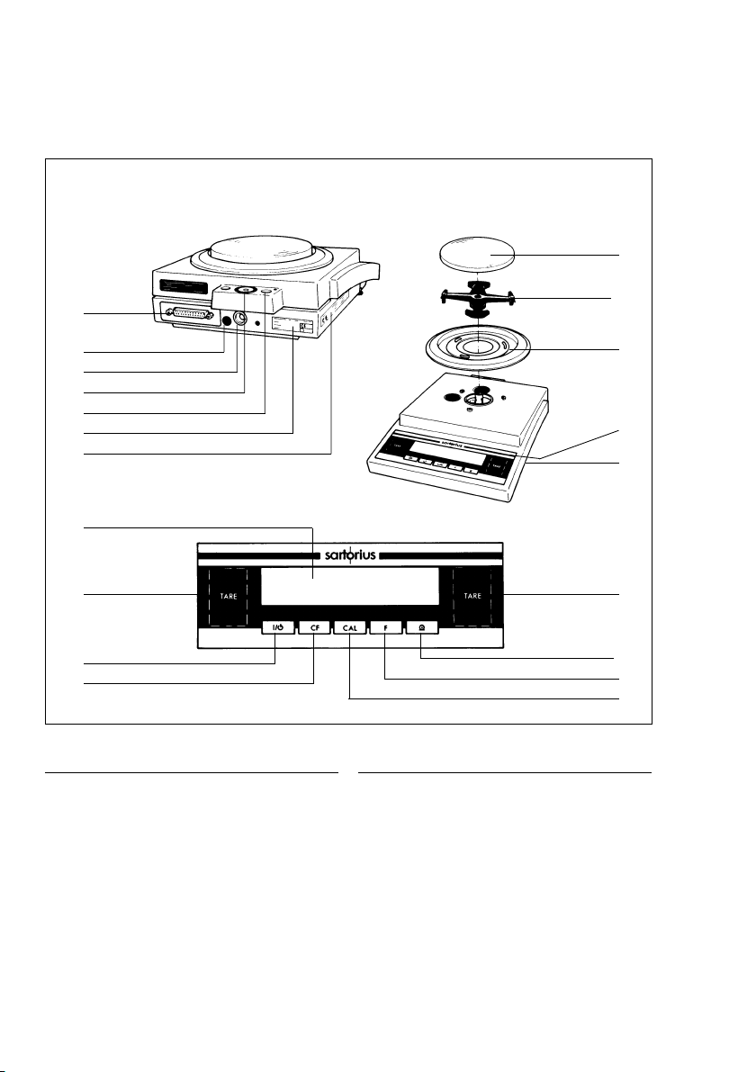
No. Designation Order no. for
replacement
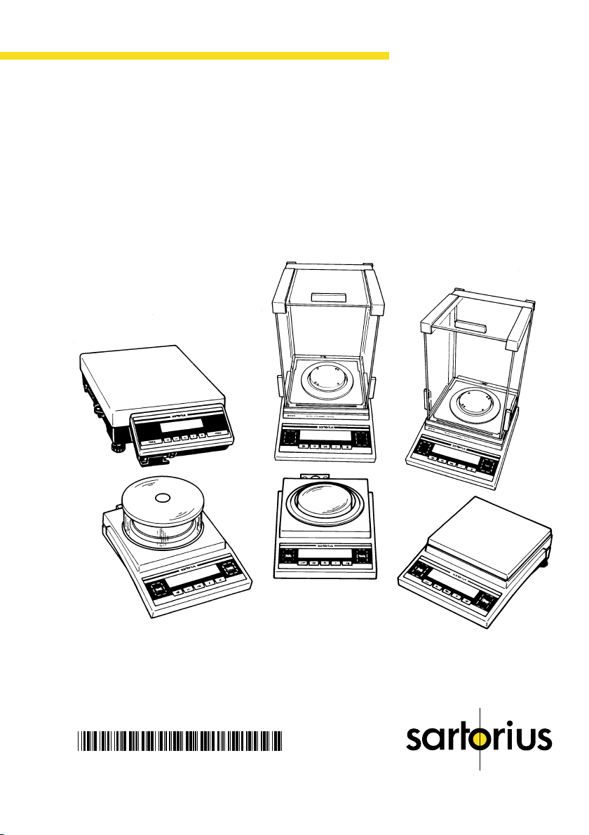
1 Weighing pan 69 B20116
2 Shield disk 69 B20117
3 Metrological ID label
for verified balances approved
for use as legal measuring instruments
4 Menu access switch
5 Leveling foot 69 B20005
6 Zero-setting and tare keys t
7 Print key (data output) p
8 Function key v
9 Adjustment/calibration key q
10 CF key (clear function) c
11 On/off key e (standby)
No. Designation Order no. for
replacement
12 Weight display
13 DC jack
14 Verification ID label with metrological
data for verified balances approved
for use as legal measuring instruments
15 Manufacturer’s label with
the C mark of conformity
16 Data interface port
17 Level indicator
Not shown: Dust cover 69 60BP07
Caps and plugs (set) 69 B20009
BP 211D, BP 211D-0CE
12
6
11
10
6
8
9
7
17
16
15
14
13
2
1
4
3
5
Page 6
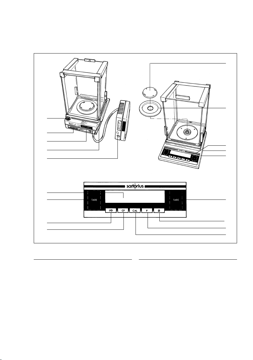
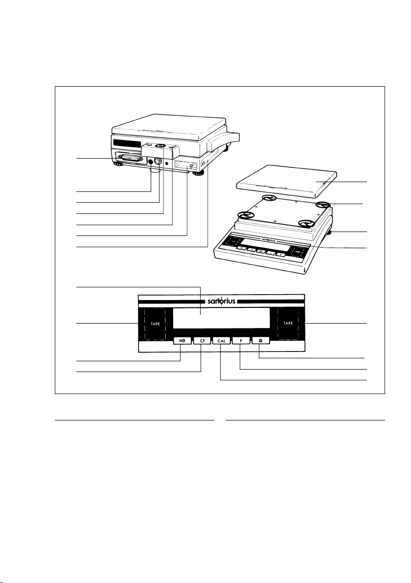
BP 301S,BP 221S,BP161P, BP121S, BP 61S, BP 301S-0CE,
BP 221S-0CE, BP161P-0CE,BP121S-0CE,BP 61S-0CE
17
1
2
16
15
14
13
12
6
11
10
No. Designation Order no. for
replacement
1 Weighing pan 69 B20116
2 Shield ring 69 B20117
3 Metrological ID label
for verified balances approved
for use as legal measuring instruments
4 Menu access switch
5 Leveling foot 69 B20005
6 Zero-setting and tare keys t
7 Print key (data output) p
8 Function key v
9 Adjustment/calibration key q
10 CF key (clear function) c
11 On/off key e (standby)
3
4
5
6
7
8
9
No. Designation Order no. for
replacement
12 Weight display
13 Verification ID label with metrological
data for verified balances approved
for use as legal measuring instruments
14 DC jack
15 Manufacturer’s label with
the C mark of conformity
16 Data interface port
17 Level indicator
Not shown: Dust cover 69 60BP07
Caps and plugs (set) 69 B20009
6
Page 7
7
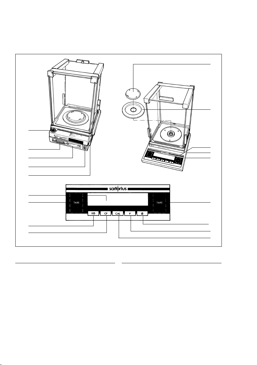
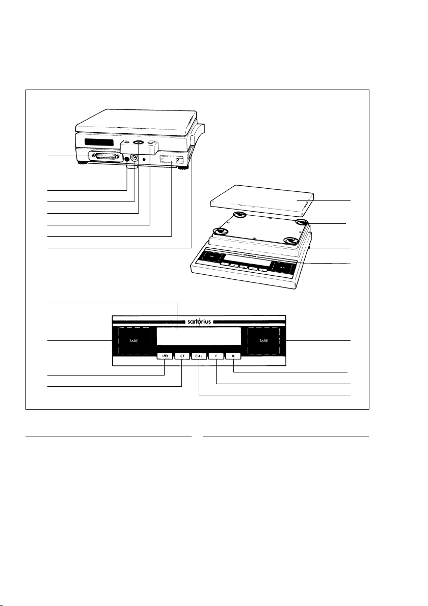
No. Designation Order no. for
replacement
1 Weighing pan 69 B20002
2 Shield ring 69 B20015
3 Metrological ID label
for verified balances approved
for use as legal measuring instruments
4 Menu access switch
5 Leveling foot 69 B20005
6 Zero-setting and tare keys t
7 Print key (data output) p
8 Function key v
9 Adjustment/calibration key q
10 CF key (clear function) c
11 On/off key e (standby)
12 Weight display
No. Designation Order no. for
replacement
13 Verification ID label with metrological
data for verified balances approved
for use as legal measuring instruments
14 DC jack
15 Manufacturer’s label with
the C mark of conformity
16 Data interface port
17 Level indicator
18 Lug for attaching an antitheft locking device
19 Draft shield cover 69 L22009
20 Glass draft shield cylinder 69 L22007
21 Pan support 69 B20011
Not shown: Caps and plugs (set) 69 B20009
BP 410 S,BP 310 S,BP 310 P,BP150,
BP 410 S-0CE,BP 310S-0CE, BP310 P-0CE, BP 150-0CE, BP 110-0CE
12
6
11
10
16
4
14
17
18
15
13
21
20
19
2
1
3
5
6
8
9
7
Page 8
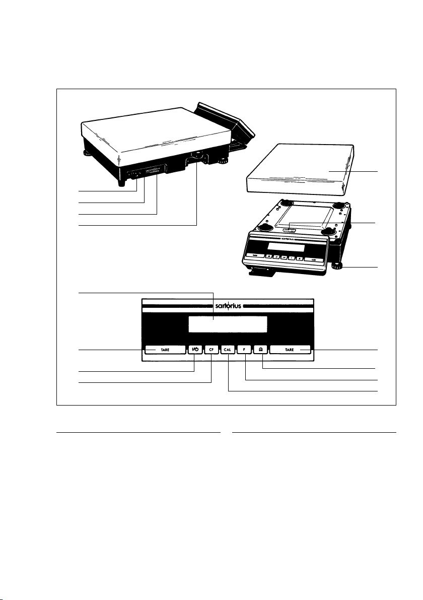
BP 610,BP410, BP 610-0CE
1
16
4
14
17
18
15
13
12
6
11
10
No. Designation Order no. for
replacement
1 Weighing pan 69 B20002
2 Shield ring 69 B20015
3 Metrological ID label
for verified balances approved
for use as legal measuring instruments
4 Menu access switch
5 Leveling foot 69 B20005
6 Zero-setting and tare keys t
7 Print key (data output) p
8 Function key v
9 Adjustment/calibration key q
10 CF key (clear function) c
11 On/off key e (standby)
12 Weight display
21
2
3
5
6
7
8
9
No. Designation Order no. for
replacement
13 Verification ID label with metrological
data for verified balances approved
for use as legal measuring instruments
14 DC jack
15 Manufacturer’s label with
the C mark of conformity
16 Data interface port
17 Level indicator
18 Lug for attaching an antitheft locking device
21 Pan support 69 B20011
Not shown: Caps and plugs (set) 69 B20009
8
Page 9
9
No. Designation Order no. for
replacement
1 Weighing pan 69 B20003
3 Metrological ID label
for verified balances approved
for use as legal measuring instruments
4 Menu access switch
5 Leveling foot 69 B20005
6 Zero-setting and tare keys t
7 Print key (data output) p
8 Function key v
9 Adjustment/calibration key q
10 CF key (clear function) c
11 On/off key e (standby)
12 Weight display
No. Designation Order no. for
replacement
13 Verification ID label with metrological
data for verified balances approved
for use as legal measuring instruments
14 DC jack
15 Manufacturer’s label with
the C mark of conformity
16 Data interface port
17 Level indicator
18 Lug for attaching an antitheft locking device
22 Shock absorber 69 B20006
Not shown: Caps and plugs (set) 69 B20009
BP 4100 S, BP 3100 S, BP 3100 P, BP2100 S,BP1200,BP 3100 S-0CE,
BP 4100 S-0CE, BP 3100 P-0CE, BP 2100 S-0CE,BP 2100-0CE, BP1200-0CE
12
6
11
10
16
4
14
17
18
15
13
1
5
22
3
6
8
9
7
Page 10
B P 810 0, B P 610 0, B P 410 0, B P 210 0, B P 8,
BP 8100-0CE, BP 6100-0CE, BP 8-0CE
16
4
14
17
18
15
13
12
6
11
10
No. Designation Order no. for
replacement
1 Weighing pan 69 B20004
3 Metrological ID label
for verified balances approved
for use as legal measuring instruments
4 Menu access switch
5 Leveling foot 69 B20005
6 Zero-setting and tare keys t
7 Print key (data output) p
8 Function key v
9 Adjustment/calibration key q
10 CF key (clear function) c
11 On/off key e (standby)
12 Weight display
1
22
5
3
6
7
8
9
No. Designation Order no. for
replacement
13 Verification ID label with metrological
data for verified balances approved
for use as legal measuring instruments
14 DC jack
15 Manufacturer’s label with
the C mark of conformity
16 Data interface port
17 Level indicator
18 Lug for attaching an antitheft locking device
22 Shock absorber 69 B20006
Not shown: Caps and plugs (set) 69 B20009
10
Page 11
11
No. Designation Order no. for
replacement
1 Weighing pan 69 LC0107
4 Menu access switch
5 Leveling foot 69 LC0092
6 Zero-setting and tare keys t
7 Print key (data output) p
8 Function key v
9 Adjustment/calibration key q
10 CF key (clear function) c
11 On/off key e (standby)
No. Designation Order no. for
replacement
12 Weight display
14 DC jack
15 Manufacturer’s label with
the C mark of conformity
16 Data interface port
17 Level indicator
Not shown:
Plug for menu access switch 69 I31113
BP16000 S, BP12000S,BP 34000P, BP34
12
6
11
10
14
4
16
17
1
5
15
6
8
9
7
Page 12

Please read through these installation and
operating instructions carefully before operating your
new balance.
Warranty
Do not miss out on the benefits of our full warranty.
Please complete the warranty registration card,
indicating the date of installation, and return the card
to your Sartorius office or dealer.
Storage and Shipping Conditions
Allowable storage temperature: +5°C …+40°C
+41°F…+104°F
In case there is any visible damage, proceed as
directed in the section entitled “Safety Inspection.”
Save the box and all parts of the packaging for any
future shipment of your balance as only the complete
original standard packaging ensures safe transport.
Before packing your balance, unplug all connected
cables to prevent damage.
Do not expose the balance unnecessarily to extreme
temperatures, moisture, shocks, blows or vibration.
12
Page 13
Installation Instructions
Ambient Conditions
When choosing a location to set up your balance,
observe the following:
– Set up the balance on a stable, even surface
(benchtop or floor), or place it on a wall console
(see “Accessories”)
– Avoid placing the balance in close proximity
to a heater or otherwise exposing the balance
to extreme heat or to direct sunlight
– Protect the balance from drafts that come
from open windows and doors
– Avoid exposing the balance to extreme vibrations
during weighing
– Protect the balance from aggressive
chemical vapors
– Do not operate the balance in a hazardous
area/location
Do not expose the balance to extreme moisture over
long periods. Moisture in the air can condense on
the surfaces of a cold balance whenever it is brought
to a substantially warmer place. If you transfer the
balance to a warmer area, make sure to condition it
for about 2 hours at room temperature, leaving it
unplugged from AC power. Afterwards, keep the
balance connected continuously to AC power.
13
Page 14

Using Verified Balances as Legal Measuring Instruments in the EU*
You must calibrate the balance at the place of installation before using it
as a legal measuring instrument (see the section entitled “Adjustment/
Calibration” starting on page 22).
This balance is not allowed to be used for weighing goods intended for direct
sale to the public. The type-approval certificate for verification applies only
to non-automatic weighing instruments. For balances of accuracy class k,
a thermometer and barometer are recommended for monitoring ambient
conditions. The temperature range indicated on the verification ID label must not
be exceeded during operation.
The balance must warm up for at least 24 hours after initial connection
to AC power.
* = including the Signatories of the Agreement on the European Economic Area
14
Page 15
Getting Started
– Remove the plastic wrapping, adhesive tape and styrofoam from the balance.
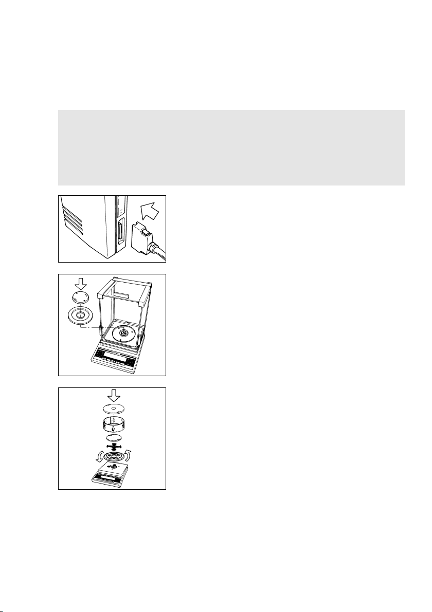
Connecting the BP 211 D (-0CE) Balance
to the Electronics Box:
– Plug the cable into the socket of the electronics box.
Preparing the Weighing Chamber for Balances
with an Analytical Draft Shield Chamber
Place the components listed below inside the chamber
in the order given:
– Shield ring (2)
– Weighing pan (1)
Preparing Balances with a Round Glass Draft Shield
– Place the shield disk (2) on the balance. Turn the disk
counterclockwise until it stops and is secured.
Place the components listed below on the balance
in the order given:
– Pan support (21)
– Weighing pan (1)
– Glass draft shield cylinder (20)
– Draft shield cover (19)
* = including the Signatories of the Agreement on the
European Economic Area
Control Seals on Verified Balances Approved for Use as Legal Measuring
Instruments in the EU*:
Legal regulations require the verified balance to be sealed. This control seal
consists of an adhesive label with the name “Sartorius” on it. This seal will
be irreparably damaged if you attempt to remove it. In this case, the validity of
the seal becomes void and you must have your balance re-verified.
15
Page 16
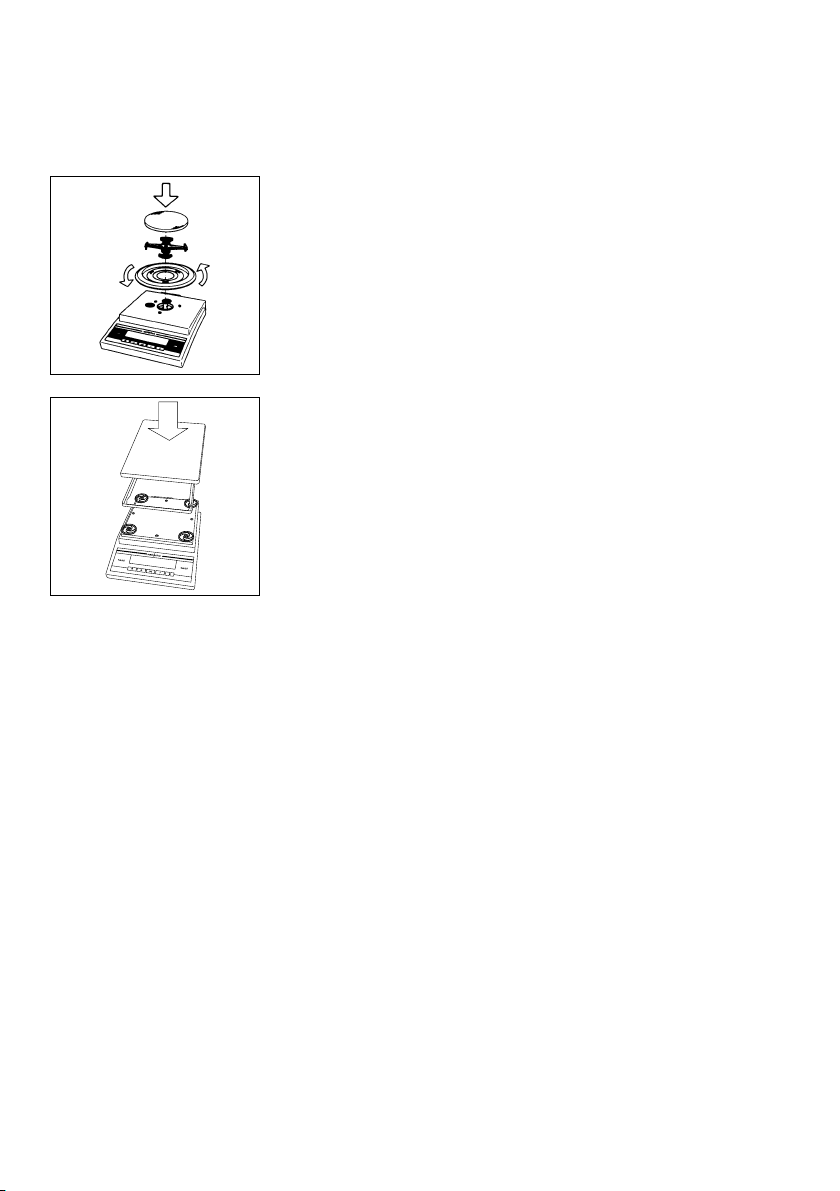
Preparing Balances with a Round Weighing Pan
– Place the shield disk (2) on the balance. Turn the disk
counterclockwise until it stops and is secured.
Place the components listed below on the balance
in the order given:
– Pan support (21)
– Weighing pan (1)
Preparing Balances with a Rectangular
Weighing Pan
Place the components listed below on the balance
in the order given:
– Pan shield (only for model BP4100 S-0CE or
the option YDS02BP)
– Weighing pan (1)
Connecting the Balance to AC Power
The balance is powered by an AC adapter. Make sure that the voltage rating
printed on this unit is identical to your local line voltage.
If the voltage specified on the label or the plug design of the AC adapter does
not match the rating or standard you use, please contact your dealer. The AC
adapters have IP 20 protection in accordance with DIN VDE 0470/EN 60529.
Important Note:
Use only original adapters. Use of AC adapters from other manufacturers, even if
these units have a registered approval rating from a national testing laboratory,
requires the consent of an authorized service technician. To operate the balance
using an external rechargeable battery pack or an industrial power supply (IP 65),
see “Accessories.”
16
Page 17
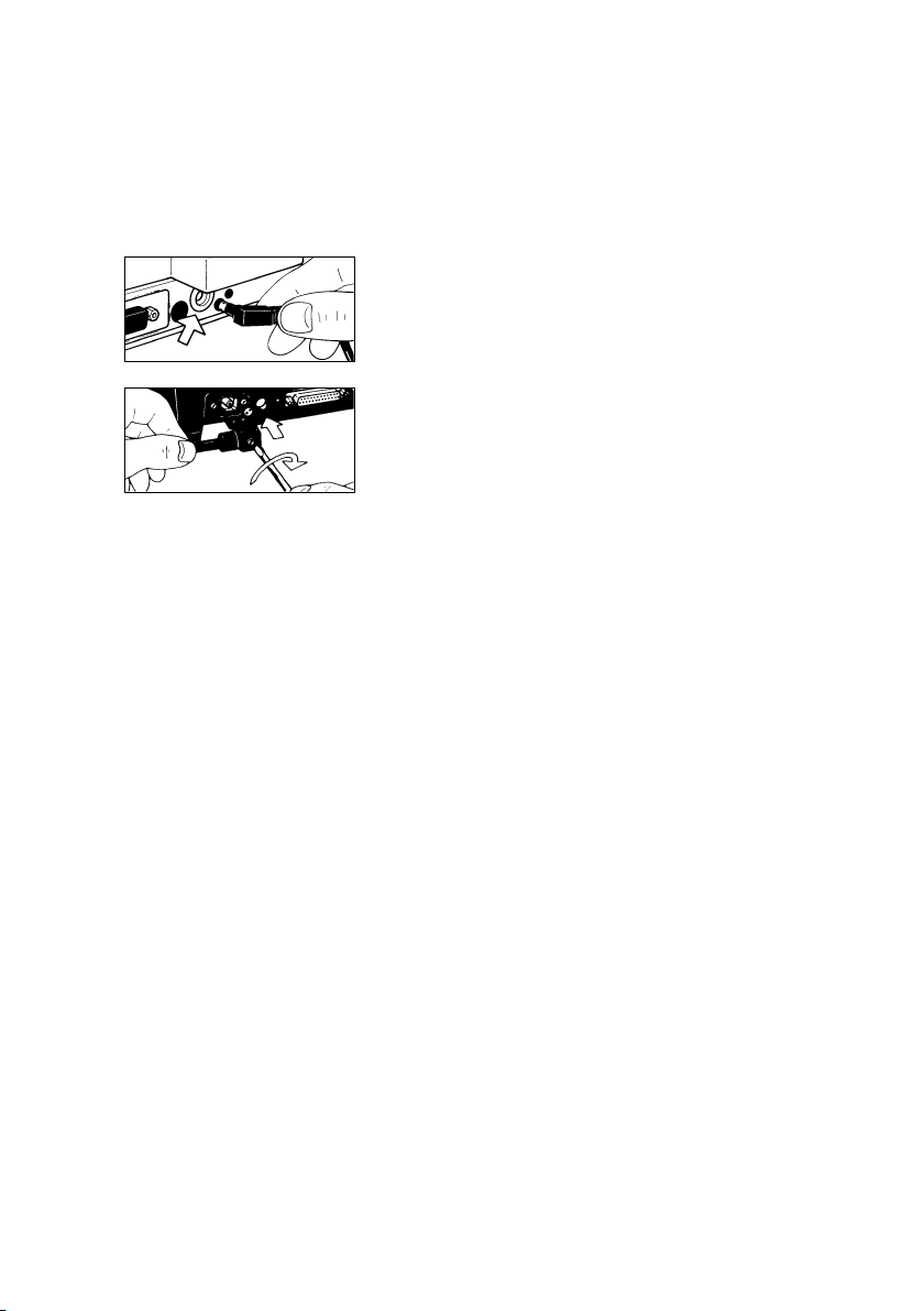
Plug the cord of the AC adapter into the balance
as follows:
– Use the DC jack (14) for balances with a weighing
capacity of <10 kg
– Use the DC jack (14) for balances with a weighing
capacity of ≥10 kg
Insert the right-angle plug into the jack as shown in the
diagram on the left; then tighten the screw.
Then insert the plug of the AC adapter into a wall outlet (mains).
Voltage Selection
(does not apply to balances with a weighing capacity of ≥12 kg)
You can select the voltage only if you use our portable power supply (6971172)
that has a European-type plug (rounded prongs).
Safety Precautions
The AC adapter rated to Class 2 can be plugged into any wall outlet without
requiring any additional safety precautions. The ground terminal is connected to
the balance housing, which can be additionally grounded for operation.
The data interface is also electrically connected to the balance housing (ground).
Information on Radio Frequency Interference
Note:
This equipment has been tested and found to comply with the limits for a Class A
digital device, pursuant to Part 15 of the FCC Rules. These limits are designed
to provide reasonable protection against harmful interference when the equipment
is operated in a commercial environment. This equipment generates, uses, and
can radiate radio frequency energy and, if not installed and used in accordance
with the instruction manual, may cause harmful interference to radio
communications. Operation of this equipment in a residential area is likely to
cause harmful interference, in which case the user will be required to correct the
interference at his own expense. Changes or modifications not expressly
approved by Sartorius AG could void the user’s authority to operate the equipment.
17
Page 18
Connecting Electronic Peripheral Devices
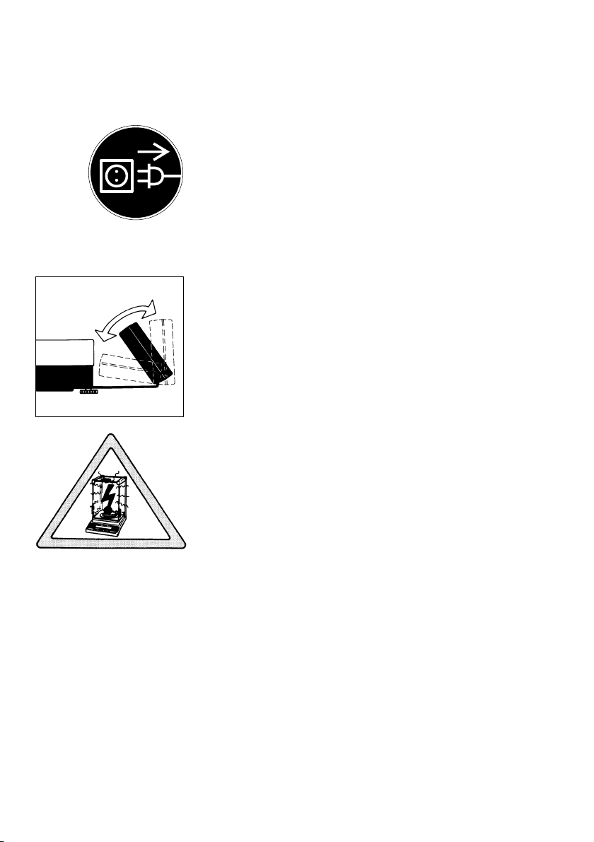
Make absolutely sure to unplug the balance from AC
power before you connect or disconnect a peripheral
device (printer or PC) to or from the interface port.
Adjusting the Display Unit on Balances with
a Weighing Capacity of ≥10 k g
Adjust the display unit to the position desired.
Information on Weighing Electrostatically Charged Samples
If static electricity from the sample or container
is interfering with the weighing procedure (causing
unstable readouts), use an antistatic pan instead of the
standard weighing pan when weighing on balances
with a readability of 0.1 mg (see “Accessories”).
18
Page 19

Leveling the Balance Using the Level Indicator
At the place of installation, level the balance using
the leveling feet (5) so that the air bubble is centered
within the circle of the level indicator (17).
For balances with a rectangular pan and a weighing
capacity of <10 kg:
Retract the two auxiliary feet located at the back
of the balance.
Use the level indicator as a guide to level the balance
as follows:
To lift the balance, extend the front leveling feet
(turn clockwise).
To lower the balance, retract the front leveling feet
(turn counterclockwise).
For balances with a rectangular pan and a weighing
capacity of <10 kg:
After rectracting the rear auxiliary feet, extend them
until they touch the surface on which the balance rests.
19
Page 20
Operating the Balance
Warmup Time
To deliver exact results, the balance must warm up for at least 30 minutes after
connection to AC power or after a power outage. Only after this time will the
balance have reached the required operating temperature.
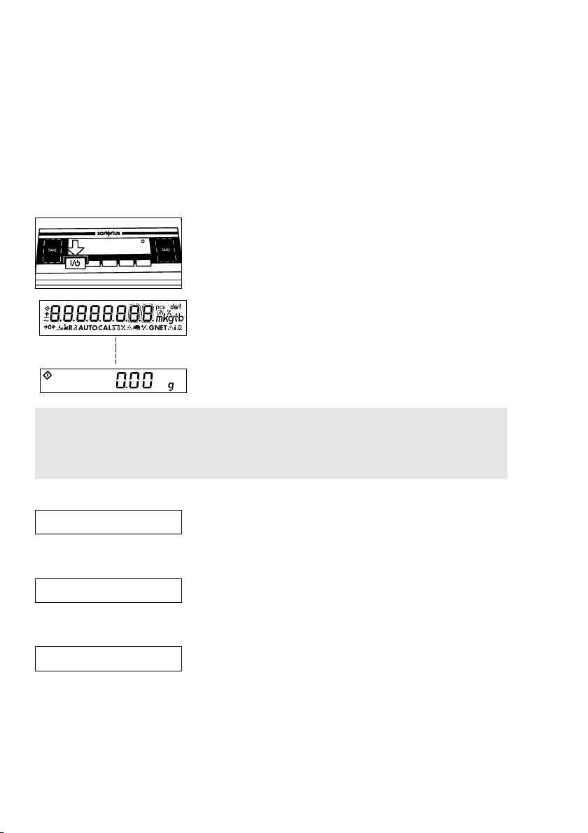
Turning the Display On and Off (Standby Mode)
Press the e key (11) to turn the display on and off.
Self-Test
After the balance has been turned on, an automatic
self-test of the balance’s electronic circuitry is
▼
Important Note Concerning Verified Balances Approved for Use as Legal
Measuring Instruments in the EU*:
The last digit on the display is bordered when the verification scale interval “e”
is greater than the scale interval “d.”
performed. At the end of the self-test, a zero readout
is displayed. This means that the balance is ready
to operate.
The display shows the following special codes for your information:
o
O displayed in the upper right corner stands for OFF
The balance was disconnected from AC power
(balance reconnected to AC power or power outage
longer than 3 seconds).
o
O displayed in the lower left corner means standby
The display has been turned off by the e key (11).
The balance is now in the ready-to-operate mode and
does not require warmup.
b
b means busy
Once you have turned on the balance, the b symbol
will be displayed until you press a key. During
operation, this symbol indicates that the balance
processor is still busy processing a function and will not
accept another command to perform any other
functions at this time.
* = including the Signatories of the Agreement on the European Economic Area
20
Page 21
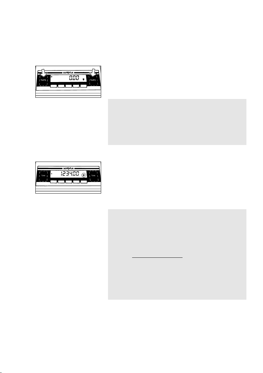
Taring
A weight can be determined accurately only from
a defined zero point. Press one of the t keys (6)
to zero the weight display. You can tare within the
entire weighing range of the balance.
Simple Weighing (Weight Determination)
Place your sample on the weighing pan (1) to
determine the weight. Read off the weight indicated
on the display only after the weight unit “g”
or a different unit selected appears as the stability
symbol. You can find more information on the weight
units on page 33 under “Weight Units.”
* = including the Signatories of the Agreement on the
European Economic Area
Important Note Concerning Verified Balances
of Accuracy Class k
To avoid measuring errors, the respective air density
must be allowed for. The following formula is used to
calculate the mass of the sample:
1– ρL/8000 kg m
–3
m = n
w
1– ρL/ρ
m = mass of the sample
nw= weight readout
ρ
L
= air density during weighing
ρ = density of the sample
Important Note Concerning Verified Balances
Approved for Use as Legal Measuring Instruments
in the EU*:
The symbol n in the weight display (on the left)
shows that the balance is exactly tared to “Zero”
(±0.25 of a scale interval).
21
Page 22
Calibration/Adjustment
During calibration1), the span of the balance is adjusted to the changes in
ambient conditions.
You must adjust or calibrate your new balance at the place of installation after
each warmup period and before the first measurement. You must also re-adjust
or recalibrate your balance each time you set it up in a different area or when
ambient conditions change (especially the temperature). Verified balances
approved for use as legal measuring instruments must be adjusted/calibrated
at least once a day.
The balance offers you various adjustment and calibration functions. You can
select these functions by setting the appropriate menu codes. For more information,
refer to “Balance Operating Menu.”
You can interrupt any adjustment or calibration function by pressing c (10).
Using Verified Balances as Legal Measuring Instruments in the EU*:
Before using your balance as a legal measuring instrument, you must carry
out an “Internal Calibration” operation at the place of installation after the
warmup period.
Internal Calibration for Balances with a Built-in
Calibration Weight
22
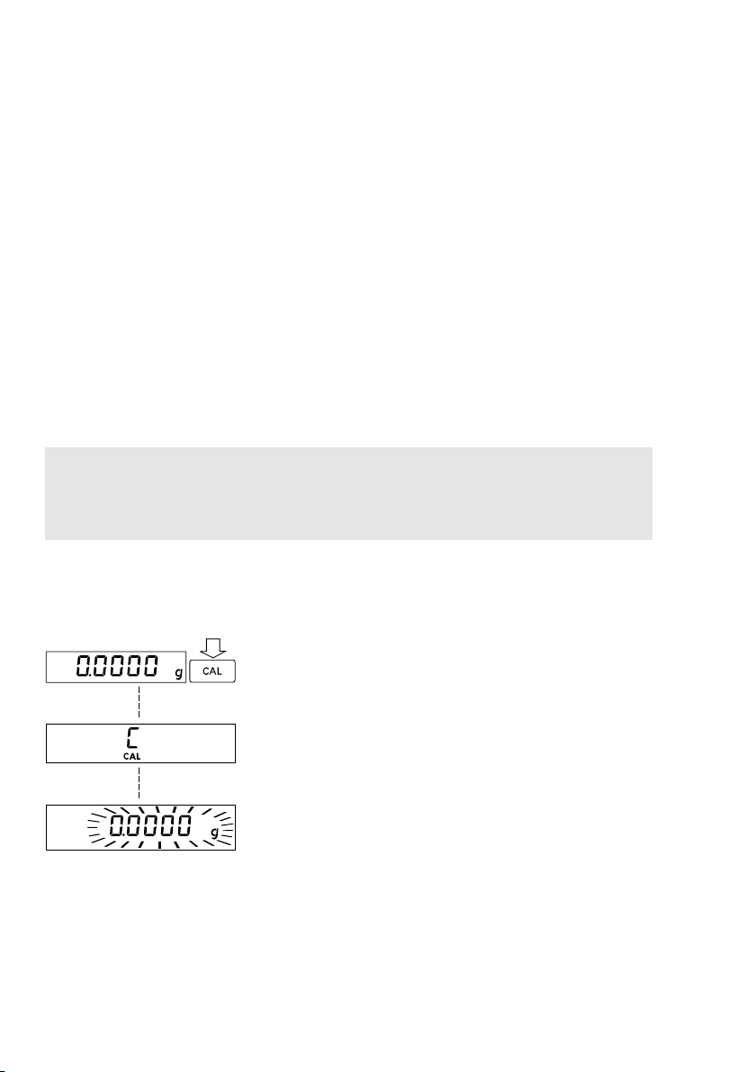
Menu code selection: 1 9 3**
When the display shows a zero readout, press the
q key (9) to activate the calibration function.
▼
1
) “Calibration” technically means to determine
the difference between the balance readout and
the actual weight on the pan to determine the
▼
accuracy. Adjustment means to bring a balance
into the state of accuracy required for its use.
Therefore, “calibration,” as used in this manual,
actually means “adjustment.”
** = including the Signatories of the Agreement on
the European Economic Area
** = factory setting for standard balances with
a readability of ≤ 0.1mg and for verified
balances approved for use as legal measuring
instruments in Europe.
Page 23
The built-in calibration weight is internally applied
by servomotor and removed at the end of adjustment
or calibration.
If any interference affects the calibration procedure,
you may obtain a brief display of the error code
“Err 02.”
In this case, tare and press the q key again.
Important Note
! During calibration, the weighing pan must
be unloaded.
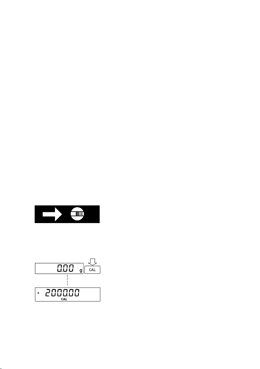
External Calibration**
Menu code selection – for standard balances: 1 9 1*
– for verified balances: 1 9 7
Use only calibration weights with nominal mass values
and tolerances equal to or better than the accuracy
class specified for your balance. You can find
an overview of the calibration weight sets under
“Accessories.”
Unlocking the Access Switch on Verified Balances
of Accuracy Class k:
– Remove the protective cap from the menu
access switch (4) on the rear panel of the computing
device.
– Move the menu access switch (4) in the direction
of the arrow.
When a zero readout is displayed, press the q
key (9). This starts calibration. The calibration weight
in grams is then displayed.
Errors or interference at the start of the calibration
routine are indicated by the error code “Err 02.” If this
is the case, tare and press the q key again when
a zero readout appears.
** = factory setting on standard balances with
a readability of ≥1mg
** = not applicable to verified precision balances
of accuracy class K
23
▼
Page 24
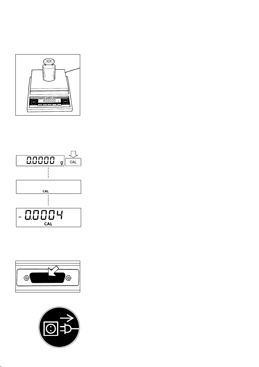
Center the calibration weight on the weighing pan.
The balance then calibrates automatically.
At the end of calibration, the calibration weight
readout and the stability symbol “g” are displayed.
Calibration Test for Balances with a Built-in
Calibration Weight
Menu code selection: 1 9 4
When a zero readout is displayed, press the
q key (9). The built-in calibration weight is now
internally applied by servomotor. At the same
▼
time, CAL is displayed. After the display has
stabilized, the deviation of the current readout from the
target weight (in grams only) is indicated.
If external interference affects the calibration test, you
▼
may obtain a brief display of the error code “Err 02.”
In this case, tare; then press the q key again.
Blocking the Calibration/Adjustment Functions
You can block these functions by setting code 1 9 7
(when the menu access switch (4) is locked).
24
Interface Port
Depending on the balance model, unfasten or remove
the protective cap from the data interface port.
– Plug the connector into the interface port
– Secure the connector by tightening the screws
To print or output data, press the p key (7).
Important Note
Make absolutely sure to unplug the balance from AC
power before you connect or disconnect a peripheral
device (printer or PC) to or from the interface port.
For information about the data output parameters
and data ID codes, see page 36.
Page 25
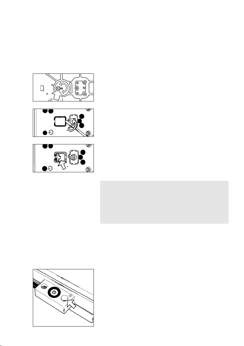
Below-Balance Weighing
A port for a below-balance weighing hanger is located
on the bottom of the balance (for balances with
a weighing capacity of ≥10 kg, see “Accessories”).
For Balances with an Analytical Draft
Shield Chamber:
To hook a sample on the hanger, open the belowbalance port by turning the cover plate.
For Precision Balances (Weighing Capacity
of <10 kg):
To open the below-balance port, remove the cover
plate from the bottom of the balance.
Now you can attach a sample using a suspension
wire, for example. Common applications for belowbalance weighing include density determination
and immersing a sample in a special atmosphere
(medium for reaction).
Important Note
When you use the below-balance weighing hanger,
you must install a shield for protection against drafts.
Fastening an Antitheft Locking Device**
To fasten an antitheft locking device, use the lug (18)
located on the rear panel of the balance.
** = including the Signatories of the Agreement on the
European Economic Area
** = not on BP 211 D, BP 301S, BP 221S,
BP 161 P, BP 121 S, BP 61S (-0CE), BP 16000 S,
BP 12000 S, BP 34000 P, BP 34
Important Note Concerning Verified Balances
Approved for Use as Legal Measuring Instruments
in the EU*:
The below-balance weighing port may not
be opened or used when an approved balance is
being operated as a legal measuring instrument.
25
Page 26

Troubleshooting Guide
Problem Causes Solution
No segments – No AC power – Check the AC power
appear on the is available supply
weight display (13) – The AC adapter is not – Plug in the AC adapter
plugged in
No segments – The surface on which the – Make sure that the ambient
appear on the weight balance rests is not stable conditions are stable
display after – The balance has not – Prevent vibrations from
calibration/adjustment yet internally stabilized affecting the surface on
which the balance rests
– Close the draft shield
The weight display – The load exceeds the – Unload the balance
shows “H” capacity of the balance
The weight display – The weighing pan (1) – Position the pan
shows “L” is not in place
or “Err 54”
“Err 235”on the – Cable not connected – Plug in the cable correctly
BP 211 D (-0CE) properly
– Electronics box taken from – Make sure components are
another balance model appropriately connected
The weight readout – Too much vibration, – Access the menu to select
changes constantly or the balance is the correct code for
exposed to a draft the weighing environment
– The draft shield is – Close the draft shield
not completely closed
– A foreign object is – Remove the foreign object
caught between the pan
and the balance housing
– The below-balance – Close the port for below-
weighing port is open balance weighing
– The sample does not have
a stable weight (absorbs
moisture or evaporates)
– The sample is
electrostically charged
The weight readout – The balance has – Calibrate the balance
is obviously wrong not been calibrated (see page 22)
– The balance was not – Tare before weighing
tared before weighing
26
Page 27

Care and Maintenance
Servicing
Regular servicing of your balance by a Sartorius
technician will ensure its continued weighing
accuracy. Sartorius can offer you service contracts
with your choice of regular maintenance intervals
ranging from1month to 2 years.
Cleaning
Before cleaning the balance, unplug the AC adapter
from the wall outlet (mains supply).
Please do not use any aggressive cleaning agents
(solvents or similar agents). Instead, use a piece of
cloth which has been wet with a mild detergent (soap).
Make sure that no liquid enters the balance housing.
After cleaning, wipe down the balance with a soft,
dry piece of cloth.
Carefully remove any sample residue/spilled powder
by using a brush or a hand-held vacuum cleaner.
Make sure that no liquid or dust enters the crevice
surrounding the pan adapter.
Safety Inspection
If there is any indication that safe operation of the
balance with the AC adapter is no longer warranted,
turn off the power and disconnect the equipment
from AC power immediately. Lock the equipment in
a secure place to ensure that it cannot be used for the
time being.
Safe operation of the balance with the AC adapter
is no longer ensured when
– there is visible damage to the AC adapter
– the AC adapter no longer functions properly
– the AC adapter has been stored for a relatively long
period under unfavorable conditions
In this case, notify your nearest Sartorius Service
Center Unit. Only service technicians who are
authorized by Sartorius and who have access to the
required maintenance manuals are allowed to perform
maintenance and repairwork on the equipment.
27
Page 28

Balance Operating Menu
In the operating menu, you can define how your
balance will adapt to ambient conditions and also
how it will work to meet your special requirements.
Changing Menu Code Settings
To select specific functions, you will need to set the
respective menu codes.
The keys have special functions for setting
menu codes:
q (9) = Increases a number by one with each
press (the numbers change in cycles)
t (6) = Confirms and stores a code setting; and
exits the menu
p (7) = Moves to the next of the three numbers
of a code (1st-2nd-3rd-1st, etc.)
The code for “automatic power-on” is 8 5 4.
28
Page 29

Accessing the Menu (Example: Code 8 5 4)
– Press e to turn off the balance.
– Turn the balance back on. While all segments are
displayed, briefly hold down t.
– For standard balances, if “-” is displayed next
to the left-hand number, proceed as follows to unlock
the menu:
– For balances with a weighing capacity of <10 kg,
remove the protective cap and move the menu
access switch (4)
in the direction of the arrow.
– For balances with a weighing capacity of ≥10 kg,
remove the larger-threaded cap located on the right
next to the DC jack and move the menu access
switch (4) in the direction of the arrows.
– Press q several times until “8” appears.
– Press p until the 2nd number of the code appears.
– Press q until “5” appears.
– Press p until the 3rd number appears (when
you move to the third number, the previously set
menu code will appear).
– Press q to select “4.”
– Confirming a Menu Code Setting
Press a t key to confirm the code you have just set
(this is indicated by the “o” after the code).
– To store the new menu code setting, press one
of the t keys for more than 2 seconds!
29
▼
▼
▼
▼
▼
▼
▼
▼
Page 30

The current code setting in the balance operating menu
is identified by a small, superscript “
o
” after the last
number. When you access the operating menu, the
previously set code will be displayed after you have
selected the right-hand number, which means the entire
menu code setting will be displayed. This makes it
easy for you to check the previously set menu codes.
If you would like to change several menu code
settings, you do not have to press a t key after each
change to exit the balance operating menu.
You can also confirm individual settings.
Important Note Concerning Standard Balances:
Please do not forget to relock the balance operating
menu to avoid inadvertent changes to the settings.
The symbol “–” indicates that the menu is locked.
Important Note Concerning Verified Balances
Approved for Use as Legal Measuring Instruments
in the EU*:
The balance operating menu on verified balances
cannot be locked with the menu access switch
(“–” not displayed).
Exiting the Menu without Storing Code Changes
Changes to the code settings are not stored if you turn
off the balance by pressing e while selecting the
code numbers or before pressing t to save a setting.
Undoing All Menu Code Changes – Reset Function
The reset function lets you undo all menu code
changes, which means that you will obtain the original
factory-set menu codes identified by an “*.” To use
this function, select code 9 – – 1o. See the previous
page for information on confirming and storing
a menu code setting.
30
Reset function Code
On 9 – – 1
Off 9 – – 2
* including the Signatories of the Agreement on the
European Economic Area
Page 31

Balance Operating Parameters
Adapting the Balance to Ambient Conditions
The balance can be adapted to the prevailing ambient conditions at the place
of installation.
Code
Very stable conditions 1 1 1*
Stable conditions 1 1 2*
Unstable conditions 1 1 3
Very unstable conditions 1 1 4
Standard Weighing Mode – Manual Filling Mode
You can optimally adapt your balance to meet either of these requirements.
In the manual filling mode, the display compensates for fluctuations of the load on
the balance, giving you especially fast and stable readouts.
Code
Standard weighing mode 1 2 1*
Manual filling mode 1 2 2
Stability Range
The stability symbol will remain displayed in the case
of a weight variation +/– Code
0.25 digit 1 3 1
0.5 digit 1 3 2*
1 digit1) 133
2 digits1) 134*
4 digits1) 135
8 digits1)2) 136
* = factory setting; depends on the balance model in some cases
1
) = not applicable to the BP 8-0CE and BP 2100-0CE
2
) = not applicable to the verified balances approved for use as legal measuring
instruments in the EU
31
Page 32

Tare Parameter
You can define when the balance will perform the taring operation:
Code**
At any time 1 5 1
Not until the readout is stable 1 5 2*
Auto Zero Function
When this zero-tracking function is activated, any slight changes off the zero
readout are automatically tared.
Code
Auto Zero on 1 6 1*
Auto Zero off 1 6 2
Adjustment/Calibration and Linearization Functions Using CAL
Internal Linearization applicable only to the BP 211 D, 301S (-0CE)
Code
External calibration 1 9 1*/**
Internal calibration for balances with a built-in
automatic calibration function 1 9 3*
Calibration test for balances with a built-in
automatic calibration function 1 9 4
Internal linearization with automatic calibration 1 9 6
Adjustment/calibration functions blocked 1 9 7
Important Note Concerning Verified Balances Approved for Use as Legal
Measuring Instruments in the EU:
For verified balances of accuracy class K, the menu access switch is adjusted
to lock the “External Linearization” function after verification, and a control seal is
affixed to the balance to lock the menu access switch.
** = factory setting; depends on the balance model in some cases
** = setting not applicable to verified balances of accuracy class K
32
Page 33

Weighing Using Two Weighing Units
The v key (8) lets you toggle back and forth between two weight units.
The 2nd unit is identified by the display symbol “R1.”
Code
v key blocked 2 1 1*
Mass unit conversion by toggling 2 1 2
General View – Weight Units
Symbol/Conversion factor Code
1 g = 1st level 2nd level R1
Grams (o)** o 1. 1 7 1 3 1 1
Grams g 1. 1 7 2* 3 1 2*
Kilograms1) kg 0.001 1 7 3* 3 1 3*
Carats** ct 5. 1 7 4 3 1 4
Pounds** lb 0.0022046226 1 7 5 3 1 5
Ounces** oz 0.035273962 1 7 6 3 1 6
Troy ounces** ozt 0.032150747 1 7 7 3 1 7
Hong Kong taels** tl (thl)3) 0.02671725 1 7 8 3 1 8
Singapore taels** tl (ths)3) 0.02646063 1 7 9 3 1 9
Taiwanese taels** tl (tht)3) 0.02666666 1 7 10 3 1 10
Grains** GN 15.43235835 1 7 11 3 1 11
Pennyweights** dwt 0.643014931 1 7 12 3 1 12
Milligrams2) mg 1000. 1 7 13 3 1 13*
Parts per pound** o (/lb)3) 1.1287667712 1 7 14 3 1 14
Chinese taels** tl (thlc)3) 0.02645547175 1 7 15 3 1 15
Mommes** m (mom)3) 0.2667 1 7 16 3 1 16
Carats** k (K)3) 5. 1 717 3 117
Tola** t (tol)3) 0.0857333381 1 7 18 3 1 18
Baht** b (bat)3) 0.06578947436 1 7 19 3 1 19
Mesghal** m (MS)3) 0.217 1 7 20 3 1 20
** = factory setting; depends on the balance model in some cases
** = not applicable to verif. balances approved for use as legal meas. instruments
1
) = not applicable to verified balances of accuracy class k
2
) = not applicable to verified balances of accuracy class K
3
) = unit symbols output via the data interface
33
Page 34

Display Modes
You can select the display mode that best meets your individual accuracy
requirements (last numeral). The display increments possible are as follows:
1, 2, 5, 10, 20, 50, etc.
Starting with the basic increments of a weight unit, the display accuracy can
be reduced by as many as three levels so that you will obtain a faster readout with
a reduced display accuracy. The display accuracy is reduced proportionally to
the selected basic increment of a weight unit. To make this concept easier
to understand, the three levels are designated as “rounding factors” in the tables
summarizing the various menu code settings.
Code
Display mode 1st level 2nd level R1
Highest possible accuracy 1 8 1* 3 2 1*
Last numeral blanked when load changes1) 182 322
Rounding factor 2** 1 8 3 3 2 3
Rounding factor 5** 1 8 4 3 2 4
Rounding factor 10** (last numeral off) 1 8 5 3 2 5
** = factory setting
** = not applicable to verified balances approved for use as legal measuring
instruments in the EU
1
) = applicable only to verified balances approved for use as legal measuring
instruments in the EU
34
Page 35

Interface Parameter Settings
Baud Rate Code
150 baud 5 1 1
300 baud 5 1 2
600 baud 5 1 3
1,200 baud 5 1 4*
2,400 baud 5 1 5
4,800 baud 5 1 6
9,600 baud 5 1 7
19,200 baud 5 1 8
Parity Code
Mark 5 2 1
Space 5 2 2
Odd 5 2 3*
Even 5 2 4
Number of Stop Bits Code
1 stop bit 5 3 1*
2 stop bits 5 3 2
Handshake Mode Code
Software handshake 5 4 1
Hardware handshake with 2 characters after CTS 5 4 2*
Hardware handshake with 1 character after CTS 5 4 3
*= factory setting
35
Page 36

Utilities for Printouts or Data Transfer
Sartorius balances come standard with an interface. You can plug a Sartorius
printer or a computer into this interface port. In addition, you can choose to have
data output from your balance to this on-line device either automatically or by
pressing the p key.
The balance operating menu lets you define the various parameters for data output.
Information on the data formats and for interfacing a computer or a different
peripheral device are available on request.
Data Output Parameter
This parameter is coupled with the stability parameter
Print on request = data is output only when the p key is pressed or a software
command is received
Auto print = continuous, automatic data output
Code
Print on request regardless of stability 6 1 1
Print on request after stability, with storage of the function 6 1 2*
Print on request at stability, without storage of the function 6 1 3
Auto print regardless of stability 6 1 4
Auto print at stability 6 1 5
Auto Print
You can stop and start automatic data output (auto print function) by pressing
the p key.
Code
Start/stop auto print using the p key 6 2 1
Auto print not stoppable 6 2 2*
Data Output at Defined Intervals
The menu code for “2 display updates” must be set if you connect the remote
display to the balance.
Auto print interval Code
1 display update 6 3 1*
2 display updates 6 3 2
* = factory setting
36
Page 37

Automatic Taring after Data Output (Print on Request)
This convenient setting lets you checkweigh a series of samples or products
without having to unload the balance after each weighing operation.
– the sample remains on the pan after the weight readout has been printed
or transferred to an on-line computer
– the balance is tared automatically after the weight readout has been printed
or transferred to an on-line computer
– you simply load the next sample or part
Code
Data output without automatic taring 6 4 1*
Data output with automatic taring 6 4 2
Automatic Output of the Application Parameters
After completing an application started by pressing the v key, you can have the
application parameters and results printed out or transferred to an on-line computer.
Code
Off 711*
On 712
Data ID Codes
To help you identify weights, piece counts, percentages, etc., a code letter is
printed or displayed in front of these values. For example, an “N” printed
or displayed in front of a weight value identifies it as a net weight. If you set the
code for “without data ID code,” only net weights, results in percent and
counting results will be output. You will find the data ID codes for a particular
application program listed in the corresponding description.
The ID code increases the data output format for each weight readout
from 16 to 22 characters.
ID code for data output Code
Without 7 2 1*
With 7 2 2
* = factory setting
37
Page 38

Automatic Output of the Tare Memory Data
If you have selected the application program “tare memory” (2 1 6), you can have
your choice of values output by pressing the v key:
Code
Last net value (individual value N1) 7 3 1*
Tare memory data (total T1) 7 3 2
Additional Functions
Menu Access Switch Function on Standard Balances
You can define the function of the menu access switch by setting the code for the
balance operating menu to “accessible.” The balance operating menu will then be
accessible at all times, which means that you can change the menu codes at any
time regardless of the setting of the menu access switch.
Access to the balance operating menu Code
Accessible 8 1 1
Depends on the setting of the menu access switch 8 1 2*
Menu Access Switch Function on Verified Balances
The balance operating menu can also be changed when the balance is being
used as a legal measuring instrument. Codes that are not permitted for operation
of the balance as a legal measuring instrument are blocked and cannot be
selected. For balances of accuracy class K, the menu access switch is adjusted
to lock the “External Calibration” function after verification. To do this, the switch
must be moved to the left. A control seal is affixed to the balance to lock the
menu access switch. Unauthorized attempts to remove this seal will irreversibly
damage it. If you break the seal, the validity of the verification will become
void, and you must have your balance re-verified.
Blocking the Keys
You can block all keys on the balance (except for e).
Key functions Code
Accessible 8 3 1*
Blocked 8 3 2
* = factory setting
38
Page 39

Universal Switch for Remote Control
You can connect an external universal switch to the interface port of your balance
for remote control of the functions listed below.
Functions Code
Print p 841*
Tare t 842
Adjust/calibrate/linearize (using q) 843
v key 8 4 4
c key 8 4 5
Power-On Mode
Depending on your requirements, you can change the power-on mode
of your balance.
The factory setting is: (power) off –> on <–> standby.
In this default setting, when you press the e key (11) to turn off the display, the
balance will remain in the standby mode. This means that it will be ready
to operate without requiring any warmup when you turn the display back on.
In the setting “Toggle between on and standby,” the balance will automatically
turn on again after it has been temporarily disconnected from AC power
or a power failure has occurred.
In the setting “Automatic power-on,” the balance will automatically turn on again
after it has been temporarily disconnected from AC power, the e key has
been
pressed, or after a power failure has occurred. In this setting, you cannot
use the
e key to turn off the balance. If your balance is connected to a central
power supply that is switched off overnight, the balance will turn on automatically
the next day as soon as the power supply is switched on again.
Power-on mode Code
(Power) off –> on <–> standby 8 5 1*
On <–> standby 8 5 3
Automatic power-on 8 5 4
* = factory setting
39
Page 40

Application Programs
In addition to the functions implemented for weighing, Sartorius Basic
offer you a variety of application programs.
To select an application program or a specific function, set the appropriate
code in the menu. The procedure for setting menu codes is described in detail
starting on page 28.
Using Verified Balances as Legal Measuring Instruments in the EU*:
All application programs can be selected on balances used as legal measuring
instruments. Non-metric values are indicated as follows:
Percent = %; Piece count (counting) = pcs; Computed value = o
plus
balances
Tare Memory
Tare Memory Code 2 1 6
Symbol displayed when a value is stored: NET
Press the v key (8) to store the tare weight. The balance is now automatically
tared so you can weigh again starting with a zero readout.
Practical Example: Tare – Net – Gross Weights
Menu code settings used in the example:
Function Code
Tare memory 2 1 6
Automatic output
of all parameters 7 1 2
With data ID code 7 2 2
Print tare memory 7 3 2
As an alternative, you can select
this automatic output parameter:
Print net value 7 3 1**
** = including the Signatories of the Agreement on the European Economic Area
** = factory setting
40
Page 41

Application: Obtaining printouts of tare, net and gross weights or outputting these
data to a computer
Step/Key Readout Data Output/Printout
c, t
0.00 g
Place container on pan +
22.65 g
v
0.00 g
NET
T1 + 22.65 g
Fill container with sample;
press p +
250.24 g
NET
N1 + 250.24 g
c, p +
272.89 g
N + 272.89 g
The data ID codes mean:
T1 + 22.65 g tare weight stored in the memory (weight value)
N1 + 250.24 g net weight when tare weight is stored
N + 272.89 g gross weight = tare + net
Practical Example: Net Total
Menu code settings used in the example:
Function Code
Tare memory 2 1 6
Automatic data output 7 1 2
With data ID code 7 2 2
Printout of individual
components/tare weights 7 3 1*
* = factory setting
As an alternative, you can select
this output parameter:
Printout of the net total
weight/total tare weight 7 3 2
41
Page 42

Application: Simple compounding and formulating of several components
with additive storage, automatic taring and outputting of the
component weights
Step/Key Readout Data Output/Printout
Place container on pan +
c, t
Weigh in 1st component; +
s
tore: v
Weigh in 2nd component; +
s
tore: v
Weigh in and store additional
components: v
Finish weighing in
components; output
total weight: c, p +
The data ID codes mean:
N1 + 60.33 g component weight (net individual weight)
N + 272.89 g total components weighed in (net total weight)
22.65 g
0.00 g
4.61 g
0.00 g
NET
60.33 g
0.00 g
NET
xxx.xx g
NET
272.89 g
N1 + 4.61 g
N1 + 60.33 g
N1 + xxx.xx g
N + 272.89 g
Weighing in Percent
Weighing in Percent Code 2 1 5
Symbol displayed: %
This application program enables you to obtain weight readouts in percent which
are in proportion to a reference weight. The reference weight readout is stored
as a menu-defined percentage (factory setting: 100%). After treating the sample,
place it on the weighing pan and read off the weight in percent.
42
Page 43

Changing the Reference Percentage
You can change the reference percentage in cycles. Choose from the following
settings: 5, 10, 20, 50 and 100.
To activate the Hold down v (8) for more than 2 seconds until
change function: “rEF 100 %” appears on the display
To change the setting: Briefly press v
To store the percentage: Hold down v for more than 2 seconds to store
this value permanently (in the non-volatile memory)
after you turn off the power
This setting is not canceled by the reset code 9 – – 1°!
Storage Parameter for the Reference Weight/Value
The reference weight/value is stored… Code
with full accuracy according to the internal resolution 3 5 1*
according to the display accuracy 3 5 2
When you exit the reference storage mode, “Err 22” may briefly be displayed.
This means that the new reference value has been stored.
Toggling between the Readout in Percent (%) and Weight (g)
After placing the sample on the weighing pan, you can toggle between the
readout in percent and the respective weight readout in grams by pressing
the v key after you have stored the reference value. To clear the readout in
percent, use the c key.
Display Parameter for Readouts in Percent
The following display parameters can be set for readouts in percent:
The readout in percent is displayed… Code
without a decimal place 3 6 1
with one decimal place 3 6 2*
with two decimal places 3 6 3*
with three decimal places 3 6 4
If the weight stored is too light to be displayed, the number of decimal places
is automatically decreased.
* = factory setting; depends on the balance model in some cases
43
Page 44

Practical Example: Determination of the Residual Weight in Percent
Menu code settings used in the example:
Function Code
Weighing in percent 2 1 5
Ref. % and weight 7 1 2
With data ID code 7 2 2
Application: Quick determination of the dry weight of a sample
Step/Key Readout Data Output/Printout
Place container on pan +
c, t
Add prepared sample +
to container; v +
For moisture analysis,
press t at this point
Remove container; dry sample
Reweigh sample in container +
p +
Press c to clear
residual weight readout and
reference value +
p +
The data ID codes mean:
pRef + 100 % reference percentage
Wxx% + 4.61 g net reference weight xx%
Prc + 72.5 % calculated percentage
N + 3.34 g net residual weight
22.65 g
0.00 g
4.61 g
100.0 %
0.0 %
xx.x %
72.5 %
72.5 %
3.34 g
3.34 g
nRef + 100 %
Wxx% + 4.61 g
Prc + 72.5 %
N + 3.34 g
44
Page 45

Counting
Counting Code 2 1 4
Symbol displayed: P
The counting program allows automatic conversion of weights into piece counts
based on a reference sample weight. A weight readout is stored as a reference
sample quantity (factory setting: 10 pcs = pieces). When you turn on the balance,
the reference sample quantity will be displayed as “rEF 10 pcs” before you enter
the piece count.
Displaying the Reference Sample Quantity
You can have the reference sample quantity (pcs) setting displayed by pressing
the v key when the balance is unloaded.
Changing the Reference Sample Quantity
You can change the reference sample quantity in cycles. Choose from the
following settings: 5,10, 20, 50 and 100.
To activate the Hold down v (8) for more than 2 seconds until
change function: “rEF…pcs” appears on the display
To change the setting: Briefly press v
To store the quantity: Hold down v for more than 2 seconds to store
this quantity permanently (in the non-volatile memory)
after you turn off the power
This setting is not canceled by the reset code 9 – – 1°!
Storage Parameter for the Reference Sample Weight
The reference weight is stored… Code
with full accuracy according to the internal resolution 3 5 1*
according to the display accuracy 3 5 2
When you exit the reference storage mode, “Err 22” may briefly be displayed.
This means that the new reference value has been stored.
Toggling between the Piece Count (pcs) and Weight (g)
After placing the sample on the weighing pan, you can toggle between the piece
count and the respective weight readout by pressing the v key.
*= factory setting
45
Page 46

Practical Example: Counting Small Parts
Menu code settings used in the example:
Function Code
Counting 2 1 4
Ref. qty. and ref. weight 7 1 2
With data ID code 7 2 2
Application: Counting bulk quantities of items with the same weight
Step/Key Readout Data Output/Printout
Place container on pan +
c, t
Add 10 counted parts
Press v to confirm reference rEF
sample quantity +
Fill container with desired
quantity of parts
(without counting them) +
p +
Press c to clear the
weight readout and
the reference value +
p +
The data ID codes mean:
nRef + 10 pcs reference sample quantity (piece count)
wRef + 5.6546 g reference weight
Qnt + 500 pcs calculated piece count
N + 2827.35 g net weight
22.65 gcs
0.00 gcs
5.6546 gcs
+
2827.35 gcs
2827.35 gcs
10 pcs
10 pcs
500 pcs
500 pcs
nRef + 10 pcs
wRef + 5.6546 g
Qnt + 500 pcs
N + 2827.35 g
46
Page 47

Animal Weighing/Averaging
Animal Weighing/Averaging Code 2 1 7
Symbol displayed: m
Use this program to determine the weights of live animals or weights under
unstable ambient conditions. In this program, the balance calculates the weight as
the average of a selectable number of individual weighing operations.
During averaging, the number of remaining individual subweighing operations
is shown on the application display in a “countdown” mode.
Once all subweighing operations have been performed, the calculated mean
value is indicated as a stable readout on the weight display.
Manual or Automatic Start Mode
Depending on the menu code you select, animal weighing will be started
automatically or manually by pressing a key.
If you select the “automatic mode,” you will have to press v to start the program
for averaging the first weight. You can press c to interrupt a weight
measurement in progress at any time. In the “automatic mode,” the symbol
“AUTO” will be displayed during weight measurement. The result is locked into
the display. The ”m” symbol or “AUTO” flashes during this time. The readout will
stop flashing after you have unloaded the balance, and the next weight will
be displayed.
Animal weighing/averaging will start by Code
Manual mode 3 8 1
Automatic mode 3 8 2*
Once averaging has been completed, the program will stop until the balance is
unloaded to half the value (50 display increments) of the storage threshold.
* = factory setting
47
Page 48

Delayed Start Mode
A rule of thumb to go by for selecting the right setting to weigh animals is:
the more active an animal is, the greater the difference must be between two
successive subweights measured.
Depending on individual requirements, starting the averaging operation can be
delayed either in the automatic or manual mode until the animal you are weighing
has calmed down to a certain degree.
In this case, the start criterion is defined by the difference between two successive
subweights measured. If the animal moves, the start criterion is not met; therefore,
averaging will not start. Once the animal has calmed down, the program
checks whether two measured subweights are within the previously selected range.
If so, the actual averaging operation will be started.
Delay start until… Code
difference is slight 3 7 1
difference is average 3 7 2*
difference is considerable 3 7 3
During averaging, the number of subweighing operations left to perform is shown
on the weight display (countdown mode).
Changing the Number of Subweighing Operations
You can change the number of subweighing operations used to average
a weight. Change this number in cycles. You can choose from the following
settings: 5,10, 20, 50 and 100.
To activate the Hold down v (8) for more than 2 seconds until
change function: “rEF 10” appears on the display
To change the setting: Briefly press v
If you enter a wrong number, press c to clear it
To store the number: Hold down v for more than 2 seconds to store
this number permanently (in the non-volatile memory)
after you turn off the power
This setting is not canceled by the reset code 9 – – 1°!
* = factory setting
48
Page 49

Storage Threshold for the Automatic Start Mode
To obtain an added measure of reliability in the automatic mode, in order to
avoid an “incorrect start,” a weight value must correspond to a minimum load
of 100 display increments.
Practical Example: Animal Weighing in the Automatic Start Mode
Menu code settings used in the example:
Function Code
Animal weighing 2 1 7
Delay start until dif. is average 3 7 2*
Automatic start mode 3 8 2*
Automatic output
of all parameters 7 1 2
With data ID code 7 2 2
Application: Automatic weighing of animals based on10 subweighing operations
Step/Key Readout Data Output/Printout
Place animal weighing bowl
on balance
c, t
0.00 g
Place 1st animal in bowl
v
10 g
mdef + 10
465.20 g
x-Net + 465.20 g
Remove 1st animal
Place 2nd animal in bowl
10 g
mdef + 10
388.53 g
x-Net + 388.53 g
Repeat above steps
for all animals
The data ID codes mean:
mdef + 10 defined number of subweighing operations
x-Net + 401.18 g calculated average
* = factory setting
As an alternative, you can select
this output parameter:
Other delay start 3 7 x
Manual start mode 3 8 1
49
Page 50

ISO/GLP-compliant Printout or Record
Application:
Use of the balance as a test and measuring instrument in quality assurance
systems in compliance with the requirements of ISO, GLP, GMP and EN (European
Standards) in which proof of the balance’s accurate performance is required.
The balance can record all completed calibration or adjustment operations and
print out data in compliance with the requirements of Good Laboratory
Practice (GLP). The balance, interfaced with a data printer or a computer, creates
a document that records the date, time, serial number and model number,
making it possible to clearly trace data to the balance that generated it and the
time at which it was generated.
Select the ISO/GLP-compliant printout or record mode by setting the respective
code in the balance operating menu:
ISO/GLP-compliant printout/record mode Code
Off 8 10 1*
Only for adjustment/calibration and linearization functions 8 10 2
Always on (e.g., for adjustment/calibration and linearization
functions, application programs, weight readouts) 8 10 3
The following menu code setting must be selected in order to obtain an ISO/GLPcompliant printout/record:
With data ID code 7 2 2
Important Note
!
Operating the Balance with a Device That Has an ISO/GLP Printing
or Recording Capability
You can connect a special Sartorius Data Printer to Basic
ISO/GLP-compliant printouts
To generate ISO/GLP-compliant records with a computer, you will need
special software. For information on writing this software, please ask Sartorius for
a detailed description.
* = factory setting
50
ISO/GLP-compliant printouts/records will not be generated if the
factory setting, code 7 2 1, is selected. In addition, do not select the
“Auto print” data output parameter (code 6 14 or 6 15).
plus
balances for generating
(order no. YDP03-0CE).
Page 51

Printout/Record for Adjustment or Calibration and Linearization Functions
A printout or record is generated at the end of the following functions:
– all calibration, adjustment and linearization procedures
– calibration test
The printout can have the following lines:
-------------------MC1 - Sartorius : Balance family and manufacturer
Model BP211D : Balance model
S/N 040500048 : Serial number of the balance
ID : Space for entering the workstation or operator ID
-------------------Date : 21-Mar-97 : Current date
Start: 10:05:30 : Time at which the application started
Cal. : Extern : Calibration mode (in this case,
“external calibration”)
Set. : 200.00000 g : Calibration weight value
(only for “external calibration”)
End : 10:05:45 : End of application
Name : : Space for signature of the operator responsible
--------------------
Additional information for other calibration modes:
Cal. : Intern : Internal calibration
Stat.: Complete : Status comment for calibration or linearization
functions
Cal. : Test : Calibration test
Diff.:- 0.00004 g : Data measured during calibration test
51
Page 52

Data Printout/Record (ISO/GLP-compliant)
To have a data record printed out, perform the following:
– Press p to output the printout heading and the first value (after you have turned
on the balance or cleared a function by pressing c)
– Press p to output additional data
– To end printout generation and recording of data, press c
Generation of an ISO/GLP-compliant printout or record is also ended when
an adjustment or calibration operation is started.
The printout can have the following lines:
-------------------MC1 - Sartorius : Balance family and manufacturer
Model BP211D : Balance model
S/N 040500048 : Serial number of the balance
ID : Space for entering the workstation or operator ID
-------------------Date : 21-Mar-97 : Current date
Start: 11:00:30 : Time at which the application started
Ser. : : Space for entering a project number
N + 5.45390 g : Measured weights
N + 24.34586 g
N + 63.23450 g
End : 11:15:55 : End of application
Name : : Space for signature of the operator responsible
--------------------
52
Page 53

Data Printout/Record for Application Programs
For application programs, reference data (parameters) can be included
in the printout/record.
To have a data record printed out, perform the following:
– Press v to output the printout heading and reference data (the reference data
will be stored at the same time)
or
– Press p to output the printout heading and the first value
If you input and store new reference values while an ISO/GLP-compliant record is
being printed out, the new reference data will be output. If you enter different
data before generation of an ISO/GLP record has started, the printout heading
and the reference data will automatically be printed once you press p. Then the
measured value will be output.
– Press p to output weighing data
– Press c to end printout generation (generation of an ISO/GLP printout also
ends once an adjustment or calibration operation has been started)
– Then press c to clear the reference data for the application programs
The printout can have the following lines:
-------------------MC1 - Sartorius : Balance family and manufacturer
Model BP211D : Balance model
S/N 040500048 : Serial number of the balance
ID : Space for entering the workstation or operator ID
-------------------Date : 21-Mar-97 : Current date
Start: 14:04:12 : Time at which the application started
Ser. : : Space for entering a project number
nRef + 10 pcs : Reference data (in this case,“counting” –
see also page 45)
wRef + 0.13400 g
Qnt + 500 pcs : Measured values (in this case
“calculated piece count”)
:
:
End : 14:13:07 : End of application
Name : : Space for signature of the operator responsible
--------------------
53
Page 54

Interface Description
General Information
This description has been written for users who wish
to connect their Sartorius balance, which has a built-in
V24/V28-RS-232C(-S)*)/423 interface port
as a standard feature, to a computer or a different
peripheral device.
By using an on-line computer, you can change,
activate and monitor the functions of the balance.
In addition, an external universal switch for remote
control of various functions can be connected to the
data interface port on the balance.
If you interface an original Sartorius accessory
device, such as a Sartorius Data Printer or a similar
unit, with a balance that has the factory-set menu
codes, you do not need to change any settings.
Interfacing Devices with the Balance
Please note that the interface port is electrically
connected to the protective grounding conductor
(protective earth = PE) of the balance housing.
The cabling supplied as accessory components is
shielded and electrically connected on both
ends to the cases of the connectors. This electrical
connection may result in interference caused by
ground loops or by transient currents if you have
grounded the housing or connected the protective
grounding conductor for AC power. If necessary,
connect an equipotential bonding conductor
to the balance.
54
*) = Sartorius pin assignment
Page 55

General Specifications
Type of interface Serial point-to-point connector
Operating mode Asynchronous, full-duplex
Standard V28, RS-232C specification
Handshake*) 2-wire interface: via software (XON/XOFF)
4-wire interface: via hardware handshake lines with
Clear To Send (CTS) and Data Terminal Ready (DTR)
Transmission rates*) 150; 300; 600;1,200; 2,400; 4,800;
9,600;19,200 baud
Character coding 7-bit ASCII
Parity*) Mark, space, odd, even
Synchronization 1 start bit; 1 or 2 stop bits*)
Data output format*) 16 or 22 characters
of the balance
Character format*) – 1 start bit
– 7-bit ASCII
– 1 parity bit
– 1 or 2 stop bits
*) = can be changed by the user
55
Page 56

Data Output Formats
Depending on the menu code setting:
or 7 2 1 = without data ID code
or 7 2 2 = with data ID code
data will be output with either 16 (code 7 2 1) or 22 characters (code 7 2 2).
For data output of 22 characters, a 6-character ID precedes the 16 characters
reserved for the weight or other value.
Data Output Format with 16 Characters
Display segments that are not activated (“+” or “–” sign, leading zeros other than
zeros before the decimal point) are output as spaces.
The following data block format is output according to what is displayed
on the balance:
12345678910111213141516
+ ––––––––––––––––––––––––
******
10610510410310210110
0
0000000
**
––––––––––––––––––––––––
.......
–––––––––––––––––––––––– U U U
–10
5104103102101100
000000
******
* = space; U = unit
***
*
CR LF
56
Page 57

When data are output without decimals, the decimal point is suppressed (except
when a certain display mode is selected).
12345678910111213141516
Data output example: +72.55 g
12345678910111213141516
Characters:
1st Plus or minus sign or space
2nd Space
3rd–10th Weight with a decimal point, leading zeros = space
11th Space
12th–14th Unit symbol or space
15th Carriage return (CR)
16th Line feed (LF)
If the weighing system has not stabilized, no unit symbol will be output.
Unit symbols:
* * * No stability parameter G N* Grains
o * * Taiwanese taels (o) d w t Pennyweights
g * * Grams m g * Milligrams
k g * Kilograms / l b Parts per pound
c t * Carats t l c Chinese taels
l b * Pounds m o m Mommes
o z * Ounces K * * Austrian carats
o z t Troy ounces t o l Tola
t l h Hong Kong taels b a t Baht
t l s Singapore taels MS * Mesghal
t l t Taiwanese taels
* = space; U = unit
+
****
72.55*g
**
CR LF
+
******
–––––––––––––––––––––
***
***
10610510410310210110
0
*
CR LF
––––––––––––––––––––– U U U
– 000000
57
Page 58

Special Codes
Special codes are output only if the balance operating menu code 611, 614
or 615 is set (see the section entitled “Data Ouput Parameters”).
Special status-dependent codes
12345678910111213141516
******
The following status codes are output for “A B”:
* * : Tare H * : Overload
C * : Calibrate*) L * : Underload
– – : All numerals indicated in stable readout
Special error-dependent codes
12345678910111213141516
***
X = *, 0, 1or 2 as a one-place error code
Y Z = two-place error index code
ERR
AB
XYZ
*
******
****
CR LF
CR LF
* = space
*) = The displayed status code “C” will also be output when a print command
is received and if the balance has a built-in calibration weight
58
Page 59

Data Output with ID Code
When data with an ID code are output, the ID code consisting of 6 characters
precedes the data with the 16-character format.
During data output, all characters are shifted to the right by 6 places.
1s t
7th 22nd
character
S = Plus or minus sign
* = Space
x = Digit
U = Unit
. = Decimal point
C = Letter for an ID comment
CR = Carriage return
LF = Line feed
When special codes are output, the letters “Stat” for status code are assigned
to the1st through the 4th characters of the data string.
Status-dependent string:
1s t
7th 13th14th 22nd
character
A, B = status codes
Error-dependent string:
1s t
7th 10–12 th 14–16th 22nd
character
Stat
*****
ERR*XYZ
****
CR LF
Stat
********
AB
******
CR LF
C C C C C C S *x x x x x x x x *U U U CR LF
* * * * * * * * . . . . . . * * *
59
Page 60

Data Input Formats
Commands can be input via the balance interface port to control the
balance functions.
Control commands are distinguished according to those with upper-case letters,
or special characters, and those with lower-case letters.
Format for Control Commands
Control commands can include up to 13 characters.
Each character must be transmitted with a start bit, a 7-bit ASCII-coded character,
a parity bit and one or two stop bits.
You can define the parity, baud rate, handshake mode and the number of
stop bits by programming the respective codes in the balance operating menu
(see page 35).
Formats:
ESC K CR LF
ESC f X
ESC = Escape (ASCII 27)
K, f = Command characters (see following pages)
X = Number
_
= Underline (ASCII 95)
CR = Carriage return (ASCII 13)
LF = Line feed (ASCII 10)
The characters CR and LF do not have to be transmitted in the data string.
_
CR LF
60
Page 61

Control Commands with Upper-Case Letters or Special Characters
p (print; activate/block auto print)
Restart/self-test
Tare
Internal calibration (adjustment)*
The “P,” “T” and “Z” commands do not affect the menu code settings of the
balance to reinitialize (turns the scale off and back on again). The “S” command
causes the processor to reintialize (turns the scale off and back on again).
The balance will operate according to the commands available up until the
processor is reinitialized. Once the balance has been turned on, the processor will
always recognize the codes entered by the user in the balance operating menu.
Block the keys
Release the keys
Important Note
The p key is not blocked!
Adaptation to Ambient Conditions
Very stable
Stable
Unstable
Very unstable
* = only for balances with a built-in automatic calibration weight
ESC N CR LF
ESC M CR LF
ESC L CR LF
ESC K CR LF
ESC R CR LF
ESC O CR LF
ESC Z CR LF
ESC T CR LF
ESC S CR LF
ESC P CR LF
61
Page 62

Control Commands with Lower-Case Letters
All functions that can be selected by pressing the respective keys on the balance
can also be activated by commands.
ESC f 0
ESC f 1
ESC s 3
ESC x 0
ESC x 1
ESC x 2
Each control command with the lower-case letters “f,” “s” and “x” must be
terminated by an underline (ASCII = 95).
_
_
_
_
_
_
CR LF
CR LF
CR LF
CR LF
CR LF
CR LF
v function key
q function key
c clear function
Perform calibration test*
Output scale model
Output serial number
* = only for balances with a built-in automatic calibration weight
62
Page 63

Synchronization and Data Output Parameters
Definition
During data communication between the balance and an on-line device
(computer), “telegram-style” information consisting of ASCII characters is transmitted
by the interface.
For error-free data communication, the interface parameters, including the baud
rate, parity and handshake mode as well as the character format, must be the same
for both units.
You can change these parameters in the balance operating menu so that they
match those of the on-line device.
In addition to these parameter settings, you can define the data output parameter
of the balance so that data are transmitted depending on various conditions –
see “Utilities...” on page 36.
If you do not plug a peripheral device into the interface port on the balance, this
will not generate an error code. In this case, data will be output but not received.
Handshake
The balance interface (Sartorius Balance Interface = SBI) has a 23-byte transmit
buffer and a 40-byte receive buffer.
You can access the balance operating menu to define various handshake
parameters:
Software handshake: – controlled by “XOFF” and “XON”
Hardware handshake: – after “CTS” send 2 characters
– after “CTS” send 1 character
What happens when you define a software handshake?
Receiving device:
“XOFF” will not be transmitted until the receive buffer has stored the 26th character.
The enable command “XON” is given after the buffer has transmitted all characters
up to the 14th character.
If the device addressed does not understand the control command, the receiving
device continues to operate additionally with a hardware handshake after it has
received another 6 characters.
63
Page 64

For data communication with a software handshake, “XON” must be sent
by a device when it is turned on in order to enable another on-line device to
exchange data.
Sequence:
Balance Receiving device
– – – – – byte – – – –
– – – – – byte – – – –
– – – – – byte – – – –
– –←– – – <XOFF> – – – – –
– – – – – byte – – – –
– – – – – byte – – – –
::
: Pause :
::
::
– –←– – – <XON> – – – – – –
– – – – – byte – – – –
– – – – – byte – – – –
Transmitting device:
The importance of handshake control for data transmission becomes
especially apparent
– when the continuous automatic data output parameter is defined
– when data output is controlled by application programs
→
→
→
→
(Once <XOFF> has been transmitted, a maximum
→
of 14 bytes can still be received.)
→
→
Once <XOFF> has been received, it prevents further transmission of characters.
When <XON> is received, it re-enables the transmitting device to send data.
The transmitting device is always enabled for sending data after it has been
switched on.
If data transmission is interrupted by the control line (CTS) or the command
<XOFF> while a data block is being output from an application program (only for
printing a section of text with several lines of data), the readout will be locked
into the display at the same time.
Data output will be blocked until the interface receives an enabling signal.
64
Page 65

Activating a Data Output Process
You can define the data output parameter so that output is activated either
automatically or when a print command is received. You have two options for the
automatic mode: data output can be either synchronous with the balance display
or activated at defined intervals (to select the parameter, see the section entitled
“Utilities for Printouts or Data Transfer”).
Data Output by Print Command
The print command can be transmitted by a software command or by
pressing p.
In addition to an interface cable for a different device, you can connect an
external universal switch for remote control to the balance interface port (for the
print function, see page 35). For the switch, use pins 8 and 15 of this port and
a cable up to 1.5 m or 5 ft. long (RS-232C).
If data output is requested by a software command (see the section on “Data Input
Formats”), you can install a 15-m (50-ft.) cable for RS-232C.
Automatic Data Output
In the “auto print” operating mode, the data are output to the interface port without
requiring a print command. You can choose to have data output automatically at
defined print intervals with or without the stability parameter. Whichever parameter
you select, the data will be output as the readouts appear on the balance display.
If you select the auto print setting, data will be transmitted immediately the moment
you turn on the balance. This data output function is described under “Utilities...”
on page 36.
Higher Data Output Rates
If you require an output rate higher than 10 Hz, ask Sartorius for this information.
65
Page 66

Pin Assignment Chart
Female Interface Connector:
25-position D-submini, DB25S, with screw lock hardware for cable gland
Male Connector Used: (please use connectors with the same specifications)
25-pin D-submini, DB25S, with integrated shielded cable clamp assembly
(Amp type 826 985-1C) and fastening screws (Amp type 164 868-1)
Warning When Using Pre-wired RS-232 Connecting Cables!
!
Pin Assignment:
Pin 1: Signal Ground
Pin 2: Data Output (TxD)
Pin 3: Data Input (RxD)
Pin 4: Internal Ground (GND)
Pin 5: Clear to Send (CTS)
Pin 6: Internally Connected
Pin 7: Internal Ground (GND)
Pin 8: Internal Ground (GND)
Pin 9: Reset _In*)
Pin 10: Not Connected
Pin 11: +12 V
Pin 12: Reset _Out*) Connection for a switch
Pin 13: +5 V
Pin 14: Internal Ground (GND)
Pin 15: Universal Switch
Pin 16: Not Connected
Pin 17: Not Connected
Pin 18: Not Connected
Pin 19: Not Connected
Pin 20: Data Terminal Ready (DTR)
Pin 21: Internal Ground (GND)
Pin 22: Not Connected
Pin 23: Not Connected
Pin 24: Not Connected
Pin 25: +5 V
RS-232 cables purchased from other manufacturers often have incorrect
pin assignments for use with Sartorius balances. Be sure to check the
pin assignment against the chart below before connecting the
cable, and disconnect any lines marked “Internally Connected” (e.g.,
pin 6). Failure to do so may damage or even completely ruin your
balance and/or peripheral device.
*) = hardware restart
66
Page 67

Cabling Diagram
Diagram for interfacing a computer or a different peripheral device to the balance
using the RS-232C/V24 standard and interface cables up to 15 m (50 ft.) long.
Balance Peripheral Device (PC)
Type of cable: AWG 24 specification
67
V24
PC
25 pol. 9 pol.
23
20 4
32
58
66
75
Page 68

Specifications
Basic
Model BP 211D BP 301S
Weighing range structure DualRange SuperRange
Weighing capacity g 40/80/210 303
Readability mg 0.01/0.01/0.1 0.1
Tare range (by subtraction) mg –210 –303
Reproducibility (standard deviation)* mg ≤ 0.02/≤0.05/≤0.1 ≤0.2
Linearity mg ≤±0.03/≤± 0 .1/ ≤±0.2 ≤±0.3
Response time (average) s ≤ 12/3 ≤ 3
Allowable ambient operating temperature °C +5 …+40
Operating temperature range °C +10… +30
Sensitivity drift within +10 °C ... +30 °C /°C ≤±1·10
Pan size mm Ø 80
Weighing chamber height (effect. dimens.) mm 225
Dimensions (Wx Dx H)
– Balance mm 204x297x332 204 x297 x332
– Electronics box mm 134 x51x 155 –
Net weight, approx. kg 6.6 5.5
External calibration weight
(of at least accuracy class...) g 200 (E2) 200+100 (E2)
Power requirements V~ Via AC adapter: STNG 6/TNG 6, 230 VAC or 115 VAC,
Frequency Hz 48–63
Power consumption (average) VA 16 maximum; 8 average
Hours of operation with fully charged YRB 05 Z
external battery pack, approx. h 25 32
Built-in interface RS-232C-S/V24-V28; 7-bit; parity: even, mark, odd, space;
Standard features/equipment supplied:
Dust cover x x
AC adapter, varies acc. to country x x
Built-in calibration weight x x
Level indicator x x
Hanger for below-balance weighing x x
plus
–6
–20%...+15% (IP 20 protection)
transmission rates: 150 … 19,200 baud;
1or 2 stop bits; software/hardware handshake
* = standard deviation of the reproducibility acc. to DIN 8120, Part 3
68
Page 69

Model BP 221S BP 161 P BP121S BP 61S
Weighing range structure SuperRange PolyRange SuperRange SuperRange
Weighing capacity g 220 30/60/ 120 61
110/160
Readability g 0.0001 0.0001/ 0.0001 0.0001
0.0002/
0.0005/
0.001
Tare range (by subtraction) g –220 –160 –120 –61
Reproducibility (standard deviation)* g ≤± 0.0001 ≤±0.0001/ ≤±0.0001 ≤±0.0001
0.0002/
0.0005/
0.001
Linearity g ≤± 0.0002 ≤±0.0002/ ≤±0.0002 ≤±0.0002
0.0002/
0.0005/
0.001
Response time (average) s ≤ 2
Allowable ambient operating temperature °C +5 ... +40
Operating temperature range °C +10 ... +30
Sensitivity drift within +10 °C ... +30 °C /°C ≤±1·10
–6
Pan size mm Ø 80
Weighing chamber height mm 225
Dimensions (Wx Dx H) mm 204 x297x332
Net weight, approx. kg 5.4
External calibration weight
(of at least accuracy class...) g 200 (E2) 100 (E2) 100 (E2) 50 (E2)
Power requirements V~ Via AC adapter: STNG 6, 230 VAC or 115 VAC,
–20% ... +15% (IP 20 protection)
Frequency Hz 48–63
Power consumption (average) VA 16 maximum; 8 average
Hours of operation with fully charged
YRB 05 Z external battery pack, approx.: h 32
Built-in interface RS-232C-S/V24-V28; 7-bit; parity: even, mark, odd, space;
transmission rates: 150...19,200 baud;
1or 2 stop bits; software/hardware handshake
Standard features/equipment supplied:
Analytical draft shield xxxx
Dust cover xxxx
AC adapter, varies acc. to country xxxx
Built-in calibration weight xxxx
Level indicator xxxx
Hanger for below-balance weighing xxxx
* = standard deviation of the reproducibility acc. to DIN 8120, Part 3
69
Page 70

Model BP 410 S BP 310 S BP 310 P BP 150
Weighing range structure SuperRange SuperRange PolyRange
Weighing capacity g 410 310 60/120/310 150
Readability g 0.001 0.001 0.001/0.002/ 0.001
Tare range (by subtraction) g –410 –310 –310 –150
Reproducibility (standard deviation)* g ≤±0.001 ≤±0.001 ≤±0.001/ ≤±0.001
Linearity g ≤±0.002 ≤± 0.002 ≤±0.002/ ≤±0.001
Response time (average) s ≤ 1.5
Allowable ambient operating temperature °C 0 ... +40
Operating temperature range °C +10 ... +30
Sensitivity drift within +10 °C ... +30 °C /°C ≤±2·10
Pan size mm Ø 115
Dimensions (Wx Dx H) mm 204 x130x 297
Net weight, approx. kg 3.1
External calibration weight
(of at least accuracy class...) g 200 (F1) 200 (F1) 100 (F1) 100 (F1)
Power requirements V~ Via AC adapter: STNG 6, 230 VAC or 115 VAC,
Frequency Hz 48–63
Power consumption (average) VA 16 maximum; 8 average
Hours of operation with fully charged
YRB 05 Z external battery pack, approx. h 25
Built-in interface RS-232C-S/V24-V28; 7-bit; parity: even, mark, odd, space;
Standard features/equipment supplied:
Round glass draft shield x x x
AC adapter, varies acc. to country x x x
Level indicator x x x
Hanger for below-balance weighing x x x
–6
–20% ... +15% (IP 20 protection)
transmission rates: 150...19,200 baud;
1or 2 stop bits; software/hardware handshake
0.005
0.001/
0.003
0.002/
0.005
* = standard deviation of the reproducibility acc. to DIN 8120, Part 3
70
Page 71

Model BP 610 BP 410
Weighing capacity g 610 410
Readability g 0.01 0.01
Tare range (by subtraction) g –610 –410
Reproducibility (standard deviation)* g ≤± 0.01 ≤±0.01
Linearity g ≤± 0.01 ≤±0.01
Response time (average) s ≤ 1
Allowable ambient operating temperature °C 0 ... +40
Operating temperature range °C +10 ... +30
Sensitivity drift within +10 °C ... +30 °C /°C ≤±5 ·10
–6
Pan size mm Ø 115
Dimensions (Wx Dx H) mm 204 x297x80
Net weight, approx. kg 1.9
External calibration weight
(of at least accuracy class...) g 500 (F2) 200 (F2)
Power requirements V~ Via AC adapter: STNG 6, 230 VAC or 115 VAC,
–20% ... +15% (IP 20 protection)
Frequency Hz 48–63
Power consumption (average) VA 16 maximum; 8 average
Hours of operation with fully charged
YRB 05 Z external battery pack, approx. h 45
Built-in interface RS-232C-S/V24-V28; 7-bit; parity: even, mark, odd, space;
transmission rates: 150...19,200 baud;
1or 2 stop bits; software/hardware handshake
Standard features/equipment supplied:
AC adapter, varies acc. to country x x
Level indicator x x
Hanger for below-balance weighing x x
* = standard deviation of the reproducibility acc. to DIN 8120, Part 3
71
Page 72

Model BP 4100 S BP 3100 S BP 3100 P
Weighing range structure SuperRange SuperRange PolyRange
Weighing capacity g 4,100 3,100 600/1,200/
Readability g 0.01 0.01 0.01/0.02/
Tare range (by subtraction) g –4,100 –3,100 –3,100
Reproducibility (standard deviation)* g ≤± 0.01 ≤±0.01 ≤±0.01/
Linearity g ≤± 0.02 ≤± 0.02 ≤±0.02/
Response time (average) s ≤ 1.5
Allowable ambient operating temperature °C 0 ... +40
Operating temperature range °C +10 ... +30
Sensitivity drift within +10 °C ... +30 °C /°C ≤±2·10
Pan size mm 180 x 180
Dimensions (Wx Dx H) mm 204 x297x81
Net weight, approx. kg 3.1
External calibration weight
(of at least accuracy class...) g 2,000 (F1) 2,000 (F1) 1,000 (F1)
Power requirements V~ Via AC adapter: STNG 6, 230 VAC or 115 VAC,
Frequency Hz 48–63
Power consumption (average) VA 16 maximum; 8 average
Hours of operation with fully charged
YRB 05 Z external battery pack, approx. h 25
Built-in interface RS-232C-S/V24-V28; 7-bit; parity: even, mark, odd, space;
Standard features/equipment supplied:
AC adapter, varies acc. to country x x x
Level indicator x x x
Hanger for below-balance weighing x x x
–6
–20% ... +15% (IP 20 protection)
transmission rates: 150...19,200 baud;
1or 2 stop bits; software/hardware handshake
3 ,100
0.05
0.01/0.03
0.02/0.05
* = standard deviation of the reproducibility acc. to DIN 8120, Part 3
72
Page 73

Model BP 2100 S BP 1200
Weighing range structure SuperRange
Weighing capacity g 2,100 1,200
Readability g 0.01 0.01
Tare range (by subtraction) g –2,100 –1,200
Reproducibility (standard deviation)* g ≤± 0.01 ≤±0.01
Linearity g ≤± 0.02 ≤± 0.02
Response time (average) s ≤ 1.5
Allowable ambient operating temperature °C 0 ... +40
Operating temperature range °C +10 ... +30
Sensitivity drift within +10 °C ... +30 °C /°C ≤±2·10
–6
Pan size mm 180 x 180
Dimensions (Wx Dx H) mm 204 x297x81
Net weight, approx. kg 3.1
External calibration weight
(of at least accuracy class...) g 1,000 (F1) 1,000 (F1)
Power requirements V~ Via AC adapter: STNG 6, 230 VAC or 115 VAC,
–20% ... +15% (IP 20 protection)
Frequency Hz 48–63
Power consumption (average) VA 16 maximum; 8 average
Hours of operation with fully charged
YRB 05 Z external battery pack, approx. h 25
Built-in interface RS-232C-S/V24-V28; 7-bit; parity: even, mark, odd, space;
transmission rates: 150...19,200 baud;
1or 2 stop bits; software/hardware handshake
Standard features/equipment supplied:
AC adapter, varies acc. to country x x
Level indicator x x
Hanger for below-balance weighing x x
* = standard deviation of the reproducibility acc. to DIN 8120, Part 3
73
Page 74

Model BP 8100 BP 6100 BP 4100 BP 2100
Weighing capacity g 8,100 6,100 4,100 2,100
Readability g 0.1 0.1 0.1 0.1
Tare range (by subtraction) g –8,100 –6,100 – 4,100 –2,100
Reproducibility (standard deviation)* g ≤± 0.05 ≤±0.1 ≤±0.1 ≤±0.1
Linearity g ≤±0.1 ≤±0.1 ≤±0.1 ≤±0.1
Response time (average) s ≤ 1
Allowable ambient operating temperature °C 0... +40
Operating temperature range °C +10... +30
Sensitivity drift within +10 °C ... +30 °C /°C ≤±4 ·10
–6
≤±5·10
–6
≤±5·10
–6
≤±5·10
–6
Pan size mm 210 x 180
Dimensions (Wx Dx H) mm 238 x297x81
Net weight, approx. kg 3.5 3.0 3.0 3.0
External calibration weight
(of at least accuracy class...) g 5,000 (F2) 5,000 (F2) 2,000 (F2) 1,000 (F2)
Power requirements V~ Via AC adapter: STNG 6, 230 VAC or 115 VAC,
–20% ... +15% (IP 20 protection)
Frequency Hz 48–63
Power consumption (average) VA 16 maximum; 8 average
Hours of operation with fully charged
YRB 05 Z external battery pack, approx. h 25 45 45 45
Built-in interface RS-232C-S/V24-V28; 7-bit; parity: even, mark, odd, space;
transmission rates: 150...19,200 baud;
1or 2 stop bits; software/hardware handshake
Standard features/equipment supplied:
AC adapter, varies acc. to country xxxx
Level indicator xxxx
Hanger for below-balance weighing xxxx
* = standard deviation of the reproducibility acc. to DIN 8120, Part 3
74
Page 75

Model BP 16000 S BP 12000 S BP 34000 P BP 34 BP 8
Weighing range structure SuperRange SuperRange PolyRange
Weighing capacity kg 16 12 8/16/34 34 8.1
Readability g 0.1 0.1 0.1/0.2/0.5 1.0 1.0
Tare range (by subtraction) kg – 16 – 12 – 34 – 34 –8.1
Reproducibility g ≤±0.1 ≤±0.1 ≤±0.1/0.2/ ≤± 0.5 ≤±0.5
(standard deviation)* ≤±0.5
Linearity g ≤±0.2 ≤±0.2 ≤±0.3/0.3/ ≤±0.5 ≤±1
0.3
Response time (average) s ≤ 1.5 ≤1. 5 ≤1.5 ≤ 1.5 ≤ 1
Allowable ambient
operating temperature °C 0 …+40
Operating temperature range °C +10 …+30
Sensitivity drift
within +10 °C ... +30 °C /°C ≤±2·10
–6
≤±2·10–6≤±2·10
–6
≤±2·10–6≤±10 ·10
–6
Pan size mm 417 x 307 417x 307 417 x 307 417 x 307 210 x180
Dimensions (Wx Dx H) mm 307x538 x121
Net weight, approx. kg 15 15 15 15 3,0
External calibration weight
(of at least accuracy class...) g 10,000 (F1) 10,000 (F1) 10,000 (F2) 10,000 (F2) 5000 (F2)
Power requirements V~ Via AC adapter: STNG 6, 230 VAC or 115 VAC, –20% ... +15%
(IP 20 protection)
Frequency Hz 48 –63
Power consumption (average) VA 8 maximum; 10 average
Hours of operation with fully
charged YRB 06 Z
external battery pack, approx. h 28 28 28 28 25
Built-in interface RS-232C-S/V24-V28; 7-bit; parity: even, mark, odd, space;
transmission rates: 150...19,200 baud;
1or 2 stop bits; software/hardware handshake
Standard features/equipment supplied:
AC adapter, varies acc. to country x x x x x
Level indicator x x x x x
* = standard deviation of the reproducibility acc. to DIN 8120, Part 3
75
Page 76

Specifications for Basic
plus
Verified Balances with an EC Type Approval
Model BP 211D-0CE BP 301S-0CE
Type BC BC 100 BC BC 100
Accuracy class* kk
Weighing range structure DualRange SuperRange
Maximum capacity Max* g 80/210 303
Scale interval d* mg 0.01/0.1 0.1
Verification scale interval e* g 0.001 0.001
Minimum capacity Min* g 0.001 0.01
Tare range (by subtraction) g –210 –303
Range of use according to
Directive No. 90/384/EEC* g 0.001–210 0.01–303
Response time (average) s ≤ 12/3 ≤ 3
Operating temperature range °C +15 ...+25
Pan size mm Ø 80
Weighing chamber height (effect. dimens.) mm 225
Net weight, approx. kg 6.6 5.5
Selectable weight units g, mg
External calibration weight
(of at least accuracy class…) g 200 (E2) 200+100 (E2)
Power requirements V~ Via AC adapter: STNG 6, 230 VAC or 115 VAC,
Frequency Hz 48– 63
Power consumption (average) VA 16 maximum; 8 average
Hours of operation with fully charged
YRB 05 Z external battery pack, approx. h 25 32
Built-in interface RS-232C-S/V24-V28; 7-bit; parity: even, odd;
Standard features/equipment supplied:
Dust cover x x
AC adapter; varies acc. to country x x
Built-in, motorized calibration weight x x
Level indicator x x
–20% ... +15% (IP 20 protection)
transmission rates: 150...19,200 baud;
1or 2 stop bits; software/hardware handshake
* = EC Directive No. 90/384/EEC for Non-Automatic Weighing Instruments applicable in the
EC/EU Member States
76
Page 77

Model BP 221S-0CE BP 161 P-0CE BP 121S-0CE BP 61S-0CE
Type BC BC 100 BC BC 100 BC BC 100 BC BC 100
Accuracy class kkkk
Weighing range structure SuperRange PolyRange SuperRange SuperRange
Maximum capacity Max* g 220 30/60/ 120 61
110/160
Scale interval d* mg 0.1 0.1/0.2/ 0.1 0.1
0.5/1.0
Verification scale interval e* g 0.001 0.001 0.001 0.001
Minimum capacity Min* g 0.01 0.01 0.01 0.01
Tare range (by subtraction) g –220 –160 –120 –61
Range of use according to
Directive No. 90/384/EEC* g 0.01–220 0.01–160 0.01–120 0.01– 61
Response time (average) s ≤ 2
Allowable ambient operating temperature °C +5 ...+40
Operating temperature range °C +15 ...+25
Pan size mm Ø 80
Weighing chamber height mm 225
Dimensions (Wx Dx H) mm 204 x297x332
Net weight, approx. kg 5.4
Selectable weight units g, mg
External calibration weight
(of at least accuracy class…) g 200 (E2) 100 (E2) 100 (E2) 50 (E2)
Power requirements V~ Via AC adapter: STNG 6, 230 VAC or 115 VAC,
–20% ... +15% (IP 20 protection)
Frequency Hz 48–63
Power consumption (average) VA 16 maximum; 8 average
Hours of operation with fully charged
YRB 05 Z external battery pack, approx. h 32
Built-in interface RS-232C-S/V24-V28; 7-bit; parity: even, odd;
transmission rates: 150...19,200 baud;
1or 2 stop bits; software/hardware handshake
Standard features/equipment supplied:
Analytical draft shield chamber x x x x
Dust cover x x x x
AC adapter; varies acc. to country x x x x
Built-in, motorized calibration weight x x x x
Level indicator x x x x
* = EC Directive No. 90/384/EEC for Non-Automatic Weighing Instruments applicable in the
EC/EU Member States
77
Page 78

Model BP 410 S-0CE BP 310 S-0CE BP 310 P-0CE
Type BA BC 200, BA BC 200,
Accuracy class KKK
Weighing range structure SuperRange SuperRange PolyRange
Maximum capacity Max* g 410 310 60/120/310
Scale interval d* g 0.001 0.001 0.001/
Verification scale interval e* g 0.01 0.01 0.01
Minimum capacity Min* g 0.02 0.02 0.02
Tare range (by subtraction) g –410 –310 –310
Range of use according to
Directive No. 90/384/EEC* g 0.02–410 0.02–310 0.02–310
Response time (average) s ≤ 1.5
Allowable ambient operating temperature °C 0 ...+40
Operating temperature range °C +10 ...+30
Pan size mm Ø 115
Dimensions (Wx Dx H) mm 204 x297x130
Net weight, approx. kg 3.1
Selectable weight units g, kg
Power requirements V~ Via AC adapter: STNG 6, 230 VAC or 115 VAC,
Frequency Hz 48–63
Power consumption (average) VA 16 maximum; 8 average
Hours of operation with fully charged
YRB 05 Z external battery pack, approx. h 25
Built-in interface RS-232C-S/V24-V28; 7-bit; parity: even, odd;
Standard features/equipment supplied:
Round glass draft shield x x x
AC adapter; varies acc. to country x x x
Built-in, motorized calibration weight x x x
Level indicator x x x
BD BC 200 BD BC 200 BD BC 200
0.002/0.005
–20% ... +15% (IP 20 protection)
transmission rates: 150...19,200 baud;
1or 2 stop bits; software/hardware handshake
* = EC Directive No. 90/384/EEC for Non-Automatic Weighing Instruments applicable in the
EC/EU Member States
78
Page 79

Model BP 150-0CE BP 110-0CE BP 610-0CE
Type BA BC 200, BA BC 200,
BD BC 200 BD BC 200 BD BC 200
Accuracy class KKK
Weighing range structure SuperRange SuperRange PolyRange
Maximum capacity Max* g 150 110 610
Scale interval d* g 0.001 0.001 0.01
Verification scale interval e* g 0.01 0.01 0.1
Minimum capacity Min* g 0.02 0.02 0.5
Tare range (by subtraction) g –150 –110 –610
Range of use according to
Directive No. 90/384/EEC* g 0.02–410 0.02–110 0.5 –610
Response time (average) s ≤ 1.5
Allowable ambient operating temperature °C 0 ...+40
Operating temperature range °C +10 ...+30
Pan size mm Ø 115
Dimensions (Wx Dx H) mm 204 x297x130
Net weight, approx. kg 3.1
Selectable weight units g, kg
Power requirements V~ Via AC adapter: STNG 6, 230 VAC or 115 VAC,
–20% ... +15% (IP 20 protection)
Frequency Hz 48–63
Power consumption (average) VA 16 maximum; 8 average
Hours of operation with fully charged
YRB 05 Z external battery pack, approx. h 25
Built-in interface RS-232C-S/V24-V28; 7-bit; parity: even, odd;
transmission rates: 150...19,200 baud;
1or 2 stop bits; software/hardware handshake
Standard features/equipment supplied:
Round glass draft shield x x x
AC adapter; varies acc. to country x x x
Built-in, motorized calibration weight x x x
Level indicator x x x
* = EC Directive No. 90/384/EEC for Non-Automatic Weighing Instruments applicable in the
EC/EU Member States
79
Page 80

Model BP 4100 S-0CE BP 3100 S-0CE BP 3100 P-0CE
Type BD BC 200 BA BC 200, BA BC 200,
Accuracy class KKK
Weighing range structure SuperRange SuperRange PolyRange
Maximum capacity Max* g 4,100 3,100 600/1,200/
Scale interval d* g 0.01 0.01 0.01/0.02/
Verification scale interval e* g 0.10.1 0.1
Minimum capacity Min* g 0.5 0.5 0.5
Tare range (by subtraction) g –4,100 –3,100 –3,100
Range of use according
to Directive No. 90/384/EEC* g 0.5–4,100 0.5–3,100 0.5–3,100
Response time (average) s ≤1.5
Allowable ambient operating temperature °C 0...+40
Operating temperature range °C +10...+30
Pan size mm 180 x180
Dimensions (Wx Dx H) mm 204x297 x81
Net weight, approx. kg 3.2
Selectable weight units g, kg
Power requirements V~ Via AC adapter: STNG 6, 230 VAC or115 VAC,
Frequency Hz 48–63
Power consumption (average) VA 16 maximum; 8 average
Hours of operation with fully charged
YRB 05 Z external battery pack, approx. h 25
Built-in interface RS-232C-S/V24-V28; 7-bit; parity: even, odd;
Standard features/equipment supplied:
Pan Shield x – –
AC adapter; varies acc. to country x x x
Built-in, motorized calibration weight x x x
Level indicator x x x
–20% ... +15% (IP 20 protection)
transmission rates: 150...19,200 baud;
1or 2 stop bits; software/hardware handshake
BD BC 200 BD BC 200
3,10 0
0.05
* = EC Directive No. 90/384/EEC for Non-Automatic Weighing Instruments applicable in the
Z.14-755 320 34-10.93
EC/EU Member States
80
Page 81

Model BP 2100 S-0CE BP 1200-0CE
Type BA BC 200, BA BC 200,
BD BC 200 BD BC 200
Accuracy class KK
Weighing range structure SuperRange
Maximum capacity Max* g 2,100 1,200
3,10 0
Scale interval d* g 0.01 0.01
0.05
Verification scale interval e* g 0.1 0.1
Minimum capacity Min* g 0.5 0.5
Tare range (by subtraction) g –2,100 –1,200
Range of use according
to Directive No. 90/384/EEC* g 0.5–2,100 0.5–1,200
Response time (average) s ≤1.5
Allowable ambient operating temperature °C 0...+40
Operating temperature range °C +10...+30
Pan size mm 180 x180
Dimensions (Wx Dx H) mm 204x297x81
Net weight, approx. kg 3.2
Selectable weight units g, kg
Power requirements V~ Via AC adapter: STNG 6, 230 VAC or115 VAC,
–20% ... +15% (IP 20 protection)
Frequency Hz 48–63
Power consumption (average) VA 16 maximum; 8 average
Hours of operation with fully charged
YRB 05 Z external battery pack, approx. h 25
Built-in interface RS-232C-S/V24-V28; 7-bit; parity: even, odd;
transmission rates: 150...19,200 baud;
1or 2 stop bits; software/hardware handshake
Standard features/equipment supplied:
AC adapter; varies acc. to country x x
Built-in, motorized calibration weight x x
Level indicator x x
* = EC Directive No. 90/384/EEC for Non-Automatic Weighing Instruments applicable in the
EC/EU Member States
81
Page 82

Model BP 8100-0CE BP 6100-0CE BP 2100-0CE BP 8-0CE
Type BA BC 200, BA BC 200, BA BC 200, BA BC 200,
Accuracy class KKKK
Maximum capacity Max* g 8,100 6,100 2,100 8,100
Scale interval d* g 0.1 0.1 0.1 1.0
Verification scale interval e* g 1.0 1.0 0.1 1.0
Minimum capacity Min* g 5.0 5.0 5.0 50
Tare range (by subtraction) g –8,100 –6,100 –2,100 –8,100
Range of use according to
Directive No. 90/384/EEC* g 5–8,100 5– 6,100 5–2,100 50 –8,100
Response time (average) s ≤1 ≤1 ≤1 ≤1
Allowable ambient operating temperature °C 0 ...+40
Operating temperature range °C +10... +30
Pan size mm 210 x 180 210 x180 180 x180 210 x 180
Dimensions (Wx Dx H) mm 238 x297x81
Net weight, approx. kg 4.9
Selectable weight units g, kg
Power requirements V~ Via AC adapter: STNG 6, 230 VAC or 115 VAC,
Frequency Hz 48– 63
Power consumption (average) VA 16 maximum; 8 average
Hours of operation with fully charged
YRB 05 Z external battery pack, approx. h 25 25 25 25
Built-in interface RS-232C-S/V24-V28; 7-bit; parity: even, odd;
Standard features/equipment supplied:
AC adapter; varies acc. to country x x x x
Built-in, motorized calibration weight x x x x
Level indicator x x x x
BD BC 200 BD BC 200 BD BC 200 BD BC 200
–20% ... +15% (IP 20 protection)
transmission rates: 150...19,200 baud;
1or 2 stop bits; software/hardware handshake
* = EC Directive No. 90/384/EEC for Non-Automatic Weighing Instruments applicable in the
EC/EU Member States
82
Page 83

83
Page 84

Accessories (Options)
Product Order No.
Data printer YDP 03-0CE
with date/time, statistical
evaluation data, transaction
counter functions and LCD
Remote display
(can be connected via the
interface port)
– LCD, reflective YRD 12 Z
– LCD, for overhead projectors,
transmissive YRD 13 Z
External rechargeable battery pack
– for balances with a weighing
capacity of <10 kg YRB 05 Z
– for balances with a weighing
capacity of ≥10 kg YRB 06 Z
has a battery-level indicator
(LED); can be recharged using
the AC adapter (time it takes
to charge the discharged
battery pack: 15 hours); see
“Specifications” for hours
of operation
84
Page 85

External calibration weights:
For Models Accuracy Class Weight Order No.
(OIML) in g
BP 61S E2 1x50 YCW 4528
BP 161 P, BP 121 S, BP150,
BP 310 P E2 1x100 YCW 5128
BP 211 D, BP 221 S E2 1x200 YCW 5228
BP 301 S E2 1x200+ YCW 5228+
1x100 YCW 5128
BP 410 S, BP 310 S, BP 410 F1 1x200 YCW 5238
BP 610 F2 1x500 YCW 5548
BP 3100 P, BP 1200, BP 2100 S F1 1x1,000 YCW 6138
BP 4100 S
BP 3100 S, BP 4100, BP 2100 F1 1x2,000 YCW 6238
BP 8100, BP 6100 F1 1x5,000 YCW 6538
BP 16000 S, BP 12000 S,
BP 34000 P, BP 34 F1 1x10,000 YCW 7138
“SartoWedge” data transfer software program YSW 01
enables you to have data, recorded by your balance, input
directly into any application program you are running on your
PC (e.g., Excel). Memory-resident software (5 KB) for all
IBM-compatible computers and balances that are equipped
with a serial interface. This applications kit includes the
following software and equipment:
– 31⁄2“ or 51⁄4“ program diskette
– interface cable
– manual
“BalanceReader” software YAK 10 PC-0002
for collecting data that are transmitted by your Sartorius balance
to a commercially available personal computer. These data
are read into spreadsheets and stored. The stored spreadsheets
can be further processed using commercially available
standard software (Excel, Lotus 1-2-3, etc.). This applications
kit includes the following software and equipment:
– 31⁄2“ and 51⁄4“ program diskettes
– program description
– interface cable
– adapter (25-pin to 9-pin)
85
Page 86

Product Order No.
Industrial-grade power supply, ING1,
IP 65-protected in accordance with DIN VDE 0470/IEC 529
– for 230 V 69 71476
– for 120 V 69 71480
Density determination set
– for the BP 211 D, BP 301S, BP 221 S, BP 161P and BP121S YDK 01
– for the BP 211D, BP 301 S, BP 221 S, BP 161P
and BP 121 S (-0CE) YDK 01-0D
Antistatic pan
– for BP 211 D, BP 301S, BP 221 S, BP 161P, BP 121S and BP 61S YWP 01BA
Analytical draft shield chamber
for the BP 410 S, BP 310 P, BP 310 S, BP 150 and BP 110(-0CE) YDS 01 BP
Universal remote control switch
with menu code definable Print, Tare, v or c key function
Foot switch with T-connector YFS 01
Hand switch with T-connector YHS 01
T-connector YTC 01
Balance table YWT 01
Forceps 6708-62
Brush 6708-02
Dust cover
– for the BP 410 S, BP 310 S, BP 310 P, BP 150,
BP 610 (-0CE), BP 410, BP 110-0CE 69 60BP01
– for the BP 4100 S, BP 3100 S, BP 3100 P, BP 2100 S,
BP 1200 (-0CE), BP 2100-0CE 69 60BP02
– for the BP 8100, BP 6100, BP 2100, BP 8, (-0CE), BP 4100 69 60BP03
86
Page 87

Declarations of Conformity
The C Mark on Sartorius Equipment
In 1985, the Council of the European Community
approved a resolution concerning a new approach to
the technical harmonization and standardization
of national regulations.
The organization for monitoring compliance with
the directives and standards concerning the
C marking is governed in the individual EU Member
States through the implementation of the EC
Directives adopted by the respective national laws.
As of December 1993, the scope of validity for
all EC Directives has been extended to the Member
States of the European Union and the Signatories
of the Agreement on the European Economic Area.
Sartorius complies with the EC Directives and
European Standards in order to supply its customers
with weighing instruments that feature the latest
advanced technology and provide many years
of trouble-free service.
C Marking
The C marking affixed to the equipment indicates
that the equipment meets the requirements of the
following Directive(s):
Council Directive 89/336/EEC “Electromagnetic
compatibility (EMC)”
This Directive regulates the use of equipment that can
cause electromagnetic interference or whose
functioning can be influenced by such interference.
Applicable European Standards:
Limitation EN 50081-1 Residential,
of emissions commercial and
light industry
EN 50081-2 Industrial environment
Defined immunity EN 50082-1 Residential,
to interference commercial and
light industry
EN 50082-2 Industrial environment
87
Page 88

Important Note:
The operator shall be responsible for any
modifications to Sartorius equipment and for any
connections of cables or equipment not supplied by
Sartorius and must check and, if necessary, correct
these modifications and connections.
On request, Sartorius will provide information on the
minimum operating specifications (in accordance
with the Standards listed on the previous page for
defined immunity to interference).
Council Directive 73/23/EEC “Electrical equipment
designed for use within certain voltage limits”
Applicable European Standards:
EN 60950 Safety of information technology
equipment including electrical business
equipment
EN 61010 Safety requirements for electrical
equipment for measurement, control and
laboratory use
Part 1: General requirements
If you use electrical equipment in installations and
under ambient conditions requiring higher safety
standards, you must comply with the provisions as
specified in the applicable regulations for installation
in your country.
88
Weighing Instruments for Use in Legal Metrology:
90/384/EEC “Non-automatic weighing instruments”
This directive regulates the determination of mass in
legal metrology
For the respective Declaration of Type Conformity
for weighing instruments that have been verified
by Sartorius for use as legal measuring instruments
and that have an EC Type-Approval Certificate,
see page 87.
Page 89

This Directive also regulates the performance of the
EC verification by the manufacturer, provided that an
EC Type-Approval Certificate has been issued and the
manufacturer has been accredited by an officer of
a Notified Body registered at the Commission of the
European Community for performing such verification.
The legal basis allowing Sartorius to perform EC
verification is constituted by the EC Council Directive
No. 90/384/EEC on non-automatic weighing
instruments that has been in effect since January 1,
1993, in the Internal Market as well as by the
Certificate of Accreditation of the Sartorius AG
Quality Management System issued by the Metrology
Department of the Regional Administration Office of
Lower Saxony, Germany (“Niedersächsisches
Landesverwaltungsamt – Eichwesen”) on February
15, 1993
For information on the C marking on Sartorius
equipment and legal regulations currently applicable
in your country, and to obtain the names of the
persons to contact, please ask your local Sartorius
office, dealer or service center.
89
Page 90

90
Page 91

“EC Verification” –
a Service Offered by Sartorius
Our service technicians authorized to perform the
verification* of your weighing instruments that
are acceptable for legal metrological verification can
inspect and verify the metrological specifications
at the place of installation within the Member States
of the European Union and the Signatories of the
European Economic Area.
“New Installation” Service
Initial verification is covered in our “New Installation”
service package. In addition to initial verification, this
package provides you with a series of important
services which will guarantee you optimal results in
working with your weighing instrument:
− Installation
− Startup
− Inspection
− Training
− Initial verification
Subsequent Verifications within the
European Countries
The validity of the verification will become void in
accordance with the national regulations of the
country in which the weighing instrument is used. For
information on verification and legal regulations
currently applicable in your country, and to obtain the
names of persons to contact, please ask your local
Sartorius office, dealer or service center.
* in accordance with the accreditation certificate
issued to Sartorius AG
91
Page 92

Subsequent Verifications within the European
Countries
The validity of the verification will become void in
accordance with the national regulations of the
country in which the weighing instrument is used. For
information on verification and legal regulations
currently applicable in your country, and to obtain the
names of the persons to contact, please contact
your local Sartorius office, dealer or service center
as indicated on the following page.
92
Page 93

Sartorius AG
b 37070 Goettingen, Germany
p Weender Landstrasse 94–108, 37075 Goettingen, Germany
t (+49/551) 308-0, f (+49/551) 308-289
Internet: http://www.sartorius.com
Copyright by Sartorius AG, Goettingen, Germany.
All rights reserved. No part of this publication
may be reprinted or translated in any form or by any means
without the prior written permission of Sartorius AG.
The status of the information, specifications and
illustrations in this manual is indicated by the date
given below. Sartorius AG reserves the right to
make changes to the technology, features,
specifications and design of the equipment
without notice.
Status: Mai 2000, Sartorius AG, Goettingen, Germany
Printed in Germany on paper that has been bleached without any use of chlorine · W399-A00 · KT
Publication No.: WBP6014- e00053
 Loading...