

Page 1
Operating Instructions | Betriebsanleitung | Mode d’emploi | Instrucciones de manejo |
Manuale d’uso | Instruções de Operação
Original Operating Instructions | Original-Betriebsanleitung | Mode d’emploi original |
Instrucciones de manejo originales | Manuale d’uso originale | Instruções de Operação Originais
Entris
BCE Model | Modelle BCE | Modèles BCE | Modelos BCE | Modelli BCE | Modelo BCE
Precision Balances | Präzisionswaagen | Balances de précision | Balanzas de precisión |
Bilance di precisione | Balanças de Precisão
®
1000059011
Page 2

English – page 3
Deutsch – Seite 45
Français – page 88
Español – página 131
Italiano – pagina 174
Português – página 217
Page 3

Contents
Contents
1 About these Instructions............................ 5
1.1 Scope......................................... 5
1.2 Other Applicable Documents .....................5
1.3 Target Groups.................................. 5
1.4 Symbols Used .................................. 5
1.4.1 Warnings in Operating Instructions ......... 5
1.4.2 Other Symbols........................... 5
2 Safety Instructions ................................. 6
2.1 Intended Use...................................6
2.2 Personnel Qualification.......................... 6
2.3 Significance of these Instructions .................6
2.4 Proper Working Order of the Device ............... 6
2.5 Symbols on the Device ..........................6
2.6 Electrical Equipment ............................7
2.6.1 Damage to the Electrical Equipment
of the Device............................ 7
2.6.2 Working on the Device’s Electrical
Equipment.............................. 7
2.6.3 Power Supply Unit and Power Supply Cable.. 7
2.7 Conduct in an Emergency........................ 7
2.8 Accessories and Spare Parts ......................7
2.9 Personal Protective Equipment ...................7
3 Device Description ................................. 8
3.1 Device Overview................................ 8
3.2 Device Connections ............................. 8
3.3 Conformity-Assessed Devices..................... 8
3.4 Symbols on the Device ..........................8
4 Operating Concept................................. 9
4.1 Operating Display in Weighing Mode ..............9
4.2 Menu and System Settings Display ................9
4.2.1 Buttons ...............................10
4.3 Displays in the Operating Display.................11
4.4 Menu Structure ...............................12
4.4.1 “Main Menu” Menu Structure.............12
4.4.2 “Toggle Between Weight Units”
Menu Structure ........................14
4.5 Navigating the Menus.......................... 14
5 Installation....................................... 14
5.1 Scope of Delivery.............................. 14
5.2 Selecting an Installation Site ....................14
5.3 Unpacking.................................... 15
5.4 Removing the Transport Lock ...................15
5.5 Assembling the Device..........................15
5.6 Acclimatizing the Device........................15
6 Getting Started................................... 16
6.1 Installing the Power Supply Unit .................16
6.1.1 Assembling the Power Supply Unit ........16
6.1.2 Dismantling the Power Plug Adapter....... 16
6.2 Connecting the Power Supply ...................16
7 System Settings................................... 16
7.1 Performing System Settings..................... 16
7.2 Setting the Calibration and Adjustment........... 17
7.2.1 Switching the isoCAL Function On or
Off (Only Model i-1x).................... 17
7.2.2 Setting Internal Calibration and
Adjustment (Only Model i-1x).............17
7.2.3 Setting the External Calibration and
Adjustment ............................17
7.3 Parameter List ................................18
7.3.1 “SETUP”/”BALANCE” Menu................18
7.3.2 “SETUP”/”GEN.SERV.” Menu...............19
7.3.3 “DEVICE”/”RS232” Menu .................20
7.3.4 “DEVICE”/”USB” Menu ...................20
7.3.5 “DEVICE”/”EXTRAS” Menu ................21
7.3.6 “DATA.OUT.”/”COM. SBI” Menu ............22
7.3.7 “DATA.OUT.”/”PRNT.PAR.” Menu ...........22
7.3.8 “DATA.OUT.”/”PC.DIREC.” Menu............23
7.3.9 “APPLIC.”/”WEIGH” Menu ................23
7.3.10 “APPLIC.”/”COUNT” Menu ................23
7.3.11 “APPLIC.”/”PERCENT” Menu............... 24
7.3.12 “APPLIC.”/”NET.TOT.” Menu ...............24
7.3.13 “APPLIC.”/”TOTAL” Menu .................24
7.3.14 “APPLIC.”/”ANIM.WG” Menu ..............24
7.3.15 “APPLIC.”/”CALC.” Menu..................24
7.3.16 “APPLIC.”/”DENSITY” Menu ...............25
7.3.17 “APPLIC.”/”STATIST.” Menu ...............25
7.3.18 “APPLIC.”/”PEAK.HLD.” Menu.............. 25
7.3.19 “APPLIC.”/”CHECK.WG.” Menu............. 25
7.3.20 “INPUT” Menu..........................26
7.3.21 “INFO” Menu ...........................26
7.3.22 “LANGUAG.” Menu ...................... 27
8 Operation ........................................ 27
8.1 Switching the Device On and Off.................27
8.2 Waiting for the Warm-up Time ..................27
8.3 Leveling the Device with a Level Indicator . . . . . . . . . 27
8.4 Overview of Calibration and Adjustment ..........27
8.5 Calibrating and Adjusting Device with
isoCAL Function (Only Model i-1x) ...............27
8.6 Calibrating and Adjusting the Device Internally
(Only Model i-1x)..............................28
8.7 Externally Calibrating and Adjusting the Device ....28
8.8 Printing Results of the Calibration and Adjustment
Process ......................................28
8.9 Weighing.....................................29
8.10 Setting or Changing an Application ..............29
8.11 Running Applications (Examples)................. 29
8.11.1 Executing the “Toggle Between
Weight Units” Function ..................29
8.11.2 Selecting Convertible Units and their
Decimal Places .........................29
8.11.3 Running the “Statistics” Application .......29
8.12 Printing Weighing Result with ID Marking .........30
Entris® BCE Operating Instructions 3
Page 4

Contents
9 Cleaning and Maintenance.........................30
9.1 Removing the Weighing Pan and Associated
Components ..................................30
9.2 Cleaning the Device............................ 30
9.3 Assembling the Weighing Pan and Associated
Components .................................30
9.4 Maintenance Schedule .........................30
9.5 Software Update ..............................30
10 Malfunctions ..................................... 31
10.1 Warning Messages .............................31
10.2 Troubleshooting ...............................32
11 Decommissioning .................................33
11.1 Decommission the Device .......................33
12 Transport ........................................33
12.1 Installing the Transport Lock ....................33
12.2 Transporting the Device ........................33
13 Storage and Shipping .............................33
13.1 Storage ......................................33
13.2 Returning the Device and Parts ..................33
14 Disposal..........................................34
14.1 Information on Decontamination ................34
14.2 Disposing of the Device and Parts ................34
14.2.1 Information on Disposal .................34
14.2.2 Disposal ...............................34
16 Accessories.......................................43
16.1 Balance Accessories ............................43
16.2 Printer and Accessories for Data Communication ...43
16.3 External Calibration and Adjustment Weights ......44
17 Sartorius Service..................................44
18 Conformity Documents ............................44
12.1 Transportsicherung montieren ...................76
15 Technical Data.................................... 35
15.1 Ambient Conditions............................ 35
15.2 Contamination Type, Overvoltage Category (Device). 35
15.3 Power Supply . . . . . . . . . . . . . . . . . . . . . . . . . . . . . . . . . 35
15.3.1 Power Supply Device ....................35
15.3.2 Power Supply Unit ......................36
15.4 Electromagnetic Compatibility................... 36
15.5 Backup Battery................................36
15.6 Materials..................................... 36
15.7 Warm-up Time ................................37
15.8 Interfaces ....................................37
15.8.1 Specifications of the RS232 Interface . . . . . . 37
15.8.2 Specifications for the USB-C Interface .....37
15.9 Device Dimensions .............................37
15.10 Metrological Data............................. 38
15.10.1 Models BCE6202 | BCE4202 | BCE3202..... 38
15.10.2 Models BCE2202 | BCE1202 ..............39
15.10.3 Models BCE822 | BCE622 ................40
15.10.4 Models BCE8201 | BCE5201 | BCE2201..... 41
15.10.5 Models BCE8200 | BCE6200 ..............42
4 Entris® BCE Operating Instructions
Page 5
About these Instructions
1 About these Instructions
1.1 Scope
These instructions are part of the device. These instructions
apply to the device in the following versions:
Device Model
Entris® BCE
precision balance
with frame
draft shield,
readability
10 mg | 0.1 g | 1 g
1) Country-specific marking in model, x =
S Standard balances without country-specific
additions
SAR Standard balances with country-specific additions
for Argentina
SJP Standard balances with country-specific additions
for Japan
SKR Standard balances with country-specific additions
for South Korea
OBR Balances with approval for Brazil
OIN Balances with approval for India
OJP Balances with approval for Japan
ORU Balances with approval for Russia
CCN Balances with approval for China
CEU Conformity-assessed balances with EU type
examination certificate without country-specific
additions
CFR Conformity-assessed balances with EU type
examination certificate only for France
2) Model-typical marking in model
i-1x Devices with internal calibration and adjustment
function
1.2 Other Applicable Documents
In addition to these instructions, observe the following
documentation:
− Installation instructions for the accessories, e.g. printer
1) 2)
BCE622i-1x | BCE622-1x | BCE822i-1x |
BCE822-1x | BCE1202i-1x | BCE1202-1x |
BCE2201i-1x | BCE2201-1x | BCE2202i-1x |
BCE2202-1x | BCE3202i-1x | BCE3202-1x |
BCE4202i-1x | BCE4202-1x | BCE5201i-1x |
BCE5201-1x | BCE6200i-1x | BCE6200-1x |
BCE6202i-1x | BCE6202-1x | BCE8200i-1x |
BCE8200-1x | BCE8201i-1x | BCE8201-1x
1.3 Target Groups
These instructions are addressed to the following target groups.
The target groups must possess the specified knowledge.
Target group Knowledge and qualifications
User The user is familiar with the operation of the
device and the associated work processes.
They understand the hazards which may arise
when working with the device and know how
to prevent them.
They have been trained in the operation of
the device.
Operator The operator of the device is responsible for
ensuring compliance with workplace health
and safety regulations.
The operator must ensure that all persons
who work with the device have access to
the relevant information and are trained in
working with the device.
1.4 Symbols Used
1.4.1 Warnings in Operating Instructions
WARNING
Denotes a danger with the risk that death or severe injury may
result if it is not avoided.
CAUTION
Denotes a hazard that may result in moderate or minor injury
if it is not avoided.
NOTICE
Denotes a danger with the risk that property damage may
result if it is not avoided.
1.4.2 Other Symbols
t
y Result: Describes the result of the actions carried
[ ] Text inside brackets refers to control and display
[ ] Text inside brackets indicates status, warning, and
Required action: Describes actions which must be
carried out.
out.
items.
error messages.
Indicates information for legal metrology for
conformity-assessed (verified) devices. Conformityassessed devices are also referred to as “verified” in
these instructions.
Entris® BCE Operating Instructions 5
Page 6

Safety Instructions
Figures on the Operating Display
The figures on the operating display of the device may deviate
from those in these instructions.
2 Safety Instructions
2.1 Intended Use
The device is a high-resolution balance, which can be used
indoors, e.g. in industrial areas. The device was developed for
the accurate determination of the mass of materials in liquid,
paste, powder, or solid form.
Appropriate containers must be used for loading each type of
material.
The device is exclusively designed for use according to these
instructions. Any further use beyond this is considered
improper.
If the device is not used properly: the protective systems of the
device may be impaired. This can lead to unforeseeable personal
injury or property damage.
Operating Conditions for the Device
Do not use the device in potentially explosive environments.
The device may only be used indoors.
The device may only be used with the equipment and under the
operating conditions described in the Technical Data section of
these instructions.
2.2 Personnel Qualification
If people who do not have sufficient knowledge on the safe
handling of the device carry out work on the device: Those
people may injure themselves or other people nearby.
t Ensure that all individuals working on the device possess
the necessary knowledge and qualifications (description see
Chapter “1.3 Target Groups”, page 5).
t If a particular qualification is indicated for the actions
described: Have these activities carried out by the required
target group.
t If no particular qualification is indicated for the actions
described: Have these activities carried out by the “user”
target group.
2.3 Significance of these Instructions
Failure to follow the instructions in this manual can have
serious consequences, e.g. exposure of individuals to electrical,
mechanical, or chemical hazards.
t Before working with the device: Read the instructions
carefully and completely.
t If these instructions are lost, request a replacement or
download the latest version from the Sartorius website
(www.sartorius.com).
t Ensure that the information contained in these instructions
is available to all individuals working on the device.
2.4 Proper Working Order of the Device
A damaged device or worn parts may lead to malfunctions or
cause hazards which are difficult to recognize.
Modifications to the Device
You may not modify or repair the device or make any technical
changes. Any retrofitting or technical changes to the device are
only permitted with prior written permission from Sartorius.
t Only operate the device when it is safe and in perfect
working order.
t In the event of damage to the housing, disconnect the
device from the power supply and prevent it from being
restarted.
t Do not open the device housing. Have any malfunctions or
damage repaired immediately by Sartorius Service.
t Comply with the maintenance intervals (for intervals and
maintenance work, see Chapter “9.2 Cleaning the Device”,
page 30).
2.5 Symbols on the Device
All symbols appearing on the device, such as warnings and
safety labels, must be legible.
t Do not conceal, remove, or modify the symbols.
t Replace the symbols if they become illegible.
6 Entris® BCE Operating Instructions
Page 7

Safety Instructions
2.6 Electrical Equipment
2.6.1 Damage to the Electrical Equipment of the Device
Damage to the device’s electrical equipment, e.g. damaged
insulation, can be life-threatening. There is a danger to life
from contact with live parts.
t If the electrical equipment of the device is defective, cut off
the power supply and contact Sartorius Service.
t Keep live parts away from moisture. Moisture can cause
short circuits.
2.6.2 Working on the Device’s Electrical Equipment
Only Sartorius Service personnel may work on or modify the
electrical equipment of the device. The device may only be
opened by Sartorius Service personnel.
2.6.3 Power Supply Unit and Power Supply Cable
Serious injury can result, e.g. from electric shocks, if an
unsuitable/inadequately dimensioned power cord or unsuitable
power supply unit is used.
t Only use the original power supply unit and original power
supply cable.
t If the power supply unit or power supply cable must be
replaced: Contact Sartorius Service. Do not repair or modify
the power supply unit or power cable.
2.9 Personal Protective Equipment
Personal protective equipment protects against risks arising
from the material being processed.
t If the workplace or the process in which the device is being
used requires personal protective equipment: Wear personal
protective equipment.
2.7 Conduct in an Emergency
If there is immediate danger of personal injury or equipment
damage, e.g., due to malfunctions or dangerous situations,
the device must be immediately taken out of operation.
t Disconnect the device from the power supply.
t Malfunctions should be remedied by Sartorius Service.
2.8 Accessories and Spare Parts
The use of unsuitable accessories and spare parts can affect the
functionality and safety of the device and have the following
consequences:
− Risk of injury to persons
− Damage to the device
− Device malfunctions
− Device failure
t Only use approved accessories and spare parts supplied by
Sartorius.
t Only use accessories and spare parts that are in proper
working order.
Entris® BCE Operating Instructions 7
Page 8
Device Description
3 Device Description
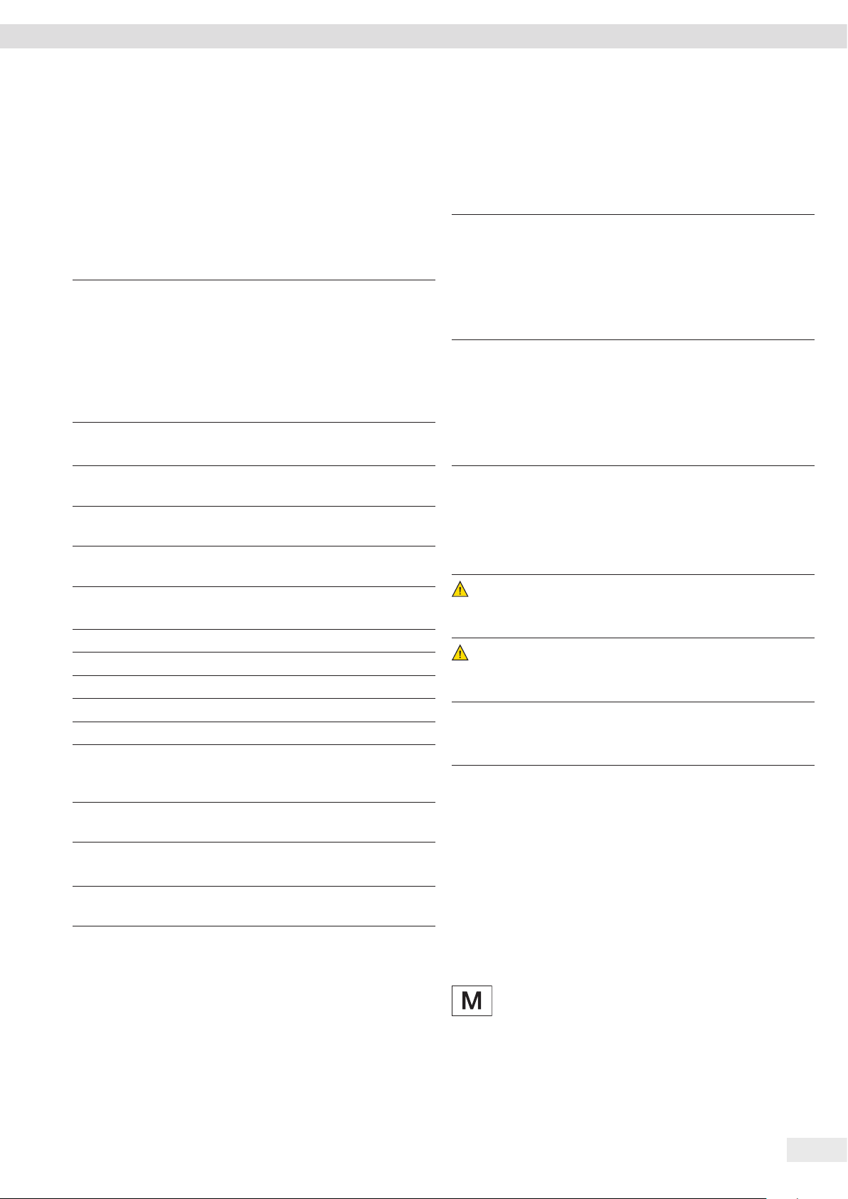
3.1 Device Overview
Fig. 1: Precision balance (front view)
Pos. Designation Description
1 Weighing pan For placing the sample on the
balance
2 Shock absorber
3 Frame draft shield
4 Manufacturer’s
ID label
5 Control unit
6 Level
7 Leveling foot Used to level the balance,
Not visible
manually adjustable
3.2 Device Connections
1
2
3
4
21 3 5
5
6
7
Fig. 2: Precision balance (rear view)
Pos. Designation Description
1 Menu access
switch
2 Power supply Connection for power supply to the
3 USB-C connection For the connection to a printer, PC,
4 RS232 connection 9-pin, for the connection to a
5 Slot For attaching an anti-theft device
Protects the device from changes
to the device settings. Is sealed for
conformity-assessed devices.
device
or a second display
printer, PC, or a second display
or a Kensington lock
4
3.3 Conformity-Assessed Devices
8 Entris® BCE Operating Instructions
Some settings of conformity-assessed models are protected
against user changes, e.g. external calibration for devices in
accuracy class II. This measure is intended to ensure the
suitability of the devices for use in legal metrology.
3.4 Symbols on the Device
Symbol Meaning
NOTICE! Read the operating
instructions.
Page 9
Operating Concept
4 Operating Concept
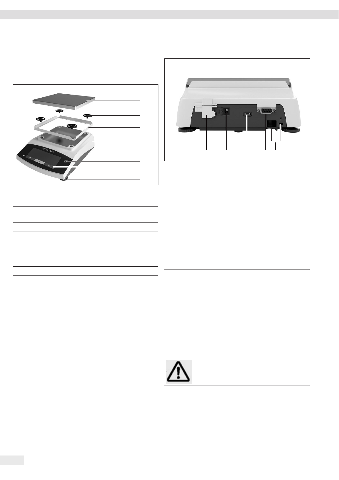
4.1 Operating Display in Weighing Mode
1
2
9
Fig. 3: Operating display in weighing mode (example)
Pos. Designation Description
1 Metrological data
2 Menu
3 Application
overview
4 Toolbar
5 Weighing unit Displays the selected unit,
6 Navigation bar For navigation in the menu and
7 Measurement
display
8 Visual touch
feedback
9 Toolbar
3
8
7
Displays the selected application
program during operation
e.g. grams, [g]
system settings
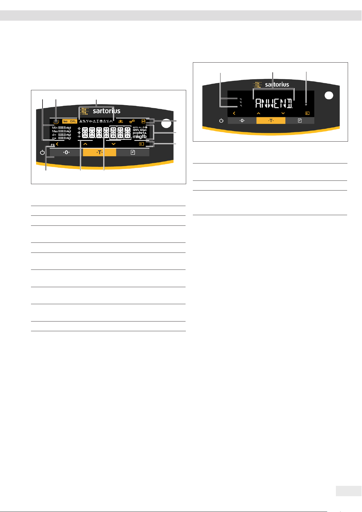
4.2 Menu and System Settings Display
1
4
5
6
Fig. 4: Menu and System Settings Display (example)
Pos. Designation Description
1 Menu or
parameter entry
2 [Selection] display
3 Menu level Shows the position of the
2
displayed menu or parameter
in up to 4 levels
3
Entris® BCE Operating Instructions 9
Page 10
Operating Concept
4.2.1 Buttons
Symbol Designation Description
[On/Off] button − When the button is pressed: Switches the operating display on.
− If the button is held down: Switches the operating display off.
[Menu] button − When the button is pressed: The settings menu opens.
− If the button is held down: It switches to version display.
[Zero] button Zeroes the device.
[Tare] button Starts taring.
[Print] button Exports the readouts to the integrated data interfaces.
[isoCAL] button If the button is flashing: Starts the isoCAL function.
If the button is not flashing: Starts the set calibration and adjustment function.
[Adjust] button Starts the set calibration and adjustment function.
[GLP] button − Exits the GLP printout and starts printing the GLP footer.
− If the “Net-total”, “Totalizing”, or “Statistics” application is active: Prints and deletes the
saved values and exits the application.
[Ambient condition]
Switches between the ambient conditions “V.STABLE”, “STABLE”, UNSTABL.” and “V.UNSTBL.”.
button
[Application filter]
Switches between the “weighing” and “filling” application filters.
button
[Toggle between
weight units] button
If the “Toggle between weight units” function is active:
− If the button is held down: Accesses the “Toggle between weight units” function menu.
− When the button is pressed: Switches between the basic unit display and up to 4 other
units.
[Back] button − In the menu:
− When the button is pressed: Returns to the previous display.
− If the button is held down: Saves the menu settings.
− When entering digits: Selects the previous digit position.
− For an active application: Exits the application and deletes the set reference value.
[Up] button − In the menu: Scrolls through the menu levels or the available parameters.
− When entering digits: Increases the displayed value.
− In the main display of an active application: Switches to the display of the current weight
value/parameter.
[Down] button − In the menu: Scrolls through the menu levels or the available parameters.
− When entering digits: Decreases the displayed value.
− In the main display of an application that is not active: Accesses the display to set the
reference values.
− In the main display of an active application: Switches to the display of the current weight
value/parameter.
[Confirm] button − In the menu: Accesses the displayed menu level or confirms the displayed parameter.
− When entering digits: Selects the next digit position.
− In the main display of an application that is not active: Starts the application process and
saves the set reference value.
− In the main display of an active application: Adopts the next component or the next
parameter.
10 Entris® BCE Operating Instructions
Page 11
4.3 Displays in the Operating Display
Symbol Designation Description
[Counting] display Indicates that the “Counting” application is selected.
Operating Concept
[Weighing in percent]
display
[Calculation] display Indicates that the “Calculation” application is selected.
[Animal weighing]
display
[Net-total] display Indicates that the “Net-total” application is selected.
[Totalizing] display Indicates that the “Totalizing” application is selected.
[Density determination]
display
[Statistics] display Indicates that the “Statistics” application is selected.
[Peak hold] display Indicates that the “Peak hold” application is selected.
[Checkweighing] display Indicates that the “Checkweighing” application is selected.
[Busy] display Indicates that the device is processing a command.
Indicates that the “Weighing in percent” application is selected.
Indicates that the “Animal weighing” application is selected.
Indicates that the “Density determination” application is selected.
[Sign] display Indicates whether the value being displayed is positive or negative.
[Zero] display For some conformity-assessed devices: Indicates that the device has been zeroed.
[AUTO] display Indicates that the “Animal weighing” application starts automatically.
[Application help]
display
[R12] display Indicates the active range for multi-range balances.
[Printer] display − Indicates that a printer has been detected at the USB port.
[PC-Connect] display − Indicates that a PC or a second display has been detected at the USB port.
[Percent] display Indicates that a percentage value is being displayed.
[Net] display Indicates that a net value is being displayed.
− Indicates the number of components for “Totalizing”, “Net total”, and “Statistics”.
− Indicates the minimum limit “LL” and the maximum limit “HH” during
“Checkweighing”.
− Flashes if the data output is active.
− Flashes if the data connection is active.
Entris® BCE Operating Instructions 11
Page 12
Operating Concept
Symbol Designation Description
[Gross] display Indicates that a gross value is being displayed.
[Selection] display In the menu: Identifies the selected parameter.
If the “Calculation” or “Density determination” application is active: Indicates that a
calculated value is being displayed.
[Unit symbol] display Indicates the set weight unit, e.g. [g] for “grams”.
[Quantity] Indicates that a quantity is being displayed.
[Invalid weight value]
display
− Indicates that the display does not contain a weight value, but is instead the
calculated result of an application, e.g. for the “Totalizing” application.
− For conformity-assessed devices: Indicates a fault. The cause of this fault is displayed
after pressing the [Change] key.
4.4 Menu Structure
4.4.1 “Main Menu” Menu Structure
t Navigating in menus (see Chapter 4.5, page 14).
Level 1 Level 2 Description
SETUP BALANCE Set the functions of the device.
GEN.SERV.
“General services”
DEVICE RS-232
“RS232, 9-pin”
USB
“USB-C”
EXTRAS Define the functions of the operating display.
DATA.OUT.
“Data output”
COM. SBI
“SBI communication”
PRNT.PAR.
“Printout settings”
PC.DIREC.
“Direct transfer of data
(PC)”
Reset the menu to factory settings.
Define the parameters for the COM interface.
Define the parameters for the USB interface.
Configure the automatic data output.
Perform the settings for the printout.
Define the output format for the data exchange between the balance and
the PC.
12 Entris® BCE Operating Instructions
Page 13

Operating Concept
Level 1 Level 2 Description
APPLIC.
“Applications”
WEIGH − Determine the weight value of a sample.
− Activate the functions for all applications.
COUNT Determine the number of parts that have approximately equal weight.
PERCENT
“Weighing in percent”
NET.TOT.
Determine the percentage share of a
sample based on a reference weight.
Carry out the weighing of components for a mixture.
“Net-total”
TOTAL
Add weights of independent weighing processes in a memory.
“Totalizing”
ANIMALW.
“Animal weighing”
CALC.
“Calculation”
DENSITY
Weigh unstable samples, e.g. animals. This program calculates the average of
several measurement cycles.
Calculate the weight using a multiplier or divisor, e.g. for determining the
weight per unit area of paper.
Determine the density of solid samples based on the buoyancy method.
“Density determination”
STATIST.
Save and statistically analyze weights and calculated values.
“Statistics”
CHECK.WG.
Check whether a weight value falls within the specified tolerances.
“Checkweighing”
PEAK.HLD.
Determine the maximum weight value of a sample (peak value).
“Peak Hold”
INPUT DEV.ID. Save the entered ID number for the device.
LOT ID Activate or deactivate the printout of a line for the LOT ID in the GLP
printout. It is possible to enter a LOT ID number or the LOT ID can be
manually entered in the line.
SPL. ID − Activate or deactivate the printout of a line for the SPL. ID in the GLP
printout.
− The entered ID number can be counted up or down with each sample.
DATE Set the date.
TIME Set the time.
PW. USER. Set the user password.
PW. SERV. Activate the service mode.
CAL. WT.
“Calibration weight”
Define the user-defined weight value for the calibration and adjustment
weight.
INTERVAL The SBI output rate can be set from 0 - 9999 seconds.
INFO
“Device information”
VER. NO.
“Version number”
SER. NO.
Display the software version number.
Display the device’s serial number.
“Serial number”
MODEL Display the device’s model ID.
BAC VER. Display the version of the BAC processor.
LANGUAGE Set the menu language of the operating display.
Entris® BCE Operating Instructions 13
Page 14
Installation
4.4.2 “Toggle Between Weight Units” Menu Structure
t Navigating in menus (see Chapter 4.5, page 14).
Level 1 Description
Unit 1 - unit 4 Define the displayed weight unit and the
resolution for the 1st to 4th convertible
unit.
4.5 Navigating the Menus
Procedure
t To open the main menu: Press the [Menu]
button.
t To display menu items or parameters of a
level: Press the [Up] or [Down] button.
t To return to the next higher menu level or
exit the menu: Press the [Back] button.
t To open a displayed menu level or a
displayed parameter: Press the [Confirm]
button.
5 Installation
5.1 Scope of Delivery
Item Quantity
Device 1
Pan support 1
Frame draft shield 1
Power supply unit with country-specific
AC adapters
Operating Instructions 1
Shock absorber 4
5.2 Selecting an Installation Site
Procedure
t Make sure that the following conditions are met at the
installation site:
Condition Features
Ambient
conditions
Setup surface − Stable, even surface with little vibration
Access to parts
relevant to
operation
− Suitability tested (ambient conditions
see Chapter 15.1, page 35)
− Sufficient space for the device (device
space requirements see Chapter “15.9
Device Dimensions”, page 37).
− Sufficient load bearing capacity for the
device (device weight see Chapter
“15.10 Metrological Data”, page 38).
Convenient and safe
1
14 Entris® BCE Operating Instructions
Page 15

Installation
5.3 Unpacking
Procedure
t Unpack the device.
t If the device is stored temporarily: Observe the storage
information (see Chapter 13.1, page 33).
t Keep all parts of the original packaging, e.g. to return the
device.
5.4 Removing the Transport Lock
Procedure
1
t Remove the transport locks (1)
and retain them for later use.
5.6 Acclimatizing the Device
When a cold device is brought into a warm environment:
The temperature difference can lead to condensation from
humidity in the device (moisture formation). Moisture in the
device can lead to malfunctions.
Procedure
t Allow the device to acclimatize for approx. 2 hours at the
installation site. The device must be disconnected from the
power supply beforehand.
5.5 Assembling the Device
Procedure
t Place the frame draft
3
2
1
shield (1) on the balance.
t Attach the shock absorbers (2).
t Place the weighing pan (3)
on top.
Entris® BCE Operating Instructions 15
Page 16

Getting Started
6 Getting Started
6.1 Installing the Power Supply Unit
6.1.1 Assembling the Power Supply Unit
Item number
on packaging
YEPS01-PS8 USA and Japan (US+JP), Europe and Russia
YEPS01-PS9 Argentina (AR), Brazil (BR), Korea (KR)
YEPS01-PS10 China (CN)
Procedure
t Push the power plug adapter as far as you can until it
clicks into place.
t Check whether the power plug adapter is securely locked
in place by pulling it gently.
y If the power plug adapter does not move: It is locked in
place.
Power supply unit YEPS01-15VOW with
connection cable and country-specific
power plug adapters (packed in PE bag
with printed country identification,
e.g. EU)
(EU+RU), Great Britain (UK), India (IN),
South Africa (ZA), Australia (AU), China (CN)
t Select the country-specific
power plug adapter. The
power plug adapter must be
suitable for use with the wall
outlet at the installation site.
t Insert the power plug adapter
into the power supply unit.
The grooved button must be
facing upwards.
6.2 Connecting the Power Supply
Procedure
t
WARNING Severe injuries caused by using defective
power supply cables! Check the power supply cable for
damage, e.g. cracks in the insulation.
t If required: Contact Sartorius Service.
t Check whether the country-specific power plug matches
the power connections at the installation site.
t If required: Replace the country-specific power plug
adapter.
t NOTICE Damage to the device due to excessive input
voltage! Check whether the voltage specifications on the
manufacturer’s ID label match those of the power supply
at the installation site.
t If the input voltage is too high: Do not connect the
device to the power supply.
t Contact Sartorius Service.
t Connect the right angle plug to the “Power Supply”
connection.
t Connect the mains plug to the wall outlet (mains voltage)
at the installation site.
y The [BOOTING] display appears in the operating display.
y The device performs a self-test.
7 System Settings
7.1 Performing System Settings
Default settings can be adjusted for the device and the
applications in order to align with the ambient conditions
and individual operating requirements.
The following settings are necessary to operate the device
together with connected components:
− Set up the communication of the connected devices
− Set up additional components
6.1.2 Dismantling the Power Plug Adapter
Procedure
t Press the grooved button
from above and pull back on
the power plug adapter.
t Push the power plug adapter
out of the power supply unit
and remove it.
16 Entris® BCE Operating Instructions
The following settings are recommended to set up the device:
− Set the menu language
− Set the date and time
− Set the calibration and adjustment
Procedure
t Press the [Menu] button.
t To adjust settings: Open the desired menu.
t Select and confirm the desired parameter (parameters,
see Chapter “7.3 Parameter List”, page 18).
t Exit the menu.
Page 17

System Settings
7.2 Setting the Calibration and Adjustment
7.2.1 Switching the isoCAL Function On or Off
(Only Model i-1x)
When using the isoCAL function, the device performs an
automatic time- and temperature-dependent internal
calibration and adjustment.
If this relates to a conformity-assessed device in
legal metrology: In some cases it is not possible to
switch off the isoCAL function.
Procedure
t Open the “SETUP”/”BALANCE” menu.
t To set the automatic start of the isoCAL function: Select the
“ON” calibration value for the “ISOCAL” parameter.
t To set the manual start of the isoCAL function: Select the
“Note” calibration value for the “ISOCAL” parameter.
t To switch off the isoCAL function: Select the “OFF”
calibration value for the “ISOCAL” parameter.
7.2.2 Setting Internal Calibration and Adjustment
(Only Model i-1x)
The following functions can be set for the internal calibration
and adjustment:
− Internal calibration with automatic start of the adjustment.
− Internal calibration with manual start of the adjustment.
Procedure
t Open the “SETUP”/”BALANCE” menu. Call up the “CAL.JUST.”
parameter and select the value “CAL.INT.”.
t If the calibration function needs to be set with subsequent
automatic adjustment: In the “SETUP”/”BALANCE” menu, for
the “CAL.SEQ.” parameter, select the “ADJUST” setting value.
t If the calibration function needs to be set without
subsequent automatic adjustment: In the
“SETUP”/”BALANCE” menu, for the “CAL.SEQ.” parameter,
select the “CAL./ADJ.” setting value.
7.2.3 Setting the External Calibration and Adjustment
The following functions can be set for the external calibration
and adjustment:
− External calibration with manual start of the adjustment.
If this relates to a conformity-assessed device in
legal metrology: External calibration and adjustment is not possible.
Procedure
t Open the “SETUP”/”BALANCE” menu.
t If the calibration function needs to be set with subsequent
automatic adjustment: Select the “ADJUST” calibration
value for the “CAL.SEQ.” parameter.
t If the calibration function needs to be set without
subsequent automatic adjustment: Select the “CAL-ADJUST”
calibration value for the “CAL.SEQ.” parameter.
Setting the Weight Value for the External Weight
A preset weight value or a user-defined weight value can be set
for the external weight.
Procedure
t If the preset weight value needs to be used: In the
“SETUP”/”BALANCE” menu, for the “CAL./ADJ.” parameter,
select the “EXT.CAL.” setting value.
t If a user-defined weight value needs to be set:
t In the “INPUT” menu, select the “CAL.WT.” setting value.
t Enter the desired weight value and press the [Confirm]
button.
t To use the user-defined weight value for the next
calibration: In the “SETUP”/”BALANCE” menu, for the
“CAL./ADJ.” parameter, select the “E.CAL.USR” setting
value.
Entris® BCE Operating Instructions 17
Page 18

System Settings
7.3 Parameter List
7.3.1 “SETUP”/”BALANCE” Menu
Parameter Setting values Explanation
AMBIENT V.STABLE Sets the ambient conditions to “very stable”: Activates a fast change in the weight values in
the event of a load change with a high output rate.
Recommended for the following work environment:
− Very stable table near the wall
− Closed and calm room
STABLE* Sets the ambient conditions to “stable”. Recommended for the following work environment:
− Stable table
− Slight movement in the room
− Slight draft
UNSTABL. Sets the ambient conditions to “unstable”: Activates the delayed change in weight values with
a reduced output rate. Recommended for the following work environment:
− Simple office desk
− Room with moving machinery or personnel
− Slight air movement
V.UNSTBL. Sets the ambient conditions to “very unstable”: Activates a significantly delayed change in the
weight values and long wait for stability with a further reduction in the output rate.
Recommended for the following work environment:
− Noticeable and slow floor vibrations
− Noticeable building vibrations
− Weighed goods moved
− Very strong air movements
APP FILT. FINAL.RD.* Activates a filter that enables a fast change in the display for very fast load changes.
Display changes with minimal load changes (in the digit range) occur more slowly.
FILLING Activates a filter that enables a very fast change in the display with minimal load changes,
e.g. when filling containers.
STABIL. V. ACC. Sets the stability to “very accurate”.
ACC.* Sets the stability to “accurate”.
FAST Sets the stability to “fast”.
ZER./TAR. W/O STB. If the button is pressed: The function of the [Zero] or [Tare] button is executed immediately.
W/ STAB.* The function of the [Zero] or [Tare] button is only executed after stability is achieved.
AUTOZER. ON* Activates automatic zeroing. The display is automatically set to zero in case of a deviation of
0 less than (X).
OFF Deactivates automatic zeroing. Zeroing must be triggered with the [Zero] button.
* Factory setting
18 Entris® BCE Operating Instructions
Page 19

System Settings
Parameter Setting values Explanation
UNIT GRAM*,
KILOGR., CARAT,
− The device displays the weight in the selected unit.
− The availability of units depends on national legislation and is therefore country-specific.
POUND,OUNCE,
TROY.OZ.,
HKTAEL,
SNGTAEL,
TWNTAEL,
GRAINS,
PENNYWT.,
MILLIGR., PART./
LB, TL./CHINA,
MOMMES,
AUSTR.CT, TOLA,
BAHT,
MESGHAL,
NEWTON
DISP.DIG. ALL* “Show all decimal places”: All decimal places are shown in the display. The setting change is
not available on conformity-assessed devices.
LP.ON.OFF “Reduced by 1 decimal place for load change”: The last decimal place on the display is switched
off until stability is achieved.
MINUS 1 “Last decimal place off”: The last decimal place is switched off.
CAL./ADJ. EXT.CAL. The [Adjust] button starts an external calibration and adjustment process with the preset
calibration weight.
E.CAL.USR. The [Adjust] button starts an external calibration and adjustment process with the user-
defined calibration weight value.
INT.CAL.* The [Adjust] button starts an internal calibration and adjustment process.
CAL.SEQ. ADJUST* The adjustment starts automatically after the calibration.
CAL.-ADJ. The adjustment must be started or exited manually after calibration with the [Confirm] button.
ON Z/T ON* Activates the initial taring/zeroing. The device is tared or zeroed after it is switched on.
OFF Deactivates the initial taring/zeroing: After it is switched on, the device shows the same value
as before it was last switched off.
ISOCAL OFF Switches the isoCAL function off.
NOTE If the balance needs to be calibrated: The [isoCAL] button flashes. The isoCAL function must be
manually triggered with the [Adjust] button.
ON* Activates the isoCAL function. The device is automatically adjusted as soon as a trigger starts
the isoCAL function.
EXT.CAL. UNLOCKED* Activates the external calibration/adjustment function under [CAL./ADJ.].
LOCKED Deactivates the external calibration/adjustment function under [CAL./ADJ.].
* Factory setting
7.3.2 “SETUP”/”GEN.SERV.” Menu
Parameter Setting values Explanation
MENU.RES. YES Resets the system settings to the factory default settings.
NO* Deactivates the option of resetting the device menu.
* Factory setting
Entris® BCE Operating Instructions 19
Page 20

System Settings
7.3.3 “DEVICE”/”RS232” Menu
Parameter Setting values Explanations
DAT.REC. XBPI Extended range of commands to control numerous balance functions with binary protocol for
direct communication with the device.
SBI* Enables SBI communication. The data is output to a PC or control unit. Enables the use of ESC
commands from a PC to control the basic balance functions with ASCII protocol.
REM.DISP. Enables data output on another display.
BARCODE Allows for the connection of an approved barcode scanner.
YDP20 Sets the standard settings of YDP20 printers.
YDP30 Sets the standard settings of YDP30 printers.
OFF Deactivates the automatic data output.
BAUD 600, 1200,
Sets the baud rate to the selected value.
2400, 4800,
9600*, 19200,
38400, 57600,
115200
PARITY ODD* Applies an odd parity.
EVEN Applies an even parity.
NONE Does not apply a parity.
STOPBIT 1 BIT* Sets the number of stop bits to 1.
2 BITS Sets the number of stop bits to 2.
HANDSHK. SFTWARE Sets the handshake protocol to software handshake.
HRDWARE* Sets the handshake protocol to hardware handshake.
NONE Does not set a handshake protocol.
DATABIT 7 BITS Sets the number of data bits to 7.
8 BITS* Sets the number of data bits to 8.
* Factory setting
7.3.4 “DEVICE”/”USB” Menu
Parameter Setting values Explanations
DAT.REC.** XBPI Extended range of commands to control numerous balance functions with binary protocol for
direct communication with the device.
SBI* Enables SBI communication. The data is output to a PC or control unit. Enables the use of
ESC commands from a PC to control the basic balance functions with ASCII protocol.
REM.DISP. Enables data output on another display.
PC.SPREA. Enables data output to a spreadsheet program via a direct PC connection.
YDP20 Sets the standard settings of YDP20 printers.
YDP30 Sets the standard settings of YDP30 printers.
PC.TEXT The balance transmits the data via keyboard command to the currently opened application on
the PC in text format.
OFF Deactivates the data output.
* Factory setting
** Are blocked if “PRINTER” or “REM.DISP.” are displayed under “DEV.USED”
20 Entris® BCE Operating Instructions
Page 21

System Settings
Parameter Setting values Explanations
BAUD** 600, 1200,
Sets the baud rate to the selected value.
2400, 4800,
9600*, 19200,
38400, 57600,
115200
PARITY** ODD* Applies an odd parity.
EVEN Applies an even parity.
NONE Does not apply a parity.
STOPBIT** 1 BIT* Sets the number of stop bits to 1.
2 BITS Sets the number of stop bits to 2.
HANDSHK.** SFTWARE Sets the handshake protocol to software handshake.
HARDW. Sets the handshake protocol to hardware handshake.
NONE* Does not set a handshake protocol.
DATABIT** 7 BITS Sets the number of data bits to 7.
8 BITS* Sets the number of data bits to 8.
DEV.USED NONE*,
Indicates which connection is detected at the USB port.
PRINTER, VIRT.
COM, PC HOST,
REM.DISP.
* Factory setting
** Are blocked if “PRINTER” or “REM.DISP.” are displayed under “DEV.USED”
7.3.5 “DEVICE”/”EXTRAS” Menu
Parameter Setting values Explanation
MENU EDITABL.* Activates write access. The menu parameters can be changed.
RD.ONLY Activates read access. The menu parameters cannot be changed.
SIGNAL OFF Switches the acoustic signal off.
ON* Switches the acoustic signal on.
KEYS UNLOCKED* Deactivates the button lock.
LOCKED Activates the button lock.
EXT.KEYB.
PRINT Assigns the print function to the external key.
CAL. Assigns the calibration and adjustment function selected under [CAL./ADJ.] to the external
key.
CF Assigns the [Back] function to the external key.
ENTER Assigns the [Confirm] function to the external key.
ZERO Assigns the [Zero] function to the external key.
TARE Assigns the [Tare] function to the external key.
APP Assigns the [From] function to the external key. The function is triggered for an application
that is not active.
GLP END Assigns the [GLP] function to the external key.
NONE* No function is assigned to the external key.
ON MODE
ON/STDB.* The [On/Off] button switches between on/standby with time.
ON/OFF The [On/Off] button switches between on/standby without time..
AUTO ON Changes the function of the [On/Off] button: The device no longer switches off or to standby
mode, instead it starts a boot process.
* Factory setting
Entris® BCE Operating Instructions 21
Page 22

System Settings
Parameter Setting values Explanation
LIGHT
OFF Deactivates the lighting on the operating display.
ON* Activates the lighting on the operating display.
* Factory setting
7.3.6 “DATA.OUT.”/”COM. SBI” Menu
Parameter Setting values Explanations
COM. OUTP. IND.NO* Activates the manual data output without stability.
IND.AFTR Activates the manual data output after stability.
AUTO.W/O Activates the automatic data output without stability.
AUTO W/ Activates the automatic data output after stability.
STOP.AUT. OFF* Deactivates the option to abort the automatic data output.
ON The automatic data output is aborted by pressing the [Print] button or a software command.
AUTO.CYCL. EACH VAL* Starts the automatic data output with a cycle after each value.
AFTER 2 Starts the automatic data output with a cycle after every 2nd value.
INTERV. The output rate can be set from 0 - 9999 seconds under “INPUT/INTERV.”.
FORMAT 22 CHARS* The data output provides 22 characters per line (16 characters for the measured value and
6 characters for identifiers).
16 CHARS The data output provides 16 characters per line for the measured value.
EXTR.LIN. The data output provides an additional line with the date, time, and weight value.
AUTO.TAR. OFF* Deactivates automatic taring after data output.
ON The device automatically tares after data output.
* Factory setting
7.3.7 “DATA.OUT.”/”PRNT.PAR.” Menu
Parameter Setting values Explanation
ACTIVAT. MAN. NO Manual without stability: The print process can be started manually at any time.
MAN.AFTR* Manual after stability: After pressing the [Print] button, the print command is only executed
once stability is achieved.
INTERV. The output rate can be set from 0 - 9999 seconds under “INPUT/INTERV.”.
AUTO.LC Automatically at load change: The print process starts after every load change.
FORMAT 22 CHARS* The printer output prints 22 characters per line (16 characters for the measured values and
6 characters for identifiers)
EXTR.LIN. The printer output prints an additional line with the date, time, and weight value.
PRT.INIT. OFF Deactivates the output of the application parameters.
ALL* The print command prints all parameters.
MAIN.PAR. The print command only prints the main parameters.
GLP OFF* Deactivates the GLP printout.
CAL./ADJ. Activates the GLP printout for all calibration and adjustment processes.
ALWAYS The GLP printout is always switched on. All printouts contain a GLP header and a GLP footer.
TAR./PRT. OFF* Deactivates automatic taring after printer output.
ON Automatically tares the device after every printout.
* Factory setting
22 Entris® BCE Operating Instructions
Page 23

System Settings
Parameter Setting values Explanation
TIME 24H* Sets the time to 24-hour mode.
12H − Sets the time to 12-hour mode (AM/PM).
− Is blocked for ISO format.
DATE DD.MMM.YY* Sets the date display format to DD.MMM.YY
MMM.DD.YY Sets the date display format to MMM.DD.YY
YY.MM.DD − Sets the date display format to ISO FORMAT YYYY-MM-DD.
− Sets the time to 24-hour mode.
* Factory setting
7.3.8 “DATA.OUT.”/”PC.DIREC.” Menu
Parameter Setting values Explanations
DEC.SEP. POINT* Sets a point as a decimal separator.
COMMA Sets a comma as a decimal separator.
OUT.FORM. TXT+NUM.* Exports text and numbers.
ONLY.NUM. Only exports numbers.
* Factory setting
7.3.9 “APPLIC.”/”WEIGH” Menu
Parameter Setting values Explanation
UNIT ON* Activates the “Toggle between weight units” touch function.
OFF Deactivates the “Toggle between weight units” touch function.
RECALL ON Activates the saving of the last stable weight value not equal to 0.
OFF* Deactivates saving.
APP FILT. ON* Activates the “Application filter” touch function.
OFF Deactivates the “Application filter” touch function.
AMBIENT ON* Activates the “Ambient conditions” touch function.
OFF Deactivates the “Ambient conditions” touch function.
* Factory setting
7.3.10 “APPLIC.”/”COUNT” Menu
Parameter Setting values Explanation
RESOLUT. DISP.ACC.* Sets the resolution to “display resolution”. The “Counting” application is started with the
displayed value.
10-FOLD Sets the resolution to 10-times more accurate than “display resolution”.
100-FOLD Sets the resolution to 100-times more accurate than “display resolution”.
REF.UPDT. OFF* Deactivates automatic reference sample updating.
AUTO Activates the automatic reference sample updating.
* Factory setting
Entris® BCE Operating Instructions 23
Page 24

System Settings
7.3.11 “APPLIC.”/”PERCENT” Menu
Parameter Setting values Explanation
DEC.PLCS NONE The result of the “Weighing in Percent” application is displayed without decimal places.
1 DEC.PL.* The result of the “Weighing in Percent” application is displayed to 1 decimal place.
2 DEC.PL. The result of the “Weighing in Percent” application is displayed to 2 decimal places.
3 DEC.PL. The result of the “Weighing in Percent” application is displayed to 3 decimal places.
* Factory setting
7.3.12 “APPLIC.”/”NET.TOT.” Menu
Parameter Setting values Explanation
PRT.COMP. OFF Deactivates the component printout.
ON* Activates the component printout.
* Factory setting
7.3.13 “APPLIC.”/”TOTAL” Menu
Parameter Setting values Explanation
PRT.COMP. OFF Deactivates the component printout.
ON* Activates the component printout.
* Factory setting
7.3.14 “APPLIC.”/”ANIM.WG” Menu
Parameter Setting values Explanation
ACTIVIT. CALM Sets the intensity of the “Animal activity” to “calm”. Recommended for minor movements of
the sample, e.g. caused by placement on the weighing pan.
MEDIUM* Sets the intensity of the “Animal activity” to “medium”. Recommended for medium movements
of the sample, e.g. caused by placement on the weighing pan.
V.ACTIVE Sets the intensity of the “Animal activity” to “very active”. Recommended for very active
movements of the sample, e.g. caused by placement on the weighing pan.
START MANUAL The “Animal weighing” application must be manually selected in the start screen.
AUTO* Sets the trigger to start the “Animal weighing” application to “automatic”.
* Factory setting
7.3.15 “APPLIC.”/”CALC.” Menu
Parameter Setting values Explanation
METHOD MUL.* Specifies multiplication as the method of calculation for the “Calculation” application.
DIV. Specifies division as the method of calculation for the “Calculation” application.
* Factory setting
24 Entris® BCE Operating Instructions
Page 25

System Settings
Parameter Setting values Explanation
DEC.PLCS NONE The result of the “Calculation” application is displayed without decimal places.
1 DEC.PL.* The result of the “Calculation” application is displayed to 1 decimal place.
2 DEC.PL. The result of the “Calculation” application is displayed to 2 decimal places.
3 DEC.PL. The result of the “Calculation” application is displayed to 3 decimal places.
* Factory setting
7.3.16 “APPLIC.”/”DENSITY” Menu
Parameter Setting values Explanation
DEC.PLCS NONE The result of the “Density determination” application is displayed without decimal places.
1 DEC.PL.* The result of the “Density determination” application is displayed to 1 decimal place.
2 DEC.PL. The result of the “Density determination” application is displayed to 2 decimal places.
3 DEC.PL. The result of the “Density determination” application is displayed to 3 decimal places.
* Factory setting
7.3.17 “APPLIC.”/”STATIST.” Menu
Parameter Setting values Explanation
PRT.COMP. OFF Deactivates the component printout.
ON* Activates the component printout.
TAR.STAT. OFF* Deactivates automatic taring after the components are saved.
ON Activates automatic taring after the components are saved.
* Factory setting
7.3.18 “APPLIC.”/”PEAK.HLD.” Menu
Parameter Setting values Explanation
APPLY AT STAB.* Peak values are applied when there is stability.
W/O STB. Peak values are applied without stability.
* Factory setting
7.3.19 “APPLIC.”/”CHECK.WG.” Menu
Parameter Setting values Explanation
INPUT MANUAL* The min/max limits are entered manually.
WG.VALUE The entry of the min/max limits is carried out by applying the weight value.
AUTO.PRT. OFF* The automatic printing is switched off.
ON With automatic printing, all values are exported.
OK ONLY With automatic printing, only values that are within the control range are exported.
NOT OK With automatic printing, only values that are outside the control range are exported.
* Factory setting
Entris® BCE Operating Instructions 25
Page 26

System Settings
7.3.20 “INPUT” Menu
Parameter Setting values Setting values Explanation
DEV. ID Max 14
Saves the entered ID number for the device.
characters 09-0,
A-Z, - , empty
LOT ID PRINT ON Activates the output of the lot ID number during GLP output.
OFF* Deactivates the output of the lot ID number during GLP output.
CONTENT** Max 14
Content of the LOT ID.
characters 09-0,
empty
SPL. ID PRINT ON Activates the output of the SPL. ID number during GLP output.
OFF* Deactivates the output of the SPL. ID number during GLP output.
START**** Max 14
Start value of the SPL. ID.
characters 09-0,
A-Z, - , empty
MODE** COUNT.UP* The SPL. ID number is counted up on each printout.
COUNT.DN The SPL. ID number is counted down on each printout.
SCAN*** The SPL. ID number is read in by the barcode scanner. Printing then occurs
automatically.
DATE Saves the entered date.
TIME Saves the entered time.
PW. USER Max 7
Saves the entered user password.
characters 09-0,
A-Z, - , empty
PW. DEL.**** YES Deletes the entered password.
NO* Does not delete the entered password.
PW. SERV. Max 7
Activates service mode.
characters 09-0,
A-Z, - , empty
CAL.WT. Changes the calibration weight for the adjustment or calibration process with
the user-defined weight value.
INTERV. The SBI output rate can be set from 0 - 9999 seconds.
* Factory setting
** Only visible if “PRINT”/”ON” is selected
*** Only possible if “BARCODE” is selected (see Chapter “7.3.3 “DEVICE”/”RS232” Menu”, page 20)
**** Only visible if “SPL. ID”/”MODE”/”SCAN” is not selected. Only visible if the user password is available.
7.3.21 “INFO” Menu
Parameter Setting values Explanation
VER. NO. Displays the version number of the control module.
SER. NO. Displays the serial number of the device.
Model Displays the type designation of the device.
BAC VER. Displays the version number of the weight sensor.
* Factory setting
26 Entris® BCE Operating Instructions
Page 27

Operation
7.3.22 “LANGUAG.” Menu
Parameter Setting values Explanation
Language ENGLISH,
DEUTSCH,
FRANC.
ITAL., ESPANOL,
PORTUG.,
РYССKИИ,
POLSKI
* Factory setting
Defines the menu language.
8 Operation
8.1 Switching the Device On and Off
Requirements
The device is connected to the power supply.
Procedure
t
CAUTION Pointed or sharp-edged objects may damage
the operating display!
t Only touch the operating display with your fingertips.
t To switch the device on: Press the [On/Off] button.
t To switch the device off: Press and hold the [On/Off]
button.
8.3 Leveling the Device with a Level Indicator
Unevenness at the installation site of the device may result in
incorrect weighing results. Leveling balances out unevenness at
the installation site.
Procedure
t Unscrew the rear leveling
feet, until they touch the
setup surface.
y The support foot (1) is not in
contact with the setup
surface.
t To level the device: Bring the
air bubble of the level
1
t Check that the device is standing on 4 leveling feet and
the support foot (1) is not in contact with the setup
surface.
indicator into the middle of
the circular marking. To do so,
turn the leveling feet to the
left or right.
8.4 Overview of Calibration and Adjustment
During calibration, a calibration weight is used to determine
the deviation of the displayed value from the actual value.
The subsequent adjustment eliminates this deviation.
We recommend regular calibration and adjustment:
8.2 Waiting for the Warm-up Time
In order to provide accurate weighing results, the device
must have reached the necessary operating temperature.
The operating temperature is reached after the warm-up time.
The warm-up time starts when the device is switched on.
Procedure
t Switch on the device.
t Wait until the operating temperature is reached (warm-up
time see Chapter “15.7 Warm-up Time”, page 37).
If a weighing process is carried out on a conformityassessed device during the warm-up time:
The weight value is marked as invalid.
− Daily, every time the device is switched on
− After every leveling
− After changing the ambient conditions (temperature,
humidity, or air pressure)
− After setting the device up at a new installation site
8.5 Calibrating and Adjusting Device with
isoCAL Function (Only Model i-1x)
Triggers for the automatic start of the isoCAL function are:
− The ambient temperature has changed since the last
adjustment process.
− The interval time was exceeded (interval time, see Chapter
“15.7 Warm-up Time”, page 37).
If this relates to a conformity-assessed model:
The device has been disconnected from the power
supply since the last adjustment.
Entris® BCE Operating Instructions 27
Page 28

Operation
Requirements
− The automatic or manual start of the isoCal function is set
in the menu (see Chapter “7.2.1 Switching the isoCAL
Function On or Off (Only Model i-1x)”, page 17).
− The device is not located in the menu settings.
− The load on the weighing pan remains unchanged for
2 minutes.
− The load on the scales amounts to no more than 2% of the
maximum load.
− The device does not register an input for 2 minutes.
Procedure
t If the automatic start of the isoCAL function is triggered:
y The [isoCAL] button flashes in the operating display.
y The operating display shows “CAL.” for 19 seconds.
y If no load change or no operation takes place on the
device before the expiration of the time display:
The isoCAL function starts.
t If the manual start of the isoCAL function is triggered:
y The [isoCAL] button flashes in the operating display.
t Press the [isoCAL] button.
y The isoCAL function starts.
8.6 Calibrating and Adjusting the Device
Internally (Only Model i-1x)
Requirements
− The weighing pan is unloaded.
− The operating display shows a stable weight value.
− The internal calibration and adjustment function is set
(see Chapter “7.2.2 Setting Internal Calibration and
Adjustment (Only Model i-1x)”, page 17).
Procedure
t Press the [Zero] button.
t Press the [Adjust] button.
y The weight value is displayed.
t If the calibration function with subsequent automatic
adjustment is selected:
y The “CAL.RUN.” display appears in the operating display
during the process.
y The “CAL.END” display indicates the end of calibration.
t If the calibration function without subsequent automatic
adjustment is selected:
t Press the [Confirm] button.
y The calibration process starts.
y The “CAL.RUN.” display appears in the operating display
during the process.
y The calibration error is displayed.
t Press the [Confirm] button.
y The adjustment is performed.
y The “CAL.END” display indicates the end of calibration.
8.7 Externally Calibrating and Adjusting the
Device
Material Calibration and adjustment weight
Requirements
− The weighing pan is unloaded.
− The operating display shows a stable weight value.
− The external calibration and adjustment function is set
(see Chapter 7.2.3, page 17).
− The preset weight value for the adjustment weight or the
user-defined weight value for the adjustment weight is
selected (see Chapter 7.2.3, page 17).
Procedure
t Press the [Zero] button.
t Press the [Adjust] button.
t Place the indicated calibration and adjustment weight on
the balance.
y The weight value is displayed.
t If the calibration with subsequent automatic adjustment
function is selected and the calibration weight placed on
the device is within the specified limits:
y The adjustment process starts.
y If the “+” prefix was displayed: The applied weight is
too big.
y If the “-” prefix was displayed: The applied weight is
too small.
y The “CAL.END” message indicates the end of calibration.
t Remove the calibration weight.
t If the calibration without subsequent automatic adjustment
function is selected and the calibration weight placed on
the device is within the specified limits:
t Press the [Confirm] button.
y The adjustment process starts.
y If the “+” prefix was displayed: The applied weight is
too big.
y If the “-” prefix was displayed: The applied weight is
too small.
y The “CAL.END” message indicates the end of calibration.
t Remove the calibration weight.
8.8 Printing Results of the Calibration and
Adjustment Process
The results of the calibration and adjustment process can be
printed in a GLP printout.
Procedure
t Set the GLP printout in the menu (setting parameters,
see Chapter 7.3.7, page 22).
t Calibrate the device.
y Once the calibration is complete: The printing process starts.
28 Entris® BCE Operating Instructions
Page 29

Operation
8.9 Weighing
Requirements
− The device has been leveled.
− The device is calibrated and adjusted.
NOTICE
Chemicals may damage the device or accessories!
Chemicals can attack the device or the connected accessories
internally and externally. This may damage the device and
accessories.
t Use appropriate containers when weighing chemicals.
Procedure
t Zero the device. In order to do so, press the [Zero] button.
t If a container is being used for the sample:
t Tare the device. In order to do so, press the [Tare]
button.
t Place the sample in the container.
t If no container is used for the sample: Place the sample on
the weighing pan.
y The weight value is displayed depending on the selected
application program.
8.10 Setting or Changing an Application
Procedure
t In the “APPLIC.” menu, select an application, e.g. “STATIST.”
t Press the [Confirm] button.
t Exit the menu.
Procedure
t To switch the displayed weight unit during weighing or
before an application: Press the [Toggle between weight
units] button until the desired unit is displayed.
y The current weight value is displayed in the selected unit.
8.11.2 Selecting Convertible Units and their Decimal
Places
Procedure
t Press and hold down the [Toggle between weight units]
button.
t Select one of the parameters “Unit 1“ – “Unit 4” in the
submenu. To do so, press the [Confirm] button.
t Select the desired unit. To do so, press the [Confirm] button.
t Specify the decimal places for the selected unit. To do so,
press the [Confirm] button once again.
t Select the desired number of display digits. To do so, press
the [Confirm] button.
8.11.3 Running the “Statistics” Application
The “Statistics” application saves up to 99 weight values and
evaluates these statistically.
The following values are saved and exported:
− Number of components
− Mean value
− Standard deviation
− Variation coefficient
Sum of all values
− Lowest value (minimum)
− Highest value (maximum)
− Spread: Difference between maximum and minimum
8.11 Running Applications (Examples)
8.11.1 Executing the “Toggle Between Weight Units”
Function
The “Toggle between weight units” function enables a switch
between a maximum of four different units. The selected basic
unit is displayed every time the device is started (see “UNIT”,
Chapter “7.3.1 “SETUP”/”BALANCE” Menu”, page 18). The
units can be set during the weighing process and the decimal
places can be adjusted.
Requirements
The “Toggle between weight units” function is activated (see
Chapter “7.3.9 “APPLIC.”/”WEIGH” Menu”, page 23).
The weight value must be valid.
Requirements
− A printer or a PC is connected and configured.
− The “STATIST.” application is selected.
Procedure
t Place a sample on the weighing pan.
t To save the weight value: Press the [Confirm] button.
y The position of the saved value is displayed, e.g. “NO 1”.
y The recording of the statistics starts.
t Remove the sample on the weighing pan.
t To save the next value:
t Place a new sample on the weighing pan and press the
[Confirm] button.
t To switch between the display of the current weight value,
the number of saved components, and the calculated mean
in the results display: Press the [Up] or [Down] button.
t To delete all saved values: Press the [Back] button.
y The evaluation is printed and the active GLP print is ended.
t To print and exit the current statistics, and to delete the
saved values: Press the [GLP] button.
Entris® BCE Operating Instructions 29
Page 30

Cleaning and Maintenance
8.12 Printing Weighing Result with ID Marking
The device, the sample and a batch can be assigned an ID
number. The ID numbers are exported during GLP-compliant
printing.
Requirements
− The identity number is specified (see Chapter “7.3.20
“INPUT” Menu”, page 26).
− The printing of the lot ID line in the GLP printout is
activated in the menu (see Chapter “7.3.20 “INPUT” Menu”,
page 26).
− The “SPL. ID” output is activated in the menu.
− The GLP-compliant printout is activated (see Chapter “7.3.7
“DATA.OUT.”/”PRNT.PAR.” Menu”, page 22).
Procedure
t Start the printout. To do so, press the [Print] button.
y The GLP header is printed with the ID marking of the
LOT ID set in the menu and the current weight value.
y The [GLP] button appears in the operating display.
t Confirm the [PRINT] button.
y The SPL. ID and the current weight value are exported.
t Confirm the [PRINT] button.
y The SPL. ID and the current weight value are exported.
t To exit the GLP printout: Press the [GLP] button.
y The GLP footer is printed.
9.2 Cleaning the Device
NOTICE
Corrosion or damage to the device due to unsuitable
cleaning agents!
t Do not use corrosive, chloride-containing, or aggressive
cleaning agents.
t Do not use cleaning agents that contain abrasive
ingredients, e.g. scouring agents, steel wool.
t Do not use solvent-based cleaning agents.
t Only use suitable cleaning agents (materials see Chapter
“15.6 Materials”, page 36) and observe the product
information for the cleaning agent used.
Procedure
t NOTICE Malfunction or damage to the device due to the
ingress of moisture or dust!
t Only slightly moisten cleaning materials, such as cloths.
t Remove dust and powdery sample residue with a brush
or hand-held vacuum cleaner.
t Wipe the device and the associated components with a
slightly damp cloth. Use a mild soapy solution or a suitable
cleaning agent for more severe contaminations.
9.3 Assembling the Weighing Pan and
Associated Components
9 Cleaning and
Maintenance
9.1 Removing the Weighing Pan and
Associated Components
Requirements
− The device is switched off.
− The device is disconnected from the power supply.
Procedure
t Remove the weighing pan,
the shock absorbers and
the frame draft shield.
Procedure
t Assemble the weighing pan and the associated components
(see Chapter “5.5 Assembling the Device”, page 15).
t Connect the device to the power supply (see Chapter “6.2
Connecting the Power Supply”, page 16).
9.4 Maintenance Schedule
Interval Component Action
Regularly; depending on
the operating conditions
Device Contact Sartorius
Service.
9.5 Software Update
For a software update, contact Sartorius Service.
30 Entris® BCE Operating Instructions
Page 31

Malfunctions
10 Malfunctions
10.1 Warning Messages
Warning message Fault Cause Remedy Chapter, page
APP.ERR. The device has measured
an invalid weight value.
DIS.ERR. The value to be output
cannot be shown in the
operating display.
HIGH or ERR 55 The device is overloaded. The device’s maximum
LOW or ERR 54 The modulation of the
weighing converter
inside the device is too
low.
COMM.ERR. The device is not
receiving any weight
values.
PRT.ERR. The [Print] key is locked. The data interface for print
SYS.ERR. The system data is
faulty.
ERR 02 The device cannot be
calibrated when starting
the calibration function
due to a zero point
error.
ERR 10 Taring is not possible. The device cannot be
ERR 11 The weight value
cannot be saved in
the tare memory.
The applied weight is too low. Increase the applied weight to
The weight value is negative.
No sample has been placed
on the balance.
The data to be displayed is
not compatible with the set
display format.
weighing capacity has been
exceeded.
No weighing pan has been
placed on the balance.
A previously forgotten weight
was removed after starting
the device.
An error exists in the
weighing system or in
the device electronics.
No communication exists
between the control module
and the weigh cell.
output is set to xBPI mode.
A memory error exists in
the control module.
The device was not zeroed
before calibration.
The device is loaded. Remove the sample from the
manually tared because an
application program has the
tare memory reserved.
The weight value is negative
or “zero”.
more than the minimum load.
Place the sample on the balance.
Adjust the display settings in
the menu, e.g. resolution, unit,
decimal places.
Reduce the applied weight to
below the device’s maximum
weighing capacity.
Insert the weighing pan into the
device and switch the device off
and on again.
Contact Sartorius Service.
Wait until the control module
restores the communication
with the weigh cell.
If the problem occurs again:
Contact Sartorius Service.
Reset the menu to the factory
settings.
If the problem occurs again:
Contact Sartorius Service.
Switch the device off and on
again.
If the problem occurs again:
Contact Sartorius Service.
Zero the device.
Check the preload and set if
necessary.
weighing pan.
To release the tare memory:
Exit the application program
with the [Back] button.
Check the sample being weighed.
Zero the device before placing
the sample on the balance if
necessary.
Entris® BCE Operating Instructions 31
Page 32

Malfunctions
10.2 Troubleshooting
Fault Cause Remedy Chapter, page
The operating display is
blank.
The displayed weight value
changes constantly.
The weight readout
displayed by the device
is obviously wrong.
For a conformity-assessed
device: The [Invalid weight
value] display appears.
The device is disconnected. Check the connection to the power
supply.
The power supply unit is not
connected.
The installation site is unstable. Adjust the parameter for the ambient
A foreign object is positioned
between the weighing pan and
the housing.
The device has not been calibrated
and adjusted.
The device was not tared before
weighing.
The cause of this fault is displayed
after pressing the [Change] key. At
the same time, the “Toggle between
weight units” function is locked.
ISOCAL.E.: The device needs to be
calibrated and adjusted.
WARMU.xx.: The device is in the
warm-up phase and has not yet
reached its operating temperature.
xx = remaining time in minutes
VALUE.ERR.: The displayed value is
invalid.
Connect the power supply cable to the
power supply.
temperatures.
Change the installation site.
Remove the foreign object.
Calibrate and adjust the device. 8.4, 27
Tare the device.
Calibrate and adjust the device. 8.4, 27
Comply with the warm-up time after
switching the device on.
Set the device to zero.
15.7, 37
32 Entris® BCE Operating Instructions
Page 33

Decommissioning
11 Decommissioning
11.1 Decommission the Device
Procedure
t Turn the device off.
t Disconnect the device from the power supply.
t Disconnect the device from all connected devices and all
accessories, e.g. printer.
t Clean the device (see Chapter 9.2, page 30).
12 Transport
12.1 Installing the Transport Lock
Procedure
t Switch off the device.
t Disconnect the device from the power supply.
t Disconnect the device from all connected devices and all
accessories, e.g. printer.
t Remove frame wind shield, weighing pan and associated
components (see Chapter 9.1, page 30)
1
t Attach the transport locks (1).
13 Storage and Shipping
13.1 Storage
Procedure
t Turn the device off.
t Disconnect the device from the power supply.
t Disconnect the device from all connected devices,
e.g. printer.
t Store the device according to the ambient conditions
(see Chapter 15.1, page 35).
13.2 Returning the Device and Parts
Defective devices or parts can be sent back to Sartorius.
Returned devices must be clean, decontaminated, and packed
correctly, e.g. in their original packaging.
Transport damage as well as measures for subsequent cleaning
and disinfection of the device or parts by Sartorius shall be
charged to sender.
WARNING
Risk of injury due to contaminated devices.
Devices contaminated with hazardous materials (nuclear,
biological, or chemical – NBC) will not be accepted for repair
or disposal.
t Observe the information on decontamination
(see Chapter 14.1, page 34).
12.2 Transporting the Device
Procedure
t Use suitable conveyance devices, e.g., trolleys, for long
transport routes.
Procedure
t Decommission the device.
t Install the transport lock.
t Contact Sartorius Service for instructions on how to return
equipment or parts (please see our website at www.
sartorius.com for return instructions).
t Pack the device and its parts properly for return, e.g. in
their original packaging.
Entris® BCE Operating Instructions 33
Page 34

Disposal
14 Disposal
14.1 Information on Decontamination
The device does not contain any hazardous materials that
would necessitate special disposal actions.
Contaminated samples used during the process are potentially
hazardous materials that could cause biological or chemical
hazards.
If the device has come into contact with hazardous substances:
Steps must be taken to ensure proper decontamination and
declaration. The operator is responsible for adhering to local
government regulations on the proper declaration for transport
and disposal and the proper disposal of the device.
WARNING
Risk of injury due to contaminated devices.
Devices contaminated with hazardous materials
(NBC contamination) will not be accepted by Sartorius
for repair or disposal.
14.2 Disposing of the Device and Parts
14.2.1 Information on Disposal
The device and the device accessories must be disposed of
properly by disposal facilities.
A lithium cell battery, type CR2032, is installed inside the
device. Batteries must be disposed of properly by disposal
facilities.
The packaging is made of environmentally friendly materials
that can be used as secondary raw materials.
14.2.2 Disposal
Requirements
The device has been decontaminated.
Procedure
t Dispose of the device. Follow the disposal instructions on
our website (www.sartorius.com).
t Inform the disposal facility that there is a lithium cell
battery, type CR2032, installed inside the device.
t Dispose of the packaging in accordance with local
government regulations.
34 Entris® BCE Operating Instructions
Page 35

Technical Data
15 Technical Data
15.1 Ambient Conditions
Unit Value
Installation site: For indoor use only, max. height above sea level m 3000
Temperature
Environment (metrological data)* °C +10 – +30
Environment °C +5 – +40
Storage and shipping °C -10 – +60
Relative humidity**
At temperatures up to 31 °C, non-condensing % 15 – 80
Then linear decrease from max. 80% at 31°C to max. 50% at
40°C
No heat from heating systems or direct sunlight
No electromagnetic fields
* For conformity-assessed (verified) balances in accordance with EU requirements, refer to the information on the balance.
** For conformity-assessed (verified) balances in accordance with EU requirements, the legal regulations apply.
15.2 Contamination Type, Overvoltage Category (Device)
Unit Value
Pollution level according to IEC 61010-1 2
Overvoltage category according to IEC 60664-1 I
15.3 Power Supply
15.3.1 Power Supply Device
Unit Value
Input voltage V
Power consumption, max. W 4
Only by Sartorius power supply unit YEPS01-15V0W
DC
15 (±10 %)
Entris® BCE Operating Instructions 35
Page 36

Technical Data
15.3.2 Power Supply Unit
Unit Value
Type: Sartorius power supply unit YEPS01-15V0W
Primary
Voltage V
AC
100 – 240 (±10 %)
Frequency Hz 50 – 60
Current consumption, maximum A 0.2
Secondary
Voltage V
DC
15 (±5 %)
Current, maximum A 0.53
Short-circuit protection Electronic
Protection class according to IEC 60950-1 II
Pollution level according to IEC 61010-1 2
Overvoltage category according to IEC 60664-1 II
Other data: See label on the power supply unit
15.4 Electromagnetic Compatibility
Interference resistance:
Suitable for use in industrial areas
Transient emissions:
Class B
Suitable for use in residential areas and areas that are connected to a low voltage network that also supplies residential
buildings.
15.5 Backup Battery
Unit Value
Lithium battery, type CR2032
Service life at room temperature, minimum Years 10
15.6 Materials
Housing Polybutylene terephthalate (PBT)
Control unit Glass
Draft shield Glass/polybutylene terephthalate (PBT)
36 Entris® BCE Operating Instructions
Page 37

Technical Data
92
317
15.7 Warm-up Time
Unit Value
Device, approx. h 2
15.8 Interfaces
15.8.1 Specifications of the RS232 Interface
Type of interface: Serial interface
Interface operation: Full duplex
Level: RS232
Connection: D-sub connector, 9-pin
Maximum cable length: 10 m
Pin assignment
Pin 1: Not assigned
Pin 2: Data output (TxD)
Pin 3: Data input (RxD)
Pin 4: Not assigned
Pin 5: Internal ground
Pin 6: Not assigned
Pin 7: Clear to Send (CTS)
Pin 8: Request to Send (RTS)
Pin 9: Universal key
15.8.2 Specifications for the USB-C Interface
Communication: USB UTL
Connectable devices: Sartorius printers, Sartorius second display or PC
15.9 Device Dimensions
92
317
Fig. 5: Device dimensions for a precision balance in mm
219
182
182
Entris® BCE Operating Instructions 37
Page 38

Technical Data
15.10 Metrological Data
15.10.1 Models BCE6202 | BCE4202 | BCE3202
Model
Unit Value Value Value
Readability | Scale interval (d) mg 10 10 10
Maximum capacity (Max) g 6200 4200 3200
Repeatability
At 5%, typical value mg 5 5 5
At approx. the maximum load, typical value mg 10 10 10
Linearity deviation
Limits ± mg 20 20 20
Typical value ± mg 6 6 6
Sensitivity drift between +10 °C and +30 °C ± ppm/K 2 2 2
Tare maximum capacity (subtractive) <100% of maximum capacity
isoCAL (only for i-1x models):
Temperature change K 2 2 2
Time interval h 6 6 6
Only for models with approval:
Accuracy class II II II
Type BC_EE BC_EE BC_EE
Verification scale interval (e) mg 100 100 100
Minimum load (Min) mg 500 500 500
Minimum initial weighing according to USP (United States
Pharmacopeia), Chap. 41
Optimum minimum initial weighing g 8.2 8.2 8.2
Typical measurement time s
Typical stabilization time s
Recommended Calibration Weight
External calibrated test weight g 5000 2000 2000
Accuracy class in accordance with OIML R111-1 F1 F1 F1
Weighing pan size mm 182 x 182 182 x 182 182 x 182
Net weight, approx. kg 4.6 | 6.2 4.6 | 6.2 4.6 | 6.2
BCE6202-1x |
BCE6202i-1x
<1.0 <1.0 <1.0
<0.9 <0.9 <0.9
BCE4202-1x |
BCE4202i-1x
BCE3202-1x |
BCE3202i-1x
38 Entris® BCE Operating Instructions
Page 39

15.10.2 Models BCE2202 | BCE1202
Technical Data
Model
BCE2202-1x (x =
only CCN, OIN) |
BCE2202i-1x
BCE2202-1x (x =
only S, SAR, SJP,
SKR)
BCE1202-1x (x =
only CCN, OIN) |
BCE1202i-1x
BCE1202-1x (x =
only S, SAR, SJP,
SKR)
Unit Value Value Value Value
Readability | Scale interval (d) mg 10 10 10 10
Maximum capacity (Max) g 2200 2200 1200 1200
Repeatability
At 5% load, typical value mg 5 5 5 5
At approx. the maximum load, typical value mg 10 10 10 10
Linearity deviation
Limits ± mg 20 20 20 20
Typical value ± mg 6 6 6 6
Sensitivity drift between +10 °C and +30 °C ± ppm/K 2 3.5 2 3.5
Tare maximum capacity (subtractive) <100% of maximum capacity
isoCAL (only for i-1x models):
Temperature change K 2 2
Time interval h 6 6
Only for models with approval:
Accuracy class II II
Type BC_EE BC_EE
Verification scale interval (e) mg 100 100
Minimum load (Min) mg 500 500
Minimum initial weighing according to USP (United States
Pharmacopeia), Chap. 41
Optimum minimum initial weighing g 82 82 8.2 8.2
Typical measurement time s
Typical stabilization time s
<1.0 <1.0 <1.0 <1.0
<0.9 <0.9 <0.9 <0.9
Recommended Calibration Weight
External calibrated test weight g 2000 2000 1000 1000
Accuracy class in accordance with OIML R111-1 F1 F1 F1 F1
Weighing pan size mm 182 x 182 182 x 182 182 x 182 182 x 182
Net weight, approx. kg 4.3 | 6.2 4.3 4.3 | 6.2 4.3
Entris® BCE Operating Instructions 39
Page 40

Technical Data
15.10.3 Models BCE822 | BCE622
Model
BCE822-1x (x =
only CCN, OIN) |
BCE822i-1x
BCE822-1x (x =
only S, SAR, SJP,
SKR)
BCE622-1x (x =
only CCN, OIN) |
BCE622i-1x
BCE622-1x (x =
only S, SAR, SJP,
SKR)
Unit Value Value Value Value
Readability | Scale interval (d) mg 10 10 10 10
Maximum capacity (Max) g 820 820 620 620
Repeatability
At 5% load, typical value mg 5 5 5 5
At approx. the maximum load, typical value mg 10 10 10 10
Linearity deviation
Limits ± mg 20 20 20 20
Typical value ± mg 6 6 6 6
Sensitivity drift between +10 °C and +30 °C ± ppm/K 2 3.5 2 3.5
Tare maximum capacity (subtractive) <100% of maximum capacity
isoCAL (only for i-1x models):
Temperature change K 2 2
Time interval h 6 6
Only for models with approval:
Accuracy class II II
Type BC_EE BC_EE
Verification scale interval (e) mg 100 100
Minimum load (Min) mg 500 500
Minimum initial weighing according to USP (United States
Pharmacopeia), Chap. 41
Optimum minimum initial weighing g 8.2 8.2 8.2 8.2
Typical measurement time s
Typical stabilization time s
<1.0 <1.0 <1.0 <1.0
<0.9 <0.9 <0.9 <0.9
Recommended Calibration Weight
External calibrated test weight g 500 500 500 500
Accuracy class in accordance with OIML R111-1 F2 F2 F2 F2
Weighing pan size mm 182 x 182 182 x 182 182 x 182 182 x 182
Net weight, approx. kg 4.3 | 6.2 4.3 4.3 | 6.2 4.3
40 Entris® BCE Operating Instructions
Page 41

15.10.4 Models BCE8201 | BCE5201 | BCE2201
Technical Data
Model
BCE8201i-1x
BCE8201-1x
BCE5201-1x (x =
only CCN, OIN) |
BCE5201i-1x
BCE5201-1x
BCE2201-1x (x =
only CCN, OIN) |
BCE2201i-1x
BCE2201-1x (x =
Unit Value Value Value Value Value Value
Readability | Scale interval (d) mg 100 100 100 100 100 100
Maximum capacity (Max) g 8200 8200 5200 5200 2200 2200
Repeatability
At 5% load, typical value mg 50 50 50 50 50 50
At approx. the maximum load, typical value mg 100 100 100 100 100 100
Linearity deviation
Limits ± mg 100 300 100 300 100 300
Typical value ± mg 60 100 60 100 60 100
Sensitivity drift between +10 °C and +30 °C ± ppm/K 2 7 2 7 2 7
Tare maximum capacity (subtractive) <100% of maximum capacity
isoCAL (only for i-1x models):
Temperature change K 2 2 2
Time interval h 6 6 6
Only for models with approval:
Accuracy class II II II II
Type BC_EG BC_EI BC_EE BC_EE
Verification scale interval (e) mg 1000 1000 100 100
Minimum load (Min) mg 5000 5000 5000 5000
Minimum initial weighing according to USP
(United States Pharmacopeia), Chap. 41
Optimum minimum initial weighing g 82 82 82 82 82 82
Typical measurement time s
Typical stabilization time s
<1.0 <1.0 <1.0 <1.0 <1.0 <1.0
<0.9 <0.9 <0.9 <0.9 <0.9 <0.9
Recommended Calibration Weight
External calibrated test weight g 5000 5000 5000 5000 2000 2000
Accuracy class in accordance with OIML R111-1 F2 F2 F2 F2 F2 F2
Weighing pan size mm 182 x
182
182 x
182
182 x
182
182 x
182
182 x
182
182 x
182
Net weight, approx. kg 6.2 4.3 4.3 | 6.2 4.3 4.3 | 6.2 4.3
only S, SAR, SJP,
SKR)
Entris® BCE Operating Instructions 41
Page 42

Technical Data
15.10.5 Models BCE8200 | BCE6200
Model
BCE8200i-1x
BCE8200-1x
BCE6200i-1x
BCE6200-1x
Unit Value Value Value Value
Readability | Scale interval (d) mg 1000 1000 1000 1000
Maximum capacity (Max) g 8200 8200 6200 6200
Repeatability
At 5% load, typical value mg 500 500 500 500
At approx. the maximum load, typical value mg 1000 1000 1000 1000
Linearity deviation
Limits ± mg 1000 1000 1000 1000
Typical value ± mg 600 600 600 600
Sensitivity drift between +10 °C and +30 °C ± ppm/K 2 7 2 7
Tare maximum capacity (subtractive) <100% of maximum capacity
isoCAL (only for i-1x models):
Temperature change K 2 2
Time interval h 6 6
Only for models with approval:
Accuracy class II II II II
Type BC_EG BC_EI BC_EG BC_EI
Verification scale interval (e) mg 1000 1000 1000 1000
Minimum load (Min) mg 50000 50000 50000 50000
Minimum initial weighing according to USP
(United States Pharmacopeia), Chap. 41
Optimum minimum initial weighing g 820 820 820 820
Typical measurement time s
Typical stabilization time s
<1.0 <1.0 <1.0 <1.0
<0.9 <0.9 <0.9 <0.9
Recommended Calibration Weight
External calibrated test weight g 5000 5000 5000 5000
Accuracy class in accordance with OIML R111-1 F2 F2 F2 F2
Weighing pan size mm 182 x 182 182 x 182 182 x 182 182 x 182
Net weight, approx. kg 6.2 4.3 6.2 4.3
42 Entris® BCE Operating Instructions
Page 43

Accessories
16 Accessories
16.1 Balance Accessories
These tables contain an excerpt of the accessories that can be ordered. For information on other products, contact Sartorius.
Item Quantity Order number
Display protection film (set of 5) 1 YDC10
“Kensington Lock” anti-theft device 1 YKL01
Pedal button | foot switch 1 YFS03
Second display | remote display 1 YSD01
Below-balance weighing (not for models in legal metrology)
Hook M5 1 69EA0039
Weighing table
made from wood with natural stone 1 YWT09
made from natural stone, with vibration dampening 1 YWT03
Wall console made from natural stone 1 YWT04
16.2 Printer and Accessories for Data Communication
These tables contain an excerpt of the accessories that can be ordered. For information on other products, contact Sartorius.
Item Quantity Order number
Thermal printer (USB-B) 1 YDP40
Thermal transfer printer (USB-B, RS232) 1 YDP30
Dot matrix printer (RS232) 1 YDP20-0CE
Data cable USB-C > USB-B 1.5 m YCC-USB-C-B
Data cable USB-C > USB-A 1.5 m YCC-USB-C-A
Data cable RS232 (9-pin) > USB-A 1.5 m YCC-D09M-USB-A
Data cable RS232 (9-pin) male > RS232 (9-pin) male 1.5 m YCC-D09MM
Data cable RS232 (9-pin) male > RS232 (9-pin) female 1.5 m YCC-D09MF
Y-adapter RS232 (9-pin) male > 2x RS232 (9-pin) female 1.5 m YCC-D09M-2D09F
Entris® BCE Operating Instructions 43
Page 44

Sartorius Service
16.3 External Calibration and Adjustment Weights
These tables contain an excerpt of the accessories that can be ordered. For information on other products, contact Sartorius.
BCE model Weight Accuracy class Order number
6202 5,000 g F1 YCW653-AC-02
4202 | 3202 | 2202 2,000 g F1 YCW623-AC-02
1202 1,000 g F1 YCW613-AC-02
822 | 622 500 g F2 YCW554-AC-02
8201 | 5201 5,000 g F2 YCW654-AC-02
2201 2,000 g F2 YCW624-AC-02
8200 | 6200 5,000 g F2 YCW654-AC-02
17 Sartorius Service
Sartorius Service is available for queries regarding the device. For information about the service addresses, services provided, or to
contact a local representative, please visit the Sartorius website (www.sartorius.com).
When contacting Sartorius Service with questions about the system or in the event of malfunctions, be sure to have the device
information, e.g. serial number, hardware, firmware, and configuration, to hand. Consult the information on the manufacturer’s ID
label and in the “INFO” menu.
18 Conformity Documents
The attached documents declare the conformity of the device with the designated directives or standards.
44 Entris® BCE Operating Instructions
 Loading...