

Sargent and Greenleaf 8550,8560 Installation And Combinatiion Changing Instructions

S
G
Installation and Combinatiion Changing Instructions
These instructions should be followed when installing Sargent
Caution: Lock mounting bedplate and dial ring mounting surfaces
must be parallel. Dial ring center line must be precisely aligned
8500 Series MP Safe Locks
Models 8550 (Group 1) and 8560 (Group 1R)
NOTE: READ COMPLETE INSTRUCTIONS BEFORE INSTALLATION
& Greenleaf 8500 Series locks.
with lock spindle center line (see Figure 3).
Locate exact position you want for the lock on the mounting
plate. Using the template on the last page of these
instructions, drill and tap four holes for the attaching
screws (1⁄4 X 20).
Using the template, drill a hole for the spindle through
the mounting plate. For applications requiring an optional
tube, the hole should be 13⁄16’’ diameter. For locks to be used
without tubes, the hole should be 1⁄2’’ diameter.
place as received from the factory.
INSTALLATION INSTRUCTIONS
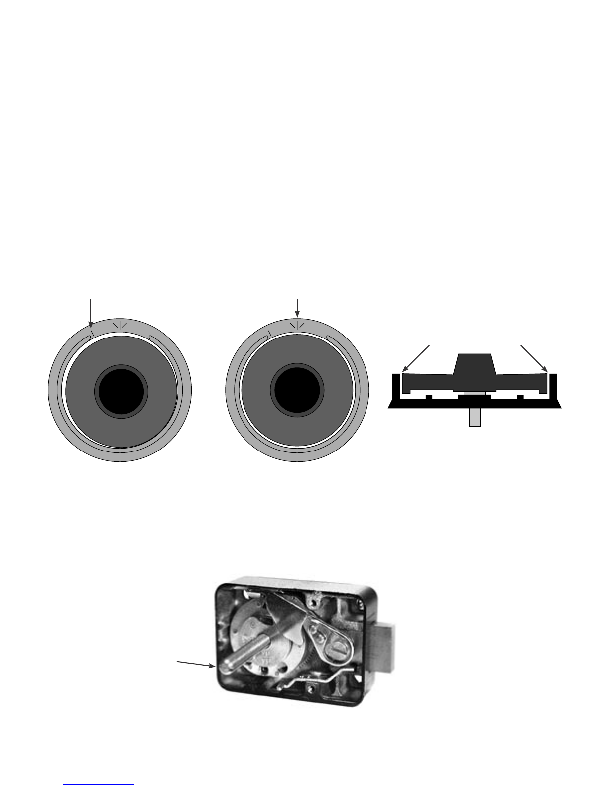
1. Remove the lock cover. Place the lock bolt in the extended position and the accelerator spring in the
loaded position (Figure 1). CAUTION: Do not remove the drive cam.
Accelerator Spring in Released Position Accelerator Spring in Loaded Position
Figure 1
MP Lock
Illustrations
Torque Adjusting Gear
Sargent & Greenleaf, Inc.
PO Box 930, Nicholasville, Kentucky 40356 USA
Phone (859) 885-9411
Phone (800) 826-7652
FAX (859) 887-2057
FAX (800) 634-4843
Copyright© 2002, Sargent & Greenleaf, Inc.
page 1
Sargent & Greenleaf S.A.
9, chemin du Croset
1024 Ecublens, Switzerland
Phone 41-21-691-9583
FAX 41-21-691-5349
Document 630-674
Revision 1.1 (7/7/03)
2. Mount the lock in place with four
1
X 20 attaching screws (provided).
⁄
4
3. Attach the dial ring by loosely installing the attaching screws to hold the dial ring in place for alignment.
The dial ring opening index should be at the 12 o’clock center position.
4. To install the dial, hold the drive cam in place with one hand and thread the dial/spindle assembly into
the cam until the dial comes to a stop against the surface of the dial ring.
Caution: When threading the dial into the cam, do not allow the cam to slide outward against the accelerator
spring. The accelerator spring can be easily damaged in this manner.
5. The alignment of the dial and ring is critical to the proper operation of the lock. Perfect alignment must
be obtained. The dial should be ush and centered with the surface of the dial ring for true centering
(Figure 2).
Figure 2
Changing Index Opening Index
Dial Edges
Flush with Ring
Misaligned Aligned
6. Measure the excess spindle that projects beyond the drive cam (Figure 3)
7. Remove the dial, cut off the excess spindle, and remove any burrs from the end. You may also nd that
the spindle threads more easily into the drive cam after cutting if the spindle end is beveled slightly.
Figure 3
Excess Spindle
page 2
8. Tighten the dial ring screws.
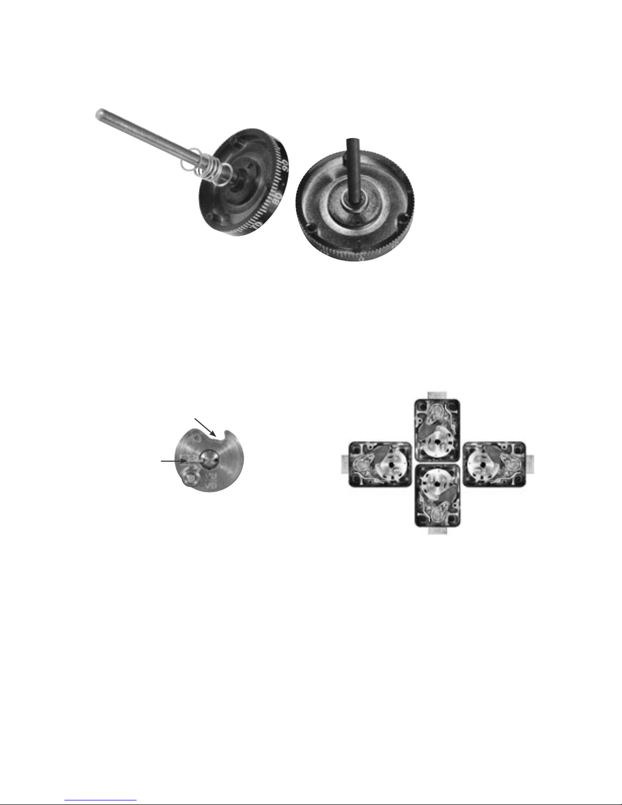
9. Place a at washer, the compression spring, and another at washer over the spindle and into the recess
at the dial hub (Figure 4).
Figure 4
10. Insert the dial into the lock, but remember that you should not allow the cam to slide outward against
the accelerator spring, possibly damaging it. Hold the drive cam in place, positioned for its gate to
receive the nose of the drop lever, and thread the dial into the cam until the dial stops.
11. Turn the dial counterclockwise until zero is aligned with the opening index of the dial ring, then turn
the dial one turn farther counterclockwise. When this is done, the proper spindle spline keyway and
drive cam spline keyway should be closely aligned (vertical-up—VU, right-hand—RH, etc.).
Figure 5
VU Mount
Gate
Spline Key
LH Mount
RH Mount
VD Mount
12. Insert the spline key with the tip toward the edge of the cam. Tap in lightly. Be very careful to avoid
striking the stainless steel roller that is attached to the top surface of the drive cam. With the spline
key inserted fully, the dial must turn freely with no rubbing or interference.
Note: Before installing the lock‘s cover, check for proper in and out travel of the dial to make sure the
accelerator spring operates correctly.
13. Turn the dial at least one complete revolution in either direction and then stop at zero. The accelerator
spring should now be in the loaded position.
14. Hold the cover in place on the lock and push the dial in at zero. Release the dial. Remove the
cover and check the position of the accelerator spring. It should be in the released position. If the
accelerator spring is not in the released position, the dial has not been backed out of the cam far
enough, and the condition must be corrected. Remove the spline key, hold the cam, and rotate the dial
one additional full turn counterclockwise. Install a new spline key and repeat steps 13 and 14.
page 3
 Loading...