

Sargent and Greenleaf 6126 Installation Instructions Manual
Installation Instructions
Model 6126 Audit Lock
Electronic Safe Lock
• Für Anweisungen auf Deutsch besuchen Sie bitte die folgende Website:
• Para obtener instrucciones en español, visite la siguiente página web:
• Pour obtenir les instructions en français, veuillez consulter le site ci-dessous:
• Per istruzioni in lingua italiana, visitare il sito web seguente:
• 如果要获取中文版的说明,请访问以下网址:
Mounting Considerations
• Sargent & Greenleaf 6100 series Motorized Electronic Combination Locks have
been designed to use the same mounting screw locations and occupy the same
space as most other S&G locks, both mechanical and electronic.
• Modifications to the lock (including lock bolt attachments) are not
recommended, and will void the your warranty.
• A minimum distance of .150" (3,8 mm) is required between the end of the lock
case containing the bolt and the closest approach of the safe’s blocking bar or
cam plate which is normally blocked by the extended lock bolt. Do not allow
the safe’s blocking bar or cam plate to depress the electronic lock’s bolt farther
than it retracts during normal motor operation. This can lead to inconsistent lock
operation.
• The 6100 series requires two 9-volt alkaline batteries (may or may not be included with your lock depending on the
specific kit ordered). We recommend fresh Duracell® batteries. Do not use old or partially drained batteries.
www.sargentandgreenleaf.com/
OPinstr.php
Attaching Screws: Use only the screws provided with the lock. Lock body mounting screws will be
either ¼-20 or M6, depending on the application. They must engage the mounting plate by at least
four full threads. Do not use lock washers or thread sealing compounds unless specifically directed to
do so in the full installation instructions.
Recommended Attaching Screw Torque: 30 to 40 inch-pounds (33.9 to 45.2 dNm) for the lock body.
No more than 15 inch-pounds (1.695 Nm) for the keypad attaching screws.
Minimum Lock Cable (Spindle) Hole Diameter: 0.312" ( 7,9 mm )
Maximum Lock Cable (Spindle) Hole Diameter: 0.406" (10,3 mm)
Lock is Designed to Move: 0.0 lbs. (0 Newtons)
Lock Bolt Maximum Free Movement: 0.352" (8,95 mm) 0.109 inch outside the edge of the lock case
Maximum Bolt End Pressure: Lock is designed to withstand at least 225 lbs. (1000 Newtons)
Maximum Bolt Side Pressure : Safe and container boltwork or locking cam designs must never apply
more than 225 lbs. (1000 Newtons) of side pressure on the lock bolt.
Mounting Environment: The lock body is designed to be mounted inside a secure container. The
container must be constructed to offer protection against physical attack directed at the lock. The
amount of protection is dependent on the desired level of security for the system as a whole. Lock protection may include barrier materials, relock devices, thermal barriers, thermal relock components, or any
combination of these. Relock device attaching screws must NOT be longer than the depth of the tapped
attaching screw hole provided in the lock case. A minimum distance of .150 inch (3,8 mm) is recommended between the end of the lock case and the closest approach of the safe’s blocking bar or cam plate
(which is normally blocked by the extended lock bolt). Maintaining this clearance will allow the lock to
deliver optimum performance. The container should be constructed to prevent access to the combination
lock without the use of tools when the container door or drawer is left open.
Code Restrictions: Personal data that can be related to a code holder, such as a birth date, street number, or phone number, should not be used in creating a lock code. Avoid codes that can be easily guessed.
Note: Every installation of this product must comply with these requirements and those in the product installation instructions to qualify for the manufacturer’s warranty and to comply with EN1300 requirements.
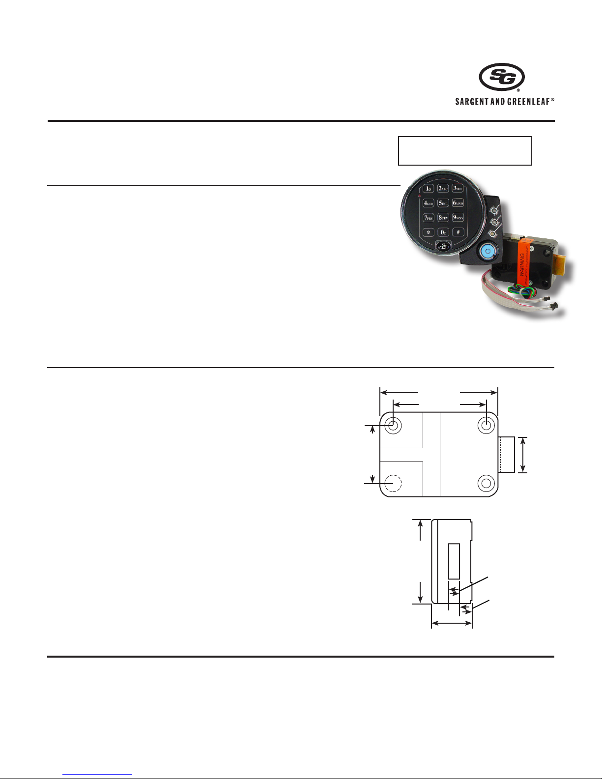
1.624" (41,2mm)
3.320" (84,3mm)
2.624" (66,6mm)
2.400" (61,0mm)
1.165" (30mm)
Bolt extension:
Locked = .461"
(11,71mm)
Unlocked = .125"
(3,18mm)
1.000" (25,4mm)
.312"
7,9mm
.281"
7,1m m
Sargent & Greenleaf, Inc.
PO Box 930
Nicholasville, KY 40340-0930
Phone: (800)-826-7652 Fax: (800)-634-4843
Phone: (859)-885-9411 Fax: (859)-887-2057
Copyright© 2012, Sargent & Greenleaf, Inc.
page 1
Sargent & Greenleaf S.A.
9, Chemin du Croset
1024 Ecublens, Switzerland
Phone: +41-21 694 34 00
Fax: +41-21 694 34 09
Document 630-820
Revised 8/28/2013
Before You Install
Your 6126 Audit Lock was most likely shipped with the keypad and keypad extension connected to the lock cables to
allow for pre-installation testing. If your lock does not have cables already connected to the keypad and keypad extension, temporarily connect them now as shown in these instructions. You should install fresh batteries in the keypad
(S&G recommends Duracell® alkaline batteries) and check the function of the lock prior to installation by pressing
10101010# and observing the lock bolt retract, then extend 6 seconds later. After this check, disconnect the cables
from the extension base and keypad by pulling on the connectors (NOT on the cables themselves). The installer should
wear a properly grounded ESD wrist strap while working with lock cables and components to avoid ESD damage.
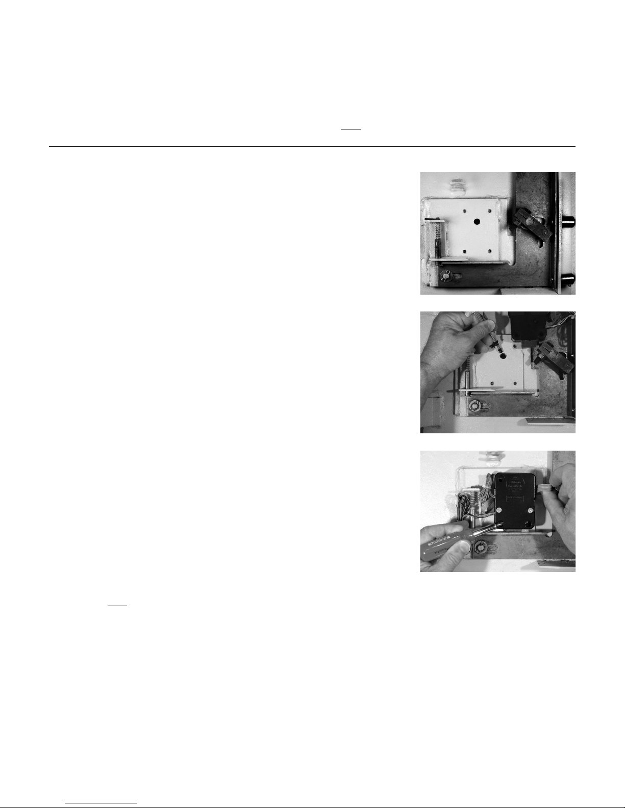
Step 1
Remove the existing lock (if present). The mounting plate should be smooth and
flat, with ¼-20 (M6) mounting screw holes. The wire channel (spindle hole) must
have a diameter of at least 0.312 inch (7,9 mm).
The 6100 series can be mounted right-hand, left-hand, vertical-up, or
vertical-down without any modifications or adjustments.
Step 2
Use a reamer or round file to remove any sharp edges from the wire channel
(spindle hole) that might damage the wire cable.
Gently pull the connectors to ease the cables through the hole. Pull 6" to 8" (15
to 20 cm) of cable to the front of the safe door. Later in the installation, excess
keypad extension cable will be pulled back inside the safe door. Make sure
cables are not crimped or stressed at any point.
Step 3
Using two of the ¼-20 (or M6) screws in the kit, loosely attach the lock body
to the safe’s mounting plate. This is just to hold it in place during cable
attachments to the keypad and keypad extension. Be very careful to avoid
crushing or crimping the cables. Note the black/red/green wire bundle. This is
for the bolt position indicator, a dry contact switch (200 VDC, 0.5 amp max.)
The black wire is common, the green wire completes a circuit to the black wire
when the lock bolt is retracted, and the red wire completes a circuit to the black
wire when the lock bolt is extended. The BPI can be used to trigger any switchactivated device.
Note the blue wire loop. This is the secure loop, a closed circuit that may be
used in applications requiring switches or other devices to signal the lock that
boltwork is thrown, the door is closed, or some other action has taken place. The
lock bolt will NOT extend if the circuit formed by the blue wire loop is open.
Both sets of wires should be bundled and placed where they will not interfere
with moving boltwork components if not used.
The lock incorporates a bolt-through cover that allows mounting with the cover in
place. Removing the cover voids the product warranty.
page 2
 Loading...