

Page 1
Installation Instructions for:
TM
Model 3006 PivotBolt
• Für Anweisungen auf Deutsh besuchen Sie bitte die folgende Website:
• Pour obtenir les instructions en français, veuillez consulter le site ci-dessous: www.sargentgreenleaf.com/OPinstr.php
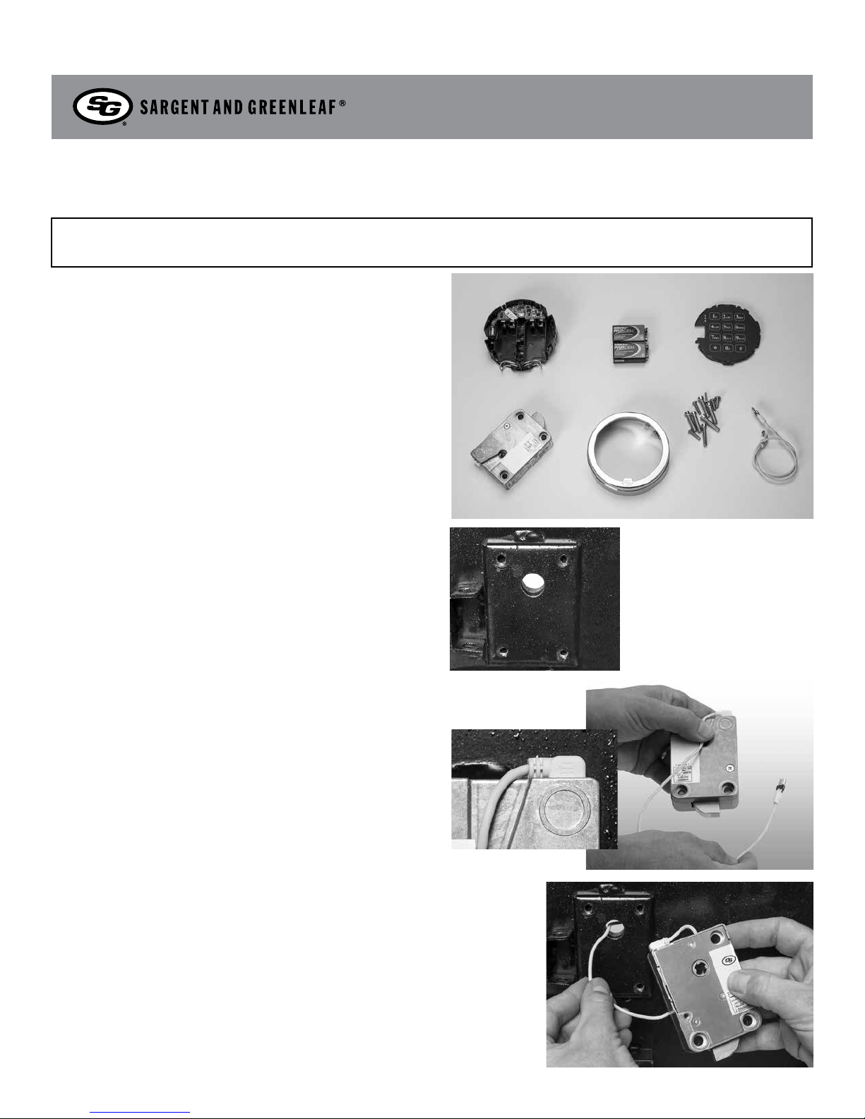
Step 1: Open the Box
Open the S&G USB Audit Lock and make sure that you have the
following parts.
• Base • (2) 9V batteries • Keypad • PivotBolt lock
• Chrome Ring • Screws • Cable
Step 2: Check Mounting Location
This lock can be mounted to storage unit of any materal as
•
long as the lock is electrically grounded and the mouting
surface is sufficiently sturdy.
• The mounting surface should be smooth and at, with either ¼ - 20 or M6
mounting screw holes.
• The wire channel (spindle hole) through the safe door must be at least
.312 inch (7,9 mm) in diameter.
• The holes should clear of sharp edges or burrs which could damage the
lock cable.
USB Audit Lock
Document # 630-889
Revision 10/02/15
Step 3: Place the Cable in the Recessed Channel
The cable runs through the opening of the case and on through the safe’s
spindle hole to the keypad.
No matter which side of the case is placed against the safe’s mounting plate,
the lock cable needs to be routed in the recessed channel in the lock’s cover.
The cable is routed around the end of the lock and through the recessed
channel, where it will make a 90 degree bend before running through the
safe’s spindle hole to the keypad.
Plug the Cable into the Lock
• The USB audit lock is a reversible, non-handed electronic safe lock.
• It is necessary to plug the provided cable into the lock. This is a connector
that will only insert one way. Make sure it is fully inserted and locked into
the lock case receptacle.
Step 5: Determine Which Direction Lock is to be Mounted
Either side of the lock case can be mounted against the safe door to
accommodate the direction of movement of the blocking bar or cam plate of
the safe’s boltwork.
Page 2
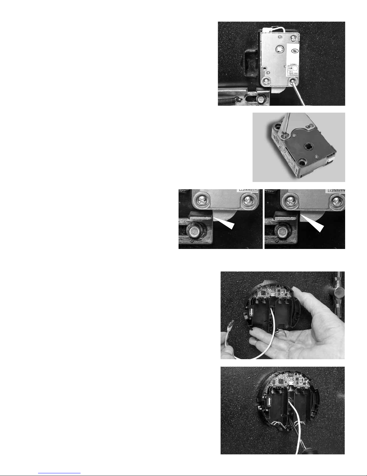
Step 5: Mount the Lock
• Insert the lock cable through the spindle hole and gently pull it from
the front of the safe as you place the lock body against the
mounting surface.
• After making sure the cable is protected within the lock’s recessed
channel, and not crimped or stressed at any point, attach the lock
body to the mounting surface, using the screws provided.
• Tighten the mounting screws to 30 to 40 inch pounds
(33.9 to 45.2dNn)
• Make sure there is a minimum clearance of o.150 inch (3.8mm)
between the end of the lock case and the blocking bar of the
safe’s boltwork.
Relocking Option
If the safe incorporates a relock device plate, it will likely attach to the
lock body as shown at right. If it attaches using the lock’s covers screw
, make sure the scres engage the lock by at least 4 threads. Substitute
longer 8-32 machine screws if necessary. It may be necessary to trim
longer screws to a proper workiing length. Relock device atttaching
screws must NOT be longer than the depth of the tapped hole provided
in the lock case.
Step 6: Check Lock Function
• The lock cannot function properly if it binds against the safe’s
boltwork. The photo on the left shows boltwork in the fully locked
position and placing pressure on the side of the lock bolt. It could
prevent the lock from opening. (INCORRECT)
• In the photo on the far right, the boltwork bind has been relieved by
removing a sm all amount of material from the right side of the blocking
bar’s bolt opening. When the boltwork is fully thrown to the locked
position, there is clearance on all sides of the lock’s bolt. This is the desired
relationship. (CORRECT)
INCORRECT CORRECT
Step 7: Attach Mounting Base
• From the outside of the safe door, bring the lock cable through the
center hole in the mounting base.
• Pulling gently on the cable, move the keypad base against the safe
door, and attach it using the two screws provided.
• Fasten the base to the safe door using either the silver colored 8-32
machine (silver color) screws or the tinted pair of M4 screws (tinted)
whichever is appropriate for the prepared holes in the safe door.
• Do not tighten beyond 15 inch-pounds (1,695 Nm).
Page 3

Step 8: Plug Cable Into the Keypad
• Plug the lock cable into connector on the PCB
• Ensure the arrow on the plug is facing up.
tep 9: Tucking Cable into Recessed Channel
S
• Place the lock cable into the recessed area.
• The excess cable should be folded and placed into the channel shown
at right. Ensure that no part of the cable extends above the wall of the
channel, since that will interfere with the keypad placement.
Step 10: Placing Keypad onto Base
Keeping the lock cable in its compartment, place the keypad onto the
•
base. The top seats into the base rst, then the bottom.
• Carefully lower the top of the keypad so that the light green area slides
between the gold pins and the black plastic tab. Take care not to bend
the six gold pins. DO NOT use excessive force to insert the keypad.
Step 11: Batteries Installation
• Open clips as shown at right and prepare to insert batteries. Once
batteries are inserted, push clip closed. The battery clip will note latch if
battery is inserted backward.
NOTE the “+” on the 9V battery (small contact) and position it to match
the “+” on the Keypad base.
Step 12: Verify Lock Function
• To open the lock, use the factory setting for PIN position 10, with PIN
Code 101010. Enter: 10 101010 # and the lock willopen. (If lock
does not open compare beep patterns heard after pressing the # key,
with reference Section 2.3 “Beep Patterns” to identify problem condition.
Step 13: Install One Way Screw
• Install and tighten the keypad security screw as shown.
Step 14: Placing Chrome Ring Over Base
• Align Chrome Ring as shown and press down over the base.
• For future access to batteries, Chrome Ring can be lifted to expose
batteries.
Page 4

STEP 15: Program Lock
• (See Operating Instructions)
IMPORTANT: Test the lock function at least three
times with the door open before closing the
safe door with S&G 3006 Pivot Bolt USB Audit Lock
3006 PivotBolt Specications
Attaching Screws: Use only the screws provided with the lock. They
must engage the mounting plate by at least four full threads. Do not use
lock washers or thread sealing compounds.
Recommended Attaching Screw Torque: 30 to 40 inchpounds (33.9 to 45.2 dNm)
Minimum Lock Cable (Spindle) Hole Diameter: 0.312 inch (7.9 mm)
Maximum Lock Cable (Spindle) Hole Diameter: 0.406 inch (10.3 mm)
Lock is Designed to Move: 0.0 lbs. (0 Newtons)
Lock Bolt Maximum Free Movement: 0.352 inch (8.95 mm)
0.109 inch outside the edge of the lock case
Maximum Bolt End Pressure: lock is designed to withstand at least 225 lbs. (1000
Newtons)
Maximum Bolt Side Pressure: safe and container boltwork or
locking cam designs must never apply more than 225 lbs. (1000 Newtons)
of side pressure on the lock bolt.
Mounting Environment: The lock body is designed to be mounted inside a secure
container. The container must be constructed to oer protection against physical
attack directed at the lock. The amount of protection is dependent on the desired level
of security for the system as a whole. Lock protection may include barrier materials,
relock devices, thermal barriers, thermal relock components, or any combination
of these. Relock device attaching screws must NOT be longer than the depth of
the tapped hole provided in the lock case. Security relevant parts of a high
security lock should not be accessible to unauthorized persons when the door of
the secure storage unit to which it is fitted is open. A minimum distance of .150
inch (3,8 mm) is recommended between the end of the lock case and the closest
approach of the safe’s blocking bar or cam plate (which is normally blocked by the
extended lock bolt). Maintaining this clearance will allow the lock to deliver optimum
performance. Code Restrictions: Personal data that can be related to a code holder,
such as a birth date, street number, or phone number, should not be used in creating a
lock code. Avoid codes that can be easily guessed (such as 1 2 3 4 5 6 or 1 1 1 1 1 1). The
lock’s factory default code must be changed to a unique, secure code when the lock is
put into operation by the end user.
Note: Every installation of this product must comply with these requirements and
those in the product installation instructions to qualify for the
manufacturer’s warranty and to comply with EN1300 requirements.
Condential
The information contained in this document is proprietary to Sargent & Greenleaf, Inc. Publication or
duplication of this copyrighted document is strictly prohibited.
S&G Audit Lock Electronic Safe Lock
Limited Warranty
Sargent & Greenleaf, Inc.
A Wholly Owned Subsidiary of Stanley Security Solutions, Inc.
PO Box 930
Nicholasville, KY 40356
Phone: (800)-826-7652 Fax: (800)-634-4843
Phone: (859)-885-9411 Fax: (859)-887-2057
Sargent & Greenleaf S.A.
9, Chemin du Croset
1024 Ecublens, Switzerland
Phone: +41-21 694 34 00
Fax: +41-21 694 34 09
 Loading...