

Page 1
User Instructions
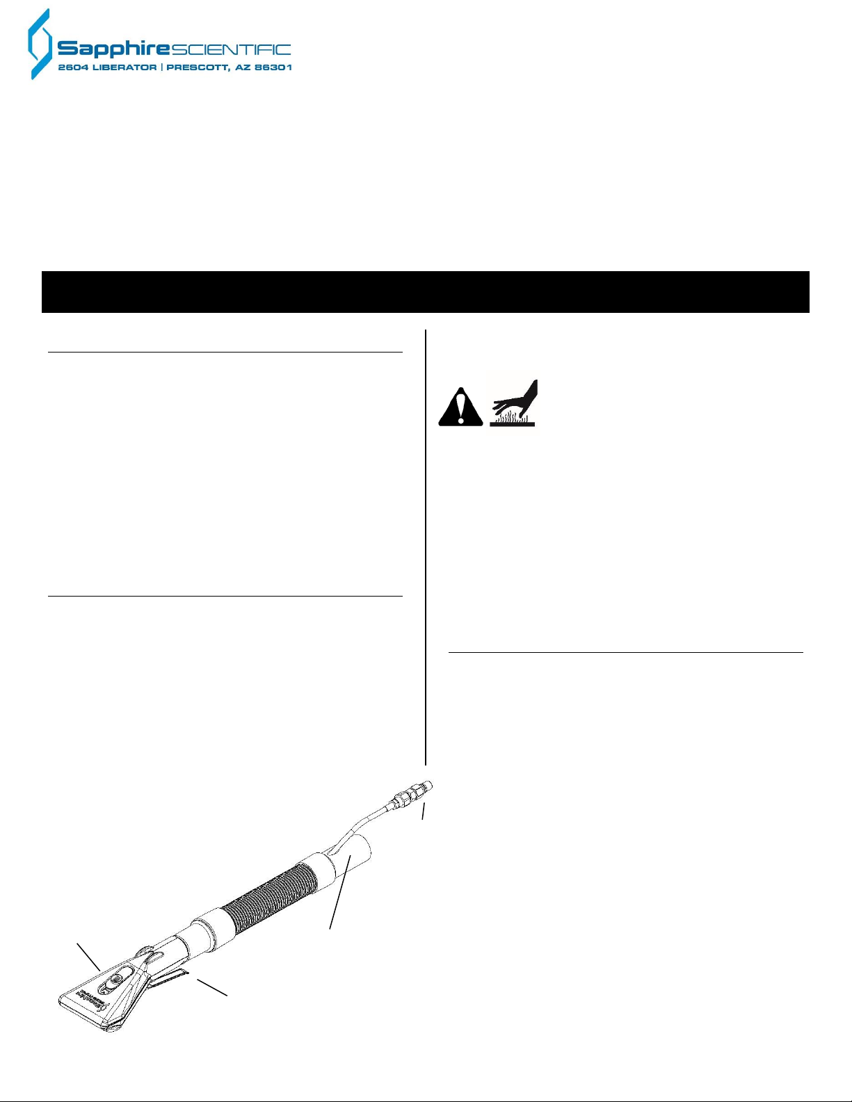
Rear vacuum hose cuff.
FIG. A: HEAD, VACUUM HOSE AND
SOLUTION LINE ASSEMBLY
Solution line
parts detail.
Vacuum
release slide
Solution trigger lever.
Upholstery Pro
Model F436-P
The Upholstery Pro cleaning tool provides deep, rapid penetration of cleaning solution and
simultaneous high volume extraction. Lightweight, easy to use, and adjustable for a wide range of
fabrics and soiling conditions, the Upholstery Pro produces cleaner, drier fabrics.
Patents: http://www.LBpatents.com
REA D A N D S A V E T H E S E I N S T R U C T I O N S
KEY FEATURES
Comfortable handle and highly flexible vacuum hose
provides relaxed balanced handling and substantially
reduces operator fatigue.
In-line solution strainer helps prevent clogging.
High pressure injector glide provides deep, even
penetration of solution into fabric surface.
Unique dual extraction slots permit full extraction in
both directions across fabric surfaces
Sliding vacuum release allows for precise vacuum
control on delicate fabrics.
Clear housing for easy monitoring of water flow, fabric
or carpet dryness, and cleaning effectiveness.
USING THE UPHOLSTERY PRO
1. Connect the rear quick-connect solution line to the
extractor solution line
2. Attach the rear hose coupling to the extractor vacuum
port.
3. Turn on extractor.
4. Squeeze the trigger lever to release the solution and
begin cleaning. The sliding trigger lock may be used
to hold the trigger valve in the open position.
quick-connect
coupling. See
Fig. D for
5. Use the vacuum release slide (Fig. A to adjust the
strength of the vacuum as needed.
WARNING: Quick-connect coupling
can become extremely hot during
use.
Tips for Use
Vacuum control. Use the vacuum release slide (Fig. A)
to control the strength of the vacuum when extracting
thin, delicate or lightweight fabrics.
For best results, use the Upholstery Pro with Legend
Brands cleaning chemicals.
For more information about cleaning with the Upholstery
Tool, visit LegendBrandsCleaning.com.
MAINTENANCE
Daily: Rinse the hand tool by running clean water
through the solution line.
Daily: Check the glide assembly (Fig. A) for steady,
even flow of solution through the injector nozzles. If any
of the injector ports appear clogged, use a small needle
to remove the obstruction, taking care not to damage the
glide. If the glide is scratched, gouged, snags on
carpets, or flows excessively, it may need to be
replaced (see “Servicing the glide,” below).
Replacement glide assemblies are available from
your distributor.
As needed: Lubricate the quick-connect
couplings (Fig. A) with a small amount of rust-
inhibiting oil such as LPS-3.
As needed: Lubricate trigger valve stem (Fig.
C) with a small amount of synthetic heavy duty
grease. To grease the stem, follow these steps.
1. Remove the trigger lever nut and bolt from the
trigger lever and remove lever.
2. Unscrew stem retention nut and lift out stem
07-02087B F436-P 1 Sapphire Scientific
assembly. Apply a small amount of grease to the
stem.
Page 2
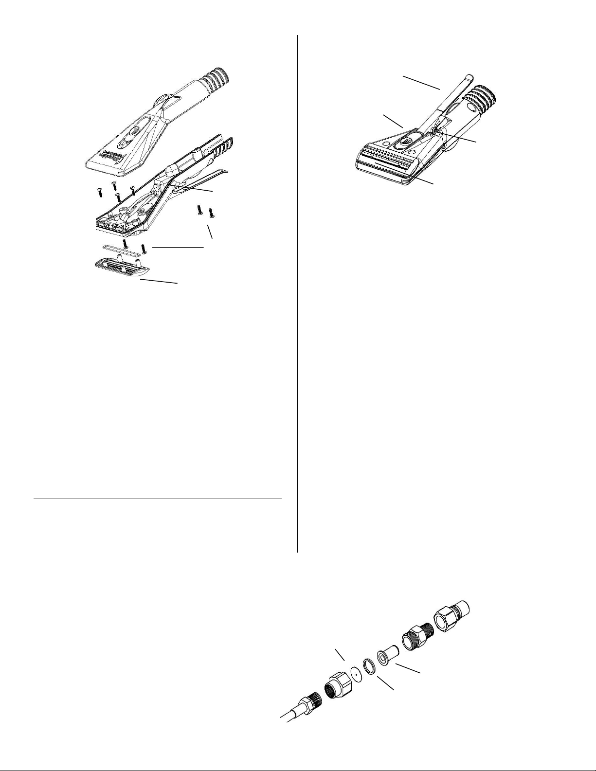
FIG. C: HEAD (BOTTOM VIEW)
Trigger lever
Glide
Trigger lever lock
Trigger lever
nut and bolt
Hex nut. Loosen here
Nylon washer
(03-01652)
Orifice
(03-01903)
Rear quickconnect coupling
Inline strainer
(03-01649)
FIG. D: SOLUTION LINE COUPLING ASSEMBLY
FIG. B: HEAD ASSEMBLY
Cover screws
(×4)
Glide and O-ring seal
(S13-01705)
Glide
screws (×4)
Trigger valve body
(13-01690)
Upper cover
Lower cover
(Inside
cover.)
1. Replace stem assembly and retighten retention nut.
Reattach trigger lever.
As needed: Clean the inline strainer (Fig. D) when
solution flow is visibly reduced. To clean the filter, loosen
the strainer assembly nut, and remove the strainer and
strainer washer. Rinse these items in clean water and
reassemble the strainer. It is not usually necessary to
replace the inline filter element. Be sure to include the
nylon washer when reassembling, and take care not to
over-tighten the strainer assembly nut.
To maintain appearance, wipe exterior surfaces with a
damp cloth.
SERVICING
The Upholstery Pro is designed to allow easy in-the-field
service to the glide and the trigger valve with basic hand
tools in just a few minutes. If replacement becomes
necessary, rebuild kits and replacement parts are
available from your Sapphire distributor or
from Sapphire Scientific at 800-932-3030.
Replacing the glide
Have on hand a Glide and O-ring
replacement kit (part no. S13-01705).
1. Remove the four cover screws (Fig. B)
and lift off the cover.
2. Remove the four glide screws (Fig. B)
and remove the glide and the O-ring seal.
Discard.
3. Install new O-ring into sealing edge of
new glide. Put new glide into head. Make
sure that the O-ring is in place.
4. Replace glide screws and tighten; then replace
cover and tighten with cover screws.
Servicing the trigger valve
If the trigger leaks or no longer releases sufficient
solution and you have determined that the glide is not
plugged or damaged (see “Check Glide Assembly,” p. 1)
the trigger may need service. Two repair options are
available.
Option A: Rebuild the trigger valve.
A stem replacement kit (part no. 48-064) is available
from your Sapphire distributor. The parts included in this
kit are shown in Fig. E.
1. Remove the nut and bolt from the trigger lever and
remove the lever.
2. Unscrew stem retention nut and lift out stem
assembly.
3. Install the stem assembly and retighten the stem
retention nut.
4. Replace cover and reinstall trigger lever. Use the
new lock nut provided (Fig. E).
Option B: Replace the trigger valve assembly
A replacement trigger valve assembly (part no. 13-
01690) is available from your Sapphire distributor.
1. Remove the four cover screws (Fig. B) and lift off the
cover.
2. Depress the hose release ring on the solution outlet
tube and pull out the tube. Avoid kinking the tube.
to access strainer.
07-02087B F436-P 2 Sapphire Scientific
Page 3
Description
Drawing
reference
Replacement
part no.
Trigger and valve body
Fig. B
13-01690
Glide and O-ring seal
Fig. B
S13-01705
Strainer
Fig. D
03-01649
Orifice
Fig. D
03-01903
Nylon washer
Fig. D
03-01652
Model
Sapphire Scientific Upholstery Pro F436-P
Part no. 67-019 67-019-P
Dimensions
Head: 4 in. extraction width
Hose assembly: 10 ft.
Construction
Head: High performance copolyester.
Glide: Engineering thermoplastic
Hose assembly: High-flex vacuum hose
Fittings: Brass with high-temp seals
Specifications are subject to change without notice. Some values
may be approximate.
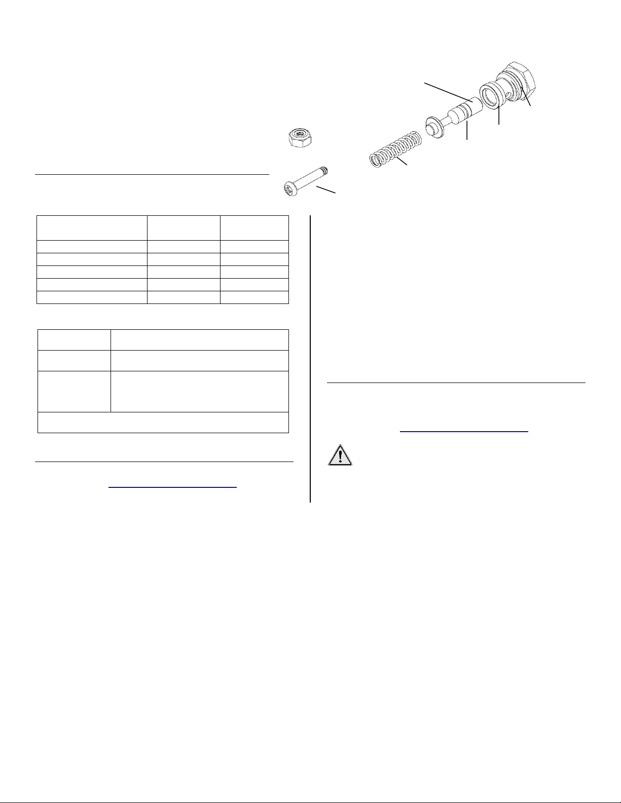
1. Stem retention nut
FIG. E: STEM REPLACEMENT KIT (48-064)
2. Stem.
apply grease
6. O-ring seal
5. Teflon seal
7. Extractor spring
3. Trigger lever lock nut
8. Shoulder screw
4. O-ring seal
3. Remove the solution outlet tube fitting from the
valve body.
4. Disconnect the solution inlet hose assembly
from the valve body.
5. Valve body and trigger will now drop free.
6. Insert new trigger valve assembly and reinstall
solution outlet tube and solution inlet hose
assembly.
7. Replace cover.
REPLACEMENT PARTS
The following replacement parts are available from
your Sapphire Scientific distributor:
SPECIFICATIONS
Periodically
Warranty registration
Visit LegendBrandsCleaning.com to register your
purchase. Registration allows us to better assist you with
using, maintaining or servicing your equipment, as well
as to contact you in case we have important safety
information concerning your Sapphire Scientific product.
If you determine service is required, have your
equipment model, serial number and original proof of
purchase available and call your distributor for
assistance with obtaining a return material authorization
(RMA).
WARRANTY
Warranty information is available from your Sapphire
Distributor or at LegendBrandsCleaning.com.
CONTACT
Sapphire Scientific
2604 Liberator
Prescott, AZ 86301
800-932-3030 LegendBrandsCleaning.com
WARNING: This product may expose you to
chemicals, including lead and phthalates, known
to the State of California to cause cancer, birth defects,
or other reproductive harm. For more information, go to
P65Warnings.ca.gov
07-02087B F436-P 3 Sapphire Scientific
Page 4

Boquilla de manguera
de aspiración trasera
FIG. A: CABEZAL, MANGUERA DE
TUBO DE SOLUCIÓN
Acoplamiento
detalle.
Regulador de
aspiración
Palanca del gatillo de
Instrucciones de uso
Upholstery Pro
Modelo F436-P
La Upholstery Pro es una herramienta de limpieza que garantiza una penetración rápida y profunda de la solución limpiadora
y una extracción de grandes cantidades de suciedad simultáneamente. La Upholstery Pro pesa poco, es fácil de usar y se
adapta a una amplia variedad de telas y distintos niveles de suciedad para así dejar las telas más limpias y secas.
Patentes: http://www.LBpatents.com
LEA Y GUARDE ESTAS INSTRUCCIONES
CARACTERÍSTICAS PRINCIPALES
Mango cómodo y manguera aspiradora muy flexible
que permite un manejo equilibrado y distendido del
aparato, y disminuye el cansancio del operador
considerablemente.
Filtro de solución interno que ayuda a prevenir
obstrucciones.
Deslizante inyector de alta presión que garantiza una
penetración profunda y pareja de la solución en la
superficie de la tela.
Ranuras de extracción duales que permiten la
extracción total en ambas direcciones a lo largo de la
superficie de tela.
Disparador de aspiración regulable que permite tener
un control preciso de la potencia de aspiración en
telas delicadas.
Unidad principal transparente que facilita el control del
flujo del agua, de la sequedad de la tela o alfombra y
de la eficacia de la limpieza.
USO DE LA UPHOLSTERY PRO
1. Conecte el tubo de solución trasero de fijación
rápida al tubo de solución del extractor.
2. Junte el acoplamiento de la manguera trasera con el
puerto de aspiración del extractor.
3. Encienda el extractor.
4. Apriete la palanca del gatillo para expulsar la solución
y comenzar a limpiar. La traba del gatillo deslizable
se puede utilizar para mantener la válvula con gatillo
abierta.
5. Utilice el regulador de disparo de aspiración
(Fig. A) para ajustar la potencia de la aspiradora
según lo necesite.
ADVERTENCIA: El acoplamiento de
fijación rápida se puede calentar
mucho mientras se utiliza el aparato.
Consejos de uso
Control de la aspiradora. Utilice el regulador de
disparo de aspiración (Fig. A) para controlar la potencia
de la aspiradora cuando se utilice sobre telas finas,
delicadas y de poco peso.
Para optimizar los resultados, utilice la Upholstery Pro
con productos químicos de limpieza de Legend Brands.
Si desea obtener más información sobre el modo de uso
de la Upholstery, visite el sitio
LegendBrandsCleaning.com.
MANTENIMIENTO
A diario: Para enjuagar la herramienta manual, deje
correr agua limpia a través del tubo de solución.
A diario: Verifique el ensamblaje del
ABSORCIÓN Y ENSAMBLAJE DEL
del tubo de
solución de
fijación
rápida. Vaya
disparo de
07-02087B F436-P 4 Sapphire Scientific
a la Fig. D
para ver las
partes en
deslizante (Fig. A) para que el flujo de solución
expulsado por las boquillas del inyector sea
parejo y regular. Si alguno de los puertos del
inyector se obstruye, utilice una aguja pequeña
para remover la obstrucción, sin dañar el
deslizante. Si el deslizante se raya, se pica, se
engancha en las alfombras o expulsa la solución
Page 5

FIG. C: CABEZAL (VISTA INFERIOR)
Palanca del gatillo
Barra deslizante
Traba de la palanca del
gatillo
Tornillo y tuerca de la
Tuerca de cabeza
para acceder al filtro.
Arandela de nailon
(03-01652)
Orificio
(03-01903)
Acoplamiento
rápida
Filtro interno
(03-01649)
FIG. D: ENSAMBLAJE Y ACOPLAMIENTO DEL
TUBO DE SOLUCIÓN
FIG. B: ENSAMBLAJE DEL CABEZAL
Tornillos de la
cubierta (4)
Barra deslizante y
01705)
Tornillos del
Cuerpo de la
Cubierta
superior
Cubierta
inferior
palanca del gatillo
deslizante
(4)
(Cubierta
interna)
anillo obturador (S13-
válvula con gatillo
(13-01690)
excesivamente, es posible que necesite reemplazarlo
(lea la próxima sección “Sustitución del deslizante”). Los
repuestos del ensamblaje del deslizante se encuentran
a su disposición a través de su distribuidor.
Cuando sea necesario: Lubrique los acoplamientos
de fijación rápida (Fig. A) con un poco de aceite
inhibidor de oxidación como el LPS-3.
Cuando sea necesario: Lubrique el vástago de la
válvula con gatillo (Fig. C) con una pequeña cantidad
de grasa pesada sintética. Para engrasar el vástago,
siga estos pasos:
1. Retire la tuerca y el tornillo de la palanca del
gatillo y luego retire la palanca.
2. Desenrosque la tuerca de retención del vástago
y retírelo. Coloque una pequeña cantidad de
grasa en el vástago.
3. Vuelva a colocar el ensamblaje del vástago y
ajuste la tuerca de retención. Coloque la
palanca del gatillo nuevamente.
Cuando sea necesario: Limpie el filtro
interno (Fig. D) cuando vea que se redujo el
flujo de solución. Para limpiar el filtro,
desajuste la tuerca del ensamblaje del filtro y
remueva el filtro y la arandela del filtro.
Enjuague estos elementos con agua limpia y
vuelva a armar el filtro. En general, no es
necesario sustituir el filtro interno. Asegúrese
de colocar la arandela de nailon cuando lo
vuelva a armar y trate de no ajustar
excesivamente la tuerca del ensamblaje del
filtro.
Para mantener el aspecto del exterior del
aparato, límpielo con un paño húmedo.
SERVICIOS PARA EL MANTENIMIENTO
La Upholstery Pro está diseñada para facilitar el
mantenimiento del deslizante y la válvula con gatillo con
las herramientas manuales básicas dentro del área de
trabajo y en solo unos minutos. Si necesita sustituir
alguna pieza, los equipos de rearmado y las piezas de
repuesto se encuentran a su disposición a través de su
distribuidor de Sapphire o llamando al número de
teléfono de Sapphire Scientific: 800-932-3030.
Sustitución de la barra deslizante
Tenga a mano un equipo de sustitución de la barra
deslizante y el anillo obturador. (Pieza n.º S13-01705).
1. Retire los cuatro tornillos de la cubierta (Fig. B) y
separe la cubierta.
2. Retire los cuatro tornillos del deslizante (Fig. B) y
retire la barra deslizante y el anillo sellador.
Deséchelos.
3. Instale el nuevo anillo en el extremo de cierre de la
nueva barra deslizante. Coloque la nueva barra
deslizante en el cabezal. Asegúrese de que el
nuevo anillo obturador esté en su lugar.
4. Vuelva a colocar los tornillos del deslizante y ajuste;
luego, coloque la cubierta y ajuste con los tornillos
de la cubierta.
trasero de fijación
hexagonal. Afloje aquí
07-02087B F436-P 5 Sapphire Scientific
Page 6

Descripción
Dibujo de
referencia
Número de
pieza de
repuesto
Cuerpo de válvula con
gatillo
Fig. B
13-01690
Barra deslizante y anillo
obturador
Fig. B
S13-01705
Filtro
Fig. D
03-01649
Orificio
Fig. D
03-01903
Arandela de nailon
Fig. D
03-01652
Modelo
Sapphire Scientific Upholstery Pro F436-P
Pieza n.º 67-019 67-019-P
Dimensiones
Cabezal: 4 pulgadas de ancho de extracción
Ensamblaje de manguera: 10 pies
Material de
construcción
Cabezal: resina de copolyester.
Deslizante: termoplástico de ingeniería
Ensamblaje de manguera: manguera de
absorción muy flexible
Sujetador: chapa con selladores resistentes a
altas temperaturas
Las especificaciones del producto están sujetas a cambios sin
aviso previo. Algunos valores pueden ser aproximados.
1. Tuerca de
retención del vástago
FIG. E: EQUIPO DE SUSTITUCIÓN DEL VÁSTAGO (48-064)
2. Vástago.
6. Anillo sellador
5. Anillo sellador de
teflón
7. Resorte del extractor
3. Tuerca de la
palanca del gatillo
8. Tornillo sellador
4. Anillo
sellador
Servicio de mantenimiento de la válvula con gatillo
Si usted ha determinado que el deslizante no está
obstruido o dañado (vaya a la sección “Verifique el
ensamblaje del deslizante”) y el gatillo pierde o ya no
expulsa suficiente solución, puede que el gatillo necesite
servicio. Hay dos opciones disponibles para la
reparación:
Opción A: Vuelva a armar la válvula con gatillo.
Un equipo de repuesto del vástago (pieza n.º 48-064) se
encuentra a su disposición a través de su distribuidor de
Sapphire. Las piezas incluidas en este equipo son las
que se pueden ver en la Fig. E.
1. Retire la tuerca y el tornillo de la palanca del gatillo y
retire la palanca.
2. Desenrosque la tuerca de retención y desarme el
ensamblaje del vástago.
3. Arme el ensamblaje del vástago y vuelva a ajustar la
tuerca de retención.
4. Vuelva a colocar la cubierta y rearme la palanca del
gatillo. Utilice la nueva tuerca de traba que se le
suministró (Fig. E).
Opción B: Sustituya el ensamblaje de la válvula con
gatillo.
Un repuesto del ensamblaje de la válvula con gatillo
(pieza n.º 13-01690) se encuentra a su disposición a
través de su distribuidor de Sapphire.
1. Retire los cuatro tornillos de la cubierta (Fig. B) y
luego retire la cubierta.
2. Presione el anillo de disparo de la manguera sobre
la salida del tubo de solución y extraiga el tubo.
Evite retorcer el tubo.
3. Retire el sujetador de la salida del tubo de solución
que se encuentra dentro del cuerpo de la válvula.
4. Desconecte el ensamblaje de la manguera de
entrada de solución del cuerpo de la válvula.
5. El gatillo y el cuerpo de la válvula ahora se soltarán.
6. Inserte el ensamblaje de la válvula con gatillo nuevo
y reinstale la salida del tubo de solución y el
ensamblaje de la manguera de entrada.
7. Vuelva a colocar la cubierta.
PIEZAS DE REPUESTO
Las siguientes piezas están a su disposición a través de
su distribuidor de Sapphire Scientific:
ESPECIFICACIONES DEL PRODUCTO
GARANTÍA
La información de la garantía se encuentra a su
disposición a través de su distribuidor de Sapphire o en
el sitio web LegendBrandsCleaning.com.
Registro de garantía
Visite LegendBrandsCleaning.com para registrar su
compra. El registro nos permite brindarle una mejor
asistencia para el uso, mantenimiento y servicio de su
equipo, y contactarlo en caso de que tengamos
información de seguridad importante con respecto a su
producto Sapphire Scientific. Si se requiere servicio,
tenga a su disposición el modelo de su equipo, el
número de serie y el comprobante de compra original, y
llame a su distribuidor para que lo ayude a obtener una
autorización para la devolución del material (Return
Material Authorization, RMA).
Coloque grasa
traba de la
07-02087B F436-P 6 Sapphire Scientific
periódicamente.
CONTACTO
Sapphire Scientific
2604 Liberator
Prescott, AZ 86301
800-932-3030 LegendBrandsCleaning.com
ADVERTENCIA:
Este producto puede exponerlo a usted a
sustancias químicas como el plomo y los ftalatos
que, según el estado de California, son causantes
de cáncer, defectos en el nacimiento y otros daños
reproductivos. Para obtener más información, visite
P65Warnings.ca.gov.
Page 7

Manchon du tuyau
d’aspiration arrière
Figure A : TÊTE, TUYAU D’ASPIRATION
ET ASSEMBLAGE DE LA CONDUITE DE
SOLUTION
Raccord de
Figure D.
Glissière de réglage
de l’aspiration
Levier de déclenchement de
la solution
Instructions d’utilisation
Upholstery Pro
Modèle : F436-P
L’outil de nettoyage Upholstery Pro permet une pénétration profonde et rapide de la solution de
nettoyage et une extraction simultanée d’un volume élevé. Léger, facile à utiliser et réglable pour une
large gamme de tissus et de conditions de saleté, l’appareil Upholstery Pro permet d’obtenir des tissus
plus propres et plus secs.
Brevets : http://www.LBpatents.com
LIRE ET CONSERVER CES INSTRUCTIONS
CARACTÉRISTIQUES PRINCIPALES
La poignée confortable et le tuyau d’aspiration très
souple permettent une manipulation équilibrée et aisée
et une réduction importante de la fatigue de
l’utilisateur.
La crépine pour la solution aide à empêcher les
obturations.
Le patin à injecteur à haute pression permet une
pénétration rapide et homogène de la solution dans la
surface du tissu.
Deux fentes d’extraction uniques permettent une
extraction complète, dans les deux directions, à
travers la surface des tissus.
La glissière de réglage de l’aspiration permet un
contrôle d’aspiration précis pour les tissus délicats.
Boîtier transparent permettant une surveillance aisée
du débit d’eau, de l’assèchement du tissu ou du tapis
et de l’efficacité du nettoyage.
UTILISATION DE l’UPHOLSTERY PRO
1. Brancher la conduite de solution à connexion rapide
arrière à la conduite de solution de l’extracteur.
2. Relier le raccord de tuyau arrière à la sortie
d’aspiration de l’extracteur.
3. Mettre l’extracteur en marche.
4. Serrer le levier de déclenchement pour libérer la
solution et commencer le nettoyage. Le verrou de
déclenchement à glissière peut être utilisé pour
garder la vanne de déclenchement en position
ouverte.
5. Utiliser la glissière de réglage de l’aspiration
(Figure A) pour ajuster la puissance d’aspiration au
besoin.
ATTENTION : Le raccord de
connexion rapide peut devenir très
chaud lors de l’utilisation.
Conseils d’utilisation
Contrôle de l’aspiration. Utiliser la glissière de réglage
de l’aspiration (Figure A) pour contrôler la puissance de
l’aspiration lors de l’extraction sur des tissus fins,
délicats ou légers.
Pour obtenir de meilleurs résultats, utiliser l’appareil
Upholstery Pro avec des produits de nettoyage
Legend Brands.
Pour plus d’information sur le nettoyage à l’aide
connexion rapide
pour la conduite
de solution. Voir
des détails à la
de l’outil Upholstery, visiter
LegendBrandsCleaning.com.
MAINTENANCE
Quotidiennement : Rincer l’outil à main en
faisant couler de l’eau à travers la conduite de
solution.
Quotidiennement : Vérifier l’assemblage du
patin (Figure A) pour obtenir un débit constant et
stable de solution à travers les buses de
l’injecteur. Si toute sortie de l’injecteur semble
bouchée, utiliser une petite aiguille pour retirer
07-02087B F436-P 7 Sapphire Scientific
Page 8

Écrou hexagonal, le
à la crépine.
Rondelle en
(03-01652)
Orifice
(03-01903)
Raccord de
connexion rapide
Crépine interne
(03-01649)
FIG. D: SOLUTION LINE COUPLING ASSEMBLY
Figure B : ASSEMBLAGE DE LA TÊTE
Vis du
couvercle (×4)
Patin et joint torique
(S13-01705)
Vis du patin
du couvercle)
Corps de la vanne
(13-01690)
Couvercle
supérieur
Couvercle
inférieur
1. Écrou de rétention de la tige
Figure E : ENSEMBLE DE REMPLACEMENT
DE TIGE (48-064)
2. Tige. Appliquer
graisse ici.
6. Joint torique
5. Joint en téflon
7. Ressort de l’extracteur
3. Écrou de verrouillage du
levier de déclenchement
8. Vis à épaulement
4. Joint torique
(×4)
(à l’intérieur
l’obstruction, prendre soin de ne pas endommager le
patin. Si le patin est rayé, entaillé, s’accroche sur du
tapis, ou coule excessivement, il faut peut-être le
remplacer (voir « Entretien du patin », ci-après).
Des ensembles de remplacement du patin sont
disponibles auprès de votre distributeur.
de commande
Pour une belle apparence, essuyer les surfaces
externes avec un chiffon humide.
ENTRETIEN
L’appareil Upholstery Pro est conçu pour permettre un
entretien facile sur le terrain du patin et de la vanne de
déclenchement avec des outils à main de base, en
quelques minutes. Si le remplacement devient
nécessaire, des ensembles de réparation et des pièces
de rechange sont disponibles auprès de votre
distributeur Sapphire ou de Sapphire Scientific au
(800)932-3030.
Remplacement du patin
Se munir d’un ensemble de remplacement de patin et de
joint torique (no de pièce S13-01705).
1. Retirer les quatre vis du couvercle (Figure B) et
soulever le couvercle.
2. Retirer les quatre vis du patin (Figure B) et retirer le
patin et le joint torique. Les jeter.
3. Installer un nouveau joint torique dans le logement
d’étanchéité du nouveau patin. Placer le nouveau
patin dans la tête. S’assurer que le joint torique est
bien en place.
4. Replacer les vis du patin et les serrer; puis, replacer
le couvercle et le serrer à l’aide des vis du
couvercle.
Au besoin : Lubrifier les raccords de
connexion rapide (Figure A) avec une petite
quantité d’huile antirouille comme de la LPS-3.
Au besoin : Lubrifier la tige de la vanne de
déclenchement (Figure C) avec une petite
quantité de graisse synthétique longue durée.
Pour graisser la tige, suivre les étapes cidessous :
1. Retirer l’écrou et le boulon du levier de
déclenchement et retirer le levier.
2. Dévisser l’écrou de rétention de la tige et
soulever l’ensemble de la tige. Déposer une
petite quantité de graisse sur la tige.
3. Remplacer l’ensemble de la tige et resserrer
l’écrou de rétention. Rattacher le levier de
déclenchement.
Au besoin : Nettoyer la crépine interne (Figure
D) lorsque le débit de solution est visiblement
réduit. Pour nettoyer le filtre, desserrer l’écrou de
l’ensemble de la crépine, et retirer la crépine ainsi
que sa rondelle. Rincer ces éléments dans de l’eau
propre et réinstaller la crépine. Il n’est
généralement pas nécessaire de remplacer
l’élément filtrant interne. Ne pas oublier d’inclure la
rondelle en nylon lors du remontage, et de
s’assurer de ne pas trop serrer l’écrou de
l’ensemble de la crépine.
desserrer pour accéder
nylon
régulièrement de la
07-02087B F436-P 8 Sapphire Scientific
Page 9

Description
Illustration de
référence
No de la pièce
de rechange
Déclencheur et corps de vanne
Figure B
13-01690
Patin et joint torique
Figure B
S13-01705
Crépine
Figure D
03-01649
Orifice
Figure D
03-01903
Rondelle en nylon
Figure D
03-01652
Modèle
Sapphire Scientific Upholstery Pro F436-P
No de pièce : 67-019 67-019-P
Dimensions
Tête : largeur d’extraction de 4 po
Assemblage du tuyau : 10 pi
Construction
Tête : De copolyster haute performance.
Patin : Thermoplastique d’ingénierie
Assemblage du tuyau : Tuyau d’aspiration
extrêmement flexible
Raccords : Laiton avec joints haute température
Ces spécifications peuvent être modifiées sans préavis. Certaines
valeurs peuvent être approximatives.
FIG. C: TÊTE (VUE DU DESSOUS)
Levier de
déclenchement
Patin
Verrou du levier de
déclenchement
Écrou et
de déclenche
Entretien de la vanne de déclenchement
Si le déclencheur fuit ou qu’il ne libère pas suffisamment
de solution et que vous avez déterminé que le patin
n’est pas obturé, ni endommagé (voir « Vérifier
l’assemblage du patin »), le déclencheur doit peut-être
être réparé. Deux options sont disponibles.
Option A : Réparer la vanne de déclenchement.
Un ensemble de remplacement de tige (no de pièce 48-
064) est disponible auprès de votre distributeur
Sapphire. Les pièces composant cet ensemble sont
illustrées à la Figure E.
1. Retirer l’écrou et le boulon du levier de
déclenchement et retirer le levier.
2. Dévisser l’écrou de rétention de la tige et soulever
l’ensemble de la tige.
3. Installer l’ensemble de la tige et resserrer l’écrou de
rétention de la tige.
4. Replacer le couvercle et rattacher le levier de
déclenchement. Utiliser le nouvel écrou de
verrouillage fourni (Figure E).
Option B : Remplacer l’ensemble de vanne de
déclenchement
Un ensemble de remplacement de vanne de
déclenchement (no de pièce 13-01690) est disponible
auprès de votre distributeur Sapphire.
1. Retirer les quatre vis du couvercle (Figure B) et
soulever le couvercle.
2. Appuyer sur l’anneau de libération du tuyau sur le
tube de sortie de la solution et tirer sur le tube pour
le retirer. Éviter d’entortiller le tube.
3. Retirer le raccord du tube de sortie de la solution du
corps de la vanne.
4. Débrancher l’ensemble du tuyau d’arrivée de la
solution du corps de la vanne.
5. Le corps de la vanne et le déclencheur peuvent
maintenant être retirés librement.
6. Insérer le nouvel ensemble de vanne de
déclenchement et rebrancher le tube de sortie de la
solution ainsi que l’ensemble du tuyau d’arrivée de
la solution.
7. Replacer le couvercle.
PIÈCES DE RECHANGE
Les pièces de rechange suivantes sont disponibles
auprès de votre distributeur Sapphire Scientific :
07-02087B F436-P 9 Sapphire Scientific
boulon du
levier
SPÉCIFICATIONS
GARANTIE
Des renseignements concernant la garantie sont
disponibles auprès de votre distributeur Sapphire ou sur
le site : LegendBrandsCleaning.com.
Enregistrement de la garantie
Visiter LegendBrandsCleaning.com pour enregistrer
votre achat. L’enregistrement nous permet de mieux
vous aider pour l’utilisation, l’entretien ou la réparation
de votre équipement, ainsi que pour communiquer avec
vous en cas de consignes de sécurité importantes
concernant votre produit Sapphire Scientific. Si vous
déterminez que des réparations sont nécessaires, ayez
en main le modèle, le numéro de série et la preuve
d’achat originale de votre équipement, et appelez votre
distributeur afin d’obtenir une autorisation de retour de
matériel (ARM).
CONTACT
Sapphire Scientific
2604 Liberator
Prescott, AZ 86301
(800) 932-3030 LegendBrandsCleaning.com
ATTENTION : Cet appareil peut vous exposer à
des produits chimiques, y compris du plomb et
des phtalates, qui selon l’État de Californie peuvent
causer des cancers, des malformations congénitales ou
d’autres anomalies de reproduction. Pour de plus
amples renseignements, visiter : P65Warnings.ca.gov
 Loading...