

Sapphire Audio Pure Platinum H67,Pure Platinum H61 User Manual

User’s Manual
Sapphire Pure Platinum H67
Sapphire Pure Platinum H61
Intel H67/ H61 LGA1155 Mainboard
TRADEMARK
All products and company names are trademarks or registered
trademarks of their respective holders.
These specifications are subject to change without notice.
Manual Revision 1.1
November 03, 2011

~ ii ~
Federal Communications Commission (FCC) Statement
This device has been tested and found to comply with the limits for a Class B
digital device, pursuant to Part 15 of FCC Rules. These limits are designed to
provide reasonable protection against harmful interference in a residential
installation. This equipment generates, uses and can radiate radio frequency
energy and, if not installed and used in accordance with instructions contained
in this manual, may cause harmful interference to radio and television
communications. However, there is no guarantee that interference will not occur
in a particular installation.
If this product does cause harmful interference to radio or television reception,
which can be determined by turning the equipment off and on, the user is
encouraged to try to correct the interference by one or more of the following
measures:
Reorient or relocate the receiving antenna.
Increase the separation between the equipment and receiver.
Connect the product into an outlet on a circuit different from that to which
the receiver is connected.
Consult the dealer or an experienced radio/TV technician for help.
Í
Note1:
Connecting this device to peripheral devices that do not comply with Class
B requirements, or using an unshielded peripheral data cable, could also
result in harmful interference to radio or television reception
Note2: The user is cautioned that any changes or modifications not expressly
approved by the party responsible for compliance could void the user’s
authority to operate this product.
Note3: To ensure that the use of this product does not contribute to
interference, it is necessary to use shielded I/O cables
CE: Radiation of EN 55022 & Immunity of EN 55024
Waste Electrical and Electronic Equipment (WEEE) Statement
To protect the global environment, this product must be sent to separate collection
facilities for recovery and recycling.
DISPOSAL
Do not dispose of this product as unsorted municipal waste. Collect such
waste separately for special treatment.

~ iii ~
Table of Contents
Chapter 1 Introduction ................................................................ 1
1-1 Mainboard Specifications ........................................................ 1
1-2 Package Contents ................................................................ 4
1-3 Mainboard Layout ................................................................. 5
Chapter 2 Installation ................................................................ 10
2-1 Before You Begin ................................................................ 10
2-2 Installing the I/O Shield ....................................................... 10
2-3 Securing to the Chassis ...................................................... 10
2-4 Installing the CPU and Fan Heatsink .................................. 11
2-5 Installing System Memory ................................................... 11
Memory configurations ........................................................ 12
Memory Installation ............................................................. 12
2-6 Installing Expansion Cards ................................................. 13
PCI-E Slot ........................................................................... 13
Mini PCI-E Slot .................................................................... 13
2-7 Connecting Cables ............................................................. 14
Connecting Power Supply Cables ....................................... 14
Connecting Serial ATA (SATA) Cables ................................. 15
Connecting to the Internal Headers and Connectors .......... 16
Front Panel Header ....................................................... 16
USB2.0 Headers ............................................................ 17
CFPA Header ................................................................. 17
Speaker Header ............................................................. 17
Fan Headers .................................................................. 18
2-8 Jumper Settings .................................................................. 19
Chapter 3 Configuring the BIOS ............................................... 20
3-1 Select Boot Device ............................................................. 20
3-2 Enter BIOS Setup ............................................................... 20
3-3 Main Menu .......................................................................... 22
3-4 Performance Menu ............................................................. 23

~ iv ~
CPU/GPU Configuration ...................................................... 23
Memory Configuration ......................................................... 24
Voltage Configuration .......................................................... 26
3-5 Advanced Menu .................................................................. 27
PCI Subsystem Settings ..................................................... 28
ACPI Settings ...................................................................... 29
CPU Configuration .............................................................. 30
SATA Configuration ............................................................. 31
USB Configuration .............................................................. 32
Super IO Configuration ........................................................ 33
H/W Monitor ........................................................................ 34
Onboard Device .................................................................. 35
3-6 Chipset Menu ...................................................................... 36
North Bridge ........................................................................ 36
South Bridge ....................................................................... 38
3-7 Boot Menu .......................................................................... 39
3-8 Security Menu ..................................................................... 41
3-9 Save & Exit Menu ............................................................... 42
Chapter 4 Device Driver Installation ....................................... 44
4-1 Driver Install ........................................................................ 44
4-2 TRIXX Utility ....................................................................... 45
4-3 Hardware monitor gadget ................................................... 45
~ 1 ~
Chapter 1 Introduction
1-1 Mainboard Specifications
CPU
Supports Intel® Core i7/i5/i3 processor in the LGA1155 package
Chipset
Intel® H67/H61 Express chipset
Graphics
Intel® HD graphic
Shared Memory of max. 1024MB
Four independent displays supporting concurrent display of either two
combination of HDMI, DVI, VGA and Display Port
Port Supported resolution
VGA 2048x1536@75MHz
DVI-D 1920x1200@60MHz
HDMI 1920x1200@60MHz
Display Port 2560x1600@60MHz
System Memory
Two 240-pin DDR3 SDRAM DIMM sockets
Supports 1.5v DDR3-1066/1333 DIMMs with dual channel architecture
Supports x16 and x8 DIMMs, non-ECC, unbuffered DIMMs
Supports up to 8GB system memory
USB Ports
From Intel® H67/H61 chipset:
Eight USB 2.0 ports (four at rear panel, four onboard headers), supporting
transfer speed up to 480Mbps
From Asmedia USB 3.0 controller:
Two USB 3.0 ports (at rear panel) backward compatible with USB 2.0,
supporting transfer speeds up to 4.8Gbps
Supports wake-up from S1, S3 and S4 modes

~ 2 ~
SATA Ports
On H67 Model:
- Two SATA3 ports with 6Gb/s data transfer rate
- Two SATA2 ports with 3Gb/s data transfer rate
- Supports Intel
®
Rapid Storage Technology with RAID 0, 1, 10 and 5
- Supports AHCI (Advanced Host Controller Interface)
On H61 Model:
- Four SATA2 ports with 3Gb/s data transfer rate
Onboard LAN
One Gigabit Ethernet from Marvell 88E8057 Gigabit controller
Bluetooth
Atheros AR3011 is a highly integrated, all-CMOS, single chip with Bluetooth®
2.1 + EDR supported
Onboard Audio
Supports 8-channel High-Definition audio from Realtek ALC892 codec
Supports rear panel Optical S/PDIF output
Supports Jack-detection function
Expansion Slots
One PCI-Express 2.0 x16 slot
One Mini PCI-Express x1 slot
I/O
Onboard Fintek F71808A LPC bus I/O controller
Supports Hardware Monitoring for fan speed monitoring, CPU and system
temperature
Back Panel I/O Ports
1 x Optical S/PDIF Out connector
1 x HDMI port
1 x Display port
1 x RJ45 LAN port
2 x USB 3.0 ports
1 x VGA port

~ 3 ~
1 x DVI-D port
1 x Bluetooth
4 x USB 2.0 ports
6 audio jacks
Internal I/O Connectors
1 x 24-pin ATX power connector
1 x 4-pin ATX 12V power connector
2 x SATA2 connectors for H67 model or 4 x SATA2 connectors for H61 model
2 x SATA3 connectors for H67 model only
4 x USB2.0 headers
1 x Front Panel header
1 x Speaker header
1 x Front Audio header
1 x CPU Fan and 1 x Power Fan
1 x Clear CMOS jumper
BIOS
32Mb SPI Flash with AMI based BIOS
Supports ACPI (Advanced Configuration and Power Interface)
Special Features
Supports Windows base utility “Trixx”
Supports Win7 HW monitor gadget tool
Form Factor
Mini-ITX form factor of 170mm x 170mm
Operating systems:
Supports Windows Vista and Windows 7
~ 4 ~
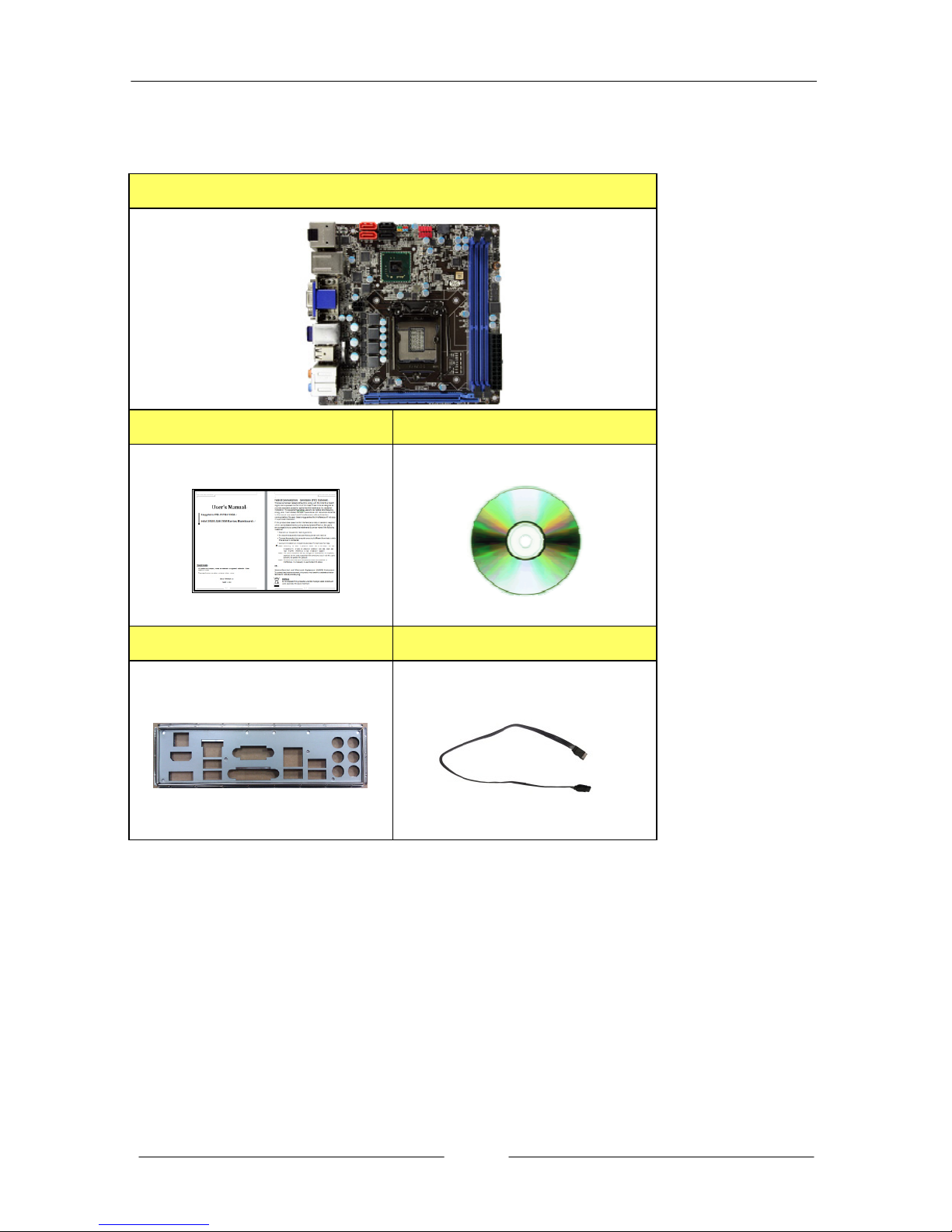
1-2 Package Contents
Your Sapphire mainboard comes with the following accessories.
1. Mainboard
2. Quick Installation Guide 3. Driver DVD
4. I/O Shield 5. SATA Data Cable *2
~ 5 ~
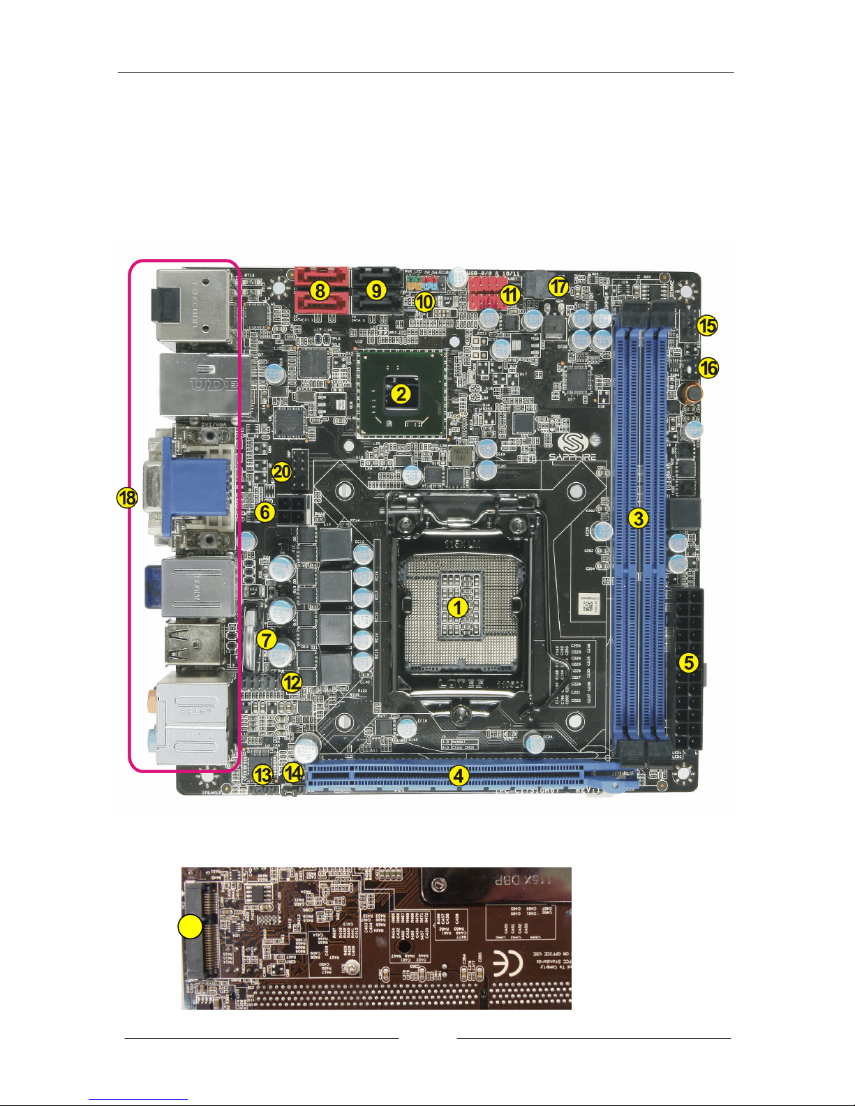
1-3 Mainboard Layout
The following figure shows the location of components on the mainboard. See
following page for description.
Component on front of mainboard:
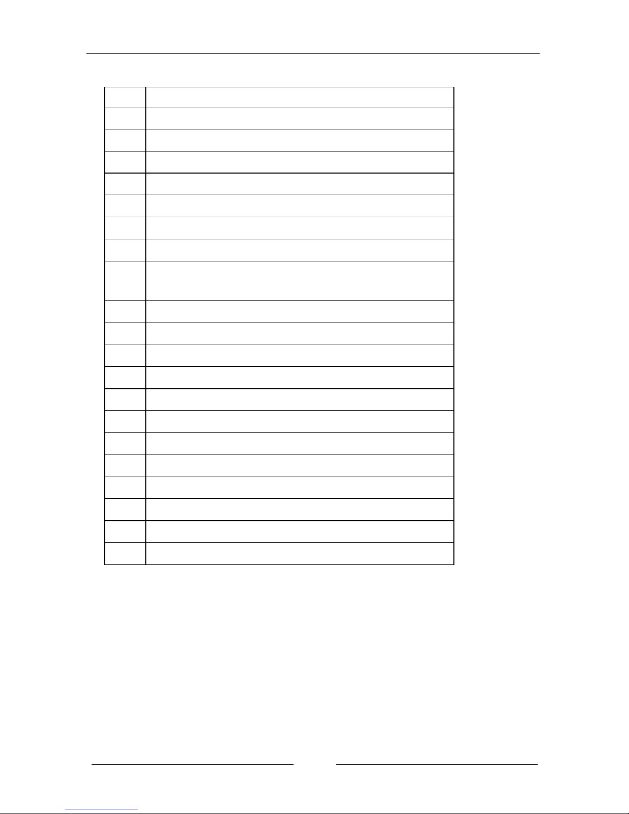
Component on back of mainboard:
19
~ 6 ~
Item Component description
1 CPU Socket 1155
2 Intel H67/H61 single Chip
3 DDR3 DIMM Slots 1-2
4 PCI-E 2.0 x16 Slot
5 24-Pin ATX Power Connector
6 4-pin ATX_12V Power Connector
7 Mainboard Battery
8
SATA3 Connectors *2 (For H67 model)
SATA2 Connectors *2 (For H61 model)
9 SATA2 Connectors *2
10 Front Panel Header
11 USB 2.0 Header *4
12 Front Panel Audio Header
13 Speaker Header
14 Clear CMOS Jumper
15 CPU Fan Header
16 Power Fan Header
17 32Mb SPI Flash
18 Back Panel Connectors (see next page for detail)
19 Mini PCI-E x1 Slot
20 Debug Port Connector (for factory test only)

~ 7 ~
I/O Back Panel
The I/O back panel for this mainboard is shown below. When installing the
mainboard into the computer case, use the bundled I/O shield to protect this
back panel.
1. Optical S/PDIF-Out
This SPDIF (Sony & Philips Digital Interconnect Format) connector is used
for digital audio transmission to external speakers/amplifier through an
optical fiber cable.
2. HDMI Port
The HDMI (High-Definition Multimedia Interface) provides an all-digital
audio/video interface to transmit the uncompressed audio/video signals
and is HDCP compliant. Connect the HDMI audio/video device to this port.
3. Display Port
The DisplayPort is a digital display interface standard. This connector is used
to connect a monitor with DisplayPort inputs.
4. LAN Ports with LEDs
The mainboard provides one standard RJ-45 jack for connecting to a Local
Area Network (LAN). Two LEDs are built into the RJ-45 LAN connector.
These LEDs indicate the status of the LAN.
LED LED Color LED state Indicates
A Green
Off LAN link is not established
On LAN link is established
Blinking LAN activity is occurring
B
N/A Off 10 Mb/s data rate
Green On 100 Mb/s data rate
Yellow On 1000 Mb/s data rate
~ 8 ~
5. USB 3.0 ports (two)
USB 3.0 ports are backwardly compatible with USB 2.0 devices. Supports
data transfer rates up to 4.8Gb/s (SuperSpeed).
6. VGA Port
The VGA female port provides connection to analogue VGA monitors.
7. DVI-D Port
The DVI-D (Digital Visual Interface-Digital) port provides a high-speed
digital interconnection between the computer and its display device.
Connect a monitor that supports DVI-D connection to this port. The DVI-D
port does not support analogue VGA monitors using a passive DVI to VGA
adapter.
Dual Display Configurations:
This mainboard provides four ports for video output: VGA, DVI-D, HDMI
and Display port. It displays combination of either two. Please refer to table
below for dual display configurations supported.
Supported configurations
VGA + DVI-D
VGA + Display Port
VGA + HDMI
DVI-D + Display Port
DVI-D + HDMI
Display Port + HDMI
8. Bluetooth
Bluetooth wireless technology is an interface intended for wireless
control/data communication
9. USB 2.0 Ports (Four)
The mainboard provides an OHCI (Open Host Controller Interface) Universal
Serial Bus root for attaching USB devices such as a keyboard, mouse or
other USB-compatible devices. Supports data transfer rates up to 480Mb/s.
~ 9 ~
10. Audio Ports
This mainboard provides 2, 6 or 8 channel audio. It is easy to differentiate
between the audio functions by referring to the color of the jacks.
Ports 2 channel 6 channel 8 channel
Blue Line-In Line-In Line-In
Lime Line-Out Front Stereo-Out Front Stereo-Out
Pink Min-In Min-In Min-In
Orange -- Center/Subwoofer Center/Subwoofer
Black -- Rear Stereo-Out Rear Stereo-Out
Gray -- -- Side Stereo-Out

~ 10 ~
Chapter 2 Installation
2-1 Before You Begin
Please take note of all precautions before you install anything on to the
mainboard or change any of the mainboard settings.
Turn off the power to your system and discharge your body’s static electric
charge by touching a grounded surface—for example, the metal surface of the
power supply—before performing any hardware procedure.
The manufacturer assumes no liability for any damage, caused directly or
indirectly, by improper installation of any components by unauthorized service
personnel. If you do not feel comfortable performing the installation, consult a
qualified computer technician.
Damage to system components, the mainboard, and injury to you may result if
power is applied during installation.
2-2 Installing the I/O Shield
The mainboard comes complete with an I/O shield. When installed in the chassis,
the shield blocks radio frequency transmissions, protects internal components
from dust and foreign objects, and promotes correct airflow within the chassis.
Install the I/O shield before installing the mainboard in the chassis. Place the
shield inside the chassis. Press the shield into place so that it fits tightly and
securely. If the shield does not fit, obtain a properly sized shield from the chassis
supplier.
2-3 Securing to the Chassis
When installing the mainboard, you have to secure the mainboard into the
chassis by fastening with nine screws. Please refer to your chassis manual for
instructions on installing.
~ 11 ~
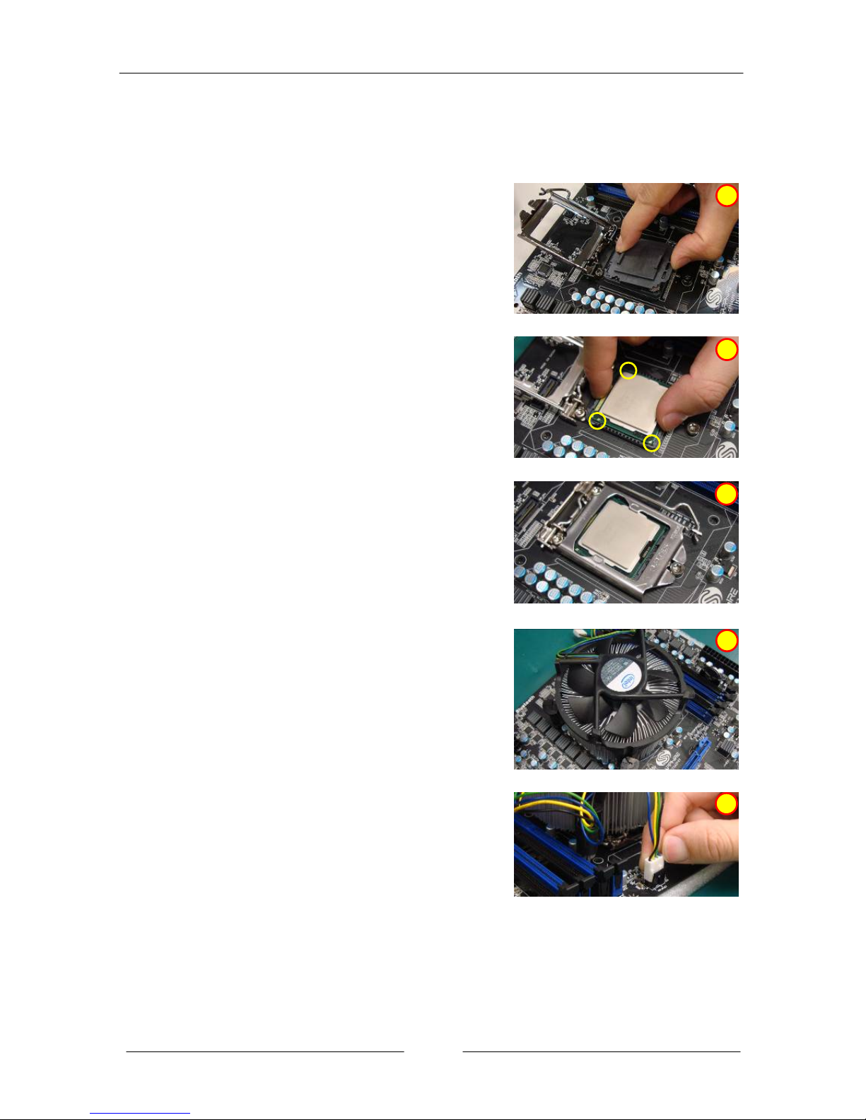
2-4 Installing the CPU and Fan Heatsink
To install the CPU:
1. Open the socket lever by pushing the lever
down and away from the socket. Remove the
protective socket cover from the socket. Do
not touch the socket contacts.
ÍNote:
Do not discard the protective socket cover. Be
sure to always replace the cover unless the
CPU is installed.
2. Align the CPU notches to the socket
protrusions. Place CPU straight down
without tilting or sliding it.
3. Close the load plate and engage the socket
lever.
4. To install fan heatsink, align the holes on the
mainboard. Press the four hooks down to
fasten the cooler. You will hear a “click” upon
full engagement. Gently rotate the cap
clockwise 1/4 turn to fasten the heatsink
onto the mainboard
5. Connect the 4-wire fan cable to the 4-pin
CPUFAN header on the mainboard.
PS:
Pictures for installation reference
only, the board may be different
from the actual.
1
2
3
4
5
 Loading...