

Page 1

Sapphire PURE CrossFireX 890GX
Motherboard
User Manual
Page 2

Federal Communications Commission (FCC) Statement
This equipment has been tested and found to comply with the limits for a Class B digital
device, pursuant to Part 15 of FCC Rules. These limits are designed to provide reasonable
protection against harmful interference in a residential installation. This equipment
generates, uses and can radiate radio frequency energy and, if not installed and used in
accordance with instructions contained in this manual, may cause harmful interference
to radio and television communications. However, there is no guarantee that interference
will not occur in a particular installation.
If this equipment does cause harmful interference to radio or television reception, which
can be determined by turning the equipment off and on, the user is encouraged to try to
correct the interference by one or more of the following measures:
- REORIENT OR RELOCATE THE RECEIVING ANTENNA
- INCREASE THE SEPARATION BETWEEN THE EQUIPMENT AND THE RECEIVER
- CONNECT THE EQUIPMENT INTO AN OUTLET ON A CIRCUIT DIFFERENT FROM
THAT OF THE RECEIVER
- CONSULT THE DEALER OR AN EXPERIENCED AUDIO/TELEVISION TECHNICIAN
NOTE: Connecting this device to peripheral devices that do not comply with Class B
requirements, or using an unshielded peripheral data cable, could also result in
harmful interference to radio or television reception.
The user is cautioned that any changes or modifications not expressly approved
by the party responsible for compliance could void the user‟s authority to operate
this equipment.
To ensure that the use of this product does not contribute to interference, it is
necessary to use shielded I/O cables.
Copyright
This manual is copyrighted with all rights reserved. No portion of this manual may be
copied or reproduced by any means.
While every precaution has been taken in the preparation of this manual, no responsibility
for errors or omissions is assumed. Neither is any liability assumed for damages resulting
from the use of the information contained herein.
Trademarks
All brand names, logos and registered trademarks mentioned are property of their
respective owners.
Trademark:
Electronic Emission Notices
Page 3

* Specifications and information contained in this documentation are furnished for information use only, and are
subject to change at any time without notice, and should not be construed as a commitment by manufacturer.
Environmental Protection Announcement
Do not dispose this electronic device into the trash while discarding. To minimize pollution
and ensure environment protection of mother earth, please recycle.
Box Included Checklist
Sapphire PC-AM3RS890G Motherboard
Cable for ATA 133 IDE
Sapphire Driver CD for Motherboard and Utilities
Cable for Serial ATA II and Power cable
Sappphire PC-AM3RS890G Motherboard User‟s Manual
Rear External I/O Shield
PCI-E X16 slot Switch Card
Page 4

ii
Environmental Safety Instruction
Avoid the dusty, humidity and temperature extremes. Do not place the product in
any area where it may become wet.
0 to 40 centigrade is the suitable temperature. (The figure comes from the request
of the main chipset)
Generally speaking, dramatic changes in temperature may lead to contact
malfunction and crackles due to constant thermal expansion and contraction from
the welding spots‟ that connect components and PCB. Computer should go
through an adaptive phase before it boots when it is moved from a cold
environment to a warmer one to avoid condensation phenomenon. These water
drops attached on PCB or the surface of the components can bring about
phenomena as minor as computer instability resulted from corrosion and oxidation
from components and PCB or as major as short circuit that can burn the
components. Suggest starting the computer until the temperature goes up.
The increasing temperature of the capacitor may decrease the life of computer.
Using the close case may decrease the life of other device because the higher
temperature in the inner of the case.
Attention to the heat sink when you over-clocking. The higher temperature may
decrease the life of the device and burned the capacitor.
Page 5

iii
INTRODUCTION
1 FEATURES OF MOTHERBOARD .................................................................................... 1
SPECIAL FEATURES OF MOTHERBOARD .................................................................. 2
2 SPECIFICATION ................................................................................................................... 3
3 LAYOUT DIAGRAM ........................................................................................................... 4
HARDWARE INSTALLATION
1 INSTALL CPU ..................................................................................................................... 7
2 INSTALL MEMORY ............................................................................................................ 9
3 EXPANSION CARDS ........................................................................................................... 10
CONNCTORS, HEADERS & JUMPERS SETTING
1 CONNECTORS ..................................................................................................................... 12
2 HEADERS .............................................................................................................................. 16
3 STARTING UP YOUR COMPUTER ................................................................................. 19
USEFUL SETUP
1 BIOS SETUP ........................................................................................................................ 20
2 DRIVER & FREE PROGRAM INSTALATION ............................................................... 36
USEFUL HELP
1 HOW TO UPDATE BIOS ................................................................................................... 48
2 Appendix
TABLE OF CONTENT
Page 6

1
Introduction
Features of motherboard
The AMD 890GX chipset motherboard series are based on the latest AMD 890GX
Chipset and the SB 850 chipset which supports: Phenom™ II X 4, Phenom™ II X3 ,
Phenom™ II X2 processor; Athlon™ II X4; Athlon™ II X3; Athlon™ II X2 processor
and Sempron AM3 CPU under 140 power consumption. With an integrated
low-latency high-bandwidth DDRIII memory controller and a highly-scalable Hyper
Transport technology-based system bus up to HT 3.0. AMD 890GX Platform Processor
Chipset motherboard series deliver the outstanding system performance and
professional desktop platform solution.
The AMD 890GX Series motherboards support new generation Socket AM3
processors with an integrated DDRIII memory controller for Dual channel DDRIII
1066 / DDRIII 1333 Module up to 16GB, also providing DDRIII 128Mb GPU side-port
Memory.The motherboard supports ULTRA ATA 133 connectors and Serial ATA3
with RAID 0, 1, 5,10 and JBOD functions which support up to two IDE and six Serial
ATA3 devices to accelerate hard disk drives and guarantee the data security without
failure in advanced computing performance.
The AMD 890GX motherboards provide 10/100/1000 LAN function with Gigabit LAN
chip which supports 10/100/1000Mbps data transfer rate. And the embedded
8-channel HD Audio CODEC is fully compatible with Sound Blaster Pro standards
that offer you with the home cinema quality and satisfying software compatibility.
The AMD 890GX Series motherboards deliver outstanding value and performance for
gamers, with a true bandwidth design for Multi-GPU configurations. This high
bandwidth architecture in the AMD 890GX chipset is with the flexibility for single or
dual card configurations. The AMD 890GX chipset provides 2 x16@8 lane PCI
Express 2.0 slots to support simultaneous operation of graphics cards for astonishing
performance with brilliant and intense 3D graphics.
AMD 890GX Series motherboard series offer two PCI-Express 2.0x16@ 8 lanes
graphics slots. When PE4 installed switch card, the PE1 becomes PCI-Express
2.0x16@ 16 lanes graphics slot. One PCI Express x1 I/O slot tackling the most
demanding multimedia tasks nowadays.The AMD 890GX motherboards also carry
one 32-bit PCI slot and one mini-PCIE slot to guarantee the rich connectivity for the
I/O peripheral devices. This motherboard support Hybrid CrossFireX function, the
VGA Card on PE1 or PE4 will activate a Hybrid CrossFire with the onboard VGA Card,
the performance will be increased 15% to 75%.
Embedded USB controllers as well as capability of expanding to 12 of USB2.0
functional ports delivering 480Mb/s bandwidth of rich connectivity, these
motherboards meet the future USB demands which are also equipped with hardware
monitor function on system to monitor and protect your system and maintain your
non-stop business computing.
Some special features--- CPU Smart Fan / CPU Vcore 7-shift / OC-CON / Debug
Port /3D Audio/DIY Clear/ Power on button/ Reset button in this motherboard are
Page 7

2
designed for power user to use the over-clocking function in more flexible ways. But
please be caution that the over-clocking maybe causes the fails in system reliabilities.
This motherboard provides the guaranteed performance and meets the demands of
the next generation computing. But if you insist to gain more system performance with
variety possibilities of the components you choose, please be careful and make sure
to read the detailed descriptions of these value added product features, please get
them in the coming section.
Special Features of Motherboard
CPU Smart Fan---( The Noise Management System )
It‟s never been a good idea to gain the performance of your system by sacrificing its acoustics.
CPU Smart Fan Noise Management System is the answer to control the noise level needed for
now-a-day‟s high performance computing system. The system will automatically increase the fan
speed when CPU operating loading is high, after the CPU is in normal operating condition, the
system will low down the fan speed for the silent operating environment. The system can provide
the much longer life cycle for both CPU and the system fans for game use and business
requirements.
CPU Vcore 7-Shift--- (Shift to Higher Performance)
The CPU voltage can be adjusted up by 7 steps for the precisely over-clocking of extra demanding
computing performance.
OC-CON ---(High-polymer Solid Electrolysis Aluminum Capacitors)
The working temperature is from 55 degrees Centigrade below zero to 125 degrees Centigrade,
OC-CON capacitors possess superior physical characteristics that can be while reducing the
working temperature between 20 degrees Centigrade each time, intact extension 10 times of
effective product operation lives, at not rising degrees Centigrade of working temperatures each
time a relative one, life of product decline 10% only too.
Debug Port --- (The Professional Hardware Diagnosis System )
Being bugged of abnormal system failure through the tossed and turned nights no more, the
embedded Hardware Debug Port offers you the real-time visual system healthy for the demanding
usage of computing. No more bugging by unknown system failure and no more time wasted in the
first moment of 24-hour nonstop ping business computing, the embedded Debug Port will turn you
into a well training hardware professional with the seeing system situation. (The Post Code please
refer to appendix)
3D Audio—(3D Audio Sound Effect)
OP with two-stage Butterworth filter and quadruple noninverting amplifier enhances bass effect
under the 100MHz range to perfect audio effect, brings you stunning shock experience in video
game, true-to-life simulated feeling when watching films and the greatest touch as that in the
concert. There is a 3D Audio button integrated on the board. Press down the button to enable 3D
audio effect or press again to disabled it.
DIY Clear-The CMOS button is to facilitate the clear CMOS process for power user overclocking
function. The user can easily clear or restore CMOS setting by pressing the button without tacking
trouble to remove the case and locate the jumper for clear CMOS .
Power On Button- You can easily start the computer by pressing down this button for a few
seconds, without troubling yourself to locate the front panel jumpers to find the Power on jumper.
Reset Button..: You can easily restart the computer by pressing down this button for a few
seconds, without troubling yourself to locate the front panel jumpers to find the reset jumper.
Page 8

3
Specification
Spec
Description
Design
ATX form factor 4 layers PCB size: 30.5cm x24.5cm
Chipset
AMD 890GX North Bridge Chipset
AMD SB 850 South Bridge Chipset
CPU Socket AM3
Support AMD AM3 CPU : Phenom™ II X 4, Phenom™ II X3 ,
Phenom™ II X2 processor; Athlon™ II X4; Athlon™ II X3; Athlon™ II
X2 processor and Sempron AM3 CPU
Power consumptionsupport to 140 W CPU
Support HT 3.0
Memory Slot
240-pin DDRIII Module slot x 4
Support 4pcs DDRIII 1066 /DDRIII 1333 Modules Expandable to 8GB
Dual channel supported
Expansion Slot
2pcs PCI-Express 2.0x16 by 8 lane
1pcs PCI-Express 2.0 x1 slot
1pcs 32-bit PCI slot
1pcs of mini-PCIE slot
Integrate IDE and
Serial ATA2 RAID
JMC chip support one IDE HD connector that deliver the data transfer
rate up to 133 MB/s for 2 IDE Devices
SB 850 supports 6 Serial ATAIII 6 Gb/s connectors with RAID 0, 1,
10,5 and JBOD function
Gigabit LAN
Integrated Gigabit LAN chip.
Support Fast Ethernet LAN function of providing 10Mb/100Mb/1000
Mb/s data transfer rate
8 CH-Audio
Realtek Azalia 8-channel Audio Codec integrated
Support 8-channel 3D surround & Positioning Audio
Audio driver and utility included
Sideport Memory
Embedded DDR III 128Mb sideport memory
BIOS
AMI 16MB DIP Flash ROM
Multi I/O
PS/2 keyboard and PS/2 mouse connectors
Coaxial /Optical SPDIF_OUT connectors
HDMI connector / DVI connector / VGA connector
ESATA connector x1
RJ-45 connector x1
USB2.0 port x 4 and headers x 4
Audio connector x1 (8CH Audio)
Floppy disk drive connector x1 /Hard Disk Drive Connector x1
Serial port header x1
HDMI-SPDIF header x1
IR header x1
Page 9
4
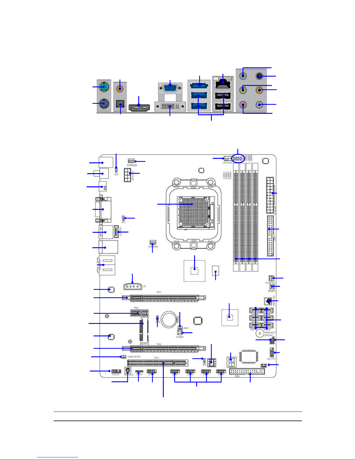
Layout Diagram
Rear I / O for HA09
16 MBit DIP BIOS
Front Panel Header
ATA 133 IDE
Conn.(IDE1)
AM3 CPU Socket
ATX Power Conn.
PCI Slot
PS2 KB/Mouse Port
Audio Connector
(J1)
RJ-45 Over
USB Connectors
(UL1)
DDR III Slot x 4
ATX 12V
Power Connector
Realtek ALC888
Audio Decode
CDIN
Gigabit LAN Chip
Speaker Header
USB Header
(USB1, 2,3,4)
Power Led Header
AMD 890GX Chipset
AMD SB 850 Chipset
Front Panel
AudioHeader
KBMB/USB Power On(JP3)
(E-SATA1)
IR Header
Reset Button
Power on Button
Floppy Disk Connector
CMOS1
E-SATA Over
USB Connectors
(CN1)
HDMI-SPDIF
Header
CPUFAN
SATA III
Connectors
4-pin PWR Connector
CHA FAN
PCI Express 2.0 x16
by 8-lane
HDMI Connector
VGA over DVI
Connector
PCI Express 2.0 x1
SYSFAN2
ESATA
Connector
Clear CMOS (JBAT)
DDRIII 128Mb GPU Memory
COM
Header
USB Connectors
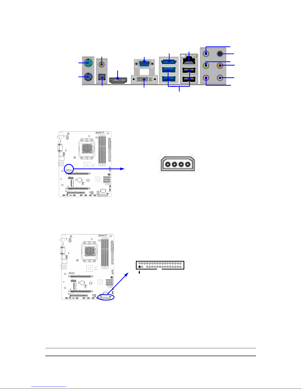
PS/2 Mouse
Port
PS/2 Keyboard
Port
RS-OUT
Line-OUT
CS-OUT
SS-OUT
MIC-IN
VGA
Connector
DVI
Connector
Line-IN
HDMI
Connector
RJ-45
Connector
SYSFAN1
Coaxial
SPDIF_OUT Connector
Optical
SPDIF_OUT Connector
Coaxial/Optical
SPDIF_OUT Connectors
Mini-PCIE Slot
PCI Express 2.0 x16
by 8-lane
3D Audio Button
JP4
JP2
Debug Port
G.P.I. LED
JP1
Page 10

5
Jumpers
Jumper
Name
Description
JP1/JP2
USB Power On Enabled/Disabled
3-pin Block
JP3
KB/USB Power On Enabled/Disabled
3-pin Block
JBAT
Clear CMOS Header
2-pin Block
Connectors
Connector
Name
Description
ATXPWR1
ATX Power Connector
24-pin Block
ATX12V
ATX 12V Power Connector
8-pin Block
J3
Power Connector
4-Pin Block
KB
PS/2 Mouse & PS/2 Keyboard Connector
6-pin Female
SPDIF_OUT1
/SPDIF_OUT2
Coaxial/Optical SPDIF_OUT Connector
1-phone Jack
USB from CN1, UL1
USB2.0 Port Connector
4-pin Connector
ESATA from CN1
External SATA III Connector
7-pin Connector
RJ-45LAN from UL1
Gigabit LAN Port Connector
8-pin Connector
J1
8-CH HD Audio Connector
6- phone jack Conn.
FDD
Floppy Driver Connector
34-pin Block
IDE
Primary IDE Connector
40-pin Block
SATA1~SATA6,
E-SATA1
Serial ATAIII Connectors
7-pin Connector
CN1 for ESATA
External Serial ATAIII Connector
7-pin Connector
VGA1
D-Sub Connector
15-pin Connector
DVI
Digital Visual Interface
29-pin Connector
HDMI
High-Definition Multimedia
19-pin Connector
Headers
Header
Name
Description
AUDIO1
Front Panel SPEAKER, MIC header
9-pin Block
USB1, USB2,USB3,USB4
USB Port Headers
9-pin Block
SPEAK
PC Speaker connector
4-pin Block
PWR LED1
Power LED
3-pin Block
JW_FP1 (HD LED/PWR
LED/ Reset/ Power Button)
Front Panel Header
9-pin Block
SYSFAN1/2, CHAFAN
FAN Headers
3-pin Block
CPUFAN
FAN Header
4-pin Block
CDIN1
CD Audio-In Header
4-pin Block
IR
IR infrared module Headers
5-pin Block
COM1
Serial Port COM1 Header
9-pin Block
HDMI-SPDIF
SPDIF Out header
2-pin Block
Expansion Sockets
Socket/Slot
Name
Description
ZIF Socket AM3
CPU Socket
938-pin PGAB CPU Socket
DIMM1~4
DDRIII Module Socket
240-pin DDRIII Module Socket
PCI1
PCI Slots
32-bit PCI Local Bus Expansion slots
PE2
PCI-Express 2.0 x1Slot
PCI-Express 2.0 x1 Expansion Slots
PE1,PE4
PCI-Express 2.0x16 Slot
PCI-Express 2.0x16 Expansion Slots
MINIPCIEB1
Mini-PCIE Slot
Mini-PCIE Expansion Slot
Page 11
6
Hardware Installation
WARNING! Turn off your power when adding or removing expansion cards or
other system components. Failure to do so may cause severe
damage to both your motherboard and expansion cards.
Hardware installation Steps
Before using your computer, you had better complete the following steps:
1. Check motherboard jumper setting
2. Install CPU and Fan
3. Install System Memory (DIMM)
4. Install Expansion cards
5. Connect IDE and Front Panel /Back Panel cable
6. Connect ATX Power cable
7. Power-On and Load Standard Default
8. Reboot
9. Install Operating System
10. Install Driver and Utility
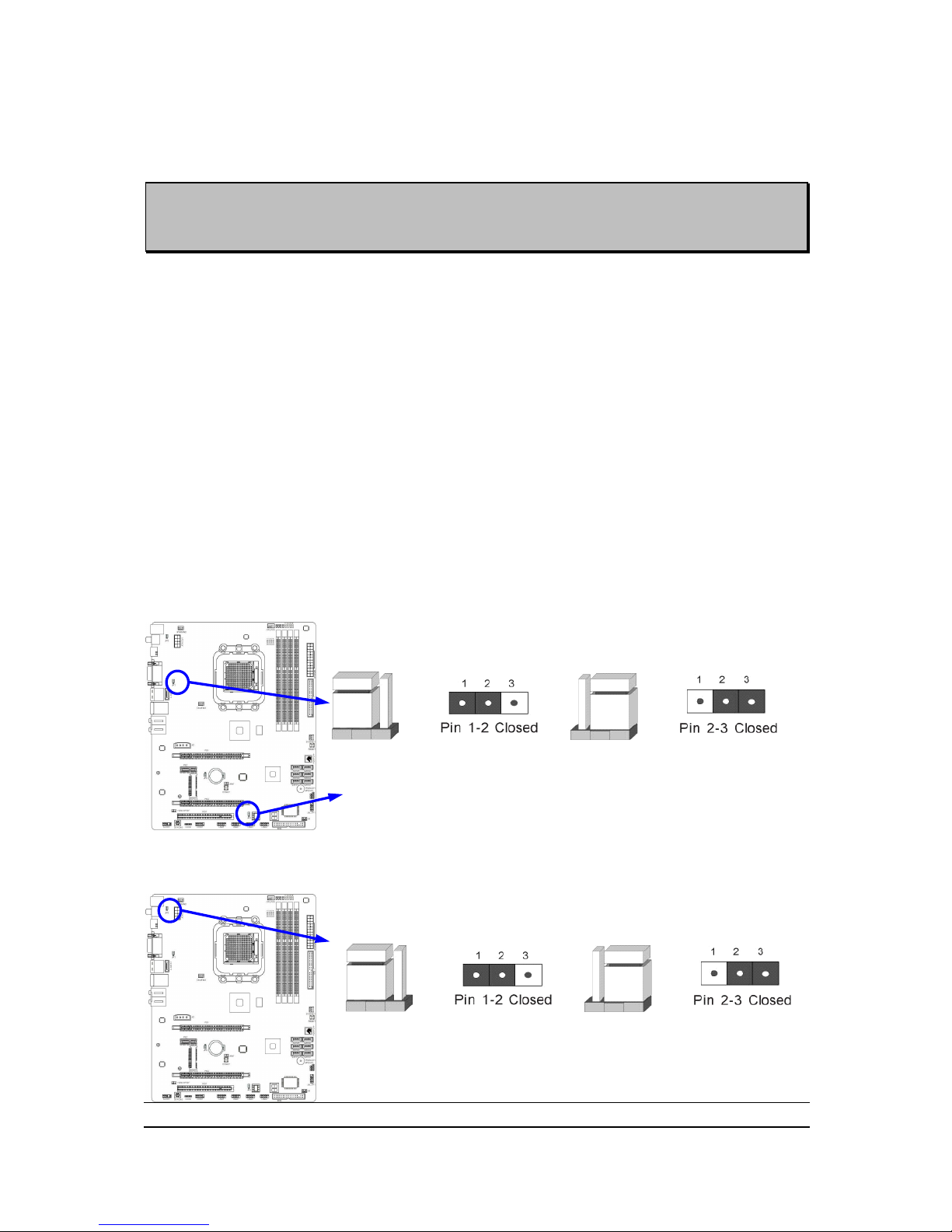
Checking Motherboard‟s Jumper Setting
(1) USB function Enabled/Disabled: JP1/JP2
KB & USB Power On Setting
2-3 Closed: KB/USB Power ON Enabled
JP1
JP1
1-2 Closed: KB/USB Power ON Disable (Default)
(2) KB/USB function Enabled/Disabled: JP3
KB & USB Power On Setting
2-3 Closed KB/USB Power ON Enabled
JP1
JP1
1-2 Closed KB/USB Power ON Disable (Default)
Page 12
7
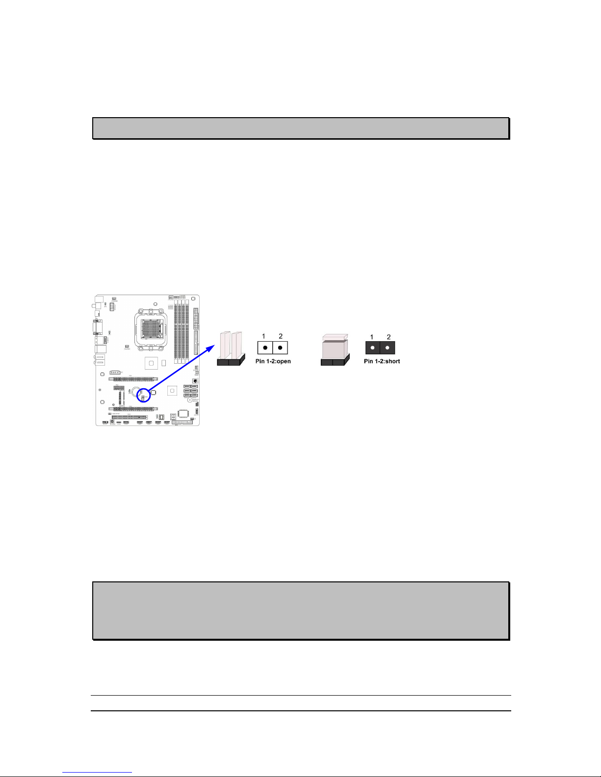
(3) CMOS RAM Clear (2-pin): JBAT
A battery must be used to retain the motherboard configuration in CMOS RAM
short 1-2 pins of JBAT to clear the CMOS data.
WARNNING:Please remove or turn off the power supply before CMOS clear!
To clear the CMOS, follow the procedure below:
1. Turn off the system and unplug the AC power
2. Remove ATX power cable from ATX power connector
3. Locate JBAT and short pins 1-2 for a few seconds, if shorted with the jump cap,
short for a few seconds then pull out the hat.
4. Connect ATX power cable back to ATX power connector
Note: When should clear CMOS
1. Troubleshooting
2. Forget password
3. After over clocking system boot fail
CMOS Clear Setting
1-2 Short: CMOS Clear
JBAT
1-2 Open: Normal
Install CPU
About AMD AM3 CPU Installation
This motherboard provides a socket AM3 surface mount, Zero Insertion Force (ZIF)
socket, referred to as the mPGA socket supports AMD AM3 processor.
The CPU that comes with the motherboard should have a cooling FAN attached to
prevent overheating. If this is not the case, then purchase a correct cooling FAN
before you turn on your system.
WARNING! Be sure that there is sufficient air circulation across the processor‟s
heatsink and CPU cooling FAN is working correctly, otherwise it may
cause the processor and motherboard overheat and damage, you
may install an auxiliary cooling FAN, if necessary.
To install a CPU, first turn off your system and remove its cover. Locate the ZIF
socket and open it by first pulling the level sideways away from the socket then
upward to a 90-degree angle. Insert the CPU with the correct orientation as shown
Page 13

8
below. The notched corner should point toward the end of the level. Because the CPU
has a corner pin for two of the four corners, the CPU will only fit in the orientation as
shown.
CPU ZIF mPGAB Socket
Colden Arrow
Socket AM3
When you put the CPU into the ZIF socket, No force required to insert of the CPU,
and then press the level to locate position slightly without any extra force.
AMD AM3 Processor Family
Cooling Solutions
As processor technology pushes to faster speeds and higher performance with increasing
operation clock, thermal management becomes increasingly crucial while building computer
systems. Maintaining the proper computing environment without thermal increasing is the key to
reliable, stable, and 24 hours system operation. The overall goal is keeping the processor
below its specified maximum case temperature. Heatsinks induce improved processor heat
dissipation through increasing surface area and concentrated airflow from attached active
cooling fans. In addition, interface materials allow effective transfers of heat from the
processor to the heatsink. For optimum heat transfer, AMD recommends the use of thermal
grease and mounting clips to attach the heatsink to the processor.
Please refer to the website below for collection of heatsinks evaluated and recommended for
Socket AM3 processors by AMD. In addition, this collection is not intended to be a
comprehensive listing of all heatsinks that support Socket-AM3 processors.
Page 14
9
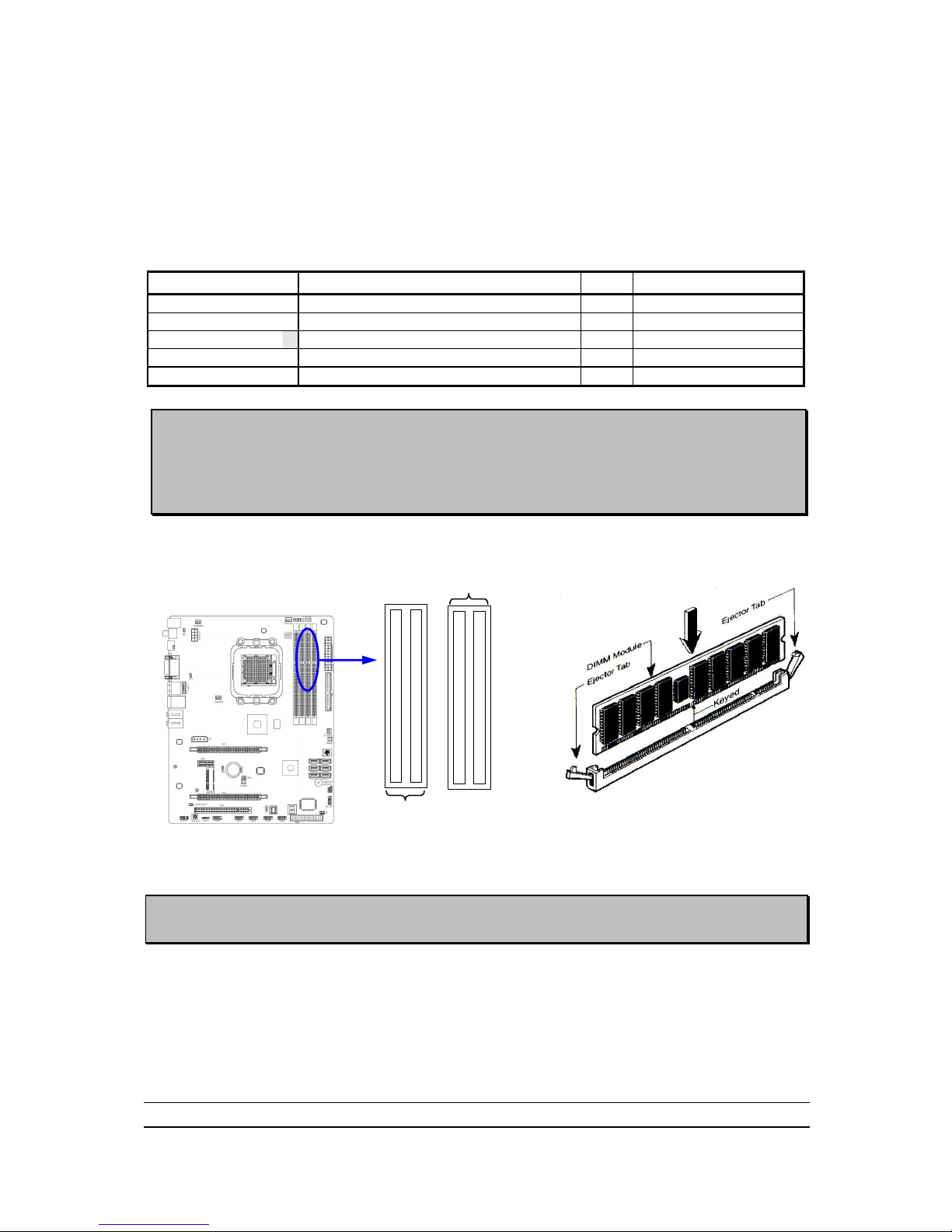
Install Memory
This motherboard provides four 240-pin DDR III DUAL INLINE MEMORY MODULES
(DIMM) socket for DDR III memory expansion available to maximum memory volume
of 8GB DDRIII SDRAM.
Valid Memory Configurations
Bank
240-Pin DIMM
PCS
Maximum Capacity
Bank 0, 1 (DIMM1)
DDR III 1066/ DDR III1333
X1
2GB
Bank 2, 3 (DIMM2)
DDR III 1066/ DDR III1333
X1
2GB
Bank 4, 5 (DIMM3)
DDR III 1066/ DDR III1333
X1
2GB
Bank 6, 7 (DIMM4)
DDR III 1066/ DDR III1333
X1
2GB
Total
System Memory (Max4GB)
4
16GB
Dual channel Limited!
1. Dual channel function only supports when 2 DIMM Modules plug in either both DIMM1
& DIMM2, or four DIMM Modules please plug in DIMM1~DIMM4.
2. Memory modules must be the same type, same size, same frequency for dual channel
function.
Install DDR SDRAM modules to your motherboard is not difficult, you can refer to
figure below to see how to install a 240-Pin DDRIII 1066/DDRIII 1333 SDRAM
module.
DIMM2 (BANK2+BANK3)
DIMM1 (BANK0+BANK1)
DIMM4 (BANK6+BANK7)
DIMM3 (BANK4+BANK5)
DIMM1 & DIMM2: Dual Channel 1
Graph 2-4
NOTE! When you install DIMM module fully into the DIMM socket the eject tab should be
locked into the DIMM module very firmly and fit into its indention on both sides.
Page 15
10
Expansion Cards
WARNING!
Turn off your power when adding or removing expansion cards or other
system components. Failure to do so may cause severe damage to both
your motherboard and expansion cards.
Procedure for Expansion Card Installation
1. Read the documentation for your expansion card and make any necessary
hardware or software setting for your expansion card such as jumpers.
2. Remove your computer‟s cover and the bracket plate on the slot you intend to
use.
3. Align the card‟s connectors and press firmly.
4. Secure the card on the slot with the screen you remove above.
5. Replace the computer system‟s cover.
6. Set up the BIOS if necessary.
7. Install the necessary software driver for your expansion card.
Assigning IRQs for Expansion Card
Some expansion cards need an IRQ to operate. Generally, an IRQ must exclusively
assign to one use. In a standard design, there are 16 IRQs available but most of
them are already in use.
Standard Interrupt Assignments
IRQ
Priority
Standard function
0
N/A
System Timer 1 N/A
Keyboard Controller
2
N/A
Programmable Interrupt
3 *
8
Communications Port (COM2)
4 *
9
Communications Port (COM1)
5 *
6
Sound Card (sometimes LPT2)
6 *
11
Floppy Disk Controller
7 *
7
Printer Port (LPT1)
8
N/A
System CMOS/Real Time Clock
9 *
10
ACPI Mode when enabled
10 *
3
IRQ Holder for PCI Steering
11 *
2
IRQ Holder for PCI Steering
12 *
4
PS/2 Compatible Mouse Port
13
N/A
Numeric Data Processor
14 *
5
Primary IDE Channel
15 *
1
Secondary IDE Channel
* These IRQs are usually available for ISA or PCI devices.
Page 16
11
NOTE! If using PCI cards on shared slots, make sure that the drivers support “Shared
IRQ” or that the cards don‟t need IRQ assignments. Conflicts will arise between
the two PCI groups that will make the system unstable or cards inoperable.
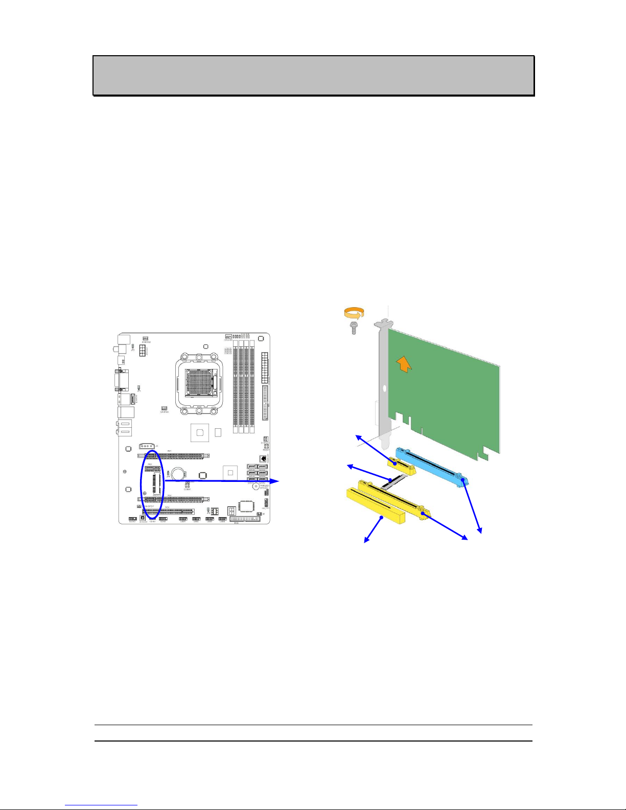
PCI Express2.0 Slots
AMD 890GX Series motherboard series offer two PCI-Express 2.0x1 6@ 8 lanes
graphics slots. When PE4 installed switch card, the PE1 will doubled its bandwidth.
One PCI Express x1 I/O slot tackling the most demanding multimedia tasks nowadays.
The AMD 890GX motherboards also carry one 32-bit PCI slot and one mini-PCIE slot
to guarantee the rich connectivity for the I/O peripheral devices.
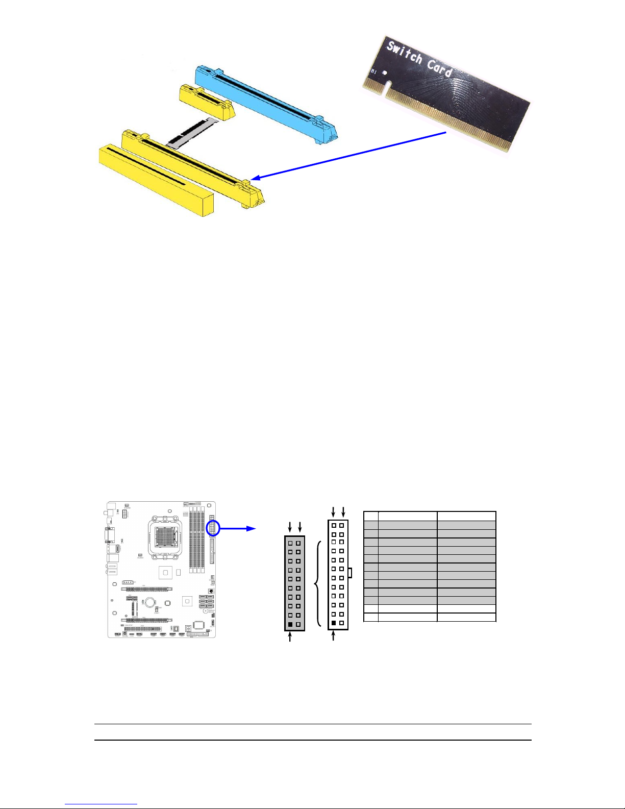
PCI Express Switch Card
Install PCI-E Switch Card to PCI-Express2.0 x16 graphics slot can double PCI-E X16 VGA
card installed transfer rate up to 16 lane; 16Gbyte/sec. Please be noted that Switch Card must
plug in PE4
PCI-E2.0 x1 Slot
32-bit PCI Slot
PCI-E 2.0 x16 Slot by 8-lane
Mini-PCIE Slot
Page 17
12
Connectors and Headers
Connectors
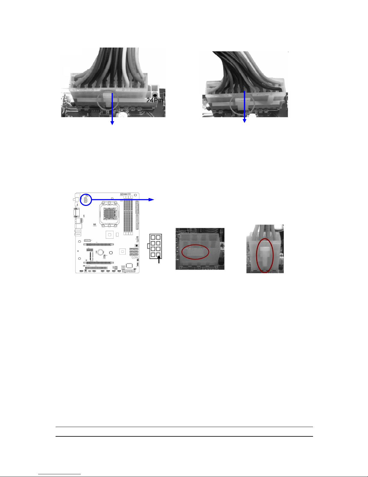
(1) Power Connector (24-pin block) : ATXPWR1
ATX Power Supply connector: This is a new defined 24-pins connector that
usually comes with ATX case. The ATX Power Supply allows using soft power
on momentary switch that connect from the front panel switch to 2-pins Power
On jumper pole on the motherboard. When the power switch on the back of the
ATX power supply turned on, the full power will not come into the system board
until the front panel switch is momentarily pressed. Press this switch again will
turn off the power to the system board.
** We recommend that you use an ATX 12V Specification 2.0-compliant power
supply unit (PSU) with a minimum of 350W power rating. This type has 24-pin
and 4-pin power plugs.
** If you intend to use a PSU with 20-pin and 4-pin power plugs, make sure that the
20-pin power plug can provide at least 15A on +12V and the power supply unit
has a minimum power rating of 350W. The system may become unstable or may
not boot up if the power is inadequate.
** If you are using a 20-pin power plug, please refer to Figure1 for power supply
connection. Power plug form power supply and power connectors from
motherboard both adopt key design to avoid mistake installation. You can insert
the power plug into the connector with ease only in the right direction. If the
Pin 1
ROW1
ROW2
24-Pin
ROW1
ROW2
Pin 1
20-Pin
PIN
ROW1
ROW2
1
3.3V
3.3V
2
3.3V
-12V
3
GND
GND
4
5V
Soft Power On
5
GND
GND
6
5V
GND
7
GND
GND
8
Power OK
-5V
9
+5V (for Soft Logic)
+5V
10
+12V
+5V
11
+12V
+5V
12
+3V
GND
Page 18
13
direction is wrong it is hard to fit in and if you make the connection by force if is
possible.
Figure1:20-pin power plug Figure 2:24-pin power plug
(2)ATX 12V Power Connector (8-pin block) : ATX12V1
This is a new defined 8-pins connector that usually comes with ATX Power
Supply. The ATX Power Supply which fully supports Socket AM3 processor
must including this connector for support extra 12V voltage to maintain system
power consumption. Without this connector will cause system unboot because
the power supply can not provide sufficient current for system.
Pin 1
(3) PS/2 Mouse & PS/2 Keyboard Connector: KB
The connectors are for PS/2 keyboard and PS/2 Mouse.
(4) USB Port connector: CN1/ UL1 for USB
The connectors are 4-pin connector that connects USB devices to the system
board.
(5) LAN Port connector: UL1 for RJ45 LAN
The connector is standard RJ45 connector for Network. It supports
10M/100Mb/1000Mb s data transfer rate
(6) Audio Line-In, Lin-Out, MIC, RS-Out, CS-Out,SS-Out connector : J1
These Connectors are 6 Phone-Jack for LINE-OUT, LINE-IN, MIC, RS-Out,
CS-Out,SS-Out audio connections.
Line-in : (BLUE)
Audio input to sound chip
Line-out : (GREEN) Audio output to speaker
MIC : (PINK)
Microphone Connector
RS-OUT : (BLACK) Rear-Surround audio output
CS-OUT : (ORANGE) Center/ Subwoofer audio output
SS-OUT: (GRAY) Side-Surround audio output
Page 19
14
(7) Large 4-Pin Power Connector :J2 Power Connector
The connectors are 4-pin connector that supports extra 12V / 5V power to your
system
(8) Floppy drive Connector (34-pin block): FDD
This connector supports the provided floppy drive ribbon cable. After connecting
the single plug end to motherboard, connect the two plugs at other end to the
floppy drives.
Floppy Drive Connector
Pin 1
FDD
(9) Primary IDE Connector (40-pin block): IDE1
This connector supports the provided IDE hard disk ribbon cable. After
connecting the single plug end to motherboard, connect the two plugs at other
end to your hard disk(s). If you install two hard disks, you must configure the
second drive to Slave mode by setting its jumpers accordingly. Please refer to
the documentation of your hard disk for the jumper settings.
ESATA
Connector
USB Connectors
PS/2 Mouse
Port
PS/2 Keyboard
Port
RS-OUT
Line-OUT
CS-OUT
SS-OUT
MIC-IN
VGA
Connector
DVI
Connector
Line-IN
HDMI
Connector
RJ-45
Connector
Coaxial
SPDIF_OUT Connector
Optical
SPDIF_OUT Connector
Page 20

15
IDE Connector
Pin 1
IDE1
Two hard disks can be connected to each connector. The first HDD is referred
to as the “Master” and the second HDD is referred to as the “Slave”.
For performance issues, we strongly suggest you don‟t install a CD-ROM or
DVD-ROM drive on the same IDE channel as a hard disk. Otherwise, the system
performance on this channel may drop.
(10) Serial-ATAIII Port connector:SATA1~SATA6; E-SATA1
This connector supports the provided SATA III hard disk cable to connecting the
motherboard with serial ATAIII hard disk. E-SATA1 is not for SATA harddrive ,it is
only for connecting t one of the SATA device from SATA1~SATA6 to activate the
ESATA connector.
SATA1
SATA2
SATA3
SATA4
SATA5
SATA6
SATA II Connectors
E-S ATA1
(11) ESATA Port: CN1 for ESATA
This connector supports the External Serial ATA2 (ESATA) enable the full SATA
interface speed outside the chassis, up to 6Gb/s. The ESATA port can be
enabled only when the E-SATA 1 is connected to one of SATA 1~SATA6.
(12) D-Sub 15-pin Connector: VGA1
VGA is the 15-pin D-Subminiature female connector; it is for the display devices,
such as the CRT monitor, LCD monitor and so on.
(13) Digital Visual Interface: DVI
This interface standard designed to maximize the visual quality of digital display
devices such as flat panel LCD computer displays and digital projectors.
(14) High-Definition Multimedia Interface: HDMI
This point-to-point interface is for audio and video signals designed as a
single-cable solution for home theater and consumer electronics equipment.
NOTE! DVI and HDMI Connector can not be used at the same time.
(15) Coaxial/Optical SPDIF _OUT header: SPDIF_OUT1/SPDIF_OUT2
Page 21

16
The SPDIF output is capable of providing digital audio to external speakers or
compressed AC3 data to an external Dolby digital decoder. Use this feature only
when your stereo system has digital input function. SPDIF_OUT1(above) is
coaxial SPDIF_OUT connector while SPDIF_OUT2(below) is optical
SPDIF_OUT connector.
Headers
(1) Line-Out/MIC Header for Front Panel (9-pin): AUDIO1
These headers connect to Front Panel Line-out, MIC connector with cable.
Line-Out, MIC Headers
AUDIO
Pin 1
Lineout2-L
Lineout2-R
Sense-FB
Audio-GND
LINE2-JD
Audio-JD
2 9 10
KEY
MIC2-L
MIC2-JD
MIC2-R
(2) USB Port Headers (9-pin): USB1/USB2/USB3/USB4
These headers are used for connecting the additional USB port plug. By
attaching an option USB cable, your can be provided with two additional USB
plugs affixed to the back panel.
USB Port Headers
Pin 1
USB
VCC
-DATA
GND
+DATA
VCC
OC
-DATA
GND
+DATA
(3)Speaker connector: SPEAKER
This 4-pin connector connects to the case-mounted speaker. See the figure
below.
(4) Power LED: PWR LED
Page 22

17
The Power LED is light on while the system power is on. Connect the Power
LED from the system case to this pin.
(5) Hard disk Activity LED: HD LED
This connector connects to the hard disk activity indicator light on the case.
(6) Reset switch lead: RESET
This 2-pin connector connects to the case-mounted reset switch for rebooting
your computer without having to turn off your power switch. This is a preferred
method of rebooting in order to prolong the lift of the system‟s power supply.
See the figure below.
(7) Power switch: PWR BTN
This 2-pin connector connects to the case-mounted power switch to power
ON/OFF the system.
System Case Connections
HDLED
RESET
VCC5
GND
VCC5
PWR LED
PWRBTN
PWRBTN
PWRLED
HDDLE
D
RSTSW
NC
GND
JW FP
Pin 1
SPEAK
SPKR
GND
NC
VCC5
Pin 1
PWRLED
Pin 1
(8) FAN Power Headers: SYSFAN1, SYSFAN2, CHAFAN (3-pin), CPUFAN (4-pin)
These connectors support cooling fans of 350mA (4.2 Watts) or less, depending
on the fan manufacturer, the wire and plug may be different. The red wire
should be positive, while the black should be ground. Connect the fan‟s plug to
the board taking into consideration the polarity of connector.
FAN Power Headers
3
1
CPUFAN
1
4
GND
+12V
CPUFAN IN
CPUFAN OUT
CHAFAN
1
3
SYSFAN2
3
1
SYSFAN1
(9) CD Audio-In Headers (4-pin): CDIN1
CDIN are the connectors for CD-Audio Input signal. Please connect it to
CD-ROM CD-Audio output connector.
Page 23

18
CD Audio-In Headers
CDIN
1 4
(10) IR infrared module Headers (5-pin): IR
This connector supports the optional wireless transmitting and receiving infrared
module. You must configure the setting through the BIOS setup to use the IR
function.
IR infrared module Headers
IR
Pin 1
GND
IRRX
NC
VCC5
IRTX
2
5
6
(11) Serial COM Port header: COM1
COM1 is the 9-pin block pin-header. The On-board serial port can be disabled
through BIOS SETUP.
Serial COM Port 9-pin Block
Pin1
(12) HDMI-SPDIF Out header: HDMI_SPDIF
The SPDIF output is capable of providing digital audio to external speakers or
compressed AC3 data to an external Dolby digital decoder. Use this feature only
when your stereo system has digital input function. Some of the VGA Card need
connect SPDIF-IN Connector,so its HDMI Port can make sounds .
Page 24

19
HDMI_SPDIF Header
1
GND
2
HDMI_SPDIF_OUT
Starting Up Your Computer
1. After all connections are made, close your computer case cover.
2. Be sure all the switch are off, and check that the power supply input voltage is set
to proper position, usually in-put voltage is 220V240V or 110V120V depending
on your country‟s voltage used.
3. Connect the power supply cord into the power supply located on the back of your
system case according to your system user‟s manual.
4. Turn on your peripheral as following order:
a. Your monitor.
b. Other external peripheral (Printer, Scanner, External Modem etc…)
c. Your system power. For ATX power supplies, you need to turn on the power
supply and press the ATX power switch on the front side of the case.
5. The power LED on the front panel of the system case will light. The LED on the
monitor may light up or switch between orange and green after the system is on.
If it complies with green standards or if it is has a power standby feature. The
system will then run power-on test. While the test is running, the BIOS will alarm
beeps or additional message will appear on the screen.
If you do not see any thing within 30 seconds from the time you turn on the power.
The system may have failed on power-on test. Recheck your jumper settings and
connections or call your retailer for assistance.
Page 25

20
6. During power-on, press <Delete> key to enter BIOS setup. Follow the
instructions in BIOS SETUP.
7. Power off your computer: You must first exit or shut down your operating
system before switch off the power switch. For ATX power supply, you can
press ATX power switching after exiting or shutting down your operating system.
If you use Windows 9X, click “Start” button, click “Shut down” and then click
“Shut down the computer?” The power supply should turn off after windows
shut down.
Useful Setup
BIOS Setup
The BIOS is a program located on a Flash Memory on the motherboard. This
program is a bridge between motherboard and operating system. When you start
the computer, the BIOS program will gain control. The BIOS first operates an
auto-diagnostic test called POST (power on self test) for all the necessary hardware,
it detects the entire hardware device and configures the parameters of the hardware
synchronization. Only when these tasks are completed done it gives up control of
the computer to operating system (OS). Since the BIOS is the only channel for
hardware and software to communicate, it is the key factor for system stability, and in
ensuring that your system performance as its best.
In the BIOS Setup main menu of Figure 3-1, you can see several options. We will
explain these options step by step in the following pages of this chapter, but let us first
see a short description of the function keys you may use here:
Press <Esc> to quit the BIOS Setup.
Press (up, down, left, right) to choose, in the main menu, the option you
want to confirm or to modify.
Press <F10> when you have completed the setup of BIOS parameters to save
these parameters and to exit the BIOS Setup menu.
Press <+>/<–> keys when you want to modify the BIOS parameters for the active
option.
Press Home to go to the top of screen; press End to go to the bottom of screen.
Page 26

21
Press Enter to go to sub screen.
Entering Setup
Power on the computer and by pressing <Del> immediately allows you to enter Setup.
If the message disappears before your respond and you still wish to enter Setup,
restart the system to try again by turning it OFF then ON or pressing the “RESET”
button on the system case. You may also restart by simultaneously pressing <Ctrl>,
<Alt> and <Delete> keys. If you do not press the keys at the correct time and the
system does not boot, an error message will be displayed and you will again be asked
to
Press <Del> to enter Setup
Getting Help
Main Menu
The on-line description of the highlighted setup function is displayed at the bottom of
the screen.
Status Page Setup Menu/Option Page Setup Menu
Press F1 to pop up a small help window that describes the appropriate keys to use
and the possible selections for the highlighted item. To exit the Help Window, press
<Esc>.
The Main Menu
Once you enter AMI BIOS Setup Utility, the Main Menu (Figure 3-1) will appear on the
screen. The Main Menu allows you to select from 12 setup functions and 2 exit
choices. Use arrow keys to select among the items and press <Enter> to accept or
enter the sub-menu.
Figure 3-1
Standard BIOS Features
Use this Menu for basic system configurations.
Page 27

22
Advanced BIOS Features
Use this menu to set the Advanced Features available on your system.
Advanced Chipset Features
Use this menu to change the values in the chipset registers and optimize your
system‟s performance.
Integrated Peripherals
Use this menu to specify your settings for integrated peripherals.
Power Management Features
Use this menu to specify your settings for power management.
Miscellaneous Control
Use this menu to specify your settings for Miscellaneous Control.
PC Health
This entry shows your PC health status.
Power User Overclock Settings
Use this menu to specify your settings (frequency, Voltage) for overclocking demand.
Load Failsafe Defaults
This menu uses a minimal performance setting, but the system would run in a stable
way.
Load Optimal Defaults
Use this menu to load the BIOS default values these are setting for optimal performances
system operations for performance use.
BIOS Security
This entry for setting Supervisor password and User password
Save Changes and Exit
Save CMOS value changes to CMOS and exit setup.
Discard Changes and Exit
Abandon all CMOS value changes and exit setup.
Standard BIOS Features
The items in Standard CMOS Setup Menu are divided into several categories. Each
category includes no, one or more than one setup items. Use the arrow keys to
highlight the item and then use the <+> or <-> and numerical keyboard keys to select
the value you want in each item.
Page 28

23
Language
Use this item to select the current default language used in BIOS. The Optional
settings are: Chinese (GB): English.
System Date
The date format is <day><month><date><year>.
Day Day of the week, from Sun to Sat, determined by BIOS. Read-only.
Month The month from Jan. through Dec.
Date The date from 1 to 31 can be keyed by numeric function keys.
Year The year depends on the year of the BIOS.
System Time
The time format is <hour><minute><second>.
Onchip SATA 1, 2, 3, 4, 5, 6
While entering setup, BIOS auto detest the presence of IDE devices. This displays
the status of auto detection of IDE devices.
LBA/Large Mode: The optional settings are Auto; Disabled.
Block (Multi-Sector Transfer): The optional settings are: Disabled and Auto.
PIO Mode: the optional settings are: Auto, 0, 1, 2, 3 and 4.
DMA MODE: the optional settings are Auto, SWDMAn, MWDMAn , UDMAn.
S.M.A.R.T.: This option allows you to enable the HDD S.M.A.R.T Capability
(Self-Monitoring, Analysis and Reporting Technology). The optional settings are Auto;
Disabled; and Enabled.
32 Bit Data Transfer: the optional settings are: Disabled and Enabled.
Floppy A
This item is for specific floppy disk drive settings. Select according to the specification
of the floppy disk you use.
System Memory
This item will show information about the memory modules(s) installed.
Advanced BIOS Feature
Page 29

24
Quick Boot
Allows BIOS to skip certain tests while booting. This will decrease the needed to boot
the system.
1st Boot Device
Specify the boot sequence from the available devices. A device enclosed in
parenthesis has been disabled in corresponding type menu.
Boot Up NumLock Status
The default value is On.
On (default) Keypad is numeric keys.
Off Keypad is arrow keys.
ACPI APIC Support
Include ACPI APIC table pointer to RSDT pointer list.
MPS Revision
This option is only valid for multiprocessor motherboards as it specifies the version of
the Multiprocessor Specification (MPS) that the motherboard will use.
Quiet Boot
The optional settings are Enabled and Disable.
Disabled: Display normal POST message.
Enabled: Displays OME logo instead of POST message.
Advanced Chipset Features
The Advanced Chipset Features Setup option is used to change the values of the
chipset registers. These registers control most of the system options in the
computer.
Page 30

25
HDMI Audio
Use this item to select HDMI audio, the optional settings are: Enabled, Disabled.
NB Power Management Features
Dynamic clock gating for IOC/NT/MCU/CFG.
Primary Video Controller
This item is for user to choose primary video controller.
Onboard VGA Configuration
Internal Graphics Mode
The optional settings: Disabled; UMA; SIDEPORT; UMA+SIDEPORT.
UMA Frame Buffer Size
The optional settings: Auto; 32MB; 64MB,128MB,256MB, 512MB.
Page 31

26
SIDEPORT Clock Speed
The optional settings are from 200MHz to 667MHz.
GFX Engine Clock Override
The optional settings are: Enable; Disabled.
GFX Engine Clock
Use this item to set GFX Engine clock in the range of 150 to 1000.
UMA-SP Interleave Mode
The optional settings are: Auto, Coarse and Fine.
SP Power Management
The optional settings are: Auto, Dynamic CKE, Dynamic CMD, Dynamic CLK and
Disabled.
FB Location
The optional settings are: Above 4G and Below 4G.
PCI Express Configuration
GFX Dual Slot Configuration
The optional settings are: Auto; Enable; and Disabled.
Port #02 Features ~ Port #03 Features
Press Enter and set values in the sub-items as: Gen2 High Speed Mode, Link ASPM,
and Link width.
Port #04 Features~ Port #10 Features
Press Enter and set values in the sub-items as Gen2 High Speed Mode, and Link
ASPM.
NB-SB Port Features
Press Enter and set values in the sub-items as NB-SB Link ASPM,;NP NB-SB VC1
Traffic Support and Link Width.
Integrated Peripherals
Page 32

27
OnChip SATA Channel
Press Enter to enable or disable CnChip SATA Channel.
0nChip SATA Type
Press Enter to select the SATA type. The optional settings are: Native IDE; RAID;
AHCI; Legacy IDE.
0nChip IDE Type
The optional settings are Legacy IDE and Native IDE.
Onboard PCI E Lan
Use this item to enable or disable Onboard PCI E Lan.
Onboard Lan BootROM
The optional settings are: Disabled; Enabled.
HD Audio Azalia Device
This item allows you to decide to enable/disable the chipset family to support HD
Audio. The optional settings are: Auto; Enabled and Disabled.
Legacy USB Support
Use this item to enable support for legacy USB. Auto Option disables legacy support if
no USB devices are connected. The optional settings are: Disabled; Enabled; AUTO.
BIOS EHCI Hand-off
The optional settings are: Disabled; Enabled. This is a workaround for OSes without
EHCI hand-ofF support.The EHCI ownership change should claim by EHCI driver.
USB Keyboard//Mouse Legacy Support
Use these items to enable legacy support for USB keyboard/mouse.
Serial Port1/2 Address
Use these items to allow BIOS to select serial port1/2 base address.
Power Management Features
The Power Management Setup allows you to configure your system to most
effectively save energy saving while operating in a manner consistent with your own
style of computer use.
Page 33

28
Suspend mode
Use this item to select the ACPI state used for system suspend. The optional settings
are: S1(POS); S3(STR).
Power On by PCIE(WOL)/ Keyboard/ Mouse
The optional settings are: Enabled; Disabled.
Miscellaneous Control
Plug &Play O/S
The optional settings are: No; Yes
No: Let the BIOS configure all the devices in the system.
Yes: Let the operating system configure Plug and Play devices, not required for boot if
Page 34

29
your system has a Plug and Play operating system.
PCI Latency Timer
Value in units of PCI clocks for PCI device latency timer register.
Allocate IRQ for PCI VGA
The optional settings are: No; Yes.
Yes: Assigns IRQ to PCI VGA card if card requests IRQ.
No: Does not assign IRQ to PCI VGA card even card requests an IRQ.
Palette Snooping
The optional settings are: Enabled; Disabled.
Enable: inform the PCI device that an ISA graphics devices is installed in the system
so the card will function correctly.
PCI IDE Bus Master
The optional settings are: Enabled; Disabled.
Enable: BIOS uses PCI busmastering for reading/writing IDE devices.
PC Health
This section shows the Status of you CPU, Fan, and Warning for overall system
status. This is only available if there is Hardware Monitor onboard.
H/W Health Function,
it displays information list below when set as below. The choice is either Enabled or
Disabled.
CPU Diode Temperature/ Motherboard Temperature/ FAN1 Speed /FAN12
Speed/FAN3 Speed/VCORE/NB1V1/5VSYS/12VSYS/5V_ON/VDIMM
This will show the CPU/ /System voltage chart and FAN Speed, etc.
Page 35

30
Smart FAN Configuration
Temperatue1Limit of Hig/Sec/Thi/Low
The setting range is from a Minimum value of 0oC to a maximum value of 127oC
Fan1 Highest/Second/Third/Fourth/Lowest Setting
The setting range is from a Minimum value of 0 to a maximum value of 100.
Power User Overclock Setting
Page 36

31
CPU/HT Reference Clock
Use this item to set CPU/HT Reference Clock. The optional setting range is:190~600
MHz.
Processor Frequency Multiplier
The optional settings are: Auto and a setting range from x4.0 (800 MHz )to x35.0
(7000 MHz).
CPU-NB FID
The optional settings are: Auto; x4 ~x31.
Link Speed
The HyperTransport link will run at this speed if it slower than or equal to system clock
and this board is capable
Link Width
The HyperTransport link will run at this width.
PCI E Reference Clock (MHz)
The optional setting range is:90~250 MHz.
SB Reference Clock (MHz)
The optional setting range is:90~150 MHz.
Spread Spectrum
The optional settings are: Disabled; SRC CLK; CPUHT CLK and All CLK.
Processor Voltage
The optional settings are: Auto; 0.800V~1.350V.
Warning:Setting some values too high may cause system to malfunction.
CPU Vcore 7-Shift
Use this item to set value in CPU Vcore 7-Shift function. The optional settings are:
Auto; 50mV to 350 mV.
Warning:Setting some values too high may cause system to malfunction.
Set Memory Voltage
Use this item to set memory voltage. The optional setting rang is from 1.65V to 2.25V.
Page 37

32
Warning:Setting some values too high may cause system to malfunction.
CPU-NB Voltage 7-Shift
Use this item to set value in CPU Vcore 7-Shift function. The optional settings are:
Auto; 50mV to 350 mV.
NB-Core Voltage Setting
The optional settings are from 1.30v to 1.45v.
Warning:Setting some values too high may cause system to malfunction.
NB-PCIE Voltage Setting
The optional settings are from 1.10v to 1.25v.
Warning:Setting some values too high may cause system to malfunction.
NB-1V2 Voltage Setting
The optional settings are:1.20v;1.25V.
Warning:Setting some values too high may cause system to malfunction.
DRAM Command Rate
The optional settings are: Auto; 1T and 2T.
Memory Clock Mode
The optional settings are: Auto; Limit and Manual.
Memory Configuration
DRAM Timing Mode
The optional settings are: Auto; DCT0, DCT1 and Both.
Bank Interleaving
Use this item to enable bank memory interleaving.
Channel Interleaving
The optional settings: Disabled; Address bits 6; Address bits 12; XOR of Address bits
[2.:16,6]; XOR of Address bits [20:16,9].
Enable Clock to ALL DIMMs
Page 38

33
Enable unused clocks to DIMMS when memory slots are not populated.
Mem CLK Tristate during C3 and Alt VID.
Enable and disable Mem CLK Tri-stating during C3 and Alt VID
Memory Hole Remapping
Enable Memory Remapping around Memory Hole.
DCT Unganged Mode
This allows selection of unganged DRAM MODE (64- bit width).
Auto=Ganged Mode; Always= Unganged Mode.
Power Down Enable
Enable or Disable power down mode.
Page Smashing
S/W control of Page Smashing Mechanism.The optional settings are: Disabled; IC;
DC; Both.
BIOS Security Features
You can set either supervisor or user password, or both of them. The differences
are:
Supervisor password: Can enter and change the options of the setup menus.
User password: Can only enter but do not have the right to change the options
of the setup menus. When you select this function, the following message will
appear at the center of the screen to assist you in creating a password.
ENTER PASSWORD:
Type the password, up to eight characters in length, and press <Enter>. The
password typed now will clear any previously entered password from CMOS
memory. You will be asked to confirm the password. Type the password again
Page 39

34
and press <Enter>. You may also press <Esc> to abort the selection and not
enter a password.
To disable a password, just press <Enter> when you are prompted to enter the
password. A message will confirm that the password will be disabled. Once
the password is disabled, the system will boot and you can enter Setup freely.
PASSWORD DISABLED.
When a password has been enabled, you will be prompted to enter it every time
you try to enter Setup. This prevents an unauthorized person from changing any
part of your system configuration.
Additionally, when a password is enabled, you can also require the BIOS to
request a password every time your system is rebooted. This would prevent
unauthorized use of your computer.
You determine when the password is required within the BIOS Features Setup
Menu and its Security option. If the Security option is set to “System”, the
password will be required both at boot and at entry to Setup. If set to “Setup”,
prompting only occurs when trying to enter Setup.
Load Optimal Defaults/ Load Failsafe Defaults
Load Optimal Defaults
When you press <Enter> on this item, you get a confirmation dialog box with a
message similar to:
Pressing <OK> loads the default values that are factory settings for optimal
performance system operations.
Load Failsafe Defaults
When you press <Enter> on this item, you get a confirmation dialog box with a
message similar to:
Pressing <OK> loads the default values that are factory settings for stable
performance system operations.
Save Changes and Exit / Discard Changes and Exit
Save Changes and Exit
When you press <Enter> on this item, you get a confirmation dialog box with a
message similar to:
Pressing <OK> save the values you made previously and exit BIOS setup.
Page 40

35
Discard Changes and Exit
When you press <Enter> on this item, you get a confirmation dialog box with a
message similar to:
Pressing <OK> to leave BIOS setting without saving previously set values.
Notice! The BIOS options in this manual are for reference only. Different
configurations may lead to difference in BIOS screen and BIOS
screens in manuals are usually the first BIOS version when the board
is released and may be different from your purchased motherboard .
Users are welcome to download the latest BIOS version form our
official website.
Page 41

36
Driver & Free Program Installation
Check your package and there is A MAGIC INSTALL CD included. This CD consists of all
DRIVERS you need and some free application programs and utility programs. In addition, this
CD also include an auto detect software which can tell you which hardware is installed, and
which DRIVERS needed so that your system can function properly. We call this auto detect
software MAGIC INSTALL.
Driver Install supports Windows XP/Vista/7
Insert CD into your CD-ROM drive and the MAGIC INSTALL Menu should appear as
below. If the menu does not appear, double-click MY COMPUTER / double-click
CD-ROM drive or click START / click RUN / type X:\SETUP.EXE (assuming X is your
CD-ROM drive).
From MAGIC INSTALL MENU you may take 11 selections:
1. ATI to install ATI integrated driver pack
2. Sound to install ALC HD audio codec driver
3. LAN to install Realtek gigabit ethernet NIC driver
4. RAIDDISK to install ATI SATA Driver and Utility
5. Norton to install Norton 2010 Anti-virus Program
6. PC-HEALTH to install MyGuard hardware monitor utility
7. Fusion to download Fusion drives and tools
8. HDMI to install ATI HDMI audio driver
9. OVERCLOCK to install overclock driver utility
10. BROWSE CD to browse the contents of the CD
11. EXIT to exit from MAGIC INSTALL menu
NOTICE! If your OS is Windows XP, Please upgrade IT to Service Pack 3
before your installing this driver.
Page 42

37
ATI Integrated Drive Pack
1. Click ATI when Magic Install menu appears.
2. Select the setup language then click Next.
3. Click Install to begin installation.
4. Select default installation location then
click Next.
5. Click Accept to accept the License
Agreement to continue.
6. Click Finish to complete the installation.
Install ALC888 HD Audio Codec Driver
1. Click SOUND when Magic Install menu
2. Click Next When Realtek High Definition
Page 43

38
appears.
Audio driver windows appear.
3. Click Finish and restart your computer.
4. Manual Sound Effect Setting.
5. mixer setting.
6. Audio input and output setting.
7. Microphone effect setting.
8. 3D demo setting.
Install Realtek Gigabit Ethernet NIC Driver
1 Click LAN when Magic Install Menu appears
2. Click NEXT, install LAN and Fast Ethernet
NIC Driver
Page 44

39
3 Click install to begin the installation.
2. Installation completed, Click Finish..
Install ATI SATA Driver and Utility
1 Click RAIDDisk when Magic Install menu
appears
2. Copy the files to floppy disk and restart
the computer with floppy disk as the first
booting disk and then follow the steps
shown on the screen to finish RAID
function settings.
Install Norton 2009 Anti-virus Program
1 Click Norton when Magic Install menu
appears.
2. Click Agree & Install after reading Unser
License Agreement.
Install MyGuard Hardware Monitor Utility
Page 45

40
1. Click PC-HEALTH when Magic Install
menu appears
2. Click Next on Install shield wizard Window
appears
3. Click Install to begin the installation.
4. Click Finish to complete the installation.
Install Fusion Drivers and Tools
5. Click Fusion when Magic Install menu
appears.
6. Click to accept the license agreement then
click Next.
7. Select installation folder then click Next.
8. Click Close to complete the installation.
Page 46

41
Install HDMI Audio Driver
1. Click HDMI when Magic Install menu
appears
2. Click Next on Install shield wizard Window.
3. Select if you want to restart the computer and then click Finish.
Install AMD Over-Drive Utility
1. Click OVER CLOCK when Magic Install
menu appears
2. Click Next on AMD OverDriver installation
wizard.
Page 47

42
3. Choose “I accept the terms in the license
agreement”.
4. The information describes the installation,
Click Next after you finish reading it.
5. Type in Customer Information and then
click Next.
6. Select the Destination Folder and then
Click Next.
7. Decide whether you want a shortcut on
your desktop and then click Next.
8. Click Install to begin installation.
9. Finish the installation.
NOTICE! The above driver screen and operation steps are for reference only
because we might update the drivers or make modifications due to
technological need and user‟s benefits. We reserve these changes
or upgrade without advanced notification. Please visit our website for
possible driver upgrade.
Page 48

43
AMD Platform RAID Function Installation
Please set these choice in the BIOS as RAID:BIOS setup \Integrated Peripherals
\Onboard SATA Type. When the below figures appeared, please press [Ctrl-F] into
figure 2
[figure1]
Function: press[1] key, showing the RAID; press [2] key,building RAID; press [3] key,
delete the RAID; press[4] key, showing the information of controller.
[figure2]
press[1] key,showing the RAID,as the below figure
Page 49

44
[figure3]
Press [2] key, the interface of RAID, as figure 4.
RAID function:
RAID 1/ RAID 0/ RAID 10 / RAID5/JBOD
[figure4]
Choose LD 1 then press[Ctrl+C] to building RAID.
Take Raid0 for example, use [↑] [↓] to shift the cursor, press space key to change the
choice, press [Ctrl-Y] to save.
Set Assignment mode as [Y], press [Ctrl-Y] to save, and then figure 5 appeared. Enter
array capacity , afterwards it will reminds you to erase the MBR. Choose [Ctrl-Y],
figure 6 appeared. Press any key, finished the RAID.
[figure5]
Page 50

45
[figure6]
Press [3], delete the RAID mode, as figure 7.press [Delete] will delete the array. As
figure 7 .
[figure7]
Press [4], showing the information of controller, as figure 8.
[figure8]
Making RAID driver diskette before Install WindowsXP/Vista/7
Before you install the Windows OS, you will need to make a RAID driver diskette
before you start to install the Operating System.
How to make a RAID driver diskette?
Page 51

46
1: Insert the diskette which is being formatted in floppy drive on a system which can
start OS.
2: After booting OS insert the bundle CD in your CD-ROM
3: Copy all the files from\AMD\RAIDDisk to floppy diskette
Once you have the SATA driver diskette ready, you may start to install Windows OS
on your System.
Installation of Windows OS
For installation of Windows OS, please insert installation CD into the CD-ROM drive.
Then remove the floppy diskette, and boot the system. At the very beginning, you will
see the message at the bottom of screen, “Press F6 if you need to install a third party
SCSI or RAID driver….”
At this moment, please press <F6> key and follow the instructions of Windows
operating system for the proper installation.
Pro Magic Plus Function Introduction
What‟s Pro Magic Plus?
Tired with reinstall OS each time when it doesn‟t work? Does your computer often crash
down or unable to work after installed new software? Have you had great loses and troubles
because of computer problems? Still using time-consuming backup software that occupies
lots of HD space?
Pro Magic Plus- an instant system recovery software tailored to solve these problems for you.
It combines various application tools (e.g. anti-virus, backup software, uninstall software,
multi-boot software) to satisfy your needs of all sorts of system protections.
What functions does Pro Magic Plus have?
1. Instant System Restoration – Regardless of mis-operation or system crash, install
Pro Magic Plus beforehand would allow you to instantly restore your system back by
simply reboot your computer.
2. Easy-to-use – Auto installation from CD ROM; Supports Mouse
3. System Uninstall – Pro Magic provides a protection mode, which allows user to freely
test any software. If user does not want to keep the software, just reboot the computer
to restore back to the previous state, and Pro Magic will remove it completely from you
computer.
4. Password Security – Pro Magic provides double password protection, including user
password for entering each OS and manager password for managing „Pro Magic‟, which
can effectively prevent others from using your computer without permission or data from
being stolen. (disable item for OEM version)
5. Complete Protection – Pro Magic not only protects the system disk, but also can
protect your data disk, and does not require to reboot when backup or restore data disk.
6. Multipoint Save/Restore – You can backup your system whenever you need and
restore them back to anytime you wish, 1 hour, 1 day or 1 month ago. Restore points
are unlimited. (disable item for OEM version)
7. Data Disk Protection – Pro Magic Plus now comes with data disk protection, provides
complete protection for your computer! (disable item for OEM version)
8. You can choose to change the default path of „My Document‟, „My Favorite‟ and
„Outlook Express‟, so that when you are restoring the system, data in these folders will
not be restored as well. (This is optional, you can leave it as it is).
Page 52

47
NOTE: Functions of each version will differ from each other, and will be based on the function
descriptions of each version.
System Requirements
◇ First OS must be Windows XP/Vista/7
◇ Support Only Windows OS (No Linux)
◇ Windows server OS and Windows NT not supported
◇ Minimum of Intel 486 or above, 16MB of memory or above
◇ Minimum of 500MB free/usable space or above
◇ Support for SCSI & SATA Hard disk
Pro Magic Plus only supports SCSI hard disk with Windows XP or OS above
Notice Before Installation
1. Before install Pro Magic Plus, turn off all anti-virus software. (Include BIOS anti-virus
function)
2. Pro Magic Plus does not support multiple PRI partitions. If you have multiple PRI
partitions, please repartition your HD before installation.
3. If your HDD is not fully partitioned (with un-partitioned/unused space at end of HDD),
please repartition the HDD before install Pro Magic Plus.
Page 53

48
How to Update BIOS
Step 1. Prepare a bootable disk. (You may make one by click START click RUN
type SYS A: click OK)
Step 2. Download upgrade tools and the latest BIOS files of the motherboard from
official website and then make a copy of it to your bootable floppy disk after
decompressing these files
Step 3. Insert the disk into A: ,start your computer and then type in
“A:\xxxxxx.BAT”(xxxxxxx being the file name of the latest BIOS )
Step 4. Type Enter to update and flash the BIOS. The system will restart
automatically when BIOS is upgraded.
Trouble Shooting
Problem
Solution
No power to the system to the all power light
don‟t illuminate, fan inside power supply doesn‟t
turn on.
1. Make sure power cable is security plugged in.
2. Replace cable. 3. Contact technical support.
System inoperative. Keyboard lights are on ,
power indicator lights are lit, and hard drive is
spinning.
Using ever pressure on both ends of the DIMM ,
press down firmly until the module snaps into
places.
System doesn‟t boot from hard disk drive, can be
booted from optical drive.
1. Check cable running from disk to disk
controller board. .Make sure both ends are
securely plugged in, check the drive type in the
standard CMOS setup. 2. Backing up the hard
drive is extremely important .All hard disks are
capable of breaking down at any time.
System only boots from optical drive .Hard disk
can be read and applications can be used but
booting from hard disk is impossible.
1. Back up date and applications files. 2.
Reformat the hard drive. Reinstall applications
and date using backup disks.
Screen message says “Invalid Configuration” or
“CMOS Failure”
Review system „s equipment .Make sure correct
information on is in setup.
Can not boot system after installing second hard
drive.
1. Set master /slave jumpers correctly. 2. Run
SETUP program and select correct drive types.
Call the drive manufacture for compatibility with
other drives.
Page 54

Appendix
LED Display Function
All LED off or glitter. It means the motherboard in the G.P.I mode. CPU works with the
low power consumption.
Three LED off or glitter. It means the motherboard is working on partial power saving
mode. (The LED off indicate the relative power phase working with idle mode).
Three LED on. It means the motherboard is working on partial power saving mode.
(The LED off indicate the relative power phase working with idle mode)
All LED on. It means the motherboard is working at full-speed with non- power
saving mode. CPU is working on high-load state.
PWS_LED3
PWS_LED2
PWS_LED1
PWS_LED4
PWS_LED3
PWS_LED2
PWS_LED1
PWS_LED4
PWS_LED3
PWS_LED2
PWS_LED1
PWS_LED4
PWS_LED3
PWS_LED2
PWS_LED1
PWS_LED4
Page 55

Regarding the Application of 3-Phase or 3+1 Phase Power Supply
Mold
As a result of the increasing power consumption demand from many AMD CPUs
in current market, we suggest not to use a CPU that demands more than 65W
power consumption at work for an AMD CPU compliant board that comes with
power supply design as 3 phase or 3+1 phase mold and MOSFET design as
working in High SideX1 and Low SideX1 mold so as to avoid MOSFET getting
burned or other phenomena like a halted system or system instability. So please
take notice of the CPU you are using and make sure that it is one that demand not
more than 65 W to ensure long-term working order.
Note:
1. The relation between CPU Power Consumption Amount and Power Phase:
depending on difference in voltage rating, one-phase of power can provide
25~30W to the motherboard.
2. 3- Phase Power Supply Mold: motherboard with 3 inductances for CPU power
supply, and each inductance carries with it 2 MOSFET (6 MOSFETs in total)
(Figure1)
3+1–Phase Power Supply Mold: motherboard with 4 inductances for CPU power
supply, and each inductance carries with it 2 MOSFET (8 MOSFETs in total)
(Figure2)
Figure 1
Figure 2
Solution:
We recommend users choose motherboards with power design of 4-phase, 4+1
phase or more for CPUs that demand 89W or 95W power consumption.
We recommend users choose motherboards with power design of 5-phase, 5+1
phase or more for CPUs that demand 125W or 140W power consumption.
Page 56

Suggestion on choosing electric fan
Both the amount of electric current to MOSFET and the heat produced from the
motherboard go up as AMD‟s CPU power consumption increases. In this case
we recommend users select a CPU fan with air outlet towards MOSFET so that
CPU fan can carry away heat produced by MOSFET, for better heat dissipation
effects. At the same time we suggest using well-ventilated cases to maintain
temperature as 38℃ approximately inside.( 38℃ is recommended by CPU
manufactures)
Figure 1---- CPU Fan can not blow off the heat produced by MOSFET. We suggest
not to using fans of this kind
Figure 2---- CPU Fan can blow off the heat produced by MOSFET. We suggest using
fans of this kind
Cool air flowing in
Hot air flowing out
Cool air flowing in
Hot air flowing out
Page 57

Post BIOS Beep Code
Number of Beeps
Description
1
Memory refresh timer error.
2
Parity error in base memory (first 64KB block)
3
Base memory read/write test error
4
Motherboard timer not operational
5
Processor error
6
8042 Gate A20 test error (cannot switch to protected mode)
7
General exception error (processor exception interrupt error)
8
Display memory error (system video adapter)
9
AMIBIOS ROM checksum error
10
CMOS shutdown register read/write error
11
Cache memory test failed
Debug Port Post Code
Bootblock Initialization Code Checkpoints
The Bootblock initialization code sets up the chipset, memory and other components
before system memory is available. The following table describes the type of
checkpoints that may occur during the bootblock initialization portion of the BIOS1:
Checkpoint
Description
Before D0
If boot block debugger is enabled, CPU cache-as-RAM functionality is
enabled at this point. Stack will be enabled from this point.
D0
Early Boot Strap Processor (BSP) initialization like microcode update,
frequency and other CPU critical initialization. Early chipset initialization is
done.
D1
Early super I/O initialization is done including RTC and keyboard controller.
Serial port is enabled at this point if needed for debugging. NMI is disabled.
Perform keyboard controller BAT test. Save power-on CPUID value in scratch
CMOS. Go to flat mode with 4GB limit and GA20 enabled.
D2
Verify the boot block checksum. System will hang here if checksum is bad.
D3
Disable CACHE before memory detection. Execute full memory sizing
module. If memory sizing module not executed, start memory refresh and
do memory sizing in Boot block code. Do additional chipset initialization.
Re-enable CACHE. Verify that flat mode is enabled.
D4
Test base 512KB memory. Adjust policies and cache first 8MB. Set stack.
D5
given to it. BIOS now executes out of RAM. Copies compressed boot block
code to memory in right segments. Copies BIOS from ROM to RAM for faster
access. Performs main BIOS checksum and updates recovery status
accordingly.
D6
Both key sequence and OEM specific method is checked to determine if BIOS
recovery is forced. If BIOS recovery is necessary, control flows to
checkpoint E0. See Bootblock Recovery Code Checkpoints section of
document for more information.
D7
Restore CPUID value back into register. The Bootblock-Runtime interface
module is moved to system memory and control is given to it. Determine
Page 58

whether to execute serial flash.
D8
The Runtime module is uncompressed into memory. CPUID information is
stored in memory.
D9
Store the Uncompressed pointer for future use in PMM. Copying Main BIOS
into memory. Leaves all RAM below 1MB Read-Write including E000 and
F000 shadow areas but closing SMRAM.
DA
Restore CPUID value back into register. Give control to BIOS POST
(ExecutePOSTKernel). See POST Code Checkpoints section of document for
more information.
DC
System is waking from ACPI S3 state
E1-E8
EC-EE
OEM memory detection/configuration error. This range is reserved for
chipset vendors & system manufacturers. The error associated with this
value may be different from one platform to the next.
Bootblock Recovery Code Checkpoints
The Bootblock recovery code gets control when the BIOS determines that a BIOS
recovery needs to occur because the user has forced the update or the BIOS
checksum is corrupt. The following table describes the type of checkpoints that may
occur during the Bootblock recovery portion of the BIOS:
Checkpoint
Description
E0
Initialize the floppy controller in the super I/O. Some interrupt vectors are
initialized. DMA controller is initialized. 8259 interrupt controller is
initialized. L1 cache is enabled.
E9
Set up floppy controller and data. Attempt to read from floppy.
EA
Enable ATAPI hardware. Attempt to read from ARMD and ATAPI CDROM.
EB
Disable ATAPI hardware. Jump back to checkpoint E9.
EF
Read error occurred on media. Jump back to checkpoint EB.
F0
Search for pre-defined recovery file name in root directory.
F1
Recovery file not found.
F2
Start reading FAT table and analyze FAT to find the clusters occupied by the
recovery file.
F3
Start reading the recovery file cluster by cluster.
F5
Disable L1 cache.
FA
Check the validity of the recovery file configuration to the current
configuration of the flash part.
FB
Make flash write enabled through chipset and OEM specific method. Detect
proper flash part. Verify that the found flash part size equals the recovery
file size.
F4
The recovery file size does not equal the found flash part size.
FC
Erase the flash part.
FD
Program the flash part.
FF
The flash has been updated successfully. Make flash write disabled.
Disable ATAPI hardware. Restore CPUID value back into register. Give
control to F000 ROM at F000:FFF0h.
POST Code Checkpoints
The POST code checkpoints are the largest set of checkpoints during the BIOS preboot
process. The following table describes the type of checkpoints that may occur
during the POST portion of the BIOS:
Checkpoint
Description
03
Disable NMI, Parity, video for EGA, and DMA controllers. Initialize BIOS,
POST, Runtime data area. Also initialize BIOS modules on POST entry and
Page 59

GPNV area. Initialized CMOS as mentioned in the Kernel Variable
"wCMOSFlags."
04
Check CMOS diagnostic byte to determine if battery power is OK and CMOS
checksum is OK. Verify CMOS checksum manually by reading storage area.
If the CMOS checksum is bad, update CMOS with power-on default values
and clear passwords. Initialize status register A.
Initializes data variables that are based on CMOS setup questions.
Initializes both the 8259 compatible PICs in the system
05
Initializes the interrupt controlling hardware (generally PIC) and interrupt
vector table.
06
Do R/W test to CH-2 count reg. Initialize CH-0 as system timer. Install the
POSTINT1Ch handler. Enable IRQ-0 in PIC for system timer interrupt.
Traps INT1Ch vector to "POSTINT1ChHandlerBlock."
07
Fixes CPU POST interface calling pointer.
08
Initializes the CPU. The BAT test is being done on KBC. Program the
keyboard controller command byte is being done after Auto detection of
KB/MS using AMI KB-5.
C0
Early CPU Init Start -- Disable Cache – Init Local APIC
C1
Set up boot strap processor Information
C2
Set up boot strap processor for POST
C5
Enumerate and set up application processors
C6
Re-enable cache for boot strap processor
C7
Early CPU Init Exit
0A
Initializes the 8042 compatible Key Board Controller.
0B
Detects the presence of PS/2 mouse.
0C
Detects the presence of Keyboard in KBC port.
0E
Testing and initialization of different Input Devices. Also, update the
Kernel Variables.
Traps the INT09h vector, so that the POST INT09h handler gets control for
IRQ1. Uncompress all available language, BIOS logo, and Silent logo
modules.
13
Early POST initialization of chipset registers.
20
Relocate System Management Interrupt vector for all CPU in the system.
24
Uncompress and initialize any platform specific BIOS modules. GPNV is
initialized at this checkpoint.
2A
Initializes different devices through DIM.
See DIM Code Checkpoints section of document for more information.
2C
Initializes different devices. Detects and initializes the video adapter
installed in the system that have optional ROMs.
2E
Initializes all the output devices.
31
Allocate memory for ADM module and uncompress it. Give control to ADM
module for initialization. Initialize language and font modules for ADM.
Activate ADM module.
33
Initializes the silent boot module. Set the window for displaying text
information.
37
Displaying sign-on message, CPU information, setup key message, and any
OEM specific information.
38
Initializes different devices through DIM. See DIM Code Checkpoints
section of document for more information. USB controllers are initialized
at this point.
Page 60

39
Initializes DMAC-1 & DMAC-2.
3A
Initialize RTC date/time.
3B
Test for total memory installed in the system. Also, Check for DEL or ESC
keys to limit memory test. Display total memory in the system.
3C
Mid POST initialization of chipset registers.
40
Detect different devices (Parallel ports, serial ports, and coprocessor in
CPU, … etc.) successfully installed in the system and update the BDA,
EBDA…etc.
52
Updates CMOS memory size from memory found in memory test. Allocates
memory for Extended BIOS Data Area from base memory. Programming
the memory hole or any kind of implementation that needs an adjustment
in system RAM size if needed.
60
Initializes NUM-LOCK status and programs the KBD typematic rate.
75
Initialize Int-13 and prepare for IPL detection.
78
Initializes IPL devices controlled by BIOS and option ROMs.
7C
Generate and write contents of ESCD in NVRam.
84
Log errors encountered during POST.
85
Display errors to the user and gets the user response for error.
87
Execute BIOS setup if needed / requested. Check boot password if
installed.
8C
Late POST initialization of chipset registers.
8D
Build ACPI tables (if ACPI is supported)
8E
Program the peripheral parameters. Enable/Disable NMI as selected
90
Initialization of system management interrupt by invoking all handlers.
Please note this checkpoint comes right after checkpoint 20h
A1
Clean-up work needed before booting to OS
A2
Takes care of runtime image preparation for different BIOS modules. Fill
the free area in F000h segment with 0FFh. Initializes the Microsoft IRQ
Routing Table. Prepares the runtime language module. Disables the
system configuration display if needed.
A4
Initialize runtime language module. Display boot option popup menu.
A7
Displays the system configuration screen if enabled. Initialize the CPU‟s
before boot, which includes the programming of the MTRR‟s.
A9
Wait for user input at config display if needed.
AA
Uninstall POST INT1Ch vector and INT09h vector
AB
Prepare BBS for Int 19 boot. Init MP tables.
AC
End of POST initialization of chipset registers. De-initializes the ADM
module.
B1
Save system context for ACPI. Prepare CPU for OS boot including final
MTRR values.
00
Passes control to OS Loader (typically INT19h).
OEM POST Error Checkpoints
Checkpoints from the range 61h to 70h are reserved for chipset vendors & system
manufacturers. The error associated with this value may be different from one
platform to the next.
DIM Code Checkpoints
The Device Initialization Manager (DIM) gets control at various times during BIOS
Page 61

POST to initialize different system busses. The following table describes the main
checkpoints where the DIM module is accessed4:
Checkpoint
Description
2A
Initialize different buses and perform the following functions: Reset,
Detect, and Disable (function 0); Static Device Initialization (function 1);
Boot Output Device Initialization (function 2). Function 0 disables all
device nodes, PCI devices, and PnP ISA cards. It also assigns PCI bus
numbers. Function 1 initializes all static devices that include manual
configured onboard peripherals, memory and I/O decode windows in PCIPCI
bridges, and noncompliant PCI devices. Static resources are also
reserved. Function 2 searches for and initializes any PnP, PCI, or AGP
video devices.
38
Initialize different buses and perform the following functions: Boot Input
Device Initialization (function 3); IPL Device Initialization (function 4);
General Device Initialization (function 5). Function 3 searches for and
configures PCI input devices and detects if system has standard keyboard
controller. Function 4 searches for and configures all PnP and PCI boot
devices. Function 5 configures all onboard peripherals that are set to an
automatic configuration and configures all remaining PnP and PCI devices.
While control is in the different functions, additional checkpoints are output to port
80h as a word value to identify the routines under execution. The low byte value
indicates the main POST Code Checkpoint. The high byte is divided into two nibbles
and contains two fields. The details of the high byte of these checkpoints are as
follows:
HIGH BYTE XY
The upper nibble 'X' indicates the function number that is being executed. 'X' can be
from 0 to 7.
0 = func#0, disable all devices on the BUS concerned.
1 = func#1, static devices initialization on the BUS concerned.
2 = func#2, output device initialization on the BUS concerned.
3 = func#3, input device initialization on the BUS concerned.
4 = func#4, IPL device initialization on the BUS concerned.
5 = func#5, general device initialization on the BUS concerned.
6 = func#6, error reporting for the BUS concerned.
7 = func#7, add-on ROM initialization for all BUSes.
8 = func#8, BBS ROM initialization for all BUSes.
The lower nibble 'Y' indicates the BUS on which the different routines are being
executed. 'Y' can be from 0 to 5.
0 = Generic DIM (Device Initialization Manager).
1 = On-board System devices.
2 = ISA devices.
3 = EISA devices.
4 = ISA PnP devices.
5 = PCI devices.
ACPI Runtime Checkpoints
ACPI checkpoints are displayed when an ACPI capable operating system either enters
or leaves a sleep state. The following table describes the type of checkpoints that
may occur during ACPI sleep or wake events:
Checkpoint
Description
AC
First ASL check point. Indicates the system is running in ACPI mode.
AA
System is running in APIC mode.
01,02,03,04,05
Entering sleep state S1, S2, S3, S4, or S5.
10,20,30,40,50
Waking from sleep state S1, S2, S3, S4, or S5.
* The above list is for reference use only.
Page 62

Glossary
Chipset (or core logic) - two or more integrated circuits which control the interfaces
between the system processor, RAM, I/O devises, and adapter cards.
Processor socket - the socket used to mount the system processor on the
motherboard.
Slot (PCI-E, PCI, RAM) - the slots used to mount adapter cards and system RAM.
PCI - Peripheral Component Interconnect - a high speed interface for video cards,
sound cards, network interface cards, and modems; runs at 33MHz.
PCI Express2.0- Peripheral Component Interconnect Express2.0, developed in 2003,
the speed of each line doubled from the previous PCI-E of 2.5 Gbps to 5 Gbps.
Serial Port - a low speed interface typically used for mouse and external modems.
Parallel Port - a low speed interface typically used for printers.
PS/2 - a low speed interface used for mouse and keyboards.
USB - Universal Serial Bus - a medium speed interface typically used for mouse,
keyboards, scanners, and some digital cameras.
Sound (interface) - the interface between the sound card or integrated sound
connectors and speakers, MIC, game controllers, and MIDI sound devices.
LAN (interface) - Local Area Network - the interface to your local area network.
BIOS (Basic Input/Output System) - the program logic used to boot up a computer
and establish the relationship between the various components.
Driver - software, which defines the characteristics of a device for use by another
device or other software.
Processor - the "central processing unit" (CPU); the principal integrated circuit used
for doing the "computing" in "personal computer"
Front Side Bus Frequency - the working frequency of the motherboard, which is
generated by the clock generator for CPU, DRAM and PCI BUS.
CPU L2 Cache - the flash memory inside the CPU, normal it depend on CPU type.
Page 63

Performance List
The following performance data list is the testing result of some popular benchmark
testing programs. These data are just referred by users, and there is no responsibility
for different testing data values gotten by users (the different Hardware & Software
configuration will result in different benchmark testing results.)
Performance Test Report
CPU: D605EHDK42GM
DRAM: KINGSTON 1333 2G*2
VGA Card: onboard
Hard Disk Driver: MAXTOR 250G
BIOS: V01
OS: Windows XP Professional (SERVICE PACK 3)
3D Mark 2006
2834
3D Mark 2005
4628
AQUAMRK3
49275
PCMark2005
System / CPU / Memory
6408/8528/5292
Graph / HDD
2952/5598
Winbench 99 V2.0:
Business/Hi-end Disk Winmark99
30300 2.3
SySMark 2004: SISMark Rating(Internet Content Creation / Office Productivity )
SySMark 2004
353
3D Creation / 2D Creation
210/548
/ Web publication
383
Communication / Document Creation
133/304
/ Data Analysis
284
SiSOFT Sandra 2005 : 1.CPU Arithmetic Benchmark 2.Memory bandwidth Benchmark
3.CPU Multi-Media Benchmark
1.Dhrystone ALU
MIPS
37.93GIPS
Whetstone FPU iSSE2
FLOPS
36.70GIPS
2.Int/Float Buffered iSSE2
MB/S
11.79GB/S 11.81GB/S
3.Integer/Floating-Point
SSE2
MPIXEL/S
47.85 /26.16
UT2003 Benchmark (flyby/botmatch)
301.803772/113.810760
Super Pi (1M)
Second
28.078S
CPUZ System / CPU Clock
2800MHZ/200*14
 Loading...