

Page 1

Electronic Emission Notices
Federal Communications Commission (FCC) Statement
This equipment has been tested and found to comply with the limits for a Class B digital
device, pursuant to Part 15 of FCC Rules. These limits are designed to provide reasonable protection against harmful interference in a residential installation. This equipment
generates, uses and can radiate radio frequency energy and, if not installed and used in
accordance with instructions contained in this manual, may cause harmful interference
to radio and television communications. However, there is no guarantee that interference will not occur in a particular installation.
If this equipment does cause harmful interference to radio or television reception, which can be
determined by turning the equipment off and on, the user is encouraged to try to correct the
interference by one or more of the following measures:
- REORIENT OR RELOCATE THE RECEIVING ANTENNA
- INCREASE THE SEPARATION BETWEEN THE EQUIPMENT AND THE RECEIVER
- CONNECT THE EQUIPMENT INTO AN OUTLET ON A CIRCUIT DIFFERENT FROM
THAT OF THE RECEIVER
- CONSULT THE DEALER OR AN EXPERIENCED AUDIO/TELEVISION TECHNICIAN
NOTE: Connecting this device to peripheral devices that do not comply with Class B
requirements, or using an unshielded peripheral data cable, could also result in
harmful interference to radio or television reception.
The user is cautioned that any changes or modifications not expressly approved
by the party responsible for compliance could void the user’s authority to operate
this equipment.
To ensure that the use of this product does not contribute to interference, it is
necessary to use shielded I/O cables.
Copyright
This manual is copyrighted with all rights reserved. No portion of this manual may be copied or
reproduced by any means.
While every precaution has been taken in the preparation of this manual, no responsibility for errors
or omissions is assumed. Neither is any liability assumed for damages resulting from the use of the
information contained herein.
Trademarks
All brand names, logos and registered trademarks mentioned are property of their respective owners.
SAPPHIRE PURE CROSSFIRE II
Page 2

T ABLE OF CONTENTS
HARDWARE CONFIGURA TION .................................................................... 5
Key Features ......................................................................................... 5
MOTHERBOARD LA YOUT ............................................................................ 8
REAR PANEL................................................................................................ 9
CONNECTORS AND HEADERS .................................................................... 11
Floppy Disk Drive Connector - CN3 ...................................................... 11
IDE Connectors - CN1&CN2 ................................................................. 11
CN1 (Primary IDE Connector) ............................................................... 11
CN2 (Secondary IDE Connector) .......................................................... 11
IEEE 1394 Header - J23, J24 ................................................................ 12
Fan Power Header - CPUFAN, SYSF AN................................................ 13
CD-IN Header - J30 ............................................................................... 13
Front Panel Audio Header - FP-S1 ........................................................ 14
USB Header - FP-U1, FP-U2 ................................................................. 15
Front Panel Header - FP1...................................................................... 15
Serial AT AI Hard Disk Connectors - SA T A1, SA T A2, SA T A3, SATA4........ 16
Chassis Alarm Lead - JP12 .................................................................. 17
SPDIF Header - J29............................................................................... 17
Power LED: D5/D6................................. ................................................... 18
JUMPER SETTING ....................................................................................... 19
CMOS Clear - JP9.................................................................................. 19
Onboard AC97 Sound Select - JP14 ..................................................... 19
Onboard IEEE1394 Select - JP3 ........................................................... 19
Onboard Gigabit LAN Select - JP15 ...................................................... 1 9
SLOTS ......................................................................................................... 20
CPU INSTALLA TION .................................................................................... 21
MEMORY CONFIGURA TIONS ...................................................................... 24
Install DDR DIMMs................................................................................. 24
Memory Configurations ......................................................................... 24
PC-I7RD400 User’s Manual
Page 3

CrossFire Setup.......................................................................................... 25
Enter CMOS Setup Utility to Set CrossFire............................................ 25
Installing Driver ...................................................................................... 25
SAT A RAID Setup......................................................................................... 27
Driver and RAID Software Installation ................................................... 2 8
BIOS SETUP ................................................................................................ 29
About the Setup Utility ............................................................................ 29
The Standard Configuration .................................................................. 2 9
Entering the Setup Utility........................................................................ 29
Press DEL to enter SETUP ................................................................... 30
BIOS Navigation Keys............................................................................ 30
Updating the BIOS ................................................................................. 3 0
Using BIOS ............................................................................................ 3 1
Standard CMOS Features ..................................................................... 31
IDE Devices ........................................................................................... 32
Advanced BIOS Features....................................................................... 33
Hard Disk Boot Priority ........................................................................... 3 4
Advanced Chipset Features .................................................................. 3 5
Integrated Peripherals ........................................................................... 36
South OnChip IDE Device ..................................................................... 37
South OnChip PCI Device ..................................................................... 38
Power Management Setup .................................................................... 39
PNP/PCI Configurations ........................................................................ 41
PC Health Status ................................................................................... 42
Load Fail-Safe Defaults ......................................................................... 43
Load Optimized Defaults ....................................................................... 43
Set Supervisor/User Password ............................................................. 44
Save & Exit Setup ................................................................................... 44
Exit Without Saving................................................................................. 44
!
REALTEK HD AUDIO DRIVER SETUP........................................................... 45
Getting Started ....................................................................................... 4 5
Sound Effect........................................................................................... 45
Environment Simulation ........................................................................ 45
Equalizer Selection ................................................................................ 46
Frequently Used Equalizer Setting ........................................................ 46
Karaoke Mode........................................................................................ 46
SAPPHIRE PURE CROSSFIRE II
Page 4

"
Mixer ....................................................................................................... 47
Playback control ............................................................................... 47
Recording control ............................................................................. 48
Audio I/O ........................................................................................... 49
Speaker Configuration ..................................................................... 50
Global Connector Settings ............................................................... 51
S/PDIF .............................................................................................. 52
Speaker Calibration ......................................................................... 52
Microphone....................................................................................... 53
Noise Suppression .......................................................................... 53
Beam Forming ................................................................................. 53
Acoustic Echo Cancellation ............................................................. 53
Audio Demo ..................................................................................... 54
Information ....................................................................................... 54
BIOS UPDATE PROCEDURE ........................................................................ 55
PC-I7RD400 User’s Manual
Page 5

HARDWARE CONFIGURA TION
Key Features :
Chipset
• ATI® RD400 +SB450 Chipset.
Processor
• Supports Intel® Celeron® , Pentium® 4, Pentium® D processors in the
LGA775 -pin package (with 0.8V~1.6V voltage).
• Supports 64-bit PSB (Processor System Bus) frequency of 533MHz
/800MHz/1066MHz (133MHz/200MHz/266MHz bus clock).
• Supports Hyper-Threading Technology.
VRM 10.1 (Voltage Regulator Modules) on Board
• Flexible motherboard design with on board VRD 10.1, easy to upgrade
with future Intel® Pentium® 4 processors.
• The Intel Pentium® 4 Processors built-in L2 Cache.
System Memory
• A total of four 184-pin DDR RAM sockets.
• DIMM size support from 64MB to 4GB.
• Supports dual channel 128-bit wide memory interface.
• Supports 266/333/400 DDR RAM memory types.
System BIOS
• PnP , APM, A T API and Windows® 2000/XP.
• Full support of ACPI & DMI.
• Auto detects and supports LBA harddisks with capacities over 160GB.
• Easy to upgrade BIOS.
#
Plug and Play
• Supports Plug and Play specification 1.1.
• Plug and play for Windows® 2000 and XP.
• Fully assignable PCI interrupts.
Onboard I/O
• Two onboard PCI fast IDE ports supporting up to four ATA, AT A2 ,
Ultra ATA33/66/100/133 IDE HDDs, CD-ROMs, ZIP drives and LS-120
drives as boot drive.
• One floppy port which supports two FDD of 1.44MB, 2.88MB capacity.
• Eight USB ports (four ports via two headers).
• PS/2 keyboard support.
• PS/2 mouse support.
• One front panel sound connector.
• Infrared (IrDA) support via a header.
• One ECP/EPP parallel port.
SAPPHIRE PURE CROSSFIRE II
Page 6

$
Extended USB Support
• Includes 4 OHCI host controllers, increasing the number of external
ports to eight.
• Includes 2 OHCI USB2.0 host controllers that support all eight ports
(Bandwidth is shared between the eight ports).
• This motherboard supports USB 2.0 only on Windows
SP4 or above) and Windows
systems.
Onboard Marvell 88E8052 PCI Express Gigabit LAN
• Full compliance with IEEE 802.3u 100 Base-T specifications
and IEEE 802.3X Full Duplex Flow Control.
• Supports 10 Mb/s, 100 Mb/s and 1000 Mb/s operation.
• Supports Wake-On-LAN function and remote wake-up.
PCI Express x16 Graphics Interface
• Two 16-lane (x16 port) PCI Express graphics ports, fully compliant
with the PCI Express Base Specification revision 1.0a.
• A base PCI Express frequency of 4GB/s.
• PCI Express supported enhanced addressing mechanism.
• Supports ATI CrossFire (optional).
PCI Express x1 Ports
• Fully compliant to the PCI Express Base Specification revision 1.0a.
• Two virtual channel support for full unsynchronized data transfers.
• Support for full 2.5Gb/s bandwidth in each direction per x1 lane.
® XP (with SP1 or above) operating
® 2000 (with
Power Management
• Supports SMM, APM and ACPI.
• Break switch for instant suspend/resume on system operations.
• Energy star “Green PC” compliant.
• Hardware monitoring circuit provides voltage, fan speed,
etc. monitoring.
• Wake-On-LAN (WOL) support.
• Supports Suspend-to-RAM (STR).
PC-I7RD400 User’s Manual
Page 7
Onboard ALC880 7.1 Audio
• Integrated Realtek ALC880 controller.
• Full Direct Sound and Sound Blaster compatible.
• Full-Duplex 4 24-bit two-channel DACs and 3 stereo 20-bit ADCs.
• PnP and APM 1.2 support.
• Windows® 2000/XP ready.
• Line-in, Line-out, Mic-in, SPDIF-in, SPDIF-out.
• Supports ALC880 codec for eight channel sound output.
Onboard IEEE1394
• Compliant with IEEE 1394 OHCI specifications v1.0 and v1.1.
• Integrated 400Mb 2-port PHY.
Onboard Serial AT A Host Controller
• Independent DMA operation on four ports.
• Data transfer rates of 150MB/s.
• RAID 0/1 feature support .
Expansion Slots
• 2 PCI Express x16 slots.
• 2 PCI Express x1 slots.
• 3 PCI slots - ver. 2.2 compliant.
When installing CrossFire graphics cards onto the Sapphire CrossFire
motherboard, we recommend use a 500 watt or higher power supply.
%
Static electricity can harm delicate components of the motherboard.
To prevent damage caused by static electricity, discharge the static
electricity from your body before you touch any of the computer’s
electronic components.
SAPPHIRE PURE CROSSFIRE II
Page 8
&
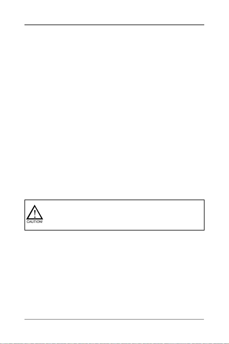
MOTHERBOARD LA YOUT
The following diagram shows the relative positions of the jumpers, connectors, major components and memory banks on the Sapphire motherboard.
PKE;;9$Wsgoix
R
R
S
G
\
S
J
w
v
s
x
g
i
r
w
r
v
s
s
x
G
$
g
F
i
W
r
r
Y
s
G
$
R
E
P
$
*
$
F
W
Y
I
Z
S
Q
I
V
WEX E8 0$WEXE70$WEXE60$WEXE5
H91ZGGcPIH
H:19ZWFcPIH
NOTE :1) Be sure to check the HDD cable orientation in order to match the colored strip to the
pin 1 end of the connector.
2) When you start up the system, please wait for 5 seconds after you power on AC.
3) Adding a metal spaced plate to the back of the Socket 775 is not recommended as
this will short motherboard components and damage the system.
PC-I7RD400 User’s Manual
Page 9
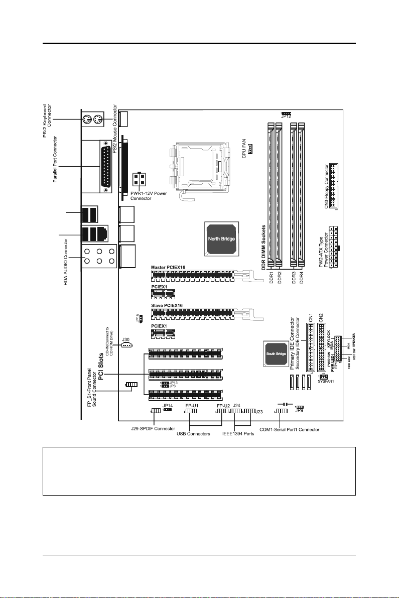
REAR P ANEL
The back panel provides the following connectors:
'
PS/2 Mouse Connector
The Sapphire motherboard provides a standard PS/2
mouse mini DIN connector for attaching a PS/2 mouse. You can plug a PS/2 mouse directly into
this connector.
PS/2 Keyboard Connector
The Sapphire motherboard provides a standard PS/2 keyboard mini DIN connector for attaching a PS/2
keyboard. Y ou can plug a PS/2 keyboard directly into
this connector.
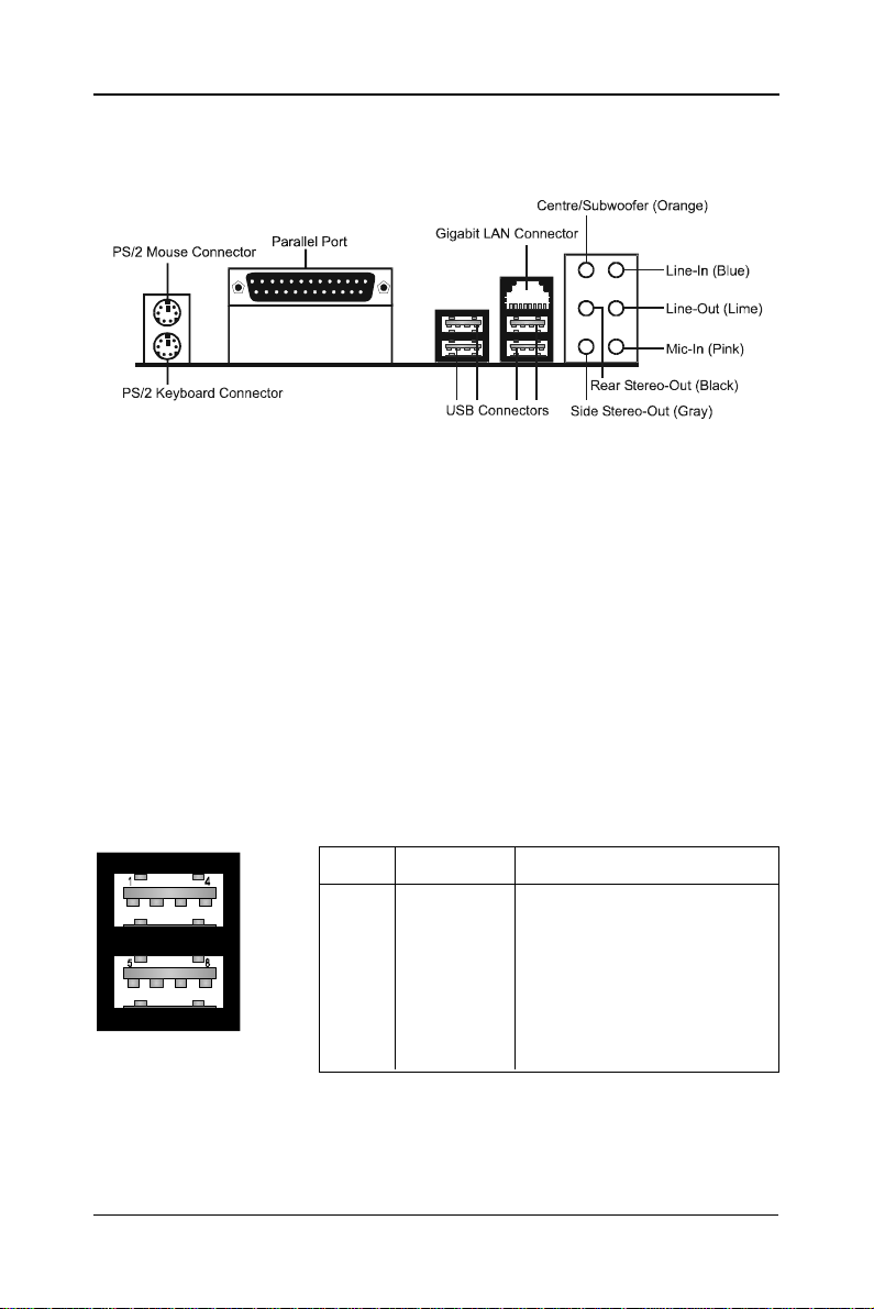
USB 2.0 Connector
The Sapphire motherboard provides an OHCI (Open Host Controller Interface) Universal Serial Bus root for attaching USB devices such as keyboard,
mouse or other USB-compatible devices. You can plug the USB device directly
into the connector.
USB 2.0 Connector USB 2.0 - Pin Definition
P IN SIGNAL DESCRIPTION
1 VCC +5V/5VSB (optional)
2 -Data 0 Negative Data Channel 0
3 +Data0 Positive Data Channel 0
4 GND Ground
5 VCC +5V/5VSB (optional)
6 -Data 1 Negative Data Channel 1
7 +Data 1 Positive Data Channel 1
8 GND Ground
SAPPHIRE PURE CROSSFIRE II
Page 10

LAN Connector
The Sapphire motherboard provides one standard RJ-45 jack for connecting
to a LocalArea Network (LAN). You can connect the network cable to the LAN
jack.
Gigabit LAN
The onboard Marvell 88E8052 PCI-E X1 controller supports 10/100/1000
Mb/s operations.
8 Channel HD Audio
Option select of 2, 6, or 8 channel audio from onboard ALC880 High
Definition audio compliant CODEC with 20-bit ADC and 24-bit DAC resolution.
- Supports CD-In, SPDIF-in and SPDIF-out.
- Optical & Coaxial SPDIF-out available on rear panel.
- Supports jack detection for easy audio device installation.
Rear panel audio jacks configuration:
Audio Jack Color 2 Channel 6 Channel 8 Channel
Blue Line-In Line-In Line-In
Lime Line-Out Front Stereo-Out Front Stereo-Out
Pink Mic-In Mic-In Mic-In
Gray -- -- Side Stereo-Out
Black -- Rear Stereo-Out Rear Stereo-Out
Orange -- Centre & Subwoofer Centre & Subwoofer
PC-I7RD400 User’s Manual
Page 11
CONNECTORS AND HEADERS
The Sapphire motherboard provides connectors to connect to the FDD, IDE
HDD, USB Ports and to the CPU/System FAN etc.
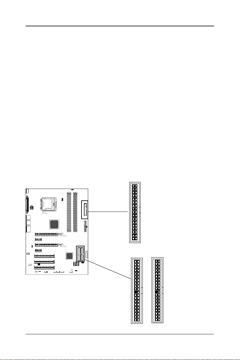
Floppy Disk Drive Connector - CN3
The Sapphire motherboard provides a standard floppy disk drive connector
that supports 1.44M, 2.88M floppy disk types.
IDE Connectors - CN1&CN2
The Sapphire motherboard has a 32-bit Enhanced PCI IDE and Ultra DMA 33/
66/100/133 controller that provides PIO mode 0~4, Bus Master, and Ultra DMA
33/66/100/133 function. Y ou can connect up to four hard disk drives, CD-ROMs,
120MB Floppy (reserved for future BIOS) and other devices.
Primary IDE Connector - CN1
The first hard drive should always be connected to CN1. CN1 can connect a
Master and a Slave drive. You must configure the second hard drive to Slave
mode by setting the jumper accordingly.
Secondary IDE Connector - CN2
CN2 can also connect a Master and a Slave drive.
CN3
R
R
I
Z
S
S
G
Q
I
\
V
S
J
1
CN1
1
SAPPHIRE PURE CROSSFIRE II
CN2
1
Page 12
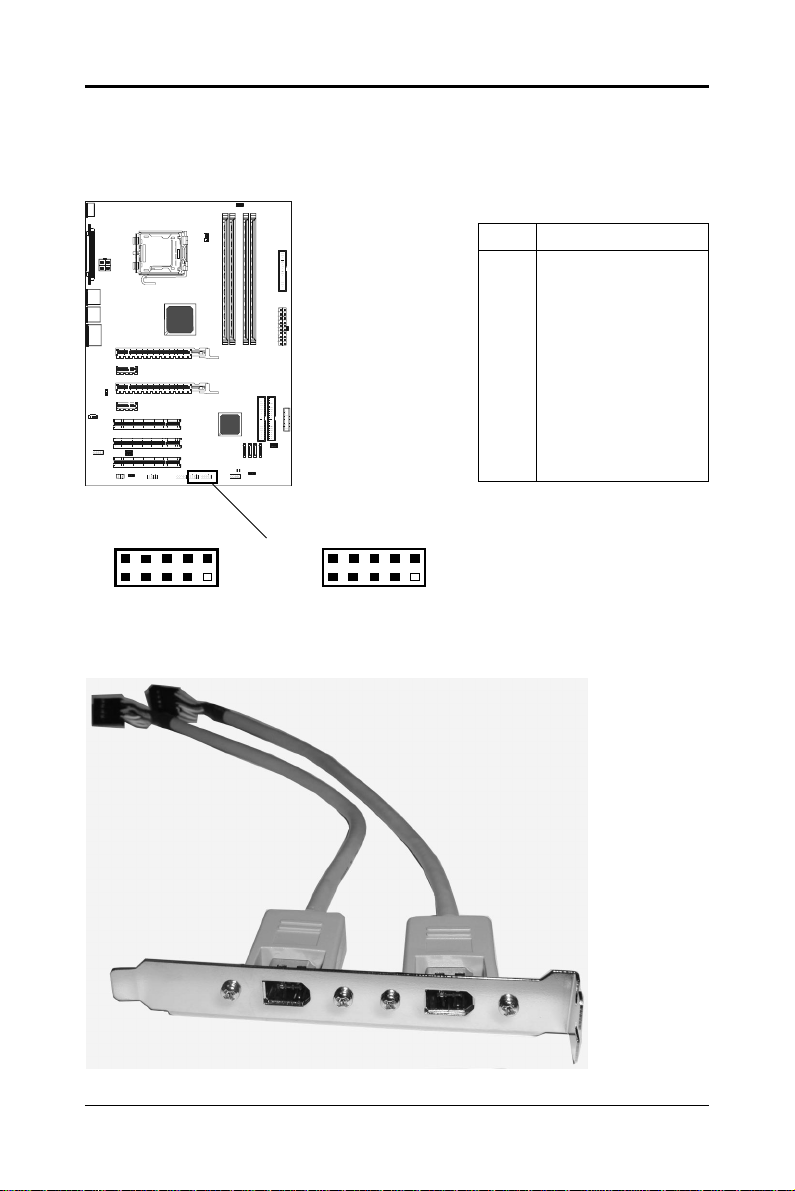
IEEE 1394 Header - J23,J24
The Sapphire motherboard provides four 1394 pin headers that allow you to
connect IEEE 1394 ports.
J24/J23 - Pin Definition
R
R
I
Z
S
S
G
Q
I
\
V
S
J
PIN SIGNAL
1TPA+
2TPA3 Ground
4 Ground
5 TPB+
6 TPB7 Cable power
8 Cable power
9 Key (no pin)
10 Ground
J24
2
1
IEEE 1394 Cable
10
9
J23
2
1
10
9
PC-I7RD400 User’s Manual
Page 13
!
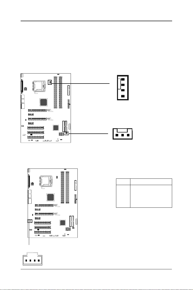
Fan Power Header - CPUFAN, SYSF AN
The CPUFAN1 (processor fan) and SYSFAN1 (system fan) support system
cooling fans using +12V via a four/three-pin head connector. When connecting
the wire to the connectors, always take note that the red wire is the positive and
should be connected to the +12V, the black wire is Ground and should be
connected to GND. If the mainboard has a System Hardware Monitor chipset
on-board, you must use a specially designed fan with speed sensor to take
advantage of the CPU fan control.
R
R
I
Z
S
S
G
Q
I
\
V
S
J
CPU FAN
SYS FAN
1
CD-IN Header - J30
This header allows for the connection of audio from CD-ROM drive.
J30
R
R
I
Z
S
S
G
Q
I
\
V
S
J
PIN SIGNAL
1 CD-L
2 GND
3 GND
4 CD-R
1
SAPPHIRE PURE CROSSFIRE II
J30 - Pin Definition
Page 14
"
Front Panel Audio Header - FP-S1
FP-S1
R
R
I
Z
S
S
G
Q
I
\
V
S
J
2
1
10
9
FP-S1 - Pin Definition
Pin Signal Description
1 PORT 1L Analog Port1 - Left channel
2 GND Ground
3 PORT 1R Analog Port 1 - Right channel
4 PRESENCE Active low signal - signals BIOS that a
High Definition Audio dongle is connected to
the analog header. PRESENCE=0 when a
High Definition Audio dongle is connected.
5 PORT 2R Analog Port 2 - Right channel
6 SENSE1_RETIRN Jack detection return from front panel JACK1
7 SENSE_SEND Jack detection sense line from the High
Definition Audio Codec jack detection
resistor network
8 KEY Connector Key
9 PORT 2L Analog Port2 - Left channel
10 SENSE2_RETIRN Jack detection return from front panel JACK2
Note: In order to utilize the front audio header, your chassis must have a
front audio connector. Also please make sure the pin assignment on the
cable is the same as the pin assignment on the motherboard header. To
find out if the chassis you are buying supports front audio connection,
please contact your dealer.
PC-I7RD400 User’s Manual
Page 15
#
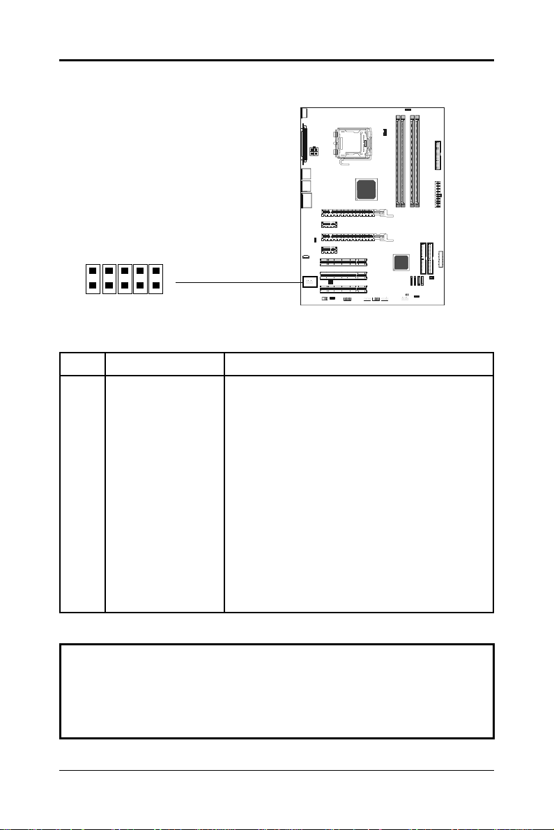
USB Header - FP-U1, FP-U2
This Sapphire motherboard has up to eight USB ports. Some computer cases
have a special module that mounts USB ports at the front of the case. If you
have this kind of case, use the auxiliary USB connector FP-U1/FP-U2 to connect the front mounted ports to the motherboard.
FP-U1, FP-U2 - Pin Definition
R
R
I
Z
S
S
G
Q
I
\
V
S
J
PIN SIGNAL
1 VCC
2 VCC
3 USBP04 USBP15 USBP0+
6 USBP1+
7 GND
8 GND
9 KEY
10 OC#
2
1
FP-U1
10
9
FP-U2
2
1
10
9
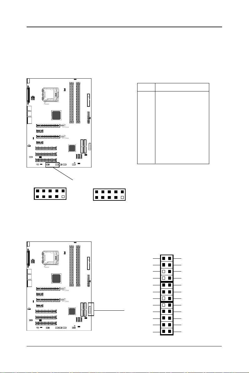
Front Panel Header - FP1
The Sapphire motherboard provides a front panel connector for the front panel
switches and LEDs. FP1 is compliant with the Front Panel I/O Connectivity
Design Guide.
FP1
R
R
I
Z
S
S
G
Q
I
\
V
S
J
KEYLOCK
PWR_SW
PW_LED-
PW_LED+
GND
KEY
KEY
IRRX
GND
KEY
KEY
GND
24 23
22 21
20
19
1718
16
14
12
10
8
6
4
2
15
13
11
9
7
5
3
1
VCC
GND
NC
SPEAKER
IRTX
VCC
NC
NC
RESET
GND
HDD_LEDHDD_LED+
SAPPHIRE PURE CROSSFIRE II
Page 16
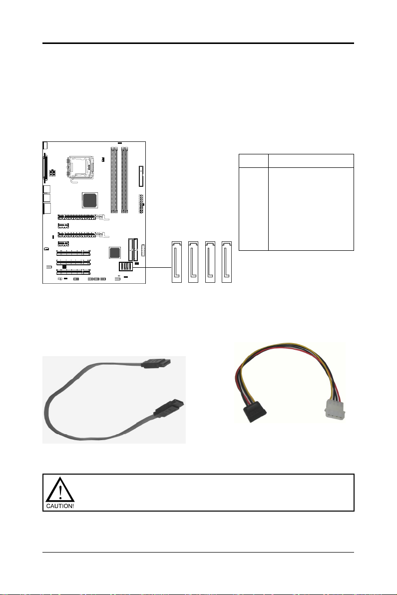
$
Serial AT A Hard Disk Connectors - SA T A1, SA T A2, SA T A3, SA T A4
The Sapphire motherboard has four SA TA connectors: SATA1, SA TA2, SATA3,
SATA4. Each supports 1
tors are fully compliant with Serial A T A 1.0 specifications. Each SA TA connector
can connect to one hard disk device. Please refer to SATA Raid Setup for
details on software installation procedure.
R
R
I
Z
S
S
G
Q
I
\
V
S
J
Serial AT A Cable
This cable is compatible for use with SATA devices.
st
generation SATA data rates of 150 MB/s. All connec-
SAT A1, SA T A2, SA TA3,
SAT A4 - Pin Definition
PIN SIGNAL
1 GND
2 TXP
3 TXN
4 GND
5 RXN
SATA4
SATA3
SATA2
6 RXP
SATA1
7 GND
Serial AT A Cable
Please do not fold the serial ATA cable at a 90 degree angle as this
will cause a loss of data during the transmission.
PC-I7RD400 User’s Manual
Serial A T A Devices
Power Cable (optional)
Page 17
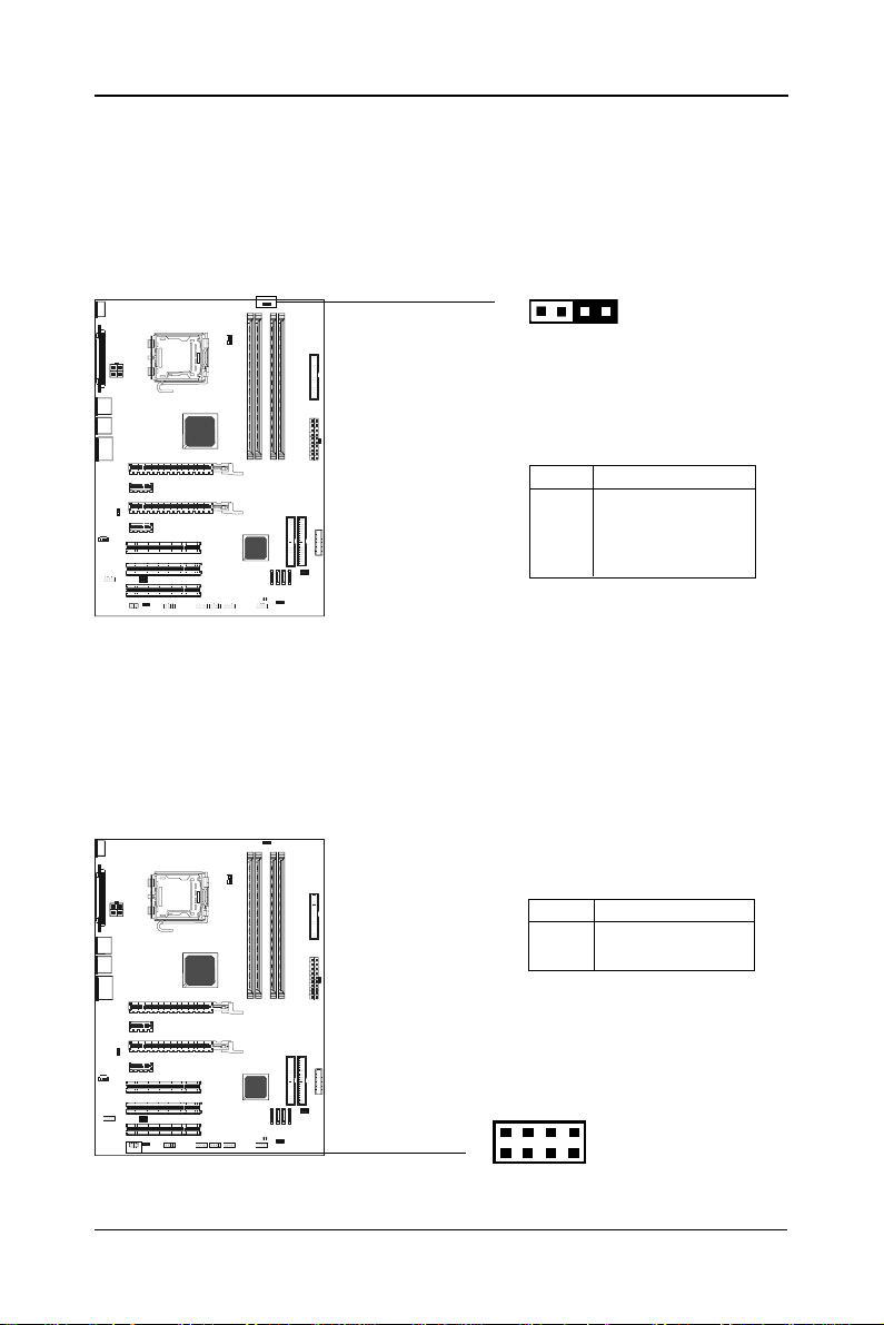
%
Chassis Alarm Lead - JP12 (optional)
This lead is for a chassis designed with an intrusion detection feature. This
requires an external detection mechanism such as a chassis intrusion sensor or microswitch. When you remove any chassis component, the sensor
triggers and sends a high-level signal to this lead to record a chassis
intrusion event.
JP12
1
R
R
I
Z
S
S
G
Q
I
\
V
S
J
JP12 - Pin Definition
PIN Assignment
1 +5VSB
2 KEY
3 Chassis Signal
4 GND
Note:
If you want to use “Chassis Alarm” Connector, you must remove 3-4 jumper .
SPDIF Header - J29
This header provides a SPDIF (Sony/Philips Digital Interface) output to digital
multimedia device through fiber or coaxial connector.
R
R
I
Z
S
S
G
Q
I
\
V
S
J
J29 - Pin Definition
PIN Assignment
1 SPDIF_OUTX
2 SPDIF_INX
J29
2
1
8
7
SAPPHIRE PURE CROSSFIRE II
Page 18

&
Power LED: D5/D6 (optional)
The green LED lights when the system is in the power-on state.
The red LED lights whenever AC power is attached, irrespective of whether the
system is powered-on, powered-off or in standby mode.
R
R
I
Z
S
S
G
Q
I
\
V
S
J
D5-VCC_LED (Green)
D6-5VSB_LED (Red)
PC-I7RD400 User’s Manual
Page 19

'
JUMPER SETTING
The Sapphire motherboard provides jumpers for enabling the configuration of
the motherboard’s hardware.
R
R
I
Z
S
S
G
Q
I
\
V
S
J
JP15
1
1
JP3
1
JP14
Clear CMOS Jumper - JP9
If you want to clear the system configuration, use the JP9 (Clear CMOS Jumper)
to clear data.
JP9 Selection
1-2* Normal*
2-3 CMOS Clear
JP9
1
JP14-Onboard AC97 Sound Select
JP14 Function
1-2* AC97 Sound Enable*
2-3 AC97 Sound Disable
JP3-Onboard IEEE1394 Select
JP3 Selection
1-2* IEEE1394 Enable*
2-3 IEEE1394 Disable
JP15-Onboard Gigabit LAN Select
JP15 Function
1-2* Gigabit LAN Enable*
2-3 Gigabit LAN Disable
Close Open * = Default setting.
SAPPHIRE PURE CROSSFIRE II
Page 20

SLOTS
The Sapphire motherboard provides two PCI-E x16 slots, two PCI-E x1 slot
and three 32-bit PCI slots.
R
R
I
Z
S
S
G
Q
I
\
V
S
J
Master PCI-E X16 Slot
PCI-E X1 Slot
Slave PCI-E X16 Slot
PCI-E X1 Slot
PCI Slots
PCI Express x16 Graphics Interface
• Two 16-lane (x16 port) PCI Express graphics ports, fully compliant
with the PCI Express Base Specification revision 1.0a.
• A base PCI Express frequency of 4GB/s.
• PCI Express supported enhanced addressing mechanism.
• Supports ATI CrossFire (optional).
Note: This Sapphire motherboard is bundled with a PCI-E x16 Adapter. If
you want to use one PCI-Ex16 graphic card only, please insert the
bundled PCI-E x16 Adapter into the Slave PCI-E x16 slot simultaneously.
PCI Express x1 Ports
• Fully compliant to the PCI Express Base Specification revision 1.0a.
• Two virtual channel support for full unsynchronized data transfers.
• Supports full 2.5Gb/s bandwidth in each direction per x1 lane.
PCI (Peripheral Component Interconnect) Slots
• Three 32-bit PCI ports for add-in card connections.
PC-I7RD400 User’s Manual
Page 21

CPU INST ALLATION
Please follow the steps below to install the CPU.
1.Please turn off the power and unplug the power cord before installing the CPU. Use index finger and
thumb to raise the metal lever so it
is separated from the bottom steel
shell grip hook.
2.Use index finger to lift the top steel
shell.
3.Use index finger and thumb to
place the CPU onto the socket
(Look for the gold arrow. The gold
arrow should point towards the lever pivot).
SAPPHIRE PURE CROSSFIRE II
Page 22

4.Use index finger and thumb to
press down the metal lever.The cap
will be pushed up by the CPU. This
may also be done by removing the
lid beforehand.
5. Press the metal lever so it is secured in the bottom steel shell
grip hook.
6. It’s recommended that the CPU heatsink be approved by Intel for use with
the Prescott CPU. Choose the orientation of the thermal solution for optimal
wire routing to the fan header on the motherboard, Position the thermal solution over the processor. Ensure the fan wiring is positioned to prevent wire
pinching between the heatsink and the processor, or between the heatsink
clip and the socket.
PC-I7RD400 User’s Manual
Page 23

7. Align the fastener tips with the
motherboard hole pattern, insert the
fastener tips into the holes, guiding
the wires to avoid pinching. the fasteners will slide through the Sapphire motherboard holes without
applying too much force.
8. Engage the fasteners caps. Apply thumb pressure to the top of
each of the 4 fastener caps, there
is no specific order of engagement,
you will hear a “click” upon full
engagement.
9. Gently rotate the cap clockwise
1/4 turn to fasten the heatsink onto
the Sapphire motherboard.
!
10. Lastly, attach the fan wire
connector to the 4 pin fan header
connector on the Sapphire
motherboard labeled CPU FAN.
SAPPHIRE PURE CROSSFIRE II
Page 24

"
MEMORY CONFIGURATIONS
Install DDR DIMMs
Please follow steps below to install DDR DIMMs.
1. Hold the DDR DIMM module by the edges and remove it from its antistatic
package.
2. Make sure the clips at either end of the DIMM socket are pushed away from
thesocket.
Clip
DDR DIMM Socket
Notch
3. Position the DDR DIMM module above the socket and align the notch in
thebottom edge of the module with the key in the socket.
4. Insert the bottom edge of the DDR DIMM module into the socket.
5. When the module is seated, press down on the top edge of the DDR
DIMM module until the retaining clips at the ends of the socket snap into
place.
Note: Please turn the system off before installing or removing any device,
otherwise system damage can occur.
Memory Configurations
Please refer to the following recommended memory configurations.
Mode / (DIMM Type) Case Sockets
DDR1 DDR2 DDR3 DDR4
Single-channel / 1* Populated ---- ---- ----
(DDR400/DDR333/DDR266) 2* ---- Populated ---- ----
3* ---- ---- Populated ---4* ---- ---- ---- Populated
DDR DIMM
Clip
Dual-channel / 1# Populated ---- Populated ----
(DDR400/DDR333/DDR266) 2 # ---- Populated ---- Populated
3# Populated Populated Populated Populated
Note: • In dual channel mode, always install an identical (the same type
and size) DDR DIMM pair in sockets.
• It is not recommended to use a three DIMM configuration.
• Memory channel speed is determined by slowest DIMM populated
in system.
PC-I7RD400 User’s Manual
Page 25

#
CrossFire SETUP
If you want to set up the CrossFire, the Master card should be inserted into the
Master slot and the Slave card should be inserted into the Slave slot properly.
Make sure that the card is inserted in correct slot.
Enter CMOS Setup Utility to set CrossFire
1. Press <Del> Key during POST.
2. Scroll to “Advance Chipset Features”, press enter.
3. Scroll to “Adjust PCIE Confg.”, press enter again.
4. Set “PCIE GFX TWO PORT” to “Enable”, and the “GFX Link Width” to “x8”.
5. Press F10 to Save and Exit.
Installing Driver
After setting up the Windows, you need to install the 8.15 driver or later which
must include the Catalyst Control Centre (CCC).
Step1
SAPPHIRE PURE CROSSFIRE II
Page 26

$
In the CCC advanced mode, you need to click the check box to enable the
CrossFire.
Step 2
Click “Standard View” as default
Click “CrossFire
TM
”
Step3
Select the check box
Step4
After CrossFire is enabled successfully, you will be able to see that CrossFire
has started.
PC-I7RD400 User’s Manual
Page 27

%
SA TA RAID SETUP
Creating and deleting RAID sets is a function found in the RAID utility. During
bootup, the following message will appear, pausing for a few seconds to allow
the user to enter the RAID utility:
Press Ctrl+S or F4 to enter RAID utility
An easy-to-use screen will appear with the following choices:
Create RAID Set Delete RAID Set Rebuild RAID Set Resolve Conflicts
Below this will be a list of drives currently installed on the system.
Creating RAID Sets
SATA Raid supports two drives. Please follow the below mentioned steps.
1. Select “Create RAID Set” and choose either a “Striped” or “Mirrored” RAID Set.
2. Select if you want the utility to Auto Configure the RAID Set or if you want to manually
configure the RAID Set. For Striped Sets, you can change the chunk size. For
Mirrored Sets, you can assign Source and Target drives, as well as if you
want Disk Copy.
What is a Striped RAID Set? Also known as RAID Level O, a Striped RAID Set allows
for high speed storage without redundancy. This requires 2 identical drives allowing for
data to be split across the drives resulting in faster data throughput. Choose this
selection if you want to gain performance.
What is a Mirrored RAID Set? Also known as RAID Level 1, a Mirrored RAID Set
allows for both high speed storage and redundancy. This requires 2 identical drives
allowing for data to be copied from a source drive and duplicated onto the second drive.
Choose this selection if you prefer security options to prevent data loss.
What is a Disk Copy? In the case where you have a drive that already contains data
and you would like to create a new RAID Set, you will need to purchase an identical
drive and select Disk Copy to allow the contents of your source drive to be copied to
your new destination drive.
Deleting RAID Sets
1. To remove one or more RAID sets, select “Delete RAID Set.”
2. Select desired set and press Y when asked “Are You Sure?”
Rebuilding RAID Sets
In case your RAID set has encountered an error or it has been changed, you can
recover the RAID set using this option.
SAPPHIRE PURE CROSSFIRE II
Page 28

&
Resolving Conflicts
When a RAID set is created, the metadata written to the disk includes drive
connection information (Primary Channel, Secondary Channel). If, after a disk
failure, the replacement disk was previously part of a RAID set (or used in
another system), it may have conflicting metadata, specifically in reference to
the drive connection information. If so, this will prohibit the RAID set from being
either created or rebuilt. In order for the RAID set to function properly, this old
metadata must be first overwritten with the new metadata. To resolve this,
select “Resolve Conflict” and the correct metadata, including the correct drive
connection information, will be written to the replacement disk.
Driver and RAID Software Installation
1. For Windows 2000 and XP, after Windows has finished booting up, the
system will automatically find the newly installed adapter and prompt the
Found New Hardware Wizard window. Click Cancel to skip it.
2. Insert the bundled driver CD DISC into your CD-ROM drive, select “ATI
Chipset\ATI_Raid Driver” installation bar on the dialogue Window to begin
the driver and software installation. (Please follow the instructions to finish the
installation).
Install Windows 2000/XP
a. Insert the bundled driver CD DISC into CD-ROM (G:). Copy all files
from the directory ( G:\ATI chipset\ATI_Raid ) to a floppy disk.
b. Install the OS from CD-ROM.
c. Press “F6” at the prompt “Press F6 if you need to install a third party
SCSI or RAID driver...”.
d. Insert the floppy disk.
e. Choose the OS device driver to be loaded.
f. Install the OS.
g. Install the driver after OS is installed.
PC-I7RD400 User’s Manual
Page 29

'
BIOS SETUP
About the Setup Utility
The mainboard uses the latest Award BIOS with support for Windows Plug
and Play. The CMOS chip on the motherboard contains the ROM setup instructions for configuring the motherboard BIOS.
The BIOS (Basic Input and Output System) Setup Utility displays the system’s
configuration status and provides you with options to set system parameters.
The parameters are stored in battery-backed-up CMOS RAM that saves this
information when the power is turned off. When the system is turned back on,
the system is configured with the values you stored in CMOS.
The BIOS Setup Utility enables you to configure:
Hard drives, diskette drives and peripherals
Video display type and display options
Password protection to prevent unauthorized use
Power Management features
Overclocking features
The settings made in the Setup Utility affect how the computer performs.
Before using the Setup Utility, ensure that you understand the Setup Utility
options.
This chapter provides explanations for Setup Utility options.
The Standard Configuration
A standard configuration has already been set in the Setup Utility. However, we
recommend that you read this chapter in case you need to make any changes
in the future.
This Setup Utility should be used:
- when changing the system configuration
- when a configuration error is detected and you are prompted to make
changes to the Setup Utility
- when trying to resolve IRQ conflicts
- when making changes to the Power Management configuration
- when changing the password or making other changes to the Security
Setup
Entering the Setup Utility
When you power on the system, BIOS enters the Power-On Self Test (POST)
routines. POST is a series of built-in diagnostics performed by the BIOS. After
the POST routines are completed, the following message appears:
SAPPHIRE PURE CROSSFIRE II
Page 30

!
Press DEL to enter SETUP
Pressing the delete key accesses the BIOS Setup Utility:
Phoenix - Award WorkstationBIOS CMOS Setup Utility
T Standard CMOS Features
T Advanced BIOS Features
T Advanced Chipset Features
T Integrated Peripherals
T Power Management Setup
T PnP/PCI Configurations
T PC Health Status
Esc: Quit : \[: Select Item
F10: Save & Exit Setup
Time, Date, Hard Disk Type...
(Note : The sample BIOS Setup Menu included here only shows a typical
case, and may not be exactly the same as the one on your unit.)
BIOS Navigation Keys
The BIOS navigation keys are listed below:
KEY FUNCTION
\[ Move
Enter Select item or option
+/-/PU/PD Value
ESC Exit
F1 Display the General Help
F5 Restore the Previous Values
F6 Load the Fail-Safe Defaults
F7 Load the Optimized Defaults
F10 Save configuration
T Frequency/Voltage Control
Load Fail-Safe Defaults
Load Optimized Defaults
Set Supervisor Password
Set User Password
Save & Exit Setup
Exit Without Saving
Updating the BIOS
You can download and install updated BIOS for this motherboard from
manufacture’s web site. New BIOS provides support for new peripherals,
improvements in performance, or fixes for known bugs. Install new BIOS as
follows:
1. Create a bootable system disk. (Refer to Windows online help for
information on creating a bootable system disk.)
2. Download the Flash Utility and new BIOS file from the manufacturer’s Web
site. Copy these files to the system diskette you created in Step 1.
3. Turn off your computer and insert the system diskette in your computer’s
diskette drive. (You might need to run the Setup Utility and change the boot
priority items on the Advanced BIOS Features Setup page, to force your
computer to boot from the floppy diskette drive first.) Also see page 54 for
more information.
4. At the A:\ prompt, type the Flash Utility program name and press <Enter>.
PC-I7RD400 User’s Manual
Page 31

!
5. Type the file name of the new BIOS in the “File Name to Program” text box.
Follow the onscreen directions to update the motherboard BIOS.
6. When the installation is complete, remove the floppy diskette from the dis
kette drive and restart your computer. If your motherboard has a Flash BIOS
jumper, reset the jumper to protect the newly installed BIOS from being
overwritten.
Using BIOS
When you start the Setup Utility, the main menu appears. The main menu of
the Setup Utility displays a list of the options that are available. A highlight
indicates which option is currently selected. Use the cursor arrow keys to
move the highlight to other options. When an option is highlighted, execute the
option by pressing <Enter>.
Some options lead to pop-up dialog boxes that prompt you to verify that you
wish to execute the option. Other options lead to dialog boxes that prompt you
for information.
Some options (marked with a triangle
change the values for the option. Use the cursor arrow keys to move the items
in the submenu.
In this manual, default values are enclosed in parenthesis. Submenu items
are denoted by a triangle
T .
Standard CMOS Features
This option displays basic information about your system.
T) lead to submenus that enable you to
Phoenix - Award WorkstationBIOS CMOS Setup Utility
Standard CMOS Features
Date (mm:dd:yy) Sun, July 10 2005
Time (hh:mm:ss) 23 : 21 : 34 Item Help
T IDE Channel 0 Master [ST380021A] Menu Level T
T IDE Channel 0 Slave [None] Change the day, month,
T IDE Channel 1 Master [SAMSUNG DVD-ROM SD-6] year and century
T IDE Channel 1 Slave [GCR-8525B]
T IDE Channel 2 Master [None]
T IDE Channel 3 Master [None]
T IDE Channel 4 Master [None]
T IDE Channel 5 Master [None]
Drive A [1.44M, 3.5 in.]
Halt On [All Errors]
Base Memory 640K
Extended Memory 260096K
Total Memory 261120K
\[: Move Enter: Select +/-/PU/PD: Value F10: Save ESC: Exit F1: General Help
F5: Previous Values F6:Fail-Safe Defaults F7: Optimized Defaults
SAPPHIRE PURE CROSSFIRE II
Page 32

!
Date and Time
The Date and Time shows the current date and time on the computer . If you are
running Windows, it is automatically updated whenever you make changes to
the Windows Date and Time Properties utility.
IDE Devices (None)
Your computer has two IDE channels (Primary and Secondary) and each
channel can be installed with one or two devices (Master and Slave). Use
these items to configure each device on the IDE channel.
Press <Enter> to display the IDE submenu:
Phoenix - Award WorkstationBIOS CMOS Setup Utility
IDE HDD Auto-Detection [Press Enter] Item Help
IDE Channel 0 Master [Auto] Menu Level TT
Access Mode [Auto]
Capacity 0MB HDD’s size, head… on
Cylinder 0
Head 0
Precomp 0
Lading Zone 0
Sector 0
\[: Move Enter: Select +/-/PU/PD: Value F10: Save ESC: Exit F1: General Help
F5: Previous Values F6:Fail-Safe Defaults F7: Optimized Defaults
IDE Channel 0 Master
To auto-detect the
this channel
IDE HDD Auto-Detection
Press <Enter> while this option is highlighted to prompt the Setup Utility to
automatically detect and configure an IDE device on the IDE channel.
NOTE: If you are setting up a new hard disk drive that supports LBA mode,
more than one line will appear in the parameter box. Choose the line
that lists LBA for the LBA drive.
IDE Channel 0/1 Master/Slave (Auto)
Leave this option at Auto to enable the system to automatically detect and
configure IDE devices on the channel. If it fails to find a device, change the
value to Manual and then manually configure the drive by entering the
characteristics of the drive in the items described below. Refer to your drive’s
documentation or look on the drive casing if you need to obtain this
information. If no device is installed, change the value to None.
NOTE: Before attempting to configure a hard disk drive, ensure that you have
the configuration information supplied by the manufacturer of your hard
drive. Incorrect settings can result in your system not recognizing the
installed hard disk.
PC-I7RD400 User’s Manual
Page 33

!!
Access Mode (Auto)
This option defines ways that can be used to access IDE hard disks such as
LBA (Large Block Addressing). Leave this value at Auto and the system will
automatically decide the fastest way to access the hard disk drive.
Press <Esc> to return to the Standard CMOS Features Page
Drive A (1.44M, 3.5 in./None)
This option defines the characteristics of any diskette drive attached to the
system. You can connect one or two diskette drives.
Halt On (All Errors)
This option defines the operation of the system POST (Power On Self Test)
routine. You can use this item to select which types of errors in the POST are
sufficient for you to halt the system.
Base Memory, Extended Memory , and Total Memory
These options are automatically detected by the system at startup. They are
display-only fields. You cannot make changes to these fields.
Advanced BIOS Features
This section defines advanced information about your system.
Phoenix - Award WorkstationBIOS CMOS Setup Utility
T CPU Feature [Press Enter]
T Hard Disk Boot Priority [Press Enter]
Virus Warning [Disabled]
CPU L1 & L2 Cache [Enabled]
Hyper-Treading Technology [Enabled]
Quick Power On Self Test [Enabled]
First Boot Device [Floppy]
Second Boot Device [Hard Disk]
Third Boot Device [LS120]
Boot Other Device [Enabled]
Boot Up Floppy Seek [Enabled]
Boot Up NumLock Status [On]
Gate A20 Option [Fast]
Typematic Rate Setting [Disabled]
x Typematic Rate (Chars/Sec) 6
x Typematic Delay (Msec) 250
Security Option [Setup]
APIC Mode [Enabled]
MPS Version Control For OS [1.4]
\[: Move Enter: Select +/-/PU/PD: Value F10: Save ESC: Exit F1: General Help
F5: Previous Values F6:Fail-Safe Defaults F7: Optimized Defaults
Advanced BIOS Features
Item Help
Menu Level T
SAPPHIRE PURE CROSSFIRE II
Page 34

!"
Hard Disk Boot Priority
Navigate to this section and press <Enter> to view the following screen:
Phoenix - Award WorkstationBIOS CMOS Setup Utility
1. Ch0 M. : ST380021A Item Help
2. Bootable Add-in Cards
\[: Move Enter: Select +/-/PU/PD: Value F10: Save ESC: Exit F1: General Help
F5: Previous Values F6:Fail-Safe Defaults F7: Optimized Defaults
Virus Warning (Disabled)
If this function is enabled and someone attempts to write data into this area,
BIOS will show a warning message on screen and an alarm will beep.
CPU L1&L2 Cache (Enabled)
All processors that can be installed in this motherboard use L1&L2 cache
memory to improve performance. Leave this item at the default value for better
performance.
Quick Power On Self T est (Enabled)
To allow the system to skip certain tests while booting. This will decrease the
time needed to boot the system. You might like to enable this option when you
are confident that your system hardware is operating smoothly.
Hard Disk Boot Priority
Menu Level TT
Use <
> or <> to
select a device, then
press <+> to move it
up, or <-> to move it
down the list. Press
<ESC> to exit this
menu.
Third Boot Device (LS120)
Use these three options to select the priority and order of the devices that your
system searches for an operating system at start-up time.
Boot Other Device (Enabled)
When this option enabled, the system searches all other possible locations
for an operating system if it fails to find one in the devices specified among the
First, Second, and Third boot devices.
Boot Up Floppy Seek (Enabled)
When this option is enabled, it checks the size of the floppy disk drives at
start-up time.
PC-I7RD400 User’s Manual
Page 35

!#
Boot Up Num Lock Status (On)
This option defines if the keyboard Num Lock key is active when your system
is started, default is on.
Gate A20 Option (Fast)
This option defines how the system handles legacy software that was written
for an earlier generation of processors.
Typematic Rate Setting (Disabled)
If this option is enabled, you can use the following two options to set the
typematic rate and the typematic delay settings for your keyboard.
- Typematic Rate (Chars/Sec):
This option defines how many characters per second are generated by
a held-down key.
- Typematic Delay (Msec):
This option defines how many milliseconds must elapse before a
held-down key begins generating repeat characters.
Security Option (Setup)
If you have installed password protection, this option defines if the password
is required at system start up or if it is only required when a user tries to enter
the Setup Utility.
APIC Mode (Enabled)
This option allows you to enable or disable the APIC (Advanced
Programmable Interrupt Controller) mode. APIC provides symmetric
multiprocessing (SMP) for systems, allowing support for up to 60 processors.
It is recommended that this option be enabled.
MPS Version Control For OS (1.4)
This option can improve support for multiple PCI bus configurations and improve future expendability. The default is 1.4.
Advanced Chipset Features
These options define critical timing parameters of the Sapphire motherboard.
You should leave the options on this page at their default values unless you
are familiar with the technical specification of your system hardware. Changing the values to a incorrect setting may result in fatal errors or may cause your
system to run unstable.
SAPPHIRE PURE CROSSFIRE II
Page 36

!$
Phoenix - Award WorkstationBIOS CMOS Setup Utility
Current MRC Version 5.2 Item Help
Memory Frequency For [AUTO]
UMA Frame Buffer Size [64MB] Menu Level T
T Adjust DRAM Timing [Press Enter]
T Adjust PCIE Confg. [Press Enter]
Video Display Devices [Auto]
Tv Standard [NTSC]
Memory Hole [Disabled]
System BIOS Cacheable [Disabled]
Multi-Function [Disabled]
\[: Move Enter: Select +/-/PU/PD: Value F10: Save ESC: Exit F1: General Help
F5: Previous Values F6:Fail-Safe Defaults F7: Optimized Defaults
Advanced Chipset Features
Integrated Peripherals
This section displays options that define the operation of peripheral
components on the system’s input/output ports.
Phoenix - Award WorkstationBIOS CMOS Setup Utility
T South OnChip IDE Device [Press Enter] Item Help
T South OnChip PCI Device [Press Enter]
Init Display First [PCIEx] Menu Level T
X Surroundview [Disabled]
USB EHCI Controller [Enabled]
OnChip USB Controller [Enabled]
USB Legacy Support [Disabled]
USB Mouse Support [Disabled]
IDE HDD Block Mode [Enabled]
POWER ON Function [BUTTON ONLY]
X KB Power On Password Enter
X Hot Key Power ON Ctrl - F1
Onboard FDC Controller [Enabled]
Onboard Serial Port 1 [3F8/IRQ4]
Onboard Serial Port 2 [2F8/IRQ3]
UART Mode Select [IrDA]
UR2 Duplex Mode [Full]
Onboard Parallel Port [378/IRQ7]
Parallel Port Mode [ECP]
Integrated Peripherals
\[: Move Enter: Select +/-/PU/PD: Value F10: Save ESC: Exit F1: General Help
F5: Previous Values F6:Fail-Safe Defaults F7: Optimized Defaults
PC-I7RD400 User’s Manual
Page 37

South OnChip IDE Device
Navigate to this option and press <Enter> to view the following screen:
!%
Phoenix – Award WorkstationBIOS CMOS Setup Utility
IDE DMA transfer access [Enabled] Item Help
OnChip IDE Channel0 [Enabled]
OnChip IDE Channel1 [Enabled] Menu Level TT
IDE Prefetch Mode [Disabled]
Primary Master PIO [Auto]
Primary Slave PIO [Auto]
Secondary Master PIO [Auto]
Secondary Slave PIO [Auto]
Primary Master UDMA [Auto]
Primary Slave UDMA [Auto]
Secondary Master UDMA [Auto]
Secondary Slave UDMA [Auto]
\[: Move Enter: Select +/-/PU/PD: Value F10: Save ESC: Exit F1: General Help
F5: Previous Values F6:Fail-Safe Defaults F7: Optimized Defaults
South OnChip IDE Device
IDE DMA transfer access (Enabled)
This option allows you to enable the transfer access of the IDE DMA. If you
disable this function you will only have PIO modes 1-4 available.
OnChip IDE Channel 0/1 (Enabled)
Use this option to enable or disable the PCI IDE channels that are integrated
on the motherboard.
IDE Prefetch Mode (Enabled)
The onboard IDE drive interface supports IDE prefetching for faster drive
access. If you install a primary and secondary add-on interface, set this field to
Disable if the interface does not support prefetching.
Primary/Secondary Master/Slave PIO (Auto)
Each IDE channel supports a master device and a slave device. These four
items let you assign the kind of PIO (Programmed Input/Output) was used by
the IDE devices. Choose Auto to let the system auto detect which PIO mode is
best, or select a PIO mode from 0 to 4.
Primary/Secondary Master/Slave UDMA (Auto)
Each IDE channel supports a master device and a slave device. This
motherboard supports UltraDMA technology, which provides faster access to
IDE devices. If you install a device that supports UltraDMA, change the
appropriate item on this list to Auto.
SAPPHIRE PURE CROSSFIRE II
Page 38

!&
IDE HDD Block Mode (Enabled)
Enable this option if your IDE hard drive supports block mode. Block mode
enables BIOS to automatically detect the optimal number of block read and
writes per sector that the drive can support. It also improves the speed of
access to IDE devices.
Press <Esc> to return to the Standard CMOS Features Page
South OnChip PCI Device
Navigate to this option and press <Enter> to view the following screen:
Phoenix - Award WorkstationBIOS CMOS Setup Utility
Onboard Azalia Audio [Auto]
Onboard Azalia Clock [UsbClk48]
Onboard SAT A Controller [Both]
Onboard SAT A T yp e [RAID Controller]
\[: Move Enter: Select +/-/PU/PD: Value F10: Save ESC: Exit F1: General Help
F5: Previous Values F6:Fail-Safe Defaults F7: Optimized Defaults
South OnChip PCI Device
Item Help
Menu Level TT
Onboard Azalia AUDIO (Auto)
This option allows you to control the onboard Azalia (High Definition) audio.
Disable this option if you do not need the high definition onboard sound.
Onboard SA TA Controller (Both)
This option allows you to enable or disable the Serial ATA controller.
Onboard SA TA T ype (RAID Controller)
This option allows you to control the Serial ATA controller as RAID mode.
Press <Esc> to return to the Standard CMOS Features Page
Init Display First
Use this option to specify whether your graphics adapter is installed in one of
the PCI slots.
OnChip USB Controller (Enabled)
This option allows you to enable or disable the onboard USB controller.
USB Mouse Support (Disabled)
This option allows you to enable or disable the USB mouse support.
PC-I7RD400 User’s Manual
Page 39

!'
Onboard FDC Controller (Enabled)
Select Enabled if your system has a floppy drive controller (FDC) installed in
the system board and you want to use it. If you install add-in FDC or the system
has no floppy drive, select Disabled.
Onboard Serial Port 1 (3F8/IRQ4)
Select a logical COM port name and matching address for the first and second
serial ports. Select an address and corresponding interrupt for the first and
second serial ports.
Parallel Port Mode (ECP)
Select an operating mode for the onboard parallel (printer) port. Select a DMA
channel for the port when you choose ECP or ECP+EPP mode for the Parallel
Port Mode.
Power Management Setup
This option lets you control system power management. The system has
various power-saving modes including powering down the hard disk, turning
off the video, suspending to RAM, and software power down that allows the
system to be automatically resumed by certain events.
Phoenix-Award WorkstationBIOS CMOS Setup Utility
ACPI function [Enabled]
ACPI Suspend Type [S1(POS)]
C2 Disable/Enable [Disabled]
Power Management Option [User Define]
HDD Power Down [Disabled]
Doze Mode [Disabled]
Video Off Option [Suspend -> Off]
Video Off Method [V/H SYNC+Blank]
MODEM Use IRQ [3]
Soft-Off by PWRBTN [Instant-Off]
Power-on by PCI Card/LAN [Enabled]
Modem Ring Resume [Disabled]
RTC Alarm Resume [Disabled]
* Date (of Month) 0
* Resume Time (hh:mm:ss) 0 : 0 : 0
T IRQ/Event Activity Detect [Press Enter]
\[: Move Enter: Select +/-/PU/PD: Value F10: Save ESC: Exit F1: General Help
F5: Previous Values F6:Fail-Safe Defaults F7: Optimized Defaults
Power Management Setup
Item Help
Menu Level T
ACPI function (Enabled)
Select Enabled only if your computer’s operating system supports the
Advanced Configuration and Power Interface (ACPI) specification.
ACPI Suspend Type S1 (POS)
Use this item to define the suspend mode for your system.
SAPPHIRE PURE CROSSFIRE II
Page 40

"
Power Management Option (User Define)
This option allows you to select the type (or degree) of power saving for Doze,
Standby, and Suspend modes.
- User Define – Select time-out period in the section for each mode
stated below.
- Max Saving – Maximum power savings. Inactivity period is 1 minute in
each mode.
- Min Saving – Minimum power savings. Inactivity period is 1 hour in each
mode (except the hard driver)
HDD Power Down (Disabled)
The IDE hard drive will spin down if it is not accessed within a specified length
of time. Options are from 1 Min to 15 Min and Disabled.
Video Off Option (Suspend—> Off)
This option defines if the video is powered down when the system is put into
suspend mode.
Video Off Method (V/H SYNC+Blank)
This item defines how the video is powered down to save power.
MODEM Use IRQ (3)
If you want an incoming call on a modem to automatically resume the system
from a power-saving mode, use this item to specify the interrupt request line
(IRQ) that is used by the modem. You might have to connect the fax/modem to
the motherboard Wake On Modem connector for this feature to work.
Soft-Off by PWRBTN (Instant Off)
Under ACPI (Advanced Configuration and Power management Interface) you
can create a software power down. In a software power down, the system can
be resumed by Wake Up Alarms. This option lets you install a software power
down that is controlled by the power button on your system. If you select
Instant-Off, then the power button causes a software power down. If you select
Delay 4 Sec, then holding the power button down for four seconds is required
to cause a software power down.
Power-on by PCI Card/LAN (Enabled)
This options allows the system to be awakened from power saving modes
when activity or input signal of the PCI Card is detected.
RTC Alarm Resume (Disabled)
When set to Enabled, you can set the date (day of the month), hour, minute and
second to turn on your system. When set to 0 (zero) for the day of the month, the
alarm will power on your system every day at the specified time.
- Date of Month: Use this field to define the date of month when using the
RTC alarm to resume the system.
- Resume Time: Use this field to define the time when using the RTC
alarm to resume the system.
PC-I7RD400 User’s Manual
Page 41

"
PNP/PCI Configurations
This section configures how PnP (Plug and Play) and PCI expansion cards
operate in your system. The PCI bus on the motherboard uses system IRQs
(Interrupt ReQuests) and DMAs (Direct Memory Access). You must set up the
IRQ and DMA assignments correctly through the PnP/PCI Configurations Setup
utility for the motherboard to work properly. This screen appears after entering:
Phoenix-AwardBIOS CMOS Setup Utility
PnP/PCI Configurations
Reset Configuration Data [Disabled] Item Help
Resources Controlled By [Auto (ESCD)]
* IRQ Resources Press Enter
PCI/VGA Palette Snoop [Disabled]
Assign IRQ For VGA [Enabled]
Assign IRQ For USB [Enabled]
PCI Latency Timer (CLK) [ 64]
** PCI Express relative items **
Maximum Payload Size [4096]
\[: Move Enter: Select +/-/PU/PD: Value F10: Save ESC: Exit F1: General Help
F5: Previous Values F6:Fail-Safe Defaults F7: Optimized Defaults
Menu Level T
Default is Disabled.
Select Enabled to reset
Extended System
Configuration Data
ESCD) when you exit
Setup if you have
installed a new add-on
and the system
reconfiguration has
caused such a serious
conflict that the OS
cannot boot
Reset Configuration Data (Disabled)
If you enable this option and restart the system, any Plug and Play configuration data stored in the BIOS Setup is cleared from memory.
Resources Controlled By (Auto(ESCD))
You should leave this option at the default (Auto (ESCD)). When enabled, the
system dynamically allocates resources to Plug and Play devices as they are
required. If you cannot get a legacy ISA (Industry Standard Architecture)
expansion card to work properly, you might be able to solve the problem by
changing this item to Manual, and then opening up the IRQ Resources
submenu.
* IRQ Resources:
In the IRQ Resources submenu, if you assign an IRQ to Legacy, then
that Interrupt Request Line is reserved for a legacy ISA expansion card.
In the Memory Resources submenu, use the first item Reserved
memory Base to set the start address of the memory you want to re
serve for the ISA expansion card. Use the second item Reserved Memory
Length to set the amount of reserved memory. Press <Esc> to close
the Memory Resources submenu.
SAPPHIRE PURE CROSSFIRE II
Page 42

"
PCI/VGA Palette Snoop [Disabled]
This option is designed to overcome problems that can be caused by some
nonstandard VGA cards.
Assign IRQ For VGA [Enabled]
This option assigns an interrupt request (IRQ) to the VGA on your system.
Activity of the selected IRQ always awakens the system.
Assign IRQ For USB [Enabled]
This option assigns an interrupt request (IRQ) to the USB on your system.
Activity of the selected IRQ always awakens the system.
PC Health Status
Your Sapphire motherboard supports hardware monitoring; this section lets
you monitor the parameters for critical voltages, temperatures and fan speeds.
Phoenix-AwardBIOS CMOS Setup Utility
Case Opened Warning [Disabled]
CPU Fan Speed Control [Smart]
Shutdown T emperature [Disabled] Item Help
+1.8V Voltage 1.80v Menu Level T
CPU Voltage 1.31v
+3.3V Voltage 3.34v
+5V Voltage 5.13v
+12V Voltage 12.16v
DDR Voltage 2.64v
Chipset Voltage 1.23v
Battery Voltage 3.24v
CPU T emperature 38 0C
CPU Fan 2109 RPM
System Fan 0 RPM
\[: Move Enter: Select +/-/PU/PD: Value F10: Save ESC: Exit F1: General Help
F5: Previous Values F6:Fail-Safe Defaults F7: Optimized Defaults
PC Health Status
Shutdown Temperature [Disabled]
Enables you to set the maximum temperature the system can reach before
powering down.
PC-I7RD400 User’s Manual
Page 43

"!
System Component Characteristics
These fields provide you with information about the system’s current operating status. You cannot make changes to these fields.
- +1.8V Voltage
- CPU Voltage
- +3.3V Voltage
- +5V Voltage
- +12V Voltage
- DDR Voltage
- Chipset Voltage
- Battery Voltage
- CPU Temperature
- CPU Fan
- System Fan
Load Fail-Safe Defaults
If you select this item and press Enter a dialog box will appear. If you select
[OK], and then Enter, the Setup Utility loads a set of performance
default values. These default settings are quite demanding and your system
might not function properly if you are using slower CPU, memory, or other lowperformance components.
Note: Loading Performance settings may cause your system to become unstable or unbootable. When loading the Performance Defaults fails, users can
use either method below to return the motherboard to its defaults BIOS:
1. Power on the system and press “Insert” key. The system will by pass the
previous BIOS setting and automatically reload the default BIOS.
2. Locate the Clear CMOS jumper on the motherboard and proceed with
the “Clear CMOS” to recover the default BIOS setting. Please refer to Chapter
2, page 18, to complete the clear CMOS action. (This procedure requires
opening the chassis!)
Load Optimized Defaults
This option opens a dialog box that lets you install optimized defaults for all
appropriate items in the Setup Utility. Press <Y> and then <Enter> to install the
defaults. Press <N> and then <Enter> to not install the defaults. The optimized
defaults place demands on the system that may be greater than the
performance level of the components, such as the CPU and the memory. You
can cause fatal errors or instability if you install the optimized defaults when
your hardware does not support them. If you only want to install setup defaults
for a specific option, select and display that option, and then press <F7>.
Note: Please use the factory BIOS default setting “Load Optimized Defaults”
when installing the Operating System.
SAPPHIRE PURE CROSSFIRE II
Page 44

""
Set Supervisor/User Password
When this function is selected, the following message appears at the center of
the screen to assist you in creating a password.
ENTER PASSWORD
Type the password, up to eight characters, and press <Enter>. The password
typed now will clear any previously entered password from CMOS memory.
You will be asked to confirm the password. Type the password again and
press <Enter>. You may also press <Esc> to abort the selection. To disable
password, just press <Enter> when you are prompted to enter password. A
message will confirm the password being disabled. Once the password is
disabled, the system will boot and you can enter BIOS Setup freely.
P ASSWORD DISABLED
If you have selected “System” in “Security Option” of “BIOS Features Setup”
menu, you will be prompted for the password every time the system reboot or
any time you try to enter BIOS Setup. If you have selected “Setup” at “Security
Option” from “BIOS Features Setup” menu, you will be prompted for the password only when you enter BIOS Setup.
Supervisor Password has higher priority than User Password. You can use
Supervisor Password when booting the system or entering BIOS Setup to
modify all settings. Also you can use User Password when booting the system
or entering BIOS Setup but can not modify any setting if Supervisor Password
is enabled.
Save & Exit Setup
Navigate to this option and press <Enter> to save the changes that you have
made in the Setup Utility and exit the Setup Utility. When the Save and Exit
dialog box appears, press <Y> to save and exit, or press <N> to return to the
main menu.
Exit Without Saving
Navigate to this option and press <Enter> to discard any changes that you
have made in the Setup Utility and exit the Setup Utility. When the Exit Without
Saving dialog box appears, press <Y> to discard changes and exit, or press
<N> to return to the main menu.
Note: If you have made settings that you do not want to save, use the “Exit
Without Saving” item and press <Y> to discard any changes you have
made.
PC-I7RD400 User’s Manual
Page 45

"#
Realtek HD Audio Driver Setup
Getting Started
After installing the Realtek HD Audio Driver (insert the driver CD and follow the
onscreen instructions), “Realtek HD Audio Manager” icon will show in System
tray as below. Double click the icon and the control panel will appear:
Sound Effect
After clicking on the “Sound Effect” tab, 3 sections “Environment”, “Equalizer”
and “Karaoke” are available for selection.
Environment Simulation
You will be able to enjoy different sound experiences by pulling down the
arrow, a total of 23 sound effects will be shown for selection. Realtek HD Audio
Sound Manager also provides five popular settings “Stone Corridor”,
“Bathroom”, “Sewer pipe”, “Arena” and “Audio Corridor” for quick enjoyment.
SAPPHIRE PURE CROSSFIRE II
Page 46

"$
Equalizer Selection
The Equalizer section allows you to create your own preferred settings by
utilizing this tool.
In standard 10 bands of equalizer, ranging from 100Hz to 16KHz are available:
Frequently Used Equalizer Setting
Realtek recognizes the needs that you might have. By leveraging our long
experience in the audio field, Realtek HD Audio Sound Manager provides you
certain optimized equalizer settings that are frequently used for your quick
enjoyment.
How to Use
Other than the buttons “Pop” “Live” “Club” & “Rock” shown on the page, to pull
down the arrow in “Others” , you will find more optimized settings available to
you.
Karaoke Mode
Karaoke mode brings Karaoke fun back home by simply using the music you
usually play, Karaoke mode can help you eliminate the vocal of the song or
adjust the key to accommodate your range.
Vocal Cancellation: Single click on “Voice Cancellation”, the vocals of the
songs will be erased, while the background music is
still playing which lets you take over the vocal part.
Key Adjustment: Using “Up / Down Arrow” to find a key which better fits
your vocal range.
PC-I7RD400 User’s Manual
Page 47

"%
Mixer
Realtek HD Audio Sound Manager integrates Microsoft’s “Volume Control”
functions into the Mixer page. This gives you the ability to create your favorite
sound effect in one single tool.
Playback control
Mute
You may choose to mute single or multiple volume controls or to completely
mute sound output.
Tool
! Show the following volume control
This is to let you freely decide which volume control items to be
displayed, total 13 items to be chosen.
! Advanced controls
! Enable playback multi-streaming
SAPPHIRE PURE CROSSFIRE II
Page 48

"&
With this function, you will be able to have an audio chat with your friends via
headphone (stream 1 from front panel) while still have music (stream 2 from
back panel) playing. At any given period, you can have maximum 2 streams
operating simultaneously.
Recording control
Mute
You may choose to mute single or multiple volume controls or to completely
mute sound input.
Tool
! Show the following volume controls
This is to let you freely decide which volume control items to be displayed.
! Advanced controls.
Advanced control is a “Microphone Boost” icon.
Once this item is checked, you will find “advanced” icon beside “Front Pink
In” & “Mic Volume”. With this, the input signal into “Front Pink In” & “Mic
Volume” will be strengthen.
! Enable recording multi-streaming
At any given period, you can have maximum 2 streams operating
simultaneously.
PC-I7RD400 User’s Manual
Page 49

"'
Audio I/O
Realtek HD Audio Manager frees you from default speaker settings. Jacks are
no longer limited to a specific function. Instead, each jack can now be assigned either an output (i.e.playback) function or input (i.e. Recording)
function. We call this “Retasking”.
Audio I/O helps you to setup the jacks as you wish. Moreover, other than blue to
blue, pink to pink, the way that you used to do, Audio I/O would guide you to
other right jacks that can also serve as microphone / speaker / headphone.
SAPPHIRE PURE CROSSFIRE II
Page 50

#
Speaker Configuration
Step 1: Plug in the device in any available jack.
Step 2: Dialogue “connected device” will pop up for your selection. Please
select the device you are trying to plug in.
* If the device is being plugged into the correct jack, you will be able to find
the icon beside the jack changed to the one that is same as your device.
* If not correct, Realtek HD Audio Manager will guide you to plug the device
into the correct jack.
PC-I7RD400 User’s Manual
Page 51

Global Connector Settings
Click to access global connector settings
! Mute rear panel when front headphone plugged in
Once this option is checked, whenever front headphone is plugged, the
music that is playing from the back panel, will be stopped.
! Disable front panel jack detection (option)
Did not find any function on front panel jacks?
Please check if front jacks on your system are so-called AC’97 jacks. If so,
please check this item to disable front panel jack detection.
! Enable auto popup dialogue, when device has been plugged in.
Once this item checked, the dialog “Connected device”, would not automatically pop up when device plugged in.
#
S/PDIF
Short for Sony/Philips Digital
Interface, a standard audio file
transfer format. S/PDIF allows
the transfer of digital audio
signals from one device to
another without having to be
converted first to an analog
format. Maintaining the viability
of a digital signal prevents the
quality of the signal from
degrading when it is converted
to analog.
SAPPHIRE PURE CROSSFIRE II
Page 52

#
! Output Sampling Rate
- 44.1KHz: This is recommend while playing CD
- 48KHz: This is recommended while playing DVD or Dolby.
- 96KHz: This is recommended while playing DVD-Audio.
! Output Source
- Output digital audio source: The digital audio format (such as .wav,
.mp3,.midi etc) will come out through S/PDIF-Out.
- S/PDIF-in to S/PDIF -out pass though mode: The data from S/PDIF-In
can be real-time played from S/PDIF-Out.
S/PDIF In Status
Lock:
This is to determine if the S/PDIF In data has been successfully caught by
codec Sampling Rate.
Data Validation:
This indicates if the input data is known to Realtek HD Audio Manager.
Copyright protection:
The input data can only be copied while “Copy Free” is shown; while “No Copy”
indicates the data is read only.
Real time S/PDIF-in monitor:
Not only S/PDIF out, but also other analog out (such as front /side/surround
speakers) can also output S/PDIF-in data real-time.
Speaker Calibration
After you have successfully plugged in speakers and assigned them to the
right jacks, there is only one more step to enjoy the desired sound quality. We
provide “Speaker Calibration” to help you check if the speakers are located in
the correct position.
PC-I7RD400 User’s Manual
Page 53

#!
Microphone
This page is designed to provide you better microphone / recording quality.
Below picture indicates both “Noise Suppression” & “Acoustic Echo
Cancellation” are both enabled.
Noise Suppression
If you feel that the background noise, especially the sound generated from the
fan inside PC is too loud, try “Noise Suppression”. This allows you to cut off
and supress disturbing noise.
Beam Forming
Also known as “directional recording”, this option lets you do the following:
Once beam forming is enabled; only the sound from certain direction will be
recorded. You will get the best quality if you chose 90° position, which we
recommend you to use, this effectively means that you speak right into the
microphone.
Note: A Stereo Microphone is required when using Beam Forming
function.
Acoustic Echo Cancellation
This function prevents playback sound from being recorded by microphone
together with your sound. For example, you might have chance to use VOIP
function through Internet with your friends. The voice of your friend will come
out from speakers (playback). However, the voice of your friend might also be
recorded into your microphone then go back to your friend through Internet. In
that case, your friend will hear his/her own voice again. With AEC (Acoustic
Echo Cancellation) enabled at your side, your friend can enjoy the benefit with
less echo.
SAPPHIRE PURE CROSSFIRE II
Page 54

#"
Audio Demo
The section “3D Audio Demo” grants you another possibility to enjoy your
sound. The Audio Demo allows you to listen to sound in an extraordinary way.
Information
This section provides information about your current system audio device.
PC-I7RD400 User’s Manual
Page 55

##
BIOS Update Procedure
The program AWDFLASH.EXE is included on the driver CD (D:\Utility\
AWDFLASH.EXE). Please follow the recommended procedure to update the
flash BIOS, as listed below:
1. Create a DOS-bootable floppy diskette. Copy the new BIOS file (just
obtained or downloaded) and the utility program AWDFLASH.EXE to the
diskette.
2. Allow the PC system to boot from the DOS diskette.
3. At the DOS prompt, type
AWDFLASH<ENTER>
4. Enter the file name of the new BIOS.
5. The question: “Do you want to save BIOS (Y/N)?” is displayed.
Press “N” if there is no need to save the existing BIOS.
Press “Y” if a backup copy of the existing BIOS is needed.
(A file name has to be assigned to the existing BIOS binary file.)
6. The message : “Press “Y” to program or “N” to exit” is displayed. Type
“Y”<ENTER>
7. Wait until the flash-update is completed.
8. Restart the PC.
Warning : - Do not turn off or RESET the computer during the flash
process.
- If you are not sure how to upgrade the BIOS, please take
your computer to an Authorized Service Center and have
a trained technician do the work for you.
Note to User:
The bundled driver CD contains all the drivers that the motherboard needs.
Each driver will install automatically once it is selected. Please select the
drivers that you want to install by clicking on the driver’s button.
SAPPHIRE PURE CROSSFIRE II
Page 56

#$
2237A8
PC-I7RD400 User’s Manual
PC-I7RD400 User’s Manual
 Loading...