

Sapphire Audio PB-CI7S41X58,Sapphire Pure Black X58 PB-CI7S41X58 User Manual

User’s Manual
Sapphire Pure Black X58
PB-CI7S41X58
Intel X58/LGA1366 Series Mainboard
TRADEMARK
All products and company names are trademarks or registered trademarks of their
respective holders.
These specifications are subject to change without notice.
Manual Revision 1.0
October 28, 2010

PB-CI7S41X58 Mainboard
~ i ~
Federal Communications Commission (FCC) Statement
This device has been tested and found to comply with the limits for a Class B
digital device, pursuant to Part 15 of FCC Rules. These limits are designed to
provide reasonable protection against harmful interference in a residential
installation. This equipment generates, uses and can radiate radio frequency
energy and, if not installed and used in accordance with instructions contained
in this manual, may cause harmful interference to radio and television
communications. However, there is no guarantee that interference will not occur
in a particular installation.
If this product does cause harmful interference to radio or television reception,
which can be determined by turning the equipment off and on, the user is
encouraged to try to correct the interference by one or more of the following
measures:
Reorient or relocate the receiving antenna.
Increase the separation between the equipment and receiver.
Connect the product into an outlet on a circuit different from that to which
the receiver is connected.
Consult the dealer or an experienced radio/TV technician for help.
Note1:
Connecting this device to peripheral devices that do not comply with Class
B requirements, or using an unshielded peripheral data cable, could also
result in harmful interference to radio or television reception
Note2: The user is cautioned that any changes or modifications not expressly
approved by the party responsible for compliance could void the user’s
authority to operate this product.
Note3: To ensure that the use of this product does not contribute to
interference, it is necessary to use shielded I/O cables
CE: Radiation of EN 55022 & Immunity of EN 55024
Waste Electrical and Electronic Equipment (WEEE) Statement
To protect the global environment, this product must be sent to separate collection
facilities for recovery and recycling.
DISPOSAL
Do not dispose of this product as unsorted municipal waste. Collect such
waste separately for special treatment.

PB-CI7S41X58 Mainboard
~ ii ~
Table of Contents
Chapter 1 Introduction ......................................................................... 1
1-1 Mainboard Specifications ........................................................................... 1
1-2 Package Contents ..................................................................................... 3
1-3 Mainboard Layout ...................................................................................... 4
I/O Back Panel .......................................................................................... 6
Chapter 2 Installation ........................................................................... 8
2-1 Before You Begin ................................................................ ....................... 8
2-2 Installing the I/O Shield .............................................................................. 8
2-3 Securing to the Chasis ............................................................................... 8
2-4 Installing the CPU and Fan Heatsink .......................................................... 9
2-5 Installing System Memory ........................................................................ 10
Memory configurations: ........................................................................... 10
Memory Installation: .................................................................................11
2-6 Installing Expansion Cards ....................................................................... 12
PCI-E Slots ................................................................ ............................. 12
PCI Slot .................................................................................................. 13
2-7 Connecting Cables .................................................................................. 13
Connecting Power Supply Cables ............................................................ 13
Connecting IDE Cables ........................................................................... 14
Connecting Serial ATA (SATA) Cables ...................................................... 14
Connecting to the Internal Headers and Connectors ................................. 15
2-8 Diagnostics LED ...................................................................................... 19
2-9 LED Status Indicators .............................................................................. 19
2-10 Onboard Buttons ................................................................................... 20
Clear CMOS Button ................................................................................. 20
Reset and Power Button .......................................................................... 20
2-11 Dual BIOS Switched Jumper ................................ .................................. 21
Chapter 3 Configuring the BIOS ........................................................ 22

PB-CI7S41X58 Mainboard
~ iii ~
3-1 Enter BIOS Setup .................................................................................... 22
3-2 Main Menu ................................ .............................................................. 23
3-3 Performance Menu .................................................................................. 24
CPU Configuration .................................................................................. 26
Memory Timing Configuration .................................................................. 28
Voltage Configuration .............................................................................. 30
3-4 Advanced Menu....................................................................................... 32
IDE Configuration .................................................................................... 33
Hardware Health Configuration ................................................................ 34
USB Configuration .................................................................................. 35
ACPI Configuration.................................................................................. 36
Intel VT-d Configuration ........................................................................... 37
PCI Express Configuration....................................................................... 37
Onboard Device Configuration ................................................................. 39
3-5 PCIPnP Menu ......................................................................................... 40
3-6 Boot Menu............................................................................................... 41
Boot Settings Configuration ..................................................................... 41
3-7 Security Menu ................................ ......................................................... 43
3-8 Exit Menu ................................................................................................ 44
Chapter 4 Driver Installation .............................................................. 45
Chapter 5 AMI POST Code ................................................................. 47

PB-CI7S41X58 Mainboard
~ 1 ~
Chapter 1 Introduction
1-1Mainboard Specifications
CPU
Supports Intel
®
Core i7 series processor in the LGA1366 package
Chipset
Intel
®
X58 and ICH10R chipset
System Memory
Six 240-pin DDR3 SDRAM DIMM sockets
Supports 1.5v DDR3-1066/1333+ DIMMs with triple channel architecture
Supports x16 and x8 DIMMs, non-ECC, unbuffered DIMMs
Supports up to 24GB system memory
USB Ports
Ten USB 2.0 ports (eight at rear panel, two onboard by header), supporting
transfer speeds up to 480Mbps
Two USB 3.0 ports (at rear panel) backwardly compatible with USB 2.0
supporting transfer speeds up to 4.8Gbps
Supports wake-up from S1 and S3 modes
SATA Ports
Six SATA2 ports including one eSATA port, with 3Gb/s data transfer rate,
supporting RAID 0, RAID 1, RAID 10 and RAID 5 from Intel® ICH10R.
Two SATA3 ports with6Gb/s data transfer rate, supporting RAID 0 and RAID 1
from Marvell® 88SE9128.
Onboard LAN
One Gigabit Ethernet from Marvell 88E8057 Gigabit controller
Bluetooth
Atheros AR3011 is a highly integrated, all-CMOS, single chip with Bluetooth
®
2.1 + EDR supported

PB-CI7S41X58 Mainboard
~ 2 ~
Onboard IEEE1394a (Firewire)
Two IEEE1394a ports (one at rear panel, one onboard by header) with 400 Mbps
transfer rate
Onboard Audio
Supports 8-channel High-Definition audio
Supports rear panel SPDIF, Coaxial output
Supports Jack-detection function
Expansion Slots
Four PCI-Express x16 connectors
Supports ATI
®
CrossFireXTM Technology
One PCI slot
BIOS
8Mb SPI Flash with AMI based BIOS
Supports ACPI (Advanced Configuration and Power Interface)
Supports dual BIOS, switched by on board jumpers
Form Factor
ATX form factor of 305mm x 245 mm
Operating systems:
Support Windows XP, Windows Vista and Windows 7 (32 and 64 bit)
PB-CI7S41X58 Mainboard
~ 3 ~
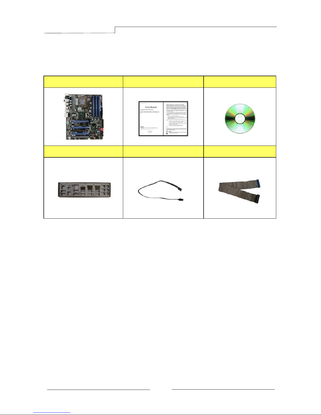
1-2Package Contents
Your Sapphire Pure Black X58 mainboard comes with the following accessories.
1. Mainboard
2. Quick Installation Guide
3. Driver CD
4. I/O Shield
5. SATA Data Cable *6
6. IDE Cable
PB-CI7S41X58 Mainboard
~ 4 ~
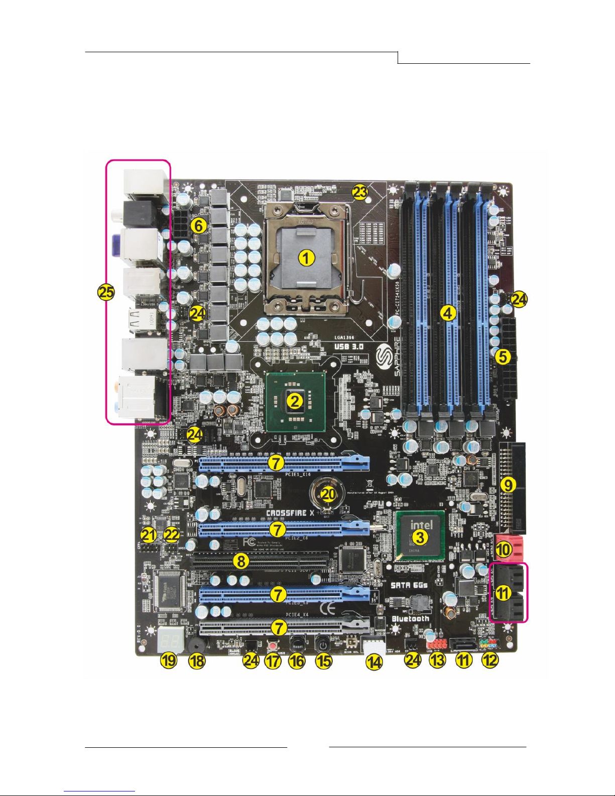
1-3Mainboard Layout
The following figure shows the location of components on the mainboard. See
Page 5 for the Key
PB-CI7S41X58 Mainboard
~ 5 ~
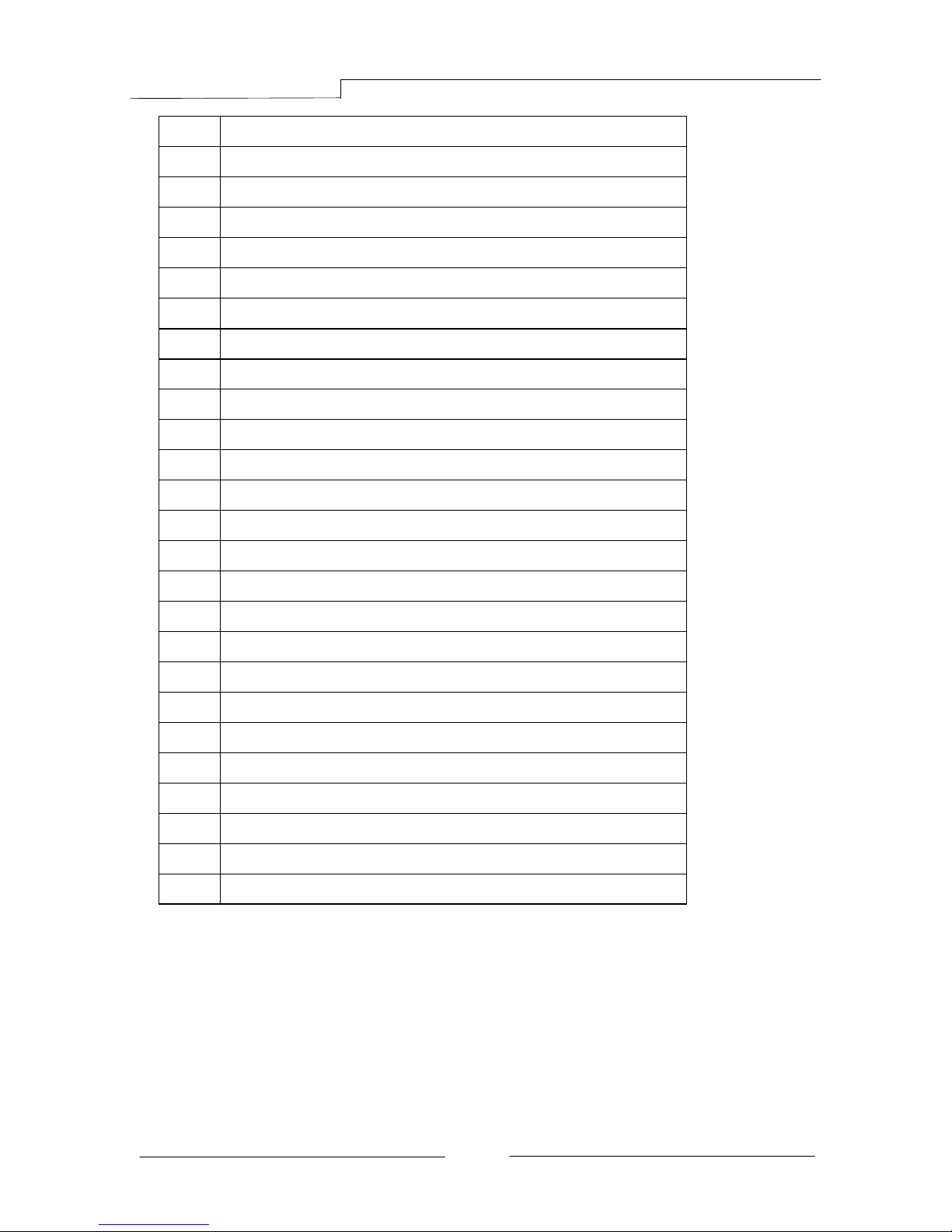
Item
Component description
1
CPU Socket 1366
2
Intel X58 Chipset
3
Intel ICH10R Chipset
4
DDR3 DIMM Slots 1-6
5
24-Pin ATX Power Connector
6
8-pin ATX_12V Power Connector
7
PCI-E x16 Slots1-4
8
PCI Slot
9
IDE Connector
10
SATA3 Connectors *2
11
SATA2 Connectors *5
12
Front Panel Header
13
USB Header
14
IEEE1394a Header
15
Power Button
16
Reset Button
17
Clear CMOS Button
18
PC Speaker
19
Debug LED Display
20
Mainboard Battery
21
Front Panel Audio Header
22
S/PDIF Header
23
CPU Fan Header
24
3-pin Fan Header *5
25
Back Panel Connectors (see next page for detail)
PB-CI7S41X58 Mainboard
~ 6 ~
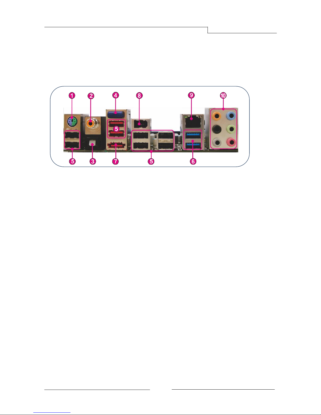
I/O Back Panel
The I/O back panel for this mainboard is shown below. When installing the
mainboard into the computer case, use the bundled I/O shield to protect this
back panel.
1. PS/2 Keyboard/Mouse Port
This connector is used for a keyboard or mouse. You can plug a PS/2
keyboard or mouse directly into this connector.
2. Coaxial S/PDIF-Out
This SPDIF (Sony & Philips Digital Interconnect Format) connector is used
for digital audio transmission to external speakers/amplifier through a
coaxial cable.
3. Optical S/PDIF-Out
This SPDIF (Sony & Philips Digital Interconnect Format) connector is used
for digital audio transmission to external speakers/amplifier through an
optical fiber cable.
4. Bluetooth
Bluetooth wireless technology is an interface intended for wireless
control/data communication
5. USB 2.0 Ports (Eight)
The mainboard provides an OHCI (Open Host Controller Interface) Universal
Serial Bus root for attaching USB devices such as a keyboard, mouse or
other USB-compatible devices. Supports data transfer rates up to 480Mb/s.
6. USB 3.0 ports (two)
USB 3.0 ports are backwardly compatible with USB 2.0 devices. Supports
data transfer rates up to 4.8Gb/s (SuperSpeed).
PB-CI7S41X58 Mainboard
~ 7 ~
7. ESATA Port
The ESATA (External SATA) port provides connection to ESATA hard drives.
8. IEE1394a (Firewire) Port
The IEEE 1394 port provides connection to IEEE 1394 devices.
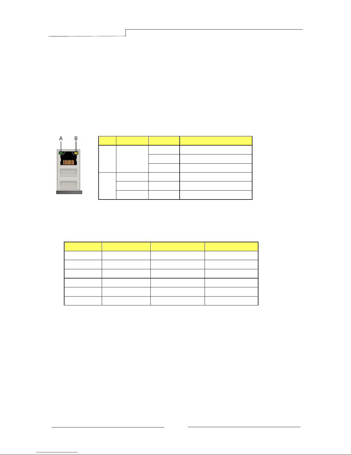
9. LAN Ports with LEDs
The mainboard provides one standard RJ-45 jack for connecting to a Local
Area Network (LAN). Two LEDs are built into the RJ-45 LAN connector.
These LEDs indicate the status of the LAN.
10. Audio Ports
This mainboard provides 2, 6, or 8channel audio. It is easy to differentiate
between the audio functions by referring to the color of the jacks.
Ports
2 channel
6 channel
8 channel
Blue
Line-In
Line-In
Line-In
Lime
Line-Out
Front Stereo-Out
Front Stereo-Out
Pink
Min-In
Min-In
Min-In
Orange
--
Center/Subwoofer
Center/Subwoofer
Black
--
Rear Stereo-Out
Rear Stereo-Out
Gray
--
--
Side Stereo-Out
LED
LED Color
LED state
Indicates
A
Green
Off
LAN link is not established
On
LAN link is established
Blinking
LAN activity is occurring
B
N/A
Off
10 Mb/s data rate
Green
On
100 Mb/s data rate
Yellow
On
1000 Mb/s data rate

PB-CI7S41X58 Mainboard
~ 8 ~
Chapter 2 Installation
2-1 Before You Begin
Please take note of all precautions before you install anything on to the
mainboard or change any of the mainboard settings.
Turn off the power to your system and discharge your body’s static electric
charge by touching a grounded surface—for example, the metal surface of the
power supply—before performing any hardware procedure.
The manufacturer assumes no liability for any damage, caused directly or
indirectly, by improper installation of any components by unauthorized service
personnel. If you do not feel comfortable performing the installation, consult a
qualified computer technician.
Damage to system components, the mainboard , and injury to you may result if
power is applied during installation.
2-2 Installing the I/O Shield
The mainboard comes complete with an I/O shield. When installed in the chassis,
the shield blocks radio frequency transmissions, protects internal components
from dust and foreign objects, and promotes correct airflow within the chassis.
Install the I/O shield before installing the mainboard in the chassis. Place the
shield inside the chassis. Press the shield into place so that it fits tightly and
securely. If the shield does not fit, obtain a properly sized shield from the
chassis supplier.
2-3 Securing to the Chassis
When installing the mainboard, you have to secure the mainboard into the
chassis by fastening with nine screws. Please refer to your chassis manual for
instructions on installing.
PB-CI7S41X58 Mainboard
~ 9 ~
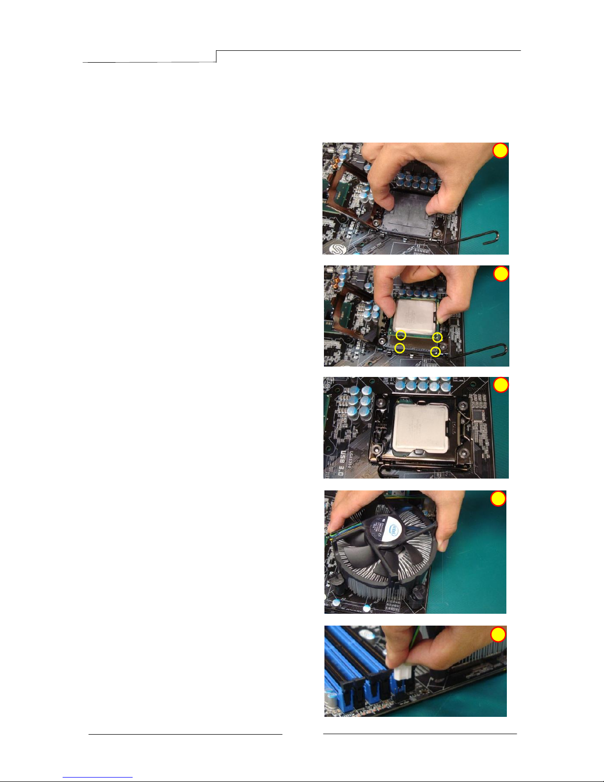
2-4 Installing the CPU and Fan Heatsink
To install the CPU :-
1. Open the socket lever by pushing the
lever down and away from the socket.
Remove the protective socket cover
from the socket. Do not touch the
socket contacts.
Note: Do not discard the protective
socket cover. Be sure to always
replace the cover unless the
CPU is installed.
2. Align the CPU notches to the socket
protrusions. Place CPU straight down
without tilting or sliding it.
3. Close the load plate and engage the
socket lever.
4. To install fan heatsink, align the
holes on the mainboard. Press the
four hooks down to fasten the
cooler. You will hear a “click” upon
full engagement. Gently rotate the
cap clockwise 1/4 turn to fasten the
heatsink onto the mainboard
5. Connect the 4-wire fan cable to the
4-pin CPUFAN header on the
mainboard.
-
1
2
3
4
5
PB-CI7S41X58 Mainboard
~ 10 ~
2-5 Installing System Memory
This mainboard has six 240-pin DIMM sockets for DDR3 memory. These slots
support 1GB, 2GB and 4GB DDR3 DIMMs.
Make sure that you install memory modules of the same type and density in
different channel DIMM slots for Triple-Channel/Dual-Channel mode.
There must be at least one memory bank populated to ensure normal operation
and always inset the memory module into the DIMM slot 1 first.
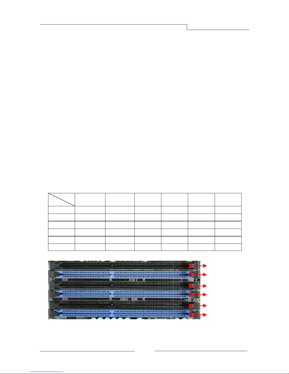
Memory configurations:
Use the following the recommendations for installing memory.
1 DIMM (Single-Channel): install into DIMM slot 1.
2 DIMMs (Dual-Channel): install into DIMM slots 1 and 3.
3 DIMMs (Triple-Channel): install into DIMM slots 1, 3 and 5.
4 DIMMs (Triple-Channel): install into DIMM slots 1, 3, 5and 2.
5 DIMMs (Triple-Channel): install into DIMM slots 1, 3, 5, 2 and 4.
6 DIMMs (Triple-Channel): install into DIMM slots 1, 3, 5, 2, 4 and 6.
DIMM Qty
Location
1 DIMM
(Single Channel)
2 DIMMs
(Dual Channel)
3 DIMMs
(Triple Channel)
4 DIMMs
(Triple Channel)
5 DIMMs
(Triple Channel)
6 DIMMs
(Triple Channel)
DIMM#2
--
--
-- V V
V
DIMM#1
V V V V V
V
DIMM#4
--
--
--
-- V V
DIMM#3
-- V V V V
V
DIMM#6
--
--
--
--
--
V
DIMM#5
--
-- V V V V
DIMM#2
DIMM#1
DIMM#3
DIMM#4
DIMM#6
DIMM#5
PB-CI7S41X58 Mainboard
~ 11 ~
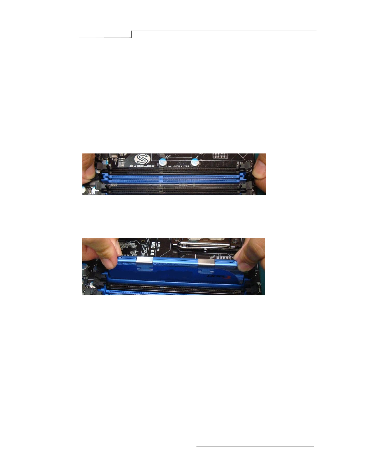
Memory Installation:
DDR3 and DDR2 memory modules are physically different. Please only install
DDR3 DIMMs in this mainboard.
To make sure you have the correct DIMM, check that all the notches line up with
the DDR3 DIMM slot.
To install the DIMM, follow these steps:
1. Pull both clips on either side of the slot outwards. Align the DIMM module
with the slot.
2. Press straight down until the plastic clips close and the module fits tightly
into the DIMM slot.
PB-CI7S41X58 Mainboard
~ 12 ~
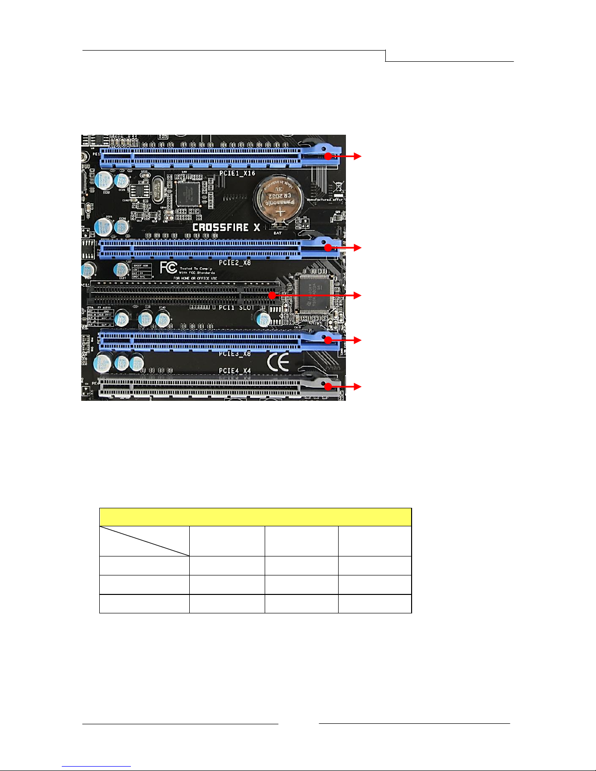
2-6 Installing Expansion Cards
The mainboard provides four PCI Express 2.0 x16 slots and one PCI slot.
PCI-E Slots
The design of this motherboard supports ATI CrossFireXTM multiple graphic card
technology. Please refer to the location of slots and recommended
configuration table for PCI-E operating mode to get the best performance
possible.
Recommended configuration table
Slot location
VGA card
PCIE1_x16
(Blue)
PCIE2_x8
(Blue)
PCIE3_x8
(Blue)
1 VGA card
x16
2 VGA cards
x16
x8
3 VGA cards
x16
x8
x8
To install a PCI Express card:
1. Place the card in an available PCI Express slot and press down on the card
until it is completely seated in the slot. If the card is not seated properly, it
could cause a short across the pins.
2. Secure the card’s metal bracket to the chassis back panel with a screw.
PCIE1_X16
PCI-E2.0 x16 slot (with x16 link, Blue)
PCIE2_X8
PCI-E2.0 x16 slot (with x8 link, Blue)
PCIE3_X8
PCI-E2.0 x16 slot (with x8 link, Blue)
PCI slot (Black)
PCIE4_X4
PCI-E1.0 x16 slot (with x4 link, Gray)
 Loading...