

Page 1
1
Page 2

2
Table of Content
COPYRIGHT STATEMENT ................................................................................................................... 9
WARRANTY......................................................................................................................................... 10
FCC CAUTION .....................................................................................................................................11
SAFE SEATING GESTURES:............................................................................................................. 12
CE STATEMENT OF CONFORMITY .................................................................................................. 12
CHAPTER 1 INTRODUCTION ............................................................................................................ 13
1.1
O
VERVIEW
......................................................................................................................... 13
1.2
F
EATURES
......................................................................................................................... 14
1.3
S
PECIFICATIONS
................................................................................................................ 15
1.3.1
Product Appearance Introduction .................................................................... 16
1.4
S
YSTEM REQUIREMENTS
.................................................................................................... 16
1.5
G
ET YOUR IP AUTOMATICALLY & MANUALLY
....................................................................... 17
1.5.1
Network Testing ................................................................................................. 20
1.5.1.1 Testing with Internet Browser................................................................................ 21
1.5.1.2 Testing wirh DOS (Windows XP platform) ............................................................ 22
CHAPTER 2 HARDWARE INSTALLATION........................................................................................ 24
2.1
D
IAGRAM OF CONNECTING HARDWARE TO
WE-1110 ........................................................... 24
2.1.1
Router Mode Hardware connection and application...................................... 24
2.1.2
AP Mode Hardware connection and application ............................................ 24
2.1.3
Clint Mode Hardware connection and application ......................................... 25
CHAPTER 3 ROUTER MODE............................................................................................................. 26
3.1
A
DMINISTRATOR QUICK SETUP INSTRUCTION
...................................................................... 26
3.2
Q
UICK SETUP
.................................................................................................................... 28
3.2.1
WAN Setup (Internet Connection) .................................................................... 30
3.2.1.1 WAN Type – Static IP .............................................................................................. 31
3.2.1.2 WAN Type – Dynamic IP ......................................................................................... 32
3.2.1.3 WAN Type – PPPoE................................................................................................. 33
3.2.1.4 WAN Type – PPTP................................................................................................... 34
3.2.2
LAN Setup........................................................................................................... 35
3.2.3
Wireless Setup ................................................................................................... 36
3.2.4
Time Server Setup.............................................................................................. 37
3.2.5
Password Setup ................................................................................................. 37
Page 3

3
3.2.6
USB Disk Management Setup ........................................................................... 39
3.2.7
User Account Management Setup.................................................................... 40
3.2.8
Firewall Setup..................................................................................................... 41
3.2.9
QoS Configuration Setup .................................................................................. 42
3.2.10 FTP Server Setup ............................................................................................... 43
3.2.11 Web Camera Server Setup ................................................................................ 44
3.2.12 Printer Server Setup .......................................................................................... 45
3.2.13 Samba Server Configuration Setup ................................................................. 46
3.2.14 Audio Server Setup............................................................................................ 46
3.2.15 Quick Setup Finish............................................................................................. 47
3.3
IP C
ONFIG
......................................................................................................................... 48
3.3.1
WAN..................................................................................................................... 48
3.3.2
LAN...................................................................................................................... 53
3.3.3
Wireless .............................................................................................................. 55
3.3.4
DDNS ................................................................................................................... 60
3.4
A
DVANCE
.......................................................................................................................... 61
3.4.1
NAT ...................................................................................................................... 61
3.4.1.1 Virtual Server .......................................................................................................... 62
3.4.1.2 Virtual DMZ.............................................................................................................. 63
3.4.2
Firewall................................................................................................................ 64
3.4.2.1 Firewall Configuration............................................................................................ 64
3.4.2.2 IP Filter..................................................................................................................... 68
3.4.2.3 MAC Filter................................................................................................................ 70
3.4.2.4 URL Filter................................................................................................................. 71
3.4.3
QoS...................................................................................................................... 73
3.5
S
ERVER
............................................................................................................................. 74
3.5.1
FTP Server .......................................................................................................... 74
3.5.2
Web Camera Server ........................................................................................... 76
3.5.2.1 Web Camera Server Basic Setting ........................................................................ 77
3.5.2.2 Web Camera Advanced Configuration.................................................................. 77
3.5.2.3 Application for Web Camera.................................................................................. 79
3.5.2.3.1 Web Camera Monitoring Application.......................................................................... 79
3.5.2.3.1.1 Web Camera Monitoring via WAN connecting ................................................... 80
3.5.2.3.1.2 Web Camera Motoring via WiFi mobile phone................................................... 82
3.5.2.3.2 Web Camera Recording............................................................................................... 83
3.5.2.3.2.1 Administrator Setting ........................................................................................... 83
3.5.2.3.2.2 Personal Application ............................................................................................ 86
3.5.3
Printer / MFP Server........................................................................................... 87
Page 4

4
3.5.3.1 Printer Setting on PC.............................................................................................. 88
3.5.3.2 How to scan via scanner ........................................................................................ 94
3.5.4
Audio Server....................................................................................................... 96
3.5.5
Samba Server ..................................................................................................... 97
3.5.5.1 How to enter the sharing floder............................................................................. 98
3.6
S
YSTEM MANAGEMENT
..................................................................................................... 100
3.6.1
Reboot............................................................................................................... 100
3.6.2
Change Password ............................................................................................ 101
3.6.3
Firmware Upgrade............................................................................................ 102
3.6.4
Driver Upload.................................................................................................... 103
3.6.5
Profile Save....................................................................................................... 103
3.6.6
Remote Management ....................................................................................... 105
3.6.7
Time................................................................................................................... 106
3.6.8
UPnP setting..................................................................................................... 108
3.6.9
User Account management............................................................................. 109
3.6.10 Folder Management ......................................................................................... 110
3.6.11 Email Alert..........................................................................................................111
3.7
L
OG & STATUS
.................................................................................................................113
3.7.1
Network Configuration .................................................................................... 113
3.7.2
User Account List ............................................................................................ 115
3.7.3
Event Log.......................................................................................................... 115
3.8
L
OGOUT
...........................................................................................................................116
3.9
P
ERSONAL CONFIGURATION
..............................................................................................117
3.9.1
Anonymous ...................................................................................................... 119
3.9.2
My Document.................................................................................................... 120
3.9.3
My Webcam ...................................................................................................... 121
3.9.4
My Status .......................................................................................................... 122
3.10 S
ITE MAP
........................................................................................................................ 123
CHAPTER 4 AP MODE ..................................................................................................................... 124
4.1
A
DMINISTRATOR QUICK SETUP INSTRUCTION
.................................................................... 124
4.2
Q
UICK SETUP
.................................................................................................................. 126
4.2.1
LAN Setup......................................................................................................... 128
4.2.2
Wireless Setup ................................................................................................. 129
4.2.3
Time Server Setup............................................................................................ 130
4.2.4
Password Setup ............................................................................................... 130
4.2.5
USB Disk Management Setup ......................................................................... 131
4.2.6
User Account Management Setup.................................................................. 133
Page 5

5
4.2.7
FTP Server Setup ............................................................................................. 134
4.2.8
Web Camera Server Setup .............................................................................. 134
4.2.9
Printer Server Setup ........................................................................................ 135
4.2.10 Samba Server Configuration Setup ............................................................... 136
4.2.11 Audio Server Setup.......................................................................................... 136
4.2.12 Quick Setup Finish........................................................................................... 137
4.3
IP C
ONFIG
....................................................................................................................... 138
4.3.1
LAN.................................................................................................................... 138
4.3.2
Wireless ............................................................................................................ 140
4.4
S
ERVER
........................................................................................................................... 144
4.4.1
FTP Server ........................................................................................................ 144
4.4.2
Web Camera Server ......................................................................................... 146
4.4.2.1 Web Camera Server Basic Setting ...................................................................... 146
4.4.2.2 Web Camera Advanced Configuration................................................................ 147
4.4.2.3 Application for Web Camera................................................................................ 148
4.4.2.3.1 Web Camera Monitoring Application........................................................................ 148
4.4.2.3.2 Web Camera Recording............................................................................................. 153
4.4.2.3.2.1 Administrator Setting ......................................................................................... 153
4.4.2.3.2.2 Personal Application .......................................................................................... 155
4.4.3
Printer/MFP Server........................................................................................... 156
4.4.3.1 Printer Setting on PC............................................................................................ 157
4.4.3.2 How to scan via scanner ...................................................................................... 163
4.4.4
Audio Server..................................................................................................... 165
4.4.5
Samba Server ................................................................................................... 166
4.4.5.1 How to enter the sharing floder........................................................................... 167
4.5
S
YSTEM MANAGEMENT
.................................................................................................... 168
4.5.1
Reboot............................................................................................................... 168
4.5.2
Change Password ............................................................................................ 169
4.5.3
Firmware Upgrade............................................................................................ 170
4.5.4
Driver Upload.................................................................................................... 171
4.5.5
Profile Save....................................................................................................... 172
4.5.6
Remote Management ....................................................................................... 174
4.5.7
Time................................................................................................................... 175
4.5.8
UPnP Setting .................................................................................................... 176
4.5.9
User Account Management............................................................................. 177
4.5.10 Folder Management ......................................................................................... 179
4.5.11 Email Alert......................................................................................................... 180
4.6
L
OG & STATUS
................................................................................................................ 182
Page 6

6
Network Configuration...................................................................................................... 182
User Account List.............................................................................................................. 183
Event Log 184
4.7
L
OGOUT
.......................................................................................................................... 185
4.8
P
ERSONAL CONFIGURATION
............................................................................................. 185
4.8.1
Anonymous ...................................................................................................... 187
4.8.2
My Document.................................................................................................... 188
4.8.3
My Webcam ...................................................................................................... 189
4.8.4
My Status .......................................................................................................... 190
4.9
S
ITE MAP
........................................................................................................................ 191
CHAPTER 5 CLIENT MODE ............................................................................................................. 192
A
DMINISTRATOR QUICK SETUP INSTRUCTION
................................................................................. 192
Q
UICK SETUP
............................................................................................................................... 194
5.2.1
Site Survey........................................................................................................ 196
5.2.2
Wireless Setup ................................................................................................. 196
5.2.3
Time Server Setup............................................................................................ 197
5.2.4
Password Setup ............................................................................................... 198
5.2.5
USB Disk Management Setup ......................................................................... 200
5.2.6
User Account Management Setup.................................................................. 201
5.2.7
FTP Server Setup ............................................................................................. 202
5.2.8
Web Camera Server Setup .............................................................................. 203
5.2.9
Printer Server Setup ........................................................................................ 204
5.2.10 Samba Server Configuration Setup ............................................................... 205
5.2.11 Audio Server Setup.......................................................................................... 205
5.2.12 Quick Setup Finish........................................................................................... 206
IP C
ONFIG
.................................................................................................................................... 206
LAN 206
Site Survey ......................................................................................................................... 208
S
ERVER
211
FTP Server 211
Web Camera Server........................................................................................................... 213
5.4.2.1 Web Camera Server Basic Setting ...................................................................... 213
5.4.2.2 Web Camera Server Advanced Configuration.................................................... 214
5.4.2.3 Application for Web Camera................................................................................ 215
5.4.2.3.1 Web Camera Monitoring Application........................................................................ 215
5.4.2.3.2 Web Camera Recording............................................................................................. 219
5.4.2.3.2.1 Administrator Setting ......................................................................................... 219
Page 7

7
5.4.2.3.2.2 Personal Application .......................................................................................... 221
Printer / MFP Server ..........................................................................................................222
5.4.3.1 Printer Setting on PC............................................................................................ 223
5.4.3.2 How to scan via scanner ...................................................................................... 229
5.4.4
Audio Server..................................................................................................... 231
5.4.5
Samba Server ................................................................................................... 232
5.4.5.1 How to enter the sharing floder........................................................................... 233
5.5
S
YSTEM MANAGEMENT
.................................................................................................... 235
5.5.1
Reboot............................................................................................................... 235
5.5.2
Change Password ............................................................................................ 236
5.5.3
Firmware Upgrade............................................................................................ 237
5.5.4
Driver Upload.................................................................................................... 238
5.5.5
Profile Save....................................................................................................... 239
5.5.6
Remote Management ....................................................................................... 240
5.5.7
Time................................................................................................................... 241
5.5.9
User Account Management............................................................................. 243
5.5.10 Folder Management ......................................................................................... 244
5.5.11 Email Alert......................................................................................................... 245
5.6
L
OG & STATUS
................................................................................................................ 248
5.6.1
Network Configuration .................................................................................... 248
5.6.2
User Account List ............................................................................................ 249
5.6.3
Event Log.......................................................................................................... 249
5.7
L
OGOUT
.......................................................................................................................... 250
5.8
P
ERSONAL CONFIGURATION
............................................................................................. 250
5.8.1
Anonymous ...................................................................................................... 252
5.8.2
My Document.................................................................................................... 253
5.8.3
My Webcam ...................................................................................................... 254
5.8.4
My Status .......................................................................................................... 255
5.9
S
ITE MAP
........................................................................................................................ 256
CHAPTER 6 DDNS SERVICE ACCOUNT........................................................................................ 257
CHAPTER 7 Q & A ............................................................................................................................ 263
I
NSTALLATION
............................................................................................................................... 263
LED 263
IP A
DDRESS
................................................................................................................................. 264
OS S
ETTING
................................................................................................................................. 265
WE-1110 S
ETUP
.......................................................................................................................... 267
W
IRELESS
LAN ............................................................................................................................ 268
Page 8

8
USB FTP S
ERVER
........................................................................................................................ 272
W
EBCAM SERVER
......................................................................................................................... 272
P
RINTER SERVER
.......................................................................................................................... 273
S
UPPORT
...................................................................................................................................... 273
O
THERS
274
USB D
EVICE
................................................................................................................................ 274
CHAPTER 8 APPENDIX.................................................................................................................... 275
MFP 275
W
EB CAMERA
............................................................................................................................... 276
USB S
TORAGE DEVICE
................................................................................................................. 284
OS 285
W
EB BROWSER
............................................................................................................................ 285
SADOGO U
TILITY
........................................................................................................................ 285
Page 9

9
Copyright Statement
This user’s manual, includes the products and software may be reproduced, transcribed,
transmitted and stored. That totally depends on the legal authorized copyright. Furthermore,
it can be translated into any language in any form or by any means, except some documents
or public software without the copy permission of our company.
ACCORDING TO THE AMERICA COPYRIGHT RULES IN 1976, PEOPLE CANNOT
PUBLISH ANY UNAUTHORIZED CREATION IN ANY FORM OR BY ANY MEANS. IN
DETAIL, WHOLE CREATION, EVEN PART OF CREATION CANNOT BE PUBLISHTED VIA
THE MENTIONED METHODS BY OTHERS. FOR INSTANCE, DOCUMENTATION OF
TRANSLATION OR MODIFICATION IS PROHIBITED.
All trademarks and trade names are the properties of their respective owners.
COPYRIGHT © 2007 ALL RIGHTS RESERVED BY SAPIDO.
Page 10

10
Warranty
One-Year Warranty is provided for consumer products. This warranty is subject to the
conditions and limitations set forth herein.
("We") warrants and tests the Product to be free from defects in material and workmanship
and to conform to published specifications. During the warranty period, should the Product
fail under normal use in the recommended environment due to improper workmanship or
materials, we will repair the Product or replace it with a comparable one.
This warranty is for a specific period of time from the date of purchase. Proof of date of
purchase is required. We will inspect the Product and make the decision regarding repair or
replacement. We reserve the right to provide a functionally equivalent refurbished
replacement Product.
This warranty does not apply to Product failure due to accident, abuse, mishandling, improper
installation, alteration, improper usage, or problems with electrical power. The Product must
be used with devices that conform to the recommended industry standards. We will not be
liable for damages resulting from a third party device that causes the Product to fail. We shall
in no event be liable for any consequential, indirect, or incidental damages, lost profits, lost
business investments lost goodwill, or interference with business relationships as a result of
lost data. We are also not responsible for damage or failure of any third party equipment,
even if we have been advised of the possibility. This limitation does not apply to the extent
that it is illegal or unenforceable under applicable law.
The limited warranty is exclusive, with no other warranties, implied or statutory, including, but
not limited to any implied warranty of merchantability or fitness for a particular purpose. The
technical supports or advices we provided do not affect this warranty in any part.
Page 11

11
FCC Caution
1. The device complies with Part 15 of the FCC rules. Operation is subject to the following
two conditions:
(1) This device may not cause harmful interference, and this device must accept any
interference received, including interference that may cause undesired operation.
2. FCC RF Radiation Exposure Statement: The equipment complies with FCC RF radiation
exposure limits set forth for an uncontrolled environment. This equipment should be
installed and operated with a minimum distance of 20 centimeters between the radiator
and your body.
3. This Transmitter must not be co-located or operating in conjunction with any other antenna
or transmitter.
4. Changes or modifications to this unit not expressly approved by the party responsible for
compliance could void the user authority to operate the equipment.
Page 12
12
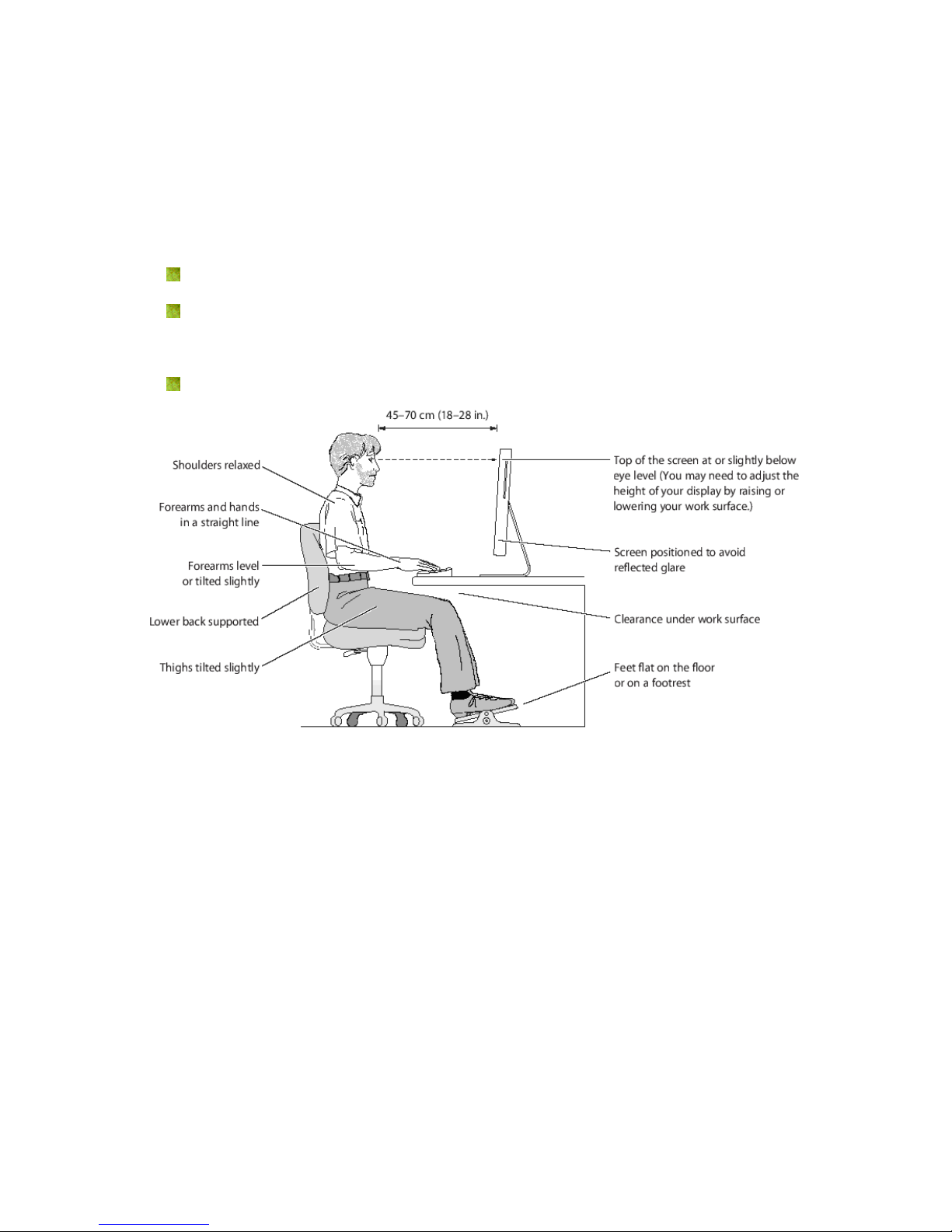
Safe Seating Gestures:
You should follow the manufacturer’s instructions for adjusting the backrest to fit your body
properly.
An adjustable chair that provides firm, comfortable support is best.
Adjust the height of the chair so your thighs are horizontal and your feet flat on the
floor.
The back of the chair should support your lower back (lumbar region).
CE Statement of Conformity
Our product has been tested in typical configuration by Ecam Sertech Corp and was found to
comply with the essential requirement of “Council Directive on the Approximation of the Laws
of the Member States relating to Electromagnetic Compatibility” (89/336/EEC; 92/31/EEC;
93/68/EEC)
Page 13

13
Chapter 1 Introduction
1.1 Overview
WE-1110 (NES-Mini Server Router with MFP) in order to combine functions, such as Router,
Bridge, AP and USB port application...etc., the main distinguishing feature can link the USB
MFP, providing to scanner, printer and card reader share to the user in LAN, or match with an
USB web camera to be used as instant supervision tool, can also mount USB hard drive or
portable disc, then become a FTP server.
When WE-1110 link to USB audio adapter, you can play in the distant place through the
network the audio file that the PC carry. Regard as the use of broadcast.
The WE-1110 physical volume of palm dimension and weight can not compare with 500
grams' being agile doesn't have space, easy to take convenient wireless to also get to the
Internet, concert built-in the transformer post core design, mounting the household-use
socket can immediately use, fit often go out of the business travel a personage to use.
Page 14

14
1.2 Features
WE-1110’s main functions, including Wireless Access, Webcam Server, MFP Server, FTP
Server, Samba Server, Audio Server and IP Sharing are shown as below. These features are
belonging to WE-1110 and applying instructions of the User’s Manual will not only fulfill your
requirements, but also ease your inconvenience from the job.
FTP Server
WE-1110 supports FAT32/EXT3 file system format. Plug with USB hard drive or thumb drive,
it will become a FTP server, and the users can share files on the Internet.
Samba Server
WE-1110 supports Samba Server function. Samba Server via “My Network Places” supports
sharing data and printer for user of LAN.
Audio Server
Make use of a speaker with the adapter connectivity attached, can broadcast music directly
through the LAN.
MFP Server
WE-1110 supports USB MFP Printer sharing. It allows all computers sharing the cardreader,
scanner and printer on your network. With LPR protocol, users can use printer from both
WAN and LAN.
Webcam Server
The product support USB Web Camera, which provides easy and affordable solution for
home security. It allows users monitoring home from anywhere via online webcam.
High Speed Wireless LAN
WE-1110 support IEEE 802.11g wireless LAN. It can transmit data up to 54Mbps. It keeps
compatibility with existing IEEE 802.11b device and complies with IEEE 802.11b standard.
The integrated Wireless Access Point with 64-bit and 128-bit WEP encryption functionality
allows the wireless router to link a broadband internet connection to your local network of
wireless client securely. It also support WPA, 802.1x for wireless security.
Page 15

15
1.3 Specifications
Router Mode
Connector: 1x RJ-45,10/100 Base TX for WAN
1x RJ-45,10/100 Base TX for LAN
AP Mode Connector: 2x RJ-45,10/100 Base TX for LAN
Three Mode
Client Mode
Connector: 2 RJ-45, 10/100 Base TX to LAN Wireless to
Access Point.
WLAN
Connector: Wireless
Support : IEEE 802.11b/g
USB2.0 Port
Connector : 2 x Standard _A type
Support : USB Webcam、USB MFP、USB Flash/HDD
Interface
Slide Switch Router / AP / Client mode exchange function.
Web-Base Windows IE / Linux Firefox / MAC Safari
WAN Protocol PPPoE / PPTP / Static IP/ Dynamic IP
WLAN WDS / WEP Key / WPA / WPA-PSK / MAC Access Control /Hidden SSID
Routing UPnP / DHCP / DNS / WINS / DDNS
NAT Virtual Server / Virtual DMZ
Firewall MAC Filter / URL Filter / SPI / DoS Protection / IP Packet Filter
QoS 3-level priority for each application port
Folder
Management
Disk Format
Function
User Account
Management
User account create and access control
Webcam Server
Webcam view via browser by internet real time
Picture monitor from LAN/WAN PC
Picture recording to FTP server or USB HDD
MFP Server
Printer via WAN/LAN PC
Including scanner and card reader
Printer Sharing
Samba Server File Sharing
Audio Server Listen to the music via LAN
Application
FTP Server
Anonymous login
User login
Administrator
Quick Setup Wizard / Site Map
Setup wizard / General Setup
Management
Personal Panel Anonymous / My Document / My Webcam / My Status
Dimension 91mm (L) x 80mm (W) x 29mm (H)
Others
Power AC 100 V ~ 240 V
Notice: Firmware Upgrade Available through download.
Page 16
16
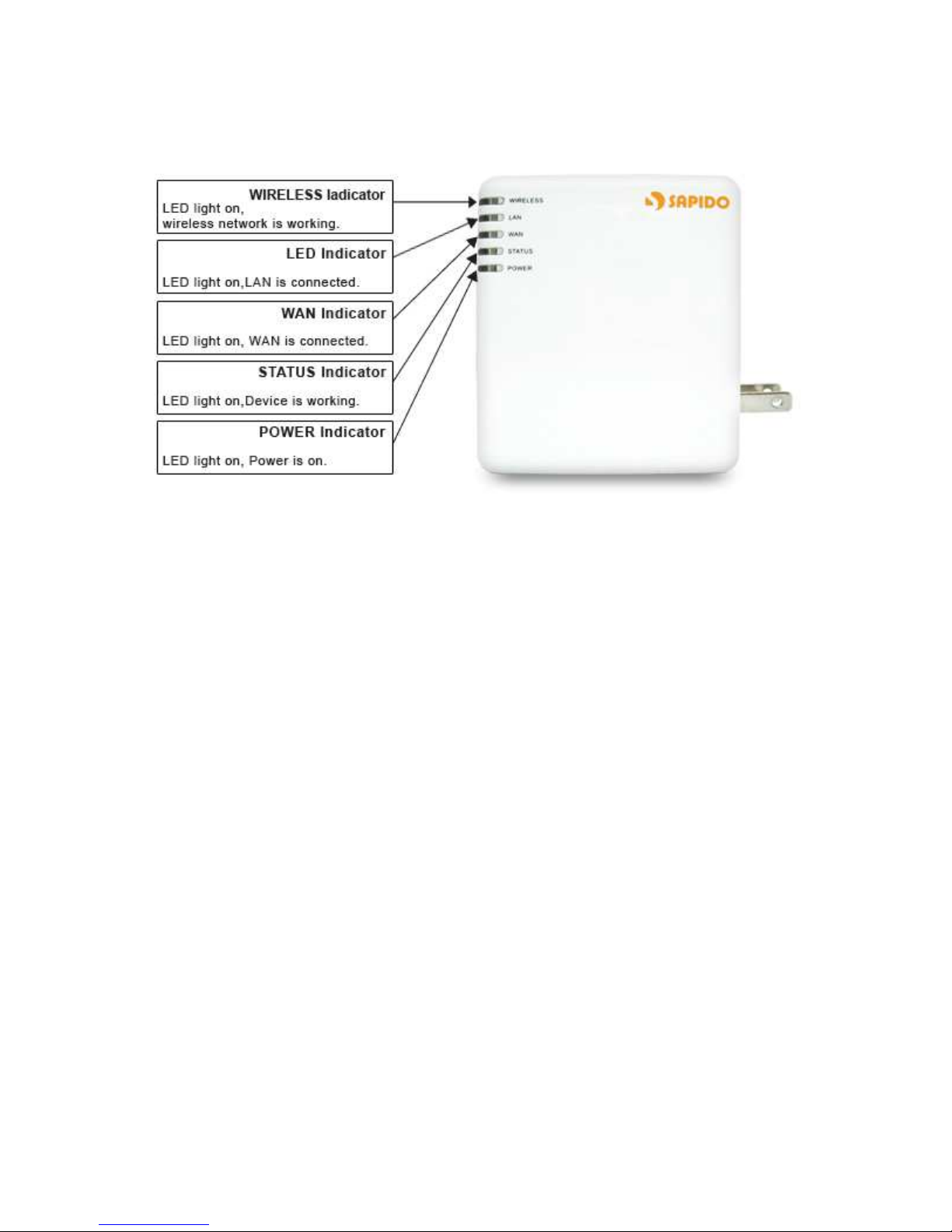
1.3.1 Product Appearance Introduction
1.4 System Requirements
To begin with WE-1110, you must have the following minimum system requirements. If your
system can’t correspond to the following requirements, you might get something unknown
troubles on your system.
XDSL/Cable Modem and broadband Internet Account.
One Ethernet (10 BASE-T or 10/100 BASE-TX) network interface card.
TCP/IP and at least one web browser software installed (E.g.: Internet Explorer or
Netscape).
At lease one 802.11g (54Mbps) or one 802.11b (11Mbps) wireless adapter for wireless
mobile clients.
Recommended OS: Win2000 or WinXP / Linux.
Page 17
17
1.5 Get your IP Automatically & Manually
After WE-1110 connected with your computer, please make sure your IP is in the automatic
IP position or you adjust it as manually in order to activate the network from home to Internet.
If you don’t know how to enter the settings, please follow the steps as below.
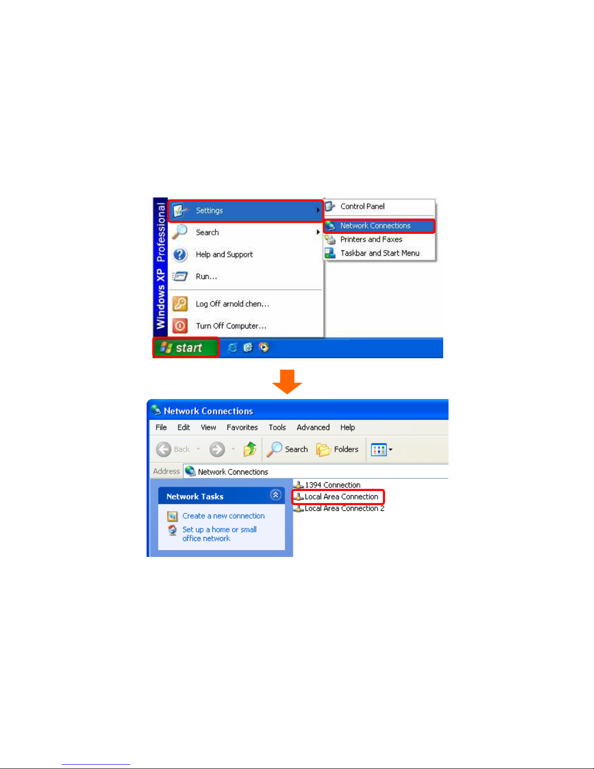
【Step1】
Go to Start > Settings > Network Connections and then select Local Area Connection.
Page 18
18
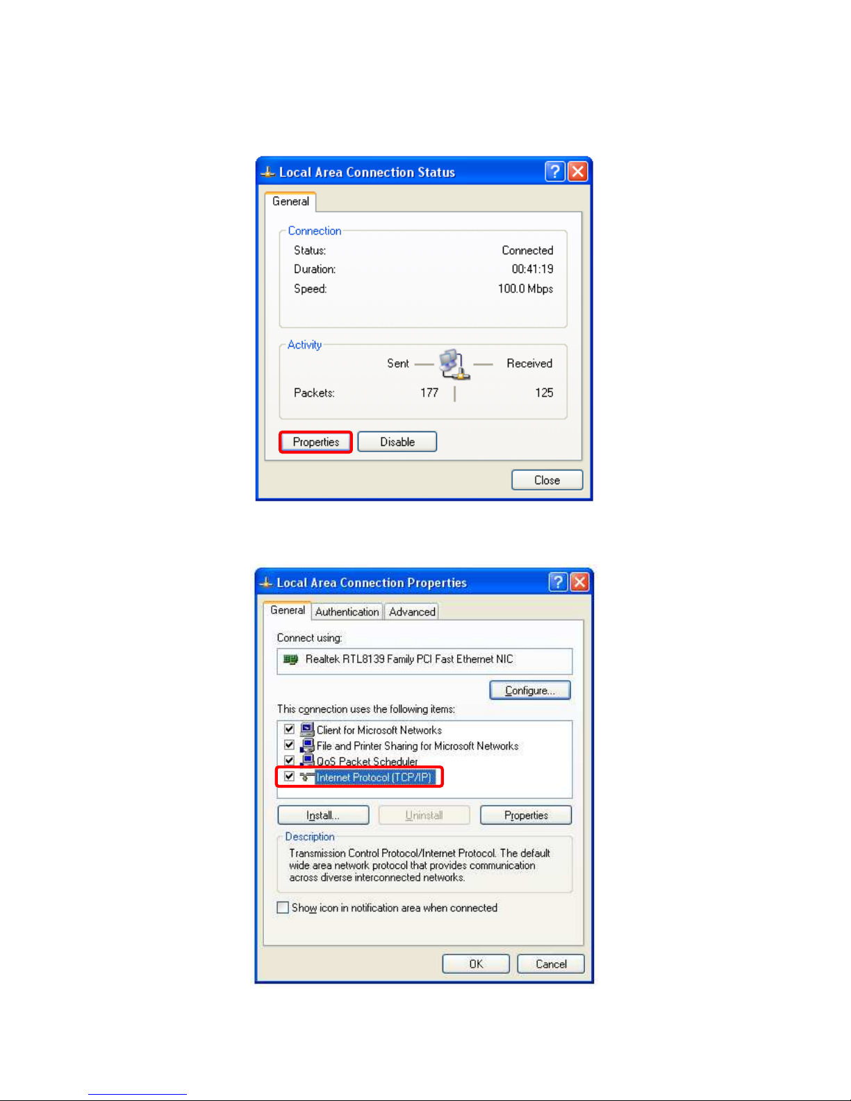
【Step2】
Click on Properties button.
【Step3】
Double click on Internet Protocol (TCP/IP).
Page 19
19
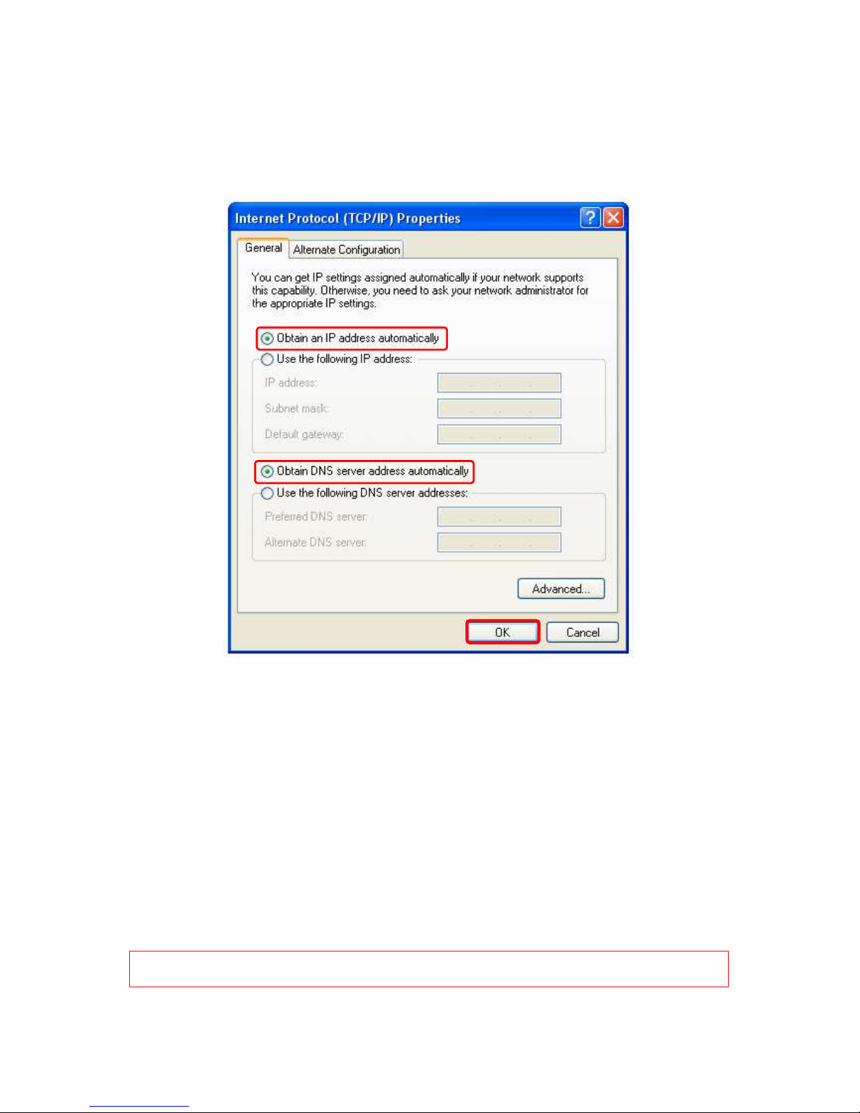
【Step4-1】
For getting IP automatically if you are one of the users under WE-1110, please skip “Use
the following IP address” and then select “Obtain an IP address automatically” and
“Obtain DNS server address automatically” and then click on “OK” button.
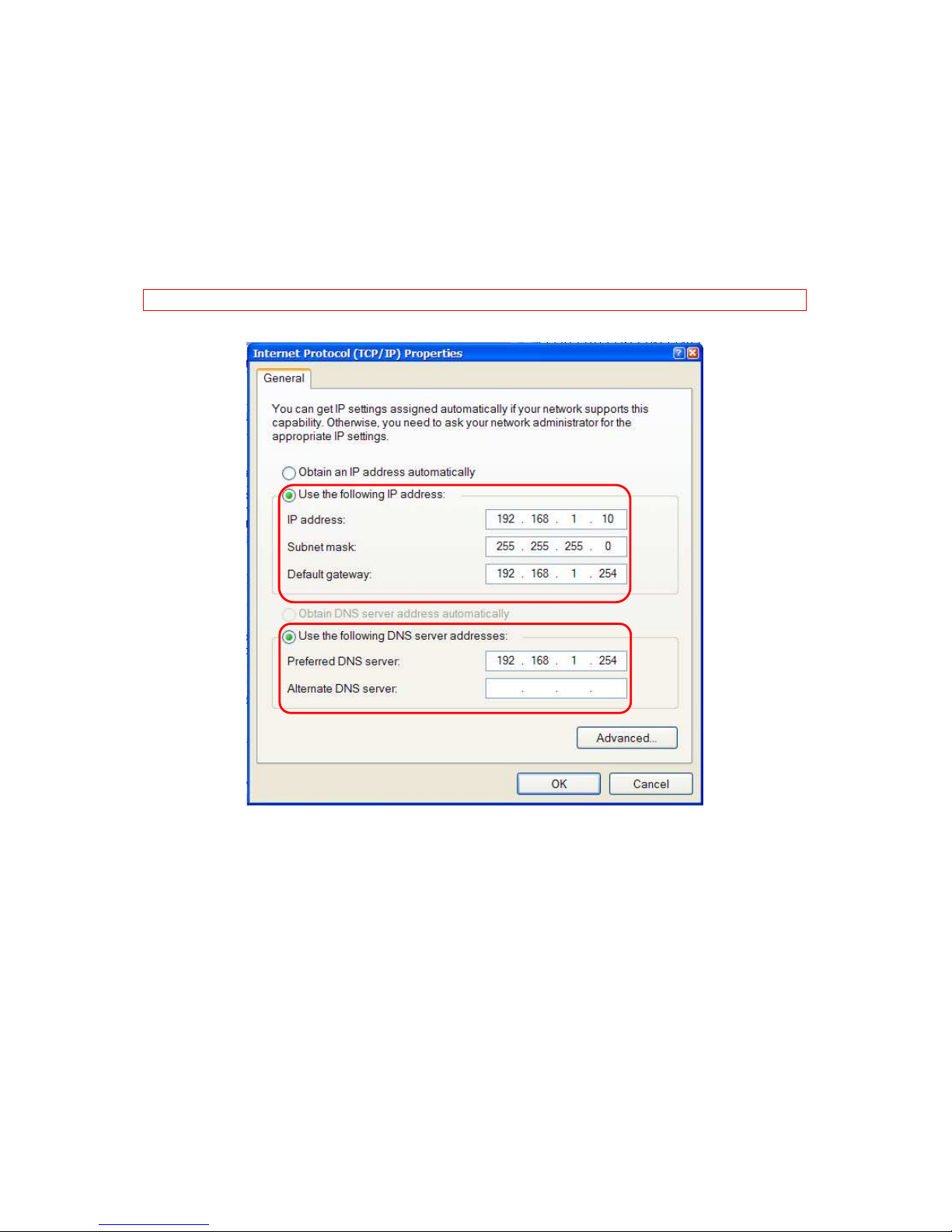
【Step4-2】
For getting IP manually in order to specify a Virtual Server, such as Printer Server, FTP
Server or SNMP Server and so on, please skip “Obtain an IP address automatically” and
then select “Use the following IP address”. And the following default setting of WE-1110
should be noted:
IP Address: 192.168.1.10 (as your Printer Server for example)
Subnet Mask: 255.255.255.0
Default gateway: 192.168.1.254 (for AP Mode, the default gateway for Router Mode is
192.168.1.1)
Notice: If you configure your computer’s IP Address manually, it needs to be on the
same network segment.
Page 20
20
For example:
IP Address: 192.168.1.xxx (xxx can be any number between 2 and 253, but it can’t repeat,
we use 10 to be the example.)
Subnet Mask: 255.255.255.0
Gateway: 192.168.1.254 (this is the IP address of the WE-1110 in AP Mode)
DNS: 192.168.1.254 (use the WE-1110’s IP address or on your own choice).
Notice: IP address and Default gateway couldn’t be the same.
1.5.1 Network Testing
There are two ways to test your Network whether it can work on Internet or not. They are
“Testing with Internet Browser” and “Testing with Dos”.
Page 21
21
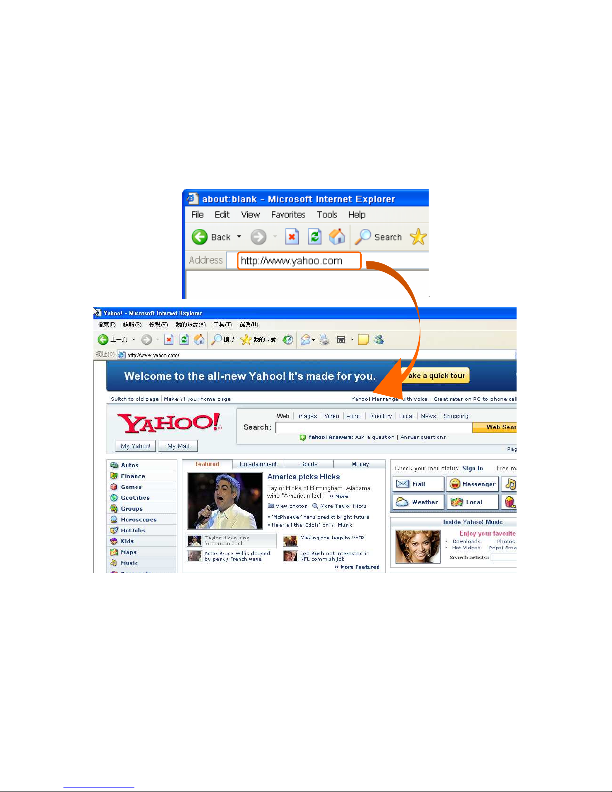
1.5.1.1 Testing with Internet Browser
Open an Internet Browser, such as Internet Explore or Netscape. Input a valid web address
you like http://www.yahoo.com for example in the web address blank and then press Enter.
If it can work, the website will appear, that means your Network to the Internet is under
normal situation.
Page 22
22
1.5.1.2 Testing wirh DOS (Windows XP platform)
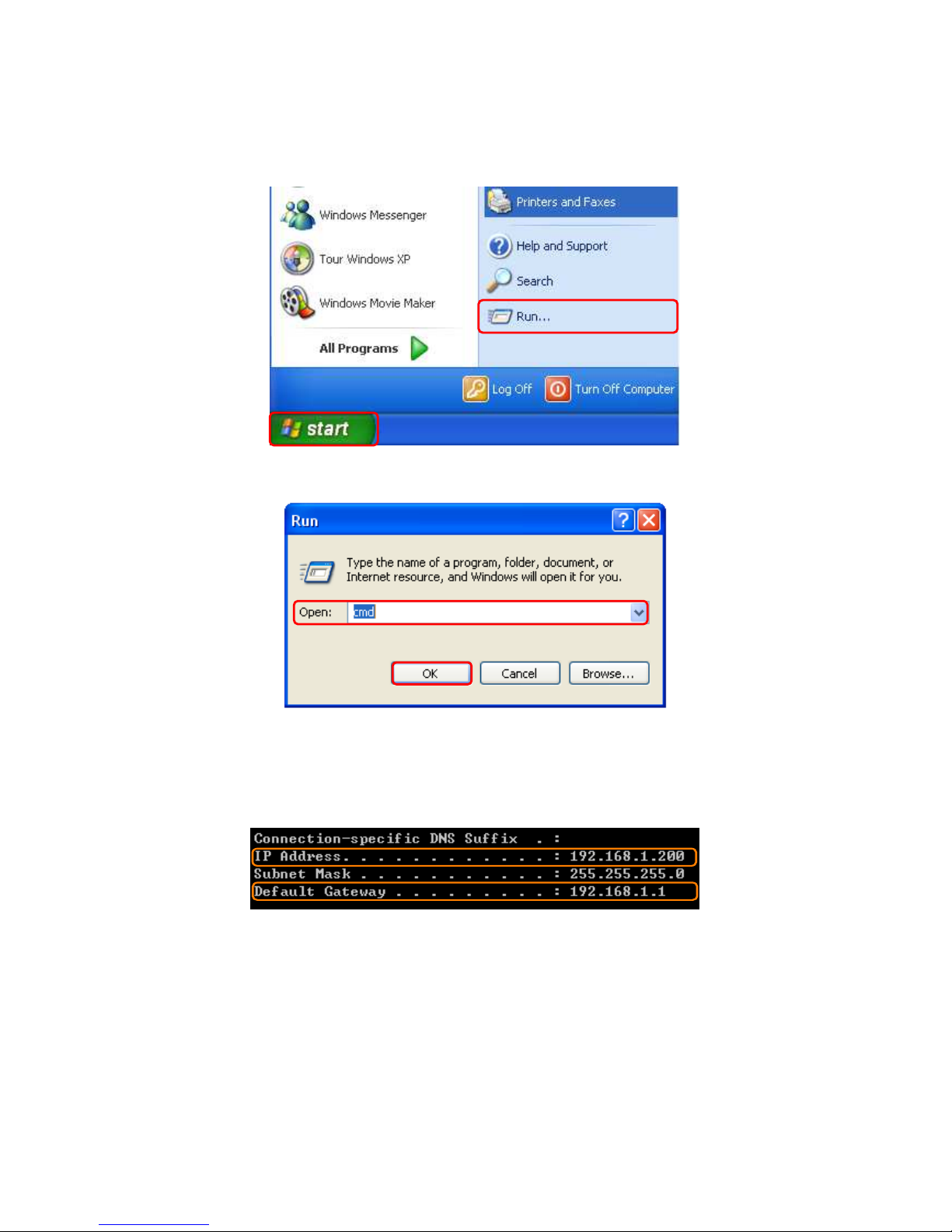
【【【【Step1】】】】
Go to start > Run.
【【【【Step2】】】】
Input cmd in the blank, and then click on OK button. The DOS will appear.
【【【【Step3】】】】
Input ipconfig in the flashing area then press Enter. You will get an IP Address
192.168.1.200 for example, Default Gateway as 192.168.1.1.
【【【【Step4】】】】
Ping a legal WAN Address such as 192.168.1.254 If it can work, it will show Reply from
192.168.1.254: bytes = 32 time = 3ms TTL =64 for example.
Page 23
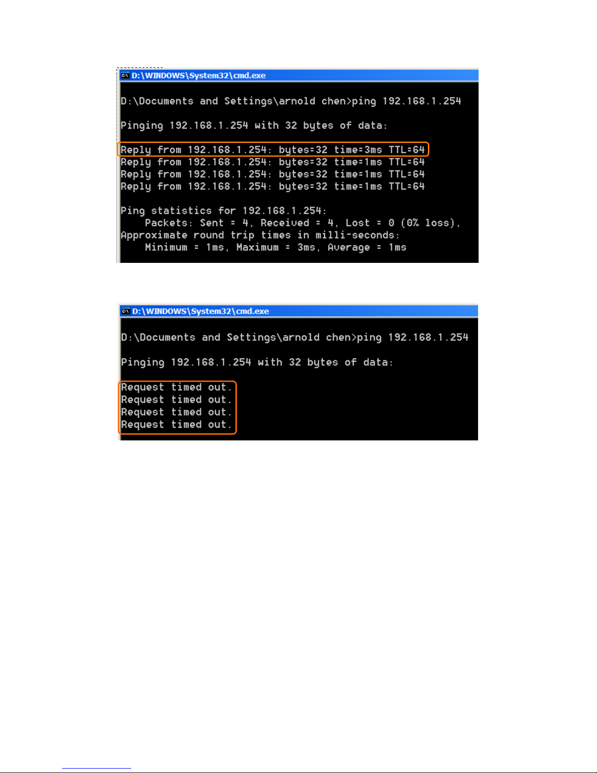
23
If it can’t work, it will show Request timed out.
Page 24

24
Chapter 2 Hardware Installation
2.1 Diagram of connecting hardware to WE-1110
The WE-1110 is a portable and convenient wireless solution for the traveling business person
delivering 802.11g wireless connectivity with a maximum wireless signal rate of up to 54Mbps.
Use it in conference rooms, hotel rooms, or even at hotspots. The Wireless Pocket
Router/AP might be small in size, but huge in functionality, supporting multiple operation
modes, including Access Point (AP) mode, Router mode, and Wireless Client mode. You can
switch among these modes easily by using the WE-1110's 3-way configuration slide switch.
Moreover, there are 2 USB ports support with WE-1110; user can plug the USB devices
including Flash Disk, Web Camera and MFP (including printer, scanner, and cardreader).
Warning: Before remove the slide switch, please power-off the router firstly. Moreover,
please stay over 5 seconds between power-off / power-on condition.
2.1.1 Router Mode Hardware connection and application
When NES Mini Server Router with MFP switches to Router Mode, there will be each WAN
and LAN port existing, the administrator can do the Quick Setup including WAN Setup, LAN
Setup, Wireless Setup, USB Disk Management Setup, User Account Management Setup,
Firewall Setup, QoS Setup, FTP Server Setup, Web Camera Setup, Samba Server Setup,
Audio Server Setup, MFP Server Setup, System Time Setup and Password Setup.
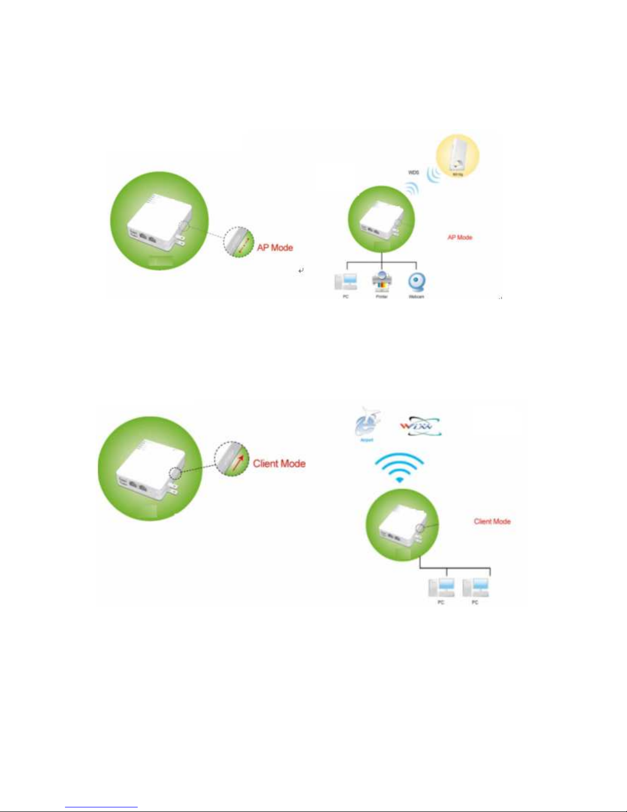
2.1.2 AP Mode Hardware connection and application
Under AP Mode, it supports 2 LAN ports as Bridge, and user can connect to NES Mini Server
Router with MFP via LAN port or Wireless (WDS). The administrator can do the Quick Setup
Page 25
25
including LAN Setup, Wireless Setup, USB Disk Management Setup, User Account
Management Setup, FTP Server Setup, Audio Server Setup, Web Camera Setup, Time
Server Setup, Password Setup, Samba Server Setup and MFP Server Setup.
2.1.3 Clint Mode Hardware connection and application
As Client Mode, NES Mini Server Router with MFP will be a Wireless Adapter, and users can
plug cable to each 2 LAN ports and then connect Internet via Wireless.
Page 26
26
Chapter 3 Router Mode
3.1 Administrator Quick Setup Instruction
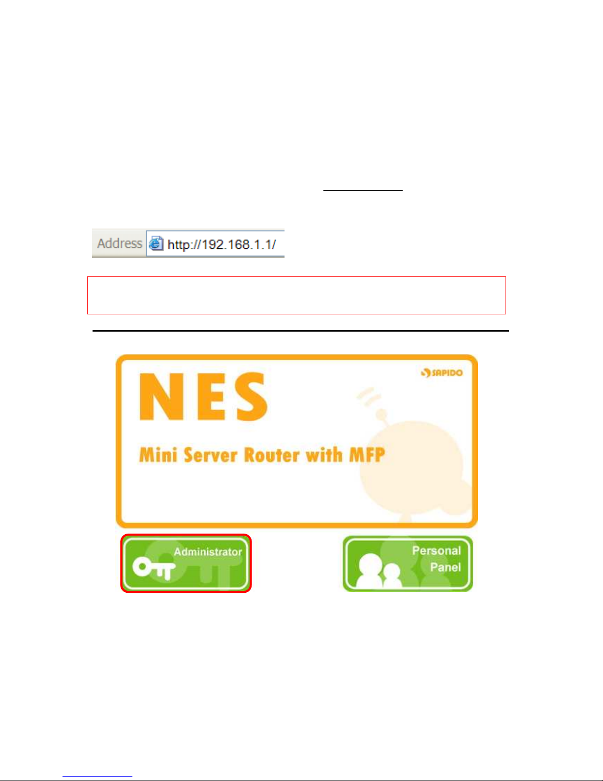
Make sure to switch the mode into Router Mode, then open a Microsoft Internet Explorer,
Mozilla Firefox or Apple Safari browser, and input http://192.168.1.1
(Default Gateway) into
browser’s blank.
Notice: If the homepage doesn’t appear, please check if the TCP/IP configuration is
obtaining IP address automatically or not. If you don’t know how to do, please
refer to “1.5 Get your IP Automatically & Manually”.
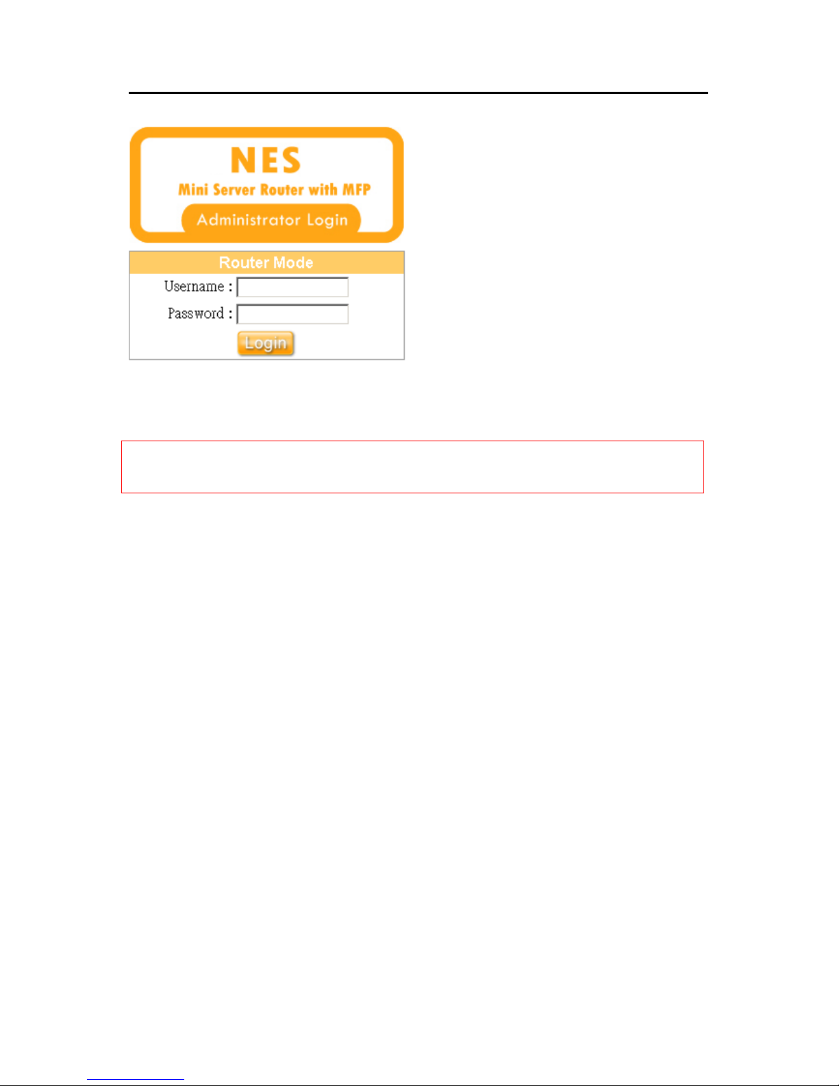
Home Page
Please click on Administrator button to login to setup at first time, also can change any
settings in future. Only the Administrator has the right to set and change all settings.
Page 27
27
User Name and Password
The default values for Username and Password are “admin” and “admin” (all in lowercase
letters).
Notice: Only the password can be changed, please read setup “3.2.5 Password Setup” or
“3.6.2 Change Password”. In order to protect your own settings, it’s strongly
recommended to change the password before you finish the Router Basic Setup.
Page 28
28
3.2 Quick Setup
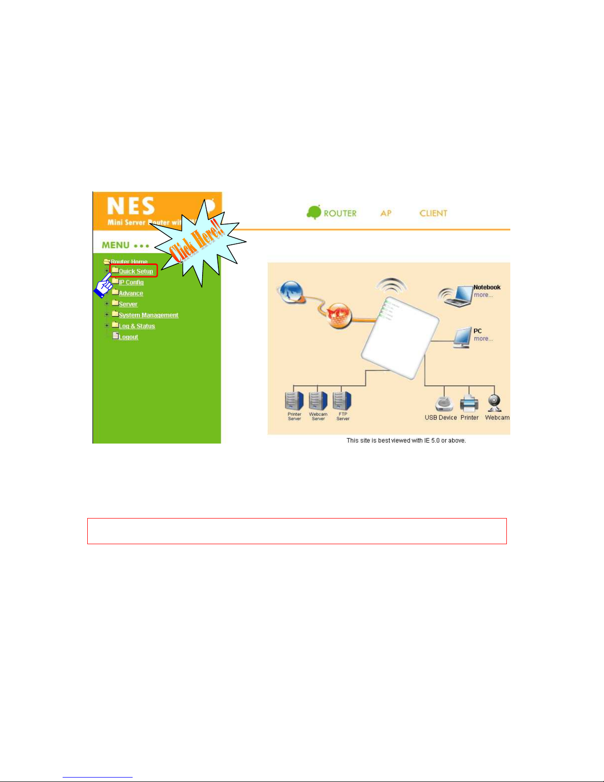
Typical Configuration Manager Page consists of two separate frames. The left frame
contains all the means available for device configuration. Menus are indicated by file icons,
and related menus are grouped into categories, such as LAN, WAN and etc., and indicated
by folder icon, depending on whether the group of menus are expanded or not. You can
click on any of these to display a specific configuration page.
The above diagram shows all PCs and devices connected to your WE-1110 and their status.
Click on Quick Setup in the left screen of the main menu. Then you’ll see the “Basic” and
“Application” selecting screen appears and do the setting for each items.
Note: The device model name of USB Device, Webcam and Printer will be shown under
the picture of each device if the Product supports.
Page 29
29
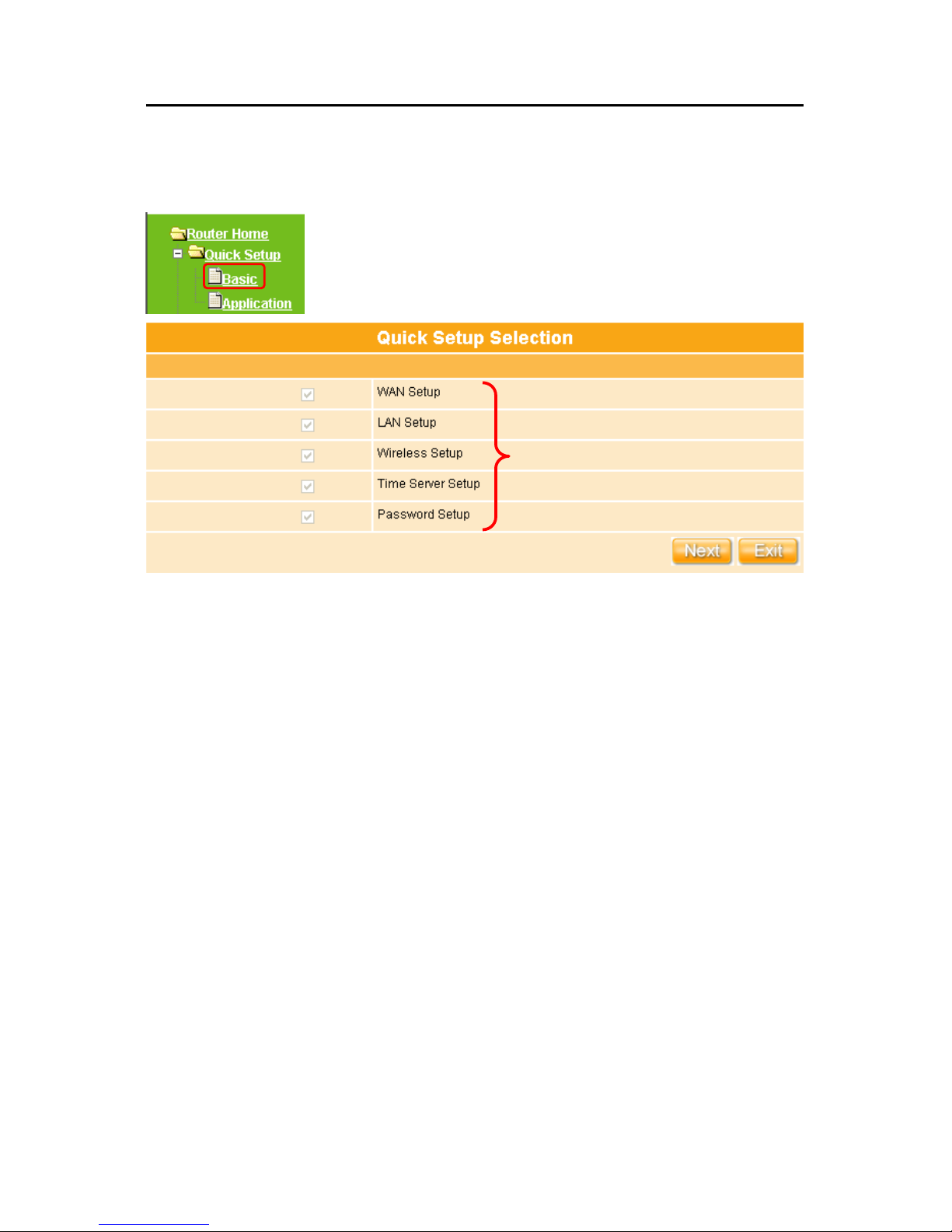
Quick Setup Basic Table List
Click “Basic” button to begin setup including WAN Setup、LAN Setup、Wireless Setup、
Time Server Setup and Password Setup.
Quick Setup of Basic instruction
WAN Setup: Setup the connecting type provided by your ISP, 4 modes of WAN
connection are supported by WE-1110 – Static IP, Dynamic IP, PPPoE, and PPTP.
LAN Setup: Setup the IP Address for LAN and Group. If you are using the Router with
multiple PCs on your LAN, you must connect the LAN via the Ethernet ports on the
built-in Ethernet switch. You must assign a unique IP address to each device residing
on your LAN.
Wireless Setup: Define the Wireless Mode, ESSID, TxRate, Channel and other
wireless settings.
Time Server Setup: Set system time by NTP or PC.
Password Setup: To change administrator’s password.
Default setting and has to be set
Page 30
30
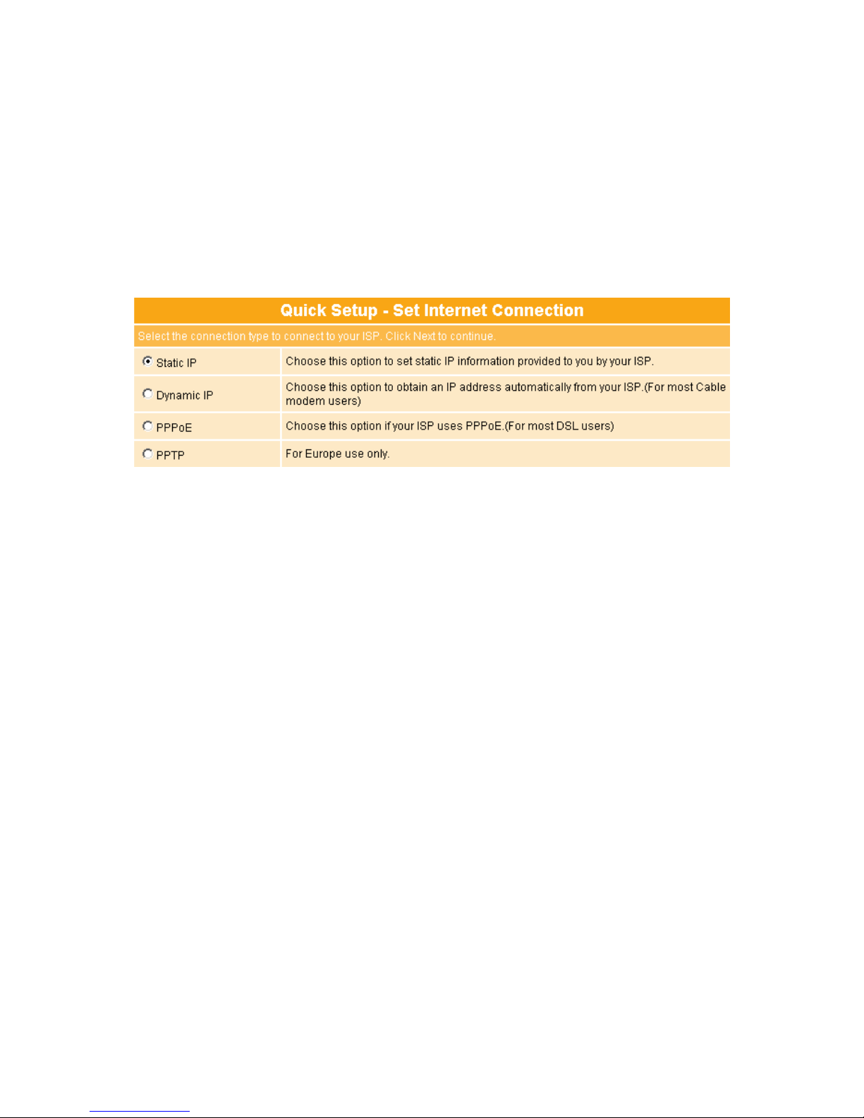
3.2.1 WAN Setup (Internet Connection)
WAN is short for Wide Area Network. The WAN settings can be referred to as the Public
setting. All IP information in the WAN settings is public IP addresses which are accessible
on the Internet. The WE-1110 supports 4 connection types to WAN. Select one of the WAN
connection modes required by your ISP in below Internet Connection Configuration page,
the WAN setting pages will differ depending on what kind of WAN Type you select.
Choose the WAN type under your demand for going to its setting part, which will show
under the above part of your chosen one.
See setup 3.2.1.1
See setup
3.2.1.2
See setup
3.2.1.3
See setup 3.2.1.4
Page 31

31
3.2.1.1 WAN Type – Static IP
Choose Static IP Address if all WAN IP information is provided to you by your ISP. You will
need to input in the IP address, IP Netmask and IP Gateway provided by your ISP. Each IP
address inputed in the fields must be in the appropriate IP form, which are four IP octets
separated by a dot (x.x.x.x). The Router will not accept the IP address if it is not in this
format. If ISP provided you DNS information, please select “Specify DNS Server IP”;
otherwise, select “No Default DNS Server”.
Please click on “Next” button to go to “3.2.2 LAN Setup”.
Necessary for Domain name enable
Key in information provided by ISP
Page 32

32
3.2.1.2 WAN Type – Dynamic IP
Choose Dynamic IP to obtain an IP address information automatically form your ISP. Select
this option if your ISP does not give you any IP numbers to use. This option is commonly
used for Cable modem services. If ISP provided you DNS information, please select
“Specify DNS Server IP”; otherwise, select “No Default DNS Server”.
Click on “Next” button to connect to “3.2.2 LAN Setup”.
MAC
address
Page 33

33
3.2.1.3 WAN Type – PPPoE
This option is typically used for DSL services. Choose PPPoE (Point to Point Protocol over
Ethernet) if your ISP uses PPPoE connection. Your ISP will provide you with a username
and password. MTU stands for Maximum Transmission Unit. For PPPoE connections, you
may need to change the MTU setting in order to work correctly with your ISP. As Idle Time,
it’s the amount of time of inactivity before disconnecting your PPPoE session. Input an Idle
Time (in minutes) to define and period of time for which the Internet connection is
maintained during inactivity. If the Auto-reconnect enabled, the Router will automatically
connect to your ISP after your system is restarted or if the connection is dropped. If ISP
provided you DNS information, please select “Specify DNS Server IP”; otherwise, select
“No Default DNS Server”.
Click on “Next” button to connect to “3.2.2 LAN Setup”.
Key in User Name provided by ISP
Key in Password provided by ISP
Page 34

34
3.2.1.4 WAN Type – PPTP
This option is typically used for DSL services. Some DSL service providers supply a special
DSL modem. This kind of modem only supports the PPTP tunnel to access the Internet,
you should create a PPTP tunnel that carries a PPP session and terminates on the DSL
model. Once the tunnel has been established, this kind of DSL modem will forward the PPP
session to the ISP. As long as the PPP session is connected, all the local users will be able
to share this PPP session to access to the Internet. If ISP provided you DNS information,
please select “Specify DNS Server IP”; otherwise, select “No Default DNS Server”.
Please input the account’s information of Account and Password which provided by your
ISP, and then click on “Next” button to connect to “3.2.2 LAN Setup”.
Necessary to key in
Necessary to key in
Page 35

35
3.2.2 LAN Setup
If you are using the WE-1110 with multiple PCs on your LAN, you must connect the LAN via
the Ethernet ports on the built-in Ethernet switch. You must assign a unique IP address to
each device residing on your LAN. The LAN IP address identifies the router as a node on
your network; that is, its IP address must be in the same subnet as the PCs on your LAN.
The default LAN IP for the Internet Security Router is 192.168.1.1.
For Gateway IP Address, the IP address 192.168.1.xxx (xxx can be any number between 1
and 254 that is not used by another device.) Please don’t change the default LAN IP
settings at this section until you have completed the reset of the configurations and confirm
that your Internet connection is working. And the DHCP Server will automatically allocate
an unused IP address from the IP address pool to the requesting computer. You must
specify the starting and ending address of the IP address pool.
Click on “Next” button to proceed to the next setting.
The setup of pre-assigned Gateway
IP Address is
suggested for good to
use.
Requested to be as
complied as LAN IP
.
Page 36

36
3.2.3 Wireless Setup
WE-1110 is based on industry standards to provide compatible high-speed wireless
connectivity within your home, business or public access wireless networks. Strictly
adhering to the IEEE standard, the router will allow you to access the data you want, when
and where you want it. You will be able to enjoy the freedom that wireless networking
delivers.
For selecting configuration utility in AP/Bridge wireless connection, the Channel 6 is the
default channel; all devices on the network must be set to the same channel to
communication on the network. The default TxPreamble setting is Long. Authentication is
the security function to prevent the connection requests from unauthorized wireless clients.
As the Encryption Type, select WEP or WPA can protect your data from eavesdroppers, if
you do not need the encryption, select “None” to skip the following setting.
For selecting configuration utility in WDS wireless connection, please refer to “3.3.3
Wireless” for detail setting.
After checking each above blank and choose the suitable item as your demand, click on
“Next” button to proceed to next setting.
Notice: If use AP/Bridge to do wireless connection to router, here suggest disable the
DHCP setup in LAN Setup, please refer to “3.3.2 LAN”.
Select
AP/Bridge
or WDS
You can use the default ESSID
unless more than one
AP/Router is deployed in the
same area. And it will show
when searching the wireless
signal
Page 37

37
3.2.4 Time Server Setup
The section provides to change the Time. The Router keeps a record of the current date
and time, which is used to calculate and report various performance data, but changing the
router’s date and time does not affect the date and time on your PCs.
Select your time zone from the “Time Zone” drop-down list, or you may set the time by
manual; there is no real time clock inside the router, the system date and time are
maintained by external network time server.
3.2.5 Password Setup
Here suggest changing the password for logging into the configuration manager under
security reason.
For changing password, please fills the password information into above blanks, and then
The password may consist of
A-Z, a-z, 0-9, underscores, and a
single dot (.)
Page 38

38
clicks on “Next” button.
Notice 1: Only the password can be changed, the user name for administrator is “admin”
and is not allowed to be changed.
Notice 2: If you forget administrator’s password, please reset the WE-1110 to default setting
by pushing the “Reset” button on the rear panel for 5 seconds. And the
password will return to “admin”.
Quick Setup Application Table List
Click “Application” botton to begin setup including USB Disk Management Setup, User
Account Management Setup, Firewall Setup, QoS Setup, FTP Server Setup, Web
Camera Setup, Printer Server Setup, Samba Server Setup and Audio Server Setup.
Default setting and has to be set.
Default setting and has to be set.
Page 39

39
3.2.6 USB Disk Management Setup
Easy to check all the USB storage devices connected to your WE-1110, view the entire
data folder inside each storage devices, and you can do the disk formatting via click on the
button in this page.
Select the USB Disk and click on “OK” button for refresh all disks before you do disk
partition, and the “Unplug” button will appear. To partition/format the disk, please select the
disk and click on “Format” button. Moreover, if you want to view the data inside the disk,
please go to “3.2.10 FTP Sever Setup” to enable FTP server and then click on “Disk
Explorer” to view all disks folder inside the device.
Notice: You have to click on “Unplug” button before remove the USB devices from
WE-1110.
Page 40

40
3.2.7 User Account Management Setup
Personal users can use each individual application such as My Status, My Webcam and My
Document. This section is to set the user’s right. Also, all the users right will be showed in
User Account List and can do the edit or delete by clicking the meaning text.
Input the user’s name and password, and then click on “Add”, and you will see the user
information appear on the “User Account List”.
Set each user’s right and space arrangement, then click on “Add” button for saving user’s
setting, and click on “Next” button after finish.
Page 41

41
3.2.8 Firewall Setup
The Firewall rules of WE-1110 are an advance feature used to deny or allow traffic from
passing through the router.
The default setting for Firewall Protection Level security is in Low Level, which Attacks
Blocking Policy, allow all Inbound and Outbound IP Filter Policy, and allow all router service
access policy from WAN; please change it as your demand.
And click on “Next” button to next step.
Page 42

42
3.2.9 QoS Configuration Setup
QoS management helps to set and evaluate QoS policies and goals. It is the particular
concern for the continuous transmission of high-bandwidth video and multimedia
information. Transmitting this kind of content dependably is difficult in public networks using
ordinary best effort protocols.
Make sure your connecting bandwidth with ISP and set the Priority percentage. Once
setting the QoS service, the transmitting performance will be affected, so please ensure
your connecting setting before doing this setup.
Click on “Next” button to next step after finish above setting.
Input the figures under your demand to
decide the priority order you want
Page 43

43
3.2.10 FTP Server Setup
WE-1110 can be the FTP Server provides users to transmit files, also for the guest can
download the files from assign website. Moreover, by connecting USB HDD, USB Flash to
the router, user can easily set up a FTP Server to share or download files for local or
remote users.
If the USB device (HDD or Flash) isn’t setup first, you can’t enable the FTP Server.
Set the FTP Server and related setting. Disable the function as demand, and click on
“Next” button to continue.
Page 44

44
3.2.11 Web Camera Server Setup
If you plan to use the WE-1110 as a Web Camera site, connect a supported USB Web
Camera to the USB port of the WE-1110. To enable the webcam server and access from
WAN as demand, and the Image format can be selected.
Make sure the webcam already connected to WE-1110, and then select “Enable” the
function under your demand and situation.
Click on “Next” button to connect to next step.
Notice: Before webcam server enable, please make sure the webcam had connected to the
WE-1110, otherwise, the “Enable” selection can’t be checked.
Page 45

45
3.2.12 Printer Server Setup
WE-1110 supports Multi-Function Printer (MFP) such as HP2610, supported features
including printer, scanner, and cardreader. Scanner Server and Cardreader Server will be
shown as Enable, therefore users can use MFP features form LAN.
Enable these servers on your demand and click on “Next” button to connect to next setup.
Notice: After above Printer Server in Quick Setup finish, the related printing setting on
WE-1110 and PC have to be set also. Please refer to “3.5.3 Printer / MFP Server”
to set the detail printer setting.
Notice:Only supports HP and EPSON series Scanner.
If the printer isn’t connected,
you can’t choose “Enable”.
Page 46

46
3.2.13 Samba Server Configuration Setup
Samba is a software package that gives network administrators flexibility and freedom in
terms of setup, configuration, and choice of systems and equipment.
Support NetBIOS protocol, the consumer sharing file and printer which provides as the My
Network Places.
Click on “Next” button to connect to next step.
3.2.14 Audio Server Setup
Make use of a speaker with the adapter connectivity attached, can broadcast music directly
through the LAN.
Click on “Next” button to connect to next step.
Page 47

47
3.2.15 Quick Setup Finish
Below screen will be shown when the Quick Setup is completed successfully.
To apply your new settings, please click on “Finish” button to reboot system automatically
and goes to the Product’s Diagram Homepage. You may connect to Internet via wire or
wireless at this moment according to above settings.
Page 48

48
3.3 IP Config
This function allows you to add routing rules into WE-1110. It is useful if you connect several
computers behind WE-1110 to share the same connection to Internet.
3.3.1 WAN
Select WAN under the IP Config menu. WE-1110 supports four WAN connection types, i.e.
Static IP, Dynamic IP, PPPoE and PPTP. Follow the instructions to enter the WAN setting
page.
3.3.1.1 Static IP
The WAN (Wide Area Network) page shows the settings that are used to connect to your ISP
(Internet Service Provider). Please select the Static IP for your specific ISP.
If you applied for a Static IP connection type from ISP, please follow the steps to setup your
WAN connection.
1. IP Address
Input your IP Address supplied by ISP. If you don’t know, please check with your ISP.
Page 49

49
2. Subnet Mask
Input your Subnet Mask supplied by ISP
3. IP Gateway
Input your IP Gateway Address. If you don’t know, please check with your ISP.
4. DNS
If ISP provided you DNS information, please select “Specify DNS Server IP” and input
the DNS information into the blank; otherwise, select “No Default DNS Server”.
5. Apply & Cancel
Click on Apply button to continue. Click on Cancel button to clean the setting on this
page.
3.3.1.2 Dynamic IP
If you applied for a Dynamic IP connection type from ISP, please follow the steps to setup
your WAN connection. Cable modem providers typically use dynamic assignment of IP
Address.
1. Host Name
The host name is optional; but if your ISP requires you to input a specific host name,
please input it in, for example WE-1110 applied for from ISP. Generally, Cable Modem will
provide the hostname information.
Page 50

50
2. MAC Address: Keep, Clone & Input MAC Address
Select Keep or Clone MAC Address for copying the MAC address of your Ethernet
adapter to the gateway, or input a group of MAC Address. Generally, your ISP will
remind you.
3. DNS
If ISP provided you DNS information, please select “Specify DNS Server IP” and input
the DNS information into the blank; otherwise, select “No Default DNS Server”.
4. Apply & Cancel
Click on Apply button to continue. Click on Cancel button to clean the setting on this
page.
3.3.1.3 PPPoE
If you applied for a PPPoE connection type from ISP, please follow the steps to setup your
WAN connection.
1. User Name
Input your User Name supplied by ISP. If you don’t know, please check with your ISP.
2. Password
Page 51

51
Input your Password supplied by ISP.
3. MTU
MTU stands for Maximum Transmission Unit. For PPPoE connections, you may need to
set the MTU setting in order to work correctly with your ISP.
4. Idle Time
The time of inactivity before disconnecting your PPPoE session. Input an Idle Time (in
minutes) to define a maximum period of time for which the Internet connect is maintained
during inactivity. If the connection is inactive for longer than the defined Idle Time, then
the connection will be dropped. Either set this to zero or enable Auto-reconnect to
disable this feature.
5. Auto-reconnect
If enabled, the Router will automatically connect to your ISP after your system is
restarted or if the connection is dropped.
6. DNS
If ISP provided you DNS information, please select “Specify DNS Server IP” and input
the DNS information into the blank; otherwise, select “No Default DNS Server”.
7. Apply & Cancel
Click on Apply button to continue. Click on Cancel button to clean the setting on this
page.
3.3.1.4 PPTP
If you applied for a PPTP connection type from ISP, please follow the steps to setup your
WAN connection.
Page 52

52
1. PPTP
Select connect to PPTP by on demand, Always Online or Manual connects.
2. PPTP Account
Input the PPTP Account supplied by ISP. If you don’t know, please check with your ISP.
3. PPTP Password
Input the Password supplied by ISP.
4. Retype your Password
Retype the password into this blank for confirming.
5. PPTP Server IP
Input the Server IP supplied by ISP. If you don’t know, please check with your ISP.
6. My WAN IP
Input the WAN IP address provided by your ISP.
7. My WAN Subnet Mask
Input the WAN Subnet Mask supplied by your ISP. If you don’t know, please check with
your ISP.
Page 53

53
8. MTU
MTU stands for Maximum Transmission Unit. For PPTP connections, you may need to
set the MTU setting in order to work correctly with your ISP.
9. Idle Time
The time of inactivity before disconnecting your PPTP session. Input an Idle Time (in
minutes) to define a maximum period of time for which the Internet connect is maintained
during inactivity. If the connection is inactive for longer than the defined Idle Time, then
the connection will be dropped. Either set this to zero or enable Auto-reconnect to
disable this feature.
10. DNS
If ISP provided you DNS information, please select “Specify DNS Server IP” and input
the DNS information into the blank; otherwise, select “No Default DNS Server”.
11. Apply & Cancel
Click on Apply button to continue. Click on Cancel button to clean the setting on this
page.
3.3.2 LAN
Use this page to set up the local IP address and subnet mask for your router. Please select
LAN under the IP Config menu and follow the instructions below to enter the LAN setting
page to configure the settings you want.
Page 54

54
1. IP Address
The default value of LAN IP address is 192.168.1.1 for this router.
2. IP Netmask
Input Subnet Mask, normally it is 255.255.255.0.
3. DHCP
Enable or Disable DHCP services. The DHCP server will automatically allocate an
unused IP address from the IP address pool to the requesting computer if Enabled.
4. Start IP
This field specifies the first address in the pool to be assigned by the DHCP server in your
local network. Default setting is from 2.
5. End IP
This filed specifies the last address in the pool to be assigned by the DHCP server in your
local network. The default setting is end of 253.
6. Advanced
Enable the advance setting and then setup the Router, DNS and WINS value.
Page 55

55
7. Router
This field indicates the IP address of Router to provide to clients that request IP Address
from DHCP Server, the default setting is the same with LAN IP address.
8. DNS
This field indicates the IP address of DNS to provide to clients that request IP Address
from DHCP Server, the default setting is the same with LAN IP address.
9. WINS
The Windows Internet Naming Service manages interaction of each PC with the Internet.
If you use a WINS server, input IP Address of server here.
10. Apply & Cancel
Click on Apply button to continue. Click on Cancel button to clean the setting on this
page.
Besides, the DHCP information will be listed below above setting in DHCP Clients, including
IP Address and MAC address.
3.3.3 Wireless
The WE-1110 enables fastest 54 Mbps IEEE802.11g wireless transmissions and keeps
compatibility with existing IEEE 802.11b devices. The WE-1110 complies with IEEE 802.11b
standard. Please select Wireless under the Main menu. Follow the instructions to enter the
Wireless setting page to configure the settings you want.
Page 56

56
1. Wireless
Select AP/Bridge or WDS to allow or disallow the wireless operation.
2. Wireless Mode
This field indicates the 802.11g interface mode. “802.11G” prevents the 802.11b clients
from accessing the router. “802.11B/G” allows both 802.11b and 802.11g clients to
access the router. “802.11B” will enable the network as an 802.11b wireless network. By
default, the Mode is “802.11B/G”.
3. ESSID
You can use the default ESSID and radio channel unless more than WE-1110 or Access
Point is deployed in the same area. Under this situation, you should use a different
ESSID and radio channel for each WE-1110 or Access Point. All WE-1110 and your
wireless LAN card must have the same ESSID to allow a wireless mobile client to roam
between WE-1110s. By default, the ESSID is set to “MFP_Server_Router”.
4. TxRate
Select the transmission rate for the network. The default setting is Auto.
5. Channel
IEEE 802.11g and 802.11b devices are direct sequence spread spectrum devices that
spread a radio signal over a range of frequencies. The range of frequencies used by a
Page 57

57
direct sequence device is called Channel.
The 802.11g and 802.11b specification supports up to 14 overlapping Channels for radio
communication. But only 11 Channels are supported in the United States and therefore
on WE-1110. To minimize interference, configure each WE-1110 to use Non-overlapping
channels. Non-overlapping channels have 25 MHz separation beginning at the first
allowed channel for the country (for the US and most of Europe, channel 1, 6 & 11 are
used.)
Make sure that WE-1110 sharing the same Channel (or Channels close in number) is as
far away from each other as possible, based on the results of your site survey of the
facility. You can find the site survey utility in WE-1110’s setup CD. By default, the channel
is “6”.
6. Hide SSID
This term is used to increase the security level. Check it to hide SSID information against
the wireless clients that are sniffing radio. By default, this option is inactive.
7. TxPreamble
The default TxPreamble setting is Long.
8. Beacon Interval
Beacons are packets sent by an access point to synchronize a wireless network. Specify
a beacon interval value. Default (100) is recommended.
9. RTS Threahold
This value should remain at its default setting of 2346. If you encounter inconsistent data
flow, only minor modifications to the value range between 256 and 2346 are
recommended.
10. Authentication Mode
Four authentication methods are supported: Open and Shared. Select Open, your
wireless network would be intruded by anonymous. Not only your network bandwidth
would be shared; but also transmitting data might be intercepted. Select Shared function
and it can be taken effect.
Page 58

58
11. Encrypt Type - WEP
There are two types of encrypt type can be selected, including WEP and WPA.
WEP Encryption: Enabling WEP can protect your data from eavesdroppers. If you
do not need this feature, select “None” to skip the following setting. The WE-1110
supports both 64-bit and 128-bit encryption using the Wired Equivalent Privacy (WEP)
algorithm. Select the type of encryption you want to use (64 or 128 bit) and configure
one to four WEP Keys. The “128-bit” method is more secure than the “64-bit”.
Key Type: For 64bits WEP key, either 5 ASCII characters or 10 hexadecimal digitals
can be inputed. For 128bits WEP key, either 13 ASCII characters or 26 hexadecimal
digits can be inputed.
Note: 128 bits WEP is most secure, but has more encryption/decryption overhead. Note
that all wireless devices must support the same WEP encryption bit size and
have the same key. Four keys can be inputed here, but only one key can be
selected at a time. The keys can be inputed in ASCII or Hexadecimal. Select the
item from drop-down list you wish to use.
Pass phrase: Automatically generate four WEP keys. A WEP key is either 10 or 26
hexadecimal digits (0~9, a~f, and A~F) based on whether you select 64 bit or 128 bit
in the WEP drop-down menu. Type a combination of up to 64 letters, numbers, or
symbols in the blank, the WE-1110 uses an algorithm to generate four WEP keys for
encryption. If you want to type in the keys manually, leave this filed blank.
Note: This function eases users from having to remember their passwords. But this isn’t
as secure as manual assignment.
WEP Key: At most four keys can be set. A WEP key is either 10 or 26 hexadecimal
digits (0~9, a~f, and A~F) based on whether you select 64 bit or 128 bit in the WEP
drop-down list. The WE-1110 must have at least the same default key.
Page 59

59
12. Encrypt Type - WPA
The WPA encrypts each frame transmitted from the radio using the pre-shared key (PSK)
which inputed from this panel or a key got dynamically through 802.1x.
WPA-PSK (TKSP): Allow the access from WPA clients simultaneously and the
encryption keys are given from PSK respectively.
WPA Rekey Timer: Allows for the session keys to be refreshed over time, minimizing
the amount of data that is encrypted with the same session key.
ASKII: The 8~63 ASCII characters can be inputed. For example
“0123456789ABCD….”
Radius with 802.x: Check this circle to enable Radius client function.
WPA Rekey Timer: Allows for the session keys to be refreshed over time, minimizing
the amount of data that is encrypted with the same session key.
Page 60

60
RADIUS Server IP: The IP address of RADIUS server.
RADIUS Server Port: The UDP port number that the RADIUS server is listed. The
default value is 1812.
Shared Secret: The RADIUS server and client share a secret that is used to
authenticate the messages sent between them. You must configure both sides to sue
the same shared secret.
13. Apply & Cancel
Click on Apply button to save the settings. If you want to clean the settings, please click
on Cancel button. The functional button, Cancel can take effect after clicking on Apply
button.
3.3.4 DDNS
Dynamic DNS allows you to make an assumed name as a dynamic IP address to a static
hostname. Please configure the dynamic DNS below.
Please s
elect DDNS under the IP
Config menu, and follow the instructions below to enter the DDNS setting page to configure
the settings you want.
1. Service Provider
Choose correct Service Provide from drop-down list, here including dyndns, dhs, ods and
tzo embedded in the WE-1110.
Page 61

61
2. Enable / Disable DDNS
Select Enable to use DDNS function, each time your IP address to WAN is changed, the
information will be updated to DDNS service provider automatically.
3. Host Name
This field represents the Host Name you register to Dynamic-DNS service and expect to
export to the world.
4. User Name & Password
User Name and Password is used as an identity to login DDNS service.
6. Apply & Cancel
Click on Apply button to continue. Click on Cancel button to clean the setting on this
page.
3.4 Advance
There are NAT settings, Firewall setting and QoS setting included in Advance setting. The
Advanced setting is in Router Mode only.
3.4.1 NAT
NAT is a method of mapping one or more IP addresses and/or services ports into different
Page 62

62
specified services, where NAT stands for Network Address Translation. It allows the
internal IP addresses of many computers on a Local Area Network (LAN) to be translated
to one public address, saving users’ cost. It also plays a security role by obscuring the true
IP addresses of important machines form potential hackers on the Internet. For
convenience, we called a router having the NAT facility as a NAT-enabled router.
3.4.1.1 Virtual Server
To make services, like WWW, FTP, provided by a server in your local network accessible
for outside users, you should specify a local IP address to the server. Then, add the IP
address and network protocol type, port number, and name of the service in the following
list. Based on the list, the gateway will forward service request form outside users to the
corresponding local server.
Page 63

63
1. Enable Virtual Servers: Check “Enable” applies all those rules in Virtual Server List
into the WE-1110.
2. Description: Input the description of the virtual server, this filed allows you to record
what this rule is used for.
3. Private IP: Specify the private IP address of the internal host offering the service.
4. Protocol Type: Specify the transport layer protocol (TCP or UDP).
5. Private Port: Specify the private port number of the service offered by the internal host.
6. Public Port: Specify the public port number of the service in Internet.
7. Schedule: Setup the schedule for server.
8. Add: Click on “Add” button to record this setting.
9. Apply & Cancel
Click on Apply button to add the settings into the list table. Click on Cancel button to
clean the setting on this page.
10. Virtual Server List
Showing all Virtual Server information, and can process Edit or Cancel feature. Is
shown as diagram below
3.4.1.2 Virtual DMZ
Virtual DMZ (De-Militarized Zone) allows you to expose one computer to Internet, so that
all inbound packets will be redirected to the computer you set. It is useful while you run
some applications that use uncertain incoming ports. Please use it carefully.
Page 64

64
1. Enable/Disable Virtual DMZ: Check “Enable” applies Virtual DMZ for the Router.
2. IP Address: This field stands for the destination IP address that you like to redirect the
matched packet to.
3. Apply & Cancel
Click on Apply button to continue. Click on Cancel button to clean the setting on this
page.
3.4.2 Firewall
The Firewall function helps protect your local network against attack from outside. It also
provides a way of restricting users on the local network from accessing the Internet.
Additionally, it can filter out specific packets to trigger the router to place an outgoing
connection.
3.4.2.1 Firewall Configuration
The WE-1110 provides built-in firewall functions, enabling you to protect the system against
denial of service (DoS) attacks and other types of malicious accesses to your LAN while
providing Internet access sharing at the same time. You can also specify how to monitor
attempted attacks, and who should be automatically notified.
Page 65

65
1. Firewall Protection Level: Select the level from the drop-down list, including High,
Medium and Low. The below screen including SPI service and ICMP setting will
change according to your level setup.
2. Enable SPI Service: The WE-1110 often monitor a wider range of activity, such as
patterns of traffic and the type of application sending traffic. With SPI, the router looks
at individual packets for patterns similar to known hacker techniques, such as Denial of
Service (DoS) attacks, Ping of Death (illegal ping packet sizes or excessive ICMP
messages), SYN Flood, LAND Attack, and IP Spoofing. Enable it if you need.
3. Blocking ICMP Ping from WAN Side: The purpose of ICMP is to provide feedback
regarding the network and datagram, it is not to make IP a reliable transport
mechanism. ICMP messages use a basic IP datagram header with the IP data being
the ICMP message. The IP source address is that of the host or gateway sending the
ICMP message with the destination IP address being that of the original source IP
address. You can enable ICMP Ping from WAN side or not.
Page 66

66
4. DoS Attacks Blocking Settings
Enable DoS Attacks Blocking: The following sections will explain in more detail
about DoS Defense setup by using the web configurator. There are a total 8 kinds of
defense function for the DoS Defense Setup. By default, the DoS Defense
functionality is disabled. Further, once the DoS Defense functionality is enabled, the
default values for the threshold and timeout values existing in some functions are
set to 300 packets per second and 10 seconds, respectively. A brief description for
each item in the DoS defense function is shown below.
SYN Flooding: Check or uncheck this option to enable or disable protection
against SYN Flood attacks. This attack involves sending connection requests to a
server, but never fully completing the connections. This will cause some computers
to get into a “suck state” where they cannot accept connections from legitimate
users. (“SYN” is short for SYN chronize”; this is the first step in opening an Internet
connection). You can select this box if you wish to protect the network from TCP
SYN flooding.
WinNuke: Check or un-check this option to enable or disable protection against
WinNuke attacks. Some older versions of the Microsoft Windows OS are vulnerable
to this attack. If the computers in the LAN are not updated with recent
versions/patches, you are advised to enable this protection by checking this check
box.
Page 67

67
MIME Flood: Check or un-check this option to enable or disable protection against
MIME attacks. You can select this box to protect the mail server in your network
against MIME flooding.
FTP Bounce: Check or un-check this option to enable or disable protection against
FTP bounce attack. In its simplest terms, the attack is based on the misuse of the
PORT command in the FTP protocol. An attacker can establish a connection
between the FTP server machine and an arbitrary port on another system. This
connection may be used to bypass access controls that would otherwise apply.
IP Unaligned Time-Stamp: Check or un-check this option to enable or disable
protection against unaligned IP time stamp attack. Certain operating systems will
crash if they receive a frame with the IP timestamp option that isn’t aligned on a
32-bit boundary.
Sequence Number Prediction Check: For TCP packets, sequence number is
used to guard against accidental receipt of unintended data and malicious use by
the attackers if the ISN (Initial Sequence Number) is generated randomly. Forged
packets with valid sequence numbers can be used to gain trust form the receiving
host. Attackers can then gain access to the compromised system. Note that this
attack affects only the TCP packets originated or terminated at the Internet Security
Router.
Sequence Number Out of Range Check: Protect against TCP out of range
sequence number attacks. An attacker can send a TCP packet to cause an
Intrusion Detection System (IDS) to become unsynchronized with the data in a
connection. Subsequent frames sent in that connection may then be ignored by the
IDS. This may indicate an unsuccessful attempt to hijack a TCP session.
ICMP Verbose: Check or un-check this option to enable or disable protection
against ICMP error message attacks. ICMP messages can be used to fold your
network with undesired traffic.
Max IP Fragment Count: Input the maximum number of fragments the Firewall
should allow for every IP packet. This option is required if your connection to the
ISP is through PPPoE. This data is used during transmission or reception of IP
fragments. When large sized packets are sent via the WE-1110, the packets are
chopped into fragments as large as MTU (Maximum Transmission Unit). By default,
this number is set to 45. If MTU of the interface is 1500(default for Ethernet), then
Page 68

68
there can be a maximum of 45 fragments per IP packet. If the MTU is less, then
there can be more number of fragments and this number should be increased.
Minimum IP Fragment Size: Input the Minimum size of IP fragments to be allowed
through Firewall. This limit will not be enforced on the last fragment of the packet. If
the Internet traffic is such that it generates many small sized fragments, this value
can be decreased. This can be found if there are lots of packet losses, degradation
in speed and if the flowing log message is generated very often: “fragment of size
less than configured minimum fragment size detected”.
5. Apply & Cancel
Click on Apply button to continue. Click on Cancel button to clean the setting on this
page.
3.4.2.2 IP Filter
Use IP Filter to deny LAN IP addresses from accessing the Internet. You can deny specific
port numbers or all ports for the specific IP address.
1. Enable IP Filter: Check Enable or Disable to apply IP Filter function.
Page 69

69
2. Enable Log: All packets between WAN and LAN will be logged.
3. Source: To specify the appropriate IP address / mask and input the source port
number.
4. Destination: Allows you to set the destination address / mask to which this rule should
apply and input the source port number.
5. In/Out: Select Inbound or Outbound ACL (Access Control List) Rules, you can control
(allow or deny) incoming or external network access to computers on your LAN.
6. Protocol: This option allows you to select protocol type. Available settings are TCP,
UDP and ICMP.
7. Listen: To check if a computer is on the Internet. It sends ping packets and listens for
replies from the specific host.
8. Time Ranges: Apply IF Filter by setting Time ranges.
9. Action: Select Deny, the IP filter will deny for above time range, otherwise, to allow IP
filter in above time.
10. Side: Set the IP filter from LAN or WAN, or you may select both side.
11. Add, Apply & Cancel:
After finish above setting, click Add button to create the new ACL rule. Click on Apply
Page 70

70
button to add the settings into the list table. Click on Cancel button to clean the setting on
this page.
3.4.2.3 MAC Filter
Use MAC Filters to deny LAN computers by their MAC addresses from accessing the
Internet. You can manually add a MAC address that is currently connected to the WE-1110.
1. MAC Filter Action: To Deny or Allow all MAC Filter action.
2. Enable MAC Filter: Check Enable or Disable to apply MAC Filter function.
3. Enable Log: All packets between WAN and LAN will be logged.
4. Description: Input the filter description into this blank.
5. MAC Address: Input the MAC address manually that you want to filter.
Page 71

71
6. Time Ranges: Apply MAC Filter by setting time ranges.
7. Add, Apply & Cancel
After finish above setting, click Add button to create the MAC configuration rule. Click on
Apply button to add the settings into the list table. Click on Cancel button to clean the
setting on this page.
8. MAC Filter List
All MAC Filter information will be shown on the list, and can process Edit and Cancel
feature.
3.4.2.4 URL Filter
Keyword based URL(Uniform Resource Locator)filtering allows you to define one or more
keywords that should not appear in URL’s. Any URL containing one or more of these
keywords will be blocked. This is a policy independent feature i.e. it cannot be associated
to ACL rules. This feature can be independently enabled / disabled, but works only if
firewall is enabled.
Page 72

72
1. Enable URL Filter: Check Enable or Disable to apply URL Filter function.
2. Enable log: All packets between WAN and LAN will be logged.
3. Description: Input the filter description into this blank.
4. URL keyword: Input the URL key words into this blank to apply filter blocking, example:
“yahoo”, then it’ll block all the websites from yahoo range.
5. Time Ranges: Apply URL Filter by setting Time ranges.
6. Add, Apply & Cancel
After finish above setting, click Add button to create the URL rule. Click on Apply button to
add the settings into the list table. Click on Cancel button to clean the setting on this page.
Page 73

73
7. URL Filter List
All URL filter will be shown on the list, and can process Edit and Cancel feature.
3.4.3 QoS
Quality of Service (QoS) refers to the capability of a network to provide better service to
selected network traffic over various technologies, including Frame Relay, Asynchronous
Transfer Mode (ATM), Ethernet and 802.1x networks, and IP-routed networks that may use
any or all of these underlying technologies. The primary goal of QoS is to provide priority
including dedicated bandwidth, controlled jitter and latency (required by some real-time and
interactive traffic), and improved loss characteristics. Also important is making sure that
providing priority for one or more flows does not make other flows fail. QoS technologies
provide the elemental building blocks that will be used for future business applications in
campus, WAN and service provider networks. This chapter provides each setting of QoS.
1. Enable QoS Service: One checkbox appears to activate the QoS control function or
not. Click it to force the router to perform QoS control over traffic flows. By default, it’s
enabled.
2. Current Upstream Bandwidth: Allows you to set the upper bound of the port
forwarding rate. It will be of great value to minimize the impact on other users from one
user who would otherwise monopolize the network transmission bandwidth (e.g.
playing games or downloading large files).
Page 74

74
3. Priority: To limit the bandwidth consumed over a backbone link by FTP transfers or
give priority to an important database access. And below application can be selected
each items and distribute the priority level.
4. Application: Including FTP, HTTP, E-mail, Telnet, Voice, Games, IM and Video priority
setting.
5. Apply & Cancel
Click on Apply button to save the setting. Click on Cancel button to clean the setting on
this page.
3.5 Server
The WE-1110 provides FTP Server, Web Camera Server, Printer/MFP Server, Audio Server
and Samba Server application.
3.5.1 FTP Server
By directly connecting USB storage devices to any USB port, FTP server can be created
with simple configuration. FTP Server utility allows both local and remote users to upload or
download files, pictures or MP3 music form the same storage device in most easy and
Page 75

75
timely fashion. It is also cost effective where users do not need to purchase a dedicated PC
to set up a 24 hours FTP service.
Before configure FTP Server, please make sure the storage device is properly plug into any
USB port on the router and make sure this USB storage device is detected by the router.
1. Enable FTP Server: The Enable for FTP Server only can be selected when USB
storage device plugged.
2. Enable Anonymous to Login: Allow anonymous to login after check on Enable.
3. Enable FTP Access from WAN: Allow FTP access from WAN side by checking on
Enable for this item.
4. FTP Server Port: Define the FTP command transfer service port. If you want to change
this port number, remember to change the service port setting of your FTP client, also.
5. Idle connection Time-Out: When a specific time value is added, FTP Server will be
de-activated if it has no activity within the time limit.
While USB storage
device is connected,
FTP Server can be
selected as “Enable”
Page 76

76
6. Apply & Cancel
Click on Apply button to continue. Click on Cancel button to clean the setting on this
page.
7. User Account List
User Name、Status and Opened Directory/File can be shown on the list.
Notice: FTP server is compatible with FAT32 or EXT3 format USB storage device. In case
you need to format your USB storage device. Please always make sure the device
is formatted with FAT32 or EXT3 standard.
3.5.2 Web Camera Server
The WE-1110 has built-in Web Camera Server. By connecting web camera to the router, it
allows user to monitor their home or office from remote locations.
Page 77

77
3.5.2.1 Web Camera Server Basic Setting
1. Enable Webcam Server: Allow using this function for checking on Enable.
2. Access from WAN: Allow webcam can access from WAN side by checking on Enable
for this item.
3. Preview: Click on this button, you can preview the image from webcam.
4. Record Setting: Please see the detail advance setting in next page.
5. Apply & Cancel
Click on Apply button to continue. Click on Cancel button to clean the setting on this
page.
3.5.2.2 Web Camera Advanced Configuration
Click on “Record Setting” button, and the screen will appear as below.
Page 78

78
1. Enable save image: If you want to save the image from webcam, please check on
Enable.
2. Save image interval: For saving image, you can set the save interval time, the default
value is 5 seconds.
3. Save Location: Set the save location for webcam image, you may save into USB HDD
or Remote FTP; if select save to Remote FTP, please continue following remote FTP
setting.
4. USB HDD Directory: The section provides option of which folder should be used for
saving webcam image.
5. Remote FTP URL: Input the FTP URL for saving webcam image.
6. Remote FTP port: Input the FTP port number under URL to save image.
7. Remote FTP user: Input the user’s name you like and it will be used to save the
webcam image into the FTP server.
8. Remote FTP password: Input the remote password.
Page 79

79
9. Remote FTP Directory: To provide option of which folder should be used for saving
webcam image.
10. Back: Click on Back button for returning to Webcam Basic Setting screen.
11. Apply & Cancel
Click on Apply button to continue. Click on Cancel button to clean the setting on this
page.
3.5.2.3 Application for Web Camera
3.5.2.3.1 Web Camera Monitoring Application
Monitor your home with a Webcam via WE-1110. Take pictures via WE-1110, also can do
the monitoring or recording all images into the USB HDD for reviewing. Often marketed as
surveillance tools for home or office security, network Webcams are now being employed
by early adopters for more personal matters, such as watching kids and monitoring pets.
The Webcam can be remotely accessed and controlled via a browser. Besides, to record
and monitor live action with USB webcam, also can view the image through Internet
browsers or WiFi mobile phones.
Page 80

80
3.5.2.3.1.1 Web Camera Monitoring via WAN connecting
For viewing the image via webcam from WAN connecting, below is the diagram.
How to check your WAN IP address
To monitor the image via webcam from outside door, you need to now the WAN IP address.
Select “Network Configuration” under Log & Status in main Menu after connection, and
you will see the WAN IP Address which used to connect to webcam screen. Here use
192.168.1.110 as example.
Page 81

81
Monitor the image via webcam from WAN
Input the WAN IP Address (as you see in above screen) into browser blanks, and you will see
the personal account login screen appear then input your own user account and password.
After login by personal, your will see the personal control panel screen as below, please click
on “My Webcam”.
There will be a pop-up screen showing the image from web camera as below example.
Page 82

82
3.5.2.3.1.2 Web Camera Motoring via WiFi mobile phone
Also, you may view the monitor live action through WiFi mobile phones.
Please key in the WAN IP address plus “/webcam.html” (ex:
http://210.64.134.25/webcam.html
) into the mobile phone’s browser blank and you will see
the webcam user login screen appeared.
Page 83

83
After login by your own account, you will see the monitor image from web camera via WiFi
mobile phone.
3.5.2.3.2 Web Camera Recording
3.5.2.3.2.1 Administrator Setting
WE-1110 also can record the pictures from Webcam; only Administrator can do the settings.
Select Web Camera Server from main Menu and Enable this function, click on Record
Setting button for further setting.
Page 84

84
To setup the Webcam Advanced Configuration for each blank, and the image from webcam
will be recorded into your USB HDD or Remote FTP, please refer to User’s Manual for the
detail setting. Click on Apply after setup finish.
For administrator, you may view all the images from webcam recording, please select Folder
Management and click on Disk Explorer to view entire folder inside the disk including
webcam record files.
Page 85

85
After click on Disk Explorer, you will see the folder screen appear including all the folders
inside the WE-1110. (Below is the example.)
All the image files will be saved in the folder “webcam_recorded_files”, please open the file
for checking.
Page 86

86
3.5.2.3.2.2 Personal Application
All the users under administrator’s setting can view entire webcam recording images from My
Document. Please login by your own personal account. For viewing your own folder, please
click on “My Document”.
After click on “My Document”, you will see below folder screen appeared.
Notice: If you can’t open the folder inside the FTP server, please check with administrator to
setup your FTP & Webcam’s right.
Page 87

87
3.5.3 Printer / MFP Server
The NES Mini Server Router with MFP has two USB ports for connection with printers to be
shared on the local area network. Follow the below steps to setup your PC to connect to a
Printer/MFP server.
1. Enable Printer Server: Check Enable for applying printer server.
2. Enable Printer Access From WAN: Allow printer can access from WAN side by
checking on Enable for this item.
3. Printer Model: The printer model will be shown when plug the USB printer.
4. Printer Name: Input the name of printer you like.
5. Printer Description: Input the description of printer as your demand.
Page 88

88
6. Apply & Cancel
Click on Apply button to continue. Click on Cancel button to clean the setting on this
page.
Besides above setting finished, the printer setting on PC also needs to be set as follows.
3.5.3.1 Printer Setting on PC
After Enable Printer Server in Quick Setup and Printer Server Configuration, please follow
below steps to set the detail LPR settings in your PC. (Below example is for Windows XP
platform.)
Step 1:
After setting USB printer in WE-1110’s setting screen, please go to
Start > Printers and Faxes to add a printer.
Then, please pay attention to the next steps. It points out only the important settings.
Page 89

89
Step 2:
Click “Add a printer”
Step 3:
Click “Next”
Page 90

90
Step 4:
Click the “Local printer attached to this computer”, and then click “Next”
Step 5:
Click the “Create a new port” and select the “Standard TCP/IP Port”, and then click “Next”
Page 91

91
Step 6:
Click “Next”
Step 7:
Input the IP address of WE-1110: 192.168.1.1 (Router Mode), and then click “Next”
Page 92

92
Step 8:
Select the “Custom” and click the “Settings”, and then click “Next”
Step 9:
Select “LPR” and give it the same “Queue Name” as USB Printer Name as shown, and
mark “LPR Byte Counting Enabled”. Finally, click on “OK” button.
Page 93

93
Step 10:
Click the “Finish”
Step 11:
Select the “Manufacturer” and “Printers”. If your printer doesn’t listed in the table, please
install its driver CD and then click on “Have Disk…” button for installation. Or click on
“Next” button to finish the setting.
You can name your printer, set it as default printer and share your printer in the next
screens, the Printer Server setting is getting finally.
Page 94

94
Step 12:
Click on Finish button and all steps of setting printer server are completely.
3.5.3.2 How to scan via scanner
If use the function of scanner, as long as is the software which supports scanning all can
open the picture of scanning, take “Word” as an example as follows
Step 1:
Click “Insert” > selected “Picture” > click on “From scanner or camera” to next step.
Step 2:
Appear a message window; please click on “Custom Insert” button.
Page 95

95
Step 3:
Set up each field value according to the demand, after complete setting, please click on
“Scan” button to scan picture.
Page 96

96
1. Image Type
Include three image type: “Black & White”, “Grayscale”, and “Color(RGB)”.
2. Media
Set up the media is “Reflective” or “Transparent”.
3. Mode
Please select your operation mode of WE-1110.
4. Scan Area
Set up width and height of scan area.
5. Server IP/Name
Different operation mode have different server IP of WE-1110.
6. Offset
Set up the picture skew left side and size of the top.
7. Resolution
Set up the dpi.
8. Auto Document Feeder((((ADF))))
If it is the paper feed type scanning machine, please enable the field.
3.5.4 Audio Server
Make use of a speaker with the adapter connectivity attached, can broadcast music directly
through the LAN.
1. Enable/Disable Music
Enable or disable this function.
Page 97

97
2. Apply & Cancel
Click on Apply button to finish setting. Click on Cancel button to clean the setting on
this page.
3.5.5 Samba Server
Support NetBIOS Protocol, the consumer sharing file or printer which provides as the “My
Network Places”.
1. Enable Samba Server
Enable or disable this function.
2. Workgroup Name
Input the workgroup name, default is “WORKGROUP”.
3. Server Name
Input the server name, default is “WE1110”.
4. Server Description
You can input description of the server, default is “SAPIDO WE-1110!”.
Page 98

98
5. Apply & Cancel
Click on Apply button to finish setting. Click on Cancel button to clean the setting on
this page.
3.5.5.1 How to enter the sharing floder
Please follow below step.
Step 1:
Please click the “start”, and select “My Computer”.
Step 2:
In the Address blank input the IP address: \\192.168.1.1.
Step 3:
Appearing a window request inputs user name and password, if is an administrator, please
input "admin"; If is personal consumer, please input personal account password, then
press the "OK".
Page 99

99
Step 4:
Appear following menu, can open following to share internal data.
Note: The most meetings appear four icons.
1. If connected USB flash or HDD, and then enable samba server function, it will appear a
samba folder.
2. If connected USB printer or MFP, and then enable printer server function, it will appear a
printer icon.
3. If the MFP include card reader, and then enable card reader server function, it will appear
the “User Disk” folder.
Page 100

100
3.6 System management
The NES Mini Server Router with MFP provides system management including Reboot,
Change Password, Firmware Upgrade, Driver Upload, Profile Save, Remote Management,
Time, UPnP Setting, User Account Management, Folder Management and Email Alert
setting. Following is each setting.
3.6.1 Reboot
If you had inputed the wrong configuration while setting up your router or other utilities, you
can always reboot your WE-1110 by this setting.
It’s necessary to reboot the router if it begins working improperly, please click on Reboot
button to reboot the router.
 Loading...