


Sapido Technology Inc. www.sapido.com.tw
1
SH106+
User Manual
V2.2.X iOS System
Smart Home System
Security + Power Saving Solution
Product Introduction:
SH106+ is a Smart Home Total Solution and easy to install in your home. Through Sapido APP, you can
remote control the security system, monitor your house, turn on/off the electronic appliances, and
receive instant push notification when something wrong with your home.
Sapido Smart Home System makes you live easier and do less, and more details please reference the
SH106+ User Manual.

Sapido Technology Inc. www.sapido.com.tw
2
Catalogue
1. Hardware Instruction and Introduction ............................................................................................ 5
1.1 LED guide-light indicator ................................................................................................... 5
1.2 Hardware Instruction...................................................................................................... 10
1.3 Hardware Installation ..................................................................................................... 15
1.3.1 Wi-Fi Application Instruction ………………………..……………….………………………………….………15
1.3.2 Wired & Wi-Fi Application Instruction .……..………………….………………..………..……………….24
2. APP Download and Network Setup (iOS system) .......................................................................... 324
2.1 Wi-Fi Connection Way for APP Installation ...................................................................... 32
2.2 Both Wi-Fi & Wired Connection for APP Installation…………………………………………………….…40
3. Internet Settings ........................................................................................................................... 48
4. Security System Application .......................................................................................................... 51
4.1 Door & Window Sensor (DDLA0z) ..................................................................................... 52
4.2 Cloud Motion Sensor (MDKA0z) ....................................................................................... 58
5. Instruction of Security Alarm Router (WDG71n) ............................................................................... 65
5.1 Sound Sensor ................................................................................................................. 66
5.2 Temperature Sensor ..................................................................................................... 700
5.3 Light Sensor .................................................................................................................. 755
6. Application of IP Camera ............................................................................................................... 81
6.1. Surveillance Recording and Browse ................................................................................ 81
6.1.1. Real-Time Recording .................................................................................................. 81
6.1.2. Personalized Recording Schedule ............................................................................... 84
6.2. Real-Time Screenshot and Browse .................................................................................. 88
6.3. Music Play ...................................................................................................................... 90
6.3.1 Add the music to USB drive of IP Camera ................................................................... 90
6.3.2 Play music in USB drive .............................................................................................. 91
6.3.3 Schedule Setup of Music Play .................................................................................... 93
6.4. Setup for Alarm Siren ..................................................................................................... 96
6.4.1 Add the siren alarm to IP Camera’s USB ..................................................................... 96
6.4.2 Schedule Setup for Alarm Siren .................................................................................. 97
7. Smart Switch Application Instruction ............................................................................................. 100
7.1 Cloud Switch APP On/Off and Schedule Set-up ................................................................ 101
7.1.1 Set up Schedule of Power On/Off .............................................................................. 101
7.1.2 Schedule Setting ....................................................................................................... 104
7.1.3 Electricity Statistics ................................................................................................... 109
7.1.4 History ..................................................................................................................... 110
8. How to add Family Users to the SH106+ ....................................................................................... 111
8.1 Advice: When the family user’s handheld device is around the same place as SH106+ ... 111

Sapido Technology Inc. www.sapido.com.tw
3
8.2 When the family user’s handheld device is not around the same place as SH106+ ......... 114
9. Advanced Settings of SH106+ ...................................................................................................... 115
9.1 How to mute the alarm and the message notification ...................................................... 115
9.1.1 ZigBee Cloud Motion Sensor (MDKA0z) ...................................................................... 115
9.1.2 ZigBee Door & Window Sensor (DDLA0z) ................................................................... 116
9.2 How to change the security alarm sound ......................................................................... 117
9.2.1 ZigBee Cloud Motion Sensor (MDKA0z) ...................................................................... 117
9.2.2 ZigBee Door & Window Sensor (DDLA0z) ................................................................... 120
10. Application for Media Storage ..................................................................................................... 123
10.1 Upload the files in mobile device to IP Camera USB drive .............................................. 123
10.2 File download from USB drive of IP Camera .................................................................. 126
10.3 Directly stream the files of USB drive in mobile device .................................................. 129
11. Network Security ........................................................................................................................ 131
11.1 Network Security – Network security setup and internet device control ........................ 131
11.1.1 Client List ................................................................................................................ 131
11.1.2 2.4G Wireless Schedule ..………………………………….……………………………………………………..135
11.1.3 5G Wireless Schedule ………………………………………………………………………………………..137
11.1.4 Keyword Blocked ..................................................................................................... 137
11.1.5 Website History ....................................................................................................... 141
11.1.6 Distributed Denial of Service (DDoS) .......................................................................... 144
11.1.7 Login History ........................................................................................................... 144
11.2 Download List – How to manage the files of mobile device (Smartphone / Tablet) ........ 145
11.2.1 Document Browse ................................................................................................... 146
11.2.2 Rename ................................................................................................................. 1500
11.2.3 File Edit ................................................................................................................ 15151
11.2.4 Offline Browse ........................................................................................................ 154
11.3 IOT Network – To review IP Camera and USB device status ............................................ 155
11.4 IOT Settings- How to manage security device in system .................................................... 159
11.4.1 How to auto update the firmware version .................................................................. 160
11.4.2 The Function of GUI .................................................................................................. 161
12. “How to set up other sensor device or IP Cam” instruction .............................................................. 162
12.1 Set up a new Door & Window Sensor(DDLA0z) .......................................................... 162
12.2 Add a New IP Camera (IPJC2n) ........................................................................................ 164
12.2.1 Wi-Fi Mode Connection…………...…………………………………………………………………....…164
12.2.2 Wired Mode Connection…………..…………………………………………………………………………..167
12.3 Add a new Smart Switch(WSG70n) .......................................................................... 170
13. Q & A .......................................................................................................................................... 173
Q1. How to reconnect Door & Window Sensor (DDLA0z) and Motion Sensor (MDKA0z) to Security
Alarm Router (WDG71n) after unplugging or sensor firmware updating? ......................................... 173

Sapido Technology Inc. www.sapido.com.tw
4
Q2. How long is the Door & Window Sensor (DDLA0z)'s battery life? ................................... 173
Q3. Will the security system still working while powering cut? ............................................ 173
Q4. How to know the battery status? .................................................................................. 173
Q5. Why both Door & Window Sensor (DDLA0z) and Motion Sensor (MDKA0z) will not make
alarm sound after they have been triggered? ............................................................................... 173
Q6. How can we make better viewing when we are watching the Camera scream on the
handheld device? ........................................................................................................................ 174
Q7. How to add new Door & Window Sensor (DDLA0z), Motion Sensor (MDKA0z), and IP Cam
(IPJC2n) to the Security Solution? ................................................................................................ 174

Sapido Technology Inc. www.sapido.com.tw
5
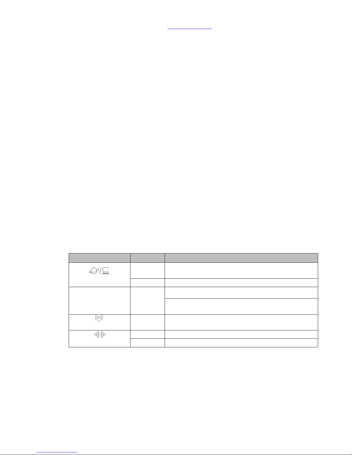
1. Hardware Instruction and Introduction
1.1 LED guide-light indicator
(1) 11AC Home Gateway(GR267c)
Guide-light
Light Color
Statue Instruction
Power
Green
Router Connected Properly
Wireless Status
Orange
2.4G Wi-Fi signal normal
Blue
5G Wi-Fi signal normal
WAN
Green
10/100Mbps Wireless network is connected properly
Orange
10/100/1000Mbps Wireless network is connected
properly
LAN
Green
Wireless network is connected properly
Orange
10/100/1000Mbps Wireless network is connected
properly
WPS Status
Green
Router Connected Properly
Green
Wi-Fi signal extending
Router Resetting
Sapido Technology Inc. www.sapido.com.tw
6
(2) Security Alarm(WDG71n)
Guide-light
Light Color
Statue Instruction
WAN/LAN
Orange
Power on is being applied on the device. After 30
seconds, the LED light will be green.
Green
Wireless network is connected properly
ZigBee
LED
Green
Steady:Security system working properly
Flashing: Alarm, Door & Window sensors and motion
detector are mapping the connection.
Wireless Status
Green
Wi-Fi signal normal
WPS Status
Orange
Wi-Fi signal extending
Green
Wi-Fi signal extended successfully

Sapido Technology Inc. www.sapido.com.tw
7
(3) Cloud Door & Window Sensor(DDLA0z)and Cloud Motion Sensor(MDKA0z)
Product
Guide-light
Light Color
Statue Instruction
DDLA0z
ZigBee
Red
Connecting with WDG71n
Green
Connected with WDG71n successfully
Orange
Low Battery
MDKA0z
ZigBee
Red
Connecting with WDG71n
Green
Connected with WDG71n successfully
Orange
Low Battery
Sapido Technology Inc. www.sapido.com.tw
8
(4) Smart Cloud Night Vision Camera with Audio Wireless Router(IPJC2n)
Guide-light
Light Color
Statue Instruction
Power
Green
IR Recording properly
WAN
Green
Wireless network is connected properly
LAN
Green
Wireless network is connected properly
Wireless Status
Green
Wi-Fi signal normal
WPS Status
Orange
Wi-Fi signal extending
Green
Wi-Fi signal extended successfully

Sapido Technology Inc. www.sapido.com.tw
9
(5) Smart Cloud Control Insight Switch Wireless Router(WSG70n)
Guide-light
Light Color
Statue Instruction
WAN/LAN
Orange
Power on is being applied on the device. After 30
seconds, the LED light will be green.
Green
Wireless network is connected properly
Manual Button
Green
Power ON
No Light
Power OFF
Wireless Status
Green
Wi-Fi signal normal
WPS Status
Orange
Wi-Fi signal extending
Green
Wi-Fi signal extended successfully

Sapido Technology Inc. www.sapido.com.tw
10
1.2 Hardware Instruction
(2) 11AC Home Gateway(GR267c)
Button and Port
Function Description
WAN
Connect to xDSL/Fiber, Static IP, Dynamic IP, PPTP, L2TP, Wi-Fi ISP AP,
WiFi-AP
LAN
* Connecting to on-line equipment, such as personal PC, web-cam,
printer server, etc.
* If more LAN ports are needed, please apply Switch/Hub for extension
Power ON/OFF
Power ON/OFF
USB
Connectable
Power
Transformer Connected (In-Package)
RESET
REBOOT
* Press over 10 seconds to factory default settings(like your Wi-Fi
password)
* Press about 3 seconds, the device will be rebooted

Sapido Technology Inc. www.sapido.com.tw
11
(2) Security Alarm(WDG71n)
Guide-light
Statue Instruction
WAN/LAN
Connect to xDSL/Fiber, Static IP, Dynamic IP, PPTP, L2TP, Wi-Fi ISP AP,
WiFi-AP
Power Outlet
Power supply 100V-240V
ZigBee/ Alarm
power Off Button
For ZigBee signal extend, it is also a button for turn on/off alarm
manually
Network Mode
Switch
Please switch to the R mode while the RJ45 cable is connecting to the
xDSL modem and WDG71n
Please switch to A mode while RJ45 cable is connecting to Sapido router
and WDG71n.
Please switch to the W mode while connecting to Wi-Fi network by
Sapido router.
Please switch to the R mode while connecting to the network by
other brand routers.
Reset Button
Press over 10 seconds to factory default settings(like your Wi-Fi
password)
Press about 3 seconds, the device will be rebooted

Sapido Technology Inc. www.sapido.com.tw
12
(3) Cloud Motion Sensor(MDKA0z)and Cloud Door & Window Sensor(DDLA0z)
Product
Button
Statue Instruction
DDLA0z
Power Button
ON:Power On
OFF:Power Off
ZigBee LED
ZigBee signal connecting
MDKA0z
Power Button
ON:Power On
OFF:Power Off
ZigBee LED
ZigBee signal connecting

Sapido Technology Inc. www.sapido.com.tw
13
(4) Smart Cloud Night Vision Camera with Audio Wireless Router(IPJC2n)
Button and Port
Function Description
WAN
Connect to xDSL/Fiber, Static IP, Dynamic IP, PPTP, L2TP, Wi-Fi ISP AP,
WiFi-AP
LAN
* Connecting to on-line equipment, such as personal PC, web-cam,
printer server, etc.
* If more LAN ports are needed, please apply Switch/Hub for extension
USB
Connectable
Micro USD Power
Port
Please connect with Sapido adapter.
Volume (- +)
Adjust the volume of speaker
R/A/W Mode
* Switch to R mode: connects between xDSL modem and IPJC2n.
* Switch to A mode: Connects between Sapido router and IPJC2n.
* Switch to W mode: Build WiFi bridge connection to Sapido router.
* Connecting with other brand router via Ethernet cord, please switch
to R mode.
RESET
REBOOT
* Press over 10 seconds to factory default settings(like your Wi-Fi
password)
* Press about 3 seconds, the device will be rebooted

Sapido Technology Inc. www.sapido.com.tw
14
(5) Smart Cloud Control Insight Switch Wireless Router(WSG70n)
Guide-light
Statue Instruction
WAN/LAN
Connect to xDSL/Fiber, Static IP, Dynamic IP, PPTP, L2TP, Wi-Fi ISP AP,
WiFi-AP
Power Outlet
Power supply 100V-240V
Manual Button
Switch power ON/OFF
Network Mode
Switch
Please switch to the R mode while the RJ45 cable is connecting to the
xDSL modem and WSG70n
Please switch to A mode while RJ45 cable is connecting to Sapido
router and WSG70n.
Please switch to the W mode while connecting to Wi-Fi network by
Sapido router.
Please switch to the R mode while connecting to the network by
other brand routers.
RESET
REBOOT
* Press over 10 seconds to factory default settings(like your Wi-Fi
password)
* Press about 3 seconds, the device will be rebooted
Sapido Technology Inc. www.sapido.com.tw
15
1.3 Hardware Installation
1.3.1 Wi-Fi Application Instruction
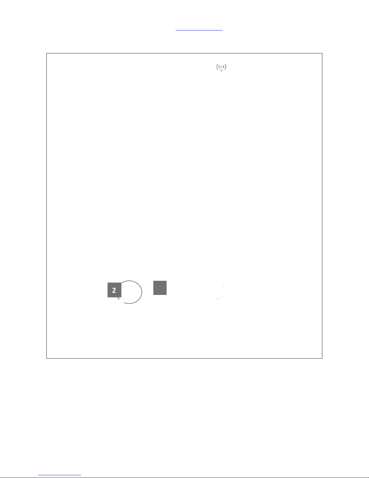
Step 1. Plug in first [2], install both Antenna on Home Gateway (GR267c) [1], and press the
white button [3] to start up. Wait for 30 seconds and both ( )/ ( ) turn on means start
up successfully.
11ac Home Gateway(GR267c) is the main router of your SH106+, which with two
different Antennas (one is supported 7dbi, the other one is supported 5dbi) to remain
the quality of WiFi transmission function. The SH106+, which is combined Security Kit
(CS101x), IP Cam (IPJC2n), and Smart Switch (WSG70n), as a package.
2
3

Sapido Technology Inc. www.sapido.com.tw
16
Step 2. Please switch to W mode on the lateral side of Alarm (WDG71n), then plug on the
power outlet. WDG71n is starting up when the WAN/LAN indicator turning red. The system is
completely turn on when ZigBee light and all LED lights turn green after 30 seconds. The alarm
(WDG71n) can not only deter the intruders by alert sound, but also warn the owner about any
unusual circumstances are happening. For example, the door and window to which are
attached Cloud Door & Window Sensors were opened by intruders, or the Cloud Motion Sensor
detected intruders.
Step 3.Please open the lid of the Cloud Door & Window Sensor (DDLA0z), and insert 2 x AAA
batteries.

Sapido Technology Inc. www.sapido.com.tw
17
Step 4. Please tear the double-sided tape and
paste on the back of Cloud Door & Window
Sensor (DDLA0z). Then paste the DDLA0z one
part on the frame of Window, and the other
part on the Window. The interval of both
parts is no longer than 1 cm. (You can also
fasten the DDLA0z by the attached fasteners.)
Step 5.Please turn on the power. When the
ZigBee light is blinking, which means the
DDLA0z is mapping with alarm (WDG71n).
Once the Window is opened, the alarm will
start to have the alert sound.
Step 6.Please open the lid of the Cloud Motion Sensor (MDKA0z) and insert 2 x AAA batteries.
Before close the lid, switch the power to ON.
Step 7.When the left light
(ZigBee) of MDKA0z is
blinking, means the MDKA0z
is connecting properly with
WDG71n.
Step 8.After fastening the MDKA0z on the hallway or gate, it
will trigger the alarm (WDG71n) if someone approaches the
MDKA0z.

Sapido Technology Inc. www.sapido.com.tw
18
Step 9. Open the window, which has installed with Window & Door Sensor (DDLA0z) to trigger
the Alarm (WDG71n). Please press the ZigBee button to turn off the alarm manually on Security
Alarm (WDG71n).

Sapido Technology Inc. www.sapido.com.tw
19
Step 10. Get started to make the WPS wireless (Wi-Fi) connection of Security Alarm (WDG71n) and
Home Gateway (GR267c): Please press the WPS button on both Security Alarm Router (WDG71n)
and Home Gateway (GR267c) separately. When both of the lights stop blinking, it means the
connection is completed.
Step 11. Make sure your IP Cam (IPJC2n) is on
W mode.
Step 12. Put your IP Cam (IPJC2n) at your
entrance or window to monitor anytime.
Power on, turns red and blink to boot.

Sapido Technology Inc. www.sapido.com.tw
20
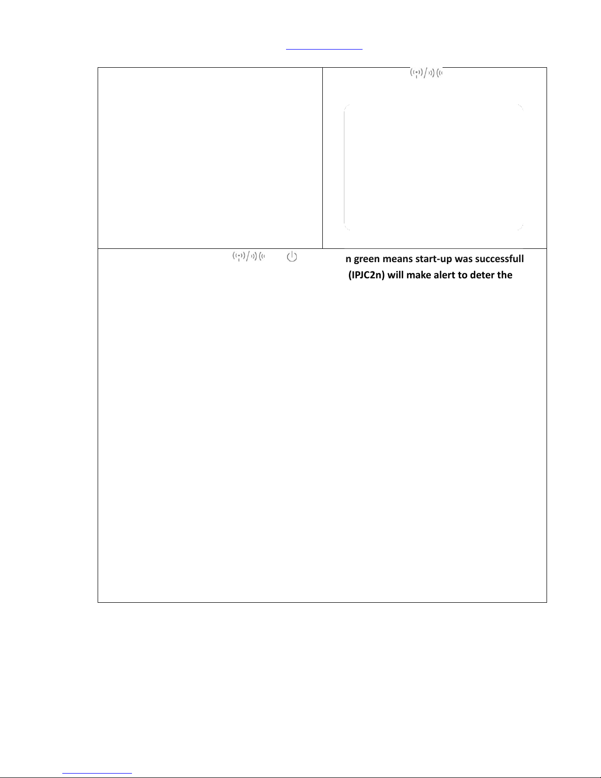
Step 13. Wait for 30 seconds, and all will turn green means start-up was successfully.
Once your windows or door are opened, your IP Cam (IPJC2n) will make alert to deter the
intruder.

Sapido Technology Inc. www.sapido.com.tw
21
Step 14. There are two ways to make WiFi connection with IP Cam (IPJC2n) based on distance:
(2) Get started to make the WPS wireless (Wi-Fi) connection of IP Cam (IPJC2n) and Home
Gateway (GR267c) if they are closer to each other: Please press the WPS button on both
IP Cam (IPJC2n) and Home Gateway (GR267c) separately. When both of the lights stop
blinking, it means the connection is completed.
(3) Get started to make the WPS wireless (Wi-Fi) connection of IP Cam (IPJC2n) and Security
Alarm (WDG71n) if they are closer: Please press the WPS button on both IP Cam (IPJC2n)
and Security Alarm (WDG71n) separately. When both of the lights stop blinking, it means
the connection and encryption are completed.
Step 15. Switch your Smart Switch to “W” network mode and Plug-in. Wait for 30 seconds to
start up. When Wireless/WPS light turns to green, which means the start-up was
successful.
3

Sapido Technology Inc. www.sapido.com.tw
22
Step 16. Plug in with the non-electronic control type of household appliances like below: One
Switch for one electric appliance only. No extension cord recommend in order to avoid heavy
electric tension.

Sapido Technology Inc. www.sapido.com.tw
23
Step 17. There are three ways to make WiFi connection with Smart Switch (WSG70n) based on
distance:
(1) Get started to make the WPS wireless (Wi-Fi) connection of Home Gateway(GR267c) and
Smart Switch (WSG70n) if they are closer: Please press the WPS button on both Home
Gateway (GR267c) and Smart Switch (WSG70n) separately. When both of the lights stop
blinking, it means the connection is completed.
(2) Get started to make the WPS wireless (Wi-Fi) connection of Security Alarm (WDG71n) and
Smart Switch (WSG70n) if they are closer: Please press the WPS button on both Security
Alarm Router (WDG71n) and WSG70n separately. When both of the lights stop blinking, it
means the connection is completed.
(3) Get started to make the WPS wireless (Wi-Fi) connection of IP Cam (IPJC2n) and Smart
Switch (WSG70n) if they are closer: Please press the WPS button on both Smart Switch
(WSG70n) and IPJC2n separately. When both of the lights stop blinking, it means the
connection is completed.
Press WPS botton
Sapido Technology Inc. www.sapido.com.tw
24
1.3.2 Wired & Wi-Fi Application Instruction
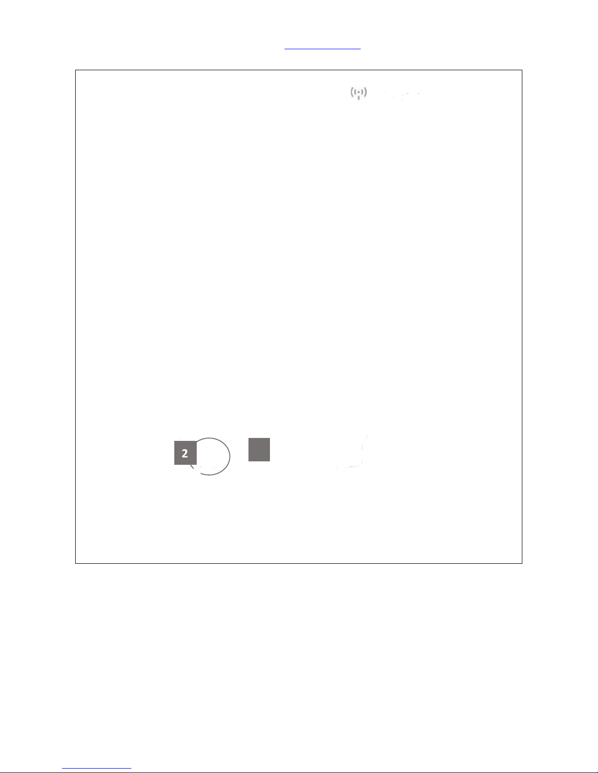
Step 1. Plug in first [2], install both Antenna on Home Gateway (GR267c) [1], and press the
white button [3] to start up. Wait for 30 seconds and both ( )/ ( ) turn on means start
up successfully.
11ac Home Gateway(GR267c) is the main router of your SH106+, which with two
different Antennas (one is supported 7dbi, the other one is supported 5dbi) to remain
the quality of WiFi transmission function. The SH106+, which is combined Security Kit
(CS101x), IP Cam (IPJC2n), and Smart Switch (WSG70n), as a package.
2
3
Sapido Technology Inc. www.sapido.com.tw
25
Step 2. Make sure your IP Cam (IPJC2n) is on A
mode.
Step 3. Power on, turns red and blink
to boot.
Step 4. Wait for 30 seconds, and all will turn green means start-up was successfully.
Once your windows or door are opened, your IP Cam (IPJC2n) will make alert to deter the
intruder.

Sapido Technology Inc. www.sapido.com.tw
26
Step 5. Get an Ethernet cable and connect to both Home Gateway LAN port and IPJC2n anyone
port. Shown the picture below:
Step 6.Please switch to W mode on the lateral side of Alarm (WDG71n), then plug on the power
outlet. WDG71n is starting up when the WAN/LAN indicator turning red. The system is
completely turn on when ZigBee light and all LED lights turn green after 30 seconds. The alarm
(WDG71n) can not only deter the intruders by alert sound, but also warn the owner about any
unusual circumstances are happening. For example, the door and window to which are
attached Cloud Door & Window Sensors were opened by intruders, or the Cloud Motion Sensor
detected intruders.
Home Gateway

Sapido Technology Inc. www.sapido.com.tw
27
Step 7.Please open the lid of the Cloud Door & Window Sensor (DDLA0z), and insert 2 x AAA
batteries.
Step 8. Please tear the double-sided tape and
paste on the back of Cloud Door & Window
Sensor (DDLA0z). Then paste the DDLA0z one
part on the frame of Window, and the other
part on the Window. The interval of both
parts is no longer than 1 cm. (You can also
fasten the DDLA0z by the attached fasteners.)
Step 9.Please turn on the power. When the
ZigBee light is blinking, which means the
DDLA0z is mapping with alarm (WDG71n).
Once the Window is opened, the alarm will
start to have the alert sound.
Step 10.Please open the lid of the Cloud Motion Sensor (MDKA0z) and insert 2 x AAA batteries.
Before close the lid, switch the power to ON.

Sapido Technology Inc. www.sapido.com.tw
28
Step 11.When the left light
(ZigBee) of MDKA0z is
blinking, means the MDKA0z
is connecting properly with
WDG71n.
Step 12.After fastening the MDKA0z on the hallway or gate, it
will trigger the alarm (WDG71n) if someone approaches the
MDKA0z.
Step 13. Open the window, which has installed with Window & Door Sensor (DDLA0z) to trigger
the Alarm (WDG71n). Please press the ZigBee button to turn off the alarm manually on Security
Alarm (WDG71n).

Sapido Technology Inc. www.sapido.com.tw
29
Step 14. Get started to make the WPS wireless (Wi-Fi) connection of Security Alarm (WDG71n) and
Home Gateway (GR267c): Please press the WPS button on both Security Alarm Router (WDG71n)
and Home Gateway (GR267c) separately. When both of the lights stop blinking, it means the
connection is completed.
Step 15. Switch your Smart Switch to “W” network mode and Plug-in. Wait for 30 seconds to
start up. When Wireless/WPS light turns to green, which means the start-up was
successful.
3

Sapido Technology Inc. www.sapido.com.tw
30
Step 16. Plug in with the non-electronic control type of household appliances like below: One
Switch for one electric appliance only. No extension cord recommend in order to avoid heavy
electric tension.

Sapido Technology Inc. www.sapido.com.tw
31
Step 17. There are three ways to make WiFi connection with Smart Switch (WSG70n) based on
distance:
(4) Get started to make the WPS wireless (Wi-Fi) connection of Home Gateway(GR267c) and
Smart Switch (WSG70n) if they are closer: Please press the WPS button on both Home
Gateway (GR267c) and Smart Switch (WSG70n) separately. When both of the lights stop
blinking, it means the connection is completed.
(5) Get started to make the WPS wireless (Wi-Fi) connection of Security Alarm (WDG71n) and
Smart Switch (WSG70n) if they are closer: Please press the WPS button on both Security
Alarm (WDG71n) and WSG70n separately. When both of the lights stop blinking, it means
the connection is completed.
(6) Get started to make the WPS wireless (Wi-Fi) connection of IP Cam (IPJC2n) and Smart
Switch (WSG70n) if they are closer: Please press the WPS button on both Smart Switch
(WSG70n) and IPJC2n separately. When both of the lights stop blinking, it means the
connection is completed.
Press WPS botton

Sapido Technology Inc. www.sapido.com.tw
32
2. APP Download and Network Setup (iOS system)
2.1 Wi-Fi Connection Way for APP Installation
Step 1. Please go to APP Store
to download Sapido APP.
Step 2. Please click and search by the key word <Sapido>.
Click <Free> → <Install>.
Step 3. After installing Sapido
APP, it will create a shortcut
automatically on the main
page of your iPhone.
Step 4. Please open the
<Settings> function on your
iPhone.
Step 5. Please turn on and
search for WiFi network from
the Main Router (GR267c).

Sapido Technology Inc. www.sapido.com.tw
33
Step 6. Select (GR267c) WiFi
signal to connect.
Step 7. Activate Sapido APP.
Step 8. Click “New IOT”.
Step 9. Sapido APP will show the network device name and user name. All you have to do is to give
a name for the network domain in blank and enter the default password “admin” in blank.
In order to protect your network domain security, please click <Change Password> and
enter the new password. Then, click <New IOT> to finish the process. Now you have to
enter your new password to access the domain security
IOT name
You can give your IOT Name in the
blank.
Device
Name
The Device name will show up
automatically, doesn't need to change.
User name
of Domain
The account will show up
automatically, doesn't need to change
Password of
Domain
Need to enter the default password
“admin”
The Options
of Changing
Password
You can change the password for your
domain

Sapido Technology Inc. www.sapido.com.tw
34
Step 10. Connecting…
Step 11. Click <IOT Settings>
Step 12. Entered the IOT
Settings, you can see the
security system is built-up (as
below).
: Home Gateway
: Door & Window Sensor
: Motion Sensor
: Security Alarm, IP Cam,
and Smart Switch
: Battery Status

Sapido Technology Inc. www.sapido.com.tw
35
Step 13. In IOT Setting page,
you can rename the device.
Select Home Gateway (GR267c)
and click “Rename”
Step 14. After typing in the
new name, click “Apply” to
confirm.
Step 15. Home Gateway
(GR267c) has been shown with
new device name.
Step 16. In IOT Setting page,
you can rename the device.
Select IP Camera (IPJC2n) and
click “Rename”
Step 17. After typing in the
new name, click “Apply” to
confirm.
Step 18. IP Camera has been
shown with new device name.

Sapido Technology Inc. www.sapido.com.tw
36
Step 19. Please select the
Security Alarm router
(WDG71n) first, then click
<Rename>
Step 20. After entering the new
name, please click <Apply>,
then it will show the new
name.
Step 21. The alarm (WDG71n)
had been changed to the new
name.
Step 22. To rename the Cloud
Door & Window Sensor:
Choose the Cloud Motion
Sensor (MDKA0z_xxx) in IOT
Setting first, then click
<Rename>.
Step 23. After entering the new
name, please click <Apply>,
then it will show the new
name.
Step 24. The Cloud Motion
Sensor (MDKA0z_xxx) had
been changed to the new
name.
Home Gateway
Home Gateway
Home Gateway

Sapido Technology Inc. www.sapido.com.tw
37
Step 25. To rename the Cloud
Motion Sensor: Choose the
Cloud Door & Window Sensor
(DDLA0z_xxx) in IOT Setting
first, then click <Rename>
Step 26. After entering the new
name, please click <Apply>,
then it will show the new
name
Step 27. The Cloud Door &
Window Sensor (DDLA0z_xxx)
had been changed to the new
name.
Home Gateway
Home Gateway
Home Gateway
Home Gateway
Home Gateway
Home Gateway

Sapido Technology Inc. www.sapido.com.tw
38
Step 28. To rename the Smart
Switch: Choose the Smart
Switch (WSG70n_xxx) in IOT
Setting first, then click
<Rename>
Step 29. After entering the new
name, please click <Apply>,
then it will show the new
name
Step 30. The Smart Switch
(WSG70n_xxx) had been
changed to the new name.
Step 31. After renaming, click to control the remote PC and click to access GUI.

Sapido Technology Inc. www.sapido.com.tw
39
Step 32. Please turn on WiFi to connect the Home Gateway (GR267c) to control the security
system.
Security
System
Arm
Once you are sleeping or go out, please set
the shield as green, which represents the
security system is working.
Alarm
Triggere
d
When the security system was triggered,
the shield will turn red. Click the shield
from red to green to turn off the alert
sound and stay security mode.
Security
System
Disarm
To click the shield to turn gray represents
turn off the security system.

Sapido Technology Inc. www.sapido.com.tw
40
2.2 Both Wi-Fi & Wired Connection for APP Installation
Step 1. Please go to APP Store
to download Sapido APP.
Step 2. Please click and search by the key word <Sapido>.
Click <Free> → <Install>.
Step 3. After installing Sapido
APP, it will create a shortcut
automatically on the main
page of your iPhone.
Step 4. Please open the
<Settings> function on your
iPhone.
Step 5. Please turn on and
search for WiFi network from
the Home Gateway (GR267c).

Sapido Technology Inc. www.sapido.com.tw
41
Step 6. Select (GR267c) WiFi
signal to connect.
Step 7. Activate Sapido APP.
Step 8. Click “New IOT”.
Step 9. Sapido APP will show the network device name and user name. All you have to do is to give
a name for the network domain in blank and enter the default password “admin” in blank.
In order to protect your network domain security, please click <Change Password> and
enter the new password. Then, click <New IOT> to finish the process. Now you have to
enter your new password to access the domain security
IOT name
You can give your IOT Name in the
blank.
Device
Name
The Device name will show up
automatically, doesn't need to change.
User name
of Domain
The account will show up
automatically, doesn't need to change
Password of
Domain
Need to enter the default password
“admin”
The Options
of Changing
Password
You can change the password for your
domain

Sapido Technology Inc. www.sapido.com.tw
42
Step 10. Connecting…
Step 11. Click <IOT Settings>
Step 12. Entered the IOT
Settings, you can see the
security system is built-up (as
below).
: Home Gateway
: Door & Window Sensor
: Motion Sensor
: Security Alarm, IP Cam,
and Smart Switch
: Battery Status

Sapido Technology Inc. www.sapido.com.tw
43
Step 13. In IOT Setting page,
you can rename the device.
Select Home Gateway (GR267c)
and click “Rename”
Step 14. After typing in the
new name, click “Apply” to
confirm.
Step 15. Home Gateway
(GR267c) has been shown with
new device name.
Step 16. In IOT Setting page,
you can rename the device.
Select IP Camera (IPJC2n) and
click “Rename”
Step 17. After typing in the
new name, click “Apply” to
confirm.
Step 18. IP Camera has been
shown with new device name.
And please click the “GUI” in
the right top.

Sapido Technology Inc. www.sapido.com.tw
44
Step 19. You will see IOT Network of the IP Cam. Please select the
type of encryption to “WPA2”, and enter the new password (at
least 8 characters/numbers), click <Apply>. (You can arrange the
screen for easier watching manually)
Step20. Please wait for the
setup operation.
Step 21. After setting, click
“Back” to the front page.
Step 22. Please select the
Security Alarm router
(WDG71n) first, then click
<Rename>
Step 23. After entering the new
name, please click <Apply>,
then it will show the new
name.
Home Gateway
Home Gateway
Home Gateway

Sapido Technology Inc. www.sapido.com.tw
45
Step 24. The alarm (WDG71n)
had been changed to the new
name.
Step 25. To rename the Cloud
Door & Window Sensor:
Choose the Cloud Motion
Sensor (MDKA0z_xxx) in IOT
Setting first, then click
<Rename>.
Step 26. After entering the new
name, please click <Apply>,
then it will show the new
name.
Step 27. The Cloud Motion
Sensor (MDKA0z_xxx) had
been changed to the new
name.
Step 28. To rename the Cloud
Motion Sensor: Choose the
Cloud Door & Window Sensor
(DDLA0z_xxx) in IOT Setting
first, then click <Rename>
Step 29. After entering the new
name, please click <Apply>,
then it will show the new
name
Home Gateway
Home Gateway
Home Gateway
Home Gateway
Home Gateway
Home Gateway
Home Gateway

Sapido Technology Inc. www.sapido.com.tw
46
Step 30. The Cloud Door &
Window Sensor (DDLA0z_xxx)
had been changed to the new
name.
Step 31. To rename the Smart
Switch: Choose the Smart
Switch (WSG70n_xxx) in IOT
Setting first, then click
<Rename>
Step 32. After entering the new
name, please click <Apply>,
then it will show the new
name
Step 33. The Smart Switch
(WSG70n_xxx) had been
changed to the new name.
Step 34. After renaming, click to control the remote PC and
click to access GUI.
Entrance
Home Gateway

Sapido Technology Inc. www.sapido.com.tw
47
Step 35. Please turn on WiFi to connect the Home Gateway (GR267c) to control the security
system.
Security
System
Arm
Once you are sleeping or go out, please set
the shield as green, which represents the
security system is working.
Alarm
Triggere
d
When the security system was triggered,
the shield will turn red. Click the shield
from red to green to turn off the alert
sound and stay security mode.
Security
System
Disarm
To click the shield to turn gray represents
turn off the security system.

Sapido Technology Inc. www.sapido.com.tw
48
3. Internet Settings
Make sure the network environment stable for any of your smartphone and handheld devices using
first, this step will let you receive push notification successfully while you go out. Follow the security
system set-up steps as below:
Step 1. Connect the Ethernet cable to GR267c WAN port.

Sapido Technology Inc. www.sapido.com.tw
49
Step 2. Log in APP and click
“Internet Settings”, and then
your internet network will be
automatically detected
Step 3. Please enter your ISP
account and password, and
select WPA2 as the encryption
mode (at lease 8 (included)
digital characters), and finally
click “Apply”.
(Please memorize your Wi-Fi
security password)
Step 4. Please wait for the
setup operation. Do not turn
off or return.
Step 5. After setting up, it will
pop up on the main page of
domain. You can access the
domain if you are under the 3G
network services. Meanwhile,
you are confirmed the remote
connection actively.
Step 6. If your smart phone
didn't have 3G network
services, please turn on Wi-Fi of
your smartphone and choose
the network from GR261c. Enter
the password that setup by step
3, then your smart phone has
been connected to the main
router (GR267c).
Step 7. Back to the Sapido APP
again, you will see the new
name of domain that you just
setup.

Sapido Technology Inc. www.sapido.com.tw
50
Step 8. The instruction of the symbols from the main page:
Guide-light
Light
Statue Instruction
1. The lights of
device of the
domain
Green- Domain and network is
connected.
Gray- Domain and network is
disconnected
Red- Event alert
2. The light
symbols of the
Cloud Security
Green- Security System Arm.
Gray- Security System Disarm.
Red- Alarm is triggered.
(Empty)-No Installed or Security
System offline.
3. Change the
password Key
To change the password of domain.
4. Trash Can
Symbol
To delete the domain.
Congratulations!!! The Internet Setting of Home Gateway (GR267c) is completed. Please enter the Smart
Home System to utilize the functions.

Sapido Technology Inc. www.sapido.com.tw
51
4. Security System Application
Once someone opened the door and windows when you're not home, or the Cloud Motion Sensor
detects any unusual situation, your smartphone will receive a push notification, the alarm at home
will make sound at the same time as well. In addition, you can control the situation by self via
Sapido APP. Click the push notification to enter the APP main page, you will see the shield is red ,
and the event alert will show up in front of the network name. Meanwhile, you can enter the
Message to obtain the detail of event (Ex: 2nd Floor Window is opened), and turn off the alert .
Moreover, with 30 seconds real-time recording and monitor the environment via IP Camera. Press
“Arm ” and “Voice Sender ” to deter the intruder. When everything settle down, turn off the
alarm and the security system is still working. The shield on the main page will stay green .
※ Press ZigBee button to directly turn off the alarm if you are at home.

Sapido Technology Inc. www.sapido.com.tw
52
4.1 Door & Window Sensor (DDLA0z)
Door & Window Sensor has preinstalled the setting of “push notification” and “alert” already.
Once it detects abnormal situation, the alarm system will be activated.
Default of Door & Window Sensor
Step 1. Click <Security>
Step 2. Click <Door & Window
Sensor>.
Step 3. Select your specific Door
& Window Sensor.
Step 4. You can see the “Notification Message”, “Sensor Alerm”, “Speaker”, and “Video Record” are
selected already, means that WDG71n will send you a push notification and make alert at the same
time.

Sapido Technology Inc. www.sapido.com.tw
53
Step 5. If you want your lights
on while window is opened,
just select the Switch. (shown
in red frame)
Step 6. Select “Switch Mode”
Step 7. To face your needed,
you can choose ON, OFF, or
Repeat mode of your Switch.
Step 8. After click “Switch”, you will receive push notification and alarm will triggered when
window is opened. Also, 30 seconds recording and Switch will turn on at the same time.

Sapido Technology Inc. www.sapido.com.tw
54
There are two ways to turn off the alarm through Sapido APP when the Door & Windows
Sensor (DDLA0z) is triggered. Follow the steps as below.
The 1st method to turn off the alarm
Step 1. You will receive the
push notification as the photo
below. Please click the push
notification and enter the
security system in APP.
Step 2. You will see the event
alert , and the shield will turn
red . To mute the alarm, just
click the shield to return to
green.
Step 3. Click <Message> to
understand the situation
immediately. It will show the
event list included the event
date and time. To understand
more about event's detail,
please select the “event”.

Sapido Technology Inc. www.sapido.com.tw
55
Step 4. Click “Camera” to view
the situation of event right
away.
Step 5. Click “ Arm” once you find the intruder in the
smartphone screen. : Volume adjustor.
Step 6. Also, you can click “ Voice Sender” once you find the intruder. And then you can click
“Back” to main menu.

Sapido Technology Inc. www.sapido.com.tw
56
The 2nd method to turn off the alarm
Step 1. You will see the event
alert , and the shield will turn
red .
Step 2. The event list is sorted by
date and time. You can turn off
the alert when you re-enter the
“event” again to view the page
with more detail.
Step 3. Click the silence sign
to mute the alarm and click
Record Video to view the 30
seconds recording. Then back to
the main list and enter
“Camera” to view the real-time
monitor.
Step 4. Click “Camera” to view
the situation of event right
away.
Step 5. Click “ Arm” once you find the intruder in the
smartphone screen. : Volume adjustor.

Sapido Technology Inc. www.sapido.com.tw
57
Step 6. Also, you can click “ Voice Sender” once you find the intruder. And then you can click
“Back” to main menu.
Step 7. Click “Back “again to main list. You will see the shield back to green . Also, the event alert
will turn to the green dote , which means that the alert is turn off but the security system keep
working.

Sapido Technology Inc. www.sapido.com.tw
58
4.2 Cloud Motion Sensor (MDKA0z)
Cloud Motion Sensor (MDKA0z) has preinstalled the setting of “push notification” and “alert”
already. Once it detects abnormal situation, the alarm system will be activated.
Default of Cloud Motion Sensor (MDKA0z)
Step 1. Click <Security>
Step 2. Click <Motion Sensor>
Step 3. Select your specific Cloud
Motion Sensor
Step 4. You can see the “Notification Message”, “Sensor Alerm”, “Speaker”, and “Video Record” are
selected already, means when someone pass the 2nd floor entrance(MDKA0z), it will send you a push
notification and make alert at the same time.

Sapido Technology Inc. www.sapido.com.tw
59
Step 5. If you want your lights
on while someone pass the 2nd
floor entrance(MDKA0z), just
select the Switch. (shown in
red frame)
Step 6. Select “Switch Mode”
Step 7. To face your needed,
you can choose ON, OFF, or
Repeat mode of your Switch.
Step 8. After click “Switch”, you will receive push notification and alarm will triggered when
someone pass 2nd floor entrance(MDKA0z) . Also, 30 seconds recording and Switch will turn on at
the same time.

Sapido Technology Inc. www.sapido.com.tw
60
There are two ways to turn off the alarm through Sapido APP when the Cloud Motion Sensor
(MDKA0z) is triggered. Follow the steps as below.
The 1st method to turn off the alarm
Step 1. You will receive the
push notification as the photo
below. Please click the push
notification and enter the
security system in APP.
Step 2. You will see the event
alert , and the shield will turn
red . To mute the alarm, just
click the shield to return to
green.
Step 3. Click <Message> to
understand the situation
immediately. It will show the
event list included the event
date and time. To understand
more about event's detail,
please select the “event”.

Sapido Technology Inc. www.sapido.com.tw
61
Step 4. Click “Camera” to view
the situation of event right
away.
Step 5. Click “ Arm” once you find the intruder in the
smartphone screen. : Volume adjustor.
Step 6. Also, you can click “ Voice Sender” once you find the intruder. And then you can click
“Back” to main menu.

Sapido Technology Inc. www.sapido.com.tw
62
The 2nd method to turn off the alarm
Step 1. Open the Sapido APP,
you can enter <Message> to
view the situation immediately.
Step 2. The event list is sorted by
date and time. You can turn off
the alert when you re-enter the
“event” again to view the page
with more detail.
Step 3. Click the silence sign
to mute the alarm and click
Record Video to view the 30
seconds recording. Then back to
the main list and enter
“Camera” to view the real-time
monitor.

Sapido Technology Inc. www.sapido.com.tw
63
Step 4. Click “Camera” to view
the situation of event right
away.
Step 5. Click “ Arm” once you find the intruder in the
smartphone screen. : Volume adjustor.
Step 6. Also, you can click “ Voice Sender” once you find the intruder. And then you can click
“Back” to main menu.

Sapido Technology Inc. www.sapido.com.tw
64
Step 7. Click “Back “again to main list. You will see the shield back to green . Also, the event alert
will turn to the green dote , which means that the alert is turn off but the security system keep
working.

Sapido Technology Inc. www.sapido.com.tw
65
5. Instruction of Security Alarm Router (WDG71n)
WDG71n is not only an alarm but also a sensor that can detects intensity of the environmental
factors such as sound, temperature, and light. It is suggested to place the alarm sensor in an area
with an open space. For example, kitchen and living room.
The sensor will alarm if it detects an abnormal movement in the level of sound, temperature, and
light at home. At the same time, the Security Alarm Router WDG71n will send you an alert message
to tell you the emergency immediately. In addition, you can control the situation by self via Sapido
APP. Click the push notification to enter the APP main page, you will see the shield is red , and the
event alert will show up in front of the network name. Meanwhile, you can enter the Cloud
Message to obtain the detail of event (Ex: Unusual temperature in kitchen), and turn off the alert
at the same time.
※ If you are at home, you can press the ZigBee button on the alarm (WDG71n) to turn off the alarm.

Sapido Technology Inc. www.sapido.com.tw
66
5.1 Sound Sensor
Step 1. You can adjust the
alarm sound level based on
the level of Decibels (dB) in
<Sensor> section.
Step 2. Click <Sound Sensor>
Step 3. Current alarm
detected volume (dB) level
will show on the right of the
Sound Sensor page.
Step 4. Please click <Warning
Device>
Step 5. When it detects the
abnormal sound in the space,
you will receive an alert
message on your phone.
Meanwhile, the alarm system
will activate. Please choose
<Notification Message> and
<Sensor Alarm>
Step 6. For setting up the
condition of the alarm trigger,
please click Sensor Alarm
Device (shown below in red
frame).

Sapido Technology Inc. www.sapido.com.tw
67
Step 7. There are two different scenarios are provided from the function of "dB" section. You
can adjust the sound level between 0dB ~ 110dB. (Increments 5dB a time)
Step 8. The preinstall alarm setting is “continuity alarm”, means that the alarm will touch off
when the intensity reaches the level of indoor maximum limit. Sirens will continue beeping until
you turn off the alarm manually. If you want to change the setting to Define Alarm Sounds, then
you can adjust alarm sounding time under any abnormal movement, such as: 1 second, 2
seconds, 5 minutes ... etc.

Sapido Technology Inc. www.sapido.com.tw
68
Step 9. There are 5 types of different selectable beep length of "Siren”. When settle down alarm
sounds and siren, please press "Done" at the top right of the page to return to the sensing
feature page.
Step 10. If you want your
lights on while window is
opened, just select the
Switch. (shown in red frame)
Step 11. Face your needed to
setup dB, for example, higher
than 60dB to make the
Switch triggered.
Step 12. To face your needed,
you can choose ON, OFF, or
Repeat mode of your Switch.

Sapido Technology Inc. www.sapido.com.tw
69
There is a way to mute the alarm through Sapido APP when the alarm (WDG71n) triggers
alarm.
Step 1. Open the Sapido APP,
you can enter <Message> to
view the situation
immediately.
Step 2. The event list is sorted
by date and time. If you enter
the “event” to view the details
while the shield is red. Please
select the “event” again to
view the page with more
detail.
Step 3. Click the silence sign
to mute the alarm and click
Record Video to view the 30
seconds recording. Then back
to the main list and enter
“Camera” to view the realtime monitor.
Step 4. Click “Camera” to
view the situation of event
right away.
Step 5. Also, you can click “ Voice Sender” to talk to your
child once you find out your child is crying. : Volume
adjustor.

Sapido Technology Inc. www.sapido.com.tw
70
5.2 Temperature Sensor
Step1. Click <Sensor>, you
can set up your
predetermined temperature
level to activate the alarm
system.
Step2. Click <Temperature
Sensor>
Step3. The page of
Temperature Sensor will
show the current in room
temperature. The preinstall
measurement setting is
“Celsius”.
Step 4. Click the <Sensor
Device>
Step5. Select the
“Notification Message” and
“Sensor Alarm” options, you
will receive a push
notification on your phone
and the alarm will make
beeping sound when the
temperature is in an
abnormal situation.
Step 6. For setting up the
condition of the alarm trigger
by the limit of trigger
temperature, please click
Sirens Device (shown below in
red frame).

Sapido Technology Inc. www.sapido.com.tw
71
Step 7. There are two different scenarios are provided from the function of "Celsius" section. You
can adjust the temperature level between 0 ° C ~ 50 ° C. (increments 1° C a time)

Sapido Technology Inc. www.sapido.com.tw
72
Step 8. The preinstall setting of "Sensor Alarm" is “Continuity Alarm”, means that the alarm will
touch off when the intensity reaches the level of indoor maximum limit. Sirens will continue
beeping until you turn off the alarm manually. If you want to change the setting to Define Alarm
Sounds, then you can adjust alarm sounding time under any abnormal movement, such as: 1
second, 2 seconds, 5 minutes ... etc.
Step 9. There are 5 types of different selectable beep length of "Siren”. When settle down alarm
sounds and siren, please press "Done" at the top right of the page to return to the sensing
feature page.

Sapido Technology Inc. www.sapido.com.tw
73
Step 10. If you want your
lights on while window is
opened, just select the
Switch. (shown in red frame)
Step 11. Face your needed to
setup Celsius, for example,
higher than 60C to make the
Switch triggered.
Step 12. To face your needed,
you can choose ON, OFF, or
Repeat mode of your Switch.

Sapido Technology Inc. www.sapido.com.tw
74
There is a way to mute the alarm through Sapido APP when the alarm (WDG71n) triggers
alarm.
Step 1. Open the Sapido APP,
you can enter <Message> to
view the situation
immediately.
Step 2. The event list is sorted
by date and time. If you enter
the “event” to view the details
while the shield is red. Please
select the “event” again to
view the page with more
detail.
Step 3. Click the silence sign
to mute the alarm and click
Record Video to view the 30
seconds recording. Then back
to the main list and enter
“Camera” to view the realtime monitor.
Step 4. Click “Camera” to
view the situation of event
right away.
Step 5. Also, you can click “ Voice Sender” to talk to your
family members once you find out your home is on fire.
: Volume adjustor.

Sapido Technology Inc. www.sapido.com.tw
75
5.3 Light Sensor
Step1. Click <Sensor>
Step2. Click <Light Sensor>
Step3. The page of Light
Sensor will show the current
in room brightness.
Step4. Click the <Siren
Device>
Step5. Select the
“Notification Message” and
“Sensor Alarm” options, you
will receive a push
notification on your phone
and the alarm will make
beeping sound when the
temperature is in an
abnormal situation.
Step 6. For setting up the
condition of the alarm trigger,
please click Sirens Device
(shown below in red frame).

Sapido Technology Inc. www.sapido.com.tw
76
Step 7. There are two different scenarios are provided from high to low for the brightness. You
can adjust the brightness level between 0Lm ~ 2000Lm.

Sapido Technology Inc. www.sapido.com.tw
77
Step 8. The preinstall setting of "Sensor Alarm" is continuity sounds, means that the alarm will
touch off when the intensity reaches the level of indoor maximum limit. Sirens will continue
beeping until you turn off the alarm manually. If you want to change the setting to Define Alarm
Sounds, then you can adjust alarm sounding time under any abnormal movement, such as: 1
second, 2 seconds, 5 minutes ... etc.
Step 9. There are 5 types of different selectable beep length of "Siren”. When settle down alarm
sounds and siren, please press "Done" at the top right of the page to return to the sensing
feature page.

Sapido Technology Inc. www.sapido.com.tw
78
Step 10. If you want your
lights on while window is
opened, just select the
Switch. (shown in red frame)
Step 11. Face your needed to
setup Celsius, for example,
higher than 400 Lm to make
the Switch triggered.
Step 12. To face your needed,
you can choose ON, OFF, or
Repeat mode of your Switch.

Sapido Technology Inc. www.sapido.com.tw
79
There is a way to mute the alarm through Sapido APP when the alarm (WDG71n) triggers
alarm.
Step 1. Open the Sapido APP,
you can enter <Message> to
view the situation
immediately.
Step 2. The event list is sorted
by date and time. If you enter
the “event” to view the details
while the shield is red. Please
select the “event” again to
view the page with more
detail.
Step 3. Click the silence sign
to mute the alarm and click
Record Video to view the 30
seconds recording. Then back
to the main list and enter
“Camera” to view the realtime monitor.
Step 4. Click “Camera” to
view the situation of event
right away.
Step 5. Click “ Arm” once you find the intruder in the
smartphone screen. : Volume adjustor.

Sapido Technology Inc. www.sapido.com.tw
80
Step 6. Also, you can click “ Voice Sender” to yield to intruder. : Volume adjustor.

Sapido Technology Inc. www.sapido.com.tw
81
6. Application of IP Camera
6.1. Surveillance Recording and Browse
6.1.1. Real-Time Recording
Step 1. Select “Camera”.
Step 2. Click the functional
key「 Record」
Step 3. Setting, please wait...
Step 4. When the recording
starts, you can find the red
pot on the top left corner.
Step 5. Video will be
automatically stored in the
USB drive of IP camera;
please go「 View
Videos」for video browse.
Step 6. Videos will be sorted
by date and time, please
directly choose the video you
want to view.

Sapido Technology Inc. www.sapido.com.tw
82
Step 7. Select the video for
immediate play.
Step 8. Click “Exit” when
finished, and goes back to
the last page. (Rotating the
device to enlarge for browse)
Step 9. Click “Download” if
you want to back up the files
to your smartphone or other
devices.
Step 10. Video
Downloading…
Step 11. Once download
successfully and then you can
play it.
Step 12. Downloaded files
will be directly stored in
“Camera” of “Download
List”.

Sapido Technology Inc. www.sapido.com.tw
83
Step 13. Please Click “
Stop” to stop recording.
Step 14. Click “Apply” and
await.
Step 15. Once the red pot is
disappeared, the recording
has been stopped.

Sapido Technology Inc. www.sapido.com.tw
84
6.1.2. Personalized Recording Schedule
You can set up the recording schedule at different time based on your requirement, such as
personalize the recording time during day time or bedtime, the operating method are as
below:
Step 1. Select “ Camera”
Step 2. Click “ Schedule” in
below.
Step 3. Click “New” to add
new schedule
Step 4. Cross day recording schedule of every 10pm to 6am of the next day. Set up 1st
recording schedule: please first select “Record Schedule”, and set up the start time at 22:00
and end time at 23:59, choose “Everyday” for Day, and finally click “Done” for confirmation.

Sapido Technology Inc. www.sapido.com.tw
85
Step 5. Please await.... do not
shut down the APP
Step 6. After completing the
schedule added, the screen
will automatically go back to
home page. Please click the
network to log in.
Step 7. Click “Camera”
Step 8. Click “ Schedule” in
below
Step 9. You can find the schedule you just added. Please
again click “New” if you want to add new schedule.

Sapido Technology Inc. www.sapido.com.tw
86
Step 10. Set up the 2nd recording schedule: Recording from every 10pm to 6am of next
morning. Choose “Record Schedule”, and select start time at 00:00, end time at 06:00, and
“Everyday” for Day, and finally click “Done” for completion.
Step 11. Please await.... do
not shut down the APP
Step 12. The APP screen will
automatically go back to login page after completing
schedule added, please click
the network to log in.
Step 13. Click “Camera”

Sapido Technology Inc. www.sapido.com.tw
87
Step 14. Click “ Schedule”
in below
Step 15. You can find the 2nd schedule added.
To modify the schedule, please click
To delete the schedule, please click

Sapido Technology Inc. www.sapido.com.tw
88
6.2. Real-Time Screenshot and Browse
Step 1. Click “Camera”
Step 2. Click “Screenshot” in
below to immediate save the
image in your smartphone
Step 3. Click “View Picture”
to review the screenshot
image.
Step 4. The images will be
sorted by date; please direct
select the date you want to
view.
Step 5. Image checklist will
be listed in order by time
sequence. See left side to
directly preview the image,
and click the image for full
screen review.
Step 6. Click below Play icon
to review all images in turn
when browsing full screen
image

Sapido Technology Inc. www.sapido.com.tw
89
Step 7. Rotating the device to full screen review, and click “Exit” to leave.

Sapido Technology Inc. www.sapido.com.tw
90
6.3. Music Play
6.3.1 Add the music to USB drive of IP Camera
IP Camera can be your music player, you are able to store your favorite music in USB drive of IP
Camera via “Upload” and bring you more options.
Step 1. Plug in the USB drive into your PC.
Step 2. Save your favorite music into USB
drive.
Step 3. Plug USB drive back to the top of IP Camera (IPJC2n)

Sapido Technology Inc. www.sapido.com.tw
91
6.3.2 Play music in USB drive
Step 1. Click “Camera”
Step 2. Select “Play”
Step 3. Select the music you
want to upload and click
“Change” to choose path.
Step 4. Select the “play
mode” per your need
In order: Play in order
Repeat: Repeat all selected
music and play
Timer: Play in scheduled
hours/minutes and stop
Step 5. If you want to play
music for 2 hours and then
stop, please first select
Schedule Mode and set up
the time, click “Done” to
complete.
Step 6. First select the music
you want to play (or whole
folder), and click “Play” on
the top right corner.

Sapido Technology Inc. www.sapido.com.tw
92
Step 7. In music play mode,
you can adjust the volume
via
Step 8. Click “Stop ” to
stop.
Step 9. Music play is stopped

Sapido Technology Inc. www.sapido.com.tw
93
6.3.3 Schedule Setup of Music Play
Step 1. Select “Camera”
Step 2. Click “Schedule ”
Step 3. Click “New”
Step 4. For example, set up automatic music play at every 12:00 pm to 13:00 pm; please first
select “Music Schedule” mode, and set the start time at 12:00 pm and end time at 13:00 pm
and choose “Everyday” for Day.

Sapido Technology Inc. www.sapido.com.tw
94
Step 5. Click “Music”
Step 6. First select the music
(or whole folder), and then
“Play”
Step 7. Click “Done” in top
right corner for completion.
Step 8. Please await for
setting...Do not turn off or
return
Step 9. Once the setup is
done, the screen will
automatically go back to login page. Please again log in.
Step 10. Click “Camera”

Sapido Technology Inc. www.sapido.com.tw
95
Step 11. Click “ Schedule”
in below.
Step 12. You can see the music schedule you just added in
the checklist.
To modify, please click
To delete, please click

Sapido Technology Inc. www.sapido.com.tw
96
6.4. Setup for Alarm Siren
6.4.1 Add the siren alarm to IP Camera’s USB
IP Cam can broadcast the siren. You can upload the favorite sirens to “Siren” folder of IP
camera USB drive via “Upload” for more options.
Step 1. Plug USD drive of IP Camera (IPJC2n)
into PC
Step 2. Save your favorite music into USB
drive
Step 3. Plug USB drive back to the top of IP Camera.

Sapido Technology Inc. www.sapido.com.tw
97
6.4.2 Schedule Setup for Alarm Siren
First complete the step to add siren (refer to 6.4.1) and enter into schedule setup to select the
siren.
Step 1. Click “Camera”
Step 2. Click “Schedule” in
below.
Step 3. Click “New”
Step 4. For example, to set up the morning alarm at every 6:00 am; please first select the
mode as “Siren Schedule” and set the start time at 6:00 am, end time at 6:05 am, and select
“Everyday” for Day.

Sapido Technology Inc. www.sapido.com.tw
98
Step 5. Select “Siren”
Step 6. Click “Done”
Step 7. Settings, please
await....do not turn off or
return.
Step 8. After adding the
schedule, APP will
automatically return to
home page, and click to log
in again.
Step 9. Click “Camera”
Step 10. Select “ Schedule”
in below

Sapido Technology Inc. www.sapido.com.tw
99
Step 11. New added Alarm Schedules are showed in the checklist.
To modify, please click
To delete, please click

Sapido Technology Inc. www.sapido.com.tw
100
7. Smart Switch Application Instruction
Sapido creates a new device “WSG70n”, Smart Cloud Switch, matches smartphone (iOS, Android) to
control your electric appliances anytime anywhere. In addition, Sapido APP offers numerous functions:
power consumption measurement, power switch set-up, schedule making, and start-up timing with the
specific electric appliance for historical electric information reference. Also, it provides the function of
over-heating protection. Giving you a lifestyle with smart protection, power saving, and energy
conservation.
*You can turn on/off the power directly click the power button on the Smart Switch (WSG70n) if you are
home.
*Turn on/off power via Sapido APP when you are out:
 Loading...