

Page 1
1 User Manual V1.0
Wireless G Adapter
AU-4000/AC-4100/AI-4200
User Manual V1.0
Page 2

2 User Manual V1.0
Table of Content
CHAPTER 1 INSTALLATION
1.1 INSTALLING THE SOFTWARE ……………………………………………… 3
1.1.1 SOFTWARE INSTALLATION FOR AU-4000 ……………………. 4
1.1.2 SOFTWARE INSTALLATION FOR AC-4100 ……………………. 7
1.1.3 SOFTWARE INSTALLATION FOR AI-4200 ……………………. 10
1.2 CONFIGURING YOUR WIRELESS NETWORK (WITH WIRELESS
UTILITY) ………………………………………………………………………… 13
1.3 CONFIGURING YOUR WIRELESS NETWORK (WITH MICROSOFT
ZERO CONFIGURATIONURATION TOOL) …………………………….. 16
1.4 UNSTALLING THE SOFTWARE ……………………………………………. 19
CHAPTER 2 CONFIGURATION OPERATION
2.1 START CONFIGURATION UTILITY ………………………………………. 21
2.2 SITE SURVEY …………………………………………………………………… 22
2.3 ENCRYPTION SETTING [WEP/TKIP/AES] …………………………… 26
2.4 802.1X AUTHENTICATION ………………………………………………… 28
2.5 CA SERVER SETTING ………………………………………………………... 30
2.6 PROFILE PAGE …………………………………………………………………. 31
2.7 LINK STATUS PAGE ………………………………………………………….. 33
2.8 ADVANCE PAGE ……………………………………………………………….. 34
2.9 QOS PAGE ……………………………………………………………………….. 36
2.10 WPS CONFIGURATION PAGE …………………………………………….. 37
2.11 ABOUT PAGE …………………………………………………………………… 40
APPENDIX 1. COUNTRY CHANNEL LIST ………………………………………………. 41
Page 3
3 User Manual V1.0
Chapter 1 Installation
1.1 Installing the Software (support Windows 2000 / XP / Vista)
1. After installing the hardware to your system. You may turn on your system.
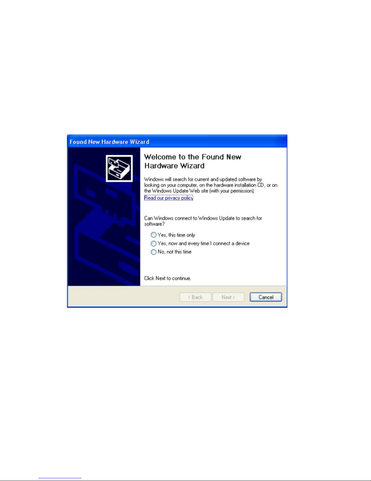
2. When Windows is loading, it will pop up a window “Found New Hardware Wizard” .
Click the “Cancel” button.
(For Windows 2000 and XP users)
Page 4
4 User Manual V1.0
1.1.1 Software Installation for AU-4000
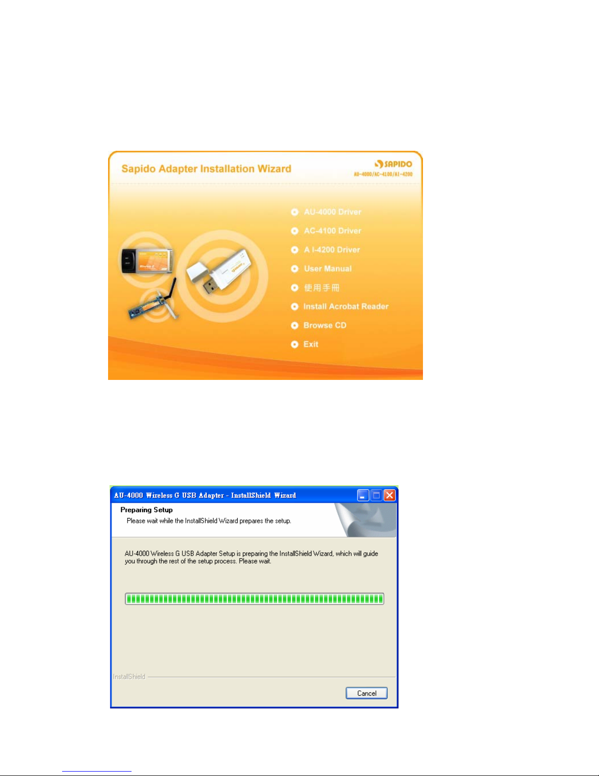
1. Insert the provided installation disc into your DVD/CD-ROM drive. The following
window will pop up.
2. Select “AU-4000 Driver”.
3. The setup program should be launched and bring you to Install Shield Wizard
window. Please click on “Yes” to continue.
Page 5
5 User Manual V1.0
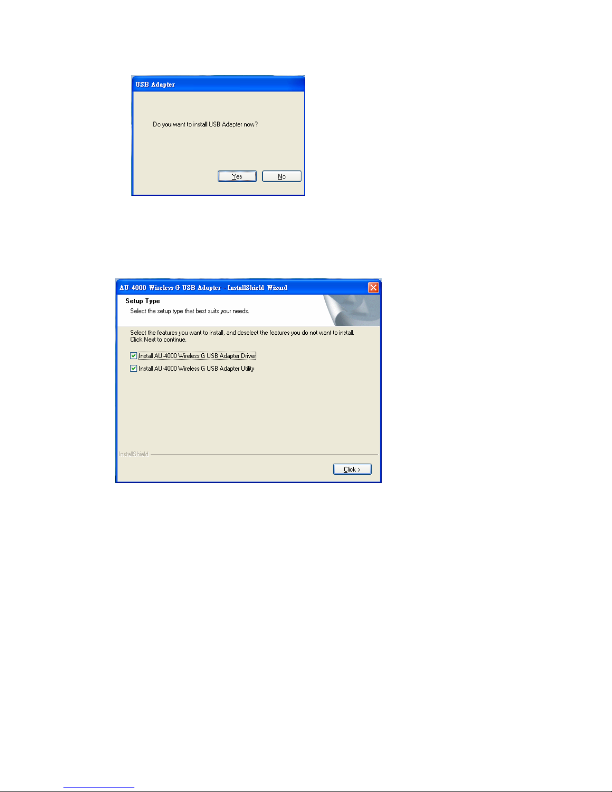
4. Windows 98 SE, ME, and 2000 users, please skip here and go to step 5. For
Windows XP users you’ll have two options. Please click on the selection to
choose your requirement, and then click the “Click” button.
5. The software installation should be processed. This may take a few minutes. For
Windows 98 SE users, insert your Windows 98 SE disc when prompting.
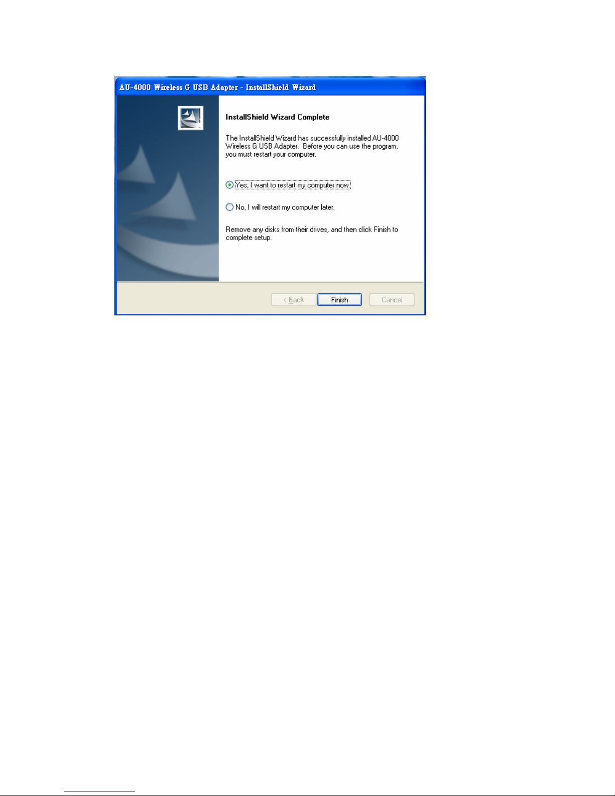
6. Once the installation is completed, you will be asked to restart your system
promptly. Click on “Yes” to restart your system (recommended). Otherwise,
click “No” and restart your system later.
Page 6
6 User Manual V1.0
7. Once yo ur system has restarted, you may now configure y our wireless network.
Page 7

7 User Manual V1.0
1.1.2 Software Installation for AC-4100
1. Insert the provided installation disc into your DVD/CD-ROM drive. The following
window will pop up.
2. Select “AC-4100 Driver”.
3. The setup program should be launched and bring you to Install Shield Wizard
window. Please click on “Yes” to continue.
Page 8
8 User Manual V1.0
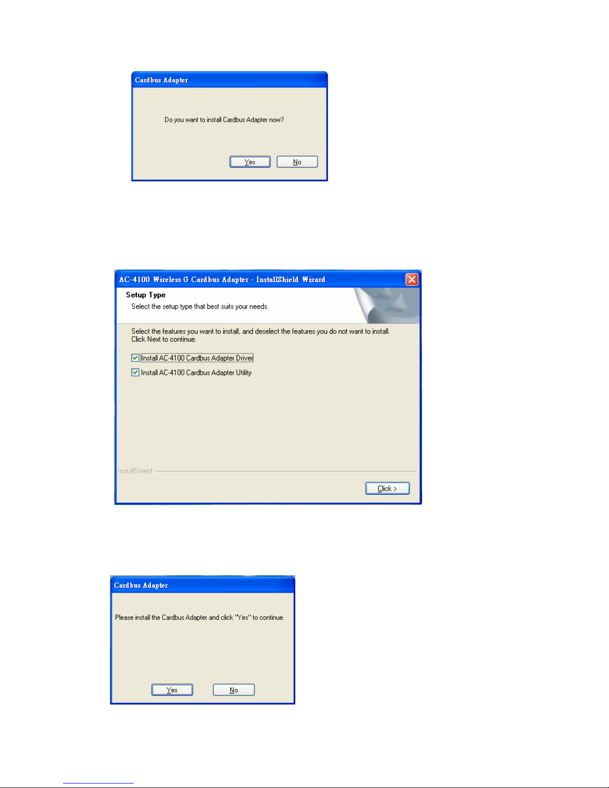
4. For Windows 98 SE, ME, and 2000 users, please skip and go to step 5. For
Windows XP users you’ll have two options. Please click on the selection to
choose your requirement, and then click the “Click” button.
5. When you see this window, please click “Y es” to continue and then the software
installation should be processed. This may take a few minutes. For Windows 98
SE users, insert your Windows 98 SE disc when prompting.
Page 9
9 User Manual V1.0
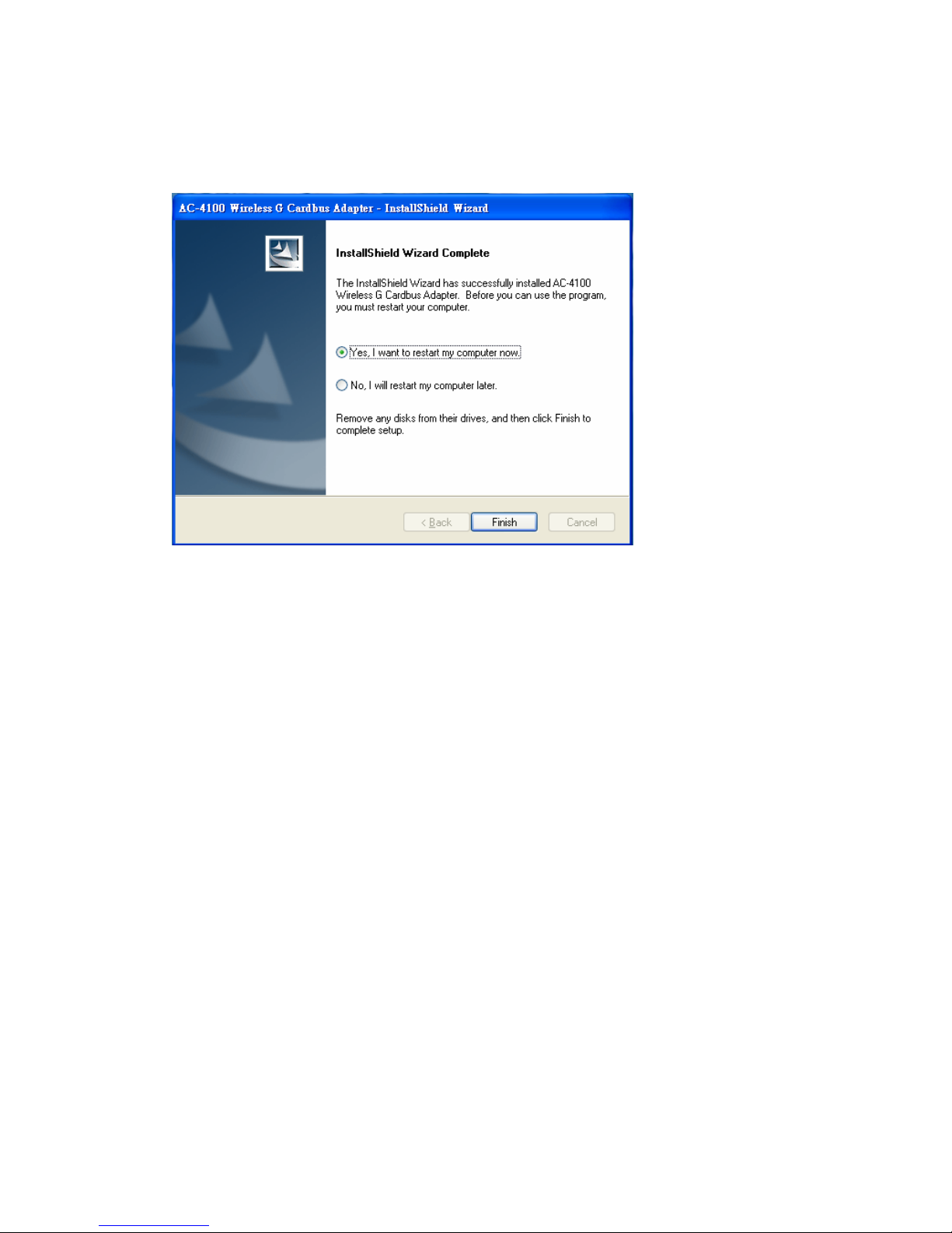
6. Once the installation is completed, you will be asked to restart your system
promptly. Click on “Yes” to restart your system (recommended). Otherwise,
click “No” and restart your system later.
7. Once your system has restarted, you may now configure your wireless network.
Page 10
10 User Manual V1.0
1.1.3 Software Installation for AI-4200
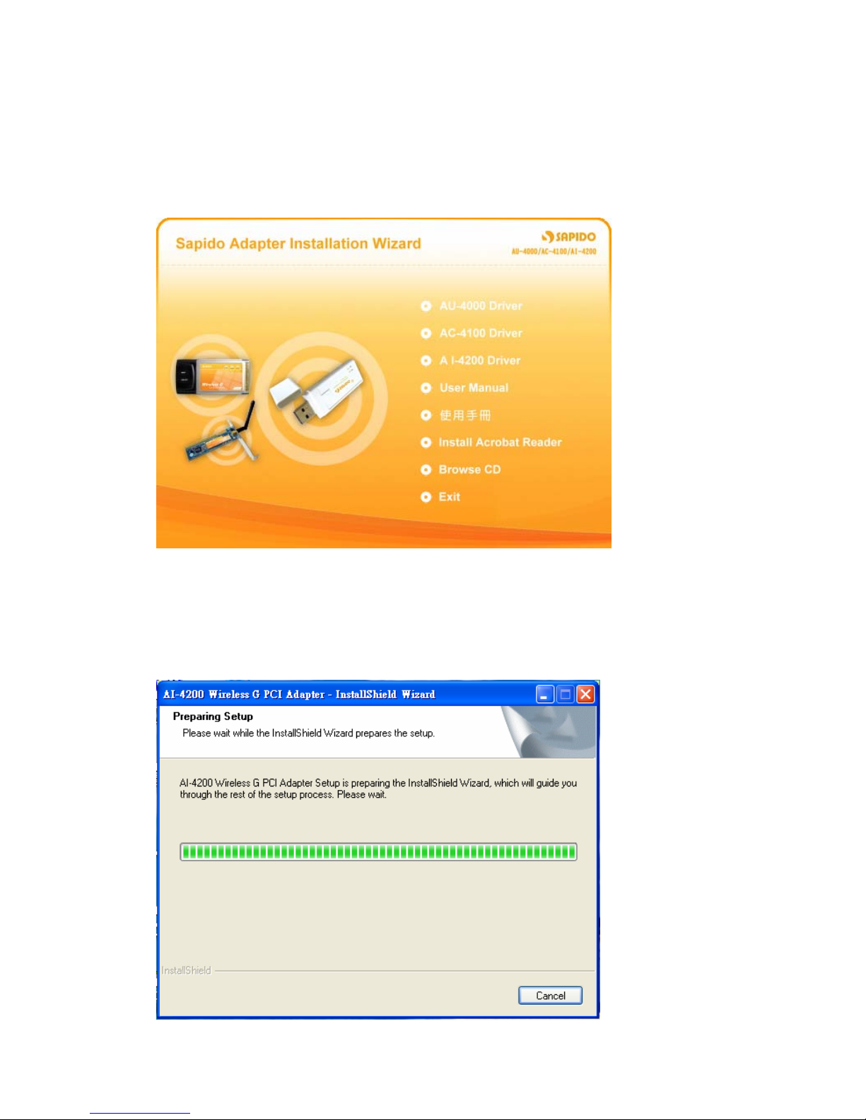
1. Insert the provided installation disc into your DVD/CD-ROM drive. The following
window will pop up.
2. Select “AI-4200 Driver”.
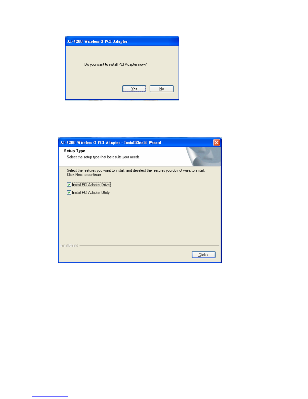
3. The setup program should be launched and bring you to Install Shield Wizard
window. Please click on “Yes” to continue.
Page 11
11 User Manual V1.0
4. For Windows 98 SE, ME, and 2000 users, please skip here and go to step 5. For
Windows XP users you’ll have two options. Please click on the selection to suit
your demand. Once you’ve made your selection, click the “Click” button.
5. The software installation should begin. This may take a few minutes. For
Windows 98 SE users, insert your Windows 98 SE disc when prompted.
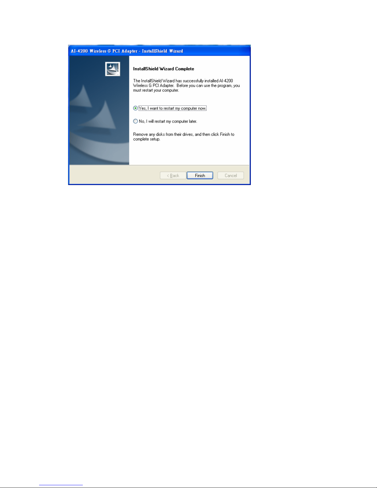
6. Once the installation is completed, you will be asked to restart your system
promptly. Click on “Yes” to restart your system (recommended). Otherwise,
click “No” and restart your system another time.
Page 12
12 User Manual V1.0
7. Once your system has restarted, you may now configure your wireless network.
Page 13
13 User Manual V1.0
1.2 Configuring Your Wireless Network (With Wireless Utility)
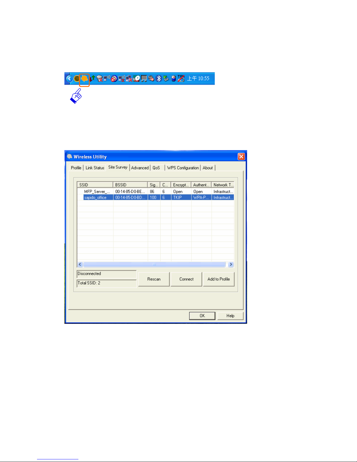
1. Sapido wireless signal icon will be shown in your taskbar, double click on it.
2. It should pup up the utility window. First, click on the “Rescan” button to scan
your area for available wireless network. Once the scan is completed, select the
desired wireless network from the list and click “Add to Profile” button.
4. It should pop up the Profile window. If you do not have any wireless security (WEP,
WPA, WPA2, and etc.) set on your wireless network, simply click the “OK” button
and go to step 6 directly . If yo u do have wireless securities setting on your wireless
network, then please click on the “Authentication and Security” tab.
Page 14

14 User Manual V1.0
5. Please set up your wireless securities settings, when completing, click the “OK”
button.
- If you have WEP, typically you only enter your WEP key in Key#1.
- If you have WPA, typically you only enter your WPA key in the WPA
Preshared Key.
Page 15

15 User Manual V1.0
6. You should now see the profile created, and then select the profile page and click
the Activate button to establish a wirele ss connection. The green box next to the
profile indicates you have connected and may close the Wireless Utility window
by clicking the“OK” button. Note: We recommend Windows 98 SE and ME users
to restart their system after activating the profile.
Page 16

16 User Manual V1.0
1.3 Configuring Your Wireless Network (With Microsoft Zero
Configuration Tool)
Warning: Due to security reasons, we strongly recommend upda ting Windows XP to
service pack 2 and above, if you have not done so. If you do not wish to
update, please use the Wireless UtilityⅠ-by right clicking on the taskbar
icon and selecting“Use Configuration as Configuration Utility”.
1. Right click on the computer with Sapido wireless signal icon in your taskbar.
Click on “Use Zero Configuration as Configuration utility”, and then it will be
changed to “Use Config as Configuration utility”, and now you are using
Windows Local Area Connection to set up the wireless network.
2. Click on Windows wireless connection icon to begin the setup.
Page 17

17 User Manual V1.0
3. Available wireless network SSID in range will be listed, please choose one
wireless network you would like to connect.
4. If the wireless network has wireless security settings, it will prompt you to type
in the wireless network key. Type in the “wireless Network Key” and retype the
wireless network key in the “Confirm Network K ey”. The network k ey i s usually
your WEP key or your WPA-PSK key.
Page 18

18 User Manual V1.0
5. Once the wireless network is displayed as”Co n nected”, which means y o u ha v e
successfully connected to your wireless network.
Page 19

19 User Manual V1.0
1.4 Uninstalling The Software
1. Click on your start menu. Next go to “Programs” or “All Programs”. Next go to
the folder “AU-4000 USB Adapter”. Next select “Uninstall”.
2. The uninstall window will pop up. Click on “Yes” button.
Page 20

20 User Manual V1.0
3. The uninstall process should begin and may take a few minutes. Once
completed, click “Yes” to restart your system (recommended). Otherwise, click
“No” to restart your system later.
Page 21

21 User Manual V1.0
Chapter 2 Configuration Operation
2.1 Star Configuration Utility
When starting Configuration and selecting “Use Configuration (Without 802.1x
support)” for the first time, system will connect to the AP with best signal strength
and matching security setting. When starting Configuration, it will issue a scan
command to wireless NIC. After two seconds, the list will updated with the result of
BSS list scan. The list include most used fields, such as SSID, signal percentage,
channel used, encryption status, authentication mode, and network type . The green
handshake icon indicates the connected BSS or IBSS network. The page is shown as
below.
Page 22

22 User Manual V1.0
2.2 Site Survey Page
Under the site survey page, system will display the information of surrounding APs
from last scan result. List information includes SSID, BSSID, Signal, Channel,
Encryption algorithm, and Network type as below.
1. Definition of each field
①
. SSID: Name of BSS of IBSS network.
②
. BSSID: MAC address of AP or randomly generated of IBSS.
③
. Signal: Receive signal strength of specified network.
④
. Channel: Channel in use.
⑤
. Encryption: Encryption algorithm used within than BSS or IBSS. Valid value
includes WEP, TKIP, AES, and Not Use.
⑥
. Authentication: Authentication mode used within the network, including
Unknown, WPA-PSK, WP A2-PSK, WPA and WPA2.
⑦
. Network Type: Network type in use, Infrastructure for BS S , Ad-Hoc for IBS S
network.
Page 23

23 User Manual V1.0
2. Connected network:
①
. When Configuration first ran, it will select the best AP to connect
automatically.
②
. If user wants to connect to other AP. He can double click mouse on the
intended AP to make connection.
③
. If the intended network has encryption other than “Not Use” Configuration
will bring up the security page and let user input the appropriate
information to make the connection.
This icon indicates the change is successful.
3. Indicate connection status, the connected network SSID will show up here.
4. Issue a rescan command to wireless NIC to update information on surrounding
wireless network.
5. Command to connect to the selected network.
6. Add the selected AP to Profile setting. It will bring up profile page and save user
setting to a new profile.
Page 24

24 User Manual V1.0
ADD/EDIT Profile
1. System Configuration as below figure shown.
①
. Profile Name: User chose name for this profile.
②
. SSID: User can key in the intended SSID name or use pull down menu to
select from available APs.
③
. Power Save Mode: Choose from CAM (Constantly Awake Mode) or Power
Saving Mode. There is a check box for AM when AC power? When this is
checked, the wireless NIC will stay full power when AC power cord is plug into
power outlet.
④
. Network T ype: There are two t ypes, infrastructure and 80 2.11 ad-hoc modes.
Under ad-hoc mode, user can also choose the preamble type; the available
preamble type includes short and long. In addition to that, the
『
channel』and
『
Ad hoc wireless mod』field will be available for setup in ad-hoc mode.
Page 25

25 User Manual V1.0
⑤
. TX Power: Transmit power, the amount of power used by a radio transceiver to
send the signal out. User can choose power value by sliding the bar.
⑥
. Preamble: There are three types, Auto, Long and Short are supported.
⑦
. RTS Threshold: User can adjust the RTS threshold number by sliding the bar
or key in the value directly. The default value is 2347.
Fragment Threshold: User can adjust the FRG threshold number by sliding the
bar or key in the value directly. The default value is 2346.
Page 26

26 User Manual V1.0
2.3 Encryption Setting [WEP/TKIP/AES]
Authentication & Security setting, shown as below figure.
1. Authentication T ype: There are three type of authe ntication modes supported by
Configuration. They are open, Shared, WPA-PSK and WPA system.
2. 802.1x Setting: It will display to set when user use radius server to authenticate
client certificate for WPA authentication mode.
3. Encryption Type: For open and shared authentication mode, the selection of
encryption type are None and WEP. For WPA, WPA2, WPA-PSK and WPA2-PSK
authentication mode, the encryption type supports both TKIP and AES.
4. WPA Pre-shared Key: This is the shared secret between AP and STA. F or WPA-PSK
and WPA2-PSK authentication mode, this field must be filled with character longer
than 8 and less than 32 length.
Page 27

27 User Manual V1.0
5. WEP Key: Only valid when using WEP encryption algorithm. The key must
matched AP key. There are several formats to enter the keys.
①
. Hexadecimal (40bits): 10 Hex characters.
②
. Hexadecimal (128bits): 32Hex characters.
③
. ASCII (40bits): 5 ASCII characters.
④
. ASCII (128 bits): 13 ASCII characters.
6. Show Password: Password would be shown on the screen.
Page 28

28 User Manual V1.0
2.4 802.1x Authentication
802.1x is an authentication for [WPA] and [WPA2] certificate to server. Show as
blow figure.
1. Authentication type:
①
. PEAP: Protect Extensible Authentication Protocol. PEAP transport securely
authentication data by using tunneling between PEAP clients and an
authentication server. PEAP can authenticate wireless LAN clients using only
server-side certificates, thus simplifying the implementation and
administration of a secure wireless LAN.
②
. TLS/Smart Card: T ransport Layer S ecurity . Provides for certificate-based and
mutual authentication of the client and the network. It relies on client-side and
server-side certificates to perform authentication and can be used to
dynamically generate user-based and session-based WEP keys to secure
subsequent communications between the WLAN client and the access point.
Page 29

29 User Manual V1.0
③
. TTLS: Tunneled Transport Layer Security. This security method provides for
certificate-based, mutual authentication of the client and ne twork through an
encrypted channel. Unlike EAP-TLS, EAP-TTLS requires only server-side
certificates.
④
. LEAP: Light Extensible Authentication Protocol. It is an EAP authentication
type used primarily in Cisco Aironet WLANs. It encrypts data transmissions
using dynamically generated WEP keys, and supports mutual authentication.
⑤
. MD5-Challenge: Message Digest Challenge. Challenge is an EAP
authentication type that provides base-level EAP support. It provides for only
one-way authentication - there is no mutual authentication of wireless client
and the network.
2. Session Resumption: user can choose “Disable” and “Enable”.
3. Identity and Password: Identity and password for server.
4. Use Client Certicate: Client Certicate for server authent icat ion.
5. Tunnel Authentication Protocol: Tunnel protocol, list information
including”AP-MSCHAP”, ”AP-MSCHAP v2”, ”AHAP” and “MD5”
6. Tunnel Identity: Identity for tunnel.
7. Tunne l Password: Password for tunnel.
Page 30

30 User Manual V1.0
2.5 CA Server Setting
Depending on the EAP in use, only the server or both the server and client may be
authenticated and require a certificate. Server certificates identify a server, usually
an authentication or RADIUS server to clients. Most EA Ps require a certificate issued
by a root authority or a trusted commercial CA. Show as the figure.
1. Certificate issuer: Choose use server that issuer of certificates.
2. Allow intimidate certificates: It must be in the server certificate chain bet ween
the server certificate and the server specified in the certificate issuer must be field.
3. Server name: Enter an authentication sever root.
Page 31

31 User Manual V1.0
2.6 Profile Page
Profile can book keeping your favorite wireless setting among your home, office,
and other public hotspot. You may save multiple profiles, and activate the correct
one at your preference. Figure below shows the profile page setting.
1. Definition of each field:
①
. Profile: Name of profile, preset to PROF* (* indicate 1, 2, 3,).
②
. SSID: AP or Ad-hoc name.
③
. Cannel: Channel in use for Ad-Hoc mode.
④
. Authentication: Authentication mode.
⑤
. Encryption: Security algorithm in use.
⑥
. Network Type: Network type, including infrastructure and Ad-Hoc.
Page 32

32 User Manual V1.0
2. Connection status
Indicate connection is successful on currently activated profile.
Indicate connection is failed on currently activated profile.
Note: When use site survey to make the connection. None of the profile will have the
connection status icon.
3. Add a new profile.
4. Delete an existing profile.
5. Edit Profile.
6. Connect selected profile.
Page 33

33 User Manual V1.0
2.7 Link Status Page
Figure below is the link status page; it displays th e detail information current
connection.
1. Status: Current connection status. If no connection, if will show Disconnected.
Otherwise, the SSID and BSSID will show here.
2. Extra Info: Display link status and current channel in use.
3. Link Speed: Show current transmit rate and receive rate.
4. Throughput: Display transmits and receive throughput in unit of K bits/sec.
5. Signal Strength: Receive signal strength, user can choose to display as
percentage or dBm format.
6. Connect Information: Display IP Address, Phy_Address, Sub Mask and Default
Gateway.
Page 34

34 User Manual V1.0
2.8 Advance Page
Figure below shows advance setting page of Configuration.
1. Wireless mode: Select wireless mode. 802.11B only and 802.11 B/G mixed.
2. B/G Protection: ERP protection mode of 802.11G definition. User can choose from
Auto, On, and Off.
①
. Auto: STA will dynamically change as AP announcement.
②
. On: Always send frame with protection.
③
. Off: Always send frame without protection.
3. TX Rate: Manually force the Transmit using selected rate. Default is auto.
4. TX Burst: Proprietary frame burst mode.
Page 35

35 User Manual V1.0
5. Enable TCP Window Size: Enhance throughput.
6. Fast Roaming at: fast to roaming, setup by transmit power.
7. Enable CCX (Cisco Compatible eXtensions): support Cisco Compatible Extensions
function:
①
. LEAP turn on CCKM
②
. Enable Radio Measurement: can channel measurement every 0~2000
milliseconds.
8. Turn radio ON/OFF for FAA requirement.
: Indicate to turn on RF.
: Indicate to turn off RF.
9. Apply the above changes.
Page 36

36 User Manual V1.0
2.9 QoS Page
Figure below shows QoS Page of Configuration. It involves ”WMM Enable” , ”WMM Power Save Enable” and DLS setup. The introduction indicates as follow:
1. WMM Enable: Enable Wi-Fi Multi-Media.
2. WMM - Power Save Enable: Enable WMM Power Save.
3. Direct Link Setup Enable: Enable DLS (Direct Link Setup).
Page 37

37 User Manual V1.0
2.10 WPS Configuration Page
Below figure shows WPS configuration page.
1. WPS Configuration: The primary goal of Wi-Fi Protected Setup (Wi-F i Simple
Configuration) is to simplify the security setup and management of Wi-Fi networks.
An Enrollee supports the configuration setup usi ng PIN configuration method or PBC
configuration method through an internal or external Registrar.
2. WPS Site Survey: Display the information of surrounding APs with WPS IE from
last scan result. List information includes SSID, BSSID, Channel, ID (Device
Password ID), Authentication Type and Encryption Type.
3. Rescan: Issue a rescan command to wireless NIC to update information on
surrounding wireless network.
Page 38

38 User Manual V1.0
Information: Display the information about WPS IE on the selected network. List
information includes Authentication Type, Encryption Type, Config Methods, Device
Password ID, Selected Registrar, State, Version, AP Setup Locked, UUID-E and RF
Bands. Its detail follows WPS Information on AP.
4. PIN Code: 8-digit numbers for external Registrar or internal Registrar using PIN
method. Each NIC Wireless has only one PIN Code.
5. Table of Credentials: Display all of credentials got from the Registrar. List
information includes SSID, MAC Address, Authentication and Encryption Type.
Credentials are created as soon as each WPS success and deleted as soon as PIN or
PBC start.
6. Control items on credentials
①
. Detail: Information about Security and Key in the credential.
②
. Connect: Command to connect to the selected network inside credentials.
The active selected credential is as like as the active selected Profile.
③
. Rotate: Command to rotate to connect to the next network inside credentials.
④
. Disconnect: Stop WPS action and disconnect this active link. And then select
the last profile at the Profile Page if exist. If there is an empty Profile page, the
driver will select any non-security AP.
⑤
. Delete: Delete an existing credential. And then select the next credential if
exist. If there is an empty credential, the driver will select any non-security
AP.
7. PIN: Start to add to AP using PIN configuration method.
PBC: Start to add to AP using PBC configuration method.
*When you click PIN or PBC, please don’t do any rescan within two-minute
connection. If you want to abort this setup within the interval, restart PIN/PBC or
press Disconnect to stop WPS action.
Page 39

39 User Manual V1.0
8. WPS associate IE: Send the association request with WPS IE during WPS setup.
It is optional for STA.
WPS probe IE: Send the probe request with WPS IE during WPS setup. It is
optional for STA.
9. Progress Bar: Display rate of progress from Start to Connected status.
Status Bar: Display currently WPS Status.
Page 40

40 User Manual V1.0
2.11 About Page
About page display the wireless card and driver version information as below figure
shown.
Page 41

41 User Manual V1.0
Appendix 1. Country Channel Page
Classification Range
0: FCC CH1 ~ 11
1: IC(Canada) CH1 ~ 11
2: ETSI CH1 ~ 13
3: SPAIN CH10 ~ 11
4: FRANCE CH10 ~ 13
5: MKK CH14 ~ 14
6: MKKI (TELEC) CH1 ~ 14
7: ISRAEL CH3 ~ 9
Country Name Classification Range
Argentina 0 CH1~11
Australia 1 CH1~13
Austria 1 CH1~13
Bahrain 1 CH1~13
Belarus 1 CH1~13
Belgium 1 CH1~13
Bolivia 1 CH1~13
Brazil 0 CH1~11
Bulgaria 1 CH1~13
Canada 0 CH1~11
Chile 1 CH1~13
China 1 CH1~13
Colombia 0 CH1~11
Costa Rica 1 CH1~13
Croatia 1 CH1~13
Cyprus 1 CH1~13
Czech Republic 1 CH1~13
Denmark 1 CH1~13
Ecuador 1 CH1~13
Egypt 1 CH1~13
Estonia 1 CH1~13
Finland 1 CH1~13
France 3 CH10~13
France2 1 CH1~13
Germany 1 CH1~13
Page 42

42 User Manual V1.0
Greece 1 CH1~13
Hong Kong 1 CH1~13
Hungary 1 CH1~13
Iceland 1 CH1~13
India 1 CH1~13
Indonesia 1 CH1~13
Ireland 1 CH1~13
Israel 6 CH3~9
Italy 1
CH1~13
Japan 5 CH1~14
Japan2 4 CH14~14
Japan3 1 CH1~13
Jordan 3 CH10~13
Kuwait 1 CH1~13
Latvia 1 CH1~13
Lebanon 1 CH1~13
Latvia 1 CH1~13
Lebanon 1 CH1~13
Liechtenstein 1 CH1~13
Lithuania 1 CH1~13
Luxembourg 1 CH1~13
Macedonia 1 CH1~13
Malaysia 1 CH1~13
Mexico 0 CH1~11
Morocco 1 CH1~13
Netherlands 1 CH1~13
New Zealand 1 CH1~13
Nigeria 1 CH1~13
Norway 1 CH1~13
Panama 1 CH1~13
Paraguay 1 CH1~13
Peru 1 CH1~13
Philippines 1 CH1~13
Poland 1 CH1~13
Portugal 1 CH1~13
Puerto Rico 1 CH1~13
Romania 1 CH1~13
Page 43

43 User Manual V1.0
Russia 1 CH1~13
Saudi Arabia 1 CH1~13
Singapore 1 CH1~13
Slovakia 1 CH1~13
Slovenia 1 CH1~13
South Africa 1 CH1~13
South Korea 1 CH1~13
Spain 2 CH10~11
Sweden 1 CH1~13
Switzerland 1 CH1~13
Taiwan 0 CH1~11
Thailand 1 CH1~13
Turkey 1 CH1~13
United Arab Emirates 1 CH1~13
United Kingdom 1 CH1~13
United States of America 0 CH1~11
Uruguay 1 CH1~13
Venezuela 1 CH1~13
Yugoslavia 0 CH1~11
 Loading...