


INSTRUCTION MANUAL
CAPVEL-ICT
Capacitance Level Transmitter
Version 2.0

User Manual & Datasheet V 2.1
Contents
Revision History . . . . . . . . . . . . . . . . . . . . . . . . . . . . . . . . . . . . . . . . . . . . . . . . . . . 4
1 Introduction . . . . . . . . . . . . . . . . . . . . . . . . . . . . . . . . . . . . . . . . . . . . . . . . . . . . 5
2 Operating Principle . . . . . . . . . . . . . . . . . . . . . . . . . . . . . . . . . . . . . . . . . . . . . . . . 5
3 System Description . . . . . . . . . . . . . . . . . . . . . . . . . . . . . . . . . . . . . . . . . . . . . . . . 5
4 Features . . . . . . . . . . . . . . . . . . . . . . . . . . . . . . . . . . . . . . . . . . . . . . . . . . . . . . 5
5 Applications . . . . . . . . . . . . . . . . . . . . . . . . . . . . . . . . . . . . . . . . . . . . . . . . . . . . 5
6 Capvel-BT Features . . . . . . . . . . . . . . . . . . . . . . . . . . . . . . . . . . . . . . . . . . . . . . . . 5
7 Capvel-ICT Features . . . . . . . . . . . . . . . . . . . . . . . . . . . . . . . . . . . . . . . . . . . . . . . 5
8 Mechanical Specification . . . . . . . . . . . . . . . . . . . . . . . . . . . . . . . . . . . . . . . . . . . . . 6
9 Electrical Specification . . . . . . . . . . . . . . . . . . . . . . . . . . . . . . . . . . . . . . . . . . . . . . 6
10 Measurement Specification . . . . . . . . . . . . . . . . . . . . . . . . . . . . . . . . . . . . . . . . . . . 6
11 Installation Guidelines . . . . . . . . . . . . . . . . . . . . . . . . . . . . . . . . . . . . . . . . . . . . . . 7
11.1 Tank Mounting Installation . . . . . . . . . . . . . . . . . . . . . . . . . . . . . . . . . . . . . . . . . 7
12 Electrical Connections . . . . . . . . . . . . . . . . . . . . . . . . . . . . . . . . . . . . . . . . . . . . . . 7
13 Calibration . . . . . . . . . . . . . . . . . . . . . . . . . . . . . . . . . . . . . . . . . . . . . . . . . . . . 7
14 Error Display and Remedy . . . . . . . . . . . . . . . . . . . . . . . . . . . . . . . . . . . . . . . . . . . . 10
15 Menu and Description . . . . . . . . . . . . . . . . . . . . . . . . . . . . . . . . . . . . . . . . . . . . . . 11
16 RS-485 Serial Commands for Communication with Capvel . . . . . . . . . . . . . . . . . . . . . . . . . . . 12
17 Settings . . . . . . . . . . . . . . . . . . . . . . . . . . . . . . . . . . . . . . . . . . . . . . . . . . . . . . 13
18 Maintenance . . . . . . . . . . . . . . . . . . . . . . . . . . . . . . . . . . . . . . . . . . . . . . . . . . . 13
19 Support Training . . . . . . . . . . . . . . . . . . . . . . . . . . . . . . . . . . . . . . . . . . . . . . . . 13
20 Customer Support . . . . . . . . . . . . . . . . . . . . . . . . . . . . . . . . . . . . . . . . . . . . . . . . 13
List of Figures
1 Capvel . . . . . . . . . . . . . . . . . . . . . . . . . . . . . . . . . . . . . . . . . . . . . . . . . . . . . 5
2 Connection Diagram . . . . . . . . . . . . . . . . . . . . . . . . . . . . . . . . . . . . . . . . . . . . . . 5
3 Calibration . . . . . . . . . . . . . . . . . . . . . . . . . . . . . . . . . . . . . . . . . . . . . . . . . . . 8
4 Tank Strapping . . . . . . . . . . . . . . . . . . . . . . . . . . . . . . . . . . . . . . . . . . . . . . . . 9
R
Sapcon Instruments Pvt.Ltd.
2

User Manual & Datasheet V 2.1
List of Tables
1 Mechanical Specifications . . . . . . . . . . . . . . . . . . . . . . . . . . . . . . . . . . . . . . . . . . . 6
2 Electrical Specifcations . . . . . . . . . . . . . . . . . . . . . . . . . . . . . . . . . . . . . . . . . . . . 6
3 Measurement Specifications . . . . . . . . . . . . . . . . . . . . . . . . . . . . . . . . . . . . . . . . . . 6
4 Error Display and Remedy . . . . . . . . . . . . . . . . . . . . . . . . . . . . . . . . . . . . . . . . . . . 10
5 Menu . . . . . . . . . . . . . . . . . . . . . . . . . . . . . . . . . . . . . . . . . . . . . . . . . . . . . . 11
6 Menu . . . . . . . . . . . . . . . . . . . . . . . . . . . . . . . . . . . . . . . . . . . . . . . . . . . . . . 12
7 Percentage Level Information . . . . . . . . . . . . . . . . . . . . . . . . . . . . . . . . . . . . . . . . . 12
8 Configuring and Asking Sensor ID on Network . . . . . . . . . . . . . . . . . . . . . . . . . . . . . . . . 13
Sapcon Instruments Pvt.Ltd.
R
3

Revision History
Revision Date Author(s) Description
1.0 18 Jan 2014 RND First Version Editing
1.1 25 Aug 2014 MRK Applications Revision
1.2 28 Jun 2015 RND Features Revision
1.3 10 Dec 2015 RND Specs Revision
1.4 23 Jul 2016 RND Specs Revision
2.0 08 Jan 2017 BRND Revised Format
2.1 17 Sep 2017 BRND Branding Revisions
1
User Manual & Datasheet V 2.1
1
• Copyright: All content on this document, such as text, graphics, logos and images is the property of Sapcon Instruments Pvt. Ltd.
The selection, arrangement and presentation of all materials on this document and the overall design of this document is the exclusive
property of Sapcon Instruments Pvt. Ltd.
• The images shown in this manual may differ from the actual instrument / housing in terms of dimensions, color and design. Please refer
to GA drawings for dimensional details.
• Values (of performance) described in this manual were obtained under ideal testing conditions. Hence, they may differ under industrial
environment and settings.
General Instructions
• Instrument shouldn’t block the material filling inlet.
• Secure the cover of housing tightly. Tighten the cable glands. For side mounting, the cable glands should point downwards.
• For side mounting, provide a baffle to prevent the material from falling on the probe.
• When handling forks, do not lift them using their tines. While using them with solids, ensure that material size is less than 10mm.
• Deforming the shape of the tines may interfere with the fork’s operating frequency.
• Make all electrical connections as instructed in the manual. Don’t power on the device before verifying the connections.
R
Sapcon Instruments Pvt.Ltd.
4
User Manual & Datasheet V 2.1
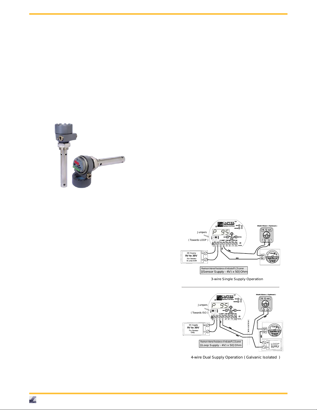
3-wire Single Supply O peration
mAmp
Maximum InternalR esistance of Indicator/PLC /Scanner
[(Sensor Supply - 4V) x 50] Ohm
Indicatoror
Scanner
orPLC
4-20mA
mAmp
MaximumInternal Resistanceof Indicator/PLC/Scanner
[(Loop S upply - 4V) x 50] O hm
Indicatoror
Scanner
orPLC
4-20mA
4-wire Dual Supply Operation ( Galvanic Isolated )
J umpers
( Towards ISO )
J umpers
( Towards LOOP )
I
S
O
L
A
T
I
O
N
1 Introduction
2 Operating Principle
CAPVEL is composed of specially developed capacitance change gauging circuit. It uses fast RISC based
processor to perform all the complicated jobs of evaluating the level out of the capacitance. This capacitance is
formed by the sense rod and the metallic container wall,
where containers are non-metallic or non-uniformly wide
or having turbulent fluid, a metallic stilling well is provided. The amount of capacitance is proportional to the
level of material between the sense rod and metallic wall
of stilling tube or container.
mA input or multimeter in 40 mA range or any-other
device that takes 4-20 mA signal as input.
4 Features
5 Applications
6 Capvel-BT Features
• User Interface : 2 DIP switches + 2 LED
• Output-1 : 4-20 mA, Galvanically Isolated
• Output-2 : Rs-485 Digital Data
7 Capvel-ICT Features
• User Interface : 4 Digit Display with 4 Keys + 2
LED
• Output-1 : 4-20 mA, Galvanically Isolated
• Output-2 : Rs-485 Digital Data
Figure 1: Capvel
3 System Description
CAPVEL is composed of cast aluminium housing,
supplied with suitable mounting arrangement viz.NPT,
BSP or Flanges and two metallic cable entries. An
external Earthing / Grounding terminal is also provided.
The sensing rod which is mostly Teflon coated. This
sensing rod can be replaced by flexible probe for some
applications. The stilling tube is also provided for
turbulent fluids, irregular width tanks, non-metallic
tanks or for fluids with low dielectric (e.g. diesel).
Opening the threaded aluminium cover, an electronic
insert could be found. This is the electronic unit which
converts the level into 4-20 mA signal depending on the
calibration. The status LED is a bi-color LED that blinks
alternately in Red and Green to indicate instrument is in
process of converting the level to 4-20 mA signal. Two
DIP switches are provided to calibrate the 4 mA and
20 mA points. The calibration is easy and a complete
procedure is given in "Calibration" page. The two wires
connected at the back are pre-connected sensor wires
and should not be disturbed. Also while calibration try
to keep hands away from the wires of terminal 6 and 7.
Now referring to the "Connection Diagram", Capvel can
be wired in two possible combinations. Preferred one
is galvanically isolated, 4-wire combination where only
one source of power is available, 3-wire, non-isolated
combination can also be used. The converted level signal
can be sensed using a 4-20 mA indicator or PLC 4-20
• Output-3 : Controlling Devices connected with External Relay
Figure 2: Connection Diagram
Sapcon Instruments Pvt.Ltd.
R
5

User Manual & Datasheet V 2.1
8 Mechanical Specification
For Mechanical Specification please refer Table 1
PARAMETER VALUE
Housing Cast aluminium weather and Flame proof suitable for
mounting in hazardous area Gas Group IIA and IIB as per
IS-2148
Mounting
• Integral with sense rod or probe with SS /MS(plated)
• Screw - 1"/1 1/2" BSP/NPT (M)
• Flanged - (As per your order)
Cable Entry 2 X 1/2"/3/4" BSP/NPT, Brass
Gland type Double Compression Gland
Sensing Fully or Partially Teflon Coated Rod, Flexible Probe SS316
Stilling Tube Pipe, GI / SS
Overall Dimensions Please refer enclosed probe drawing
Table 1: Mechanical Specifications
9 Electrical Specification
For Electrical Specification please refer Table 2
PARAMETER VALUE
Mains
• Capvel-BT : 9V to 55V DC
• Capvel-ICT : 9V to 30V DC
Power Consumption
• Capvel-BT : Max. 0.5 watt @12 V
• Capvel-ICT : Max. 1 watt @12 V
Table 2: Electrical Specifcations
10 Measurement Specification
For Measurement Specification please refer Table 3
PARAMETER VALUE
Measurement Span 15 to 3000 pf above Zero
Response Time 0.5 to 5 secs.( Adjustable )
Accuracy +/- 1% FSL or better
Electronics Ambient Temp. 0◦C. to +60◦C
Fail-Safe Feature Reverse Calibratable (Low Level: 20 mA, High Level: 4
mA)
Table 3: Measurement Specifications
R
Sapcon Instruments Pvt.Ltd.
6

11 Installation Guidelines
Note:
During installation, all electrical connections must
be powered OFF and the fuel tank must be empty.
User Manual & Datasheet V 2.1
11.1
Tank Mounting Installation
Note:
It is recommanded that the tank must be empty
while following steps in this section.
12 Electrical Connections
13 Calibration
Sapcon Instruments Pvt.Ltd.
R
7

User Manual & Datasheet V 2.1
0% Level
100% Level
Fill the tank at Low Level
0% Level
100% Level
1
2
3
Lower C alibration has done !
1
Calibr ating L ower L evel
Pr ocedure of Calibration
When material is at 0% or 4mA level.
Now the S ensor is in RU N MODE again !
We can Calibrate 4mA and 20mA in any order according to our c hoice.
The order o f empty-fill or fill-empty is immaterial.
Calibr ating HIG H L evel
Upper Calibration has done !
DOWN
2
Press and Hold T his K ey
UP
For 3 Seconds
Wait for around 5 Seconds
3
Wait for around 5 Seconds
Press and Hold T his K ey
For 3 Seconds
Fill the tank at High Level
High-SCAL %
Low-SCA L%
Figure 3: Calibration
Sapcon Instruments Pvt.Ltd.
R
8
User Manual & Datasheet V 2.1
0%
43.75%
100%
4.0mA
11.0mA
20.0mA
14 L (Offset)
72+6=78 L
=28/7=4 L /mA (Linear)Volume/mA
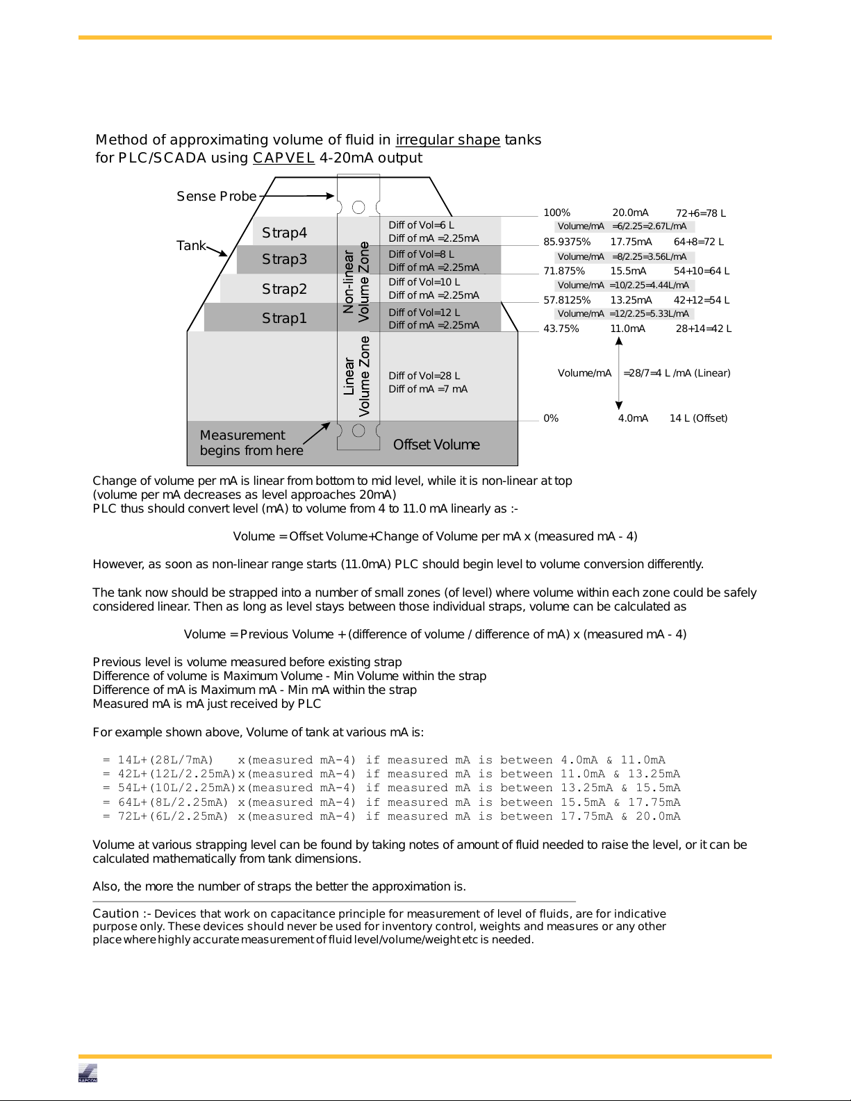
Change of volume per mA is linear from bottomto mid level, while it is non-linear at top
(volume per mA decreases as level approaches 20mA)
PLC thus should convert level (mA) to volume from 4 to 11.0 mA linearly as :-
Volume =OffsetVolume+Change of Volume per mA x (measured mA - 4)
However, as soon as non-linear range starts (11.0mA) P LC should begin level to volume conversion differently.
The tank now should be strapped into a number of small zones (of level) where volume within each zone could be safely
considered linear. Then as long as level stays between those individual straps, volume can be calculated as
Volume =Previous Volume +(difference of volume / difference of mA) x (measured mA - 4)
Previous level is volume measured before existing strap
Difference of volume is Maximum Volume - Min Volume within the strap
Difference of mA is Maximum mA - Min mA within the s trap
Measured mA is mA just received by P LC
For example shown above, Volume of tank at various mA is:
= 14L+(28L/7mA) x(measured mA-4) if measured mA is between 4.0mA & 11.0mA
11.0mA & 13.25mA
= 54L+(10L/2.25mA)x(measured mA-4) if measured mA is between 13.25mA & 15.5mA
= 64L+(8L/2.25mA) x(measured mA-4) if measured mA is between 15.5mA & 17.75mA
= 72L+(6L/2.25mA) x(measured mA-4) if measured mA is between 17.75mA & 20.0mA
= 42L+(12L/2.25mA)x(measured mA-4) if measured mA is between
Volume at various strapping level can be found by taking notes of amount of fluid needed to raise the level, or it can be
calculated mathematically from tank dimensions.
Also, the more the number of straps the better the approximation is.
Strap1
Strap2
Strap3
Strap4
Offset Volume
57.8125%
71.875%
85.9375%
28+14=42 L
Diff of mA =2.25mA
Diff of Vol=12 L
Diff of mA =2.25mA
Diff of Vol=10 L
Diff of mA =2.25mA
Diff of Vol=8 L
Diff of mA =2.25mA
Diff of Vol=6 L
13.25mA
15.5mA
17.75mA
42+12=54 L
54+10=64 L
64+8=72 L
Volume/mA =12/2.25=5.33L/mA
Volume/mA =10/2.25=4.44L/mA
Volume/mA =8/2.25=3.56L/mA
Volume/mA =6/2.25=2.67L/mA
Diff of mA =7 mA
Diff of Vol=28 L
Measurement
begins from here
Tank
Sense P robe
Method of approximating volume of fluid in tanks
for P LC/SC ADA using 4-20mA output
irregular shape
CAP VEL
Caution :- Devices that work on capacitance principle for measurement of level of fluids, are for indicative
purpose only. These devices should never be used for inventory control, weights and measures or any other
placewhere highly accuratemeasurementof fluid level/volume/weightetc is needed.
Figure 4: Tank Strapping
Sapcon Instruments Pvt.Ltd.
R
9

User Manual & Datasheet V 2.1
14 Error Display and Remedy
For Error Display and Remedy please refer Table 4
CODE ERROR DISPLAY ERROR DESCRIPTION TROUBLESHOOTING
1 PrOP Probes are OPEN circuited Check the probes with
multimeter
2 PrSC Probes are SHORT cir-
cuited
3 ECAL Calibration Error Calibration is wrong,
4 PrHI Over Capacitance Tank and probe dimen-
5 PrLO Under Capacitance Tank and probe dimen-
6 RFOP Internal reference got open
circuited
7 RFSC Internal reference got short
circuited
8 RFHI Internal reference satu-
rated
9 RFLO Internal reference negligi-
ble
10 OSC Oscillations stopped Internal fault in sensor
Check the probes with
multimeter
Please recalibrate correctly
sions are not matched
sions are not matched
Internal fault in sensor
Internal fault in sensor
Internal fault in sensor
Internal fault in sensor
Table 4: Error Display and Remedy
Sapcon Instruments Pvt.Ltd.
R
10

User Manual & Datasheet V 2.1
15 Menu and Description
For Menu please refer Table 5 and 6
MENU SUB MENU CHANGE DESCRIPTION REMARK
rLdr (Relay Drive) r. FS FS. H <>FS. L Fail Safe Selection
FS.H/ FS.L:Fail Safe
High/Low
rLdr (Relay Drive) r.oPt o.Ind<>o.PUM Control Action Selection
Ind : Individual, PUM :
Pump
rLdr (Relay Drive) r. SP S.000<>S.100 Set point Only in Indi-
vidual Controlling
rLdr (Relay Drive) r.SPH h.001<>h.100 Higher Set point Only in
Pump Controlling
rLdr (Relay Drive) r.SPL L.000 <>L.099 Lower Set point Only in
Pump Controlling
SPH must be higher
than SPL
SPH must be higher
than SPL
rLdr (Relay Drive) r.Cd C.000 <>C.100 Cover Delay in Seconds
rLdr (Relay Drive) r.Ud U.000 <>U.100 Uncover Delay in Sec-
onds
SCAL (Scal Factor) SC.-H H.020<>H.100 Higher SCALE LEVEL SCAL-HIGH must be
20% or more Higher
than SCAL-LOW
SCAL (Scal Factor) SC.-L L.000<>L.080 Lower SCALE LEVEL SCAL-HIGH must be
20% or more Higher
than SCAL-LOW
dISP(Display) d.PER<>d.AmP Display Options PER
: Percentage, AmP :
mAmp
Table 5: Menu
Sapcon Instruments Pvt.Ltd.
R
11

User Manual & Datasheet V 2.1
MENU SUB MENU CHANGE DESCRIPTION REMARK
trbu (Turbulence) t.001 <>t.010 Turbulence Immunity
vts (Vehicle Mode) 1 = ON 0 = OFF Immunity to vehicle gen-
erated fluctuations
c. ID Id.00 <>id.99 Communication ID of
Sensor on RS-485 Network
Com (Communication
Settings)
Com (Communication
Settings)
Com(Communication
Settings)
othr o.LEN LE0.0 <>LE9.9 Probe Length in meters Only for optimization
othr o.PRF PR.1 <>PRF.9 Profile Only for optimization
InFo i.SEr 12345678 Serial No Factory Sated and Read
InFo i.dAt 12345678 Mfd. Date in DD-MM-
c.bAU b.00.3<>b.38.4 Communication Baud
Rate 9.6 x 1000 =
9600bps and so on
c.Flo F.CMd<>F.AUt Flow Control
• CMD : Send data
when Commanded
• AUT : Send Data
Automatically
c.dur d.001<>d.250 Auto Data Sending Du-
ration in Seconds
YY format
Only usefully in Vehicle
Tracking Systems
(Flow : AUT)
Only
Factory Sated and Read
Only
Table 6: Menu
16 RS-485 Serial Commands for Communication with Capvel
For RS-485 Serial Commands please refer Table 7
COMMAND DESCRIPTION
Level would be calculated
by dividing incoming five
digit number with 10.Please
note that:- Application Software must have to take care
of any possible errors during turn-on or off durations,
change in nature of service
material etc.
COMMAND TO BE
SEND TO SENSOR
<A,PER?>or
<B,PER?>or
<a,PER?>or
<z,PER?>or
<Z,PER?>
Table 7: Percentage Level Information
EXPECTED RESPONSE
FROM INSTRUMENT
<A,PER=01000,H>
<B,PER=01000,N>
<a,PER=00625,N>
<z,PER=00000,N>
<Z,PER=00000,L>
EXPLAINATION
100.0% (OVER)
100.0% (NORMAL)
62.5% (NORMAL)
0% (NORMAL)
0%(LOW)
Sapcon Instruments Pvt.Ltd.
R
12

User Manual & Datasheet V 2.1
COMMAND DESCRIPTION
Asking single letter ID of instrument on RS-485 network
Setting single letter ID
of instrument on RS-485
network.Example-setting id
as:- ’A’ (Capital A)
COMMAND TO BE
SEND TO SENSOR
<*,ID?> <A,ID?-A> Instrument is telling it’s ID
<*,ID=A> <A,OK> ID is taken by instrument
Table 8: Configuring and Asking Sensor ID on Network
EXPECTED RESPONSE
FROM INSTRUMENT
EXPLAINATION
and this is the acknowledgement from it
17 Settings
18 Maintenance
19 Support Training
20 Customer Support
Thank you for going through the instructions given in this manual. To further ease the process of installation and use,
we have developed special demo videos which are hosted on YouTube.
Sapcon’s YouTube channel, SAPCON INSTRUMENTS, lists all these videos: https://goo.gl/dnxfcz
Should you require further information regarding installation, use or working of the instrument, please don’t hesitate
to contact us. Kindly provide the following information at the time of contacting:
• Instrument Model and Serial Number
• Purchase Order Number and Date of Purchase
• Description of the query
• Your contact details
In an attempt to serve you better, we are open seven days a week (9:30am to 7:30pm). We are available at:
• www.sapconinstruments.com
• sales@sapcon.in
• +91-731-4757575
Sapcon Instruments Pvt.Ltd.
R
13
 Loading...