

Sanyo Denki Sanups ASE-H series, ASE10S1HU001-10, ASE10S1HU001-15, ASE10S1HU001-20, PDASEU01 Instruction Manual
...
M0006244B
SANUPS ASE-H
ASE10S1HU001
ASE10S1HU001-10
ASE10S1HU001-15
ASE10S1HU001-20
Uninterruptible Power Supply Unit
PDASEU01
UPS Power Distribution Unit
100V Type
Instruction Manual

f
Introduction
Thank you for choosing the Model ASE10S1HU001,-10,-15,-20 and PDASEU01 UPS System.
SAVE THESE INSTRUCTIONS
This Manual contains important instructions for operating and maintaining the ASE10S1HU001
and PDASEU01 UPS System to protect the safety of the service technician and the customers.
Read it carefully before operating or maintaining the UPS system, to ensure personal safety and
proper device usage.
After reading, keep it in a place where it is easily accessible for reference.
This device is intended to be installed in a temperature-controlled indoor environment free o
conductive contaminants.
• Operating temperature: 0 to 40°C (32 to 104°F)
UPS is an abbreviation for Uninterruptible Power Supply
Table of contents
1. Safety Precautions .......................................................................................................................1
2. Considerations for Proper Operation.......................................................................................... 5
◆
2.1 Input Power Considerations ............................................................................................5
◆
2.2 Installation Considerations .............................................................................................5
◆
2.3 Usage Considerations ......................................................................................................5
◆
2.4 In Case of Trouble with the UPS..................................................................................... 6
3. Confirming Package Contents.....................................................................................................6
4. Overview....................................................................................................................................... 7
5. External Dimensions and Parts Names ..................................................................................... 9
◆
5.1 UPS Unit........................................................................................................................... 9
◆
5.2 Control Panel/Indicators................................................................................................ 10
◆
5.3 UPS Power Distribution Unit........................................................................................ 11
6. Carrying and Installation..........................................................................................................12
◆
6.1 Environment................................................................................................................... 12
◆
6.2 Carrying ..........................................................................................................................12
◆
6.3 Installation .....................................................................................................................12
7. Unit Settings and Wiring ..........................................................................................................13
◆
7.1 External Control Signals ...............................................................................................13
8. Preparations Before Operation .................................................................................................15
9. Operation.................................................................................................................................... 16
◆
9.1 Starting Operation (Normal Start) ...............................................................................16
◆
9.2 Starting Operation (Battery Start) ...............................................................................18
◆
9.3 Power Outage Simulation Test ......................................................................................20
◆
9.4 Operation Shutdown (Daily).......................................................................................... 21
◆
9.5 Operation Shutdown (If UPS is not to be used for a week or more) ...........................21
10. Operating and Protective Functions........................................................................................ 22
◆
10.1 Basic Operation ..............................................................................................................22
◆
10.2 Protective Functions ......................................................................................................24
◆
10.3 Protective Function Chart .............................................................................................26

11.
Maintenance and Inspection .....................................................................................................27
◆
11. 1 Daily Inspection.............................................................................................................. 27
◆
11. 2 Periodic Inspection .........................................................................................................27
◆
11. 3 Periodic Parts Replacement........................................................................................... 27
◆
11. 4 Battery Maintenance and Inspection............................................................................ 28
◆
11. 6 Fuse Replacement ..........................................................................................................28
12. Special Functions ....................................................................................................................... 29
◆
12.1 Battery Test ....................................................................................................................29
◆
12.2 User Settings ..................................................................................................................30
◆
12.2.1 PC Interface Selection.................................................................................. 32
◆
12.2.2 Communications Baud Rate Selection ........................................................32
◆
12.2.3 Power Outage Beeper Setting...................................................................... 33
◆
12.2.4 Frequency Sync Range Selection................................................................. 33
◆
12.2.5 Autostart After Power Recovery Setting.....................................................33
◆
12.2.6 INV ON/STAND BY Button Response Time Setting .................................34
◆
12.2.7 Ring Signal Start Setting............................................................................. 34
◆
12.2.8 Battery Starting Frequency Setting............................................................ 34
13. Specifications.............................................................................................................................. 35
14. Warranty Conditions.................................................................................................................. 36
Appendix .....................................................................................................................................37
■
SANYO DENKI Co., Ltd. Head office, branch offices

1. Safety Precautions
PRECAUTIONS
(IMPORTANT SAFETY INSTRUCTIONS)
SAVE THESE INSTRUCTIONS
Before installing, operating, performing maintenance or inspecting the UPS, be sure to read this
manual and accompanying documents carefully to obtain a clear understanding of the
information related to its operation, safety and important precautions.
This manual described two warning levels, DANGER and CAUTION, as described below.
DANGER
!
CAUTION
!
Additionally, even those hazards denoted by
so the instructions should be strictly followed.
The following labels indicate particularly important instructions which must be carefully
followed.
The graphic symbols indicate prohibited and mandatory actions.
Indicates actions that must not be allowed to occur (prohibited actions).
Indicates actions that must be taken (mandatory actions).
This example signifies that the equipment must be securely grounded.
Denotes immediate hazards which WILL probably cause severe bodily
injury or death, as a result incorrect operation.
Denotes hazards which COULD cause bodily injury and product or
property damage, as a result incorrect operation.
!
CAUTION could lead to a serious accident,
△
- 1 -

1. Installation Precautions
!
CAUTION
•
The UPS should be installed only by technically qualified personnel. Improper installation
can result in electric shock, bodily injury, and/or fire.
•
Never operate or store the UPS in the following environmental conditions. Doing so may
cause the UPS to malfunction, sustain damage or deteriorate, which could result in a fire.
a. In ambient environmental conditions other than those specified in the product brochure and
°
instruction manual (temperature 0 to 40
as in extremely high or low temperature and high humidity.
b. Where the UPS is exposed to direct sunlight.
c. Where the UPS is directly exposed to the heat from a heat source, such as a stove.
d. Where the UPS may be subject to vibration or physical shock.
e. Near a device that may emit sparks.
f. In the presence of dust, salt or corrosive or flammable gas.
g. Outdoors
•
Do not allow the air intake or exhaust vents to be obstructed. Keep the front and back of
the UPS at least 20 cm(7.88in) away from the wall. If the air intake or exhaust vent is
blocked, the internal temperature of the UPS rises, which could cause battery deterioration
resulting in a fire. During maintenance, the UPS requires at least 1 m (39.4in) space at the
front and 50 cm(19.69in) at the back.
•
The space around the UPS must be ventilated. Unless the specified ventilation airflow (5
3
m
/h) is maintained, gas produced by battery charging could result in rupture or explosion
of the case.
•
Install the UPS on a stable surface capable of bearing the weight of the UPS in the correct
manner specified in this manual.
•
If the UPS is installed incorrectly, impact or vibration could cause it to fall or move
inadvertently, resulting in bodily injury. Be careful to avoid back strain.
•
UL-Listed Branch circuit type overcurrent protection device rated min.250Vac, “2 Units
Par.:30A, 3 Units Par.: 40A, 4 Units Par.: 50A, 5 Units Par.: 70A” must be provided for
protection of the output and input ac circuit by qualified personnel .
C(32 to 104°F), relative humidity 30 to 90%), such
2. Wiring Precautions
!
CAUTION
•
Wiring should be performed only by technically qualified personnel. Incorrect wiring can
result in electric shock and/or fire.
•
Wire with the specified wire and the specified torque surely.
Ter mi nals Minimum Wire Size
Type
Input/Output/Ground 10 AWG 8 AWG 6 AWG 6 AWG Min. 75°C copper 3wire 4-4.5 N-m
No. of Parallel-Connected UPS Units
2 Units 3 Units 4 Units 5 Units
•
Connect the grounding cable securely in the manner specified. Failure to connect the
grounding cable may result in electric shock.
•
The grounding cables of all load devices* connected to the output of the UPS must be
securely connected to the grounding terminal. Failure to connect the grounding cables
correctly may result in electric shock.
* Load devices are devices such as computers that are connected to the UPS.
Tem pe rature
and
Material
Tor qu e
- 2 -

3. Operating Precautions
!
DANGER
•
Immediately shut the UPS off if it malfunctions, or if an unusual odor or noise is observed.
Failure to do so may result in a fire.
•
To avoid electric shock, do not open the cover of the UPS.
•
The space around the UPS must be well ventilated. Otherwise, gas produced by battery
charging could result in rupture or explosion of the case.
•
Before starting the UPS, make sure that the load side is safe. Be sure to refer to the
instruction manual while operating the UPS. The operating state of the UPS, as
determined by the ON/STAND BY switch, is indicated by the LEDs as shown the table
below. Check these indicators when operating.
Be careful when operating the ON/STAND BY switch. If power is supplied incorrectly, an
electric shock or bodily injury could result.
•
UPS status LEDs
STAND BY INPUT (on-green), OUTPUT (off-green)
ON INPUT (on-green), OUTPUT (on-green)
Avoid inserting sharp objects or fingers into the fan. Doing so may result in bodily injury.
!
CAUTION
PROHIBITED
•
Never use the UPS for the following types of loads:
a. Medical instruments used for life support.
b. Control units for trains or elevators, failure of which could cause bodily injury.
c. Computer systems upon which social or public infrastructure depends.
d. Devices which serve applications related to the above.
Contact your sales representative if you need to use the UPS in an application like the
above. Special equipment, such as redundant devices or an emergency generator must be
incorporated when operating, maintaining and controlling systems in which a UPS is used
with loads affecting life-support or public infrastructure-dependent applications.
•
Do not smoke or use an open flame near the UPS, as it could cause the UPS to explode or
rupture, resulting in injury or fire.
•
Do not place containers of liquid, such as a flower vase, on the UPS. If the container was to
spill, the liquid could cause a short circuit, resulting in sparks or fire inside the UPS.
•
Do not sit, step or lean on the UPS, as bodily injury could result if the UPS was to fall.
4. Maintenance and Inspection Precautions
!
CAUTION
•
Maintenance and repair of the inside of the UPS should be performed only by technically
qualified personnel. Electric shock, bodily injury and burns, fuming, or fire could otherwise
result.
•
Contact your nearest sales representative or authorized service center to have the UPS
checked out or to replace defective parts. Opening the cover carelessly can result in an
electric shock or burn.
•
Replace the batteries periodically (once every 4.5 years when operated at 25°C(77°F).
Using batteries after their service life has expired may cause a fire.
•
Do not allow sharp metallic objects or fingers to touch the battery connectors of the UPS.
Doing so may result in an electric shock.
•
Do not touch any parts inside the UPS, even when AC input is removed. Voltage produced
from the batteries can still cause an electric shock.
- 3 -

5. Relocation and Transportation Precautions
!
CAUTION
•
Be careful to avoid falling or dropping the UPS during relocation or transportation, as
bodily injury could result.
•
Be careful to avoid back strain when handling the UPS.
•
To avoid bodily injury caused by dropping the UPS, do not tilt it more than specified
degrees to either side when moving it. Take preventative measures to avoid dropping the
UPS if it must be tilted more than specified degrees when moving it.
Equipment type name
Angle of inclination (degree) 30 40 50 55
No. of Parallel-Connected UPS Units
2 Units 3 Units 4 Units 5 Units
6. Battery Handling Precautions
!
CAUTION
•
Battery servicing should be performed or supervised by technically qualified personnel
knowledgeable about batteries and the required precautions. Keep unqualified personnel away from
batteries.
•
Nominal battery voltage is 36 volts DC.
•
Replace batteries only with the same model and brand: HF7-12 manufactured by Shin-Kobe Electric
Machinery Co., Ltd.
•
Customers should not dispose of used batteries themselves. Contact your nearest sales
representative, authorized service center or sales office to dispose of used batteries.
•
Do not use batteries after their service life has expired. Doing so may result in fuming or fire.
Additionally, the battery backup function may fail to operate with such batteries, so that power will
not supplied to the load when a power outage occurs.
•
Batteries pose hazards for electrical shock and dangerous short-circuit current. The following
precautions should be observed when working with batteries:
a. Remove watches, rings and other metal objects.
b. Use insulated tools.
c. Wear rubber gloves and boots.
d. Do not lay tools or metal parts on top of batteries.
e. Disconnect the charging source prior to connecting or disconnecting battery terminals.
f. Determine whether the batteries have been inadvertently grounded, and if so, remove the source
•
•
•
•
•
of grounding. Contact with any part of a grounded battery can result in electric shock.
Do not attempt to open or disassemble batteries. The electrolyte is harmful to the skin and eyes. The
battery contains diluted sulfuric acid, which is extremely toxic. If a battery leaks, take appropriate
measures to prevent any battery fluid contacting your skin or clothing. Diluted sulfuric acid may
cause blindness if it gets into the eye, may burn skin upon contact. It is electrically conductive and
corrosive. Observe the following procedures if electrolyte spills:
a. Wear full eye protection and protective clothing.
b. If sulfuric acid contacts the skin, wash it off immediately with water.
c. If sulfuric acid contacts the eyes, flush thoroughly and immediately with water, and seek
medical attention.
d. Spilled sulfuric acid should be washed down with a suitable acid-neutralizing agent, such as a
solution of approximately one pound (500 grams) bicarbonate of soda in one gallon (4 liters) of
water. The bicarbonate of soda solution should be applied until evidence of reaction (foaming)
has ceased. The resulting liquid should be flushed with water and the area dried.
Lead acid batteries can present a risk of fire due to generation of hydrogen gas. The following
procedures should always be followed:
a. DO NOT SMOKE when near batteries.
b. DO NOT allow flames or sparks near batteries.
c. Before working with batteries, discharge static electricity from the body by first touching a
grounded metal surface before touching the batteries.
Do not dispose of batteries in fire, as they could explode.
If a fire occurs near a battery, do not use water to extinguish it. Use only a powder-distinguishing
agent (ABC). Using water can cause the fire to spread.
Strictly observe the following precautions when handling the batteries. Failure to do so may cause
battery leakage, overheating or explosion.
a. Do not solder to any part of the battery directly.
b. Do not charge the battery with reversed positive (+) and negative (-) terminal polarity.
c. Do not mix different battery types, brands or versions.
d. Do not attempt to peel off or break the outer covering of a battery.
e. Do not subject batteries to strong physical shock, or throw them away.
f. Clean batteries with water-moistened cloth. Do not use organic compounds such as gasoline,
thinner, benzene or detergent.
g. Electrical energy may remain in a battery even after its service life has expired.
Do not allow sparks near used batteries, and protect them from short-circuiting.
- 4 -

2. Considerations for Proper Operation
◆
2.1 Input Power Considerations
(1) The UPS version should match the AC line voltage (100, 110, 115 or 120 VAC ±15%,
and 50 or 60 Hz ±5%). Specific voltages and corresponding versions are as follows:
(2) The current capability of the AC supply must meet the requirements of the UPS (0.9
kVA to 4.5kVA). However, the circuit breaker in the source distribution panel should
be rated one grade higher than the load demand.
(3) Install the breaker (2 Units Par.: 30A, 3 Units Par.: 40A, 4 Units Par.: 50A, 5 Units
Par.: 70A) for the distribution board of the UL authorization.
◆
2.2 Installation Considerations
(1) Carefully consider the leakage current when a leakage circuit breaker is installed at
the input side. The leakage current of the UPS system is maximum 9 mA (5 UPS
Units in parallel).
(2) Keep the UPS at least one meter away from CRT displays. Other devices which may
be sensitive to magnetic flux should be kept away from the UPS, as it emits a slight
amount of magnetic flux.
(3) The UPS utilizes a fan for forced-air cooling. Provide at least 20 cm(7.88in) clearance
at the front and back of the UPS to permit free airflow at the air intake and exhaust
vents. For maintenance purpose, a space of at least one meter (39.4in) in front and 50
cm (19.69in) in the back of the UPS is needed. See “§6.3 Installation Space” for
details.
(4) If the AC source has one side grounded, the N terminal (phase) of the UPS must be
the grounded phase.
(5) If possible, avoid grounding the output (load) side. If one side must be grounded, the
V terminal (phase) should always be the grounded phase (to avoid short-circuiting
power to ground).
◆
2.3 Usage Considerations
(1) Never short-circuit the output terminals, or connect a load which draws short-circuit
current. Doing so causes protective functions or fuse opening to prevent output.
(2) Unsuitable load devices
Do not connect laser printers, plain paper fax machines, copy machines or overhead
projectors as load devices. Such devices typically include heating elements that draw
high current. This may cause an overload that could prevent battery backup
operation when an outage occurs, or damage the UPS.
(3) Power supply environment
If the UPS is used in an environment subject to long and frequent power outages
(more than once a week), the batteries may not receive sufficient charge, which could
result in foreshortened battery life and premature battery failure.
(4) If the UPS is not operated for 6 months or more, the battery may require charging
before use. Operate the UPS with no load for at least 20 hours once every 6 months.
(5) Insulation testing
Before testing indoor wiring insulation, shut down the UPS and disconnect the input
and output cables. Conducting an insulation test with the UPS connected may
damage electronic components such as the built-in arrester.
(6) The UPS is designed to be installed horizontally. However, if it must be installed
vertically, the left side should be the lower side (the indicators at the higher side),
and mounting brackets should be installed if needed.
For rack mounting, an optional mounting bracket is required. Please contact your
sales representative for details.
- 5 -

◆
2.4 In Case of Trouble with the UPS
If one of the following trouble indications occurs, contact your nearest sales
representative.
(1) The ALARM indication lamp lights red (except when the UPS shuts down during a
long power outage).
(2) The INV ON/STAND BY, INPUT and OUTPUT indicators don’t light green during
normal operation.
(3) When any other symptom suspected to be a sign of trouble is observed.
3. Confirming Package Contents
When opening the package, please confirm the proper contents and contact your nearest sales
representative if you find any discrepancy.
The package cartons are UPS Power Distribution Unit 1 set and Uninterruptible Power Supply
Unit (hereinafter referred to as UPS Unit) 2 to 5 set. (The set number of UPS Unit depends on
the unit number of parallel connection.)
The contents of each package are as follows.
(1) Package contents of UPS Power Distribution Unit (PDASE) per set
(a) UPS Power Distribution Unit 1 unit
(b) Accessories Instllation and Maintenance Manual 1 copy
Instruction Manual
Setting Manual 1 copy
PC Interface cable 1 pcs
Input/Output cable 5 pcs
Terminal cover A 1 pcs
Terminal cover B (Set in terminal cover A) 1 pcs
Cable cover (For UPS Unit) 1 pcs
Cable cover (For UPS Power Distribution Unit) 1 pcs
Screw for cable cover 1 pcs
Leg for vertical installation 4 pcs
Manual for leg 1 copy
(2) Package contents of UPS Unit (ASE10S1H) per set
(a) UPS Unit 1 unit
(b) Accessories Unit Interface cable 1 pcs
Coupling bracket 1 pcs
Screw for coupling bracket 2 pcs
Bypass Fuse 15A 1 pcs
Cable cover 1 pcs
Screw for cable cover 1 pcs
Ground plate 1 pcs
Leg for vertical installation 4 pcs
Manual for leg 1 copy
(this booklet) 1 copy
- 6 -

4. Overview
This uninterruptible power supply is designed to provide reliable and stable AC power to
critical equipment that requires continuous uninterrupted power.
This UPS system consists of 2 to 5 based 1kVA UPS Unit connected in parallel. According to
this configulatin, when customer system requires greater power capacity due to load expansion,
this UPS system capacity can be easily expanded by installing the additional UPS Units in the
range from 2 to 5 kVA.
Moreover, This system has a high reliability for uninterruptible power supplying to be able to
configure a N+1 operation for the "1-4kVA" load.
The UPS Unit consists of rectifier, charger, inverter, battery and utility power transfer (bypass)
circuits. In the event of failure of the AC source (utility power), inverter operation is
sustained by converted DC power supplied from the batteries. When the utility power recovers,
inverter operation continues while the battery is recharged. The UPS system is therefore able
to supply completely uninterruptible AC power to connected loads without so much as a
moment of power loss.
If a fault occurs in an inverter or the UPS output is overloaded, the output automatically
switches the source of AC power to the bypass circuit, without interruption, the utility power is
supplied to connected loads.
This UPS system consists of the basic 1 kVA UPS Unit including the batteries, up to 5 unit, and
UPS Power Distribution Unit.
- 7 -

A
A
C input
Ground
Bypass Fuse
Filter
Input
Fuse
Battery
UPS Unit No.1
UPS Unit No.2
UPS Unit No.3
UPS Unit No.4
UPS Unit No.5 (max)
Filter
UPS Power Distribution Unit
Rectifier
Charger
Bypass circuit
Inverter
DC/DC
Converte
Fuse
MAINTENANCE
BYPASS SW
(Optional)
Output Selector
Switch
Filter
Control Circuit
LAN I/F
(optional)
Contact
Signal
(optional)
REMOTE
PC I/F
CARD I/F
C Output
UPS system Block Diagram
- 8 -

5. External Dimensions and Parts Names
◆
5.1 UPS Unit
86mm [3.39in]
②
④
③
410mm [16.14in]
⑤
⑧
⑥
(behind cover)
⑨
①
⑦
UNIT SW
ON
OFF
Depth: 435 mm (17.13 in)
Weight: 19 kg (41.89 lbs)
No. Name Marking Function
①
Control Panel, Indicators – Operating controls and indicators
②
Unit Interface UNIT I/F
③
Card Interface CARD I/F
④
PC Interface PC I/F For PC or workstation communications
⑤
Cooling Fan - Cooling
⑥
Optional Card Slot OPTION CARD Compartment for installing optional card
⑦
Unit Switch UNIT SW Input power on/off for UPS Unit
⑧
Remote On/Off Connector
⑨
Bypass Fuse BYPASS FUSE Bypass circuit protection fuse
REMOTE Connection terminal for remote On/Off switch
For inter-unit connections with Unit Interface
Cables
For connecting external communications and
card options
- 9 -

① ③ ⑤ ⑦
⑥ ⑩
◆
5.2 Control Panel/Indicators
⑪
⑫
②
⑧
④
⑨
No. Name Marking Function
INV ON/STAND BY
①
Switch
INV ON/STAND BY
②
Indicator
③
Clear Switch CLEAR Silences the beeper and clears battery test results
④
Battery Test Switch BATT.TEST Starts and stops a battery test
⑤
Battery Test Indicator
⑥
Alarm Indicator ALARM
⑦
Input Indicator INPUT
⑧
Output Indicator OUTPUT
⑨
Load Level Indicator LOAD LEVEL
⑩
Battery-Low Indicator BATT.LOW
Parallel Redundancy
⑪
Operation Indicator
N+1 Redundancy
⑫
Operation Indicator
In this manual, switch names are denoted as (e.g.: INV ON/STAND BY ).
INV
ON/STAND BY
-
-
P. R . O .
F. T.
Switches inverter operation on/off
Lights (green) when power is supplied through the
inverter, and blinks when supplied through the
bypass circuit
Blinks during battery test
Indicates battery test results:
LED on = normal result, LED blinking = abnormal,
LED off = stopped
Lights (red) if the UPS fails, and when the batteries
are discharged below minimum operating voltage
Lights (green) when input utility power is normal,
and blinks when input power is abnormal
Lights (green) when output power is supplied
through the inverter, and blinks when supplied
through the bypass circuit
Indicates the load level
(20, 40, 60, 100% or O.L [Overload])
Lights when battery voltage is low
Turns off when abnormal communications between
units occurs, or if the No. of Units is incorrectly set
Lights during N+1 redundancy operation
(lit when load level is below (N-1) kVA)
The status of LEDs on the control panel are indicated as for lit, and for blinking.
- 10 -
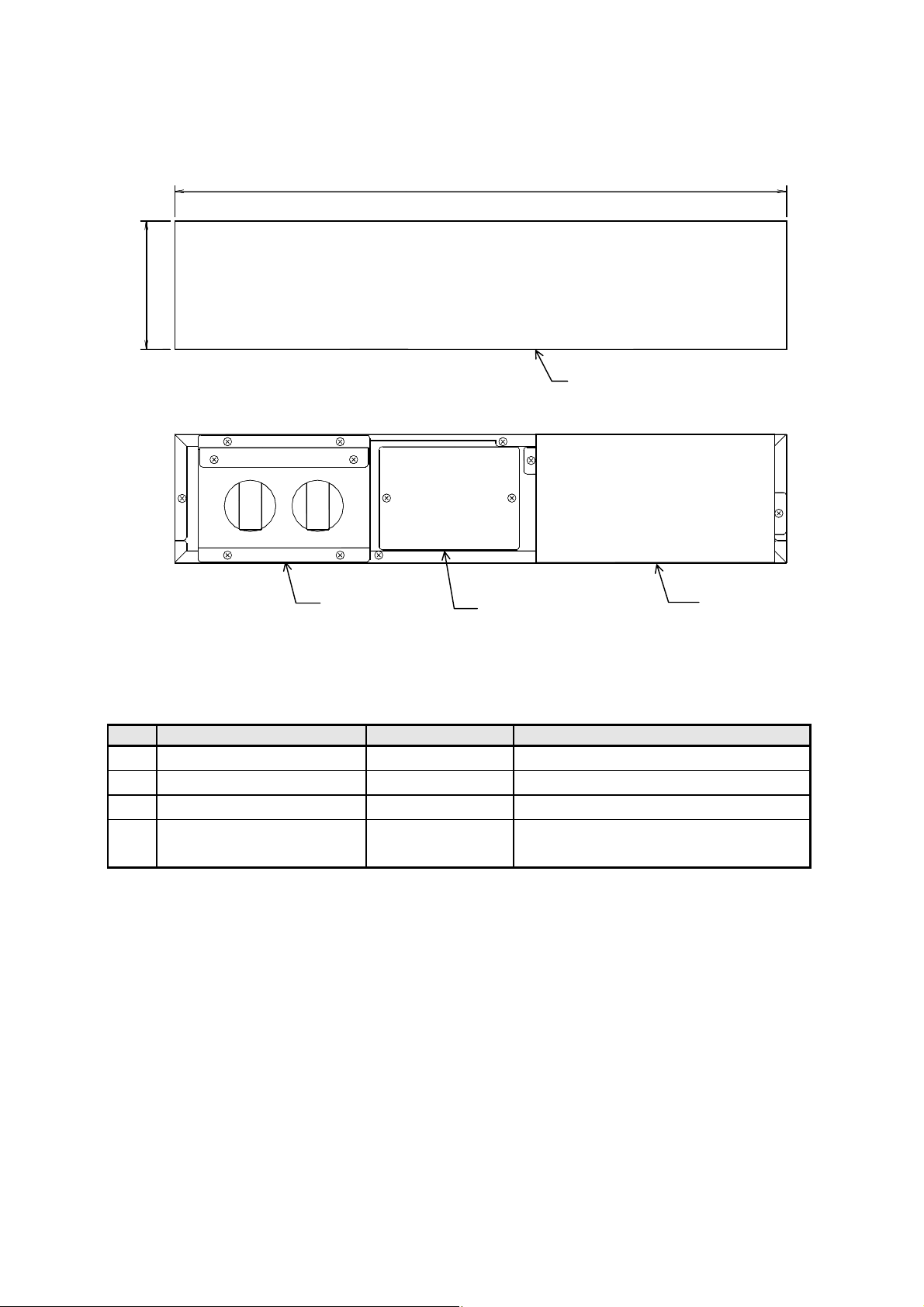
◆
5.3 UPS Power Distribution Unit
86mm [3.39in]
③
410mm [16.14in]
④
(Optional)
①
②
Depth: 410 mm (16.14 in)
Weight: 9 kg (19.84 lbs)
No. Name Marking Function
①
Front Panel - -
②
Cable Cover - -
③
Terminal Brock Cover - Maintenance Bypass Switch
④
(Optional)
MAINTENANCE
BYPASS SW
Molded case cam switch for
maintenance (normally OFF)
- 11 -

6. Carrying and Installation
Each UPS Unit weights about 19 kg (41.89 lbs), and the UPS Power
Distribution Unit weights about 9 kg (19.84 lbs).
Install the UPS on a stable surface that can bear the weight of all units.
•
This surface should be flat, so the UPS cannot fall and cause bodily injury.
•
The possibility of vibration and shock should be minimized at the
!
CAUTION
◆
6.1 Environment
Do not install the UPS in the following locations:
•
•
•
•
•
◆
6.2 Carrying
•
installation location.
Be careful to avoid lower back strain when carrying and installing.
•
•
The UPS might fall or be dropped during relocation or installation. Always
hold the UPS Units securely by the upper corners. Bodily injury could result
if a UPS falls to the floor.
Where the ambient temperature exceeds 40°C (104°F).
For optimum battery life, install the UPS where ambient temperature stays between
20 and 25°C (68 and 77°F ).
Where high humidity may occur.
Where corrosive gas or salt spray may be present.
Where it may be subject to vibration and shock.
Where dust may accumulate.
Carry the UPS within its packing cartons,
removing only when near the installation
Equipment type name
location.
•
To avoid bodily injury from dropping a UPS
!
CAUTION
Angle of inclination
Unit, do not tilt it more than specified
degrees to either side when moving it. Take
preventative measures to avoid dropping a
UPS if it must be tilted more than specified
degrees when moving it.
(degree)
◆
6.3 Installation
The UPS is designed to be installed either
horizontally in a rack or vertically on the floor.
When installed vertically, the left side (as viewed
from the front) should always be the lower side
(with the control panel at the upper side), and
the coupling brackets should be installed.
Provide the following space around the UPS
system.
•
At least 20 cm(7.88in) at the front
as air intake space for the cooling fan.
•
At least 20 cm (7.88in) at the back
as air exhaust space for the cooling fan.
•
At least 1 meter (39.4in) at the front and 50
cm (19.69in) at the back for maintenance
when needed
•
At least 1 meter(39.4in) from CRT displays to allow for slight leakage of magnetic
flux. Allow some space from devices which might be affected by magnetic flux.
No. of Parallel-Connected UPS Units
2 Units 3 Units 4 Units 5 Units
30 40 50 55
Maintenance space
At least 50cm(19.69in)
Exhaust space
At least 20cm (7.88in)
ASE
△
Front
Intake space
At least 20cm(7.88in)
Maintenance space
At least 1 m(39.4in)
- 12 -

7. Unit Settings and Wiring
•
Obtain the assistance of technically qualified personnel for wiring.
Incorrect wiring can result in electric shock, injury or fire.
•
!
CAUTION
◆
7.1 External Control Signals
(1) External Interface Connector (CARD I/F)
This connector is specially designed for use with Sanyo card options (network
interface card and contact-interface card). If you wish to use this connector for other
devices, please contact your nearest sales representative.
(2) PC/Workstation Interface Connector (PC I/F)
①
This connector can be used to control power by external communications from a
computer (such as a PC or workstation) using the optional SanGuard power
control software. Use the communications cable supplied with the UPS Power
Distribution Unit.
PC I/F Setting: W/S Mode (§12.2.1)
②
Signals are supported by the UPS monitoring functions of network operating
systems (such as Netware and Windows NT).
By connecting a computer (PC or workstation) with the communications cable
supplied with the UPS Power Distribution Unit, automatic shutdown can be
controlled by the UPS services in Windows NT.
PC I/F Setting: Stand-Alone Mode (§12.2.1)
Precautions for using UPS monitoring functions
In the UPS Configuration window of the operating system, the Remote UPS Shutdown
setting should be set to Positive. Refer to the documentation for your network
operating system for details.
If the operating system does not support UPS monitoring functions (such as Windows
95 and 98), do not use the communications cable supplied with the UPS Power
Distribution Unit, as backup will not occur in the event of a power outage.
Make sure the input and output terminals and external control plugs
are firmly connected. A loose connection can cause smoke or fire.
•
Make sure the ground terminal is connected to earth ground.
Otherwise, there is danger of electric shock.
- 13 -

(3) Remote ON/OFF Connector
This connector can be used for optional remote ON/OFF switching control.
Signal Name Description
Remote
ON/OFF
The UPS can be remotely switched on and off by closed-circuit contact
switching signals.
The contacts should be those of a device such as a push-button switch.
Remote ON/OFF
Connector
ON
REMOTE
COM
Signal Input
OFF
2
1
3
4
Remote ON:
start by pulse (closed contacts)
for at least 1 s.
Remote OFF:
stop by pulse (closed contacts)
for at least 1 s.
Mini DIN 6P
6 5
4 3
2 1
Circuit Voltage: 5V DC
Switching Current: about 12 mA
Operation is as follows according to the interface setting:
•
Stand-Alone Mode: Remote ON/OFF
•
Workstation Mode: Remote ON/One-Touch Shutdown
Precautions for using Remote ON/One-Touch Shutdown
In this case, an optional switch must be connected to the Remote ON/OFF connector of the
unit that connects to the PC. If the Remote ON/OFF switch is connected to a unit that is
not connected to the PC, One-Touch Shutdown is not available.
Note 1. The Stand-Alone and Workstation Modes are selected fron the front panel. See
§
12.2.1, “PC Interface Selection” for details.
- 14 -

V
8. Preparations Before Operation
Check the following items before starting operation.
①
Visually inspect the units to verify that there is no visible damage.
②
Connect the UPS to a utility power source that meets the input specifications.
③
Verify that the UNIT SW on all UPS Units is turned OFF.
erify OFF
UPS Unit – Rear
UNIT SW
ON
OFF
- 15 -

9. Operation
◆
9.1 Starting Operation (Normal Start)
①
Turn ON the distribution panel breaker of the AC source.
②
Turn ON the UNIT SW on all UPS Units.
Press the ON side
UPS Unit - Rear
UNIT SW
ON
OFF
Caution
Always turn on the UNIT SW on all UPS Units. If a UPS Unit is not switched on,
problems may occur as a result of inadequate power capacity.
UPS Unit - Front
Device Status
Cooling fan rotation, rectifier
and charger starting, battery
charge starting
INPUT (green) On
P.R.O. (green) On
LED
In this manual, switches are depicted as (e.g.: INV ON/STAND BY ).
The status of LEDs on the control panel are indicated as for lit, and for blinking.
A
T THIS TIME
…
If the LEDs do not light as above, the alarm sounds after a few seconds, indicating that
settings or connections may have been made incorrectly. In that case, please contact your
nearest sales representative.
- 16 -

③
Press the INV ON/STAND BY switch of any UPS Unit for at least one second
(which unit does not matter).
Beeper Sound - beep
Device Status
Cooling fan rotation, rectifier
and charger starting, battery
charge starting
After a second or two,
the inverter starts
Note: The on/off state of the F.T. LED and LOAD LEVEL LED depends on the load level.
INPUT (green)On
P.R.O. (green)On
INPUT (green)On
INV ON/STAND BY (green)On
OUTPUT (green)On
P.R.O. (green)On
F.T. ( g r e e n)O n
LED
Hold at least 1 second
Caution
Do not press the INV ON/STAND BY switches of more than one UPS Unit at the same
time.
Otherwise, problems such as abnormal startup may occur.
- 17 -

V
◆
9.2 Starting Operation (Battery Start)
If the status of AC source is abnormal (such as an outage or low voltage), the UPS
system provides AC power output from the batteries through the inverter.
①
Verify that the UNIT SW on every UPS Unit is OFF.
UPS Unit – Rear
erify OFF
UNIT SW
ON
OFF
UPS Front
Device Status
All stopped All Off
②
Press INV ON/STAND BY on every UPS Unit for at least 6 seconds.
Beeper sound “Beep”
Beep-beep…beep-beep…
Device Status
Inverter operating from
battery
↓
INPUT (green) Blinking
INV ON/STAND BY (green) On
OUTPUT (green) On
P. R . O. O n
F.T. O n
LED
Hold for 6 seconds
LED
Note: The on/off state of the F.T. LED and LOAD LEVEL LED depends on the load level.
Note
The INPUT LED blinking and beeper sound timing may not always match for all UPS
Units, but this does not indicate an abnormality.
Caution
When using this method to start the UPS system, connect and start the load only after all
UPS Units have been started. The UPS system may not start correctly if started with a
load already connected.
- 18 -

③
Turn on the UNIT SW on the rear of all UPS Units.
Press the ON side
UPS Unit - Rear
UNIT SW
ON
OFF
Caution
When the UNIT SW is not turned ON, even when utility power (AC input) returns to
normal, the UPS cannot switch from the internal supply back to the utility power, so
operation is the same as during an extended outage, and the batteries will be discharged.
Be aware that, when restarting from this condition, the UPS system backup function will
not be fully operational until the batteries have had time to recharge
.
- 19 -

◆
9.3 Power Outage Simulation Test
The power outage simulation test is performed to verify that the UPS system is
functioning properly. This test is not needed when starting from the batteries (§9.2).
The following indicates normal conditions.
Note
Perform this test before turning on connected loads.
①
Turn OFF the distribution panel breaker of the AC source.
Beeper sound: Beep-beep…beep-beep…
Device Status
Inverter operating from
battery,
Output supply continues
INPUT (green) Blinking
INV ON/STAND BY (green) On
OUTPUT (green) On
P.R.O. (green) On
F.T. ( g r e e n) On
LED
Note
The INPUT LED blinking and beeper sound timing may not always match for all UPS
Units, but this does not indicate an abnormality.
②
Turn the distribution panel breaker back ON.
Beeper sound: stops
Device Status
Rectifier, Charger start
Battery charging starts
INPUT (green) On
INV ON/STAND BY (green)On
OUTPUT (green)On
P.R.O. (green)On
F.T. ( g r e e n)O n
LED
- 20 -

◆
9.4 Operation Shutdown (Daily)
①
Press and hold INV ON/STAND BY on any UPS Unit for at least one second.
Device Status
Inverter stopped
OUTPUT: stopped
Rectifier, charger
operation continue
INPUT (green) On
INV ON/STAND BY (green)Off
OUTPUT (green)Off
P.R.O. (green)On
F.T. ( g r e e n)O f f
LED
Hold at least 1 second
Caution
For daily shutdown, the UNIT SW should be kept ON (not used).
◆
9.5 Operation Shutdown (If UPS is not to be used for a week or more)
①
Press and hold INV ON/STAND BY on any UPS Unit for at least one second.
②
Turn OFF the UNIT SW switches on all UPS Units.
Press the OFF side
UPS Unit - Rear
Device Status
Inverter stopped
OUTPUT: stopped
Rectifier, charger
operation continue
↓
after about 10s
All shut down
INPUT (green) On
INV ON/STAND BY (green)Off
OUTPUT (green)Off
P.R.O. (green)On
F.T. ( g r e e n)O f f
↓
after about 10s
All turn off
LED
UNIT SW
ON
OFF
Note
If the input supply is removed while the UPS system is on, the batteries are discharged
the same as during an extended outage. Be aware that when the input supply is restored,
the full capacity of the backup function will not be available until the batteries have had
time to recharge.
- 21 -

10. Operating and Protective Functions
◆
10.1 Basic Operation
(1) Under normal conditions
Basically, the UPS converts AC power from the commercial source (AC input) into
DC power through the rectifier, and reconverts this DC power back into AC power
through the inverter. The reconverted AC power is synchronized with the
commercial source to ensure a stable power supply to the loads. The batteries are
kept continually charged and ready in case a problem (outage or voltage drop) occurs
in the commercial power supply.
AC power
source
(commercial)
Rectifier
(converter)
Battery
Inverter
Charger
Output
Selector
switch
Output
Power supply route in normal operation
Note: The on/off state of the F.T.
LED and LOAD LEVEL LED
depends on the load level.
Indicator status (All UPS Units)
- 22 -

(2) Upon failure of commercial power
AC power
source
(commercial)
When a fault or an outage occurs in the commercial power source, the rectifier and
charger cease operating while inverter operation continues, now using the batteries
as a DC source, to ensure stable power supply to the loads without even a
momentary power dropout. At this time, the battery operation beeper sounds and
the green INPUT indicator lamp blinks. Pressing CLEAR silences the beeper.
Also, because each UPS Unit has its own CLEAR button, it must be pressed on
every unit.
Output
Rectifier
Inverter
Selector
switch
Output
(Converter)
Battery
Charger
Power supply route upon failure of commercial power
Note: The on/off state of the F.T. LED
and LOAD LEVEL LED depends
on the load level.
Indicator status upon failure of commercial power
(3) When battery voltage becomes low
If the commercial power abnormality or outage persists, the BATT.LOW (low battery
voltage) indicator on the panel lights when battery voltage falls below 1.85 volts per
cell.
(4) Upon recovery of commercial power
When normal commercial power recovers, rectifier and charger operations resume
automatically, returning to the normal operating state described in (1).
(5) Extended power outage
If a power outage persists and the battery voltage reaches the final discharge level,
a protective circuit shuts off the inverter to prevent overdischarging the batteries.
When normal commercial power recovers after the inverter has been stopped
automatically, operation is automatically resumed, returning to the normal
operating state described in (1).
- 23 -

A
◆
10.2 Protective Functions
(1) Overload Protection
If the UPS outputs are overloaded by exceeding the current capacity of the inverter,
such as when a computer system boots up, the output selector switch automatically
switches the source of AC power from the inverter to the bypass source without
interruption. After a certain period of time has elapsed, the source of AC power is
switched back to the inverter without interruption (auto return).
AC power
source
(commercial)
Rectifier
Converter
Inverter
Battery
Power supply route in overload state
Charger
lternately
Output
Selector
switch
Output
Bypass Supply Time Inverter Supply Time
Indicator status during overload
(2) Inverter Failure
If a fault occurs in an inverter, the faulty unit is automatically isolated as inverter
supply continues from the normal unit(s). The (red) ALARM indicator on the faulty
unit lights, and its beeper sounds. Press CLEAR to silence the beeper.
At that time, operation is as follows, depending on the size of the load current.
Case 1. If the load current does not exceed the capacity of the remaining normal
units, inverter supply continues.
Case 2. If the load current exceeds the capacity of the remaining normal units,
operation alternates back and forth (auto-return) between inverter and
bypass supply.
- 24 -

Unit No.1
Unit No.2
Unit No.3
Unit No.4
Unit No.5
AC
Input
Power Dist.
Maintenance Bypass SW
(Optional)
AC
Output
Power supply route when a UPS Unit fails (Here, Unit No. 2)
Indicator status when a UPS Unit has failed (faulty Unit)
Indicator status when a UPS Unit has failed (normal Units): Case 1
For Case 2, operation is the same as
the overload state
- 25 -

- 26 -
W
W
◆
10.3 Protective Function Chart
The protective functions listed in this table protect the UPS system and connected devices.
○
: Indicates a lamp lights, beeper sounds and an external signal is sent
Item
00 Preparation
01 Normal
Failed UPS Unit ○ - ○ - -
Normal UPS
02
Units
All UPS Units
Serious error
Overload
03
(Effective value)
04 Forced bypass
05 Input overvoltage
Input overvoltage
06
(prolonged)
07 Power outage
Power outage
08
(prolonged)
Input abnormal
09
(Frequency)
Input abnormal
10
(prolonged)
11 P.R.O. malf unction
INPUT
OUTPUT
(green)
(green)
○
○○
○○
○
(blink)
○
(blink)
○
(blink)
○
(blink)
○
(blink)
○
(blink)
○
(blink)
○
(blink)
○
(blink)
○ ○
Control (front panel) indicators
ALARM
(red)
- - - - ○ - - - - - - -
- - - ○
- - -
○
○
○
○
○
○
○
○
○
○
- - -
- - ○
- - -
- - ○
- - -
- - ○
- - - - - ○ (5) - - ○ - ○
O.L
(red)
- - ○ - ○ (1) - -
-
- - -
○
- ○ - ○ (4) - -
BATT.LOW
War n ing
(red)
P. R .O .
(green)
○
○
○
○ ○
○ ○
○ ○
○ ○
○ ○
○ ○
F. T.
(green)
○
(*1) - - -
- - - -
(*1)
(*1)
(*1)
(*1)
(*1)
(*1)
Beeper
(Note 1)
-
- -
○
○
○
○
○
○
○
AC input
Abnormal
(1) - -
(2)
(3)
(2)
(3)
(2)
(3)
External signal output: contact signal output (option)
Battery
Voltage low
- -
AC
output
○
○
○
Bypass
Output
- -
-
-
UPS
abnormal
○
○
○ ○ ○
○
○ ○
○
○ ○
○
○ ○
○ ○
○ ○
-
-
-
○
○
○
○
○
○
- -
- -
- -
- -
- -
- -
-
-
Protective function
(UPS operation)
Rectifier, charger operation Receiving AC power
Inverter operation Receiving AC power, start
Failed UPS Unit is turned off
Inverter power supply is continued
Inverter is turned off
Bypass power supply
Bypass power supply Auto return
Bypass power supply Manually switch to bypass AC
Rectifier and charger turned off
Inverter power supply is continued
Rectifier and charger turned off
Inverter power supply is continued
Rectifier and charger turned off
Inverter power supply is continued
Rectifier and charger turned off
Inverter power supply is continued
Rectifier and charger turned off
Inverter power supply is continued
Rectifier and charger turned off Battery operation
Inverter power supply is continued
Note 1. Pressing CLEAR on UPS Unit front panel silences the beeper. If such trouble occurs, contact your nearest sales representative.
Beeper alarm sounds:
(1) Beep ––––––––– (continuous)
・・・・・・
(2) Beep beep
beep beep
(3) Beep beep beep beep
(4) Beep beep beep beep
(5) Beep
・・・・・・・・・・・・・・・・・
・・・・・・
・・・・・・
beep
・・・・・・
Beep beep beep beep
・・・・・・・・・・・・・・・・・
・・・
*1. Turns off when the load is [(overall system capacity) – 1 kVA] or more.
Note
hen a UPS Unit has failed
hen all UPS Units have failed
power source
Battery operation
Battery operation
Inverter turns off when battery
discharged.
Battery operation
Battery operation
Inverter turns off when battery
discharged.
Battery operation
Inverter turns off when battery
discharged.

11. Maintenance and Inspection
◆
11.1 Daily Inspection
Observe the control panel LEDs to confirm that no abnormality is indicated.
No other particular inspection or maintenance is required.
◆
11.2 Periodic Inspection
The following items should be inspected every six months.
Internal maintenance and inspection should be performed only by
•
technically qualified personnel. Electric shock, injury, burning,
smoke or file could otherwise result.
Perform inspection only after the input power has been turned off
!
CAUTION
(1) External Visual Inspection
Damage can occur if dust accumulates on internal components, so remove any dust
or grime from the intake and exhaust vents.
•
and the UPS has completely stopped. Electric shock hazards may be
present.
As electrical parts remain charged as long as the batteries are
•
connected, never touch them. Electric shock hazards may be present.
◆
11.3 Periodic Parts Replacement
The intended system service life is seven years. Parts that should be periodically
replaced during the service life are as follows:
(1) Batteries Once every 4.5 years
- 27 -

◆
11.4 Battery Maintenance and Inspection
Battery replacement should be performed only by technically qualified
•
personnel. Electric shock, injury, burning, smoke or file could
otherwise result.
Batteries should be replaced periodically. Batteries that have passed
!
CAUTION
(1) Battery Backup Confirmation
Battery backup capacity should be tested periodically (about once every 3 months),
according to
required, please contact your nearest sales representative.
(2) Battery Replacement Period Prediction
Battery life is affected by operating conditions such as ambient temperature and number
of discharges. Ambient temperature has a particularly strong influence as indicated in the
following table (refer to the table to predict when batteries will need to be replaced
according to ambient temperature). Using batteries after their life expectancy can cause
leakage, and in the worst case damage may result, so we recommend changing batteries
early as a preventative and protective step.
Ambient Operating
(3) Battery Specification
The batteries used in the UPS are specially designed for this application. Do not
substitute with any other type, and do not mix brands or new and old batteries, as
shortened battery life, fluid leakage and overheating could result.
(4) Used Battery Disposal
Batteries include poisonous lead substances, so to dispose of used batteries after
replacement, please contact a waste disposal/recycling company, or return batteries to the
place of purchase using the packaging in which the replacement batteries were supplied.
•
their service life may cause a fire.
Do not use organic solvents such as gasoline, thinner and benzene, or
•
Temperature
40°C (104°F) 1.7 years 1.5 years
other cleaning compounds. These can adhere to seams in the battery
casing, causing current leakage or fire.
§
12.1, “Battery Test”. As a result of battery test, if the battery replacement is
Life Expectancy
25°C (77°F) 5.0 years 4.5 years
30°C (86°F) 3.5 years 3.0 years
35°C (95°F) 2.5 years 2.0 years
Battery Replacement
Period
◆
11.5 Fuse Replacement
Bypass fuse replacement should be performed only by technically qualified
!
CAUTION
During bypass operation (OUTPUT LED blinking), if the red ALARM indicator is lit, a
blown Bypass fuse may be suspected. In this case, please contact your nearest sales
representative.
•
personnel. Electric shock, injury, burning, smoke or file could otherwise
result.
- 28 -

12. Special Functions
◆
12.1 Battery Test
The battery backup time test checks whether the batteries are able to operate the
existing load during a power outage. The test is performed without interrupting the load.
We recommend that batteries be tested once every three months. The test should be
performed after the batteries have been allowed to charge for at least 12 hours.
However, if the P.R.O. LED is off, the battery test cannot be performed.
①
On any UPS Unit (which one does not matter), press BATT.TEST for at least two
seconds.
The test finishes after about two minutes, then normal operation resumes with results
indicated by the LEDs on each UPS Unit.
However, if an abnormal UPS Unit is found, testing of the other UPS Unit(s) is aborted.
Battery Test Results
UPS status
Beeper sound: Beep beep
beep beep
・
BATT.TEST (green) blinks
Battery operation for about two min.
・・・
・・・
beep beep
All of the green BATT. TEST LEDs blink,
as testing of all batteries starts at once
Indication Backup confirmation time Judgment
・・
Hold for at least 2
seconds.
Lit
Long blinking
Off
more than 2 min.
less than 2 min.
–
Batteries are normal.
Replace batteries soon.
Battery test aborted.
②
If necessary, press BATT.TEST to abort the battery test.
Normal operation resumes.
③
When finished the test and after verifying battery test results, press CLEAR on
all UPS Units.
The LEDs turn off.
The battery test aborts if one of the following conditions occurs:
①
Abnormal AC input (voltage, frequency)
②
Fault
③
Bypass switch change
④
Output overload
⑤
INV ON/STAND BY is OFF.
⑥
When any UPS Unit is abnormal
Note
This test provides only rough information. Even if the test results indicate normal battery
condition, please contact your service representative when the battery expiration date is
near.
- 29 -

h
◆
12.2 User Settings
The user can make the following settings with the front panel controls:
(1) PC Interface Selection (Stand-Alone or W/S Mode)
(2) Communications Baud Rate Selection (9600, 4800 or 2400 bps)
(3) Power Outage Beeper Setting (Beep/Silent)
(4) Frequency Sync Range Setting (1, 3 or 5%)
(5) Autostart after power recovery: Restart or Standby (Stop Output)
(6) Response time of INV ON/STAND BY button
(7) Ring Signal Start Setting (Enable/Disable)
(8) Battery Starting Frequency (50/60 Hz)
All settings are performed using the following procedure.
Caution
Front panel settings affect only the UPS Unit on which they are made (the other UPS
Units are not affected). However, the same settings should be made on all UPS Units.
①
During inverter or standby operation, press CLEAR for at least 3 seconds.
UPS status
Beep beep
“
Setting mode
INPUT (green) blinking
BATT.LOW (red) blinking
(Status depends on settings)
②
・・・・” beeper sound
The blinking pattern of the upper four LEDs now indicates the item to be set
(
§
13.2.1 to §13.2.8), selected by pressing CLEAR briefly (less than 3 seconds).
The blinking position changes each time you press CLEAR , so press it as
necessary to select the item to set.
UPS status
The beeper sounds once at eac
press.
The pattern of blinking upper LEDs
changes.
Hold for at least 3
seconds
Press momentarily
- 30 -

③
The blinking pattern of two of the lower LEDs indicates the current setting value
(
§
13.2.1 to §13.2.8), selected by pressing BATT.TEST .
See the following pages for the specific indication corresponding to each setting
value.
The blinking position changes each time you press BATT.TEST , so press it as
necessary to select the desired setting value.
UPS status
The beeper sounds once at each
press.
The pattern of blinking lower
LEDs changes.
Press momentarily
④
Press CLEAR for at least 3 seconds when finished making settings.
Two beeps sound, the setting status is memorized, and normal operation resumes.
Note
To reset all settings to their defaults (initial settings), press and hold CLEAR for more
than 3 seconds after the beeper sounds in step 4 above.
- 31 -

◆
Setting item Item LED indication Setting value
PC Interface
setting
12.2.1 PC Interface Selection
Selects the PC interface. Select the Stand-Alone mode to use the CARD I/F connector
or a standard UPS service of a computer operating system, or select the W/S
(Workstation) mode to use our optional power management software.
●-
Blinking
○-
Off
*-
Default Setting
Setting value LED
indication
● ○ ○ ○
W/S
none
Stand-Alone*
● ○
○ ●
● ●
Caution
After changing the setting, turn off the UNIT SW on Stand By operation for at
least one minute to shut down the inverter, and then restart (changes do not take
effect until after restarting).
◆
12.2.2 Communications Baud Rate Selection
Setting item Item LED indication Setting value
Communications
baud rate
Caution
After changing the setting, turn off the UNIT SW on Stand By operation for at
least one minute to shut down the inverter, and then restart (changes do not take
effect until after restarting).
Selects the communications baud rate for the PC interface.
○ ● ○ ○
4800
2400
9600*
Setting value LED
indication
● ○
○ ●
● ●
- 32 -

◆
12.2.3 Power Outage Beeper Setting
Setting item
Power Outage
beeper selection
◆
12.2.4 Frequency Sync Range Selection
Setting item Item LED indication Setting value
Frequency
tracking range
Caution
After changing the setting, turn off the UNIT SW on Stand By operation for at
least one minute to shut down the inverter, and then restart (changes do not take
effect until after restarting).
◆
12.2.5 Autostart After Power Recovery Setting
Selects whether the beeper sounds during a power outage.
Item LED indication Setting value Setting value LED
indication
● ● ○ ○
Set the range (%) of acceptable input frequency variation to be tracked by the output
frequency. A smaller value provides better precision, but increases the likelihood of
switching to battery power if the input frequency is unstable. Select a larger value if
the UPS system is used with a device such as an EG (Engine Generator) that has
wide frequency fluctuations.
○ ○ ● ○
Set whether power output resumes automatically, or waits in standby with power
No beep
3%*
5%
Beep*
Setting value LED
1%
● ○
○ ●
indication
● ○
○ ●
● ●
Setting item Item LED indication Setting value
Auto start after
power outage
output disabled, when power is restored after the UPS system has shut down during
an outage under the following conditions:
①
due to discharged batteries during backup operation
②
while awaiting scheduled operation by the power management software
③
while awaiting the shut down function of the power management software.
Setting value LED
indication
● ○ ● ○
Stop Output
Auto start*
● ○
○ ●
- 33 -

◆
12.2.6 INV ON/STAND BY Button Response Time Setting
Sets the response time of the INV ON/STAND BY button when the UPS Unit is set to
the STANDBY state.
Setting item Item LED indication Setting value
INV ON/STAND BY
button response
time
Caution
After changing the setting, turn off the UNIT SW on Stand By operation for at
least one minute to shut down the inverter, and then restart (changes do not take
effect until after restarting).
◆
12.2.7 Ring Signal Start Setting
Sets Ring signal start capability. When a Ring signal is enabled, the PC can be
started when the UPS system starts up.
Setting item Item LED indication Setting value
Ring Signal Start
Disabled
Caution
This setting is effective only with PCs that support the Wake On Ring feature, and it
must also be enabled in the settings on the PC.
After changing the setting, turn off the UNIT SW on Stand By operation for at
least one minute to shut down the inverter, and then restart (changes do not take
effect until after restarting).
○ ● ● ○
● ● ● ○
3 seconds
1 second*
Enabled*
Setting value LED
indication
● ○
○ ●
Setting value LED
indication
● ○
○ ●
◆
12.2.8 Battery Starting Frequency Setting
Setting item Item LED indication Setting value
Battery starting
frequency
Caution
After changing the setting, turn off the UNIT SW on Stand By operation for at least
one minute to shut down the inverter, and then restart (changes do not take effect
until after restarting).
Sets the AC output frequency when starting under battery power.
Setting value LED
indication
○ ○ ○ ●
60 Hz
50 Hz*
● ○
○ ●
- 34 -

13. Specifications
Item Specifications/Characteristics Remarks
2 kVA /
Output capacity
Cooling system Forced-air cooling
Number of phases/wires Single-phase 2-wire
Voltage 100, 110, 115, 120 V within ±15%
Frequency 50 or 60 Hz ±1, ±3, ±5%
AC input
Power consumption 1.8 kVA 2.7 kVA 3.6 kVA 4.5 kVA
Input power factor 0.95 or more At rated output (Note 2)
Number of phases Single phase 2-wire
Voltage 100, 110, 115, 120 V Switch selectable
Voltage setting accuracy Within ±5% At rated load
Frequency 50 or 60 Hz
Frequency accuracy
Voltage waveform Sine wave
Voltage waveform distortion
Trans ie nt
AC output
voltage
tolerance
Response time 5 cycles or less
Load power factor 0.7 (lag) Variation range 0.7 (lag) to 1.0
Overcurrent protection
function
Overload
handling
capacity
Type Small sealed lead-acid storage batteries
Rated capacity 7 Ah 20-hour rate
Number of batteries 3 batteries (12V per battery) Per UPS Unit
Battery
Back-up time 700W for 5 minutes, 500W for 10 minutes Ambient 25°C(77°F), at rated load
Ambient conditions
Audible noise 40 dB or less 45 dB or less 1 m from the UPS front panel
Rapid load change ±10% 0 <=> 100% change or output change
Power outage/recovery
Rapid voltage change on input
Inverter
Bypass
1.4 kW
1 kVA /
0.7 kW
(when synchoronized with commercial mains
100% rectifier load: within 8% or less
Automatically switched to bypass circuit when
Ambient temperature: 0 to 40°C(32 to 104°F)
3 kVA /
2.1 kW
2 kVA /
1.4 kW
Rated frequency within ±3.0%
Linear load: 3% or less
more than 105%
105% or more For 0.2 seconds
Relative humidity: 30 to 90%
4 kVA /
2.8 kW
3 kVA /
2.1 kW
frequency)
±10% At rated load
±10% ±10% change
200% For 30 seconds
800% For 2 cycles
5 kVA /
3.5 kW
4 kVA /
2.8 kW
Apparent Power / Effective Power
Apparent Power / Effective Power
(using N+1 configuration)
Switch selectable
(same as output voltage)
Tolerance is determined by output
frequency accuracy setting (Note 1)
Maximum consumption during
battery recovery charging
Same as input frequency
(automatic selection) (Note 3)
1, 3, 5% (switch selectable)
Internal oscillator accuracy ±0.5%
At rated output
Auto return function is provided
(Note 4)
Note 1.
Note 2.
Note 3.
Note 4.
Note 5.
When AC input frequency is within ±3% (settable to ±1, 3 or 5%) of the rated frequency, and the AC input
voltage is within
possible switching of the power source without interruption. If the AC input frequency is outside of this range,
battery operation is started.
When voltage waveform distortion is less than 1%.
When the basic frequency is changed (50 <=> 60 Hz), battery operation starts at once while the system
synchronizes with the new frequency, then normal operation resumes. Also, if the basic frequency is changed
during a power outage, the new frequency becomes effective after power is restored.
Because the UPS includes batteries, do not operate it for long periods where the ambient temperature
exceeds 30°C(86°F).
If grounded, the ground phase of the input and output must match according to UPS specifications.
±
15% of the rated voltage, inverter output is synchronized with the AC input. This makes
- 35 -

14. Warranty Conditions
The warranty period for this UPS is one full year after purchase. After one year, repair service
is available at a charge, subject to the following conditions.
Free Warranty Conditions
1. If the product malfunctions under normal operating conditions as stated in this manual,
repair is provided free of charge during the warranty period.
2. If the UPS breaks down, please contact your nearest sales representative.
3. The warranty coverage does not include the following conditions.
(1) Defects or damages arising from improper repair, modification or wiring made by the
customer.
(2) Defects or damages arising from fire, earthquake, rain or water disaster, lightning or
other natural disasters including pollution, salt disaster, gas disaster (chloride gas),
unusual voltage or incorrect power sources other than those specified.
(3) Defects or damages arising from improper handling, such as falling of the UPS during
transportation or relocation by the customer after it has been delivered.
- 36 -

Appendix
Other Precautions
1. Operation when an Alarm Event Occurs
・
Do not immediately press the INV.ON/STAND BY button when an alarm event occurs, as
this could interrupt power to the load.
On the UPS Unit where the alarm event occurred, turn the UNIT SW OFF, and verify
that all front panel LEDs are off before pressing the INV.ON/STAND BY button (at this
time, the load should be in a state that will not result in a problem if the power is cut). UPS
system output is shut off normally by this procedure. Afterwards, the UNIT SW on any
other UPS Units can be turned OFF to completely shut down the UPS system.
・
If the INV.ON/STAND BY button is pressed by mistake after an alarm event occurs, the
UPS system does not shut down, but switches to the bypass circuit to continue supplying the
load. However, from this state, it cannot switch back to the inverter output. In this case, turn
the UNIT SW on each UPS Unit OFF to shut down the UPS system completely, then
restart it.
2. Alarm at Startup
・
If an alarm occurs when starting, before pressing the INV.ON/STAND BY switch,
commercial power may be supplied through the bypass circuit. Do not attempt to change any
wiring at the output side while the UNIT SW is ON.
3. Minor Faults in SANGUARD IV Lite
・
If an increase in the load causes transition from N+1 to N operation, the F.T. LED turns
OFF at the UPS system side, while “Minor Fault” is displayed in SANGUARD IV Lite. Be
aware that this is not an actual fault.
4. Displaying Battery Test Results in SANGUARD IV Lite
・
When battery test results are normal, “Normal” is displayed in SANGUARD IV Lite.
Otherwise, “Undetermined” is displayed, which indicates either a battery abnormality or
interruption of the test.
- 37 -

Front Panel Setting Checklist
For your convenience, use this checklist to record changes to settings, by placing
checkmarks in the appropriate boxes.
Setting Item
PC I/F Setting
Communications
Baud Rate
Power Outage Beeper
Selection
Frequency Tracking
Range
Auto Start After
Power Recovery
INV ON/STAND BY
Button Response Time
Ring Signal Start
Battery starting
frequency
LED Item
Indication
●○○○
○●○○
●●○○
○○●○
●○●○
○●●○
●●●○
○○○●
Setting Value
□
Stand-Alone
□
W/S
□
None
□
9600
□
4800
□
2400
□
Beep
□
No beep
□
1%
□
3%
□
5%
□
Auto Start
□
Stop Output
□
1 Second
□
3 Seconds
□
Enabled
□
Disabled
□
50 Hz
□
60 Hz
LED Setting
Indication
●○
○●
●●
●○
○●
●●
●○
○●
●○
○●
●●
●○
○●
●○
○●
●○
○●
●○
○●
- 38 -
 Loading...