

Page 1
2. DISASSEMBLY
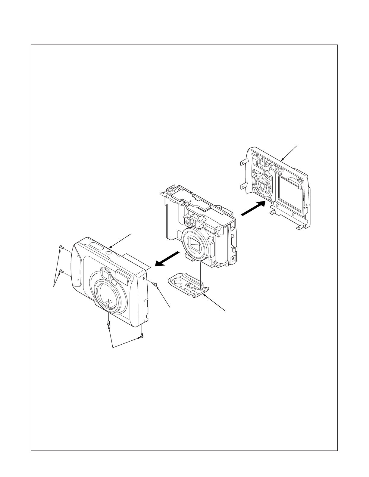
2-1. REMOVAL OF CABINET BACK AND CABINET FRONT
1. Five screws 1.7 x 4.5
2. Open the cover battery.
3. Cabinet back
4. Cabinet front
3
4
1
1
1
2
NOTE: Discharge a strobe capacitor
with the discharge jig (VJ8-0188) for
electric shock prevention.
– 10 –
Page 2
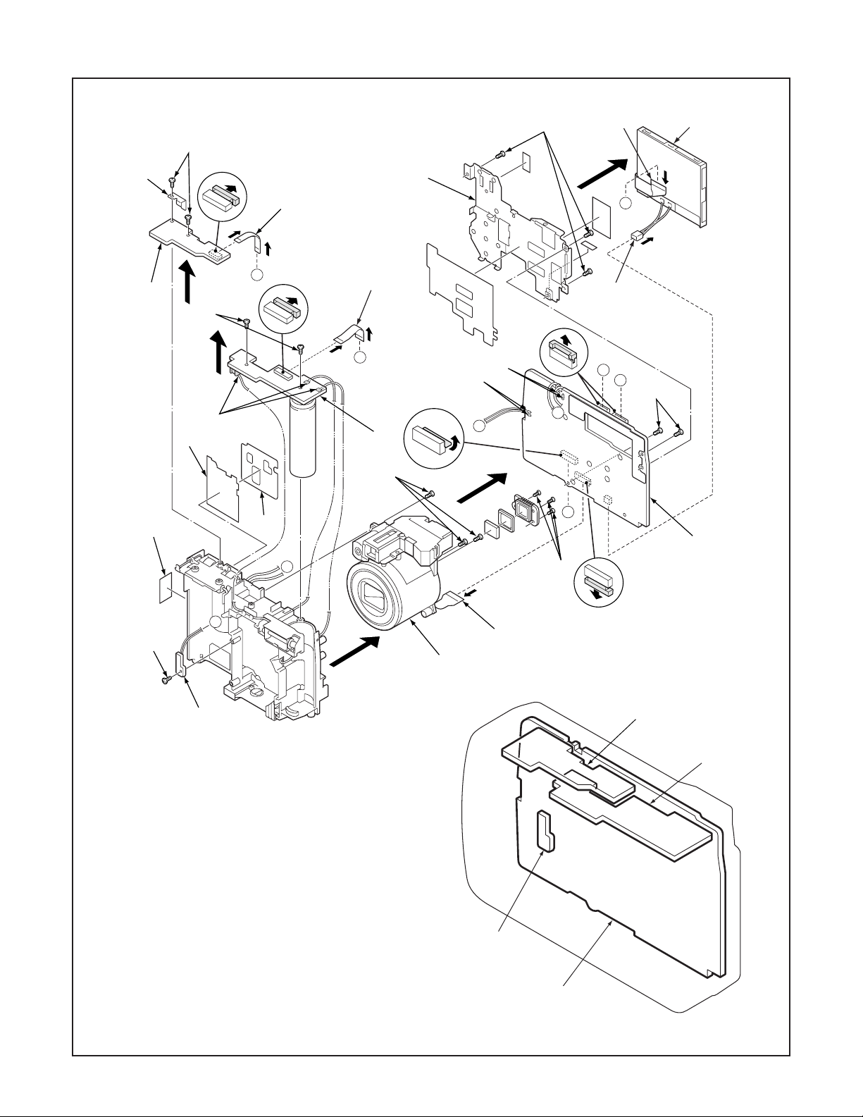
2-2. REMOVAL OF LCD, CP1 BOARD, TB1 BOARD, ST1 BOARD, LENS ASSEMBLY, TB2 BOARD AND BOARD LOCATION
16
17
11
15
24
18
19
4
1
3
5
7
D
8
C
10
12
E
2
D
C
6
A
20
B
21
23
E
14
A
13
B
25
26
1. FPC
2. Connector
3. LCD
4. Three screws 1.7 x 4
5. Holder monitor
6. Two screws 1.7 x 4
7. FPC
8. FPC
9. FPC
10. Remove the solder.
11. Spacer TB2
12. Remove the solder.
13. Three screws 1.6 x 3.5
14. CP1 board
15. Two screws 1.7 x 4
16. Earth plate
17. TB1 board
18. Two screws 1.7 x 4
19. Remove the solder.
20. ST1 board
21. Three screws 1.7 x 4
22. Lens assembly
23. Spacer fuse up
24. Spacer fuse
25. Screw 1.7 x 4
26. TB2 board
9
22
TB1 board
ST1 board
TB2 board
CP1 board
– 11 –
Page 3
3. ELECTRICAL ADJUSTMENT
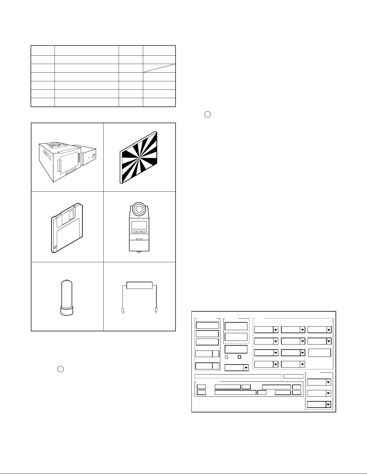
3-1. Table for Servicing Tools
1
1
1
1Chroma meter
1
1
Part code
VJ8-0190
VJ8-0237
VJ8-0192
VJ8-0191
VJ8-0188
Ref. No.
J-1
J-2
J-3
Name
Pattern box (color viewer)
Siemens star chart
Calibration software
Number
J-4
J-5
Spare lump
J-6
Discharge jig
Note: J-1 Pattern box (color viewer) is 100 - 110 VAC only.
J-1 J-2
J-3
J-4
6. LCD Panel Adjustment
6-1. LCD VcomPP Adjustment
6-2. LCD VcomDC Adjustment
Note: If the lens, CCD and board in item 2-5, it is necessary
to adjust again. Item 2-4 adjustments should be carried
out in sequence. Item 5 adjustment should be carried
out after item 3.
3-4. Setup
1. System requirements
Windows 98 or Me or 2000 or XP
IBM R -compatible PC with pentium processor
CD-ROM drive
3.5-inch high-density diskette drive
USB port
40 MB RAM
Hard disk drive with at least 15 MB available
VGA or SVGA monitor with at least 256-color display
2. Installing calibration software
1. Insert the calibration software installation diskette into your
diskette drive.
2. Open the explorer.
3. Copy the DscCalDI_140 folder on the floppy disk in the FD
drive to a folder on the hard disk.
J-5
J-6
3-2. Equipment
1. Oscilloscope
2. Digital voltmeter
3. AC adaptor
4. PC (IBM R -compatible PC, Pentium processor, Window
98 or Me or 2000 or XP)
3-3. Adjustment Items and Order
1. IC501 Oscillation Frequency Adjustment
2. Lens Adjustment
3. AWB Adjustment
4. CCD White Point Defect Detect Adjustment
5. CCD Black Point And White Point Defect Detect Adjust-
ment In Lighted
3. Installing USB driver
Install the USB driver with camera or connection kit for PC.
4. Pattern box (color viewer)
Turn on the switch and wait for 30 minutes for aging to take
place before using Color Pure. It is used after adjusting the
chroma meter (VJ8-0192) adjust color temperature to 3100 ±
20 K and luminosity to 900 ± 20 cd/m
2
. Be careful of handling
the lump and its circumference are high temperature during
use and after power off for a while.
5. Computer screen during adjustment
Calibration
AWB
Focus
UV Matrix
Cal Mode
Cal Data
USB storage
VID
Get
PID
Set
OK
OK
Upload
Firmware
Image
Initialize
EVF
LCD Type
LCD
R Bright
RGB Offset
Tint
VCO
H AFC Test
Serial
Set
Set
Rev.
B Bright
Gain
Phase
Set
Set
VCOMDC
VCOMPP
Hall Cal.
Setting
Language
Video Mode
Factory Code
– 12 –
Page 4

3-5. Connecting the camera to the computer
1. Line up the arrow on the cable connector with the notch on the camera's USB port. Insert the connector.
2. Locate a USB port on your computer.
To USB port
USB cable
AC adaptor
– 13 –
Page 5

3-6. Adjust Specifications
[CP1 board (Side B)]
VR501
CL541
CL401
CL402(GND)
Note:
1. Frequency adjustment is necessary to repair in the CP1
board and replace the parts.
2. Power voltage sets about +3.0 V.
Preparation:
1. Remove the cabinet back and holder monitor. You can see
VR501 and CL541 in the CP1 board.
Note: LCD flexible flat cable and backlight lead wire keep
connecting. When assembling, holder monitor and metal
part of LCD panel should not contact a substrate.
2. Insert the SD card.
3. Turn on the power switch, and set the camera mode.
1. IC501 Oscillation Frequency Adjustment
Measuring Point
Measuring Equipment
ADJ. Location
ADJ. Value
Adjustment method:
1. Adjust with VR501 to 501.3 ± 1 kHz.
CL541
Frequency counter
VR501
501.3 ± 1 kHz
2. Lens Adjustment
Camera
Preparation:
POWER switch: ON
Adjustment condition:
More than A3 size siemens star chart
Fluorescent light illumination with no flicker
Illumination above the subject should be 400 lux ± 10 %.
Adjustment method:
1. Set the siemens star chart 60 cm so that it becomes center
of the screen.
2. Connect the camera and the computer with USB cable.
3. Set the main switch to PC.
4. Select “OK”, and press the SET button.
5. Double-click on the DscCalDi.exe.
6. Click the Focus, and click the Yes.
7. Lens adjustment value will appear on the screen.
8. Click the OK.
DscCalDi
Approx.
60 cm 2 cm
Siemens
star chart
x
Focus Result
!
P(PRW)=80
P(BR)=18
FOCUS=4,2,-2,-6
OK
Adjustment value determination is effectuated using the
"P(PRW)", “P(BR)” and "FOCUS" values.
If FOCUS=f1, f2, f3, f4 and the adjustment values fulfill the
conditions below, they are determined as within specifications.
Adjustment value determination
67<=prw<=135
pbr<=40
-70<=f1<=68
-100<=f2<=100
-104<=f3<=136
-111<=f4<=183
– 14 –
Page 6

3. AWB Adjustment
Camera
Pattern box
(color viewer)
Preparation:
POWER switch: ON
Adjusting method:
1. When setting the camera in place, set it to an angle so that
nothing appears in any part of the color viewer except the
white section. (Do not enter any light.)
2. Double-click on the DscCalDi.exe.
3. Click the AWB, and click the Yes.
4. AWB adjustment value will appear on the screen.
5. Click the OK.
Dsc Calibration
AWB Result:
1:
AGC=220,388,481,724,892
3F_AGC=0,0
WB=237,511,501
CHECK=128,128,140
MS=3472,3565
0
IRIS=179
x
OK
Copy
4. CCD White Point Defect Detect Adjustment
Preparation:
POWER switch: ON
Adjustment method:
1. Double-click on the DscCalDi.exe.
2. Select “CCD Defect” on the LCD “Test”, and click the “Ye s ”.
3. After the adjustment is completed, OK will display.
4. Click the OK.
5. CCD Black Point And White Point Defect Detect
Adjustment In Lighted
Camera
Pattern box
(color viewer)
Preparation:
POWER switch: ON
Setting of pattern box:
Color temperature: 3100 ± 20 (K)
Luminance: 900 ± 20 (cd/m
Adjusting method:
1. Set the camera 0 cm from the pattern box. (Do not enter
any light.)
2. Double-click on the DscCalDi.exe.
3. Select “CCD Black” on the LCD “Test”, and click the “Ye s ”.
4. After the adjustment is completed, the number of defect
will appear.
2
)
Adjustment value determination is effectuated using the "AGC",
“CHECK" and "MS" values.
If AGC=a1, a2, a3, a4, a5, CHECK=wc0, wc1, wc2 and
MS=MS1, MS2, the adjustment values fulfill the conditions be-
low, they are determined as within specifications.
Adjustment value determination
150<a1<350, 330<a2<540, 450<a3<680,
600<a4<850, 800<a5<1024
wc0=128 ± 2, wc1=128 ± 2, wc2=130 ± 40
2500<=MS1<=4500
2900<=MS2<=5200
150<IRIS<220
Adjustment values other than the above are irrelevant.
– 15 –
Page 7

6. LCD Panel Adjustment
Firmware
Image
AWB
Focus
UV Matrix
R Bright
RGB Offset
Tint
B Bright
Gain
Phase
LCD
Calibration
Upload
Initialize
LCD Type
H AFC Test
VCOMDC
VCOMPP
Cal Data
Cal Mode
OK
OK
EVF
USB storage
Get
Set
VID
Set
PID
Set
Serial
Set
Rev.
Set
Setting
Language
Video Mode
VCO
Factory Code
Hall Cal.
[CP1 board (Side B)]
VR501
CL541
CL401
CL402(GND)
6-1. LCD VcomPP Adjustment
Preparation:
POWER switch: ON
Adjusting method:
1. Double-click on the DscCalDi.exe.
2. Adjust LCD “VCOMPP” so that the amplitude of the CL401
waveform is 5.60 V ± 0.05 Vp-p.
3-7. Factory Code Setting
1. Check the "Factory Code" display within the Setting group.
2. For U.S.A., Canada and NTSC general area
If "FC_SANYO_U" does not appear, click on the " " mark
located on the right of the "Factory Code" display BOX and
select "FC_SANYO_U".
3. For Europe and PAL general area
If "FC_SANYO_EX" does not appear, click on the " " mark
located on the right of the "Factory Code" display BOX and
select "FC_SANYO_EX".
3-8. Language Setting
1. Click on the " " mark located on the right of the
"Language" display BOX.
2. Select language. (Default is English.)
3. End "DscCal" and remove the camera before turning the
camera power OFF.
5.60 V
± 0.05 Vp-p
CL401 waveform
6-2. LCD VcomDC Adjustment
Adjusting method:
1. Adjust LCD “VCOMDC” so that the amplitude of the CL401
waveform is 4.10 V ± 0.05 Vp-p.
4.10 V
± 0.05 Vp-p
CL401 waveform
GND
(CL402)
– 16 –
Page 8

4. USB STORAGE INFORMATION
REGISTRATION
USB storage data is important for when the camera is connected to a computer via a USB connection.
If there are any errors in the USB storage data, or if it has not
been saved, the USB specification conditions will not be satisfied, so always check and save the USB storage data.
Preparation:
POWER switch: ON
Adjustment method:
1. Connect the camera to a computer. (Refer to 3-5. Connecting the camera to the computer on the page 13.)
2. Double-click on the DscCalDi.exe.
3. Click on the Get button in the USB storage window and
check the USB storage data.
VID: SANYO
PID: S4
Serial:
Rev. : 1.00
4. Check the “Serial” in the above USB storage data. If the
displayed value is different from the serial number printed
on the base of the camera, enter the number on the base
of the camera. Then click the Set button.
5. Next, check VID, PID and Rev. entries in the USB storage
data. If any of them are different from the values in 3. above,
make the changes and then click the corresponding Set
button.
Calibration
AWB
Focus
UV Matrix
Cal Mode
Cal Data
USB storage
VID
Get
PID
Set
OK
OK
Upload
Firmware
Image
Initialize
EVF
LCD Type
LCD
R Bright
RGB Offset
Tint
VCO
H AFC Test
Serial
Set
Set
Rev.
B Bright
Gain
Phase
Set
Set
VCOMDC
VCOMPP
Hall Cal.
Setting
Language
Video Mode
Factory Code
– 17 –
 Loading...