

Page 1
3. ELECTRICAL ADJUSTMENT
Firmware
Image
AWB
Focus
UV Matrix
RGB Odd
RGB Gain
Tint
RGB Even
VCOMDC
Phase
LCD
Calibration
Upload
Initialize
LCD Type
H AFC Test
VCOMPP(LOW)
VCOMPP(HI)
Cal Data
Cal Mode
OK
OK
EVF
USB storage
Get
Set
VID
Set
PID
Set
Serial
Set
Rev.
Set
Setting
Language
Video Mode
VCO
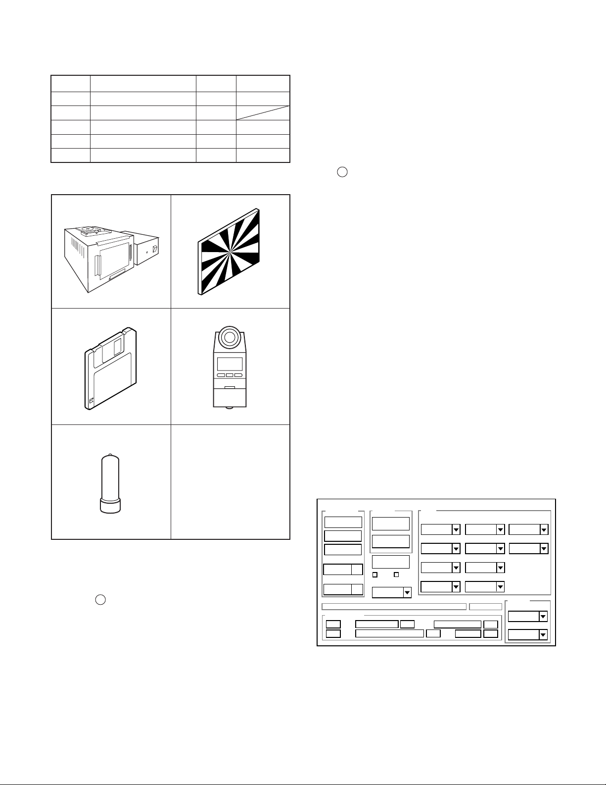
3-1. Table for Servicing Tools
1
1
1
1Chroma meter
1
Part code
VJ8-0190
VJ8-0193
VJ8-0192
VJ8-0191
Ref. No.
J-1
J-2
J-3
Name
Pattern box (color viewer)
Siemens star chart
Calibration software
Number
J-4
J-5
Spare lump
Note: J-1 Pattern box (color viewer) is 100 - 110 VAC only.
J-1 J-2
J-3
J-4
Note: If the lens, CCD and board in item 2-6, it is necessary
to adjust again. Item 2-6 adjustments other than these
should be carried out in sequence. For 5 and 6, carry
out adjustment after sufficient charging has taken place.
In case of carrying out adjustment item 3 and 4 after
adjusting item 5 and 6, adjust item 3 and 4 after turing
off the power.
3-4. Setup
1. System requirements
Windows 98 or Me or 2000 or XP
IBM R -compatible PC with pentium processor
CD-ROM drive
3.5-inch high-density diskette drive
USB port
40 MB RAM
Hard disk drive with at least 15 MB available
VGA or SVGA monitor with at least 256-color display
2. Installing calibration software
1. Insert the calibration software installation diskette into your
diskette drive.
2. Open the explorer.
3. Copy the DscCalDI_129 folder on the floppy disk in the FD
drive to a folder on the hard disk.
J-5
3-2. Equipment
1. Oscilloscope
2. Digital voltmeter
3. AC adaptor
4. PC (IBM R -compatible PC, Pentium processor, Window
98 or Me or 2000 or XP)
3-3. Adjustment Items and Order
1. IC501 Oscillation Frequency Adjustment
2. CCD VSUB Adjustment
3. AWB Adjustment
4. Lens Adjustment
5. CCD Defect Detect Adjustment
6. CCD Black Point Defect Detect Adjustment
7. LCD Panel Adjustment
7-1. LCD RGB Offset Adjustment
7-2. LCD Gain Adjustment
3. Installing USB driver
Install the USB driver with camera or connection kit for PC.
4. Pattern box (color viewer)
Turn on the switch and wait for 30 minutes for aging to take
place before using Color Pure. It is used after adjusting the
chroma meter (VJ8-0192) adjust color temperature to 3100 ±
20 K and luminosity to 900 ± 20 cd/m
2
. Be careful of handling
the lump and its circumference are high temperature during
use and after power off for a while.
5. Computer screen during adjustment
– 12 –
Page 2
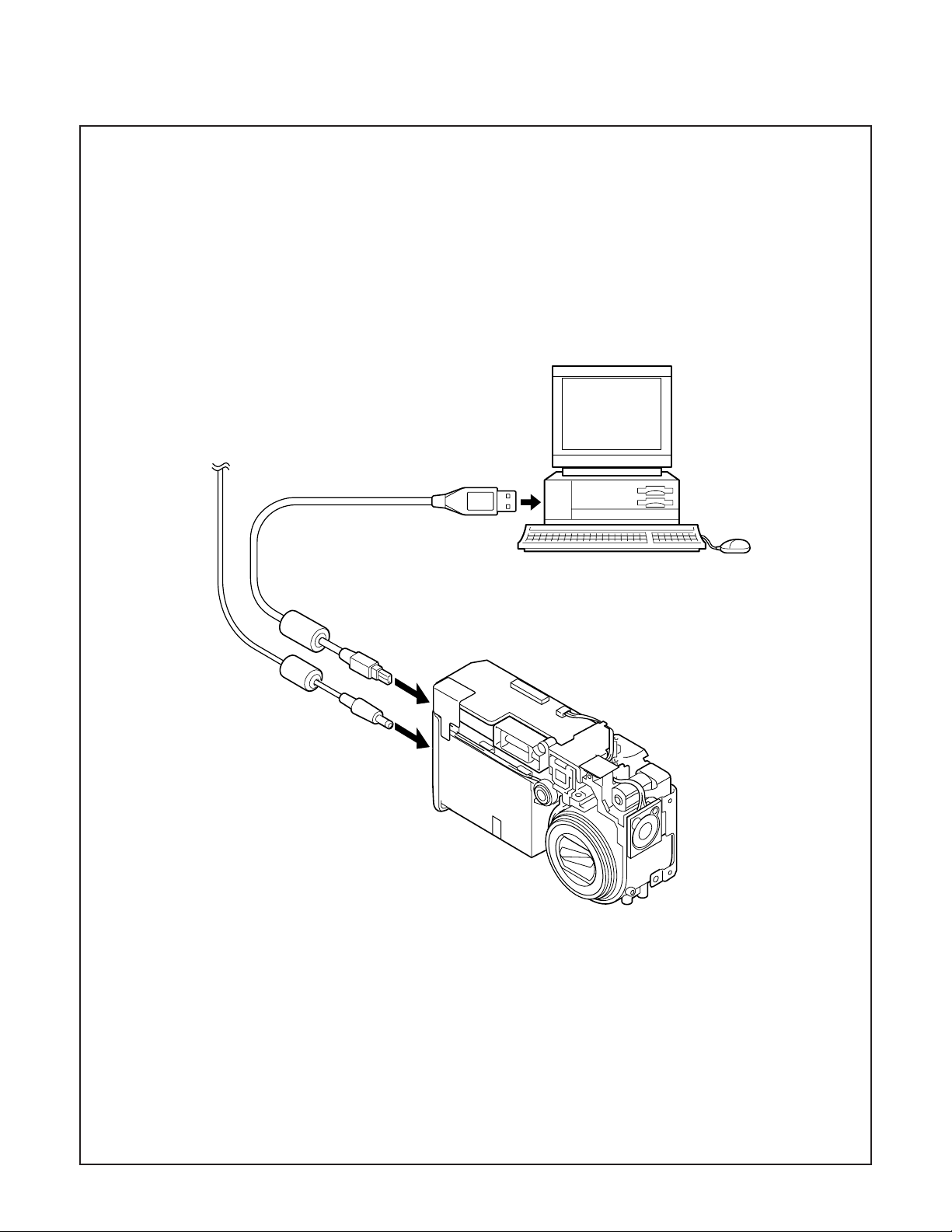
3-5. Connecting the camera to the computer
1. Line up the arrow on the cable connector with the notch on the camera's USB port. Insert the connector.
2. Locate a USB port on your computer.
To USB port
AC adaptor
USB cable
– 13 –
Page 3
3-6. Adjust Specifications
[PW1 board (Side B)]
CL526
VR501
Note:
1. When installing a new CCD, read the abbreviation described
on the rear side of CCD, and write it to the board.
2. If the CCD, each board and parts replaces, it is necessary
to adjust again.
Adjustment method:
1. Turn on the power. (Insert the DC jack.)
2. Shorten TP301 and TP302 of SY1 board with pushing S3003
(Flash sw).
3. Read the abbreviation display on the rear side of CCD.
Convert these to voltages using the table below.
For example, “h” → VSUB = 11.7 V
4. Adjust with VR921 so that the voltage of TP901 at VSUB
becomes the displayed voltage value ± 0.1 V.
Note:
1. Frequency adjustment is necessary to repair in the PW1
board and replace the parts. It is carried out with LCD
through screen display mode.
Preparation:
1. Carry out the frequency adjustment disconnecting cabinet
front, cabinet back, cabinet top and screws of holder battery. Side B of PW1 board can be seen.
2. Connect FPC of cabinet back to CN303.
3. Insert the compact flash.
4. Set the main switch to the camera mode.
5. Set the selector dial to the still image shooting mode.
6. Push the power switch, and comfirm that the through screen
from the CCD can be seen on the LCD.
1. IC501 Oscillation Frequency Adjustment
Measuring Point
Measuring Equipment
ADJ. Location
ADJ. Value
Adjustment method:
1. Adjust with VR501 to 496 ± 1 kHz.
CL526
Frequency counter
VR501
496 ± 1 kHz
VSUB abbreviation
Voltage
C
10.7
N
12.7
1
8.9
D
10.9E11.1
P
12.9
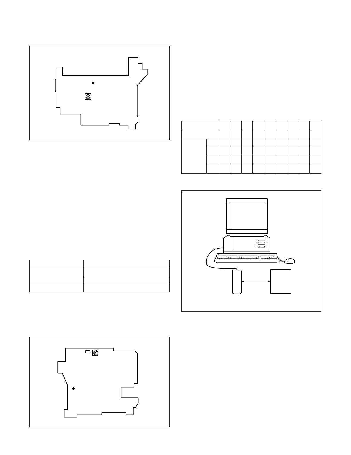
3. AWB Adjustment
Camera
2
9.139.349.5
f
11.5
11.3
R
S
13.5
13.3
13.1
0~18 cm
6
9.779.9810.1
G
H
11.7
U
V
13.7
Pattern box
(color viewer)
J
11.9
W
13.9
K
12.1
X
14.1
9
10.3
L
12.3
Y
14.3
A
10.5
m
12.5
Z
14.5
2. CCD VSUB Adjustment
[CA2 board (Side A)]
TP901
CL136(G)
VR501
Preparation:
POWER switch: ON
Adjusting method:
1. When setting the camera in place, set it to an angle so that
nothing appears in any part of the color viewer except the
white section. (Do not enter any light.)
2. Double-click on the DscCalDi129.
3. Click the AWB, and click the Yes.
4. AWB adjustment value will appear on the screen.
5. Click the OK.
– 14 –
Page 4

4. Lens Adjustment
6. CCD Black Point Defect Detect Adjustment
Camera
Siemens
star chart
Preparation:
POWER switch: ON
Adjustment condition:
More than A3 size siemens star chart
Fluorescent light illumination with no flicker
Illumination above the subject should be 400 lux ± 10 %.
Adjustment method:
1. Set the siemens star chart 100 cm ± 3 cm so that it becomes center of the screen.
2. Double-click on the DscCalDi129.
3. Click the Focus, and click the Yes.
4. Lens adjustment value will appear on the screen.
5. Click the OK.
5. CCD Defect Detect Adjustment
Preparation:
POWER switch: ON (Set the camera mode.)
Adjustment method:
1. Double-click on the DscCalDi129.
2. Select “CCD Defect” on the LCD “Test”, and click the “Ye s ”.
3. After the adjustment is completed, OK will display.
4. Click the OK.
Camera
0~18 cm
Pattern box
(color viewer)
Preparation:
POWER switch: ON
Adjusting method:
1. When setting the camera in place, set it to an angle so that
nothing appears in any part of the color viewer except the
white section. (Do not enter any light.)
2. Double-click on the DscCalDi129.
3. Select “CCD Black” on the LCD “Test”, and click the “Ye s ”.
4. After the adjustment is completed, the number of defect will
appear.
7. LCD Panel Adjustment
[CA2 board (Side A)]
TP901
VR501
CL136(G)
7-1. LCD RGB Offset Adjustment
Preparation:
POWER switch: ON
Adjusting method:
1. Double-click on the DscCalDi129.
2. Adjust LCD “RGB Odd” so that the amplitude of the CL136
waveform is 0.95 V ± 0.05 V.
3. Adjust LCD “RGB Even” so that the amplitude of the CL136
waveform is 4.55 V ± 0.05 V.
– 15 –
Page 5

4.55 ±
0.05 V
0.95 ± 0.05 V
CL136 waveform
7-2. LCD Gain Adjustment
Adjusting method:
1. Adjust LCD “RGB Gain” so that the amplitude of the CL136
waveform is 1.55 V ± 0.1 Vp-p.
Note:
7-1. LCD RGB Offset adjustment should always be carried
out first.
1.55 V
± 0.1 Vp-p
CL136 waveform
– 16 –
Page 6

4. USB STORAGE INFORMATION
REGISTRATION
USB storage data is important for when the camera is connected to a computer via a USB connection.
If there are any errors in the USB storage data, or if it has not
been saved, the USB specification conditions will not be satisfied, so always check and save the USB storage data.
Preparation:
POWER switch: ON
Adjustment method:
1. Connect the camera to a computer. (Refer to 3-5. Connecting the camera to the computer on the page 13.)
2. Double-click on the DscCalDi129.
3. Click on the Get button in the USB storage window and
check the USB storage data.
VID: SANYO
PID: VPC-MZ3 or VPC-MZ3EX
Serial:
Rev. : 1.00
4. Check the “Serial” in the above USB storage data. If the
displayed value is different from the serial number printed
on the base of the camera, enter the number on the base
of the camera. Then click the Set button.
5. Next, check VID, PID and Rev. entries in the USB storage
data. If any of them are different from the values in 3. above,
make the changes and then click the corresponding Set
button.
Calibration
AWB
Focus
UV Matrix
Cal Mode
Cal Data
USB storage
VID
Get
PID
Set
OK
OK
Upload
Firmware
Image
Initialize
EVF
LCD Type
LCD
RGB Odd
RGB Gain
Tint
VCO
H AFC Test
Serial
Set
Set
Rev.
RGB Even
VCOMDC
Phase
Set
Set
VCOMPP(LOW)
VCOMPP(HI)
Setting
Language
Video Mode
– 17 –
Page 7

5. TROUBLESHOOTING GUIDE
POWER LOSS INOPERTIVE
PUSH MAIN SW
IC301-45 (SCAN IN 6)
PULSE INPUT
YES
IC302-7 4.7 V
(BOOST 4.7 V)
HIGH
IC301-10
(VDD)
HIGH
IC301-36
(RESET)
HIGH
IC301-43
(BAT OFF)
HIGH
IC301-40
OSCILLATION
YES
IC301-37
OSCILLATION
YES
NO
CHECK CN303-3
LOW
CHECK PW1, IC952
LOW
LOW
LOW
NO
NO
CHECK IC302
CHECK IC302, R3004
CHECK R3003
CHECK X3001
CHECK X3002
TAKING INOPERATIVE
PUSH SHUTTER
BUTTON
IC301-55, 45
(SCAN IN 5, 6)
PULSE INPUT
YES
CN301-18, 15
(P ON, P(A) ON)
HIGH
SERIAL
COMMUNICATION
OK
CHECK CA2
NO
LOW
NG
CHECK S3001,
D3012, D3013,
R3038, R3037
CHECK IC301,
RB302, PW1
CHECK
IC301, CA2
CHECK IC301
NO PICTURE
CHECK CLK
OSCILLATION X1101,
IC111, R1101
YES
SD CLK
OSCILLATION
R1103
OK
IC102-62, 63
IC301-15, 16
OK
CHECK SOLDERING
OF MEMORY PIN
MAIN CLOCK FOR SYSTEM OPERATION
NO
NO OPERATION IF ABSENT
CHECK X1101 OSCILLATOR, R1101 AND IC111
SD RAM (IC103) MOVEMENT CLOCK
NG
NO READ PROGRAM FROM IC121 IF ABSENT
CHECK IC102, IC103
INCORRECT HAND
NG
SHAKING 8-BIT CPU
CHECK EACH INTERFACE
– 18 –
 Loading...