

Page 1
3. ELECTRICAL ADJUSTMENT
Firmware
Image
AWB
Focus
UV Matrix
R Bright
RGB Offset
Tint
B Bright
Gain
Phase
LCD
Calibration
Upload
Initialize
LCD Type
H AFC Test
VCOMDC
VCOMPP
Cal Data
Cal Mode
OK
OK
EVF
USB storage
Get
Set
VID
Set
PID
Set
Serial
Set
Rev.
Set
Setting
Language
Video Mode
VCO
Factory Code
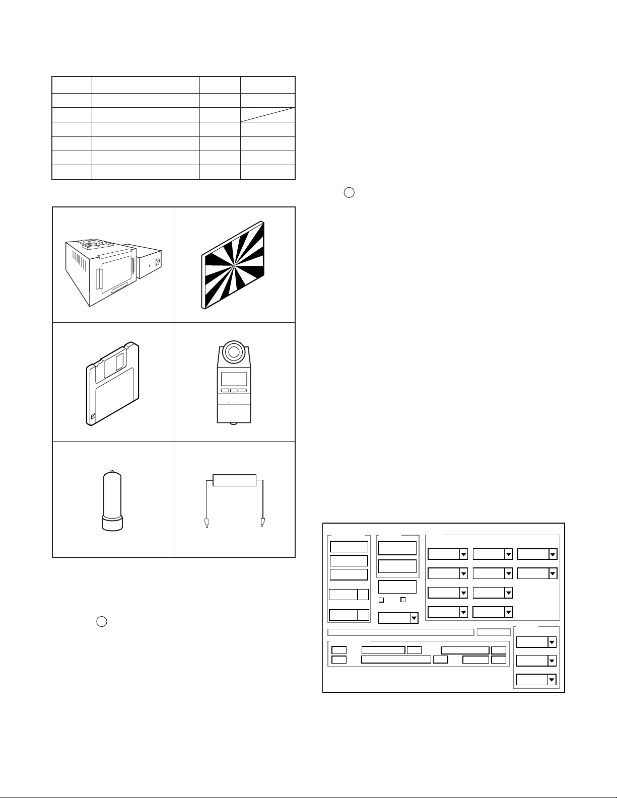
3-1. Table for Servicing Tools
1
1
1
1Chroma meter
1
1
Part code
VJ8-0190
VJ8-0237
VJ8-0192
VJ8-0191
VJ8-0188
Ref. No.
J-1
J-2
J-3
Name
Pattern box (color viewer)
Siemens star chart
Calibration software
Number
J-4
J-5
Spare lump
J-6
Discharge jig
Note: J-1 Pattern box (color viewer) is 100 - 110 VAC only.
J-1 J-2
J-3
J-4
6. LCD Panel Adjustment
6-1. LCD VcomPP Adjustment
6-2. LCD VcomDC Adjustment
Note: If the lens, CCD and board in item 2-5, it is necessary
to adjust again. Item 2-4 adjustments should be carried
out in sequence. Item 5 adjustment should be carried
out after item 3.
3-4. Setup
1. System requirements
Windows 98 or Me or 2000 or XP
IBM R -compatible PC with pentium processor
CD-ROM drive
3.5-inch high-density diskette drive
USB port
40 MB RAM
Hard disk drive with at least 15 MB available
VGA or SVGA monitor with at least 256-color display
2. Installing calibration software
1. Insert the calibration software installation diskette into your
diskette drive.
2. Open the explorer.
3. Copy the DscCalDI_140 folder on the floppy disk in the FD
drive to a folder on the hard disk.
J-5
J-6
3-2. Equipment
1. Oscilloscope
2. Digital voltmeter
3. AC adaptor
4. PC (IBM R -compatible PC, Pentium processor, Window
98 or Me or 2000 or XP)
3-3. Adjustment Items and Order
1. IC501 Oscillation Frequency Adjustment
2. Lens Adjustment
3. AWB Adjustment
4. CCD White Point Defect Detect Adjustment
5. CCD Black Point And White Point Defect Detect Adjust-
ment In Lighted
3. Installing USB driver
Install the USB driver with camera or connection kit for PC.
4. Pattern box (color viewer)
Turn on the switch and wait for 30 minutes for aging to take
place before using Color Pure. It is used after adjusting the
chroma meter (VJ8-0192) adjust color temperature to 3100 ±
20 K and luminosity to 900 ± 20 cd/m
2
. Be careful of handling
the lump and its circumference are high temperature during
use and after power off for a while.
5. Computer screen during adjustment
– 12 –
Page 2
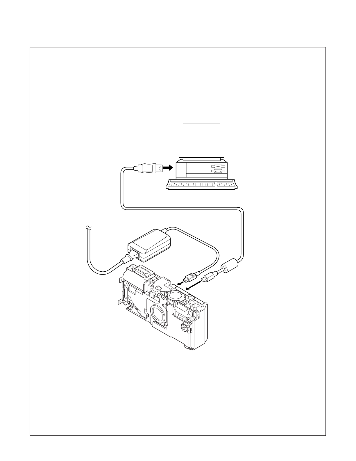
3-5. Connecting the camera to the computer
1. Line up the arrow on the cable connector with the notch on the camera's USB port. Insert the connector.
2. Locate a USB port on your computer.
To USB port
AC adaptor
USB cable
– 13 –
Page 3

3-6. Adjust Specifications
[ST1 board (Side A)]
CL518
2. Lens Adjustment
VR501
Backlight
lead wire
TB1 board
power
lead wire
ST1 board
CN501
CP1 board
CP1-ST1
connector
Note:
1. Frequency adjustment is necessary to repair in the ST1
board and replace the parts. It is carried out with play mode.
Preparation:
1. Discharge a strobe capacitor in the ST1 board.
2. Connect the connector in the CP1 board and CN501 in the
ST1 board. Connect backlight lead wire to CN172 in the
CP1 board. (Refer to above picture.)
3. Set the main switch to playback mode in the CP1 board.
4. Input DC power from TB1 board.
5. Carry out assembling the camera after adjusting the
oscillation frequency .
1. IC501 Oscillation Frequency Adjustment
Measuring Point
Measuring Equipment
ADJ. Location
ADJ. Value
CL518
Frequency counter
VR501
496.5 ± 1 kHz
Camera
Approx.
150 cm 3 cm
Siemens
star chart
Preparation:
POWER switch: ON
Adjustment condition:
More than A3 size siemens star chart
Fluorescent light illumination with no flicker
Illumination above the subject should be 400 lux ± 10 %.
Adjustment method:
1. Set the siemens star chart 150 cm ± 3 cm so that it becomes center of the screen.
2. Connect the camera and the computer with USB cable.
3. Select “CARD READER”, and push the SET button.
4. Double-click on the DscCalDi.exe.
5. Click the Focus, and click the Yes.
6. Lens adjustment value will appear on the screen.
7. Click the OK.
DscCalDi
x
Focus Result
!
STD_AFPOS=1033
FOCUS=3,-36,0,0
OK
Adjustment value determination is effectuated using the "STD
AFPOS" and "FOCUS" values.
If FOCUS=focus1, focus2 and the adjustment values fulfill the
conditions below, they are determined as within specifications.
Adjustment value determination
985<=STD_AFPOS<=1055
-20<=focus1<=+15
-80<focus2<0
Adjustment method:
1. Adjust with VR501 to 496.5 ± 1 kHz.
– 14 –
Page 4

3. AWB Adjustment
Camera
Pattern box
(color viewer)
Preparation:
POWER switch: ON
Adjusting method:
1. When setting the camera in place, set it to an angle so that
nothing appears in any part of the color viewer except the
white section. (Do not enter any light.)
2. Double-click on the DscCalDi.exe.
3. Click the AWB, and click the Yes.
4. AWB adjustment value will appear on the screen.
5. Click the OK.
Dsc Calibration
AWB Result:
1:
AGC=190,357,524,692,860
3F_AGC=1,1
WB=318,513,716
CHECK=126,128,143
MS=3912,4296
0
IRIS=0
x
OK
Copy
4. CCD White Point Defect Detect Adjustment
Preparation:
POWER switch: ON
Adjustment method:
1. Double-click on the DscCalDi.exe.
2. Select “CCD Defect” on the LCD “Test”, and click the “Ye s ”.
3. After the adjustment is completed, OK will display.
4. Click the OK.
5. CCD Black Point And White Point Defect Detect
Adjustment In Lighted
Camera
Pattern box
(color viewer)
Preparation:
POWER switch: ON
Setting of pattern box:
Color temperature: 3100 ± 20 (K)
Luminance: 900 ± 20 (cd/m
Adjusting method:
1. Set the camera 0 cm from the pattern box. (Do not enter
any light.)
2. Double-click on the DscCalDi.exe.
3. Select “CCD Black” on the LCD “Test”, and click the “Ye s ”.
4. After the adjustment is completed, the number of defect
will appear.
2
)
Adjustment value determination is effectuated using the "AGC",
“CHECK" and "MS" values.
If AGC=a1, a2, a3, a4, a5, CHECK=wc0, wc1, wc2 and
MS=MS1, MS2, the adjustment values fulfill the conditions be-
low, they are determined as within specifications.
Adjustment value determination
a1<1023, a2<1023, a3<1023, a4<1023, a5<1023
wc0=128 ± 2, wc1=128 ± 2, wc2=130 ± 40
3400<=MS1<=4850
3800<=MS2<=5250
Adjustment values other than the above are irrelevant.
– 15 –
Page 5

6. LCD Panel Adjustment
[CP1 board (Side A)]
CL404
3-7. Factory Code Setting
1. Check the "Factory Code" display within the Setting group.
2. For models VPC-J4
If "FC_SANYO_U" does not appear, click on the " " mark
located on the right of the "Factory Code" display BOX and
select "FC_SANYO_U".
3. For models VPC-J4EX, VPC-J4EXBK or VPC-J4EXOR
If "FC_SANYO_EX" does not appear, click on the " " mark
located on the right of the "Factory Code" display BOX and
select "FC_SANYO_EX".
4. End "DscCal" and remove the camera before turning the
camera power OFF.
6-1. LCD VcomPP Adjustment
Preparation:
POWER switch: ON
Adjusting method:
1. Double-click on the DscCalDi.exe.
2. Adjust LCD “VCOMPP” so that the amplitude of the CL404
waveform is 5.60 V ± 0.05 Vp-p.
5.60 V
± 0.05 Vp-p
CL404 waveform
Calibration
AWB
Focus
UV Matrix
Cal Mode
Cal Data
USB storage
VID
Get
PID
Set
OK
OK
Upload
Firmware
Image
Initialize
EVF
LCD Type
LCD
R Bright
RGB Offset
Tint
VCO
H AFC Test
Serial
Set
Set
Rev.
B Bright
Gain
Phase
Set
Set
VCOMDC
VCOMPP
Setting
Language
Video Mode
Factory Code
6-2. LCD VcomDC Adjustment
Adjusting method:
1. Adjust LCD “VCOMDC” so that the amplitude of the CL404
waveform is 4.15 V ± 0.05 Vp-p.
4.15 V
± 0.05 Vp-p
GND
CL404 waveform
– 16 –
 Loading...