

Page 1
INSTRUCTION MANUAL
(
)
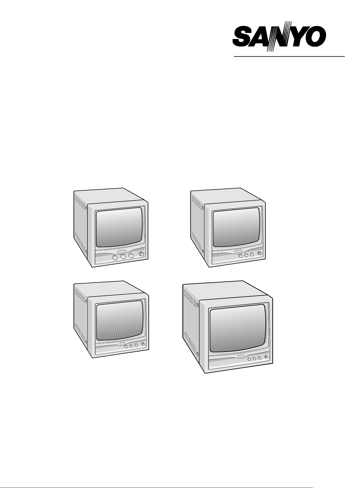
VM-6609P
VM-6612P
VM-6615P
B/W Video Monitor
6609P (9 inch) 6612P (12 inch)
VM-6620P
6615P (15 inch)
6620P
About this manual
Before installing and using this unit, please read this manual carefully. Be sure to keep it handy for later reference.
•
This manual gives basic connections and operating instructions for 4 models (VM-6609P, 6612P, 6615P and 6620P).
•
20 inch
Page 2

PRECAUTION
WARNING: TO REDUCE THE RISK OF FIRE OR
ELECTRIC SHOCK, DO NOT EXPOSE THIS
APPLIANCE TO RAIN OR OTHER MOISTURE.
To avoid electrical shock, do not open the cabinet.
Refer servicing to qualified personnel only.
If the power supply cord (AC power cord) of this
appliance is damaged, it must be replaced. Return to a
SANYO Authorised Service Centre for replacement of
the cord.
If an abnormality does occur, turn the power switch off and
unplug the unit. Have a qualified technician perform any
repairs.
Do not use the monitor if it makes a strange noise, emits a
strange odor, or if smoke comes out from it
If used under these conditions, the monitor may cause a fire or
electric shock. Immediately unplug it and wait to make sure no
more smoke comes from it. Then take it to the dealer for service.
Do not try to repair or open the monitor yourself.
Do not allow the power cord to get damaged
Do not place heavy objects on the power cord.
•
Do not place the power cord near a heat source.
•
Do not excessively bend the power cord, modify it, or secure
•
it with staples.
Doing so may damage the power cord and cause a fire or
electric shock.
If the power cord is damaged, take it to the dealer and have it
replaced.
Do not allow dust or dirt to build up on the
power cord or power outlet
A build-up of dust may cause a short circuit or generate heat
and cause a fire.
Be especially careful when using the monitor in areas of high
humidity, in areas with frequent condensation, in kitchens, and in
places where there is excessive dust.
Periodically unplug the power cord and clean away the dust that
builds up between the plug terminals.
Cautions when plugging in the power cord
Make sure you insert the plug of the power cord all the way in
•
the power outlet. Using the monitor with the power cord not
fully plugged in may cause heat to generate and cause a fire.
Do not use the monitor with the power cord wound or tied up.
•
Heat may generate and cause a fire.
When using an extension cord, be sure that the total current load
•
of all equipment connected to it dose not exceed the specified
ratings of the extension cord. If the rating are exceeded, heat may
generate and cause a fire. Make sure to carefully read the
specifications accompanying the extension cord.
Do not modify or open the cabinet
Never touch the inside of the monitor. High voltage circuits are
inside, and there is a high risk of fire or electric shock if they are
touched. Any internal checks, settings, or repairs should be
performed by the dealer.
Do not place object containing liquids (flower
vase, etc.) on top of the monitor.
If water or any other liquid does get inside the monitor,
immediately turn it off and unplug it.
Do not get the monitor wet
Do not allow the monitor to get wet or allow water or other
•
liquids inside it. Doing so may cause a fire or electric shock.
Be especially careful during rainy weather, snowy weather,
near the beach, or near bodies of water.
Do not use the monitor in a bathroom.
•
Do not use the monitor during a lightning
Do not touch it or its power cord during a lightning. Doing so
may cause an electric shock.
Do not place the monitor on an unstable surface
It may fall, causing damage or personal injury. If it falls and its
body is damage, immediately turn it off and unplug.
Never pull on the cord to unplug the power cord
Always unplug the power cord by holding the power plug and
•
slowly pulling out.
Pulling at the cord may damage the power cord and cause a fire
or electric shock.
Do not touch the power cord or plug with wet hands. Doing so
•
may cause an electric shock.
Cautions regarding the location where the
monitor is used.
Do not place it in locations with excessive humidity or dust, or
•
location subjected to oily vapors or steam.
Do not place it in locations subject to direct sunlight or near
•
heat generating equipment. Doing so may cause an accident
property damage.
Do not cover the air vents
Do not place the monitor in a poorly ventilated location. Do not
block its air vents by covering it with a cloth, placing it on a
carpet or blanket, or other means. If the air vents are blocked,
the internal temperature will rise and it may cause a fire.
Cleaning
Dirt can be removed from the cabinet by wiping it with a soft
•
cloth. To remove stains, wipe with a soft cloth moistened with
a soft detergent solution and wrung dry, then wipe dry with
bry soft cloth.
Do not use benzine, thinner or other chemical product on the
•
cabinet, as that may cause deformation and paint peeling.
Before using a chemical cloth, make sure to read all
accompanying instructions. Make sure that no plastic or
rubber material comes in contact with the cabinet for a long
period of time, as that may cause damage or paint peeling.
SERVICE
This unit is a precision instruments and if treated with care, will
provide years of satisfactory performance. However, in the event
of a problem, the owner is advised not to attempt to make
repairs or open the cabinet. Servicing should always be referred
to your dealer or Sanyo Authorized Service Centre.
Do not place object inside the monitor
Do not insert any metallic object through the ventilation grills.
•
Do not stick metal objects (paper clips, hair pins, etc.), paper,
•
matches, etc., inside the monitor.
1
Page 3

CONTENTS
FEATURES
PARTS NAMES . . . . . . . . . . . . . . . . . . . . . . . . 3
Front Panel . . . . . . . . . . . . . . . . . . . . . . . . 3
Rear Panel . . . . . . . . . . . . . . . . . . . . . . . . . 3
CONNECTION . . . . . . . . . . . . . . . . . . . . . . . . . 4
Single connection . . . . . . . . . . . . . . . . . . . 4
Multiple connection . . . . . . . . . . . . . . . . . 5
BASIC OPERATION . . . . . . . . . . . . . . . . . . . . 5
TROUBLESHOOTING . . . . . . . . . . . . . . . . . . . 5
SPECIFICATIONS . . . . . . . . . . . . . . . . . . . . . . 6
Universal power (AC 100V to AC 240V) and
•
detachable power cord
2 Channel Input - A/B Channel selectable
•
Contrast, Bright control on front panel and
•
Sub-bright, V-size, V-hold control on rear panel
Horizontal resolution
•
VM-6609P, 6612P: more than 800 TV line
VM-6615P, 6620P: more than 1000 TV line
Important (U. K. only)
Connect the mains lead to a suitable plug following the
colour code:
Blue wire (Neutral) → to plug pin N or coloured black
•
Brown wire (Live) → to plug pin L or coloured red
•
Green and Yellow wire (Earth) → to plug pin E or “%”
•
Do not connect Blue and Brown wire onto plug pin E or onto
earth symbol “%”.
2
Page 4

PARTS NAMES
Front Panel
1
Monitor Selector Switch (VIDEO A/B)
Turn this Monitor selector switch A position for a signal fed
through the rear panel VIDEO A connectors.
Then, turn this Monitor selector switch B position for a signal
fed through the rear panel VIDEO B connectors.
2Contrast Control (» CONTRAST)
Turn to adjust picture contrast according to your requirement.
3Brightness Control (ã BRIGHT)
Turn to adjust picture brightness according to your
requirement.
4Power Indicator
Lights when the power is on.
Lit: When the power is on.
Unlit: When power is off.
5Power Switch (POWER)
Press this switch to turn the power on or off.
54321
Rear Panel
VM-6609P VM-6615P
1456
VM-6612P
2
3
142 576
VM-6620P
3
142 576
3
3
14256
3
Page 5

PARTS NAMES
1AC input socket (AC INPUT)
Connect the AC power cord (supplied) securely to this socket
and to a wall outlet.
2Video input terminals (VIDEO IN)
These terminals are used to input a video signal source to
this monitor.
Connect to the video output of a VCR or another monitor (for
loop through connection) or to a video camera.
3Video output terminals (VIDEO OUT)
These terminals are used to output a video signal from this
monitor.
Loop-through output of the video in BNC connector, then
connect to the video input of another monitor or a VCR.
4Termination Switch (HI/75Ω (Lo))
Select the input impedance (HI/75Ω).
When using only one monitor, turn the termination switch to
the 75Ω position. When using more than one monitor, set all
of the termination switch on the monitors to the HI position.
However, the last monitor termination switch should be in the
75Ω position for proper line termination.
5Sub-brightness control (SUB-BRI)
Turn to adjust picture brightness.
6Vertical Size control (V-SIZE)
Turn to adjust picture vertical size of the picture.
7Vertical hold control (V-HOLD)
If the picture is scrolling up or down on the screen, turn this
control until there is a single steady picture.
CONNECTION
Before connecting your system, make sure that all units are turned off.
The picture signal source can be connected to either the A or B terminal at the rear of the monitor. The monitor selector switch at the
front of the monitor can be used to select the input terminal used.
Single Connection
To Video B
INPUT terminal
(Video signal cable)
Monitor
Video recorder
Video camera
To Video A
INPUT terminal
(Video signal cable)
Monitor
To Video input
terminal
To Video input
terminal
Video recorder
(Rear panel)
Note: The components and connection cables are not included and must be purchased separately.
4
Page 6

CONNECTION
BASIC OPERATION
Before connecting your system, make sure that all units are
turned off.
Multiple Connection
Multi-connection is possible using the loop-through feature of
this unit.
When this monitor is connected to additional monitors, the same
picture can be obtained on all the connected monitors. Set the
final monitor to 75 Ω termination state.
Coaxial cable
To Video input terminal
1 Press the POWER switch to turn on the power.
ON: The power is turned on (the POWER indicator is lit).
OFF: The power is turned off (the POWER indicator is off).
2 Select the picture input.
Use the monitor selector switch at the front of the monitor to
select the picture being input to either the A or B input
terminal.
NOTE: If there is no input source connected to either the A or B
input terminal, no picture will appear when that input
terminal is selected.
3 Adjust the picture.
Adjusting the picture brightness
Turn the BRIGHT control to the left or right to adjust the
picture brightness.
Right: The picture becomes brighter
Left: The picture becomes darker
Adjusting the picture contrast
Turn the CONTRAST control to the left or right to adjust the
picture contrast.
Right: The picture becomes sharper
Left: The picture becomes softer
Monitor Video recorder
Note:
Do not leave a unused cable and do not connect BNC
•
connector to the last jack of the monitor. Only once connection.
The components and connection cables are not included and
•
must be purchased separately.
Video camera
TROUBLESHOOTING
Solutions to common problems related to your monitor are described here. If none of the solutions presented here solves the
problem, unplug the monitor and consult a SANYO-authorized dealer or service center for assistance.
Problems Points to be checked Measures (Remedy)
No power supply. Is the power plug loosened or disconnected? Firmly insert the power plug.
No picture with the
power on.
Shaking picture. Is the monitor close to a device generating a strong
Picture is too bright
and hard to view.
Is the video signal output from the connected
component?
Is the input signal selected properly? Select the required video signal input with the
Is the video cable disconnected? Connect the video signal cable firmly. (See page 4 or 5.)
magnetic field?
Has the termination switch been set correctly? Move the termination switch to the correct setting.
Set the connected component correctly.
Monitor selector switch. (See page 3.)
Move the device away from the monitor until the
picture stabilizes.
The following are not malfunctions:
You experience a mild electric shock when you touch the picture tube. This phenomenon is due to a normal buildup of static
•
electricity on the CRT and is not harmful.
The monitor emits a strange sound when the room temperature changes suddenly. This is only a problem if an abnormality appears
•
on the screen as well.
If two or more monitors are operated next each other, their images may shake or be distorted. This phenomenon is due to mutual
•
interference; it is not a malfunction.
Move the monitors away from each other until the interference disappears or turn the power off on any monitor that is not being
used.
5
Page 7

SPECIFICATIONS
VM-6609P VM-6612P VM-6615P VM-6620P
System CCIR standard
Picture tube 9" measured diagonally,
90˚ deflection angle
Resolution More than 800 TV lines (center) More than 1000 TV lines (center)
Scanning frequency Horizontal: 15.625 kHz (CCIR)
Vertical: 50 Hz (CCIR)
Input terminals
VIDEO A Composite video: 1 line, BNC connector, 1.0 Vp-p 75 Ω negative sync
VIDEO B Composite video: 1 line, BNC connector, 1.0 Vp-p 75 Ω negative sync
Output terminals
VIDEO A Composite video: 1 line, BNC connector, 1.0 Vp-p 75 Ω negative sync
VIDEO B Composite video: 1 line, BNC connector, 1.0 Vp-p 75 Ω negative sync
Sub Adjusting control Sub bright volume Yes Yes Yes
Vertical size volume Yes Yes Yes
– Vertical hold volume Yes No
Termination switch Manual switchable, Hi/75 Ω (Lo)
Operating
environment
Power Source AC 100 V ~ 240 V 50/60 Hz
Power consumption 20 W 30 W 35 W 36 W
Dimensions (W x H x D) 222 x 238 x 250 mm 304 x 320 x 310 mm 350 x 350 x 360 mm 472 x 450 x 360 mm
Weight 4.5 kg 7.5 kg 11 kg 19 kg
Accessory AC power cord x 1
12" measured diagonally,
90˚ deflection angle
Temperature: –10 to 40˚C, Humidity: 10 % to 90 %
15" measured diagonally,
90˚ deflection angle
20" measured diagonally,
90˚ deflection angle
Features and specifications are subject to change without prior notice or obligations.
Example: VM6609P
WD
H
6
Page 8

1AC6P1P2393--
L8MAA/XE, UK, AU SANYO Electric Co., Ltd.
L8MAB/XE, UK, AU
L8MAC/XE, UK, AU
L8MAD/XE, UK, AU (1000KP-TVS) Printed in Taiwan
 Loading...