

SERVICE MANUAL
FILE NO.
B/W Video Monitor
CONTENTS
SPECIFICATIONS .................................................................... 3
1. OPERATING INSTRUCTIONS ............................................. 5
2. SERVICE ADJUSTMENTS ................................................... 7
3. PARTS LIST ......................................................................... 9
4. CIRCUIT DIAGRAMS ......................................................... 13
VM-6609
(Product Code : 114 901 11)
(U.S.A, Canada)
VM-6609P
(Product Code : 114 901 14)
(Europe)
(Product Code : 114 901 16)
(U.K.)
(Product Code : 114 901 18)
(Australia)
NOTE: 1. Parts order must contain model number, part number, and description.
2. Substitute parts may be supplied as the service parts.
3. N.S.P. : Not available as service parts.
Design and specifications are subject to change without notice.
L8MAA/US,XE,UK,AU
REFERENCE No.SM5310252
SAFETY PRECAUTIONS
WARNING:
Service should not be attempted by anyone unfamiliar with the necessary precautions for this recording or playback
equipment. The following precautions are necessary during servicing:
1. Many electrical and mechanical parts in this recorder have
special safety-related characteristics for providing protection against shock, fire and other hazards. These characteristics often go unnoticed in a visual inspection, and the
protection afforded by them cannot necessarily be obtained by using replacement components with higher ratings (voltage, wattage, etc.).
2. Replacement parts having special safety-related characteristics are identified in this manual, and in the schematic
diagrams, by the symbol ! . These components have
values that are of special significance to product safety.
Should any component (identified by the symbol ) need
to be replaced, use only the part designated in the parts
List. Do not deviate from the specified resistance, wattage,
and voltage ratings.
Video
Monitor
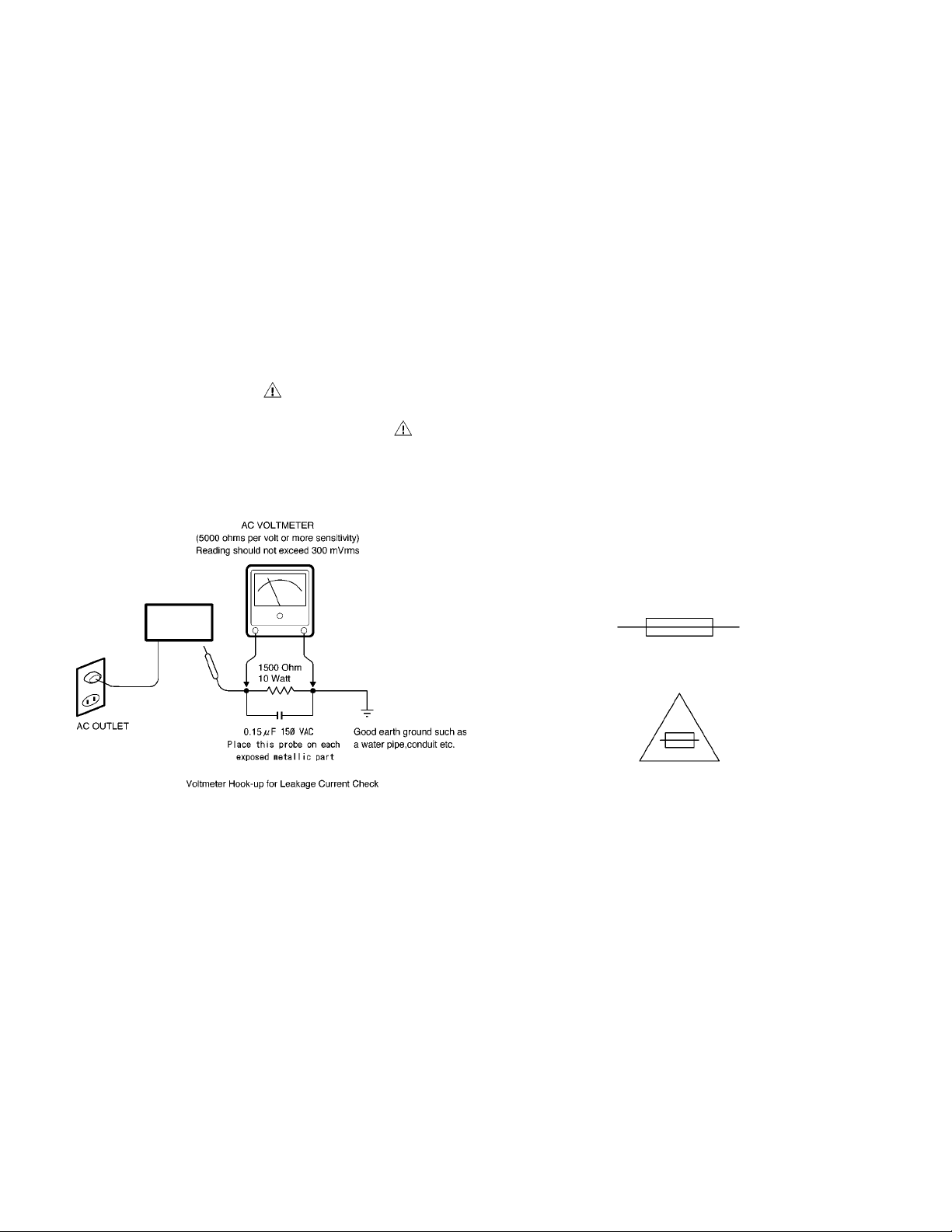
3. Before returning the set to the customer, always perform an
AC leakage current check on the exposed metallic parts of
the cabinet, such as terminals, screwheads, metal overlays, etc. to be sure that the set is safe to operate without
the danger of electrical shock, Plug the AC line cord directly
into a 120 V AC outlet. (Do not use a line isolation transformer during this check.) Use an AC voltmeter with a
sensitivity of 5000 ohms per volt (or more) as follows:
Connect a 1500 ohms, 10 watt resistor, paralleled by a 0.15
mfd, 150 VAC capacitor, between a known good earth
ground (water pipe, conduit, etc.) and the exposed metallic
parts, one at a time. Measure the AC voltage across the
1500 ohms resistor and 0.15 mfd capacitor combination.
Reverse the AC plug at the AC outlet and repeat the AC
voltage measurements for each exposed metallic part. The
measured voltage must not exceed 300 mVrms. This
corresponds to 200 µA AC. Any value exceeding this limit
constitutes a potential shock hazard and must be corrected
immediately.
4. Fuse symbol marks.
For CANADA
For U.S.A.
Fuse rating is marked at
adjacent fuse.
UNDERWRITERS LABORATORIES Standard
CAUTION "Risk of fire-replace fuse as marked"
– 2 –

SPECIFICATIONS
VM-6609
Picture tube :
Resolution :
Scanning frewuency :
Input terminals :
Outout terminals :
Sub Adjusting control :
Termination switch :
Operating environment :
Power source :
Power consumption :
Dimension (W x H x D ) :
System :
VIDEO A
VIDEO B
VIDEO A
VIDEO B
Weight :
EIA standard
9˝ measured diagonally, 90° deflection angle
More than 800 TV lines (center)
Horizontal: 15.75 kHz (EIA), Vertical: 60 Hz (EIA)
Composite video: 1 line, BNC connector, 1.0 V p-p 75 ohm negative sync
Composite video: 1 line, BNC connector, 1.0 V p-p 75 ohm negative sync
Composite video: 1 line, BNC connector, 1.0 V p-p 75 ohm negative sync
Composite video: 1 line, BNC connector, 1.0 V p-p 75 ohm negative sync
Focus volume
Sub bright volume
Vertical size volume
Manual switchable, Hi/ 75 ohm (Lo)
Temperature: -10
AC 100 to 240 V 50/60 Hz
20 Watts
222 x 238 x 250 mm
4.5 kg
°C to 40 °C, Humidity:10% to 90 %
VM-6609P
Operating environment :
Dimension (W x H x D ) :
System :
Picture tube :
Resolution :
Scanning frewuency :
Input terminals :
VIDEO A
VIDEO B
Outout terminals :
VIDEO A
VIDEO B
Sub Adjusting control :
Termination switch :
Power source :
Power consumption :
Weight :
CCIR standard
9˝ measured diagonally, 90
More than 800 TV lines (center)
Horizontal: 15.625 kHz (CCIR), Vertical: 50 Hz (CCIR)
Composite video: 1 line, BNC connector, 1.0 V p-p 75 ohm negative sync
Composite video: 1 line, BNC connector, 1.0 V p-p 75 ohm negative sync
Composite video: 1 line, BNC connector, 1.0 V p-p 75 ohm negative sync
Composite video: 1 line, BNC connector, 1.0 V p-p 75 ohm negative sync
Focus volume
Sub bright volume
Vertical size volume
Manual switchable, Hi/ 75 ohm (Lo)
Temperature: -10 °C to 40 °C, Humidity:10% to 90 %
AC 100 to 240 V 50/60 Hz
20 Watts
222 x 238 x 250 mm
4.5 kg
° deflection angle
– 3 –
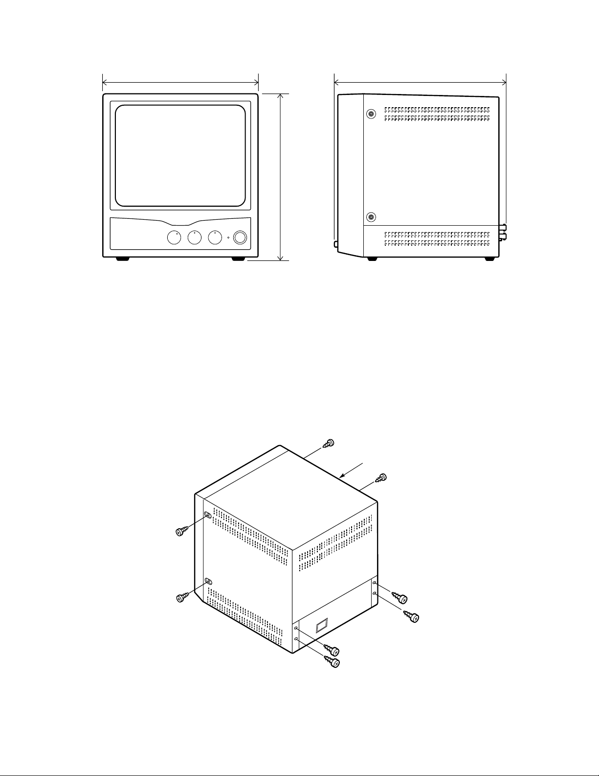
WD
(1)
H
Fig. 1
DISASSEMBLY
(1)
(1)
METAL TOP COVER
(1)
(1)
(1)
(1)
Fig. 2
– 4 –
(1)
1. OPERATING INSTRUCTIONS
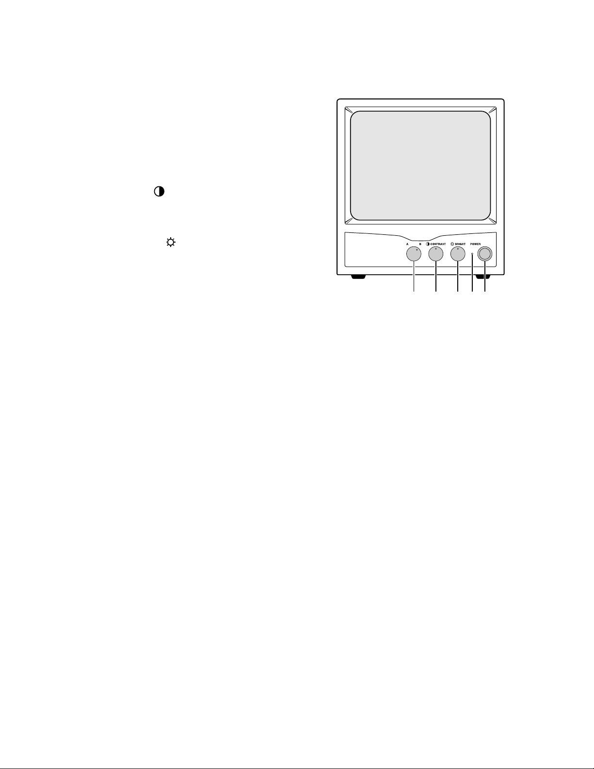
1-1. FRONT PANEL CONTROLS
1. Monitor Selector Switch (VIDEO A/B)
Turn this Monitor selector switch A position for a
signal fed through the rear panel VIDEO A
connectors.
Then, turn this Monitor selector switch B position for a signal fed through the rear panel
VIDEO B connectors.
2. Contrast Control ( CONTRAST)
Turn to adjust picture contrast according to your
requirement.
3. Brightness Control ( BRIGHT)
Turn to adjust picture brightness according to
your requirement.
4. Power Indicator
Lights when the power is on.
Lit: When the power is on.
Unlit: When the power is off.
5. Power Switch (POWER)
Press this switch to turn the power on or off.
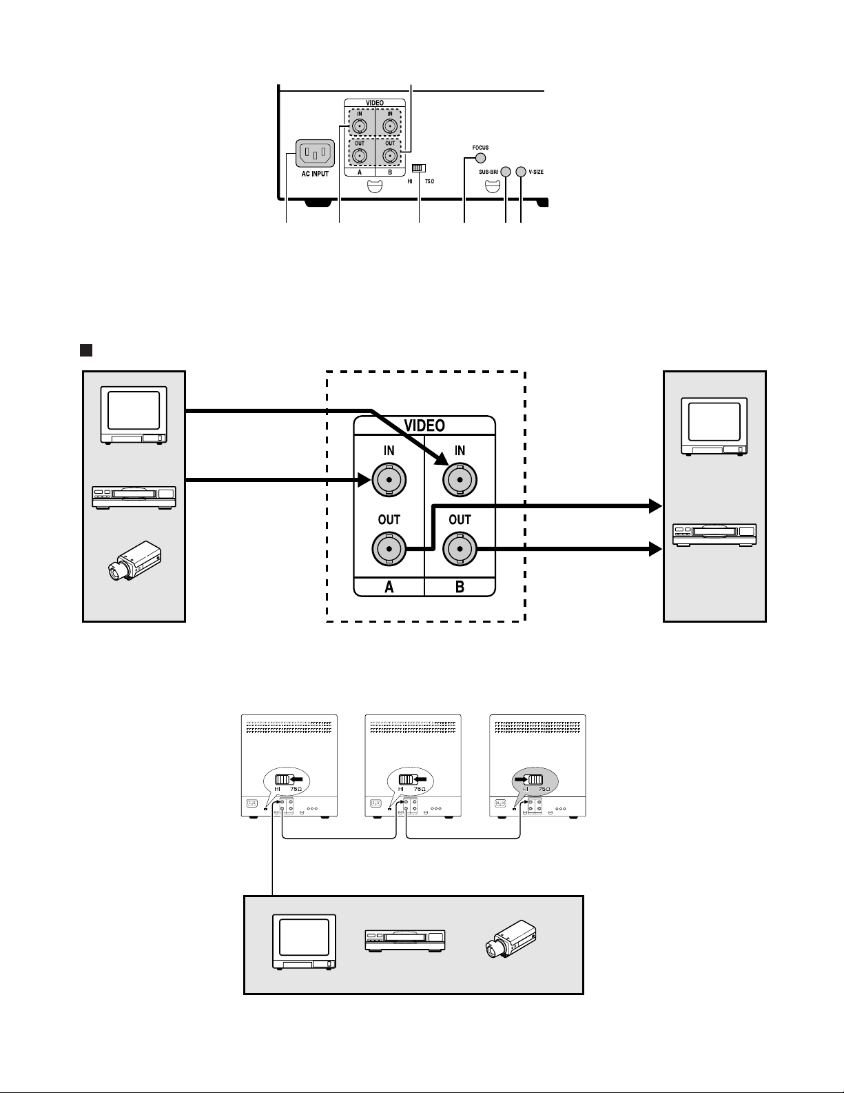
1-2. REAR PANEL CONTROLS & CONNECTION
1. AC input socket (AC INPUT)
Connect the AC power cord (supplied) securely
to this socket and to a wall outlet.
2. Video input terminals (VIDEO IN)
These terminals are used to input a video signal
source to this monitor.
Connect to the video output of a VCR or another monitor (for loop through connection) or to
a video camera.
3. Video output terminals (VIDEO OUT)
These terminals are used to output a video
signal from this monitor.
Loop-through output of the video in BNC
connector, then connect to the video input of
another monitor or a VCR.
54321
Fig. 3
However, the last monitor termination switch
should be the 75 ohm position for proper line
termination.
5. Focus control (FOCUS)
Turn to adjust picture focus to optimum focus.
6. Sub-brightness control (SUB-BRI)
Turn to adjust picture brightness.
7. Vertical Size control (V-SIZE)
Turn to adjust picture vertical size of the picture.
4. Termination Switch (HI/75 Ω (Lo))
Select the input impedance (HI/75 ohm).
When using only one monitor, turn the termination switch to the 75 ohm position. When using
more than one monitor, set all of the termination
switch to the monitors to the HI position.
– 5 –
3
Single Connection
To Video B
INPUT terminal
(Video signal cable)
Monitor
Video recorder
Video camera
To Video A
INPUT terminal
(Video signal cable)
1
2
4
5
7
6
Fig. 4
Monitor
To Video input
terminal
To Video input
terminal
Video recorder
(Rear panel)
Fig. 5
Coaxial cable
To Video input terminal
Monitor Video recorder
Fig. 6
Video camera
– 6 –

2. SERVICE ADJUSTMENTS
1357
7531
1
3
5
1
3
5
5
3
1
5
3
1
ADJUSTMENT
ITEM
HORIZONTAL
HOLD ADJUSTMENT
VERTICAL
SIZE ADJUSTMENT
HORIZONTAL
WIDTH ADJUSTMENT
VERTICAL
LINEARITY
ADJUSTMENT
FOCUS
ADJUSTMENT
TIMING
PATTERN
PATTERN GENERATOR
MODE CROSS-HATCHED
PATTERN
PATTERN GENERATOR
MODE MONOSCPE
PATTERN
PATTERN GENERATOR
MODE CROSS-HATCHED
PATTERN
PATTERN GENERATOR
MODE CROSS-HATCHED
PATTERN
PATTERN GENERATOR
MODE CROSS-HATCHED
PATTERN
SETTING
CONTRAST VR
AND BRIGHT
VR TO CENTER.
CONTRAST VR
AND BRIGHT
VR TO CENTER.
CONTRAST VR
AND BRIGHT
VR TO CENTER.
CONTRAST VR
AND BRIGHT
VR TO CENTER.
CONTRAST VR
AND BRIGHT
VR TO CENTER.
VR
LOCATION
VR404
VR302
VR304
L402
VR301
VR405
ADJUSTMENT PROCEDURE
Turn off horizontal sync. (pin to ground)
Adjust VR404 to make pattern upright.
Set the power switch "ON" and adjust
VR302 and VR304 until height for eye
comfort is obtained.
Horizontal width is adjusted by means of
the width coil L402 on the main PWB,
width standard hexagonal alignment tool.
Adjust L402 to make picture width within
"2" position.
Adjust the vertical linearity control VR301
for equal spaceing of lines between the
center extreme of scan.
The focus control may be adjusted for
optimum focus by VR405.
RASTER
CENTERING
ADJUSTMENT
RASTER TILT
ADJUSTMENT
BRIGHTNESS
ADJUSTMENT
VERTICAL
HOLD ADJUSTMENT
INTERLACE
ADJUSTMENT
PATTERN GENERATOR
MODE CROSS-HATCHED
PATTERN
PATTERN GENERATOR
MODE CROSS-HATCHED
PATTERN
PATTERN GENERATOR
MODE FULL-WHITE
PATTERN
PATTERN GENERATOR
MODE MONOSCPE
PATTERN
CAMERA SIGNAL
CONTRAST VR
AND BRIGHT
VR TO CENTER.
CONTRAST VR
AND BRIGHT
VR TO CENTER.
CONTRAST VR
AND BRIGHT
VR TO MAX.
CONTRAST VR
AND BRIGHT
VR TO CENTER.
CONTRAST VR
AND BRIGHT
VR TO CENTER.
VR402
VR303
VR303
The raster is centered by rotating the two
small at the rear of the yoke.
Loosen the screw on the rear of deflection
yoke, rotating the yoke to correct position
tighten the screw.
Brightness can be controlled by VR406
and VR201 is the main control which is
controlled at exeternal side of front side.
VR402 is a sub-bright control which is
located on the main PWB.
The vertical hold is automatic stop rolling.
But can't hold must adjust VR303.
Adjust VR303 have gap of vertical scan
line distinguish clearly.
Fig. 7
– 7 –

MAIN BOARD
(Foil side)
VR405
FOCUS
VR404
H-HOLD
VR402
SUB-BRITE
T403
L402
VR302
V-SIZE
E
C
B
Q405
SW901
T902
LED1
VR BOARD
(Foil side)
VR406
BRIGHTNESS
Fig. 8
VR201
CONTRAST
VR304
SUB-SIZE
VR303
INTERLACE
VR301
V-LINE
MAIN BOARD
VR BOARD
SW202
CHANNEL
Fig. 9
– 8 –

3. PARTS LIST
Note:
Alphabetic caracters enclosed by ( ) in the descriptions indicate destination for the VM-6609P.
VM-6609P(AU): Australia VM-6609P(XE): Europe VM-6609P(UK): United Kingdom
VM-6609: NTSC area (U.S.A., Canada)
LOCATION
CABINET & CHASSIS PARTS
1 645 046 0517 FRONT PANEL MT-9S OC-00067
1 645 047 0646 FRONT PANEL MT-9S AA-51
2 645 046 0487 VR KNOB MT-9 OC-00067
2 645 047 0622 VR KNOB MT-9 AA-51 [VM-6609P(XE),(AU)]
3 645 046 0494 SW KNOB MT-9 OC-00067
3 645 047 0639 SW KNOB MT-9 AA-51 [VM-6609P(XE),(AU)]
4 645 046 0432 LOGO MT-9AL OC-00067
4 645 047 0547 LOGO MT-9 AL AA-51 [VM-6609P(XE),(AU)]
5 645 046 0500 LED LENS MT-9/12/15/20
6 645 046 1019 VR ASS’Y MT-9S
7 645 046 0951 BRACKET LEFT MM-9M
8 645 046 0944 BRACKET RIGHT MM-9M
9 645 046 0722 PCB GUIDE RALL PCB MM-9M
PARTS NO. DESCRIPTION
[VM-6609,VM-6609P(UK.)]
[VM-6609P(XE),(AU.)]
[VM-6609,VM-6609P(UK)]
[VM-6609,VM-6609P(UK)]
[VM-6609,VM-6609P(UK)]
LOCATION
10 645 046 0968 BASE MM-9M
11 645 046 0999 FOOT PAD GL-19-B
12 645 046 0470 FOOT PAD RIVET MM-9M GL-19-B
13 645 046 0753 CRT MI0908P4AU CPT
14 645 034 3599 PH W/W SCR. 4*18MM
15 645 046 1057 VIDEO BOARD MT-9S
16 645 046 0975 METAL TOP COVER MT-9 AA-51
17 645 034 3582 PH W/W SCR. 4*8MM
18 645 034 3841 ID LABEL 83*51MM (N.S.P.)
19 645 046 1064 MAIN BOARD MM-9S
20 645 046 0982 JACK PLATE MT-9S AA-51
21 645 035 6216 BH SCREW 4*6MM
22 645 034 3612 SCREW+WASHER 3*6MM
23 645 046 0593 CRT GND WIRE/1015 22AWG
24 645 035 6223 WASHER OUT TEETH 4.5*8.5*0.5MM
25 645 046 4942 BNC WASHER
26 645 046 4898 BNC NUT
27 645 046 0401 BNC CONNECTOR BNC 13-28 75OHM
28 645 046 1026 AC SOCKET ASS’Y MM-9
29 645 046 0814 YOKE MM-9
PARTS NO. DESCRIPTION
N.S.P.: Not available as service parts.
1
4
2
3
7
8
13
14
5
6
29
23
16
17
15
18
9
22
VM-6609
10
11
12
19
25
21
20
26
24
27
28
9

ELECTRICAL PARTS
Note:
1. Materials of Capacitors and Resistors are abbreviated as follows ;
Resistors Capacitors
CF RES Carbon Film Resistor MEF CAP Metallized Polyester Film Capacitor
MF RES Metal Film Resistor (Non-inductive)
MOF RES Metallized Oxide Film Resistor MEMB CAP Mini Box Metallized Polyester Capacitor
PEI CAP Polyester Film Capacitor (Inductive)
PPN CAP Polypropylene Film Capacitor (Non-inductive)
PPS CAP Polypropylene and Metallized Polypropylene
MPP CAP Metallized Polypropylene Capacitor
X CAP(MKP) Metallized Polypropylene Film Capacitor
CC CAP Ceramic Capacitor
EC CAP Electrolytic Capacitor
2. N.S.P. : Not available as service parts.
(Non-inductive)
Film Capacitor (Non-inductive)
(Non-inductive)
(Non-inductive)
LOCATION
PARTS NO. DESCRIPTION
MAIN BOARD MM-9S
645 046 1064
C207 645 034 2738 EC CAP 2.2UF 50V T
C208 645 034 2714 EC CAP 220UF 16V T
C209 645 040 8991 PEI CAP .033UF 50V 5% T
C210 645 046 0036 PEI CAP .0027UF 50V 5% T
C301 645 034 2936 PEI CAP .1UF 50V 5% T
C302 645 040 8953 CC CAP 103PF 50V Y5P T
C303 645 034 2653 EC CAP 1000UF 16V 10DIA.
C304 645 046 0005 CC CAP 222PF 50V Y5P T
C305 645 034 2936 PEI CAP .1UF 50V 5% T
C306 645 034 2936 PEI CAP .1UF 50V 5% T
C307 645 034 2936 PEI CAP .1UF 50V 5% T
C308 645 046 0029 CC CAP 47PF 50V 5% T
C309 645 034 2936 PEI CAP .1UF 50V 5% T
C310 645 034 2653 EC CAP 1000UF 16V 10DIA.
C311 645 034 2608 EC CAP 100UF 16V T
C312 645 045 9962 EC CAP 47UF 25V T
C313 645 044 3695 EC CAP 10UF 50V T
C314 645 046 0098 MEMB CAP .1UF 100V 5% T
C402 645 046 0043 PEI CAP .039UF 100V 5% T
C403 645 034 3018 MEMB CAP .01UF 63V 5% T
C405 645 034 3018 MEMB CAP .01UF 63V 5% T
C406 645 034 2929 PEI CAP .01UF 50V 5% T
C407 645 034 2936 PEI CAP .1UF 50V 5% T
C408 645 034 2783 EC CAP 470UF 16V T
C409 645 040 8953 CC CAP 103PF 50V Y5P T
C410 645 034 2929 PEI CAP .01UF 50V 5% T
C411 645 034 2677 EC CAP 1UF 50V T
C412 645 045 9993 CC CAP 102PF 1KV Z5U T
C413 645 046 0074 PPN CAP .0056UF 50V 5% T
C414 645 046 0067 PPN CAP .018UF 630V 5% 15MM
C415 645 045 9955 EC CAP 220UF 25V T
C417 645 046 0050 MEF CAP 3.3UF 100V 5% 20MM
C418 645 045 9979 EC CAP 470UF 25 V
C421 645 043 3139 CC CAP 103PF 1.5KV Z5U 10MM
C422 645 034 2745 EC CAP 2.2UF 250V T
C423 645 045 9986 EC CAP 4.7UF 160V T
C901 645 034 3070 X CAP .1UF 250V 10% 15MM
C901 645 040 9066 X CAP .1UF 275V 20% 15MM
C903 645 034 3087 Y CAP 472PF 400V 20%
C904 645 034 3087 Y CAP 472PF 400V 20%
C905 645 034 3087 Y CAP 472PF 400V 20%
C906 645 045 9948 EC CAP 100UF 400V 22DIA.
C907 645 034 2813 CC CAP 103PF 1KV Z5U 10MM
C908 645 046 0098 MEMB CAP .1UF 100V 5% T
C909 645 034 3025 MEMB CAP .22UF 63V 5% T
C910 645 044 3695 EC CAP 10UF 50V T
C911 645 034 2653 EC CAP 1000UF 16V 10DIA.
C912 645 034 2653 EC CAP 1000UF 16V 10DIA.
C914 645 034 2813 CC CAP 103PF 1KV Z5U 10MM
C920 645 034 2653 EC CAP 1000UF 16V 10DIA.
C925 645 046 0098 MEMB CAP .1UF 100V 5% T
(CAPACITORS)
LOCATION
D301 645 034 3377 RECTIFIER DIODE 1N4003 T 52MM
D401 645 046 0272 RECTIFIER DIODE BYT56J
D402 645 046 0272 RECTIFIER DIODE BYT56J
D404 645 046 0272 RECTIFIER DIODE BYT56J
D405 645 034 3346 RECTIFIER DIODE BYT52M T52MM
D406 645 046 0265 RECTIFIER DIODE PS106R T
D407 645 046 0265 RECTIFIER DIODE PS106R T
D408 645 034 3315 DIODE 1N4148 T 52MM
OR 645 034 3308 DIODE 1N4148 T
D901 645 046 0241 RECTIFIER DIODE 1N4007 T 52MM
D902 645 046 0241 RECTIFIER DIODE 1N4007 T 52MM
D903 645 046 0241 RECTIFIER DIODE 1N4007 T 52MM
D904 645 046 0241 RECTIFIER DIODE 1N4007 T 52MM
D905 645 046 0234 RECTIFIER DIODE PG106R T 52MM
D906 645 046 0258 RECTIFIER DIODE BA159 T 52MM
D907 645 046 0234 RECTIFIER DIODE PG106R T 52MM
D909 645 046 0289 RECTIFIER DIODE 30DF2 20MM
ZD901 645 046 0227 ZENER DIODE HZ6A2 T
F901 645 046 0821 FUSE 2A/250V SLOWBLOW 5*20MM
IC301 645 046 0128 LINEAR IC TDA1175P
IC401 645 046 0104 LINEAR IC LM1391N
OR 645 046 0111 LINEAR IC MC1391P
IC901 645 034 6231 LINEAR IC 4N35 W=10MM
Q903 645 034 3162 REGULATOR IC TL431 T
OR 645 034 3179 REGULATOR IC KA431 T
L401 645 046 0883 CHOCK COIL 20 UH 20%
OR 645 046 0876 CHOCK COIL 20 UH 20%
OR 645 046 0890 CHOCK COIL 20 UH 20%
L402 645 046 0838 WIDTH COIL VM-14AF
OR 645 046 0845 WIDTH COIL VM-14AF
L402 645 046 0852 WIDTH COIL VM-14AF
L403 645 046 0869 LINEARITY COIL 15 UH 20%
L404 645 046 0906 PEAKING COIL 33 UH 10% T
L903 645 046 0883 CHOCK COIL 20 UH 20%
OR 645 046 0876 CHOCK COIL 20 UH 20%
OR 645 046 0890 CHOCK COIL 20 UH 20%
Q205 645 034 3209 TR 2SA733P T
OR 645 046 0210 TR KSA733CG T
Q301 645 046 0203 TR 2SD667C T
OR 645 046 0142 TR 2SC2235 T
Q401 645 034 3254 TR 2SC945 T
OR 645 034 3216 TR 2SC1815GR T
Q403 645 046 0159 TR 2SC1959Y T
Q405 645 046 0166 TR 2SC4161M
Q901 645 046 0180 TR 2SC3866 -MR
OR 645 046 0173 TR 2SC3447M
Q902 645 046 0135 TR 2SC1213 T
R201 645 034 2356 CF RES 75OHM 1/4W 5% T 52MM
PARTS NO. DESCRIPTION
(DIODES)
(FUSE)
(INTEGRATED CIRCUITS)
(INDUCTORS)
(SEMICONDUCTORS)
(RESISTORS)
10

LOCATION
R222 645 045 9610 CF RES 200OHM 1/4W 5% T 52MM
R223 645 045 9764 CF RES 680KOHM 1/4W 5% T 52MM
R224 645 034 2028 CF RES 220OHM 1/4W 5% T 52MM
R225 645 034 2271 CF RES 560OHM 1/4W 5% T 52MM
R226 645 034 2271 CF RES 560OHM 1/4W 5% T 52MM
R228 645 045 9641 CF RES 2.2MOHM 1/2W 5% T 52MM
R229 645 034 2042 CF RES 2.2KOHM 1/4W 5% T 52MM
R231 645 045 9627 CF RES 200KOHM 1/4W 5% T 52MM
R301 645 045 9825 MOF RES 1OHM 1W 5% 15MM
R303 645 040 8809 CF RES 33KOHM 1/4W 5% T 52MM
R304 645 045 9719 CF RES 5.1KOHM 1/4W 5% T 52MM
R305 645 034 2059 CF RES 22KOHM 1/4W 5% T 52MM
R306 645 034 2202 CF RES 4.3KOHM 1/4W 5% T 52MM
R307 645 040 8724 CF RES 1OHM 1/2W 5% T 52MM
R308 645 034 2240 CF RES 4.7KOHM 1/4W 5% T 52MM
R309 645 045 9764 CF RES 680KOHM 1/4W 5% T 52MM
R311 645 034 2042 CF RES 2.2KOHM 1/4W 5% T 52MM
R312 645 045 9603 CF RES 18KOHM 1/4W 5% T 52MM
R313 645 034 2226 CF RES 47OHM 1/4W 5% T 52MM
R314 645 045 9801 MF RES 270KOHM 1/4W 1% T 52MM
R315 645 034 1991 CF RES 150KOHM 1/4W 5% T 52MM
R316 645 034 1892 CF RES 100KOHM 1/4W 5% T 52MM
R317 645 045 9696 CF RES 3.3OHM 1/4W 5% T 52MM
R318 645 034 2288 CF RES 5.6KOHM 1/4W 5% T 52MM
R319 645 034 2042 CF RES 2.2KOHM 1/4W 5% T 52MM
R320 645 045 9788 CF RES 820KOHM 1/4W 5% T 52MM
R401 645 045 9849 MOF RES 22OHM 3W 5% 20MM
R402 645 045 9740 CF RES 62OHM 1/4W 5% T 52MM
R403 645 034 2004 CF RES 2KOHM 1/4W 5% T 52MM
R404 645 034 2103 CF RES 2.7KOHM 1/4W 5% T 52MM
R405 645 034 2363 CF RES 820OHM 1/4W 5% T 52MM
R406 645 045 9757 CF RES 620OHM 1/2W 5% T 52MM
R407 645 045 9870 MOF RES 270OHM 1W 5% 15MM
R408 645 034 2042 CF RES 2.2KOHM 1/4W 5% T 52MM
R409 645 043 3160 CF RES 1.3KOHM 1/4W 5% T 52MM
R410 645 045 9726 CF RES 56KOHM 1/4W 5% T 52MM
R411 645 034 2288 CF RES 5.6KOHM 1/4W 5% T 52MM
R412 645 034 1861 CF RES 1KOHM 1/4W 5% T 52MM
R413 645 045 9689 CF RES 33KOHM 1/2W 5% T 52MM
R414 645 045 9634 CF RES 2.2KOHM 1/2W 5% T 52MM
R415 645 034 1922 CF RES 12KOHM 1/4W 5% T 52MM
R417 645 045 9764 CF RES 680KOHM 1/4W 5% T 52MM
R418 645 045 9672 CF RES 270KOHM 1/4W 5% T 52MM
R419 645 045 9580 CF RES 1MOHM 1/4W 5% T 52MM
R420 645 045 9733 CF RES 560KOHM 1/4W 5% T 52MM
R421 645 045 9764 CF RES 680KOHM 1/4W 5% T 52MM
R424 645 034 2011 CF RES 22OHM 1/4W 5% T 52MM
R426 645 045 9894 MOF RES 6.2KOHM 2W 5% 20MM
R901 645 045 9771 CF RES 680KOHM 1/2W 5% T 52MM
R902 645 045 9863 MOF RES 220KOHM 2W 5% 15MM
R903 645 045 9917 CEMENT RES 22KOHM 5W 5% 5MM
R904 645 034 2257 CF RES 47KOHM 1/4W 5% T 52MM
R905 645 034 1861 CF RES 1KOHM 1/4W 5% T 52MM
R906 645 034 1861 CF RES 1KOHM 1/4W 5% T 52MM
R907 645 045 9887 MOF RES 330OHM 1W 5% 12.5MM
R908 645 034 2042 CF RES 2.2KOHM 1/4W 5% T 52MM
R909 645 045 9566 CF RES 100OHM 1/4W 5% T 52MM
R910 645 034 2257 CF RES 47KOHM 1/4W 5% T 52MM
R911 645 045 9832 MOF RES 120OHM 1W 5% 15MM
R912 645 034 2264 CF RES 51OHM 1/4W 5% T 52MM
R914 645 034 1861 CF RES 1KOHM 1/4W 5% T 52MM
R915 645 045 9818 MF RES 4.75KOHM 1/4W 1% T 52MM
R916 645 045 9795 MF RES 1.21KOHM 1/4W 1% T 52MM
R917 645 045 9900 FUSE RES 0.56OHM 1W 5% 15MM
R918 645 034 2318 CF RES 680OHM 1/4W 5% T 52MM
R919 645 034 1878 CF RES 10KOHM 1/4W 5% T 52MM
R921 645 034 1878 CF RES 10KOHM 1/4W 5% T 52MM
R922 645 045 9924 W-W RES 3.9OHM 3W 5% 5MM
SW201 645 046 0418 SLIDE SWITCH SS004-P012BJ-PA6
T401 645 046 0777 DRIVE TRANS. VM-14AF
OR 645 046 0784 DRIVE TRANS. VM-14AF
OR 645 046 0791 DRIVE TRANS. VM-14AF
T403 645 046 0807 FBT TRANS. MM-9M
T901 645 046 0920 LINE FILTER TM-14T 20MH
T902 645 046 0760 POWER TRANS. MM-9 VDE
PARTS NO. DESCRIPTION
(SWITCH)
(TRANSFORMERS)
LOCATION
VR301 645 034 3483 POT VR 100KOHM 6DIA.
VR302 645 046 0340 POT VR 500KOHM 6DIA.
VR303 645 034 3520 POT VR 50KOHM 6DIA.
VR304 645 046 0333 POT VR 250KOHM 6DIA.
VR402 645 046 0340 POT VR 500KOHM 6DIA.
VR404 645 034 3476 POT VR 10KOHM 6DIA.
VR405 645 046 0326 POT VR 2MOHM15DIA.
TP1 645 046 0371 CONNECTOR BASE 1038H
B402 645 046 0395 CONNECTOR BASE M11384
B404 645 034 3773 CONNECTOR BASE M241855
B902 645 034 3735 CONNECTOR BASE M241833-X
B903 645 034 3735 CONNECTOR BASE M241833-X
BNC02 645 034 3674 CONNECTOR BASE M241852
PARTS NO. DESCRIPTION
(VARIABLE RESISISTERS)
(MISCELLNEOUS)
645 034 4404 FUSE CLIP BOARD TYPE 5*20MM
645 046 0548 LEAD WIRE/1007 24AWG 7MM
645 046 0609 L/W HOUSING 1007/1185 24/26
645 046 0616 L/W HOUSING 1015 24AWG L=220
VIDEO BOARD MT-9S
645 046 1057
C201 645 034 2684 EC CAP 22UF 16V T
C202 645 046 0029 CC CAP 47PF 50V 5% T
C203 645 046 0081 EC CAP 10UF 50V 20% T
C204 645 034 2783 EC CAP 470UF 16V T
C205 645 046 0012 CC CAP 272PF 50V Y5P T
C206 645 034 2608 EC CAP 100UF 16V T
C211 645 045 9993 CC CAP 102PF 1KV Z5U T
C212 645 043 3139 CC CAP 103PF 1.5KV Z5U 10MM
C213 645 045 9931 EC CAP 100UF 100 V
C215 645 034 2714 EC CAP 220UF 16V T
C216 645 045 9955 EC CAP 220UF 25V T
D201 645 034 3315 DIODE 1N4148 T 52MM
OR 645 034 3308 DIODE 1N4148 T
L201 645 046 0913 PEAKING COIL 4.7 UH 10% T
Q201 645 034 3216 TR 2SC1815GR T
OR 645 034 3254 TR 2SC945 T
Q202 645 034 3209 TR 2SA733P T
OR 645 046 0210 TR KSA733CG T
Q203 645 034 3216 TR 2SC1815GR T
OR 645 034 3254 TR 2SC945 T
Q204 645 046 0197 TR 2SD1609C
R202 645 040 8755 CF RES 16KOHM 1/4W 5% T 52MM
R203 645 045 9719 CF RES 5.1KOHM 1/4W 5% T 52MM
R204 645 045 9566 CF RES 100OHM 1/4W 5% T 52MM
R205 645 034 2318 CF RES 680OHM 1/4W 5% T 52MM
R206 645 034 2028 CF RES 220OHM 1/4W 5% T 52MM
R207 645 034 2134 CF RES 330OHM 1/4W 5% T 52MM
R208 645 045 9665 CF RES 240OHM 1/4W 5% T 52MM
R209 645 045 9566 CF RES 100OHM 1/4W 5% T 52MM
R211 645 034 2011 CF RES 22OHM 1/4W 5% T 52MM
R212 645 034 1984 CF RES 15KOHM 1/4W 5% T 52MM
R213 645 034 2103 CF RES 2.7KOHM 1/4W 5% T 52MM
R214 645 045 9597 CF RES 150OHM 1/4W 5% T 52MM
R215 645 034 2226 CF RES 47OHM 1/4W 5% T 52MM
R216 645 034 2004 CF RES 2KOHM 1/4W 5% T 52MM
R217 645 034 2158 CF RES 3.6KOHM 1/4W 5% T 52MM
R218 645 045 9856 MOF RES 2.2KOHM 3W 5% 20MM
R219 645 034 2028 CF RES 220OHM 1/4W 5% T 52MM
R220 645 045 9658 CF RES 24OHM 1/2W 5% T 52MM
R221 645 045 9573 CF RES 1KOHM 1/2W 5% T 52MM
R227 645 045 9702 CF RES 47KOHM 1/2W 5% T 52MM
R233 645 034 2134 CF RES 330OHM 1/4W 5% T 52MM
SP201 645 035 9408 SPARK GAP DSP 200V 10% T
SP202 645 038 5520 SPARK GAP 250V 20% 5MM T
B201 645 034 3674 CONNECTOR BASE M241852
B202 645 038 5445 CONNECTOR BASE M241856
(CAPACITORS)
(DIODES)
(INDUCTOR)
(SEMICONDUCTORS)
(RESISTORS)
(SPARK GAPS)
(MISCELLANEOUS)
645 046 0524 CRT SOCKET CRT 7PIN 20DIA.
11

LOCATION
B203 645 034 3773 CONNECTOR BASE M241855
B204 645 046 0388 CONNECTOR BASE M241854
CRT GND 645 034 3667 CONNECTOR BASE P235142
PARTS NO. DESCRIPTION
VR ASS’Y MT-9S
645 046 1019
SW202 645 046 0425 ROTARY SWITCH 296S0947B
SW901 645 034 3810 POWER SWITCH SS-160-7
LED1 645 046 0296 LED 5DIA.
VR406 645 046 0319 VR 200KOHM 9DIA. 10MM ND F 15
VR201 645 046 0302 VR 500OHM 9DIA. 10MM ND F 15
B703 645 046 0388 CONNECTOR BASE M241854
B206 645 046 0654 SHIELD WIRE 2547 26AWG
B901 645 046 0623 L/W HOUSING/1015 18AWG
(SWITCH)
(LED)
(VARIABLE RESISTOR)
(MISCELLANEOUS)
645 046 0647 L/W HOUSING 1007/24 L=220
LOCATION
PARTS NO. DESCRIPTION
ACCESSORIES & PACKING MATERIALS
1 645 038 5933 POWER CORD NS8-5175N [VM-6609]
1 645 034 3971 POWER CORD 10-1VDE [VM-6609P(XE)]
1 645 040 9264 POWER CORD NS8-5181N [VM-6609P(UK)]
1 645 040 9257 POWER CORD NS8-5180N [VM-6609P(AU)]
2 645 046 0463 USER MANUAL CCTV [VM-6609]
2 645 047 0615 USER MANUAL CCTV [VM-6609P(XE),(AU),(UK)]
3 645 046 0449 CARTON MT-9S-EIA [VM-6609]
3 645 047 0561 CARTON MT-9S-CCIR [VM-6609P(XE),(AU),(UK)]
645 046 0739 POLYFORM MM-9M
12

K
H
G
4.CIRCUIT DIAGRAMS
BLOCK DIAGRAM
J
I
F
E
D
C
B
VR PWB
BRIGHT_VR
POWER LED
CONT_VR
B404
B206
1
2
3
4
5
YELLOW
2
3
4
RED
RED
BLUE
RED
BLACK
RED
WHITE
OVAEALL WIRING
MAIN PWBMAIN PWB
B403
4
VR402
3
R421
5
R914
1
GND
2
B204
R211
3
2
C203
R233
1
D406
VR405
R228
D408
L404
C207
ORANGE
YELLOW
WHITE
BLUE
GREEN
RED
WHITE
VIDEO PWB
B202
R221
2
4
C213
R227
6
B203
C212
1
Q203
2
C214(12V)
3
Q201
5
A
1 2 3 4 5 6 78
-13-

K
CRT
MAIN_PWB
VIDEO_PWB
VIDEO_PWB
VR_PWB
VR_PWB
MAIN_PWB
VR_PWB
J
I
H
G
F
E
D
C
B
A
MAIN CIRCUIT DIAGRAM
1 2 3 4 5 6 7 8
-14-

K
F901
2A/250V
R901
470K
1/2W
C901
0.1µ
250VAC
T901 50mH
LINE FILTER
R902
220K 2W
R17
0.68
1W
C902
0.1µ
250VAC
1N4007 x 4
D903
D904
D901
D902
C910
10µ
C903
4700P
400VAC
R901
680K
1/2W
C906
0.22µ
R907
330
1W
R910
47K
C906
100µ
400V
R903
22K
5W
D906
BA159
L903
20µH
C908
0.1µ
100V
C905
4700P 400VAC
IC901
D905
PG106R
R909
100
D907
FG106R
R908
2.2K
R906
1K
Q902
2SC1213
R919
10K
Q903
TL431
R918
680
Q901
2SC3866
L
N
G
MAIN_PWB
MAIN_PWB
ZR901
R922
3.9 3W
C904
4700P
400VAC
VR_PWB
C907
0.01µ
1KV
T902
R905
1K
R912
51
ZD901
6C2
R904
47K
C925
0.1µ
100V
R915
4.75K
R916
1.2K
R920
NONE
R921
10K
C920
1000µ
16V
R914
1K
VR_PWB
C912
1000µ
16V
C911
1000µ
16V
D909
30DF2
C914
0.01µ
1KV
R911
120
1W
J
I
H
G
F
E
D
C
B
POWER CIRCUIT DIAGRAM
A
1 2 3 4 5 6 78
-15-


Feb./ '01 / 2300 MI Printed in Japan
SANYO Electric Co.,Ltd.
Osaka, Japan
 Loading...