

Page 1
VDC-HD3300/HD300P
VDC-HD3100/HD3100P
Features of This Camera
Specifications
Name and Function of Each Compon ent
Connections
Lens Installation
Lens Adjustment
Viewing Firmware Version
Introduction1/15
Page 2
The camera supports network oper ation. By simply connectin g a LAN cable to it , you can construc t the most
advanced network monitoring system. From the Web browser (Internet Explorer) installed on your PC, you
can operate the camera via the network in an easy-to-use manner.
In addition, it is a PoE product th at can be power ed through a LAN cable, so you can install it in loc ations
where there is no power outlet nearby.
The camera has 4-megapixel CMOS sensor that produces clear images at ul tra- high resolution.
The camera can deliver full HD H.264 vide o thr oughout the network. Connect ing a high- definition monitor to
your PC enables full high-definit ion video monitoring.
The camera supports both H.2 64 vi deo and J PEG image compression formats, which y ou c an cho os e from
depending on the network environment.
The camera offers the focus assist function that support s focus ad jus tment at megapixel image resol ution,
allowing you to fine-tune the focus in optimal conditions in an easy manner.
The camera's motion sensor function can work in conjunction with any external alarm device, fac ilitating the
construction of a high-le vel security syste m.
Installing associated software applica tio ns on your PC further extends the capabilities of your surveillance system.
Introduction 2/15
Page 3

Image pickup device 1/3" CMOS sensor
Effective pixels 16:9 1920 (H) × 1080 (V), 4:3 2288 (H) × 1712 (V)
Lowest image
illumination
Video S/N ratio
Lens Built-in varifocal lens f=3 to 9mm, F1.2 to 2.1
Adjusting focus Focus assist functi on
Day/Night function Auto, color, black-a nd-white, alarm input switching
White balance Auto (ATW), one push (AWC), manual (R/B gain adjustable), indoor, outdoor,
Backlight compensation Multi-spot evaluative metering, center-weighted average metering, masking
Electronic sensitivity
boosting
Electronic shutter
Iris control DC iris lens supported
Camera settings
AGC gain Normal/Middle/High (Manual gain setting possible at Off)
Gamma correction 0.45, 1, Mode 1, Mode 2
Aperture compensation On/Off (Correction level adjustable)
VIVID COLOR EFFECT ON/OFF
DNR
Mirror H/V/HV/OFF
Privacy mask On/Off, max. 8 mas k patter n s
Motion sensor On (masking/detection area setting)/Off
Language selection
50IRE: 1.0 lx (at F1.2, color mode, high gain)
50IRE: 0.06 lx (at F1.2, black-and- white mode, high gain)
50dB (when AGC is “OFF”)
( (VDC-HD3300P/VDC-HD3300 only))
fluorescent
Auto (32× max) or Off
VDC-HD3300P/VDC-HD3100P: 1/25, 1/50, 1/120, 1/250, 1/500, 1/1000, 1/2000,
1/4000, 1/10000D
VDC-HD3300/VDC-310 0: 1/ 30, 1/ 60, 1/100, 1/250, 1/500, 1/1000, 1/2000, 1/4000,
1/10000
Long exposure shutter (1×, 2×, 4×, 8×, 16×, 32×)
Selectable between 2 camera setting patterns
ON/OFF
English, French, Germ an, Spanish, Japanese
Video output Composite output
LAN 10BASE-T/100BASE-TX (RJ-45 connector)
Alarm input 2 (NO/NC), also serve as Day/Night switch (VDC-HD3300P/VDC-HD 3300 only )
Alarm output
2 (NO/NC, 16V, 150 mA, open collector)
Introduction 3/15
Page 4
Image/video
H.264/JPEG
compression
Video size (H.264)
(16:9) 1920×1080, 1280×720, 640×360, 320×180
(4:3) 1600×1200, 1280×960, 1024×768, 640×480, 320×240
Video size (JPEG)
(16:9)1920×1080, 1280×720, 1024×576, 640×360
(4:3) 2288×1712, 1600×1200, 1280×960, 1024×768, 800×600, 640×48 0, 320×240
Picture quality
QUALITY mode: BASIC, NORMAL, ENHANCED, FI NE, SUPER FINE
BITRATE mode: User-spec ified bit rate
Interface 10BASE-T/100BASE-TX
Protocol TCP/IP, UDP, HTTP, HTTPS, SMTP, NTP, DHCP, FTP, DDNS, RTP, RTSP, RTCP
Simultaneous access 20
Security
BASIC authenticati on (ID/password), SSL, IP filtering
International Waterproof
IP66
and Dustproof Standard
Operating ambient
–10 to +50°C, 90% RH or less (no condensation)
temperature/humidity
Power source 12 to 15 VDC/24 VAC±10%, 50/60 Hz, PoE
Power consumption 4,6W, 18W (with heater turned on)
Weight 770 g
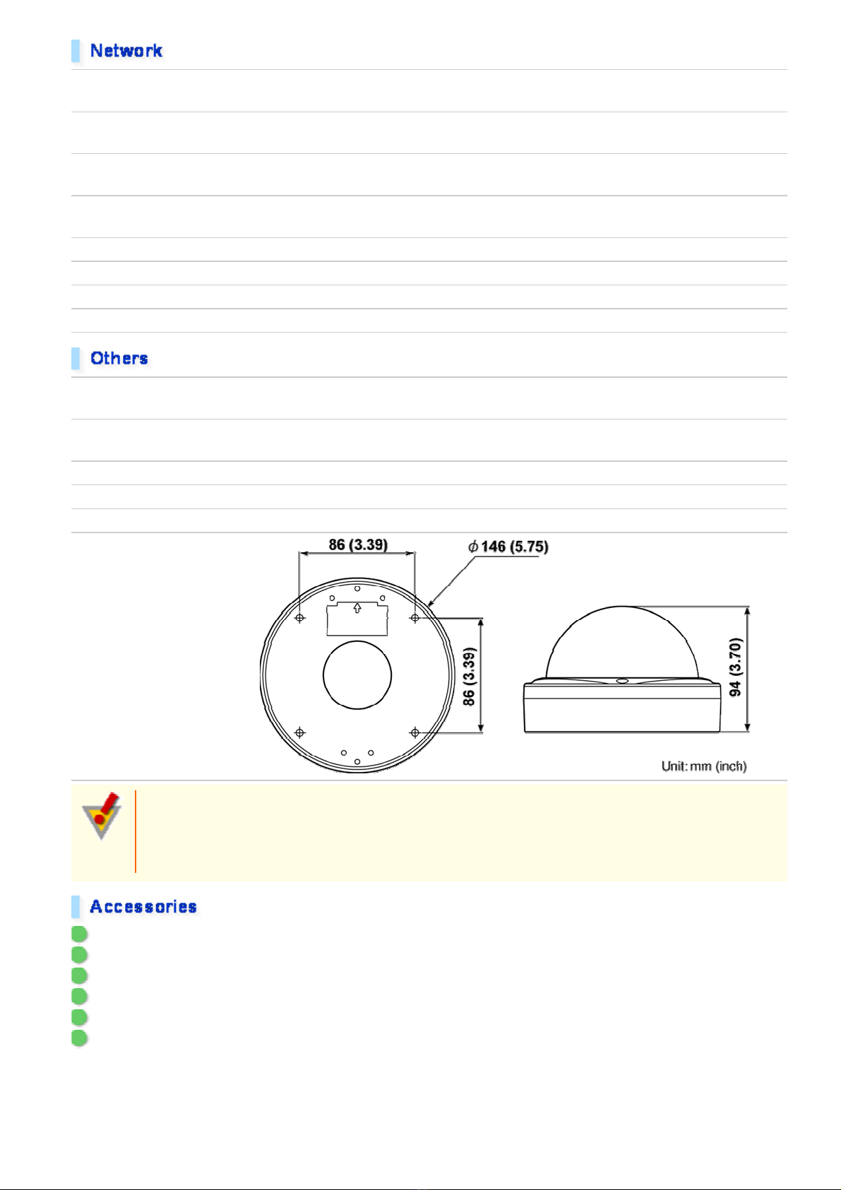
Dimensions
Approvals: IP66/CE
This unit has been certifie d to IP66 standards when properly installed.
Use only an IP66 certified encl os ure or an electrical box.
Ensure all openings in encl os ur e ar e sea led as per manuf ac turer's instructions.
1 Video cable
2 Cushioning sheet
3 Hexagonal wrench
4 Connector
5 Pattern sheet
6 CD-ROM
Introduction 4/15
Page 5
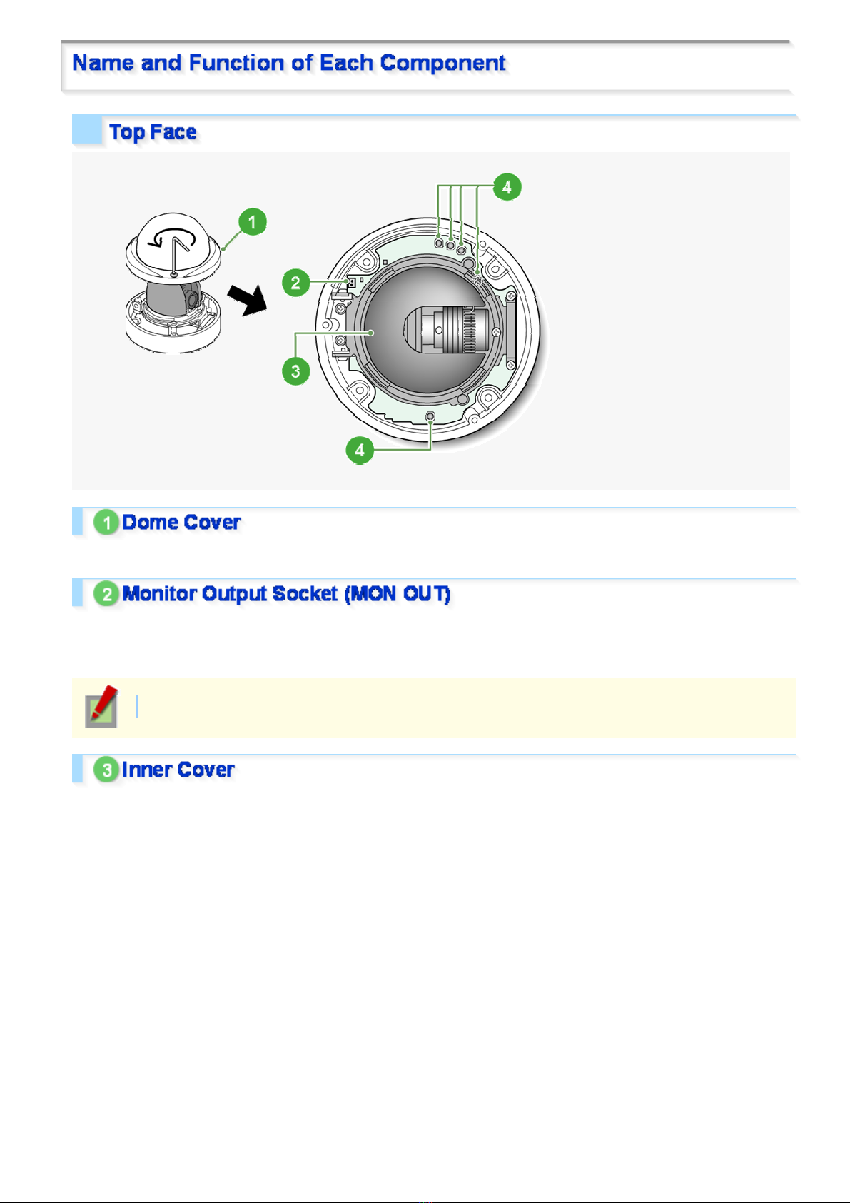
To remove the cover, remove the three screws using the supplied hex wrench.
Connecting the camera and monitor using the supplied cable enables you to perform focus and iris adjustments
while monitoring the live vi deo.
For details, see the “Connections” section.
You can use crocodile clip connectors instead of the supplied cable.
This cover protects the len s ass em bly .
Introduction 5/15
Page 6
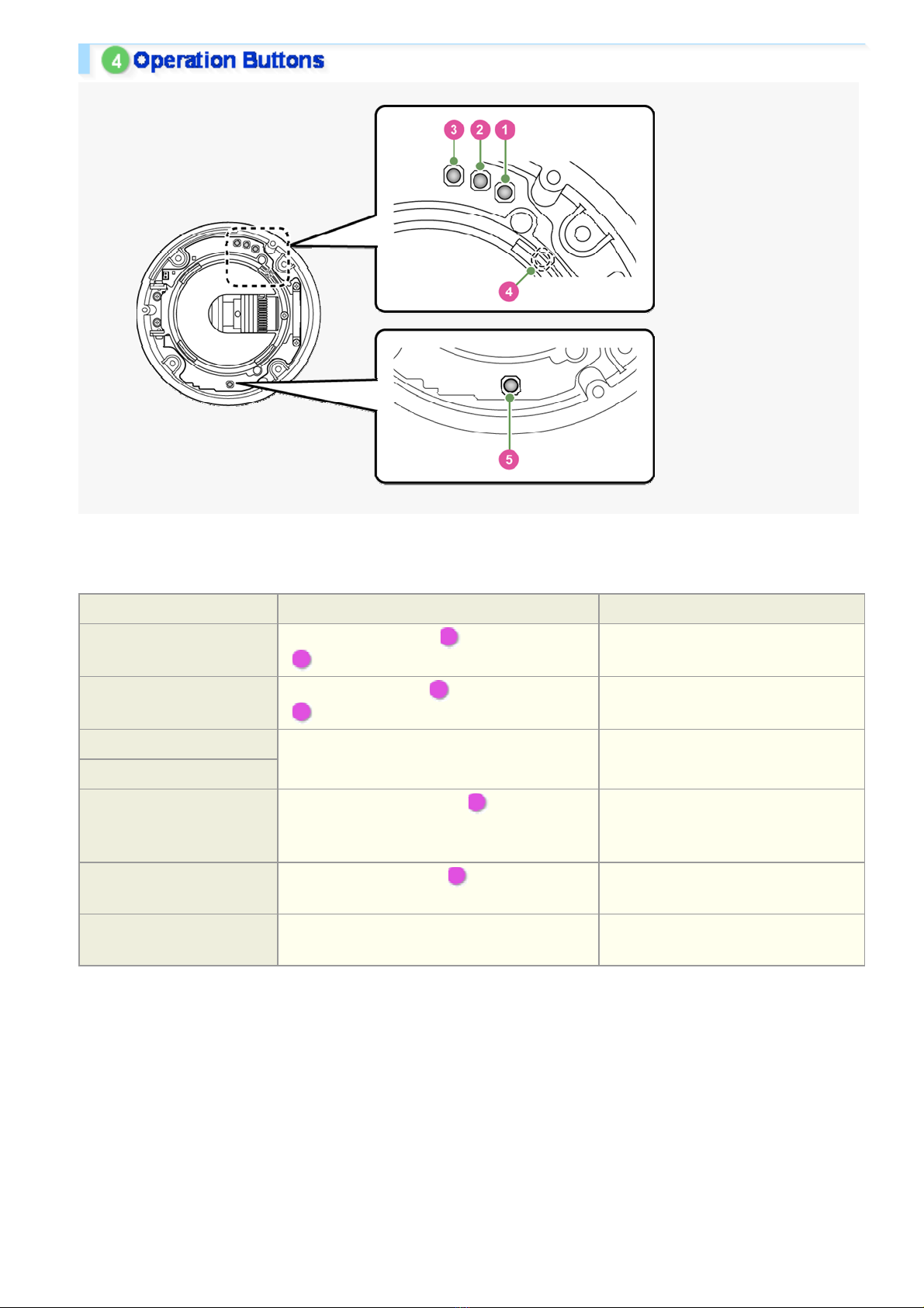
These buttons allow you to perform the following operati ons .
These operations may be performed with the Web browser install ed on you r PC. Fo r details, refer to the linked
information.
Operation Associated button and use Equivalent network operation screen
Restoring factory default
settings
Resetting login password
Adjusting focus
Adjusting iris
Inverting video of wall-
mounted camera
Restarting camera
Viewing Firmware Version
Press the NEAR button ( 1 ) and the SET button
( 3 ) simultaneously
Press the FAR button ( 2 ) and the SET button
( 3 ) simultaneously
For details, refer to th e “Lens Adjustment”
section.
Press the REVERSE button ( 4 ) Not supported via netwo rk operation
Press the RESET button ( 5 ) CAMERA SETTINGS (CAMERA
For details, refer to the “Viewing Firmware
Version” section.
OPTION SETTINGS (FACTORY
DEFAULT)
USER SETTINGS
CAMERA SETTINGS (FOCUS
ASSIST/IRIS SETTINGS)
For details, see the “Installation
Manual”.
REBOOT)
OPTION SETTINGS (FIRMWARE
UPDATE)
Introduction 6/15
Page 7
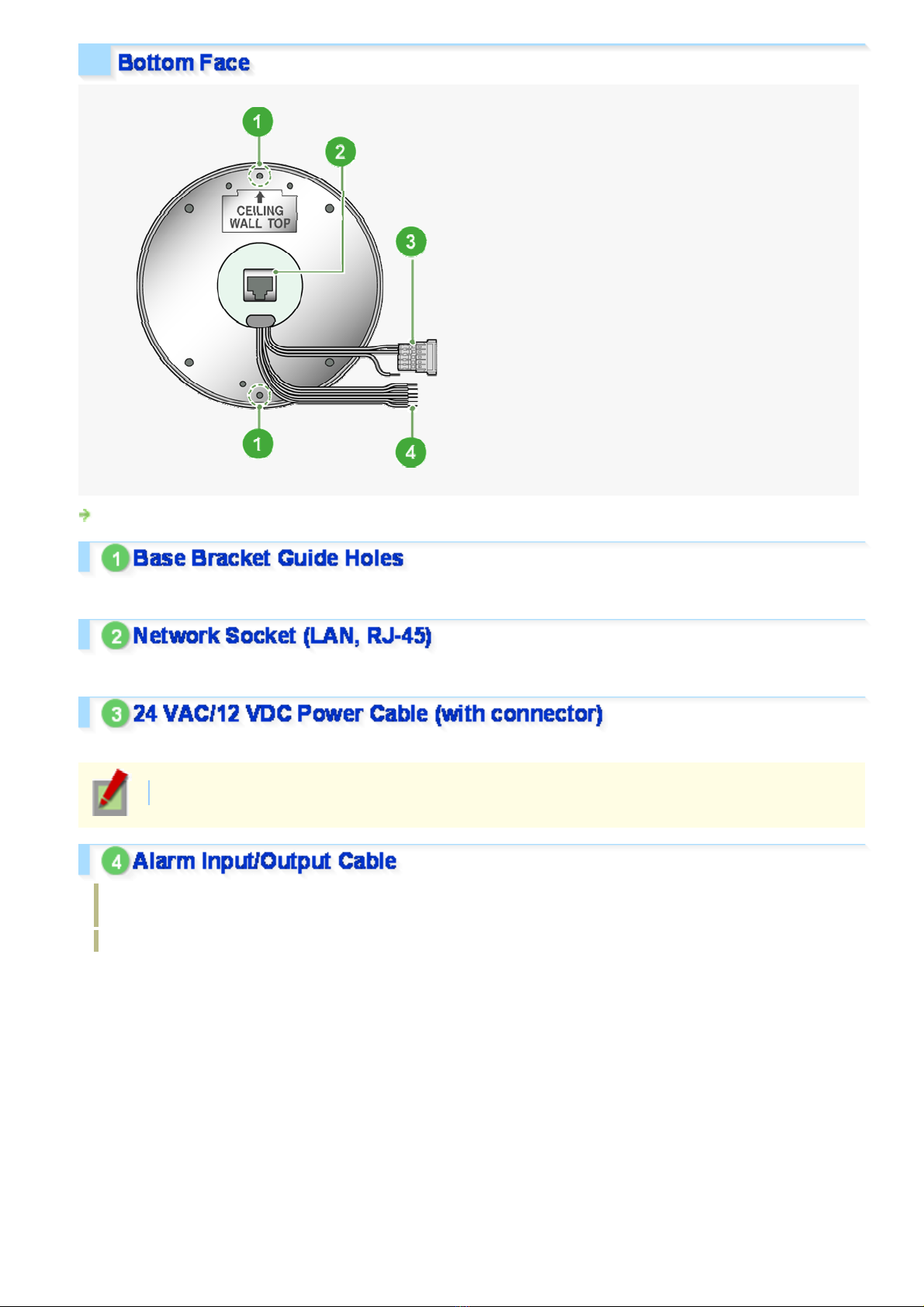
For the detailed procedures for c onnec ting terminals and cables, r efer to the “Connections” section.
Use these coupling holes to mount the camera to the separately-sold base bracket.
Use this socket to connect th e camera to your PC to enable net wor k oper ation.
Use this cable to connect a 24 VAC or 12 VDC power supply.
There is no power indicato r on the camera.
Alarm input cable: Connect an external switch, infrared sensor, or other device to detect alarm conditions
such as the entry of an intruder.
Alarm output cable: Connec t a buzzer, lamp, or other alarm device.
Introduction 7/15
Page 8
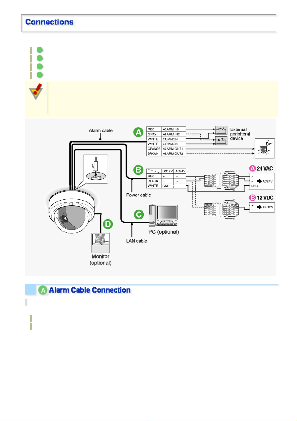
Perform the following connec tions according to the installation environmen t and application of your camera.
A Alarm Cable Connection
B Power Connection
C Network Connection
D Camera Monitor Connection
Before attempting the fo llowing connections, be sur e to turn of f all components of your system.
Improper connection may cause smoke or failures. Before at tempting to connect each system
component, carefully read the instruction manual th at com es with it to familiarize yourself with the
correct connection pr oc edur e.
Alarm Input Terminal Connection
Connect an alarm switch, infrar ed s ens or , or other device to detect alarm con ditions to the alarm input cable.
ALARM IN1: Red
ALARM IN2: gray
Introduction 8/15
Page 9
After connecting an alarm device, configure the input conditions for the corresponding alarm input
cable via network operation on the ALARM SETTINGS screen.
To use the alarm input cable as Day/Night switching signal path, follow the steps below.
( (This function is supported only by VDC-HD3300P/VDC-HD3300.))
Under [DAY/NIGHT], set [DAY/N IGHT] to “COLOR” and select the cable you want t o use in [EXT
ALARM].
On the ALARM SETTINGS screen, in [POLAR IT Y], selec t the signal polarity of the alarm input
terminal.
Connecting an external switch to ALARM IN1 allows you to set the system clock by operating the
switch. To set the system clock, configure the [CLOCK IN] setting on the CLOCK SETTINGS screen.
Alarm Output Terminal Connection
Connect a buzzer, lamp, or oth er alar m device to the alarm output cable.
ALARM OUT1: Orange
ALARM OUT2: Brown
After connecting an alar m devi ce , configure the output condit ions for the corresponding alarm output
cable via network operation on the ALARM SETTINGS screen.
Configuration of alarm output terminal is also possible via remote operation. For that, set [ALARM
OUT] to “REMOTE” on the ALARM SETTIN GS (ALARM OUT ) scre en.
Connect the power terminals (24 VAC/12 VDC) of the camera to a power supply.
A Connection to 24 VAC power supply
Although the power terminals have no polarity, the earth grou nding wir e m ust be connected to the GND (earth
grounding) terminal.
B Connection to 12 VDC power supply
Note the polarity (+/–) of the powe r ter minals when connecting the camera to a 12 VDC power supp ly .
Incorrect polarity may cause damage to the camera.
Be sure to use an 18AWG or thicker wire power cable.
A voltage drop may occur depending on the thickness of the power cable. If you must use a long
power cable, determine the cable type by ensuring that the volt age at t he 24- V AC/12- V DC term inals
is within the operating ran ge of th e camera.
When using PoE to power the camera, do not use th e camera' s power terminals.
This camera is designed so that you can use all of its functions via network operation.
By connecting the network (LAN) socket of the camera to your PC using a LAN cable, you can configure and
operate it from the Web browser ins talled on your PC.
Introduction 9/15
Page 10
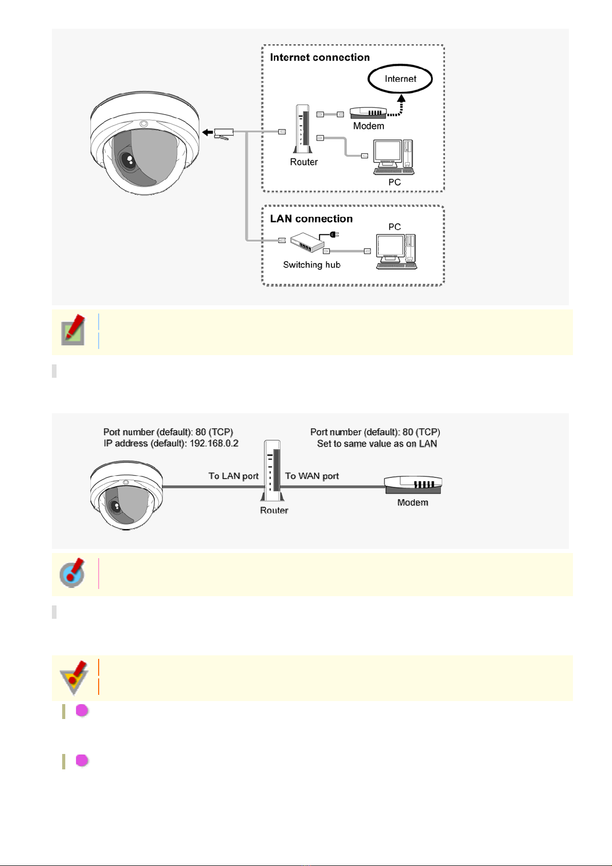
Use a LAN cable no longer than 100 m (109.4 yards) with the shield type CAT5 or higher.
The supported Web browser is Internet Explorer Ver.6.0 SP2 or higher, or Internet Explorer Ver.7.0.
About the internet connection
Port forwarding for the video por t must be enabled on the broadband rout er .
For details on how to set port forwa rd ing, please refer to your router ' s Ins truc tion manual.
To connect two or more cameras, on the NETWOR K SETTINGS s creen, assign them with port
numbers that are different from that of the first camera.
Using PoE
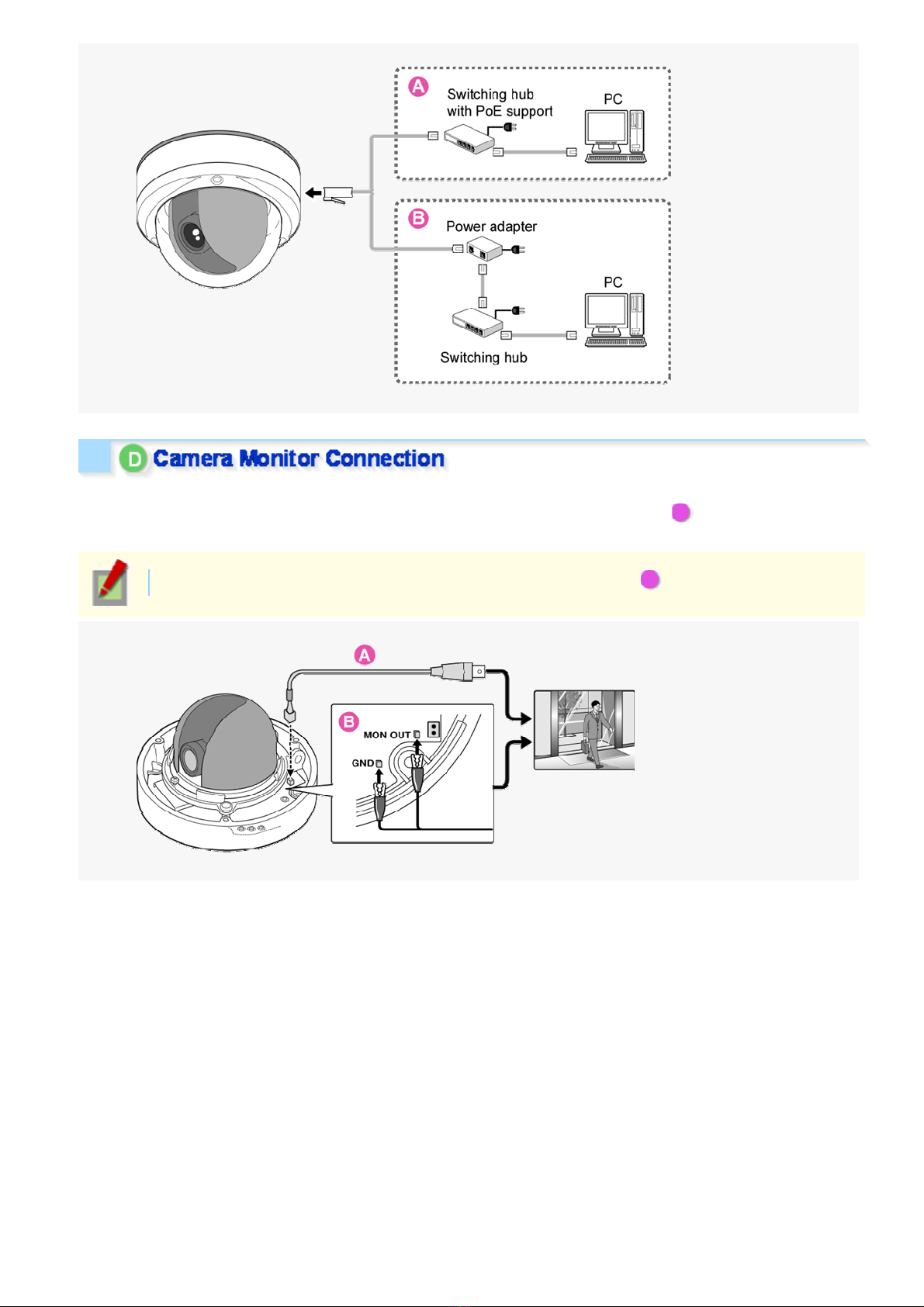
This camera supports PoE (Power over Ethernet). This means that you can install the camera in locations where
there is no 24-VAC/12-VDC power outlet nearby.
When using PoE to power the camera, do not use th e camera' s power terminals.
Do not power the PoE hub or PoE power adapter until y ou finish connecting the camera.
A Connecting the PC and camera through a switching hub
You can use a PoE-compatible switching hub to extend the transmission distance.
For details on the extendable distance, please refer to th e hub per form anc e in the specifications, etc .
B Connecting the PC and camera through a switching hub and a power adapter
Introduction 10/15
Page 11
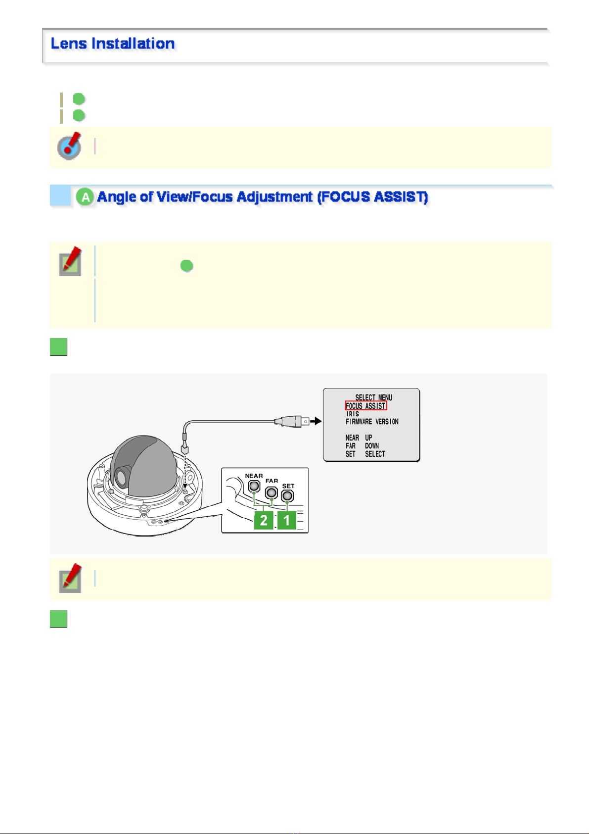
To perform focus adjustment with the camera, remove the dome cover, connect the supplied cable to the MON
OUT socket of the camera, and connec t a monitor to the camera using a video cable. ( A )
After adjustment, be sure t o remove the monitor cable.
You can use crocodile clip connectors instead of the supplied cable. ( B )
Introduction 11/15
Page 12
After installing the lens to th e camera, you need to perform the following adjustments for the lens.
A Angle of View/Focus Adjustment (FOCUS ASSIST)
B Iris Adjustment (IRIS)
Using network operation, you can use the focus assist funct ion to adjust the focus.
Use the focus assist function to accurately focus on subject in high-resolution megapixel image because otherwise
doing so would be extremely difficult.
When focus cannot be adjusted normally because the video images are too dark or too bright, adjust
the lens iris first ( B ).
The focus must be readjusted if the camera has lost focus due to difference in the subject distance or
ambient temperature, the deterioration of the lens and ins tallation environm ent, and the like that have
been caused over the years.
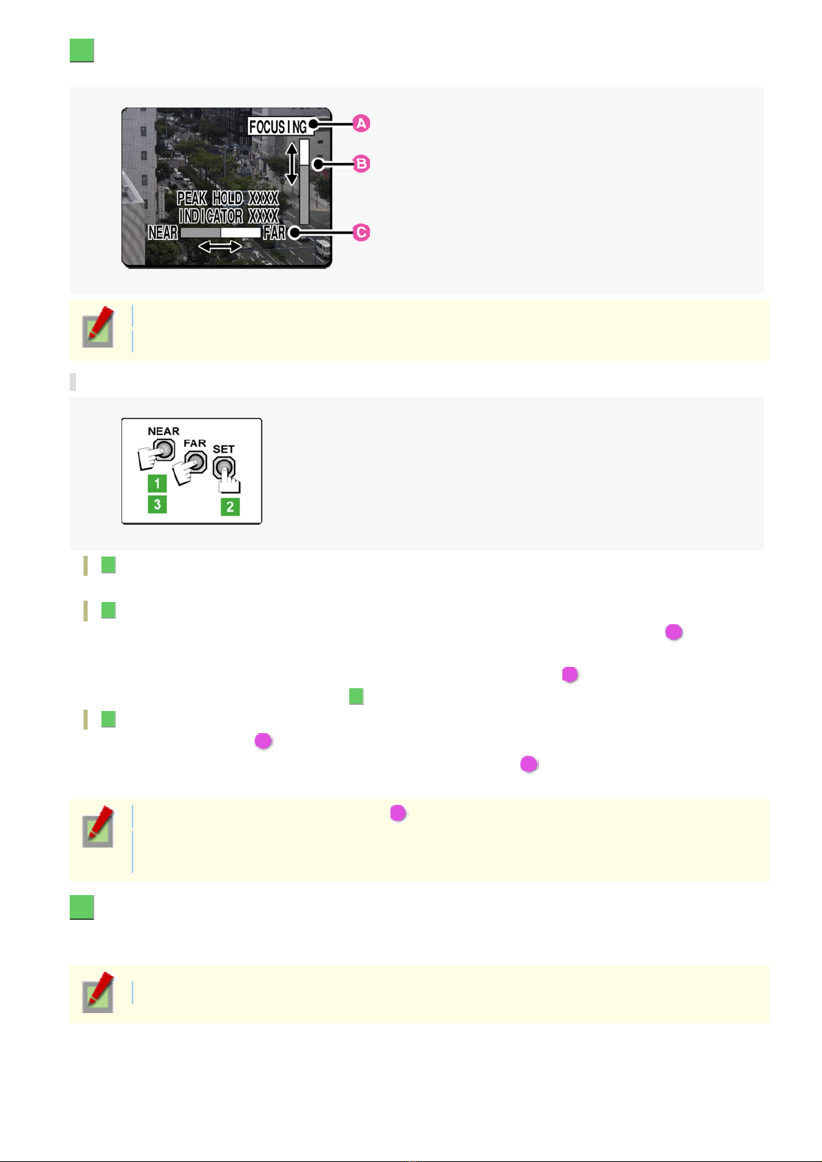
1 Press the SET button for 2 seconds or more.
The monitor now shows the SELECT MENU screen.
On the SELECT MENU screen, all information is displayed in English.
2 Select [FOCUS ASSIST] using the NEAR/FAR button and press the SET button.
The monitor now shows the focus adj us tment screen.
Introduction 12/15
Page 13
3 Adjust the lens orientation. Then adjust angle of view using the zoom ring, and the focus
using the buttons.
PEAK HOLD: Shows the value of the maximum focus level.
INDICATOR: Shows the value of the current focus level.
Adjusting focus
1 Use the NEAR/FAR button to roughly focus on the subject.
Adjust by monitoring t he vid eo ima ge on the monitor.
2 Press the SET button.
The camera automatically foc us es on the subject. Note that the color of the status indic ator ( A )
“FOCUSING” turns from black to orange.
If the camera fails to automatically focus on the object, the status indicator ( A ) will indicate “ERROR”. In this
case, manually adjust the focus (in Step 3 ).
3 Press the NEAR/FAR button to adjust the focus.
Adjust to set th e FA ba r ( B ) t o the maxi mum level.
When the subject comes into focus, the color of the status indicator ( A ) “FOCUSING” turns from black to
orange.
Pressing the button causes the FB bar ( C ) gauge to move.
The position changes step by step each time the button is pressed and continuously at a high speed
when the button is held down.
4 Press the SET button for 2 seconds or more.
The focus adjustment screen will close.
The focus adjustment screen will also close automatically if left idle for 5 minutes or more.
If video is out of focus in either colo r or black - and- white mode, adjust the focus in re sp ec tive m odes .
Introduction 13/15
Page 14
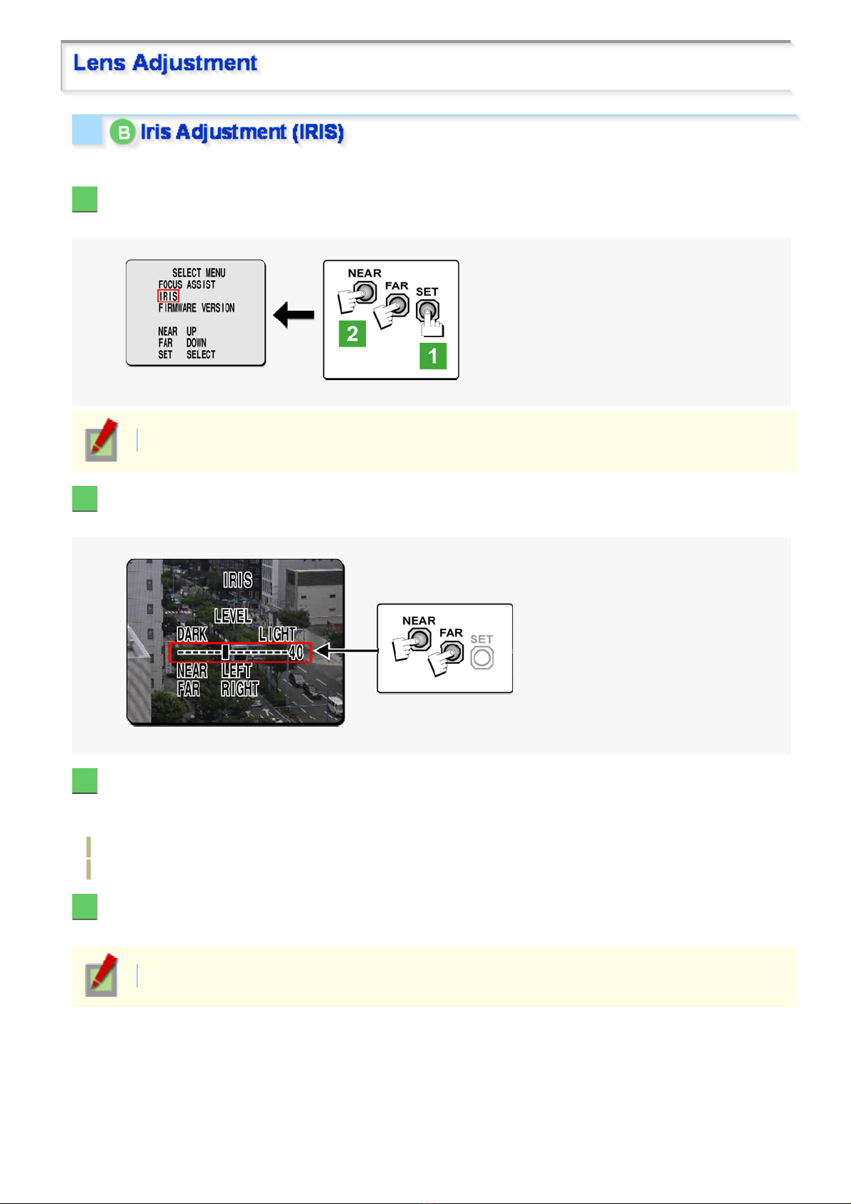
If the camera produces too dark, too bright, or other incorre ct vi deo images, adjust the lens iris.
1 Press the SET button for 2 seconds or more.
The monitor now shows the SELECT MENU screen.
On the SELECT MENU screen, all information is displayed in English.
2 Select [IRIS] using the NEAR/FAR button and press the SET button.
The monitor now shows the iris adjustment screen.
3 Press the NEAR/FAR button to adjust the iris level.
The position changes step by step eac h time the button is pressed and continu ous ly at a high speed when the
button is held down.
NEAR: Closes the iris to produce darker images.
FAR: Opens the iris to produce brighter images.
4 Press the SET button for 2 seconds or more.
The iris adjustment screen will be closed.
The iris adjustment screen will also close automatically if left idle for 5 minutes or more.
Introduction 14/15
Page 15
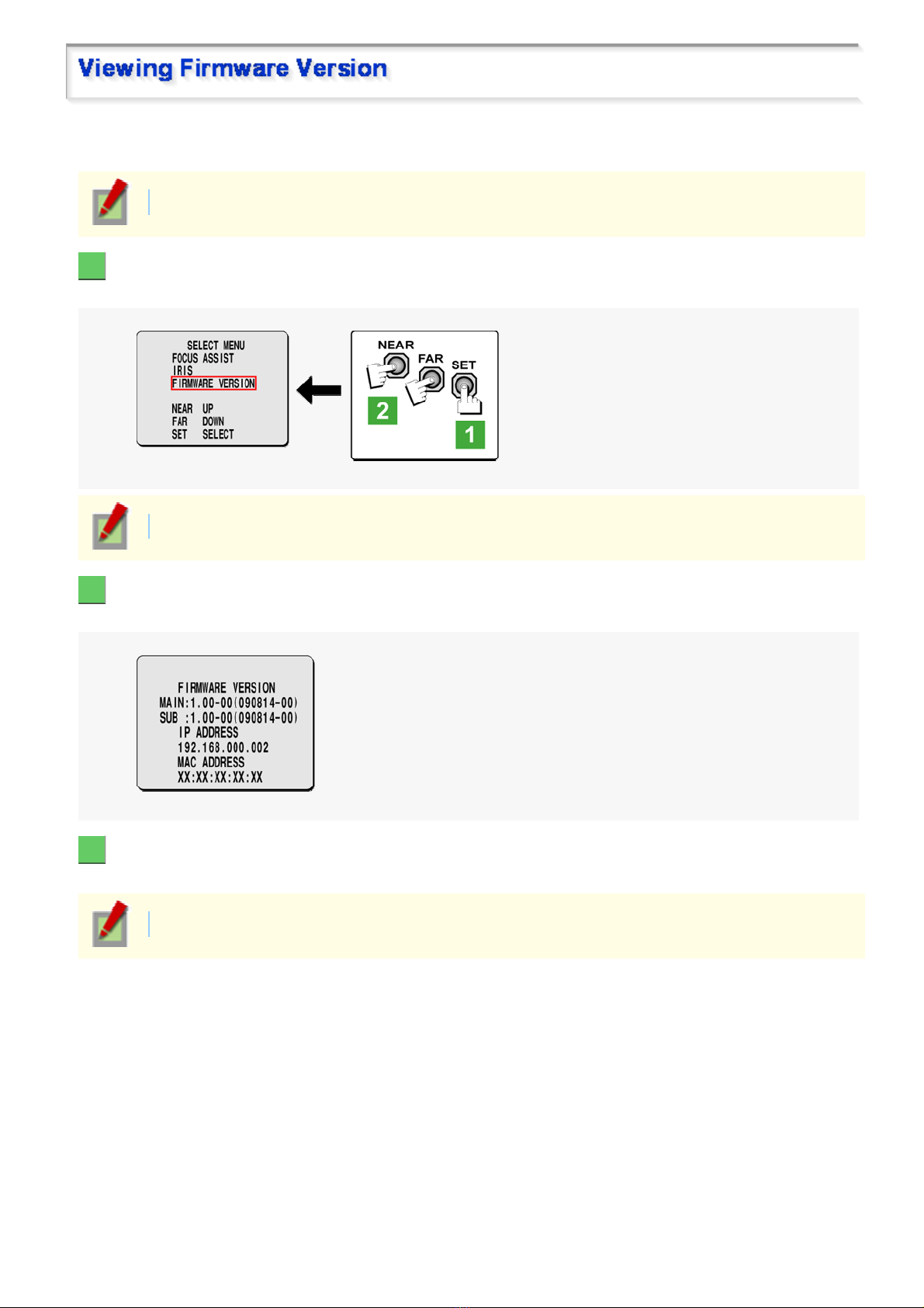
On the FIRMWARE VERSION screen, you can chec k the firmw ar e v er s ion, IP address, and other information on
the camera.
The firmware version can also be checked via network operation on the OPTION SETTINGS screen.
1 Press the SET button for 2 seconds or more.
The monitor now shows the SELECT MENU screen.
On the SELECT MENU screen, all information is displayed in English.
2 Select [FIRMWARE VERSION] using the NEAR/FAR button and press the SET button.
The monitor now shows the FIRMWARE VERSION screen.
3 Press the SET button for 2 seconds or more.
The FIRMWARE VERSION screen closes.
The FIRMWARE VERSION screen will close automatically if left idle for 5 minutes or more.
Introduction 15/15
Page 16
VDC-HD3300/HD300P
VDC-HD3100/HD3100P
From Connection to Network Operation
Live V ideo M onit oring
Alarm Detection and Output
Software Infor mation
Configuration menu quick reference tables
Quick Operation Guide1/10
Page 17
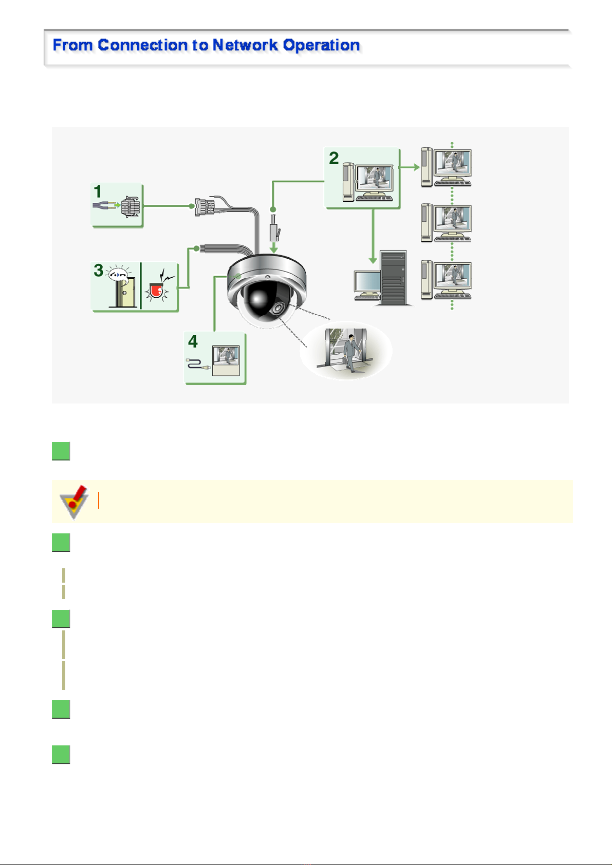
Follow the steps below to set up and connec t th e camera to your PC.
You can use alarm video recording, bidirectional audio communications, and other s tandard features of the
camera, in addition to normal liv e video monitoring.
1 Connect the power cable to the power terminals.
Use a 24-VAC or 12-VDC power supply.
Do not turn on the camera until you complete all c onnec tions.
2 Connect the network (LAN) socket to your PC using a LAN cable.
Check the operating environment of your PC and perform the following operations:
Check the network information on your PC.
Install the “H.264 Plug-in” from the supplied CD-ROM onto your PC.
3 Connect necessary external devices to the alarm input/output terminals.
ALARM IN1/2 terminal: Connect an external switch, infrared sensor, or other device to detect alarm
conditions such as entry of an int r uder .
ALARM OUT 1/2: Connect a buzzer, lamp , or other alar m dev ic e to out put a signal to warn people of the
occurrence of an alarm condition.
4 Connect a monitor for focus adjustment to the monitor output socket.
Connect your monitor to the camera via the supp lied v ideo cable.
5 Turn on the camera.
Live video appears on the monitor.
Quick Operation Guide 2/10
Page 18

To enable surveillanc e with clear video images, adjust the lens focus while viewing the subject on the
FOCUS ASSIST screen displayed on the monitor.
After adjustment, be sure to remove the monitor cable.
6 Access the camera from your PC's Web browser.
Live video appears on the live s creen. Now, you can perform all network operations from your PC.
Quick Operation Guide 3/10
Page 19
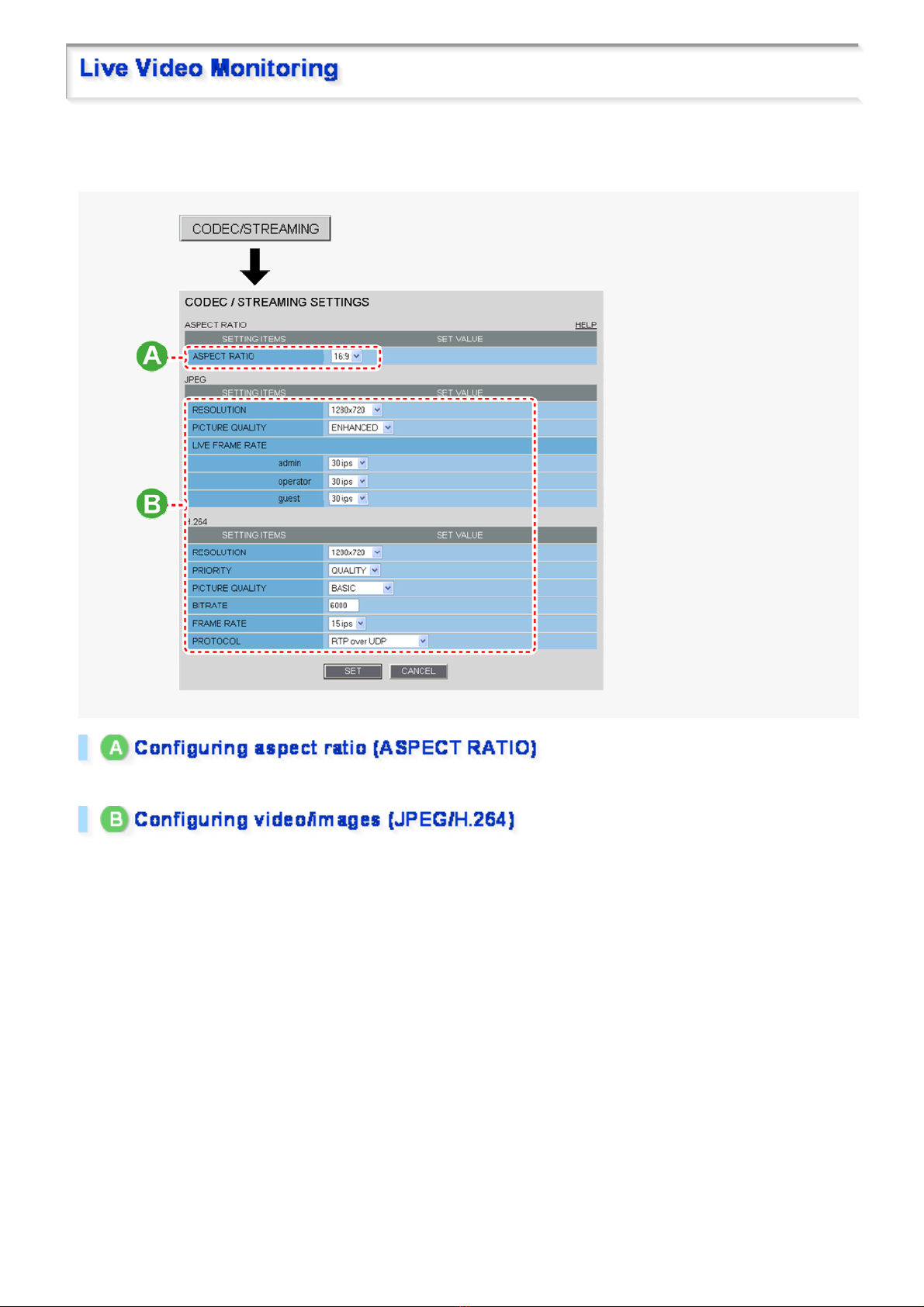
If you are operating the camer a for the first time, check the factor y default video/image condition s on the
CODEC/STREAMING SETTINGS scr een. Change the default setting s as neces s ar y.
For details, refer to the “CODEC/STREAMING SETTINGS” section.
16:9 (Default) → 4:3
You can switch between JPEG image and H.264 video us ing the buttons on the live screen control panel.
The screenshot above shows the factory default settings for each video/image condition.
Quick Operation Guide 4/10
Page 20
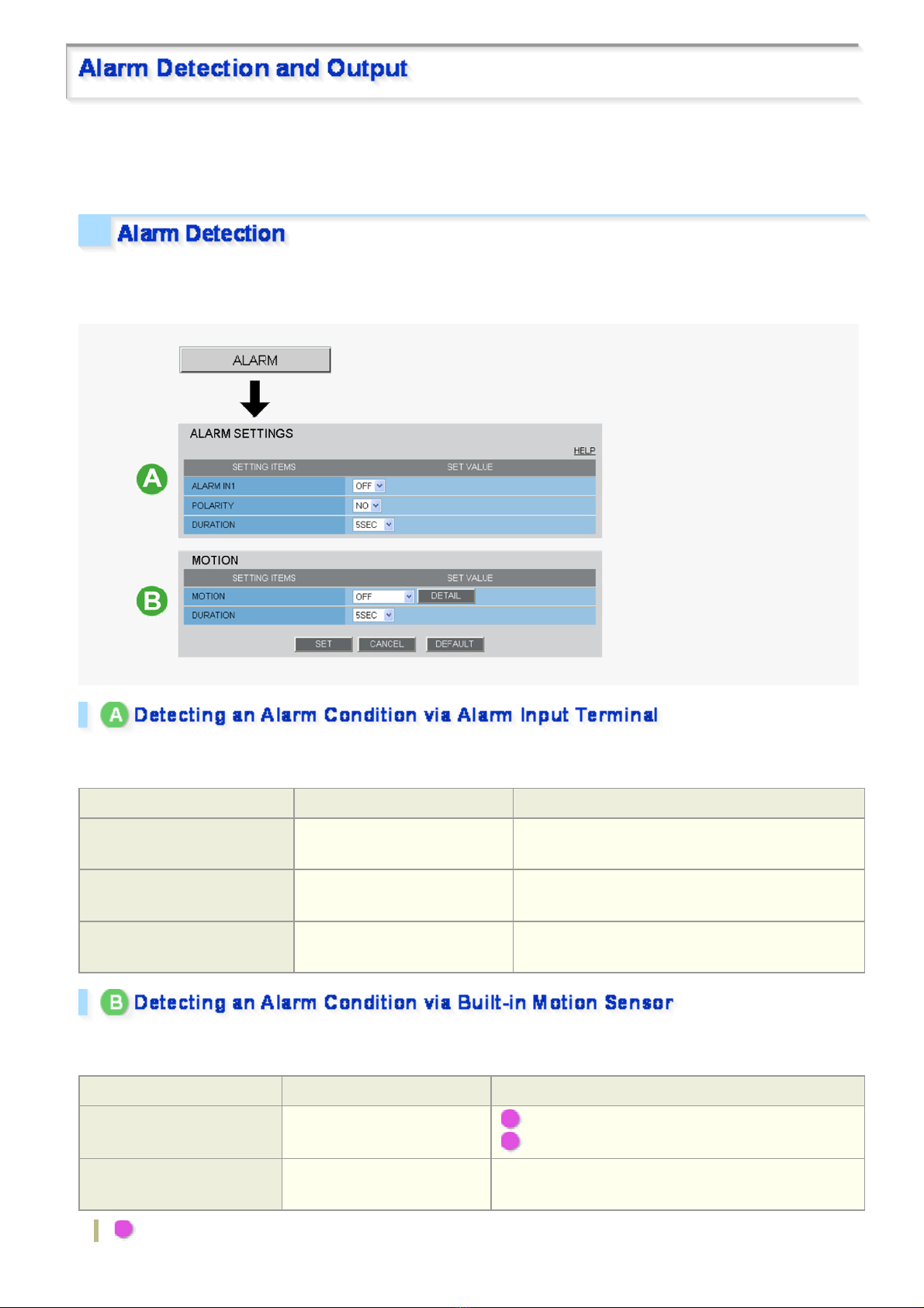
If you are operating the camer a for the first time, check the factor y default alarm detection conditions on the
ALARM SETTINGS screen. Change the defaul t sett ings as des ir ed.
For details, refer to the “ALARM SETTINGS” section.
You can configure the camera to detect alarm conditions via the “alarm input terminals” or “built-in motion sensor”.
For how to configure the camera to dete ct alar m conditions via the alarm input term inals , refer to the “Alarm
Input/Output Terminal Connections” section.
Connecting an alarm swit ch , inf r ar ed se ns or , or other ex ternal device to the ALARM IN1/2 terminal enables the
camera to detect alarm conditions such as entry of an intruder.
Setting Item Default Setting Optional Setting
ALARM IN1/2 (Alarm input
terminal number)
POLARITY (Signal polarity)
DURATION (Alarm retention
duration)
OFF (Disables alarm detection.) ON (Enables alarm detection.)
NO (Ex.: Detects an alarm when
door is closed)
5SEC (Ex.: Records alarm video
for 5 sec.)
NC (Ex.: Detects an alarm when door is opened.)
10SEC to 5MIN, CC (Retains the alarm state as long
as the alarm signal persists.)
The camera uses the built-in motion sensor to detect alarm conditions.
The motion sensor detects an alarm condition in two ways as follows.
Setting Item Default Setting Optional Setting
MOTION (Use of built-in
motion sensor)
DURATION (Alarm retention
duration)
OFF (Disables alarm
detection.)
5SEC (Ex.: Records alarm
video for 5 sec.)
A MASKING
B DETECT
10SEC to 5MIN, CC (Retains an alarm state as long as
the motion alarm persists.)
A Disabling motion detect i on in ma sked areas
Quick Operation Guide 5/10
Page 21
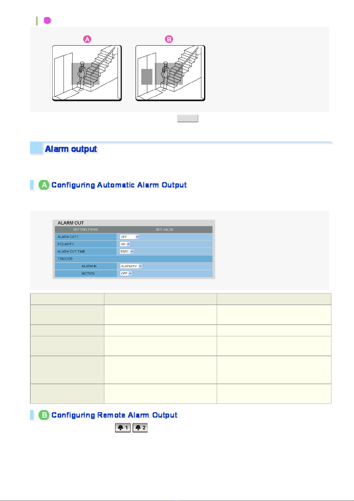
B Detecting motion in specific areas
In [MOT IO N] , a fte r se l ecting a mot io n se nsor type, cli ck DETAIL to configure the detection conditions on the
detailed configuration screen.
You can configure the camera to “automatically output alarm signals” or “remotely (manually) output alarm
signals”.
You can configure the camera to auto ma tically output an alarm signal when either of its alarm input termina ls
receives an alarm signal.
Setting Item Default Setting Optional Setting
ALARM OUT1/ 2 (Alarm
output terminal number)
POLARITY (Signal polarity) NO NC
ALARM OUT TIME (Alarm
output time)
ALARM IN (Output
condition)
OFF (Disables alarm output.) ON (Enables automatic alarm output.)
5SEC (Ex.: Beeps a warning for 5 sec.) 10SEC to 5MIN
ALARM IN1 (Triggers alarm output when
ALARM IN1 terminal receives an alarm
signal.)
ALARM IN2 (Triggers alarm output when
ALARM IN2 terminal receives an alarm
signal.)
MOTION (Output condition)
OFF (Disables alarm output usi ng m otion
sensor.)
ON (Triggers alarm output usi ng m oti on
sensor.)
Use the Remote Alarm buttons ( ) provided on the live screen t o send alar m signals from the camera's
alarm output terminals .
Quick Operation Guide 6/10
Page 22

Setting Item Default Setting Optional Setting
ALARM OUT1/ 2 (Alarm output
terminal number)
POLARITY (Signal polarity) NO NC
ALARM OUT TIME (Alarm output
time)
OFF (Disables alarm
output.)
5SEC (Ex.: Beeps a warning
for 5 sec.)
REMOTE (Enables remote alarm output.)
10SEC to 5MIN, CC (Stops alarm output when
Remote Alarm button is clicked.)
Quick Operation Guide 7/10
Page 23
You can install the following softwar e on you r PC to extend the capabilities of your surveillance system .
The CD-ROM that comes with the camera includes all the supplied software.
A H.264 Plug-in (Plug-in for monitoring live video as high-quality moving images)
This plug-in software is required to display H.264 video on the live screen. Be sure to install it on each computer
from which you access the camera via network operation.
B VA-SW3050Lite (Application for monitoring live video from more than one camera)
This monitoring application is designed for use with SANYO network cameras.
You can access up to 128 cameras simultaneously.
The application lets you monitor video images from connecte d cameras in either the single screen or the 4-
screen, 9- screen, or 16-split s c r een m ode.
C Auto IP Setup (Utility for automatically setting up IP addresses when two or more new
cameras are connected)
This utility automatically assigns a unique IP address to each camera that has the factory default IP address
(“192.168.0.2”).
Using the utility's camera search function, you can che ck th e IP addr es se s of al l cameras ex is ting on the
same local network.
It is also possible to check and correct overlapping IP addresses.
VA-SW3050Server/Client (Application for recording and playing back streaming images from
camera)
This recorder/pla ye r appl ic ation is designed for use with SANYO network camer as .
This is a complete version of the VA-SW3 050 se r ies sof tware, which offers all the functions you need to
perform monitoring, recording, search, playback, and other operations in a surveillance system.
This software requir es at least two PCs that serve as the server and the client.
Quick Operation Guide 8/10
Page 24
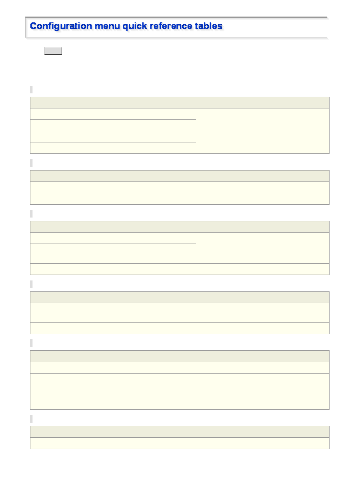
Click ME NU on the control panel to display the admi nistrator configuration menu that includes a series of menu
selection buttons .
If you are a surveillance system administrator, use t h ese buttons to conf igure necessary settings according to the
installation environment and application of your camera.
Configuration Related to Network Connection
Operation Configuration Screen (Menu)
Changing the camera's IP address. NETWORK SETTINGS
Using SANYO's DDNS service.
Using SSL communicati on.
Streaming H.264 video in multicast
Clock and Camera Title Configuration
Operation Configuration Screen (Menu)
Adjusting clock to specific time based on external input signal CLOCK SETTINGS
Configuring the camera ti tle
Configuration Related to Access and Security
Operation Configuration Screen (Menu)
Changing the user password USER SETTINGS
Allowing all users to access the camera without any authentication
check
Restricting PCs that have access to the camera SECURITY SETTINGS
Configuration Related to Live Video
Operation Configuration Screen (Menu)
Accessing the camer a from video viewer or similar software to view
live video
Hiding specific portions of video CAMERA SETTINGS (PRIVACY MASK)
NETWORK SETTINGS
Alarm-Related Configuration
Operation Configuration Screen (Menu)
Sending an alarm image via e-mail E-MAIL SETTINGS
Using the alarm input terminals to switch the camera between the
color and black-and-white video modes
( (This function is supported only by VDC-HD3300P/VDCHD3300.))
CAMERA SETTINGS (DAY/NIGHT)
Recording-Related Configuration
Operation Configuration Screen (Menu)
Recording images from the camera to an FTP server FTP SETTINGS
Quick Operation Guide 9/10
Page 25

Optional Configuration
Operation Configuration Screen (Menu)
Updating the camera's firmwar e to the lat est version. OPTION SETTINGS (FIRMWARE UPDATE)
Restoring the factory default settings OPTION SETTINGS (FACTORY DEFAULT)
Backing up or uploading settings OPTION SETTINGS (MENU BACKUP/MENU
UPLOAD)
Viewing the access log, system log, and operation log OPTION SETTINGS (LOG)
Quick Operation Guide 10/10
Page 26
VDC-HD3300/HD300P
B
VDC-HD3100/HD3100P
Preparing Your Computer for Network Operation
Setting Up IP Addresses Automatically (Auto IP Setup)
Checking the operating environment
Configue the network information on your PC
Operation Privileges and Login Users
efore You Begin Network Operation1/13
Page 27
Follow the steps below to prepare your computer for network operat ion. For detailed procedure, refer to the linked
B
information.
1 Assign a unique IP address to each camera.
If you have newly installed two or more cameras on your network, you can accomplish this by using the supplied
“Auto IP Setu p ” so ftware.
2 Check your operating environment
3 Connect the camera to the network to which your PC is also connected.
4 Configue the network information on your PC
You need to configure information such as the IP address of your PC.
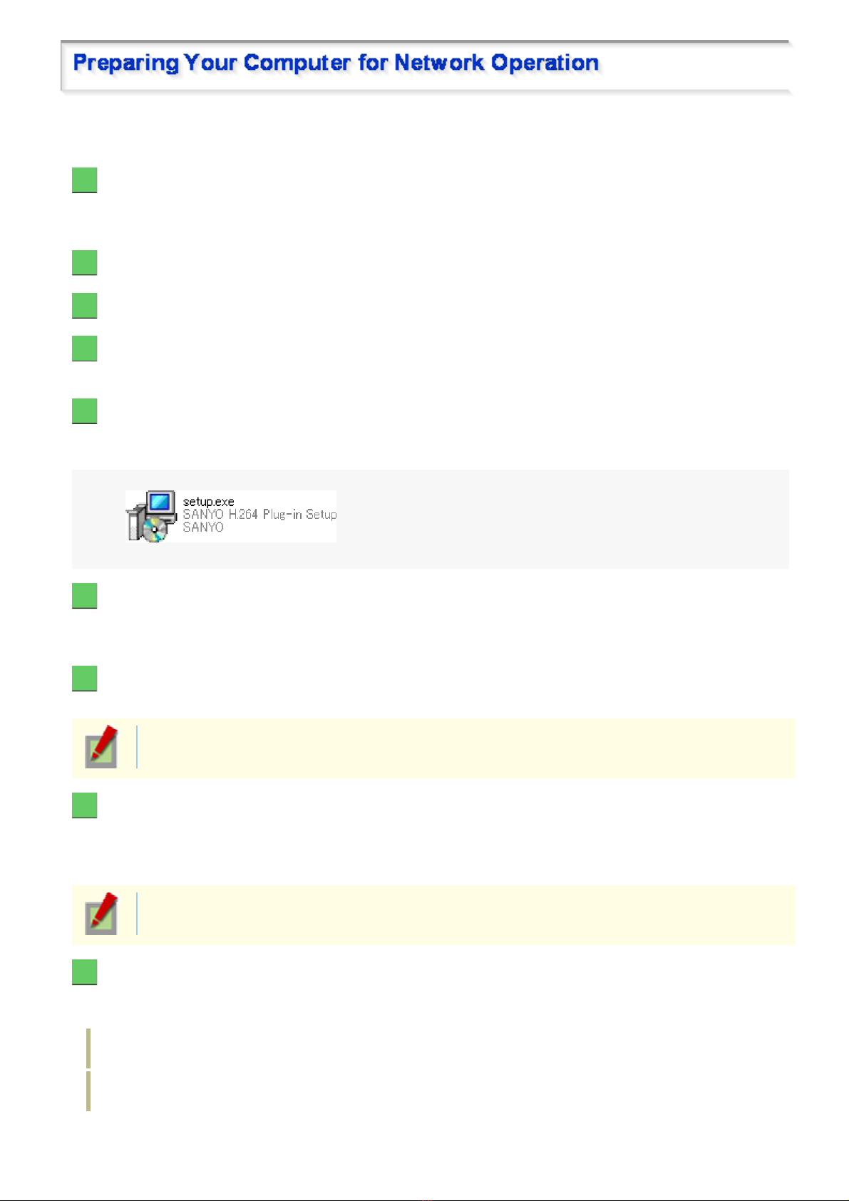
5 Install the “H.264 Plug-in” from the supplied CD-ROM onto your PC.
Double-click the “setup.exe” icon and complete the steps in the wizard.
You are now ready to monitor the surveillance video in the H.264 format.
6 Access the camera from your Web browser.
From your Web browser (Internet Explorer), access the camera and log into the system as an “admin” user
(administrator).
7 Monitor live video.
When you access the camera and log int o the syst em , live v ideo from the camera appears on the live screen.
If the live screen displ ay s no or distorted video, check your operating environment and connection
conditions.
8 Configure the necessary settings on the administrator configuration screens.
Although the camera is already c onfigured with the factory defa ult settings so that you can monitor live v ideo
immediately after y ou log into the system, you need to configure necess ar y set tings according to your inst allation
environment and application of the camera.
If this is the first access to the camer a, start by configuring the system cl oc k on the CLOCK
SETTINGS scree n .
9 Use associated software applications to extend the capabilities of your surveillance
system.
Install the following associated software applications on your PC, as required:
VA-SW3050Lite (supplied): Monitor application for monitoring video images from more than one camera
simultaneously on a multi-vi ew screen.
VA-SW3050Server/Client (optional): Recorder/player application for recording and playing bac k stre ami ng
video data from the network.
efore You Begin Network Operation 2/13
Page 28
If you are installing two or more new cameras on the same local network, you need to change the factory default
B
IP address of each camera to prevent IP address overlap. The suppl ied “Auto IP Setup ” s oftware frees you from
this burden by automatic ally as s igning a unique IP address to each camera on your network.
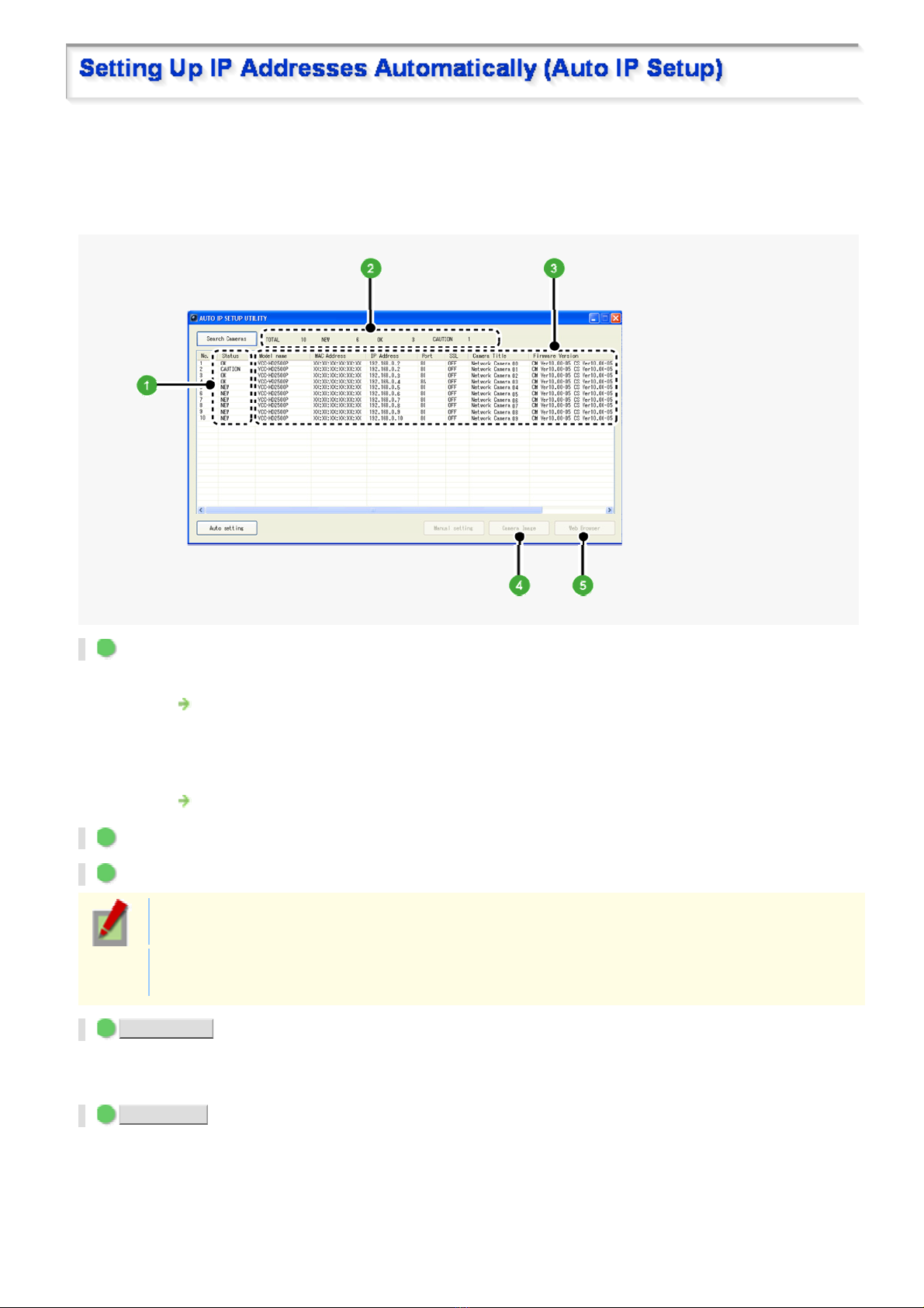
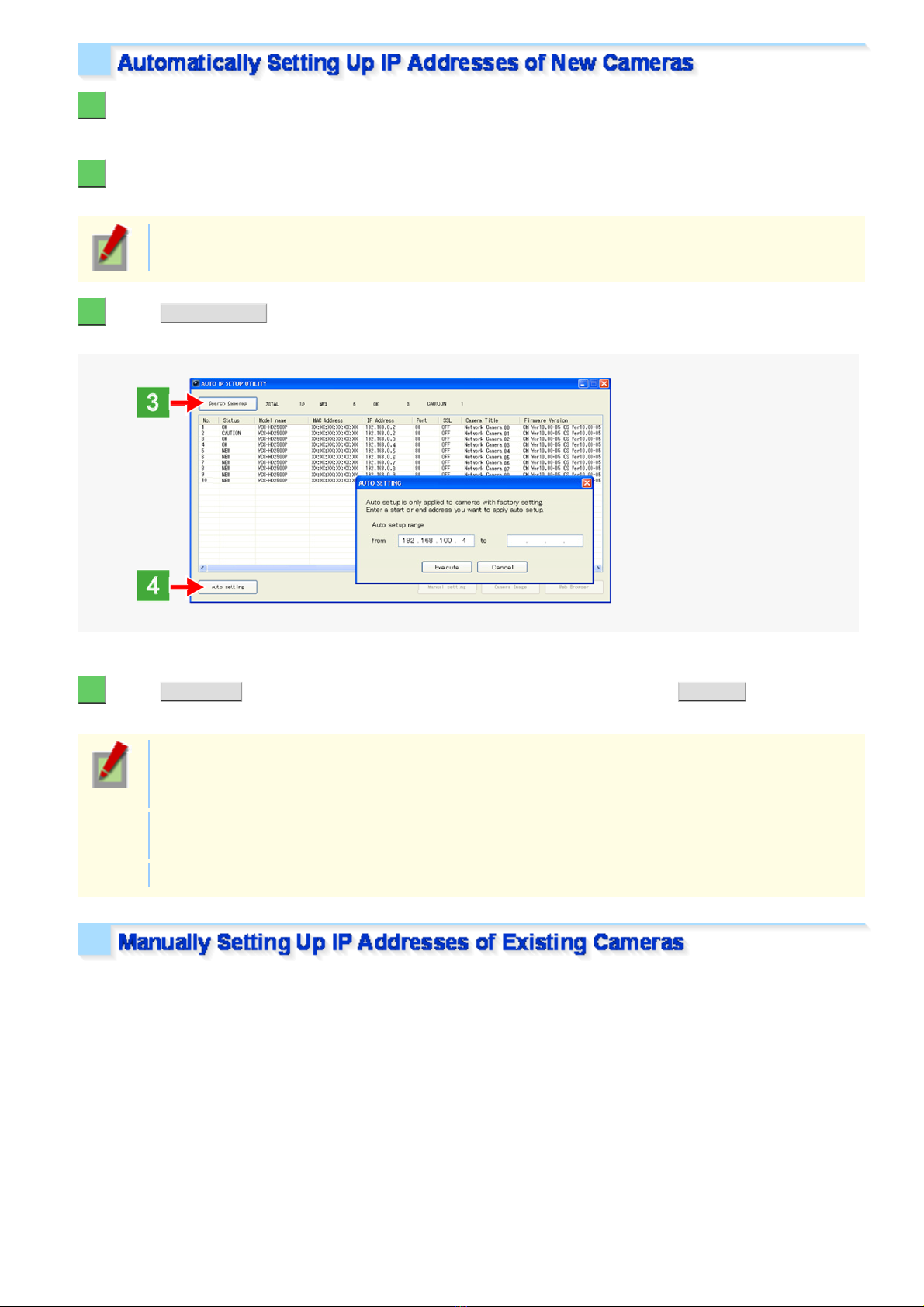
Before setting up the IP addresses automatically, click the [Search Cameras] button in the utilit y window to search
all cameras on the network and dis play the address settings and detail s of eac h camer a.
1 Status
NEW: The camera has the default IP address (“192.168.0.2”).
Assign a unique IP address.
OK: The camera has a unique IP address and can be conn ec ted successfully to network.
CAUTION: The camera cannot be connected succ es s fully to the network because of IP address overlap or
other reason.
Change the IP address.
2 Number of searched cameras (Total and by status)
3 Camera details
“Model name”, “IP Address ” , “Po rt” , “S SL ”, “Camera Title”, and “Firmware V er s ion” ar e not shown if
the network board or other hard war e is not sup ported.
“IP Address”, “Port”, “SSL”, and “Camera Title” are editable. (Refer to the “Manually Setting Up IP
Addresses of Existing Camera s” sectio n.)
4 Camera Image button
Select the desired camera row and click this button. Then, video from the camera appears in a separate window.
Use it to check which camera is select ed or wh en editing the camera title or other data.
5 Web Browser button
Select the desired camer a ro w and cli ck th is butt on. Then, the Web browser opens and connect s to the camer a
automatically.
efore You Begin Network Operation 3/13
Page 29
1 Insert the supplied CD-ROM into the CD-ROM drive of your PC.
B
The opening menu appears.
2 Click [Auto IP Setup].
The utility window opens so that you c an sea rch cameras.
If you encounter a firewall confirmation dialog box, disable the firewall so that your PC can
communicate with the camera.
3 Click Search Cameras .
The utility searches all ca meras on the local network and shows informatio n on each camera one aft er another.
The above screenshot shows an example when your PC is connected to 10 cameras.
4 Click Auto setting and, in the address range selection dialog box, click EXECUTE .
The utility automatically assigns a series of new IP addresses , starting from the start addr es s .
The dialog box initially shows, as the start IP address, the IP address to be assigned to the first
camera that has a status of “NEW”.
To specify your own address range, type both the start and end IP address es .
The utility automatically assigns an IP address to each camera located in the LAN, but not beyond
the router.
It skips any IP address that is alr eady us ed.
If you find that the searched ca meras have overlapping IP addresses (i ndicated by a status of “CAUTION”) or if
you need to change a camera title , you can edit th e dis play ed c am er a data manually as described below.
efore You Begin Network Operation 4/13
Page 30
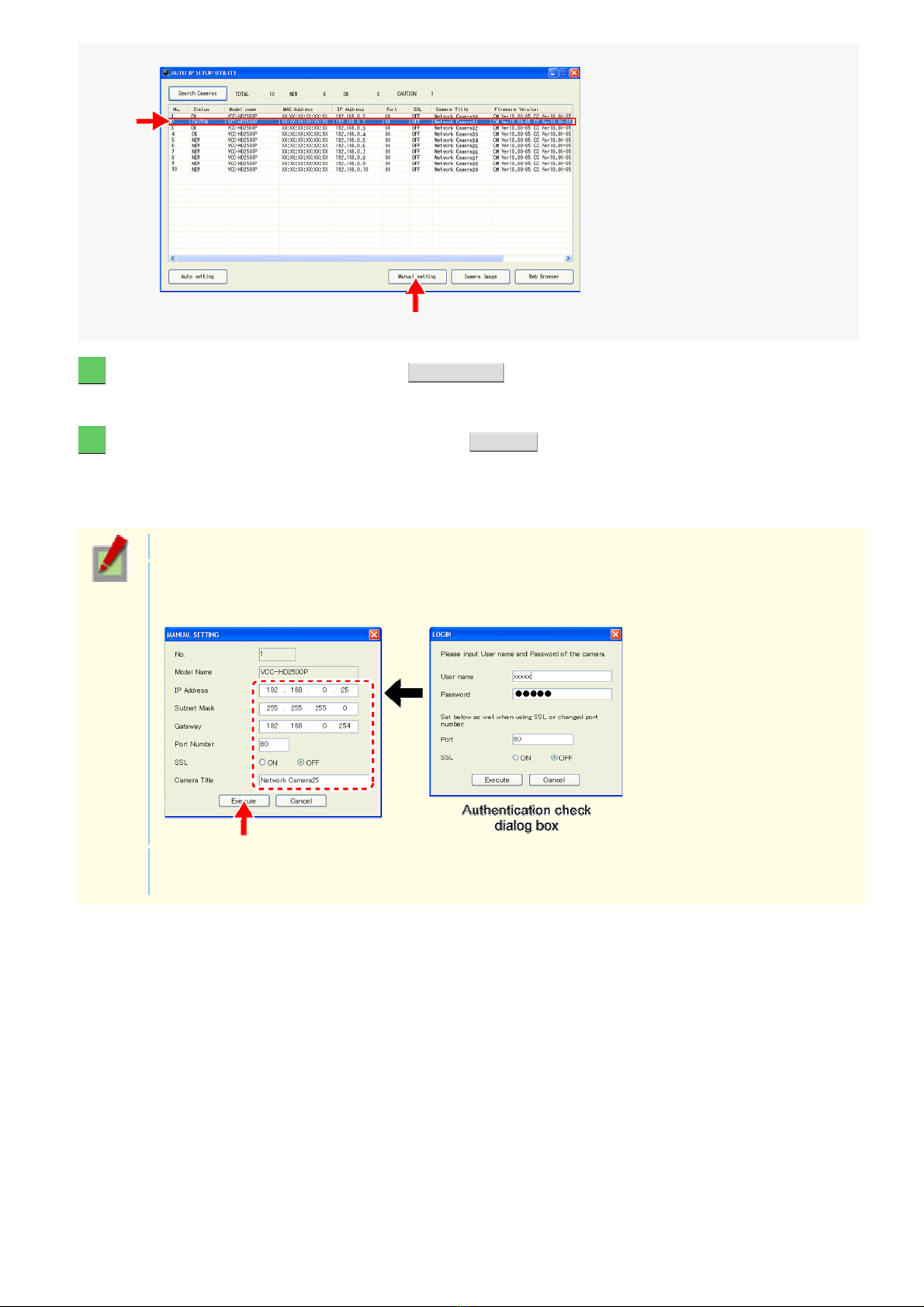
1 Select the desired camera and click Manual setting .
B
The camera information dialog box opens.
2 Make changes to the camera data and click EXECUTE .
This transmits your cha nges to th e camera.
You can see the problem of IP address over lap has been r es olv ed in the [Status] row of the list, which has been
changed from “CAUTION” to “OK”.
You cannot change the model name.
If your login user name and passwo rd has been chang ed from the fa ctor y default settings, you will be
presented with an authentication check dialog box . In this case, type the current user name and
password.
If SSL communication is enabled for the selected camera, you cann ot edit the camera data. Change
the SSL and port number settings in the authentication check dialog box.
efore You Begin Network Operation 5/13
Page 31

To operate the camera via networ k oper ation, you must meet the following operat ing requirements.
B
PC:
Operating system:
CPU:
Memory:
IBM PC/AT compatible
Windows XP Professional/Windows Vista
Core2Duo E6700 2.66 GH z or higher
Windows XP: 1GB or more
Windows Vista: 2GB or more
Network interface:
Display card:
Graphics chip:
10BASE-T/100BASE-TX (RJ-45 connector)
1920×1200 pixels or higher
ATI RADEON HD2600 series or higher
nVIDIA GeForce 8600 series or higher
nVIDIA Quadro FX550 ser ies or higher
Web browser:
Internet Explorer Ver. 6.0 SP2 or high er , or Internet Explorer V er . 7. 0
Use a LAN cable no longer than 100 m (109.4 yards) with the shield type CAT5 or higher.
The live video may be delayed depending on your system environment.
Use Windows Update to keep the operating system and browser up-to-date.
Note, however, that Inter net Explorer 8 is not supported.
In the cases below, configure the Internet Explorer's settings by clicking [Tool] and then [Internet Options].
When accessing the camera using SSL encryption for video signal transmission
1 Click the [Ad va nc ed] t ab.
2 Make sure that th e [Use SSL 2. 0] and [ Use SSL 3.0] che ck boxes under [Security] are selec ted. If
deselected, selec t t hem .
When the video refresh is unstable
1 Click the [General] tab.
2 Under [Temporary Internet Files], click [Settings].
For Windows Vista, clic k [Settings] under [Browsing history].
3 Set the slider under [Amount of disk space to use:] to a low value (the minimum value recommended by
Microsoft).
When a Java Script “Runtime Error” is displayed during operation
1 Click the [Ad va nc ed] tab.
2 Under [Browsing], deselect t he [Display a notification about eve r y scr ipt er r or ] check box.
3 Select the [Disable script debugging] c heck box.
efore You Begin Network Operation 6/13
Page 32

1 In [Control Panel], click [Network and Internet Connections].
B
The [Network and Internet Connections] dialog box opens.
2 Click [Network Connections].
The [Network Connections] dialog box opens.
Under [LAN or High-Speed Int er net], the icon representing your LAN in terface (Ethernet adapt er ) conf igur ation
appears.
3 Right-click on the LAN interface (Ethernet adapter) configuration icon and click
[Properties] in the context menu.
The [Local Area Connection P r oper ties] dialog box opens, with the [Gene ra l] t ab sho wn.
efore You Begin Network Operation 7/13
Page 33

4 In the [This connection uses the following items:] list box, select the [Internet Protocol
B
(TCP/IP)] check box.
Confirm that the [Internet Protocol (TCP/IP)] check box is selected. If deselected, select the check box.
5 Click [Properties].
The [Internet Protocol ( TCP/IP) Properties] dialog box opens, with the [General] tab shown.
efore You Begin Network Operation 8/13
Page 34

6 Select the [Use the following IP address:] radio button and specify the IP address, the
B
subnet mask, and the default gateway.
7 Check the configured settings and click OK .
You are now done with the TCP/IP confi gur ation.
Close all the dialog boxes that are open.
1 In [Control Panel], click [Network and Sharing Center].
The [Network and Sharing Center] dialog box opens.
efore You Begin Network Operation 9/13
Page 35

2 Click [Manage network connections].
B
The [Network Connecti ons ] dialog box opens.
3 Double-click [Local Area Connection].
The [Local Area Connection S tat us ] dialog box opens.
4 Click [Properties] and, in the confirmation dialog box, click [Continue].
The [Local Area Connection Properties] dialog box opens.
5 Select the [Internet Protocol Version 4 (TCP/IPv4)] check box.
Confirm that the [Internet Protocol Version 4 (TCP/IPv4)] check box is selected.
If deselected, sel ec t the check box .
efore You Begin Network Operation 10/13
Page 36

6 Click [Properties].
B
The [Internet Protocol Version 4 (TCP/IPv4) Propert ies ] dialog box opens, with the [Gener al] tab shown.
7 Select the [Use the following IP address:] radio button and specify the IP address and the
subnet mask.
8 Check the configured settings and click OK .
You are now done with the TCP/IP configuration.
Close all the dialog boxes that are open.
efore You Begin Network Operation 11/13
Page 37

The operation privileges of users who perform network operation are divided into 3 levels (admin, operator, and
B
guest). Each user who attempt s to acce ss th e camera will be authenticated by the user name and password at
login and granted an appropriate operation privilege.
Operation
Monitor live video. ○○○
Switching between JPEG image and H.264
video
Selecting H.264 video stream protocol
Changing the user password
Configuring setti ngs ○
Available
○ :
○○○
○○
○○
admin operator guest
Operation Privileges
△
–
–
–
△: Available (Excluding NETWORK SETTINGS)
Unavailable
–:
Disabling authentication check at login
You may set [ANONYMOUS USER LOG IN] to “ON” on the USER SETTINGS screen to allow anyone to access
the camera without any authen tic ation check at login.
In this case, all login user s are regarded as guest users.
This means that users will be pres ented with an authentication chec k dialog box if they attempt to
perform any operation beyond the guest user privilege and must enter an adequate user name and
password to proceed.
Login is permitted to the following 5 users.
When you access the camera for the first time, log in as an admin user.
Operation Privileges User Password (Default)
admin admin admin
admin2 admin2
admin3 admin3
operator operator operator
guest guest guest
Update your password periodically for security reasons.
For details, refer to the “U SER SETTI NGS” se ction.
Up to 20 users have access to one camera at a time.
efore You Begin Network Operation 12/13
Page 38

If two or more users with the same operation privilege, for example, two adm in us er s , log int o the
B
system, the user who log in last will take precedence.
If you need to limit the PCs allowed (or dis allowed) to access the camera for security reasons, you
can register the IP address es of tho se PCs on the SECURIT Y SETTINGS screen.
Updating of live video may become slower depending on your system environment as the number of
login users increases.
The number of users who can connect to the system simultaneously may be limited depending on
the display resolution setting.
Using the supplied “VA-SW3050Lite” monitoring software or the optional “VA-SW3050 Server/Client”
recording/playback software also provides simultaneous access to the camera from your Web
browser. However, if the user who is using the software configures one of the following settings, the
Web-based admin user will be dis c onnec ted from the camera.
Camera Setting
Normal Recording & Live Setting ( J PEG)
Live Setting (H.264)
Alarm Setting
efore You Begin Network Operation 13/13
Page 39

VDC-HD3300/HD300P
W
VDC-HD3100/HD3100P
Access the camera from your Web brows er
Live Screen Components
Control panel
Tool panel
orking with Live Screen1/10
Page 40

1 Start Internet Explorer.
W
The supported Web browser is Internet Explorer Ver.6.0 SP2 or higher, or Internet Explorer Ver.7.0.
2 In the address bar, type the IP address of the camera and press [Enter] key.
When you access the camera, the login screen appears.
If this is the first access to the camer a, in t he Add re ss bar, enter the default IP address as follows.
If you set [SSL] to “ON”, before the IP addres s , type “https://” (instead of “http://”).
Attempts to access the camera using the default IP address will fai l if t hat address is already being
used by another device in the network.
If so, change the IP address of the existing device before accessing the camera.
3 Type your user name and password and click OK .
The language selection screen appears.
If this is the first access to the camera, log in as an admin user (administrator) using the following
default authentic ation information.
User name: admin, admin2, admin 3
Password: admin, admin2, admin3
4 Click the button corresponding to the language you want to use.
The live screen appears.
From the second login onwards, the live screen appears automatically by skipping the language selection screen.
orking with Live Screen 2/10
Page 41

<Available lang uages >
W
English, French, German, Spanish, Japanese
You can display the language selection screen by using the LANGUAGE button on the live screen
control panel.
If this is the first access to the camera, configure the system clock on the CLOCK SETTINGS screen.
You can access only one camera at a time from your Web browser.
To access two or more cameras from your PC simultaneously, use the following software.
Monitoring software “VA-SW3050Lite” (Supplied)
Installing this software adds to your PC the capability to simu ltaneously access two or more cameras and
monitor live video from all c onnec ted cameras on a multi-view screen.
Recording software “VA-SW3050Server/Client” (Optional)
This software is higher-grade s oft war e than “VA-SW3050Lite” that adds recording and playbac k capa bilities
to your PC, in addition to video image monitor ing.
This software requires at least two PCs that serve as the server and the client, respectively.
orking with Live Screen 3/10
Page 42

When you access and log into the camera successfully, the live screen appears.
W
For details, refer to the linked information.
Video display area ( A )
Control Panel ( B )
Tool Panel ( C )
1 Current date and time
Shows the current date and time based on the clock settings configured on the CLOCK SETTINGS screen.
You may change the date-time fo rmat (mont h/day/year, year/month/day, or day/month/ ye ar), clock
type, character size, and display position on the CLOCK SETTINGS screen.
2 Video/image display
Shows JPEG images or H.264 video.
To switch the display, select the desired video/image display usin g the radio buttons on the live screen
control panel.
orking with Live Screen 4/10
Page 43

Click the desired button depending on the purpose of your operation. Then, the corresponding screen and panels
W
will appear.
For details, refer to the linked information.
MEN U : Click this to display the configuration menu.
LANGUAGE : Click this to display the language selection screen.
DISPLAY : Click this to display the display control panel.
Click ME NU on the control panel to display the configuration menu that includes a series of menu selection
buttons.
Clicking one of these menu selection buttons displays the corresponding configuration screen.
If you are a surveillance system administrator, use these buttons to configure necessary settings according to the
installation environment and application of your camera.
Required operation priv ilege: admin, operator (“admin” only for NETWORK SETTINGS screen )
Without the required operation privilege, you will be presented with an authenticati on che ck dialog
box when you click MENU on the live screen. In this case, you cannot acc es s the menu selection
buttons until you enter an adequate user name and password.
orking with Live Screen 5/10
Page 44

Menu Selection Buttons
W
Button Configuration Screen (Menu) Operation
NETWORK NETWORK SETTINGS Configure the network set ti ngs of the camera.
1
CLOCK CLOCK SETTINGS Configure the clock date /time, daylight saving mode,
2
USER USER SETTINGS Configure the user authentication check at login.
3
automatic clock adjust m ent, and other settings.
CODEC/STREAMING CODEC/STREAMING
4
CAMERA CAMERA SETTINGS Configure the monitoring conditions and other setti ngs
5
ALARM ALARM SETTINGS Configure the alarm input/output settings and the motion
6
E-MAIL E-M A IL SETTINGS Configure the alarm notification e-mai l function and other
7
FTP FTP SETTINGS Configure the image streaming conditions if you intend to
8
SECURITY SECURITY SETTINGS Configure the security setti ngs for permitting or rejecting t he
9
OPTION OPTION SETTINGS Perform operations such as updating the firmware, restorin g
10
SETTINGS
Configure the conditions of the video/image transmission.
according to the installation environment of the camera.
sensor functio n.
automatic trans mission settings.
record images from the camer a to an FTP server.
access to the camera from up to 10 PCs.
the factory defaults, and backing up and uploadi ng sett ings.
Other Buttons
Operation Buttons Function
HELP Pro vides an explanation of each funct ion.
1
2
LIVE Closes the configuration screen and returns to the live screen.
Click LANGUAGE on the control panel to display the language selection screen.
English, French, Germ an, Spanish, Japanese
When the language selection screen appears, select the desired language within 10 seconds.
Otherwise, you will be brought back to the live screen with the previous language setting.
orking with Live Screen 6/10
Page 45

Click DISPLAY on the control panel to bring up the dis play c ontrol panel.
W
: Panel is minimized. Clicking the button opens the panel.
: Clicking the button closes the panel.
SIZE
The available options vary depending on your selection in [ASPECT RATIO] and your image/video
compression format (JPEG/H.264).
JPEG (16:9):
JPEG (4:3):
H.264 (16:9):
H.264 (4:3):
1920×1080, 1280×720, 1024×576, 640×360
2288×1712, 1600×1200, 1280×960, 1024×768, 800×600, 640×480 , 320×240
1920×1080, 1280×720, 640×360, 320×180
1600×1200, 1280×960, 1024×768, 640×480, 320×240
orking with Live Screen 7/10
Page 46

Shows the camera title you configured in [TITLE] on the CLOCK SETTINGS screen. The default camera title is
W
“Network Camera”.
The color of the camera title changes depending on the alarm state as fol lows :
Gray: Normal state
Red: Alarm condition is being detected.
When the camera title is shown in red, no other alarm signal will be received.
Click this button to hide the contr ol panel and the tool panel, and enlarge the video display to the maximum display
area of the screen.
Clicking the button again restores the normal screen.
Click this button to captur e the desired scene of the JPEG live streami ng as a stil l ima ge in a sepa ra te window.
You can then save and print the captured image.
For details, refer to the “Printing and Saving a Still Image” section.
You can use these buttons to output an alarm signal from the camera.
For details, refer to the “Sen ding a Rem ote Alar m Sig nal” section.
The color of the letters changes to orange when an alarm is detected.
Click this button to disconnect your PC from the camera and close the browser window.
You can capture and then save or print the desir ed s c ene of t he JPEG live s treaming during monitor ing.
orking with Live Screen 8/10
Page 47

1 Click the Capture button on the tool panel.
W
The captured still image appears in a separate window.
This button is not available when y ou are monitoring H.264 video.
When a captured still image is shown, the live screen continues to display moving images in the
video display area.
2 Right-click on the captured still image and, in the context menu, select the command
(Save Picture As/Print Picture).
In the dialog box that opens, specify the printing/sav ing c onditions and then execute the command.
3 Click Close .
The window showing the captured still image closes.
Use the Remote Alarm buttons provided on the live screen to send alarm signals from the camera's alarm output
terminals.
Required operation priv ilege: admin, operator 1, operator2
To use the remote alarm buttons, you must set in advance [ALARM OUT] to “REMOTE” and [ALARM
OUT TIME] to the desired duration on the ALARM SETTINGS screen (administrator configuration
menu).
orking with Live Screen 9/10
Page 48

1 Starting alarm signal output
W
Click one of the remote alarm buttons ( s hown in gr ay ) . The button turns orange and an alarm signal is output fro m
the corresponding terminal.
If the camera is connected to a buzzer or other ex ternal device, you will hear an alarm sound from that device.
A : Click this to send an alarm signal from the ALARM OUT1 terminal.
B : Click this to send an alarm signal from the ALARM OUT2 terminal.
2 Stopping alarm signal output
The way you stop alarm signal output differs depending on the [ALARM OUT TIME] setting on the ALARM
SETTINGS scree n .
Automatic Stop
The automatic stop metho d is appl ied if you have specified an alarm output duration in [ALARM OUT TIME].
When the set output duration has elapsed, the camera stops sending the alarm signal automatically and the button
returns to whi te .
Manual Stop
The manual stop method is applied if you have selected “CC” in [ALARM OUT TIME].
Click one of the remote alarm buttons shown in orange. Then, the camera stops output ting the signal and the
button returns to white.
orking with Live Screen 10/10
Page 49

VDC-HD3300/HD300P
W
VDC-HD3100/HD3100P
NETWORK SETTINGS
CLOCK SETTINGS
USER SETTINGS
CODEC/STREAMING SETTINGS
CAMERA SETTINGS
ALARM SETTINGS
E-MAIL SETTINGS
FTP SETTINGS
SECURITY SETTINGS
OPTION SETTINGS
orking with Administrator Configuration Screens1/50
Page 50

Click NETWORK in the configuration menu to display the NETWORK SETTINGS screen.
W
On this screen, configure the f ollowing settings as requir ed.
A Configuring basic network settings (NETWORK)
B Configuring DDNS setting (DDNS)
C Configuring HTTP settings
D Configuring RTSP/RTP settings
E Configuring access name settings (ACCESS NAME)
F Multicast settings (MULTICAST)
Required operation priv ilege: admin
Before attempting to configure these network sett ings , contact your network admin is trator.
Configure the environment required to connect to the camera via the network by specifying the IP address, subnet
mask, and other informat ion.
1 In [IP ADDRESS], select “FIX” and type the IP address of the camera below it.
2 In [SUBNET MASK] and [GATEWAY], type your subnet mask and gateway addresses,
respectively.
3 In [DNS (PRIMARY)] and [DNS (SECONDARY)], type your primary and secondary DNS
server addresses and click SET .
Because you selected “FIX” in [IP ADDRESS], you specify here fixed DNS server addresses.
After completing the above s teps, click the Close button to once dis c onnec t and then reconnect to the camera to
apply the changes.
To redo the procedure from the beginning, before clicking SET , click CANCEL .
To restore the factory default settings, click DEFAULT .
In [MAC ADDRESS], the MAC address of the camera is sho wn. You ca nnot change this address.
orking with Administrator Configuration Screens 2/50
Page 51

1 In [IP ADDRESS], select “DHCP”.
W
The IP address, subnet mask, and gat eway fields are automaticall y filled.
2 In [DNS], specify how you want to configure the DNS server addresses.
FIX:
AUTO:
After completing the above s teps, click the Close button to once dis c onnec t and then reconnect to the camera to
apply the changes.
Using SANYO's DDNS service, you c an con nec t to the came ra from your Int er net Explorer by simply entering the
registered domain name, instead of the IP address of the camera.
In [DNS (PRIMARY)] and [DNS (SECONDARY)] ( 3 ), type y our pr im ar y and secondary DNS server
addresses and click SET .
Just click SET . Then, the system sets appropriate DNS server addresses automatically.
To use the DDNS service, configure the following settings.
Specify your DNS server addres s under [DNS SETTINGS] on this screen.
Configure the port forw ar ding on y our ro uter. (For details, refer to your router ' s ins truc tion manual.)
1 In [DDNS], select “ON”.
The [REGISTER] button ( 3 ) appears. The [USER NAME] and [PASSWORD] fields ( 2 ) show the automatically
assigned user name and passwor d, res pec tively.
orking with Administrator Configuration Screens 3/50
Page 52

2 Write down the user name and password shown in the [USER NAME] and [PASSWORD]
W
fields.
This information is required to register your domain nam e.
3 Click REGISTER to access the SANYO DDNS service site and register your domain name.
Follow the steps below to regis ter your domain name.
1 On the LOG IN scr een, enter the user name and password you wrote down and c lic k Login .
The Domain Name registration/change screen appears.
SANYO DDNS service site URL:
https://www.ddns-sanyosecurity.com
2 Enter the doma in nam e you want to use and c lic k Submit .
The domain name is registered with the DDNS server.
orking with Administrator Configuration Screens 4/50
Page 53

4 Return to the NETWORK SETTINGS screen ([DDNS]) and, in [DOMAIN NAME], type the
W
domain name you just registered before “.user.ddns-sanyosecurity.com”. Then, click
SET .
The [DDNS SERVER NAME] field is automatically filled (“members.ddns-sanyosecurity.com”), so
you do not need to type it.
The [INTERVAL TIME] setting (access interval to the server) is fixed to “10” (10 minutes).
In the [LOG] field, the DDNS update history log (one entry) is shown.
1 In [HTTP PORT], type your HTTP port number.
Type a number between 1 and 65535.
The default port number depends on whether or not you enable SSL communication in [SS L].
When [SSL] is set to “OFF”: 80
When [SSL] is set to “ON”: 44 3
2 To use SSL communication, select “ON” in [SSL], type your SSL port number in [SSL
PORT NUMBER], and click SET .
Using SSL communication enables the encryption of image transmission.
SSL communication is effective for JPEG streaming images only .
When SSL communication is enabled, you will be presented with a secur ity war ning dialog box when
attempting to access the camera. However, this is not a problem and you can con tinue the operation
by clicking [Yes].
If the message “This page contains both secure and nonsecure items .. .” appears, follow the steps
below to erase it.
1 In Internet Explorer, click [Internet Options] in the [Tool] menu.
2 On the [Security] tab, click the [Cus tom Lev el...] button.
3 In the [Security Settings] dialog box , in the [Settings] section, selec t the “Display mixed conten t”
radio button.
When SSL communication is ena bled, the frame rate of the live streami ng im ages may becom e
slower depending on the resolution setting.
In [RTSP PORT], [RTP PORT (VIDEO)], and [RTP PORT (AUDIO)], type the desired port numbers and click
SET .
orking with Administrator Configuration Screens 5/50
Page 54

The RTSP port number must be 554 or otherwis e a numbe r in the ran ge of 1 to 6553 5.
W
The RTP port (video and audio) numbers mu st be eve n numbe r s in the ran ge of 1026 t o 65534
(except for numbers between 3874 and 5000, between 9874 and 10000, between 38087 and 38214,
and between 49026 and 49152).
If you intend to access the camera f ro m video viewer or similar software, y ou ma y name each stream (access
name) as you like for easy identif ic ation.
In [ACCESS NAME], type the access name (up to 32 alphanumeric characters) and click SET .
Access name works for H.264 video only.
To enable multicast streaming , configure the multicast addre ss, por t num ber s , and TTL for eac h stream, and click
SET .
In [RTP PORT], specify an even number between 1026 and 65534. Make sure the specified number
is not used as RTP unicast port number.
(except for numbers between 4000 and 5000, 10000, 10001, 38214, and 49152.)
The multicast TTL must be specified in the range of 1 to 255.
orking with Administrator Configuration Screens 6/50
Page 55

Click CLOCK in the configuration menu to display the CLOCK SETTINGS screen.
W
Before you start networ k ope ra tion, you need to configure the clock set tings on this screen.
A Configuring camera title
B Configuring clock date/time and display style
C Configuring time zone and daylight saving mode
D Configuring automatic clock adjustment
Required operation priv ilege: admin, operator
Configure the camera title that will be displayed on the live screen and in e-mails, image files, and so on.
In [TITLE], type the desired camera title and click SET .
You can type up to 16 alphanumeric cha ra cter s .
The setting is saved and the camera t itle appears on the live screen.
Note that the camera title cannot include the following symbols : double quote ("), single quot e ('),
ampersand (&), greater-than sign (<), percent (%), backslash (\), less-than sign (>), vertical bar (|),
and semicolon (;).
A warning dialog box will appear when you click SET if the camera title includes any invalid
character.
1 In [CLOCK SET], configure the current date and time in [DATE] and [TIME], respectively.
The configured date and time set tings will be reflected on the camera's built-in clock.
The day of the week is automatically set based on the date and time settings.
2 In [CLOCK DISPLAY], select the clock display style.
1 12/24 (Clock type): 12HRS (12- hour clock), 24HRS (24-hour clock)
2 SIZE (Character size):
3 POSITION (Display position):
SMALL, MEDIUM, LARGE
UP LEFT, UP RIGHT, DOWN LEFT, DOWN RIGHT, OFF (Hidden)
orking with Administrator Configuration Screens 7/50
Page 56

3 In [DATE/TIME FORMAT], select the date/time display format and click SET .
W
M/D/Y, Y/M/D, D/M/Y
1 In [TIME ZONE], select the region where the camera is used.
2 In [DAYLIGHT SAVING MODE], select whether or not to use the daylight saving mode.
Although an appropriate setting is automatically selected according to the [TIME ZONE] setting, you can change it
manually.
NO USE:
USE:
Disables the daylight sav ing mode.
Enables the daylight sav i ng mo de.
3 In [DAYLIGHT SAVING], select when to start (in [ON]) and end (in [OFF]) the daylight
saving mode and click SET .
Although an appropriate setting is automatically s elec ted according to the [TIME ZONE] set ting, you can change it
manually.
In [CLOCK ADJUST], select how you want to aut oma tically adjust the camera's int er nal c loc k .
OFF:
ON (NTP):
LOGIN
(PC):
ALARM
IN1:
Disables the clock adjustment function.
Enables automatic clock adjus tment that retrieves the date and time information from the NTP
server.
You need to configure th e NTP settings.
Enables automatic clock adjus tment that retrieves the dat e and time information from the PC
when an admin user logs into it.
Enables automatic clock adjus tment that adjusts the clock to th e spe cified time based on the
signal received from the device connected to the ALARM IN1 terminal.
You need to configure the [CLOCK IN] sett ing.
It is recommended to select “ON (NTP) ” when the cam er a is conne cted to the Internet.
If the camera is not connected to the Internet, select “LOGIN (PC)” or, using the supplied monitoring
software “VA-SW3050Lite”, enable the clock adju stm ent function (24-hour int er va l) in the cloc k
setting.
orking with Administrator Configuration Screens 8/50
Page 57

1 In [CLOCK ADJUST], select “ON (NTP)”.
W
2 Configure the required settings shown below and click SET .
1 To automatically adj ust the clock time every day, in [TIME TO SYNCHRONIZE], select t he 24- hour tim e to
which you want to adjust the clock (for example, “10:30”).
2 To adjust the clock to the curr ent t im e, clic k REFRESH .
3 In [NTP SERVER ADDRESS], type the IP addres s or domain name of the NTP server from which you
want to retrieve the date and time informa tion.
4 In [LOG], the last entry of the oper ation log related to automatic clo ck adjustment is shown.
When “ON (NTP)” in [CLOCK ADJUST] is selected, the clock adjustment function adjusts the clock in
the following timings.
When the camera is turned on
At the time selected in [TIME TO SYNCHRONIZE] (every day)
When any change is made to the settings on this screen
To use a domain name, you must specify the DNS serv er addr es s in [DNS SERVER ADDRES S] on
the NETWORK SETTINGS screen.
1 In [CLOCK ADJUST], select “ALARM IN1”.
2 In [CLOCK IN], select the 24-hour time to which you want to adjust the clock (for
example, “22” for 10 p.m.) when the switch connected to the ALARM IN1 terminal turns
on, and click SET .
orking with Administrator Configuration Screens 9/50
Page 58

The clock time will not be adjusted if the difference between the set time and the cur re nt t ime
W
exceeds the range of -29 to +30 minutes.
If you set [CLOCK ADJUST] to “ALARM IN1”, the ALA RM IN1 term inal will serve dedicatedly as a
time adjustment terminal, so you can see only the item [POLARITY] in [AL ARM IN1] on the ALARM
SETTINGS scree n .
orking with Administrator Configuration Screens 10/50
Page 59

Click USER in the configuration menu to display the USER SETTINGS screen.
W
On this screen, configur e the user authentication chec k at login.
Required operation priv ilege: admin, operator
Disabling the authentication check at login allows all users to log into the camera without au thentication.
In [ANONYMOUS USER LOG IN], select “ON” and click SET .
In this case, all login user s are regarded as guest users.
This means that users will be pres ented with an authentication chec k dialog box if they attempt to
perform any operation beyond the guest user privilege and must enter an adequate user name and
password to proceed.
Change your login user password (4 to 32 alphanumeric characters ) .
In [PASSWORD], type the new password for the relevant user and click SET .
Update your password periodically for security reasons.
To restore the default user passwords, click DEFAULT .
orking with Administrator Configuration Screens 11/50
Page 60

Click CODEC/STREAMING in the configuration menu to display the CODEC/STREAMING SETTINGS screen.
W
Configure the conditions of the video/image transmiss ion.
A Configuring Aspect Ratio
B Configuring JPEG images
C Configuring H.264 video
Required operation priv ilege: admin, operator
If [SSL] is set to “ON” on the NETWORK SETTINGS scre en, you c annot configure H.264 video.
In [ASPECT RATIO], select the aspect ratio (width-to-height ratio) of the video/image by
clicking the corresponding radio button and click SET .
16:9 (Landscape), 4:3 (Po r trait)
Clicking SET reboots the camera.
1 Configure the resolution (RESOLUTION).
The available options vary depending on your selection in [ASPECT RATIO].
16:9: 1920×1080, 1280×720, 1024×576, 640×3 60
4:3: 2288×1712, 1600×1200, 1280×960, 1024×768, 800×600, 640×480, 320 ×240
2 Configure the image quality (PICTURE QUALITY).
BASIC, NORMAL, ENHANCED, FINE, SUPER FINE
3 Configure the live video frame rate (LIVE FRAME RATE) for each operation privilege and
click SET .
The available options vary depending on the model used.
VDC-HD3300/VDC-HD31 00: 0. 1ips , 0.2ips, 0.5ips, 1ips, 3ips, 5ip s, 10ips , 15ips, 30ips
VDC-HD3300P/VDC-HD3100P: 0.1i ps , 0. 2ips, 0.5ips, 1ips, 2.5ips, 5ips, 8ips, 12.5i ps , 25ips
orking with Administrator Configuration Screens 12/50
Page 61

Depending on the configur ed re so lution, the available opt ions for im age quality and frame rate may
W
be limited.
1 Configure the resolution (RESOLUTION).
The available options vary depending on your selection in [ASPECT RATIO].
16:9: 1920×1080, 1280×720, 640×360, 320×180
4:3: 1600×1200, 1280×960, 1024×768, 640×480, 320×240
2 In [PRIORITY], select whether you put priority on the video/image quality or the bit rate.
QUALITY, BITRATE
When your selection in [PRIORITY] is “QUALITY” (PICTURE QUALITY)
Then, the system shows an appropriate bit ra te depending on the selected qualit y.
BASIC, NORMAL, ENHANCED, FINE, SUPER FINE
When your selection in [PRIORITY] is “BITRATE” (BITRATE)
Type the bit rate directly, if you want to change it .
3 In [FRAME RATE], select the frame rate of the stream.
The available options vary depending on the model used.
VDC-HD3300/VDC-HD31 00: 15ips, 30ips
VDC-HD3300P/VDC-HD3100P: 12.5 ips , 25ips
Depending on the configur ed r esolution, the available options for image quali ty and fram e r ate may
be limited.
4 Select the H.264 video streaming method (PROTOCOL) and click SET .
UDP (Unicast), RTSP, HTTP, MULTICAST
orking with Administrator Configuration Screens 13/50
Page 62

Click CAMERA in the configuration menu to display the CAMERA SETTINGS screen.
W
The CAMERA SETTINGS screen includes a sub menu from which you can access 14 camera setti ngs to
configure the monitoring and other conditions of the camera.
Required operation priv ilege: admin, operator
The CAMERA SETTINGS sub menu offers a list of camer a settings.
1 Sub menu: Click one of the menu items in the sub menu to jump to the desired cam era settings.
2 DEFAULT : Click this button to reset all the settings you configured for the selected view (CAM1/CAM2) to the defaults
(factory settings).
This area shows a series of camera settings. You can use the vertical scroll bar and scroll buttons to scroll the
settings up and down.
For each camera setting configuration section, th e following buttons are provide d.
orking with Administrator Configuration Screens 14/50
Page 63

1 SET : C lick this button when finished configuring the camera settings you accessed by clicking each sub menu
W
item.
2 CANCEL : Click thi s butt on before clicking SET to restore the previous settings.
3 DEFAULT : Click this button to reset the settings on the camera configur ation screen to the defaults (f actory settings) .
4 HELP: Click this to display a menu from which you can display the explanation of each configuration screen on the
HELP screen.
Configuration Summary for Each Sub Menu Item
Sub Menu Operation Application
VIEW You can have two patter ns of vi ew sett ings (CAM1/CAM2) by configuring the
1
2
IRIS Configure the lens iris. VIEW
WHITE
3
BALANCE
4 BLC Configure the backlight compensation funct ion. VIEW
5 SHUTTER Configure the electronic shutter. VIEW
6
AGC Configure the gain of the video signal. VIEW
DAY/NIGHT Configure the Day/Night function that automatically switches the camera between color
7
8
APERTURE Configure the contour compensation f unction. VIEW
VIVID COLOR
9
EFFECT
10 GAMMA Configure the gamma corre cti on level. VIEW
11 DNR Configure the noise reduction function. VIEW
12
FOCUS ASSIST Configure the focus assist function to adjust the focus. Common
monitoring conditions through sub menu items “2 IRIS” to “11 PRIVACY MASK”.
Adjust the white balance. VIEW
and black-and-whi te vi deo m odes depending on the luminance of the target.
( (This function is supported only by VDC-HD3300P/VDC-HD3300.))
Configure the color saturation compensation fun cti on. VIEW
VIEW
VIEW
13 MIRROR Configure the mirror function to flip the subject on the monitor. Common
PRIVACY MASK Config ure the privacy mask settings to mask portions of the subject you want to hide
14
for privacy protecti on.
Common
“Application” in the above table means the following:
VIEW: The configured settings will be applied to “CAM1” or “CAM2”, whicheve r you selec ted under
[VIEW].
Common: The configured settings will be applied commonly to “CAM1” and “CAM2” selected
under [VIEW].
You can view how your changes affect the video im age in r eal time.
You can configure two patterns of monitoring conditions .
For example, select “CAM1” t o con figure the normal live monitoring conditions for daytime use and select “CAM2 ”
to configure the monitoring condit ions with the Day/Night funct ion for nighttime use, res pec tively. Thus, you can
switch the monitoring c onditions depending on your needs.
orking with Administrator Configuration Screens 15/50
Page 64

Configuring Monitoring Conditions
W
In [VIEW], select “CAM1” or “CAM2” and then configure the monitoring conditions by clicking each menu item in
the sub menu.
Switching between Monitoring Conditions
In [VIEW], select “CAM1” or “CAM2”. The monitori ng conditions conf igured for the selected view sett ing ar e now
applied to the camera.
Configure the lens iris accor ding to the brightness of the subject displayed on the screen.
The configured settings will be applied to “CAM1” or “CAM2”, whichev er you sele cted under [VIEW].
1 In [SENSE UP], select the electronic sensitivity boosting power.
OFF, x2, x4, x8, x16 , x32
Enabling the electronic sensitivity boosting function causes the following:
The exposure time of the camera's im age sensing device will be increased automatically in dark
situations. This may result in conspicuous afterimages, blurs, and white spots if the subject
includes any moving object.
If [DAY/NIGHT] is set to “AUTO”, the electronic sensitivity boosting function will work only for
black/white video images . (For VDC-HD3300P/VDC-HD3300)
[SHUTTER] is set to “OFF”, preventing you from configuring the electronic shutter setting
(“SHORT” or “LONG”).
No motion sensor type can be select ed in [MOT IO N] on th e ALARM SETTINGS screen.
You cannot configure the electronic sensitivity boosting function in the following case:
When [AG C ] is set to “OFF” .
A motion sensor type is selected in [MOTION] on the ALARM SETTINGS screen.
2 In [LEVEL], select the video signal level and click SET .
0 (dark) to 100 (bright)
orking with Administrator Configuration Screens 16/50
Page 65

Select and configure the white balance adjustment mode.
W
ATW: Auto trace white balance
AWC:
3200:
5600:
FLUORESCENT:
MWB:
The configured settings will be applied to “CAM1” or “CAM2”, whichev er you sele cted under [VIEW].
Auto trace white balance (ATW) automatically adjusts th e white balance to provide optimal colors , even if the light
source for the target objec t is changed.
Enable the smart ATW function here bec aus e A TW may not produce desirable results if a single solid color
occupies a large part of the subject.
Auto white balance control
Fixed white balance (for indoors)
Fixed white balance (for outdoors)
Fixed white balance (for fluorescent lighting)
Manual white balance
1 In [WHITE BALANCE], select “ATW”.
2 In [SMART ATW], select “ON” and click SET .
The camera now adjusts the white balance automatically based on the color information on the subje ct.
Do not use the smart ATW function in environm ents where the color temperatur e fluctuates.
In an outdoor environment for example, smart ATW may not produce desirable results because the
color temperature f luc tuates depending on the time of the day (at sunrise, daytime, and sunset),
weather (sunny or cloudy), and other conditions.
1 In [MASKING], select “ON” and click SET .
The ATW masking screen appears.
Mask the light source by the follo wing pr ocedure.
orking with Administrator Configuration Screens 17/50
Page 66

2 Drag the mouse over the live video image to select the area you want to mask.
W
The masked area is indicated by blue-bordered grid cells each containing the letter “M”.
You can mask more than one portion of the live image.
You can click one grid cell afte r ano ther to set or cancel the masked area cell by cell.
To deselect a block of grid cells in the masked area, right-click one of grid cell and drag the mouse.
3 Click SET and then BACK .
The settings are saved and you return to the sub menu.
Use AWC if auto trace white balance (ATW) does not reproduce a natural white balance.
AWC allows you to automatically adjust the white balance by simply cli cking SET with the camera lens directed
toward a white wall, white paper and t he l ik e.
1 In [WHITE BALANCE], select “AWC”.
2 Direct the camera lens toward a white wall, white paper and the like and, in [AWC LOCK],
click SET .
If the white balance adjust ment does not reproduce desirable r es ults, click SET again.
You need to follow the above steps also to re- adjust the white balance when the lighting conditions have been
changed.
To fine-tune the white balanc e aft er this adjustment, in [GO TO MWB], click SET .
You can set the color temperature to a fixed value.
orking with Administrator Configuration Screens 18/50
Page 67

In [WHITE BALANCE], select the desired fixed white balance mode and click SET .
g
W
3200:
5600:
FLUORESCENT:
Use the following procedure to manually adjust the gain value s for the re d and blue s ignals.
For indoors (Fixes the color temper ature to 3200K.)
For outdoors (Fixes the colo r temp er ature to 5600K.)
For fluorescent lighting (Fixes the color temperature to 4200K.)
1 In [WHITE BALANCE], select “MWB”.
2 In [RED] and [BLUE], specify the gain values for the red and blue signals, respectively,
and click SET .
ht) to 255 (dark)
RED:
BLUE:
You can use the backlight compensati on (BLC) function to make the subject easil y visible under strong back light
conditions.
OFF:
MULTI:
CENTER:
MASKING:
Multi-spot evaluative metering compensates for the backlighting problem by evaluating the photometry of the
entire screen.
0 (li
0 (light) to 255 (dark)
Disables the backligh t comp ensation function.
Selects the multi-s pot evaluative metering mode.
Selects the center-weighted evaluative metering mode.
Selects the light source mask ing m ode.
The configured settings will be applied to “CAM1” or “CAM2”, whichev er you sele cted under [VIEW].
orking with Administrator Configuration Screens 19/50
Page 68

1 In [BLC], select “MULTI”.
W
2 In [BLC WEIGHT], select the backlight sensitivity.
0 (low sensitivity) to 15 (high sensitiv ity)
3 In [BRIGHT], select the compensation level for the brightness of the backlighting and
click SET .
0 (low brightness compen sa tion) to 15 (high brightness compen sa tion)
Center-weighted average metering compensates for the back lighting problem by measuring the photometry of the
specified area intensiv ely.
Configure the position and s ize of the center metering area.
1 In [BLC], select “CENTER” and click SET .
The BLC center/window weighting setting screen appear s , showing a rectangle representing the center metering
area in the center of the screen .
2 Drag the rectangle to set the center metering area in position.
Center-weighted average metering may not be set depending on the position of the center metering
area.
3 Resize the center metering area.
To resize the center metering area, place the mouse pointer over the borde r of the area and then drag it.
orking with Administrator Configuration Screens 20/50
Page 69

4 Configure the metering weight values for the four surrounding metering areas (TOP,
W
BOTTOM, LEFT, and RIGHT).
Select a weight value for each of these metering areas depending on the installation environment.
0 (minimum) to 7 (maximum)
The weight value for the center metering area ([CENTER]) is fixed to “7”. You cannot change this
value.
The brightness value represents the weight for each area and therefore does not affect the actual live
video image from the camera.
5 Click SET and then BACK .
The settings are saved and you return to the sub menu.
You can use light source maski ng to comp ens ate for backlighting problems with human or other objects in the
subject, by masking the light source in a bright background.
1 In [BLC], select “MASKING” and click SET .
The BLC masking screen appears.
2 Drag the mouse over the live video image to select the area you want to mask.
The masked area is indicated by blue-bordered grid cells each containing the letter “M”.
You can mask more than one portion of the liv e ima ge.
orking with Administrator Configuration Screens 21/50
Page 70

You can click one grid cell afte r ano ther to set or cancel the masked area cell by cell.
W
To deselect a block of grid cells in the masked area, right-click one of grid cell and drag the mouse.
3 Click SET and then BACK .
The settings are saved and you return to the sub menu.
Configure the electronic shutter according to the movement and luminance level of the subject.
OFF:
SHORT:
LONG:
The fast shutter mode has a shorter exposure time than the field storage time.
Configuring the fast shutter mode enables you to capture quic k motion in the subject.
Disables the electronic shutter or electronic iris function.
Enables the fast shutter mode.
Enables the long exposure s hutter mode.
The configured settings will be applied to “CAM1” or “CAM2”, whichev er you sele cted under [VIEW].
You cannot select “SHORT” to configure the fast shutter mode if the electronic sensitivity boos ting
([SENSE UP] in [IRIS]) is enabled.
1 In [SHUTTER], select “SHORT”.
2 In [SHUTTER SPEED], select the desired shutter speed and click SET .
The available options vary depending on the model used.
VDC-HD3300P/VDC-HD3100P:
VDC-HD3300/VDC-HD3100:
Each of the above shutter speed values represents the denominator “n” of the fraction 1/n. For
example, selecting “500” means to set a shutter speed of 1/500 second.
25, 50, 120, 250, 500, 1000, 2000, 4000, 10000
30, 60, 100, 250, 500, 1000, 2000, 4000, 10000
The long exposure shutter mod e has a longe r exposure time than the field storage ti me .
The long exposure shutter mod e inc re as es the se ns itivity of the camera to make the subjec t brighter.
You cannot select “LONG” to configure the long exposure shutte r mode if the electronic sensitivi ty
boosting ([SENSE UP] in [IRIS]) is enabled.
orking with Administrator Configuration Screens 22/50
Page 71

1 In [SHUTTER], select “LONG”.
W
2 In [SHUTTER SPEED], select the desired shutter speed and click SET .
x1, x2, x4, x8, x16, x32
Each of the above shutter speed values represents a multiple of the field storage time. The higher
the value, the longer the exposure time.
Setting an excessively long ex pos ure time may result in ghosts, blurs and white spots if the subject
includes any moving object.
Configure the video signal gain value automatically or manually.
Automatically configuring gain value using AGC
Manually configuring gain value
Auto Gain Control (AGC) is a function that automatically adjusts the gain value of the camera's vid eo
signal amplifyi ng ci rcuit according to the brightness of th e subject to maintain a constant signal
output.
The configured settings will be applied to “CAM1” or “CAM2”, whichev er you sele cted under [VIEW].
1 In [AGC], select “ON”.
2 In [MAX GAIN], select the maximum gain level for AGC and click SET .
Selecting a higher gain lev el will im prove the camera sensitivi ty in a dar k condition, but increase the noise as well.
NORMAL:
MIDDLE:
HIGH:
For normal subject
For slightly dark subjec t
For dark subject
The maximum gain value varies depending on the mode set for [DAY/NIGHT]. (For VDCHD3300P/VDC-HD3300)
orking with Administrator Configuration Screens 23/50
Page 72

If you set [AGC] to “OFF”, you cannot enable the electronic sensitivity boosting function ( in [SE NS E
W
UP] in [IRIS]).
You cannot select “OFF” in [AGC] if the Day/Night function ([DAY/NIGHT]) is set to “AUTO” or the
electronic sensit iv ity boosting ([SENSE UP]) is enabl ed. (For VDC-HD3300P/VDC-HD330 0)
1 In [AGC], select “OFF”.
2 In [GAIN SETTING], select the gain value of AGC and click SET .
0dB, 3dB, 6dB, 9dB, 12dB, 15dB, 18dB, 21dB, 24dB, 27dB, 30dB, 33dB, 36dB, 39dB, 42dB
The Day/Night functio n improves the camera's sensitivity by automatically switching th e camera to t he co lor mode
in bright conditions and to the black-and-white mode in dark situations.
Using this function enab les 24-hour surveillance with clear video im ages ev en dur ing nighttime or in dark loc ations.
You may also fix the camera to the color or black-and-white video mode with out using the Day/Night function.
Automatically switching camera between color and black-and-white video modes using Day/Night
function
Switching camera between color and black-and-white video modes when an external control signal is
received
Fixing camera to color or black-and-white video mode
This function is supported only by VDC-HD3300P/VDC-HD3300.
The configured settings will be applied to “CAM1” or “CAM2”, whichev er you sele cted under [VIEW].
In AUTO mode, turning off the camera in the black-and-white mode and then tu rn ing it back on again
switches it to the color mode.
The focused position may di ff er between the color and black-and-wh ite modes.
When using infrared lighting in the black-and-white mode, the camera may switch to the color mode
due to strong reflection from objects in the subject. In thi s case, adjust the infrared lighting to prevent
the switching of video to the color mode.
orking with Administrator Configuration Screens 24/50
Page 73

1 In [DAY/NIGHT], select “AUTO”.
W
If you select “AUTO”, you cannot set [AGC] to “OFF”.
2 In [LEVEL], select the luminance level at which the video mode is switched and click
SET .
HIGH:
MIDDLE:
LOW:
ADJ:
Sets a high luminance level (to inc r eas e the time during which the camera operates in the blackand-white mode).
Sets the luminance level to halfway between “LOW” and “HIGH”.
Sets a low luminance level (to incr ease the time during which the camera operates in the color
mode).
Enables the manual adjustment of the luminance level.
Manually Configuring Mode-Switching Luminance Level (ADJ)
You can select a luminance level between 1 and 7 for both the color to black-and-white switching and black-andwhite to color switching. Swi tching occurs in darker conditions as the luminance level increases .
COLOR→B/W
Select the luminance leve l at which s witching occurs from the color mode to the black -and - white mode.
B/W→COLOR
Select the luminance leve l at which s witching occurs from the black-a nd-white mo de to the colo r mode.
Changing one of these settings als o c hanges the other setting based on the dif ference.
To prevent hunting in infrar ed (IR) lighting, set these lum inanc e lev els to widely different values.
Using one of these alarm input term inals as the Day/Night switching terminal, however, enables the camera to be
switched between the colo r and black-and-white video modes when an external control signal is received.
orking with Administrator Configuration Screens 25/50
Page 74

1 In [DAY/NIGHT], select “COLOR”.
W
2 In [EXT ALARM], select the desired alarm input terminal and click SET .
ALARM IN1: Sets the ALARM IN1 termin al as the Day/Night switching termi nal.
ALARM IN2:
OFF:
You need to enable the ALARM IN1/2 terminal and configure the signal pol ar ity in [POLARITY] on
the ALARM SETTINGS screen.
Depending on the [POLARITY] setting, the camera will be switched between the color and black-andwhite video modes as follows (commonly applied to CAM1 and CAM2):
If you set [EXT ALARM] to “ALARM IN1” or “ALARM IN2”, the cor r es ponding alarm input terminal will
serve dedicatedly as a Day/Night switching terminal, so you can see only the item [POLARITY] on
the ALARM SETTINGS screen.
Fixing Camera to Color Video Mode
Sets the ALARM IN2 terminal as the Day/Ni ght switching terminal.
Fixing Camera to Color Video Mode
If [POLARITY] is set to “NO”: Colo r mode when open; Black-and-white mo de when cl os ed
If [POLARITY] is set to “NC”: Color mo de when cl os ed; Black-and-white mode when open
In [DAY/NIGHT] and [EXT ALARM], sel ec t “COLOR” and “OFF”, respectivel y, and cl ic k SET .
Fixing Camera to Black-and-White Video Mode
In [DAY/NIGHT], select “B/W” and c lic k SET .
You can use the contour compensation function to make the whole video image clearer.
orking with Administrator Configuration Screens 26/50
Page 75

Select “ON” in [APERTURE] and an appropriate correction level in [LEVEL] and click SET .
W
The higher the correction level, the greater the correction effect.
1 to 15
The configured settings will be applied to “CAM1” or “CAM2”, whichev er you sele cted under [VIEW].
Use the color saturation compensation function to improve the vividness of the color.
In [VIVID COLOR EFFECT], select “ON” and click SET .
The configured settings will be applied commonly to “CAM1” and “CAM2” selected under [VIEW].
Set the gamma correction lev el to adjust the contrast or brightnes s l ev el.
In [GAMMA], select the gamma correction level and click SET .
0.45:
1:
MODE1:
MODE2:
Gamma correction level = 0.45
Gamma correction level = 1
Increases the contrast of the whole subject.
Increases the contrast in dark areas further.
The configured settings will be applied commonly to “CAM1” and “CAM2” selected under [VIEW].
Selecting “MODE1” or “MODE2” may result in excessively bright images depending on the target
object.
orking with Administrator Configuration Screens 27/50
Page 76

Configure the DNR (Digital Nois e Reduc tion) function to reduc e nois e at low conditions.
W
In [DNR], select “ON” and click SET .
The configured settings will be applied commonly to “CAM1” and “CAM2” selected under [VIEW].
Enabling the DNR function may c aus e ghos ts and blur s if t he su bjec t includes any moving object,
which results in low resolution.
Clicking [FOCUS ASSIST] in the configuration menu displays the [FOCUS ASSIST] screen.
If you have already completed focus adjustment on the camera, you do not need to follow the adjustment
procedures described here.
The configured settings will be applied commonly to “CAM1” and “CAM2” selected under [VIEW].
You can fine-adjust the focus from the configuration menu.
When you install the camera, use the operation buttons (NEAR/FAR) on the camera to roughly focus the subject.
The focus must be readjusted if the camera has lost focus due to difference in the subject distance or
ambient temperature, the deterioration of the lens and ins tallation environm ent, and the like that have
been caused over the years.
1 Select the [MANUAL] check box.
Now you can operate the NEAR , FAR , and ONE PUSH buttons.
orking with Administrator Configuration Screens 28/50
Page 77

2 Click ONE PUSH to focus on the subject.
W
The camera automatically foc us es on the subject. Note that the color of the status indicator ( A ) “FOCUSING”
turns from black to orange.
If the camera fails to focus on the subj ec t, the stat us indicator ( A ) will s how “ERROR ” . I n this c as e, manually
adjust the focus (in Step 3 ).
3 Click NEAR / FAR to focus on the subject.
4 Deselect the [MANUAL] check box.
Be sure to deselect the check box to prevent the loss of f oc us due to wrong operation.
The check box is automatically des elected if you switch from the focus adjustment screen to another
screen.
Use the mirror function to electronically flip the displayed subject.
If you installed the camera ups ide down or intend to monitor the subjec t in the mirr or , configure the following
settings according to the installation environment of the camera.
In [MIRROR], select the desired mirror mode and click SET .
Disables the mirror mode (norm al vi deo) .
OFF:
Flips the video vertically and horizontally.
HV:
Flips the video horizontally.
H:
Flips the video vertically .
V:
The configured settings will be applied commonly to “CAM1” and “CAM2” selected under [VIEW].
You can configure the privacy mask settings to hide specific portions of surveillance video for privacy protection.
When a privacy mask is set, the resolution, frame rate, and image quality of the live video image may be limited.
The configured settings will be applied commonly to “CAM1” and “CAM2” selected under [VIEW].
1 Click [PRIVACY MASK] in the sub menu.
The PRIVACY MASK SETTINGS screen appears.
orking with Administrator Configuration Screens 29/50
Page 78

The mask setting screen sho ws the vi deo at t he angle of view that you see on the live screen.
W
2 Drag the mouse over the live video image to select the area you want to mask.
A mask pattern appears over the selected area.
You can set up to eight mask patterns on the screen.
To select a mask pattern, just click on it. The selected mask pattern is shown with a yellow green
border.
To move a mask pattern, select it and then drag the mouse. To resize a mask pattern, place t he
mouse pointer over its border and then drag the mouse.
To delete a set mask pattern, click the DELETE button corresponding to the pattern number or drag
it out of the screen.
3 Select the [SETTING ITEMS] check box.
Each mask pattern for which you selected the chec k box appear s on the live screen.
You may select two or more check boxes.
4 In [COLOR], select the color of the mask pattern(s).
BLACK, GREY, WHITE, RED, BLUE
5 In [SEMI TRANSPARENT], select whether to enable or disable the transparency of the
mask pattern(s).
OFF (Disables transpar enc y ) , ON (Enables transparency)
orking with Administrator Configuration Screens 30/50
Page 79

6 Click SET and then BACK .
W
The settings are saved and you return to the sub menu.
orking with Administrator Configuration Screens 31/50
Page 80

Click ALARM in the configuration menu to display the ALARM SETTINGS screen.
W
If you want the camera to record surv eillance video or transmit a warning s ignal by detecting an alarm condition,
configure the following s ettings on this screen.
A Detecting an alarm condition via alarm input terminal
B Detecting an alarm condition via built-in motion sensor
C Outputting an alarm signal from alarm output terminal
Required operation priv ilege: admin, operator
Configure the input conditions of each alarm input terminal pr ov ided on the rear face of the camera.
Before you start the following procedure, connect an external alarm device to one of the alarm input
terminals (“ALARM IN1” in this example).
For details, refer to the “Al ar m Input/ Output Terminal Connections” section.
If you set [CLOCK ADJUST] to “ALARM IN1” on the CLOCK SETTINGS screen, the ALARM IN1
terminal serves dedi c atedly as a time adjustment terminal. In this case, the [SET VALUE] column of
[ALARM IN1] shows “CLOCK IN” in, allowing you to select a value in [POLARITY] only.
With VDC-HD3300P/VDC-HD3300: if you set [DAY/NIGHT] to “COLOR” and [EXT ALARM] to
“ALARM IN1” or “ALARM IN2” under [DAY/NIGHT SETTINGS] on the CAMERA SETTINGS screen,
the corresponding terminal will serve as a Day/Night switching terminal. In this case, “DAY/NIGHT” is
displayed in [SETTING ITEMS], allowing you to select only the item [POLARITY].
1 In [ALARM IN1], select “ON”.
2 In [POLARITY], select the signal polarity of the alarm input terminal.
NO (Normally Open):
NC (Normally Closed):
The terminal is normally open and c los es when an alar m signal is received.
The terminal is normally c los ed and opens when an alarm signal is re ce iv ed.
3 In [DURATION], select how long you want the alarm state to be retained when the
terminal receives an alarm signal and click SET .
The terminal will not accept subsequent alarm signals until the set duration expires.
5SEC, 10S EC , 15SEC, 2 0 SE C , 3 0S E C , 45SEC, 1M IN , 2 MIN , 3MIN, 4M IN , 5 MIN
CC (Retains the alarm state as long as the alarm signal persists.)
The alarm state will be retained for at least 5 seconds even if the alarm signal is instantaneous.
The configured durati on value will be reset to the factory defa ult value if you change any setting on
the ALARM SETTINGS screen while an alar m state is r etained.
orking with Administrator Configuration Screens 32/50
Page 81

To configure the ALARM IN2 terminal to detect an alarm condition, select “ON” in [ALARM
W
IN2] and specify the input conditions for it in the same way as for the ALARM IN1 terminal.
This camera offers the bui lt-in motion sensor function th at aut omatically detects motion in the subject.
The motion sensor detects an alarm condition in three ways as follows.
A Disabling motion detection in masked areas
B Detecting motion in specific areas
You cannot configure the motion sensor function if the electronic sensitivity boosting (SENSE UP) or
the long exposure shutter mo de (LONG) is enabled.
Use the motion masking function to detect motion in the whole screen area, except for masked areas.
Set a mask over any swaying tree, flickering light source, or other object to prevent unwanted detection.
1 On the ALARM SETTINGS screen, in [MOTION], select “MASKING”.
2 In [DURATION], select how long you want the alarm state to be retained when the motion
sensor detects motion and click DETAIL .
The motion mask configurat ion screen appears.
5SEC, 10S EC , 15SEC, 2 0 SE C , 30S E C , 45SEC, 1M IN , 2 MIN , 3MIN, 4M IN , 5 MIN
CC (Retains the alarm state as lon g as the motion alarm persists.)
The terminal will not accept subsequent alarm signals until the set duration expires.
The alarm state will be retained for at least 5 seconds even if the motion is instantaneous.
The configured durati on value will be reset to the factory defa ult value if you change any setting on
the ALARM SETTINGS screen while an alar m state is r etained.
orking with Administrator Configuration Screens 33/50
Page 82

To switch the alarm detection method, in [MOTION ALARM], click the desired radio button.
W
3 Drag the mouse over live video/image to select the area you want to mask.
The masked area is indicated by blue-bordered grid cells each containing the letter “M”.
You can mask as many areas as you want without limitation.
You can unmask one grid cell at a time by clicking eac h gr id c ell in a ma sked area.
To deselect a block of grid cells in the masked area, right-click one of grid cell and drag the mouse.
4 In [SENSITIVITY], select the detection sensitivity.
The higher the value, the lower the sensitivity.
1 to 9
Checking how the motion sensor works
Click TEST .
If any motion is detected in a grid cell outside the masked area(s), tha t grid c ell will be shown in red.
Correct the detection conditions as required.
While the sensor is working, this button is labeled as END . To fi nis h c hec k ing the motion sensor,
click the button.
5 Click SET and then BACK .
The settings are saved and you return to the ALARM SETTINGS screen.
Use the motion detection function to detect motion in specific areas of the subject.
1 On the ALARM SETTINGS screen, in [MOTION], select “DETECT”.
2 In [DURATION], select how long you want the alarm state to be retained when the motion
sensor detects motion and click DETAIL .
The detection area configuration screen appears.
5SEC, 10S EC , 15SEC, 2 0 SE C , 3 0S E C , 45SEC, 1M IN , 2MIN , 3MIN, 4M IN , 5 MIN
CC (Retains the alarm state as lon g as the motion alarm persists.)
orking with Administrator Configuration Screens 34/50
Page 83

The terminal will not accept subsequent alarm signals until the set duration expires.
W
The alarm state will be retained for at least 5 seconds even if the motion is instantaneous.
The configured durati on value will be reset to the factory defa ult value if you change any setting on
the ALARM SETTINGS screen while an alar m state is r etained.
To switch the alarm detection method, in [MOTION ALARM], click the desired radio button.
3 Drag the mouse over live video/image to select the detection area.
You can set up to five detection areas .
Each detection area will be giv en a numbe r (1 to 5) as you add it. Th e currently selected area is shown in yellow
green.
To move a detection area, select it and then drag the mouse.
To resize a detection area , place the mouse pointer over its border and then drag the mouse.
To delete a set detection area, click the DELETE button ( 1 ) corresponding to the detection area
number or drag it out of the screen.
4 In [AREA], select the check box next to the area number of the area you want to enable.
You may select two or more check boxes.
orking with Administrator Configuration Screens 35/50
Page 84

5 In [SENSITIVITY], select the detection sensitivity.
g
W
You can adjust the detection sensitivity to prevent unwanted detection.
The higher the value, the lower the sensitivity.
1 to 9
Checking how the motion sensor works
Click TEST ( 2 ).
If any motion is detected in a grid cell in th e detection area, that cell will be shown in r ed.
Correct the detection conditions as required.
While the sensor is working, this button is labeled as END . To fi nis h c hec k ing the motion sensor,
click the button.
6 Click SET and then BACK .
The settings are saved and you return to the ALARM SETTINGS screen.
Configure the output conditions for each alarm output terminal.
A Configuring automatic
alarm output:
B Configuring remote alarm
output:
Configure the termina l so that it outputs an alarm si
an alarm condition is dete cted.
Configure the termina l so that it outputs an alarm signal when the
corresponding Rem ote Alar m butt on is c licked.
nal automatical ly when
Before you start the following procedure, connect an external alarm device to one of the alarm output
terminals (“ALARM OUT1” in th is example).
For details, refer to the “Al ar m Input/ Output Terminal Connections” section.
orking with Administrator Configuration Screens 36/50
Page 85

1 In [ALARM OUT1], select “ON”.
W
2 In [POLARITY], select the signal polarity of the alarm output terminal.
NO (Normally Open):
NC (Normally Closed):
The terminal is normally open and c los es when an alar m signal is output.
The terminal is normally c los ed and opens when an alarm signal is output.
3 In [ALARM OUT TIME], select how long you want the terminal to output an alarm signal.
The terminal will stop outputting the alarm signal when the set alar m output time expires.
2SEC, 5SEC, 10SEC, 15SEC, 30SEC, 45SEC, 1MIN, 2MIN, 3MIN, 4MIN, 5MIN
The alarm output time must be specified within the duration of the alarm input terminal you select
under [TRIGGER].
4 Under [TRIGGER], configure the following alarm output conditions and click SET .
ALARM IN
Specify the alarm input terminal to which the alarm input device is connected. The ALARM OUT 1 terminal outputs
an alarm signal when this terminal receives an alarm signal.
ALARM IN1:
ALARM IN2:
The terminal outputs an alar m signal when the ALARM IN1 terminal rec eiv es an alar m sig nal.
The terminal outputs an alarm signal when the ALARM IN2 terminal receives an alarm signal.
MOTION
You can configure the alarm outp ut conditions in conjunction with the motion alarm function.
The terminal does not output an alar m sig nal ev en when m otion is detected in the subject by the
OFF:
motion sensor.
The terminal outputs an alar m signal when motion is detected in the subject by the motion sensor.
ON:
* To configure the ALARM OUT 2 terminal to output an alarm signal, select “ON” in [ALARM OUT2] and
specify the output conditions for it in the same way as for the ALARM OUT1 terminal.
orking with Administrator Configuration Screens 37/50
Page 86

1 In [ALARM OUT1], select “REMOTE”.
W
Selecting “REMOTE” does not caus e the t er mi nal to out put an alarm signal automatically even if an
alarm condition is det ec ted.
2 In [POLARITY], select the signal polarity of the alarm output terminal.
NO (Normally Open):
NC (Normally Closed):
The terminal is normally open and c los es when an alar m signal is output.
The terminal is normally c los ed and opens when an alarm signal is output.
3 In [ALARM OUT TIME], select how long you want the terminal to output the alarm signal
and click SET .
The terminal will stop outputting the alarm signal when the set alar m output time expires.
2SEC, 5SEC, 10SEC, 15SEC, 30SEC, 45SEC, 1MIN, 2MIN, 3MIN, 4MIN, 5MIN
CC (Stops outputting the alarm signal when the corresponding Rem ote Alarm button is clicked on the live
screen.)
To configure the ALARM OUT 2 terminal to output an alarm signal when a Remote Alarm
button is clicked, select “REMOTE” in [ALARM OUT2] and specify the output conditions for it
in the same way as for the ALARM OUT1 terminal.
orking with Administrator Configuration Screens 38/50
Page 87

Click E-MAIL in the configuration menu to display the E-M A IL SETTINGS screen.
W
Using the automatic e-mail transmis s ion function, you can send an e-mail attached with an image if an alarm is
detected, or after a fixed interval.
A Configuring basic e-mail transmission settings
B Configuring recipient e-mail addresses (RECIPIENT MAIL ADDRESS)
C Configuring authentication conditions (AUTHENTICATION)
D Configuring transmission conditions
E Configuring e-mail text (SUBJECT/TEXT)
Log information display area (LOG): In [LOG], you c a n vi e w the S MTP (e-mail) tra n sm is si o n log.
Required operation priv ilege: admin, operator
For network-relat ed s ett ings , consult your network administrator.
1 In [E-MAIL], select “ON” to enable the e-mail transmission function.
2 In [SSL], select “ON” to use SSL communication.
If your e-mail server supports SSL, you ca n encrypt e-mail transmission.
3 Configure your e-mail server.
Type the following inform ation on your e-mail server.
A SMTP SERVER ADDRESS
Type the address of your SMTP server (up to 64 alphanumer ic ch ar acters).
B SMTP PORT NUMBER
Type the incoming port numbe r of you r SMTP serv er .
The available port numbers are 0 to 65535.
Normally, use the default value “25”. However, if you are using the submission port for security
reasons or in other cases where you need to do so, change the default value.
4 In [USER MAIL ADDRESS], type the sender's e-mail address and click SET .
Here, you can type only one e-mail address (up to 64 alphanumeric characters).
orking with Administrator Configuration Screens 39/50
Page 88

1 In [MAIL ADDRESS], type the recipient e-mail addresses.
W
Here, you can type up to five e-mail addresses (up to 64 alphanumeric characters for each).
2 Select the check box for each e-mail address to which you want to send e-mails.
You can send e-mails to the selected e-mail address(es).
3 To attach an image file to an e-mail, select the [IMAGE] check box of the corresponding
recipient address and click SET .
The attached image file will have the following file name:
CAMERA ID +_yymmddhhmmss.jpg
CAMERA ID is the leading four character s of the camera tit le. However, any of the followin g symbols,
if included, will be repla ce d by a “-” (hy phen) :
/ (slash), \ (backslash), ? (question mark), * (asterisk), : (colon), ; (semicolon), ' (single quote),
" (double quote), < (less - than sign), > (greater- than sign), ¦ (broken bar)
* To send a test e-mail, click TEST .
A test e-mail is sent to each recipi ent e-mail address for which you selected the check box in Step 2 .
The subject (SUBJECT) of this test e-mail will be “TEST”.
To perform an authentication check, you need to configure the authentication conditions.
1 In [AUTHENTICATION], select the authentication method.
NO USE, POP3, SMTP
orking with Administrator Configuration Screens 40/50
Page 89

2 In [USER ID] and [PASSWORD], type the user ID and password, respectively.
W
Type the user ID (up to 48 alphanumeric characters) and password for authentication (up to 20 alphanumeric
characters).
3 In [POP3 SERVER ADDRESS], type your POP3 server address and click SET .
If you selected “POP3” in [AUTHENTICATIO N], type the IP address or domain name of your POP3 ser v er (u p to
64 alphanumeric characters).
1 In [TRIGGER], select the e-mail transmission conditions.
INTERVAL:
ALARM IN1:
ALARM IN2:
MOTION ALARM:
ALARM OUT1:
ALARM OUT2:
NETWORK
FAILURE:
A If you selected “NETWORK FAILURE” ...
In [NETWORK FAILURE TIME], select the ti me from the oc cu rrence of a network failure until the camera
recognizes it as a recording trigger.
15SEC, 20SEC, 30SEC, 40SEC, 50SEC, 1MIN, 2MIN, 3MIN, 4MIN, 5MIN
The setting values are interlocked among E-MAIL SETTINGS, and FTP SETTINGS screens. (Note
that the setting configur ed m os t r ec ently will take precedence.)
B If you selected “INTERVAL” ...
In [INTERVAL], select the interv al between e-mail transmissions.
1MIN, 2MIN, 3MIN, 4MIN, 5MIN, 10MIN, 15MIN, 30MI N, 1HOU R, 2HOUR , 3HOUR, 4HOUR, 5HOUR,
6HOUR, 7HOUR, 8HOUR, 12HOUR, 24HOUR
Sends an e-mail at fixed inte rvals.
Sends an e-mail when the ALARM IN1 terminal receives an alarm signal.
Sends an e-mail when the ALARM IN2 terminal receives an alarm signal.
Sends an e-mail when the motion sens or detects motion in the subject.
Sends an e-mail when the ALARM OUT 1 terminal outputs an alarm signal.
Sends an e-mail when the ALARM OUT 2 terminal outputs an alarm signal.
Sends an e-mail when the camera det ec ts a network failure during network
recording.
2 To attach a JPEG image file to an e-mail, in [JPEG IMAGE] select “ON”, and click SET .
You need to configure the JPEG image conditions on the CODEC/STREAMING SETTI NGS screen.
Here, configure the subject and message text portions of th e e-mail.
orking with Administrator Configuration Screens 41/50
Page 90

An e-mail consists of the following portions.
W
Subject
Camera Title
Data and time
Camera's IP address
Message (TEXT)
The camera title, date and time, IP address will be included automatically.
1 In [SUBJECT], type the subject (title) of the e-mail.
You can type up to 32 alphanumeric cha ra cter s .
2 In [TEXT], type the message text and click SET .
You can type up to 64 alphanumeric cha ra cter s .
In the [SUBJECT] and [TEXT] fields, you can use special symbol characters.
orking with Administrator Configuration Screens 42/50
Page 91

Click FTP in the configuration menu to display the FTP SETTING S screen.
W
If you want to record images from the camera to an FTP serv er via the network, configure the FTP server s ettings
and the image transmission conditions on this screen.
A Configuring FTP server settings
B Configuring transmission conditions
Required operation priv ilege: admin, operator
You can send JPEG images only.
1 In [FTP], select “ON”.
2 In [PORT NUMBER], type the control port number configured on the server.
Type a number between 1 and 65535. This port number is normally “21” (defaul t) .
3 In [SERVER ADDRESS], type the server address. Then, in [USER ID] and [PASSWORD],
type the user ID and password, respectively.
The number of characters you can type in these fields is as follows.
SERVER ADDRESS: Up to 64 alphanumeric characters
USER ID: Up to 48 alphanumeric characters
PASSWORD: Up to 20 alphanumeric characters
4 To use the passive FTP mode, in [FTP PASSIVE], select “USE”.
When [FTP PASSIVE] is set to “USE”, users must specify a valid port number when making a
connection request for s ending data to the server.
5 In [DIRECTORY NAME], specify the name of the directory you want to create on the
server.
You can type up to 32 alphanumeric cha ra cter s .
orking with Administrator Configuration Screens 43/50
Page 92

If no directory name is specified, the system will automatically generate the following directory name.
W
When sending an alarm image in the event of an error: ALARM_FTP
When sending an image in fixed interv als: INTERVAL_FTP
6 In [FILE NAME], specify the name of the image file you want to send and click SET .
You can type up to 32 alphanumeric characters .
Each image file will have a file name consis ting of the specified file name, the date/time, and the
alarm factor (if [TRIG GER] is set to other than “INTERVAL” ):
[FILE NAME] + [yy_mm_dd_hh_mm_ss] + [alarm_factor] + [0001 (Serial No.).jpg]
If no file name is specified, the sy st em will enter “sanyo” for the [FILE NAME].
* To use a temporary file, set [TEMPORARY FILE] to “USE”.
This causes each image to be store d as a temporary file on the FTP server and then renamed to the specified fi le
name.
The FTP server will store a single tempor ar y file for the most recent image with the specified file name.
Temporary file name: sanyo_f tp_temp_[IP address].temp
Although the temporary file will be renamed to the specified file name and then stored in the specifie d
directory as explai ned in s teps 5 to 6 , the renamed file name will not include th e date/ time and
alarm factor informat ion.
Both the temporary and permanent files will be overwritten if the same file name ex is ts.
In [TRIGGER], select the image transmission trigger condition, configure items as necessary
and click SET .
INTERVAL: Sends a still image in fixed intervals.
ALARM IN1: Sends a still image when the ALARM IN1 terminal receives an alarm signal.
ALARM IN2: Sends a still image when the ALARM IN2 terminal receives an alarm signal.
MOTION: Sends a still image when the motion sensor detects motion in the subject.
ALARM OUT1: Sends a still image when the ALARM OUT 1 terminal outputs an alarm signal.
ALARM OUT2: Sends a still image when the ALARM OUT 2 terminal outputs an alar m signal.
NETWORK FAILURE: Sends a still image when the camera detects a network failur e during networ k
recording.
You need to configure the alarm i nput/output conditions on the ALA RM SETTING S scr een.
A If you selected “NETWORK FAILURE” ...
In [NETWORK FAILURE TIME], select the ti me from the oc cu rrence of a network failure until the camera
recognizes it as a recording trigger.
15SEC, 20SEC, 30SEC, 40SEC, 50SEC, 1MIN, 2MIN, 3MIN, 4MIN, 5MIN
orking with Administrator Configuration Screens 44/50
Page 93

The setting values are interlocked among E-MAIL SETTINGS, and FTP SETTINGS screens. (Note
W
that the setting configur ed m os t r ec ently will take precedence.)
B If you selected “ALARM IN1/2”, “MOTION”, or “ALARM OUT1/2” ...
In [DURATION], select the image t ra ns mi ssion duration.
5SEC, 10SEC, 20SEC, 40SEC, 1MIN, 2MIN, 3MIN , 4MIN, 5MIN, 10MIN, 15MIN
C If you selected “INTERVAL”, “ALARM IN1/2”, “MOTION”, or “ALARM OUT1/2” ...
In [INTERVAL], select the in terv al between e-mail transmissions.
1SEC, 2S EC, 3SEC, 5SEC, 10SEC , 3 0 SEC, 1MIN, 3MIN, 5MIN, 10M IN, 15MIN, 30MIN, 1HOUR, 2 H OU R ,
3HOUR, 4HOUR, 5HOUR, 6HOUR, 8HOUR, 12HOUR, 24HOUR
The interval options available when you selected “ALARM IN1/2”, “MOTION”, or “ALARM OUT1/2” in
[TRIGGER] are only “1SEC” to “15MIN”.
In [INTERVAL], the pull-d own men u will only show options that do not exceed the [DURATI ON]
setting.
orking with Administrator Configuration Screens 45/50
Page 94

Click SECURITY in the configuration menu to display the SECURITY SETTINGS screen .
W
Configuring the securi ty function on this screen enables you to restrict the PCs that can access the camera.
Required operation priv ilege: admin, operator 1
1 In [SECURITY FUNCTION], select “ON”.
2 In [DEFAULT POLICY], select the global access policy.
Here, you specify the access policy for all PCs, except for those for which you configure the access settings in
[NETWORK ADDRESS/SUBNET] ( 3 ).
<Global access policy>
AUTHORIZED: Permits access to the camera.
REJECTED: Rejects access to the camera.
3 In [NETWORK ADDRESS/SUBNET], configure the access settings for individual PCs.
Type the IP address and the subnet mask of each P C and specify whether or not to grant it access to the camera.
You can configure the access settings for up to 10 PCs.
<Individual acc es s polic y>
AUTHORIZED: Permits access to the camera.
REJECTED: Rejects access to the camera.
If there are duplicate address/subnet mask settings, one in the uppermost row is valid.
Example 1: When the global access policy (DEFAULT POLICY) is set to “AUTHORIZED” and
the individual access policy is set to “REJECTED”
The PCs configured in [NETWORK ADDRE SS/ SU BNET 1] and [NETWORK ADDRESS/SUBNET 2] cannot
access the camera because their individual access policy is “REJECTED”.
Example 2: When the global access policy (DEFAULT POLICY) is set to “REJECTED” and the
individual access policy is set to “AUTHORIZED” ...
The PCs configured in [NETWORK ADDRE SS/ SU BNET 1] and [NETWORK ADDRESS/SUBNET 2] can access
the camera because their individual access policy is “AUTHORIZED” .
orking with Administrator Configuration Screens 46/50
Page 95

4 Click SET .
W
The settings are saved.
orking with Administrator Configuration Screens 47/50
Page 96

Click OPTION in the configuration menu to display the OPTION SETTINGS screen.
W
On this screen, you can perform syst em-relate d operati ons and log checks.
Click SET to execute or start the intended operation.
Required operation priv ilege: admin, operator 1
If the camera stops functioning for some reason or other, in [CAMERA REBOOT], click SET to reboot the camera
system.
You can update the camera's firmware to the latest version.
1 Click SET .
The FIRMWARE UPDATE screen appears.
2 Click BROWSE and select the firmware updater file.
3 Click EXECUTE .
The firmware update process starts. When the update process is completed, the camera system reboots and you
reconnect to the camera aut om atically.
Once you reconnect to the camera, redisplay the OPTION SETTINGS screen and confirm that the firmware
version has been updated.
orking with Administrator Configuration Screens 48/50
Page 97

Do not perform any operations on the screen or turn off the camera until the firmware update process
W
is completed.
While the firmware is being updated, all camera functions stop working temporarily .
You can restore all the settings you have configured to the factory default settings.
In [NETWORK SETTINGS], select whether or not to restore the settings including the network
settings and click SET .
WITH: Includes the network settings.
WITHOUT: Excludes the network settin gs .
An operation confir mation dialog box opens.
You can save the settings you have conf igured using the backup function.
In [MENU BACKUP], click SET . Then, select SAVE in a save confirmation dialog box and
specify the backup destination file.
All the settings on the NETWORK SETTINGS screen and the [DATE/TIME] setting on the CLOCK
SETTINGS screen are not saved.
You can restore the saved conf igur ation settings of the camera from a backup fi le.
Click BROWSE , select the backup file you want to upload, and click SET .
The backup file is uploaded to the camer a to restore the saved configuration settings.
When the upload process is compl eted, the camera system reboots.
All the settings on the NETWORK SETTINGS screen and the [DATE/TIME] setting on the CLOCK
SETTINGS screen are not restored.
Under [LOG], you can view the access and system logs.
You can click OUT PUT to output the content of each log into a text file.
The log information is deleted when the camera is powered off.
orking with Administrator Configuration Screens 49/50
Page 98

A ACCESS LOG
W
Shows the history of access to the came ra in chronological order (up to 100 entries).
Date and time, user name, authentication check result (OK/NG), connection destination IP address
B SYSTEM LOG
Shows a history of system operation in chronological order (up to 200 entri es).
orking with Administrator Configuration Screens 50/50
Page 99

VDC-HD3300/HD300P
VDC-HD3100/HD3100P
Accessing the Camera
Control Panel/Tool Panel
CAMERA SETTINGS
Displaying LIVE video
Transmi tt i n g Image Da t a
Others
Q&A1/10
Page 100

I cannot access the camer a.
g
1 The camera IP address you entered is wrong.
Enter the correct IP addres s (URL) in th e Web brows er (Internet Explorer).
2 The camera port number you entered is wrong.
If you are using a port number other than 80, enter the correct port number in the Web browser
(Internet Explor er ) .
3 Your have accessed with “http://” where you should be using HTTPS.
When using HTTPS, access with “https://”. Also make sure to enter the port number if you have
changed it to other than 443.
4 Access is restricted by securit y setting (The error message “403 forb idden” is displayed).
Contact your network admin is trator and ask him/her to change the security settings.
I cannot access the camera fro m within m y home/ c omp any network.
1 The PC and camera IP addresses (local addresses) are configured with different subnet masks.
To use a PC and a camera within the same network, their subnet masks must be the same.
Change settings so that the PC and camera hav e the sam e sub net mask.
2 The Web browser you are using is configured to connect to the Internet via proxy server.
Change the Web browser settings so that the use of proxy server is disabled.
3 The address you are trying to acce ss is not a local addr es s .
Enter a local address to access a camera located in the same networ k.
You cannot access a camera by entering a URL (or router
lobal address and camera port number)
registered with the dynamic DNS service or a URL that is compliant with the global address.
I cannot access the camera fro m the Internet.
1 There is a wrong network setting in the camera.
Configure the default gateway correctly. When using the dy nam ic DNS servi c e, chec k whether the
entered DNS server address and dom ain nam e reg is tered with the dynamic DNS service are
correct.
2 Registration to the dynamic DNS service is yet to be done. (When using the dynamic DNS service)
Go to the dynamic DNS service site and check that the address for your camera is correctly
registered.
3 Port forwarding is not configured on your router.
Port forwarding must be configured on your router for you to be able to access a camera from the
Internet. For the configuration method, refer to your router's instruction manual.
Q&A 2/10
 Loading...