

Page 1
M0001584J
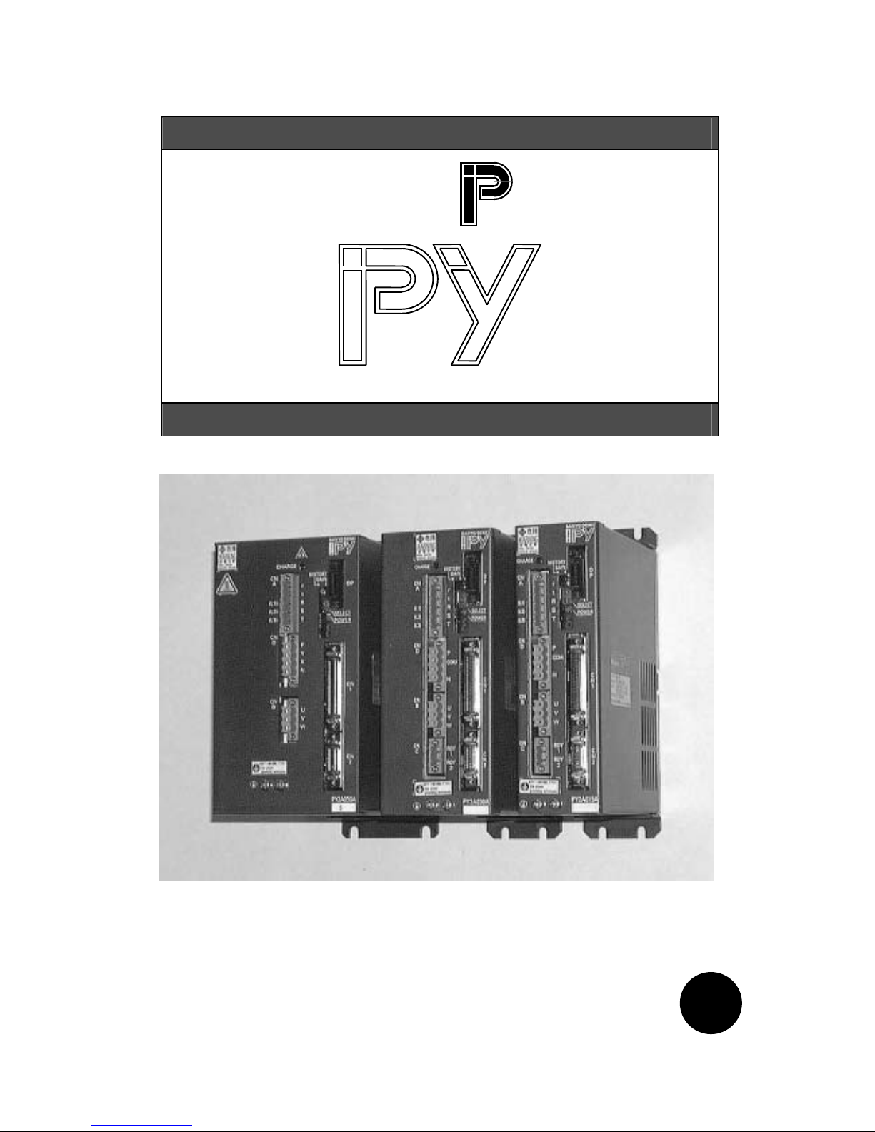
AC SERVO SYSTEM
BL Super Series
PY2
PY2 Servo Amplifier Instruction Manual
Released September 1999
Revision F April 2001
Revision J August 2003
SANYO DENKI CO.,LTD English
E
Page 2

This product does not qualify as strategic goods as specified by the Foreign Exchange
and Foreign Trade Control Law. Accordingly, applying for an export permit from the
Ministry of Economy, Trade & Industry is not required. For customs purposes, however,
an explanation may be required. So, please ask us for the material explaining that this
product is not applicable. In addition, when this product is incorporated into other
equipment, the applicable regulations must be complied with.
Page 3
i
PREFACE
The "PY" series Servo Amplifier is applicable to a wide range of applications from small to medium
capacity thanks to its multiple functions, high performance, downsizing and high cost performance.
The "PY2" was developed as an upgraded version of this "PY" series to satisfy customer needs for
further downsizing.
The "PY2" Servo Amplifier features the same performance as the "PY" series, on which it is based,
with only the size reduced. The small and high performance "PY2" Servo Amplifier is useful for a
large number of customers in applications requiring space saving.
This User's Manual explains the functions, wiring, installation, operation, maintenance and
specifications of the "PY2" Servo Amplifies and our Servomotors.
To completely utilize all functions of the "PY2" series, read this manual carefully before use to
ensure proper operation.
After reading this manual, keep it handy so that it can be referred to by anyone at anytime.
In this manual,
"AC Servomotor" is sometimes abbreviated to "Servomotor" or "Motor".
"AC Servo Amplifiers" to "Servo Amps." or "Amps.".
Also, "Wiring-saved incremental encoders" and "Request signal-unavailable
absolute encoders" are sometimes abbreviated to "Encoders" and "Wiring-saved
incremental encoders", "Request signal-unavailable absolute encoders" and
"Request-available absolute sensors" to "Sensors".
Page 4
i
International Standard Compliance
The “PY2” Servo Amplifier complies with the following International standards.
International standard Standard No.
TÜV EN50178
UL UL508C
CUL UL508C
Low Voltage Directive EN50178
EMC Directive EN55011
Working Environment
Since the working environment for the “PY2” Servo Amplifiers must be pollution level 2 or above (i.e. level 1
or 2) as specified in EN50178, be sure to use them in a pollution level 1 or 2 environment.
Power Supply
The “PY2” Servo Amplifiers must be used under the conditions specified in overvoltage category II, EN
50178. Use a reinforced insulation transformer conforming to the EN Standard for power supply input.
For the interface, use a DC power supply whose input and output sections have reinforced-insulation.
Page 5
i
CE Marking
At Sanyo Denki, we are executing tests on the “PY2” Servo Amplifier for compliance with the CE marking at
qualifying institutions. The CE mark is required to be attached all end products sold in EU countries.
Only products conforming to the safety standards are permitted to have them. Accordingly, customers are
requested to perform the final conformity test on their machines or systems incorporating our amplifiers.
The CE Marking Conformity Standards
We execute conformity tests for the following standards on the “PY2” Servo Amplifier at qualifying
institutions.
Classification of
directive
Classification Test Test standard
Low Voltage
Directive
- - EN50178
Terminal interference voltage EN55011
Emission
Electromagnetic radiation
interference
EN55011
Radiation field immunity
EN61000-4-3 / 1996
ENV50204 / 1995
Conductivity immunity EN61000-4-6 / 1996
Electrostatic immunity
EN61000-4-2
EN61000-4-2 : A1 / 1998
Electrostatic immunity
EN61000-4-2
EN61000-4-2 : A1 / 1998
EMC Directive
Immunity
Burst immunity EN61000-4-4 / 1995
File numbers
Low Voltage Directive, Declaration : File No. C0002827C
Low Voltage Directive, Certification : File No. B 01 05 21206 040 (Messrs. TÜV PRODUCT SERVICE)
EMC Directive, Declaration : File No. C0004056
EMC Directive, Certification : File No. E9 99 05 30982 005 (Messrs. TÜV PRODUCT SERVICE)
UL Marking
The “PY2” series products are qualified to have the UL (U.S. version) and cUL (Canada version) marks of
the Underwriters Laboratories attached.
File Numbers
File No.: E179775 Power Conversion Equipment (CCN: NMMS, NMMS7)
Fuse
The “PY2” Servo Amplifiers are not equipped with fuses. Customers are requested to prepare a
UL-approved fast-blown fuse and install it in the input section of the main circuit power supply.
Page 6

iv
CONTENTS
0. SAFETY PRECAUTIONS
0.1 Introduction ..................................................................................................................... 0-2
0.2 "Warning Label" Location on Product ............................................................................. 0-2
0.3 Meaning of Warning Indication ....................................................................................... 0-3
0.3.1 Details of Indications ........................................................................................... 0-3
0.3.2 Rank of Cautions on Safety................................................................................. 0-3
0.3.3 Symbolic Indication.............................................................................................. 0-4
0.4 Cautions on Safety .........................................................................................................0-5
1. BEFORE OPERATION
1.1 Precaution on Unpacking ................................................................................................. 1-2
1.2 Confirmation of the Product.............................................................................................. 1-2
1.3 Precautions on Operation................................................................................................. 1-2
1.4 How to Read Model Numbers .......................................................................................... 1-6
1.4.1 Model Number of Servomotor ............................................................................. 1-6
1.4.2 Model Number of Servo Amplifier ....................................................................... 1-7
1.5 "PY2" Servo Amplifier Standard Combination.................................................................. 1-8
1.6 Flowchart for Determining Servomotor
Model Number .................................................................................................................. 1-9
2. FUNCTION, CHARACTERISTICS AND CONFIGURATION
2.1 "PY2" Servo Amplifier Built-in Functions.......................................................................... 2-2
2.2 Characteristics of "PY2" Servo Amplifier.......................................................................... 2-6
2.3 Characteristics of Servomotor .......................................................................................... 2-11
3. SERVO SYSTEM CONFIGURATION
3.1 Block Diagram .................................................................................................................. 3-2
3.2 External Mounting and Wiring Diagram............................................................................ 3-2
3.3 Names of Servo Amplifier Parts ....................................................................................... 3-3
3.3.1 PY2A015/030 ...................................................................................................... 3-3
3.3.2 PY2E015/030 ...................................................................................................... 3-4
3.3.3 PY2A050 ............................................................................................................. 3-5
3.4 Optional Peripheral Equipment List.................................................................................. 3-6
4. WIRING
4.1 Applicable Wire Sizes.......................................................................................................4-2
4.2 Specifications of Sensor Cable ........................................................................................ 4-3
4.3 External Wiring Diagram................................................................................................... 4-4
4.3.1 External Wiring Diagram (200 VAC Input Type) ................................................. 4-4
4.3.2 External Wiring Diagram (100 VAC Input Type) ................................................. 4-6
Page 7

v
4.3.3 Sensor Connection Diagram (INC-E).................................................................. 4-8
4.3.4 Sensor Connection Diagram (ABS-E) ................................................................. 4-9
4.3.5 Sensor Connection Diagram (ABS-RII) .............................................................. 4-10
4.3.6 Sensor Connection Diagram (ABS-E.S1) ........................................................... 4-11
4.4 Connector Terminal Arrangement Input/Output Signal Diagram..................................... 4-12
4.4.1 CN1: Interface Connector.................................................................................... 4-12
4.4.2 CN2: Sensor Connector ...................................................................................... 4-13
4.5 Wiring Procedure.............................................................................................................. 4-15
4.6 Precautions on Wiring ...................................................................................................... 4-16
4.6.1 Recommended Surge Protector.......................................................................... 4-17
4.6.2 CN1 & CN2 Shielding Procedure ........................................................................ 4-18
4.6.3 Typical CN2 Compression Insert Application...................................................... 4-20
5. INSTALLATION
5.1 Servo Amplifier Installation............................................................................................... 5-2
5.1.1 Installation Place ................................................................................................. 5-2
5.1.2 Installation Procedure.......................................................................................... 5-3
5.2 Servomotor Installation.....................................................................................................5-4
5.2.1 Installation Place ................................................................................................. 5-4
5.2.2 Installation Procedure.......................................................................................... 5-4
5.3 Cable Installation .............................................................................................................. 5-9
6. OPERATION
6.1 Operation Sequence......................................................................................................... 6-2
6.1.1 Power ON Sequence........................................................................................... 6-2
6.1.2 Stop Sequence .................................................................................................... 6-3
6.1.3 Servo OFF Sequence.......................................................................................... 6-5
6.1.4 Alarm Reset Sequence ....................................................................................... 6-6
6.1.5 Overtravel Sequence........................................................................................... 6-7
6.2 Display.............................................................................................................................. 6-8
6.2.1 Status Display...................................................................................................... 6-8
6.2.2 Alarm Display ...................................................................................................... 6-8
6.3 Be Sure to Check the Functioning at First ....................................................................... 6-9
6.3.1 Minimum Wiring................................................................................................... 6-9
6.3.2 Jog Operation ...................................................................................................... 6-10
6.3.3 Resetting and Turning the Power Off.................................................................. 6-12
6.4. Encoder Clear Using Remote Operator
(When Absolute Encoder is Used) ................................................................................... 6-13
7. EXPLANATION OF PARAMETERS
7.1 Remote Operator (Optional)............................................................................................. 7-2
7.1.1 Outline of Remote Operator ................................................................................ 7-2
7.1.2 Function Table..................................................................................................... 7-3
7.1.3 Basic Operation Procedure ................................................................................. 7-4
Page 8

vi
7.1.4 Parameter Setting Mode
(Screen Mode 0 to 2 and 8)................................................................................. 7-5
7.1.5 Parameter Increment/Decrement Mode
(Screen Mode 3).................................................................................................. 7-8
7.1.6 Parameter Select Mode (Screen Mode 4)........................................................... 7-10
7.1.7 Monitor Mode (Screen Mode 5)........................................................................... 7-12
7.1.8 Alarm Trace Mode (Screen Mode 6)................................................................... 7-14
7.1.9 Test Mode (Screen Mode 7)................................................................................ 7-19
7.1.9.1 JOG Operation.................................................................................................. 7-18
7.1.9.2 Off Line Auto-tuning Function........................................................................... 7-20
7.1.9.3
7.2 Description of Parameters................................................................................................ 7-25
7.2.1 Block Diagram of Position, Velocity and
Torque Control Type Parameters........................................................................ 7-25
7.2.2 Parameter Summary Table ................................................................................. 7-26
7.2.3 Parameter List ..................................................................................................... 7-29
8. MAINTENANCE
8.1 Troubleshooting (Alarm)................................................................................................... 8-2
8.2 Troubleshooting (Non-Alarm) ........................................................................................... 8-20
8.3 Switching of Velocity Loop Proportional Gain Using Rotary Switch................................. 8-23
8.3.1 Overview.............................................................................................................. 8-23
8.3.2 Setting Procedure................................................................................................ 8-23
8.4 Maintenance ..................................................................................................................... 8-24
8.5 Overhaul Parts.................................................................................................................. 8-25
9. SPECIFICATIONS
9.1 Servo Amplifier ................................................................................................................. 9-3
9.1.1 Common Specifications....................................................................................... 9-3
9.1.2 Acceleration and Deceleration Time ................................................................... 9-5
9.1.3 Allowable Repetition Frequency.......................................................................... 9-6
9.1.4 Precautions on Load ........................................................................................... 9-9
9.1.5 CN1 Input/Output Interface Circuit Configuration................................................ 9-10
9.1.6 Position Signal Output ......................................................................................... 9-13
9.1.7 Monitor Output..................................................................................................... 9-17
9.1.8 Position Control Type Specifications................................................................... 9-20
9.1.9 Velocity/Torque Control Type Specifications ...................................................... 9-28
9.1.10 Switching of the Control Mode ............................................................................ 9-35
9.1.11 Internal Velocity Command ................................................................................. 9-36
9.1.12 Power Supply Capacity ....................................................................................... 9-37
9.1.13 Servo Amplifier/Servomotor Leakage Current .................................................... 9-39
9.1.14 Calorific Value ..................................................................................................... 9-40
9.1.15 Dynamic Brake .................................................................................................... 9-42
9.1.16 Regenerative Processing .................................................................................... 9-45
9.2 Servomotor ....................................................................................................................... 9-48
Page 9

vii
9.2.1 Common Specifications....................................................................................... 9-48
9.2.2 Revolution Direction Specifications ................................................................... 9-49
9.2.3 Motor Mechanical Specifications......................................................................... 9-50
9.2.4 Holding Brake Specifications............................................................................... 9-53
9.2.5 Motor Data Sheet ................................................................................................ 9-55
9.3 External Views.................................................................................................................. 9-125
9.3.1 Servo Amplifier .................................................................................................... 9-125
9.3.2 Servomotor .......................................................................................................... 9-126
9.3.3 Remote Operator (Option)................................................................................... 9-140
9.4 External Regenerative Resistor (Optional) ..................................................................... 9-141
9.4.1 How to Connect and Set External Regenerative Resistor (Optional) ................. 9-141
9.4.2 External Regenerative Resistor Combination Table ......................................... 9-144
9.4.3 External Regenerative Resistor List.................................................................... 9-147
9.4.4 Detailed Connecting Methods of External Regenerative Resistor...................... 9-148
9.4.5 External Regenerative Resistor Outline Drawings.............................................. 9-149
9.5 Full Close Function (Option)............................................................................................. 9-151
9.5.1 Rough Diagram of Full Close Function (Option).................................................. 9-151
9.5.2 Hardware of Full Close Function (Option)............................................................ 9-152
9.5.3 Parameter of Full Close Function (Option) .......................................................... 9-153
10. INTERNATIONAL STANDARDS
10.1 International Standard Conformity.................................................................................... 10-2
10.1.1 Outline................................................................................................................. 10-2
10.1.2 International Standard Conformity for PYR Servo System ................................. 10-2
10.2 Cautions for International Standard Conformity ............................................................... 10-3
10.2.1 Cautions Common to UL/TUV Conformity .......................................................... 10-3
10.3 UL/cUL/TUV Standard Conformity ................................................................................... 10-4
10.3.1 UL/cUL Conformity and File Numbers ................................................................ 10-4
10.3.2 TUV Conformity and File Numbers ..................................................................... 10-5
10.4 Conformity with EC Directives.......................................................................................... 10-5
10.4.1 Outline................................................................................................................. 10-5
10.4.2 Conformity with EC Directives ............................................................................ 10-5
10.4.3 CE Marking Conformity Standard....................................................................... 10-6
10.4.4 Cautions for EMC Directive Conformity.............................................................. 10-7
11. PY PC INTERFACE
11.1 Outline of Servo Function ................................................................................................. 11-2
11.2 Control Mode Switch ........................................................................................................ 11-3
11.3 Gain Switch ...................................................................................................................... 11-4
11.4 Real Time Automatic Tuning............................................................................................ 11-5
11.5 Additional Function of Velocity Loop Proportional Gain................................................... 11-9
11.6 P-PI Control Automatic Switch ......................................................................................... 11-9
11.7 Full Close Function........................................................................................................... 11-10
Page 10
0. SAFETY PRECAUTIONS
0-1
SAFETY PRECAUTIONS
0.1 Introduction ................................................................................ 0-2
0.2 "Warning Label" Location on Product ......................................... 0-2
0.3 Meaning of Warning Indication ................................................... 0-3
0.3.1 Details of Indications ......................................................... 0-3
0.3.2 Rank of Cautions on Safety............................................... 0-3
0.3.3 Symbolic Indication ........................................................... 0-4
0.4 Cautions on Safety ..................................................................... 0-5
This chapter summarizes the precautions to ensure safe operation of
the PY2 Servo Amplifier.
Be sure to read this chapter before operation.
Page 11

0. SAFETY PRECAUTIONS
0-2
0.1 Introduction
The “PY2” Servo Amplifier is designed to be used for general industrial equipment. So, note the following
precautions.
• To ensure proper operation, thoroughly read the Instruction Manual before installation, wiring and
operation.
• Do not modify the product.
• For installation or maintenance, consult our dealer or authorized agency.
• When using the product for the following purposes, special measures, such as system multiplication or
emergency power generator installation, should be taken regarding operation, maintenance and
management of the product. In this case, consult us.
① Use in medical equipment affecting people's lives.
② Use in equipment that may be lead to physical injury, for example, trains or elevators.
③ Use in a computer system that may be socially or publicly influential.
④ Use in other equipment related to physical safety or equipment that may affect the functions of
public facilities.
• For use in an environment subject to vibration, for example, on-vehicle use, consult us.
Be sure to read all parts of this manual before use (installation, operation, maintenance, inspection, etc.) to
properly use the equipment and only start using it after completely understanding all aspects, safety
information and precautions relating to the equipment.
Keep this manual handy after reading it.
0.2 "Warning Label" Location on Product
The warning label is on the front upper left of the Servo Amplifier.
Page 12
0. SAFETY PRECAUTIONS
0-3
0.3 Meaning of Warning Indication
This chapter explains how warnings are indicated.
Please understand the details of indications before reading 0.4 Cautions on Safety.
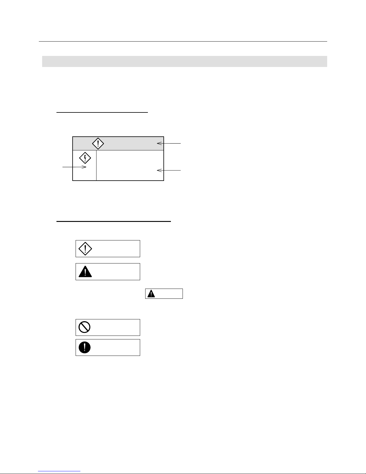
0.3.1 Details of Indications
Section 0.4 describes as follow s:
① : Rank of cautions on safety
② : Symbolic indication
③ : Meaning of each symbolic indication
0.3.2 Rank of Cautions on Safety
Cautions are divided into the following four ranks:
①
Incorrect operation may result in such a dangerous situation as
death or serious injury.
②
Incorrect operation may result in such a dangerous situation as
medium or slight injury or may result in only physical damage.
Note that some indications with may lead to serious results depending on situations.
Since any indications are important, be sure to observe them.
③ What should not be done are indicated.
④ What should be done by all means are indicated.
DANGER
1. The amplifier inside
①
②
③
DANGER
CAUTION
PROHIBITION
COMPULSION
CAUTION
Page 13
0. SAFETY PRECAUTIONS
0-4
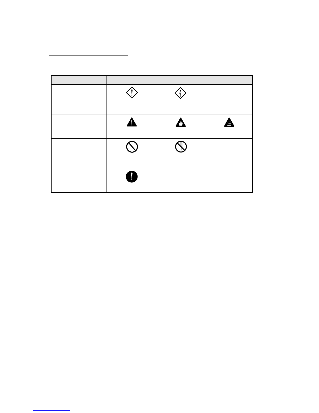
0.3.3 Symbolic Indication
Symbolic indications are divided into the following eight kinds:
Kinds of symbols Example of symbols
Symbolic indications of
danger
DANGER,
INJURY
ELECTRIC
SHOCK
Symbolic indications
calling attention
CAUTION
FIRE
BURN
Symbolic indications
prohibiting actions
PROHIBITION
PROHIBITION OF
DISASSEMBLING
Symbolic indication
urging actions
MANDATORY
Page 14
0. SAFETY PRECAUTIONS
0-5
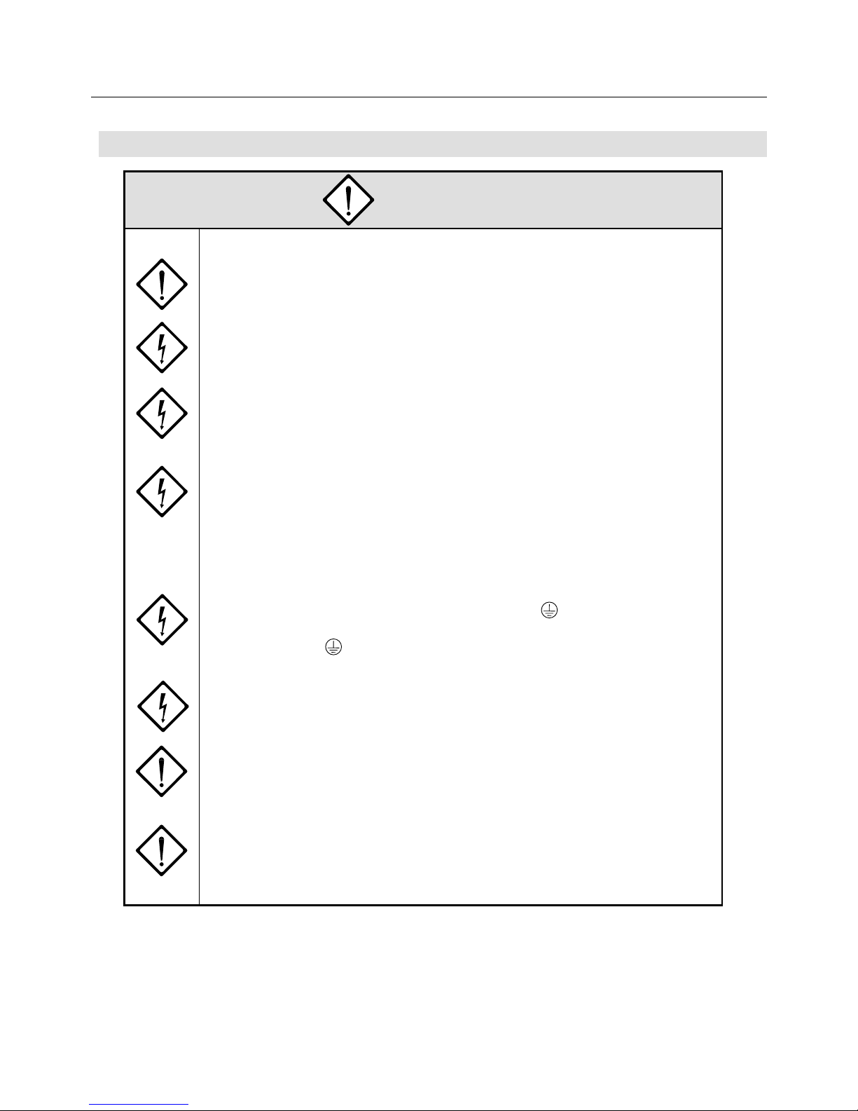
0.4 Cautions on Safety
DANGER
<General>
1. Don't operate the system in explosive environment, or you may be injured or fire
may occur.
2. Never touch any inside part of the amplifier, or you may be struck by electricity.
3. Don't arrange wires nor conduct maintenance work and inspection under a
hot-line condition.
Be sure to turn the power off more than 5 minutes in advance.
Otherwise, you may be struck by electricity.
4. Ask experts in respective fields for transportation, installation, wiring, operation,
maintenance and inspection.
Persons without expertise may receive electric shocks, be injured or fire may
occur.
<Wiring>
5. Be sure to ground the PE (protective earth) terminal of the amplifier.
The grounding terminal of the motor must be connected to the PE (protective
earth) terminal of the amplifier. Otherwise, an electric shock may occur.
6. Don't damage cable, stress them abnormally, place heavy items on them nor get
them caught between other parts or devices.
Otherwise, an electric shock may occur.
7. Be sure to connect the power cable in accordance with the connection diagram
or the User's Manual.
Otherwise, you may be struck by electricity, or fire may occur.
8. Since no fuse is built into the main power supply input terminals (R, S and T) of
the amplifier, be sure to insert a UL-approved circuit breaker or fast-blown fuse to
the amplifier power supply input wiring to protect it and its peripherals.
Page 15
0. SAFETY PRECAUTIONS
0-6
DANGER
<Operation>
9. During operation, never touch the motor rotator, or you may be injured.
10. While the power is supplied, never approach nor touch terminals, or you may be
struck by electricity.
11. While the power is supplied, never remove any terminal cover, or you may be
struck by electricity.
Page 16
0. SAFETY PRECAUTIONS
0-7
CAUTION
<General>
1. Before installation, operation, maintenance and inspection, be sure to read the
User's Manual and follow instructions detailed in the manual.
Otherwise, you may be struck by electricity or be injured, or fire may occur.
2. Don't use the amplifier and the motor in any situations where the specifications
are not fully satisfied.
Otherwise, you may be struck by electricity or injured, or they may be damaged.
3. Don't use the amplifier and the motor if they are damaged.
Otherwise, you may be injured or fire may occur.
4. Use the amplifier and the motor only in the combination specified, or fire or a
trouble may occur.
5. Note that the amplifier, the motor and their peripheral equipment are heated to
high temperatures.
Don't touch them, or you may be burnt.
<Unpacking>
6. Check which side is up before unpacking, or you may be injured.
7. Check if what you have received are as per your order.
Installation of an incorrect product may result in injury to you or breakage of the
product.
8. Don't apply static electricity to the motor sensor terminal, or the motor may get
out of order.
Page 17
0. SAFETY PRECAUTIONS
0-8
CAUTION
<Wiring>
9. Don't measure insulation resistance and dielectric strength, or these units may
be damaged.
When you have to measure them, please contact us.
10. Arrange cables in accordance with the Technical Standard for Electric Facilities
and the Extension Rules.
Otherwise, cables may be burnt and fire may occur.
11. Arrange cables correctly and securely, or the motor may run away and you may
be injured.
12. Don't apply static electricity or high voltage to the motor sensor terminal, or the
motor may get out of order.
<Installation>
13. Don't climb up these units nor place heavy substance on them, or you may be
injured.
14. Don't stop the air inlets and outlets nor put foreign matters in them, or fire may
occur.
15. Be sure to observe the direction of installation, or a trouble will occur.
16. Decide the distances between the amplifier, the inside surface of the control
panel and other equipment in accordance with the User's Manual.
Otherwise, troubles may occur.
17. Don't shock these units badly, or they may be get out of order.
18. During installation, take an extreme care not to drop nor overturn these units, or
you may face serious dangers.
When raising the motor, use the lifting bolt if it is fitted.
19. Never install these units where they are exposed to splash of water, in corrosive
or inflammable gas atmosphere or near combustibles.
Otherwise, fire may occur or they may get out of order.
20. Install them to any of nonflammables like metal, or fire may occur.
Page 18
0. SAFETY PRECAUTIONS
0-9
CAUTION
<Operation>
21. This motor is not equipped with any protective device.
So, protect it with an overcurrent device, an earth leakage breaker, a thermal
cutout or an emergency stop device.
Otherwise, you may be injured or fire may occur.
22. During the power is supplied or for a while after the power is turned off, don't
touch the amplifier radiator, the regenerative resistor and the motor because they
are or have been heated to high temperatures.
Otherwise, you may be burnt.
23. When any trouble has occurred, stop operating the system immediately, or you
may be struck by electricity or injured, or fire may occur.
24. An extreme adjustment change will make the system operate unstably. Never
make such a change, or you may be injured.
25. To check operation of the system in a trial run, fix the motor and separate it from
the mechanical system.
Otherwise, you may be injured.
After the trial run, mount it on the system.
26. The holding brake is not a stopping device to operate the system safely.
So, install a stopping device to the system for the purpose, or you may be
injured.
27. When an alarm occurs, remove the cause and check that the system is in safety.
Then, reset the alarm and resume the operation.
Otherwise, you may be injured.
28. When the power is restored after momentary interruption, don't approach the
system because it may suddenly start again.
(Design the system so that the operator can remain safe even if it may start
again.)
Otherwise, you may be injured.
29. Check that the power supply specification is normal.
Otherwise, troubles may occur.
Page 19
0. SAFETY PRECAUTIONS
0-10
CAUTION
<Maintenance>
30. Since the amplifier frame is heated to high temperature, beware of it at the time
of maintenance and inspection, or you may be burnt.
31. The electrolytic capacitor inside the amplifier is recommended to be replaced
with a new one every five years for preventive maintenance providing that the
yearly ambient temperature is 40°C.
The expected life of the cooling fan motor is 10 years at the yearly ambient
temperature of 40°C. Regular replacement is recommended.
32. In case of repair, please contact us.
If these units are disassembled by yourself, they may malfunction.
<Transportation>
33. During transportation, take an extreme care not to drop nor overturn these units,
or you may face serious dangers.
34. During transportation, don't catch cables and the motor shaft, or these unit may
get out of order or you may be injured.
<Disposal>
35. Dispose of the amplifier and the motor as general industrial wastes.
Page 20
0. SAFETY PRECAUTIONS
0-11
PROHIBITION
<Storage>
1. Don't store these units where they are exposed to water, rain drops, hazardous
gas or liquid.
Otherwise, they will get out of order.
<Operation>
2. The built-in brake of the motor is for holding and should not be used for braking
in general.
If used for braking, the brake will be broken.
<Maintenance>
3. Don't overhaul the system, or fire will occur and you will be struck by electricity.
<General>
4. Do not remove the nameplate.
Page 21
0. SAFETY PRECAUTIONS
0-12
MANDATORY
<Storage>
1. Store these units where they are not exposed to direct sunlight and in the
specified ranges of temperature and humidity {–20°C to +65°C, below 90%RH
(without dew condensation)}.
2. When the amplifier was stored for a long period (over 3 years as a guide), please
contact us for how to treat it.
When it is stored for a long time, the electrolytic capacitor capacity will decrease
and any trouble may occur.
<Operation>
3. Install an emergency stop circuit outside the system so that operation can be
stopped immediately and that the power supply can be shut off.
4. When the alarm generates, assemble the safety circuit outside of the amplifier.
Running away, injury, burning, fire, and secondary damage may be caused.
5. Operate the system within the specified ranges of the temperature and humidity
(see below).
Amplifier: Temperature = 0 to 55°C, Humidity = 90% RH or lower (no dew
condensation)
Motor: Temperature = 0 to 40°C, Humidity = 90% RH or lower (no dew
condensation)
<Transportation>
6. Overloaded products will collapse.
So, load them in accordance with the indication on the outer cases.
7. Use the lifting bolts on motors for carrying motors only and don't use them for
carrying machines.
Page 22

1. BEFORE OPERATION
1-1
BEFORE OPERATION
1.1 Precaution on Unpacking ............................................................. 1-2
1.2 Confirmation of the Product .........................................................1-2
1.3 Precautions on Operation ............................................................ 1-2
1.4 How to Read Model Numbers...................................................... 1-6
1.4.1 Model Number of Servomotor ........................................... 1-6
1.4.2 Model Number of Servo Amplifier ..................................... 1-7
1.5 PY2 Servo Amplifier Standard Combination ................................ 1-8
1.6 Flowchart for Determining Servomotor
Model Number ............................................................................. 1-9
Page 23
1. BEFORE OPERATION
1-2
Please operate this system taking the contents of the following description into consideration.
A misoperation will lead to an unexpected accident or damage.
1.1 Precaution on Unpacking
When unpacking this product after purchasing, care is needed to the following.
• When unpacking the Servo Amplifier, don't touch its printed circuit boards in any case.
1.2 Confirmation of the Product
Check the following after receiving the product. Contact us if any abnormality is detected.
• Check if the model numbers of the Servomotor and the Servo Amplifier match those of the ordered ones
(the numbers are described after "MODEL" on the main nameplate).
• Check the appearance of the Servomotor and the Servo Amplifier to confirm that they are free from any
abnormality such as breakage or lack of parts.
• Check that all screws on the Servomotor and the Servo Amplifier are tightened properly.
1.3 Precautions on Operation
Take care the following during operation.
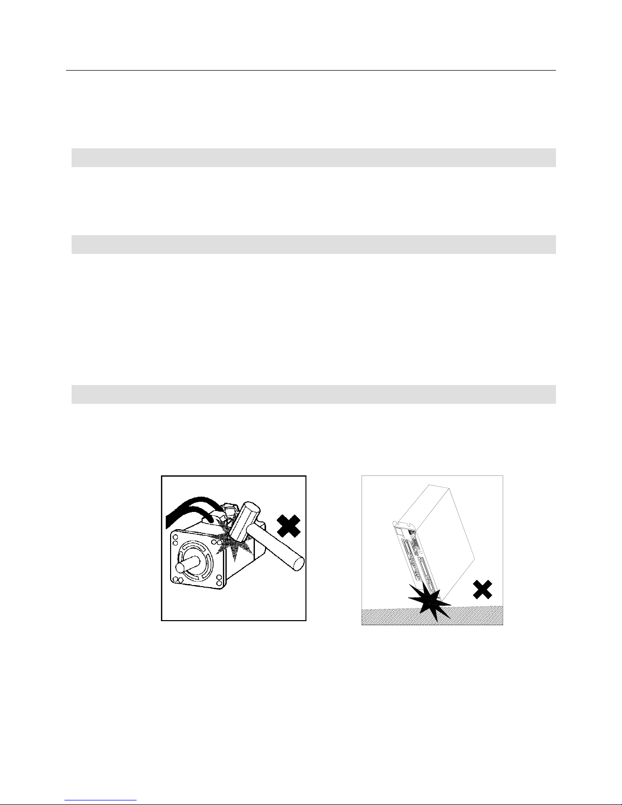
• At installation, don't give shocks to the Servomotor and the Servo Amplifier, or they may break.
In particular, handle the Servomotor carefully since it is provided with a sensor.
Page 24
1. BEFORE OPERATION
1-3
• Be sure to use a power supply within the specified range.
200 VAC input type: PY2A…, PY2B…
200 VAC to 230 VAC (+10%, −15%) 50/60 Hz
100 VAC input type: PY2E…, PY2F…
100 VAC to 115 VAC (+10%, −15%) 50/60 Hz
If a power supply other than the above is used, an accident may result.
• When a surge voltage is produced in the power supply, connect a surge absorber or others between the
powers to absorb the voltage before operation.
Otherwise malfunction or breakage may result.
• Turn the power on and off during maintenance and inspection after safety (such as the situation of the
load) is completely checked. If the power is turned on or off during the load is applied, an accident or
breakage may result.
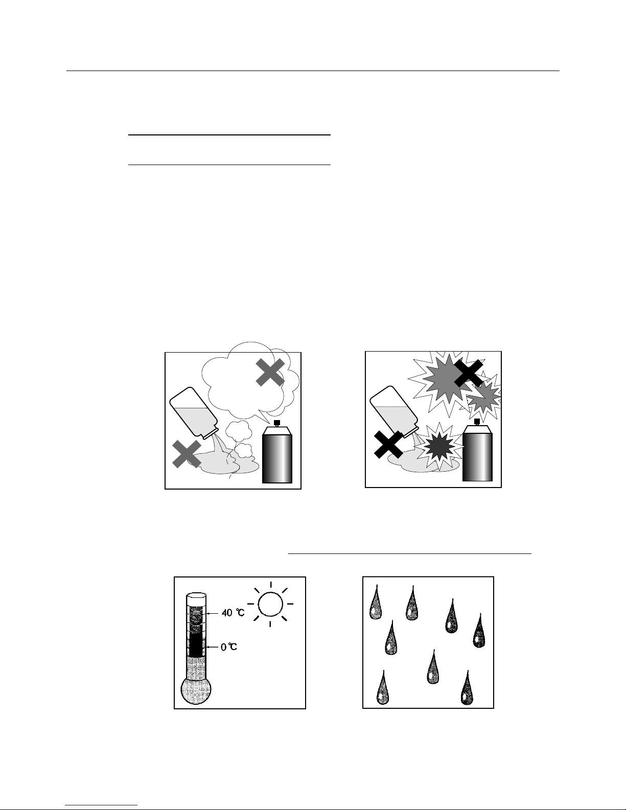
• Never use this product where corrosive (acid, alkali, etc.), flammable or explosive liquid or gas exists to
prevent it from deforming or breaking.
• Never use this product where flammable or explosive liquid or gas exists since the liquid or the gas may
be ignited, causing great danger.
Corrosives
Gas
Acid/Alkali
Flammables
Explosives
• Use this product within the ambient temperature range from 0°C to 40°C (0°C to 55°C for the Servo
Amplifier) and below the relative humidity limit of 90%.
• The Servomotor and the Servo Amplifier should be kept away from water, cutting fluid or rainwater
.
Otherwise electric leakage or and electric shock may result.
Page 25
1. BEFORE OPERATION
1-4
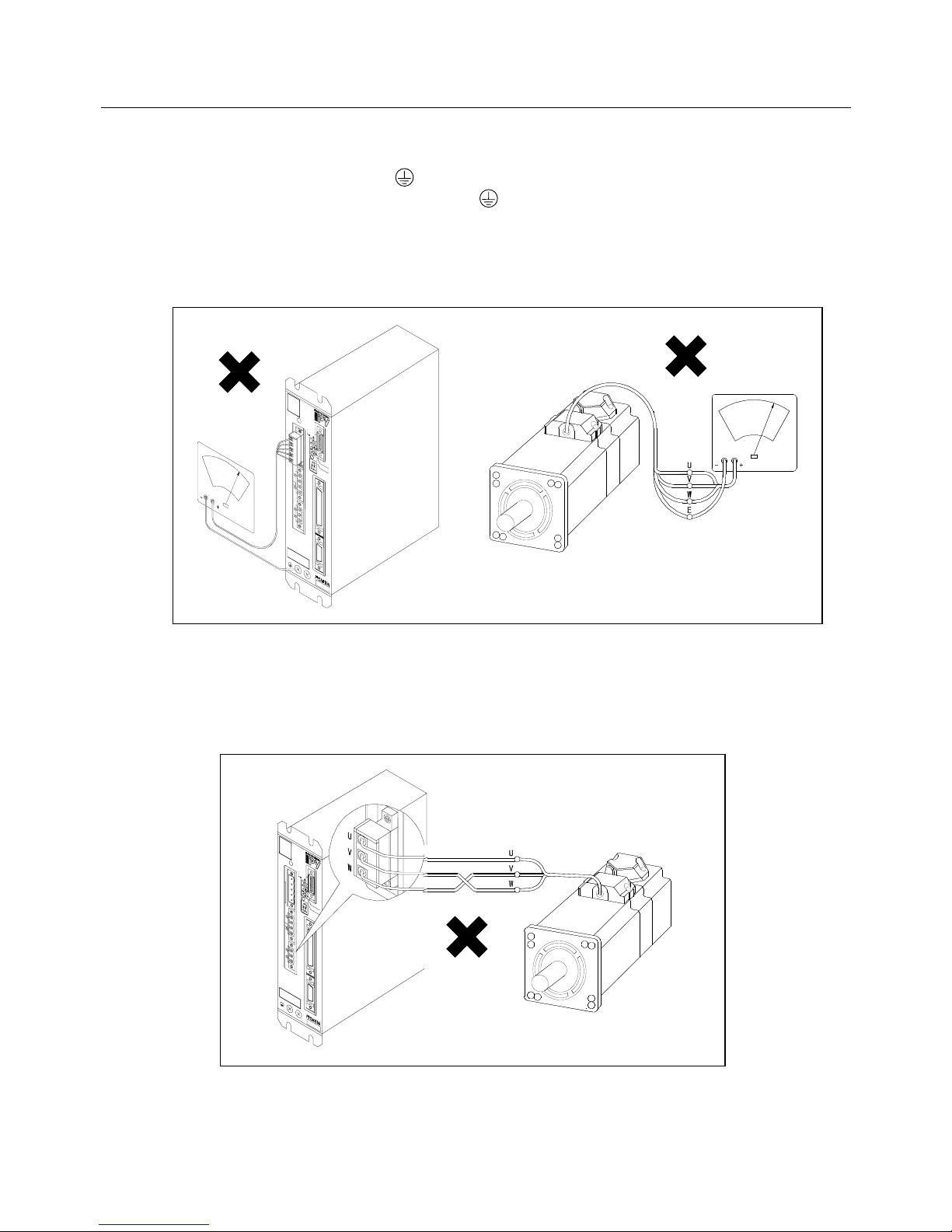
• For operating safety, check that the Servo Amplifier is grounded by at least a class 3 (less than 100Ω) of
the PE (protective earth) terminal . In addition, the grounding terminal of the Servomotor must be
connected to the PE (protective earth) terminal .
• Never perform a withstand voltage or a megger test of the Servomotor or the Servo Amplifier.
In this product, 0V and the main body is earthed by the capacitor.
If such test is necessary, consult with us.
• Perform correct wiring by referring to the chapter "4. Wiring".
Wrong wiring may cause Servomotor's or amplifier's breakage.
• Since the "P" series Servomotor is not an induction motor, the direction of revolution cannot be changed
by swapping the phases.
To change the direction, use the remote operator.
• For safety operation, be sure to install a surge absorber on the relay, electromagnetic contactor,
induction motor and brake solenoid coils.
Page 26
1. BEFORE OPERATION
1-5
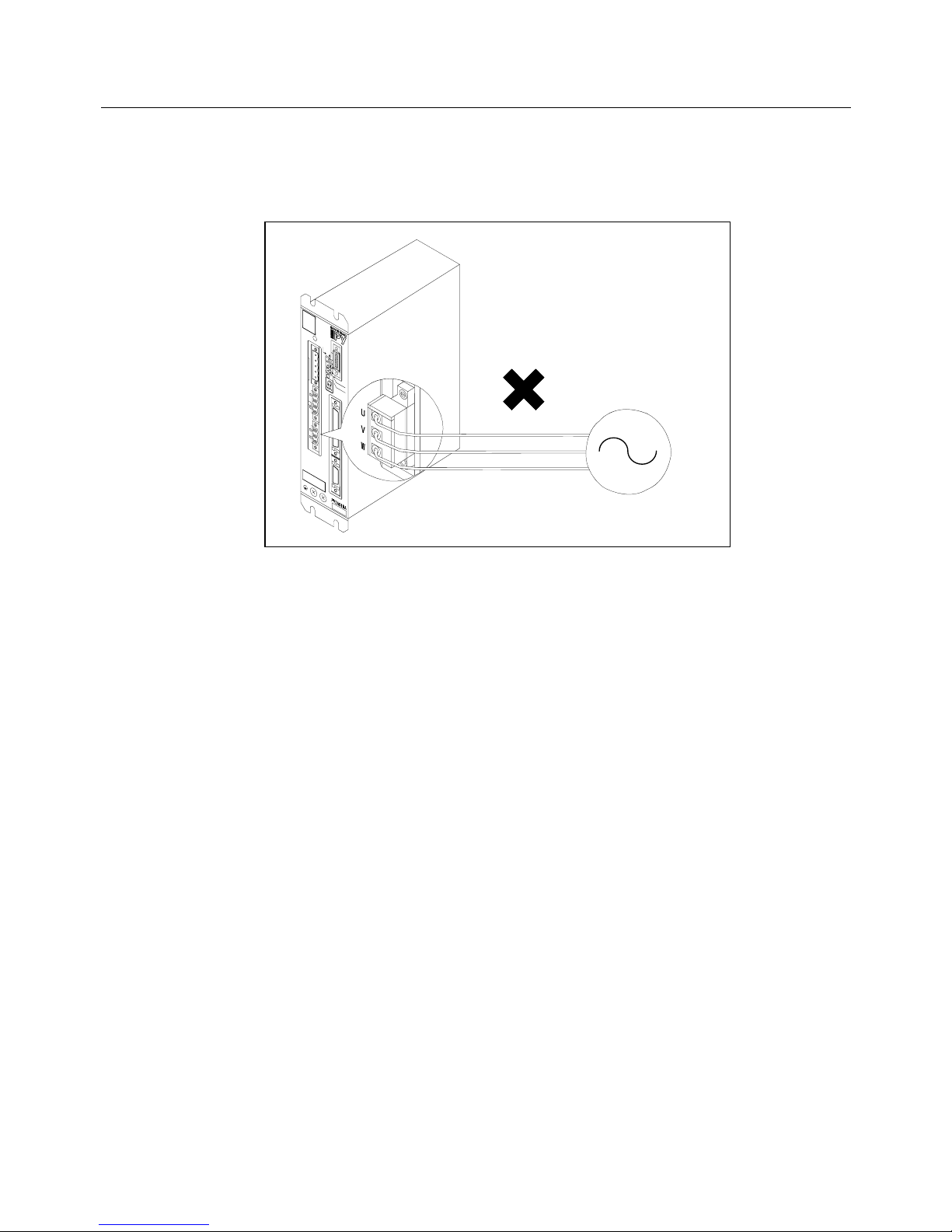
• Connect a power supply within the specified range to the Servo Amplifier’s R, S, T terminals respectively.
When a power supply out of the specified range is used, install a transformer.
If a commercial power supply is applied to the U, V or W terminal, the amplifier will break.
Commercial
power supply
Page 27
1. BEFORE OPERATION
1-6
1.4 How to Read Model Numbers
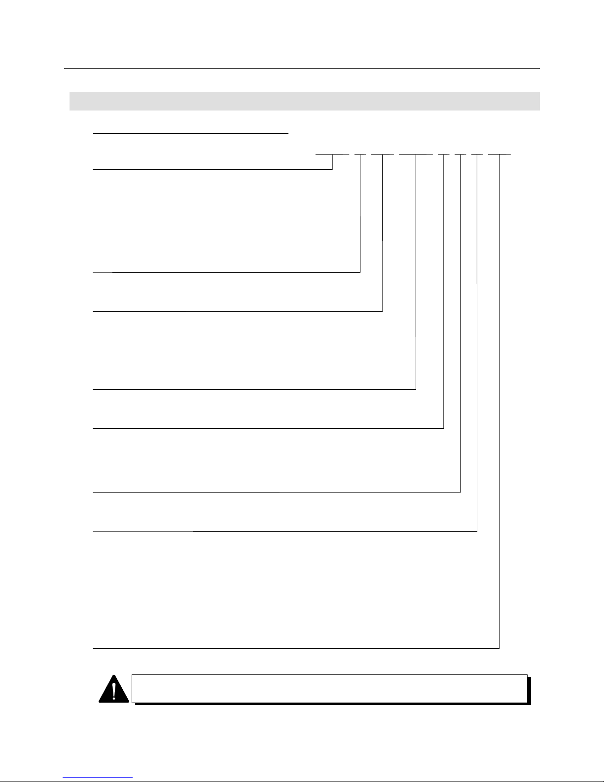
1.4.1 Model Number of Servomotor
1. BL series
P10...P1 series
P20...P2 series
P30...P3 series
P50...P5 series
P60...P6 series
P80...P8 series
2. Indicates the BL motor
3. Indicates flange square size
03…35 mm 04…40 or 42 mm 05…54 mm
06…60 mm 07…76 mm 08…80 or 86 mm
13…130 mm 15…150 mm 18…180 mm
22…220 mm
4. Indicates rated output
○○○ = ○○○ × 10 w
5. Maximum revolution speed
S…1000 min
−
1
M…1500 min
−
1
B…2000 min
−
1
R…2500 min
−
1
H…3000 min
−
1
D…4500 min
−
1
P…4500 min
−
1
6. Equipping of holding brake
X…Not equipped. B…Equipped. (90V) C…Equipped. (24V)
7. Type of detector
S… Wiring-saved incremental encoder
J… Absolute encoder with the motor flange square of 60 mm or less;
Request signal-unavailable type.
A… Absolute encoder with the motor flange square of 76 mm or more;
Request signal-unavailable type.
N... ABS-RII; Super-capacitor-unavailable, request signal-available type.
V... ABS-RII; Super-capacitor-built-in, request signal-available type.
8. Specification identification
00… Standard motor
B
○○○ ○○○ △ □ ◇○○ ▽▽
The design revision order is indicated by an alphabet at the end of Lot No. on the
nameplate.
Page 28
1. BEFORE OPERATION
1-7
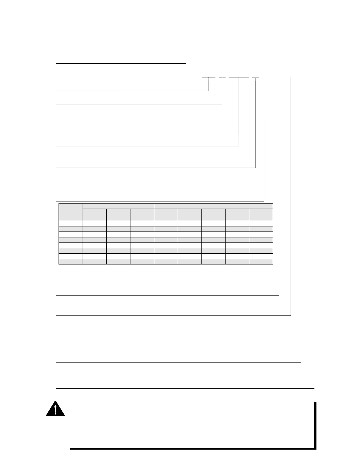
1.4.2 Model Number of Servo Amplifier
1. Indicates a PY2 servo amplifier
2. Type of power unit
A… For 200 VAC input, with dynamic brake
B… For 200 VAC input, without dynamic brake
E… For 100 VAC input, with dynamic brake
F… For 100 VAC input, without dynamic brake
3. Amplifier capacity
015… 15A 030… 30A 050...50A
4. Hardware type of control unit
A... Wiring-saved incremental encoder (INC-E) or request
signal-unavailable absolute encoder (ABS-E)
H... Request signal-available absolute sensor (ABS-RII)
P… Wiring-saved absolute sensor (ABS-E.S1)
5. Optional specifications of power supply input and power sections
6. Applicable motor
(For details, refer to the standard combination table on the next page. )
Example M1…P50B03003D□□□□ PA…P60B13050H□□□□
7. Type of applicable sensor
1... Wiring-saved incremental encoder (2000P/R)
2... Wiring-saved incremental encoder (6000P/R)
3... Request signal-unavailable absolute encoder (ABS-E, 2048P/R)
6... Request signal-available absolute encoder (ABS-RII, 8192P/R)
W…Wiring-saved absolute sensor (ABS-E.S1, 32768 dividing)
8. Interface specification
S…Speed control type. T…Torque control type. P…Position control type.
X…S-T switch type Y…P-T switch type U…P-S switch type V…Internal Speed control type
9. Discrete specification
00… Standard product
00
▽△
XX 0
PY2
○○○□
A
• The design revision order is indicated by an alphabet at the end of Lot No. on the
nameplate.
• In some Servo Amplifiers, the items 6 to 9 above are not specified. Servo Amplifiers
having the following model numbers can be used after specifying the parameters such as
motor, sensor and interface.
PY2A015A2 PY2A030A2 PY2A050A6 PY2E015A3 PY2E030A3
Model code Contents of specifications Support by power section type and amplifier capacity *3
Built-in
regenerative
resistor *1
RDY output
*2
Main circuit
power supply
type
PY2A015 PY2A030 PY2A050 PY2E015 PY2E030
0 × ○ 3-phase ○ ○ × × ×
1 × ○ Single phase ○ ○ × ○ ○
2 × × 3-phase ○ ○ × × ×
3 × × Single phase ○ ○ × ○ ○
4 ○ ○ 3-phase △ *4 ○ ○ × ×
5 ○ ○ Single phase △ *4 ○ ○ △*4 ○
6 ○ × 3-phase △ *4 ○ ○ × ×
7 ○ × Single phase △ *4 ○ ○ △*4 ○
*1: Built-in regenerative resistor: ○= with built-in regenerative resistor, ×= without built-in regenerative resistor
*2: RDY output: ○= with RDY output, ×= without RDY output
*3: Support by power section type and amplifier capacity ○= supportive, ×= not supportive
*4: For 15A regenerative resistor built-in type, configuration (dimension) of Amp. partially differs from standard.
Page 29
1. BEFORE OPERATION
1-8
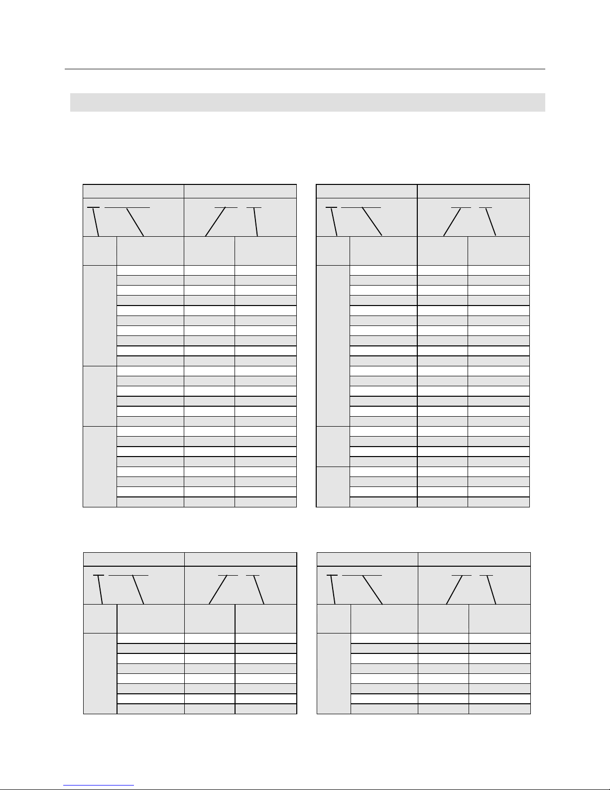
1.5 "PY2" Servo Amplifier Standard Combination
Check the model numbers of the motor and the amplifier on the combination table below.
If the combination is different, the system will not function properly.
Table1-1 "PY2" Servo Amplifier Standard Combination Table (200 VAC input type)
Table1-2 "PY2" Servo Amplifier Standard Combination Table (100 VAC input type)
Servomotor Servo Amplifier
P☆B○○○○○○□◇▽▽
PY2A○○○A2XX△▽00
Series
Flange square
Rated output
Maximum speed
Amplifier
capacity
Motor type
03003D 015 M1
04006D 015 M2
04010D 015 M3
05005D 015 M4
05010D 015 M5
05020D 015 M6
07020D 015 M8
07030D 015 M9
07040D 030 MA
08040D 030 MB
08050D 030 MC
08075D 050 MD
08100D 050 ME
08075H 030 MF
08100H 030 MG
P50
13050H 030 PA
13100H 050 P1
13150H 050 P2
P60
15075H 030 R2
18120H 050 R3
P80
Servomotor Servo Amplifier
P☆B○○○○○○□◇▽▽
PY2A○○○A2XX△▽00
Series
Flange square
Rated output
Maximum speed
Amplifier
capacity
Motor type
10030H 030 11
10075H 030 12
13050H 030 13
13100H 050 14
13150H 050 15
13050B 030 1A
13100B 030 1B
13150B 050 1C
18200B 050 1D
P10
10100D 050 21
10150D 050 22
10100H 030 28
10150H 050 29
10200H 050 2A
P20
04003D 015 N1
04005D 015 N2
04010D 015 N3
06020D 015 N4
06040D 030 N5
08075D 030 N6
P30
Servomotor Servo Amplifier
P☆B○○○○○○□◇▽▽
PY2E○○○A3XX△▽00
Series
Flange square
Rated output
Maximum speed
Amplifier
capacity
Motor type
03003P 015 MH
04006P 015 MJ
04010P 015 MK
05005P 015 ML
05010P 015 MM
05020P 030 MN
07020P 030 MR
P50
07030P 030 MS
Servomotor Servo Amplifier
P☆B○○○○○○□◇▽▽
PY2E○○○A3XX△▽00
Series
Flange square
Rated output
Maximum speed
Amplifier
capacity
Motor type
04003P 015 NA
04005P 015 NB
04010P 015 NC
06020P 030 ND
P30
Page 30
1. BEFORE OPERATION
1-9
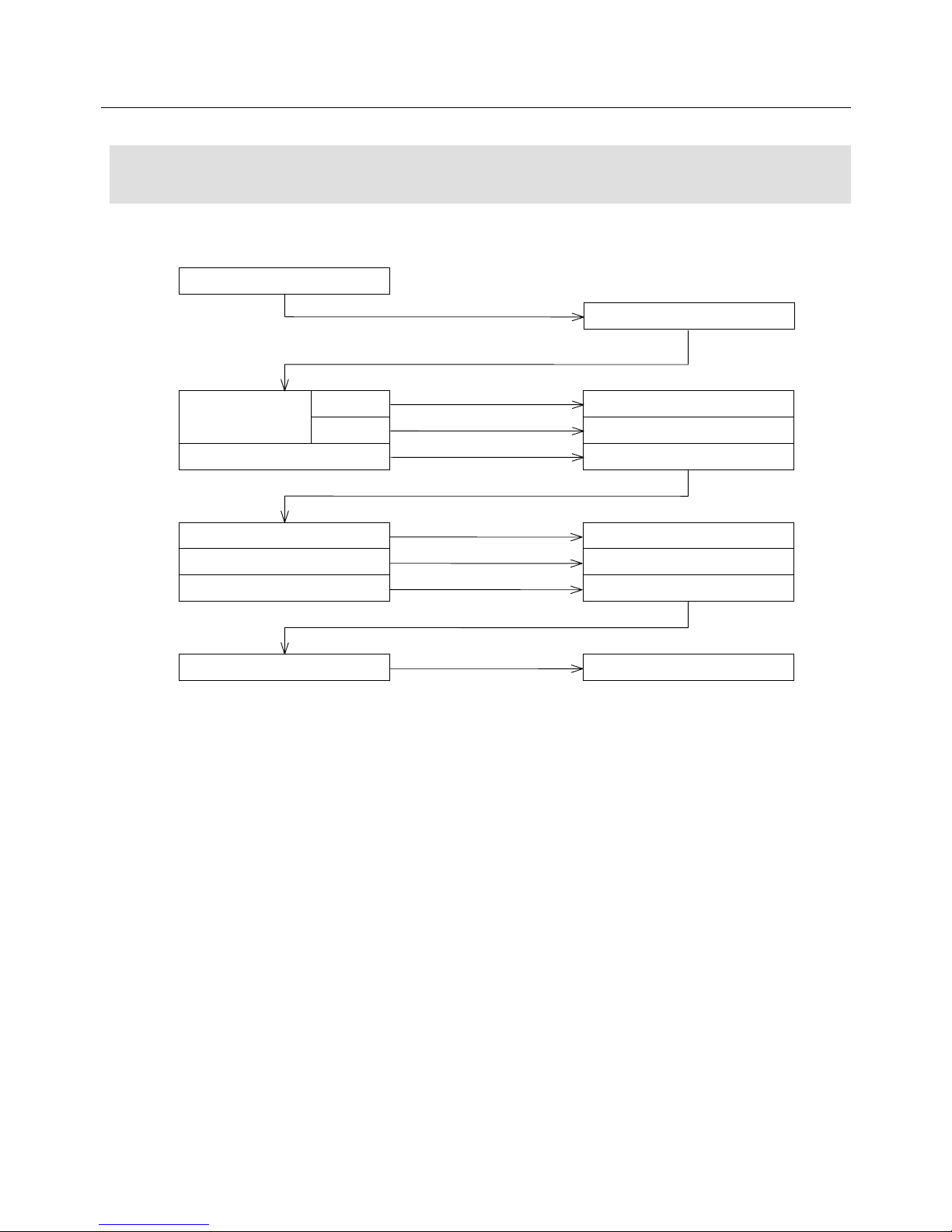
1.6 Flowchart for Determining Servomotor
Model Number
Refer to the following flowchart to determine the Servomotor model number.
Select Servomotor capacity.
With brake
90 V
24 V
Without brake
Determine capacity and
maximum speed.
Add B to the end.
Add C to the end.
Add X to the end.
P50B08100D
P50B08100DB
P50B08100DC
P50B08100DX
P50B08100DXS
P50B08100DXA
P50B08100DXS00
P50B08100DXN
Incre. 2000P/R
Standard specifications
Absol. 2048 divisions
ABS-RII 8192 divisions
Ex.
Ex. Sensor type
Add S to the end.
Add 00 to the end.
Consult with us for special
requirements.
Add A to the end.
Add N to the end.
Page 31

2. FUNCTION, CHARACTERISTICS AND CONFIGURATION
2-1
FUNCTION, CHARACTERISTICS
AND CONFIGURATION
2.1 "PY2" Servo Amplifier Built-in Functions...................................... 2-2
2.2 Characteristics of "PY2" Servo Amplifier...................................... 2-6
2.3 Characteristics of Servomotor......................................................2-11
Page 32

2. FUNCTION, CHARACTERISTICS AND CONFIGURATION
2-2
2.1 "PY2" Servo Amplifier Built-in Functions
This section describes the main built-in functions of the Servo Amplifier and additional functions specially for
the PY2 series.
The functions marked require the remote operator (see Chapter 7).
● Position, speed and torque control
The above three types are controlled as a package and can be selected using the remote operator.
The control type can be changed during operation (velocity ↔ torque, position ↔ torque, position ↔
velocity).
● Regenerative processing function
A regenerative processing circuit is built into the system, which enables regenerative processing simply
by externally connecting a resistor to the amplifier.
Since no regenerative resistor is built in except for 50 A type amplifier, one is required to be externally
connected to the amplifier when regenerative processing is required.
● Dynamic brake function
When the main circuit power supply is cut off, the dynamic brake is actuated.
However, this brake is operated regardless of the main circuit power supply when an alarm occurs.
● Holding brake excitation timing output
The power supply to the holding brake is controlled with the timing of this output signal, thereby
preventing a self-weight fall of the gravitational shaft at an emergency stop.
Keep this output open when the system is not operated.
● Vibration restraining function
If a vibration occurs when this function is incorporated in the system, the parameters "BEF" and "LPF"
are set by the remote operator according to the vibration frequency, restraining the vibration. When
offline, executing “auto notch filter tuning (Tune IBEF) at test mode can automatically set notch filter
frequency (IBF1). For more adequate setting, measure the oscillation frequency with an oscilloscope
on the current command monitor.
● Separation of control power and main circuit power
The control power and the main circuit power are separated.
When an alarm or an emergency stop occurs, the main circuit power alone can be cut off for safety, and
the control power can remain activated.
This enables the continuation of alarm output, making analysis and maintenance easy.
OP
OP
OP
Page 33
2. FUNCTION, CHARACTERISTICS AND CONFIGURATION
2-3
● Servo tuning support function
When the remote operator sets a mode, the load inertia is automatically estimated and a proper
parameter is set. There are two different kind of tuning methods: one is “Offline auto tuning” executed
at test mode when offline, and the other is “Online auto tuning” estimating appropriate gain and
changing the gain at real time during operation.
● Electric gear function
For a position control type, the feed can be changed without changing the mechanical gear by using this
electronic gear.
This gear is set by the remote operator.
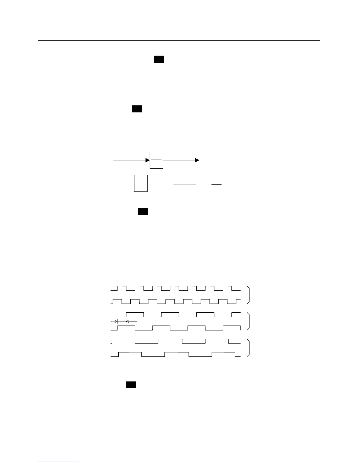
● Dividing output function
Encoder signal pulses can be output by being divided into N/8192 (N=1 to 8191), 1/N (N=1 to 64) or 2/N
(N=3 to 64) based on the setting by the remote operator.
Although the phase relation does not change, the 2/5 division is not the 90° phase difference.
To set the encoder signal dividing ratio, refer to the explanation on the parameters.
The dividing ratio must be a value with which the encoder pulse number can be divided.
For a 2000 pulses/rev encoder, for example, 1/3, 1/6 or 1/7 cannot be used since they are aliquant.
Some typical divided encoder output waveforms are described below.
● Alarm trace function
The past 7 alarm history data can be stored and reviewed from the remote operator or the front panel
SELECT, enabling easy troubleshooting.
OP
OP
OP
OP
Position command
f2
N
D
Input command pulse
When N = 1 to 32767 and
D = 1 to 32767
f2 = f1 ×
≦≦ 32767
f1
N
D
1
32767
N
D
90°
A-phase
Dividing ratio 1/1
B-phase
Dividing ratio 1/2
Dividing ratio 2/5
Typical encoder signal output waveforms (forward revolution)
A-phase
B-phase
A-phase
B-phase
Page 34
2. FUNCTION, CHARACTERISTICS AND CONFIGURATION
2-4
● Power supply type selection function (200 VAC input type)
Either a 3-phase, 200 VAC type or the single phase, 200 VAC type main power supply can be selected.
After selecting either one, simply turn the control power supply on again, no other parameter settings
are necessary. (Since some types of motors have different 3- or single-phase properties, refer to the
combination specifications in Section 9.)
● Applicable to wiring-saved incremental & absolute encoders
The same amplifier is applicable to an incremental encoder (INC-E) and an absolute encoder (ABS-E)
simply by changing the appropriate parameters using the remote operator.
Different motors, however, are required for the INC-E and the ABS-E, respectively.
● Applicable to absolute sensor (ABS-R II)
Applicable to an absolute sensor (ABS-R II).
● Applicable to Wiring-saved absolute sensor (ABS-E.S1)
Applicable to a wiring-saved absolute sensor (ABS-E.S1). Absolute sensor can be wiring-saved. In
use to application not requiring holding multi-rotational part, wiring number can be less then that for
wiring-saved incremental encoder (INC-E). In case of not requiring holding multi-rotational part, battery
connection is not necessary (Need parameter setting to select functions).
OP
OP
OP
Applicable Servo Amplifiers to absolute sensor (ABS-R II) and wiring-saved absolute sensor
(ABS-E.S1) have different internal circuits from incremental (INC-E) and absolute (ABS-E)
encoder-type amplifiers. Use product applicable to an absolute sensor.
OP
Page 35
2. FUNCTION, CHARACTERISTICS AND CONFIGURATION
2-5
Additional function specially for the PY and PY2 series (compared to PZ amplifiers)
In addition to the various control functions provided in the "PZ" series, the following functions have been
added to the "PY" and "PY2" series
1. Control mode switching function
This function is for switching the control mode without power shutdown.
2. Internal velocity command function
The amplifier has three types of velocity commands, and this function is for switching the velocity
command depending on the situation.
3. Function to correspond with the external encoder for full-close control
By providing an external incremental encoder process circuit in the amplifier, full-close control is
enabled. (For full-close correspondence, consult us, as additional parts are required.)
4. Gain switching using a rotary switch
By using a rotary switch, gain setting is enabled without connecting to a remote operator.
5. Gain switching function
Two types of gain settings can be selected in the amplifier. Gain switching is enabled depending on
the situation.
6. Upgrading of the personal computer interface functions
Following upgrading of the personal computer interface functions, graphic indication of the monitor data
and execution of various test modes have been enabled as well as parameter setting and editing using
a PC.
(See the instruction manual for the personal computer interface provided separately.)
7. Input command auto offset function
The analog input command auto offset function is added, which facilitates offset adjustment in the
velocity or torque control mode.
OP
OP
OP
OP
OP
OP
OP
Be sure to use the PY personal computer interface version 1.30 or later when combining the
100 VAC power input type (PY2E), single-phase power supply specification PY2 Servo
Amplifier with a personal computer interface.
(The amplifier may malfunction if combined with version 1.24, 1.23 or earlier.)
Page 36
2. FUNCTION, CHARACTERISTICS AND CONFIGURATION
2-6
2.2 Characteristics of "PY2" Servo Amplifier
This section explains the characteristics of the "PY2" amplifiers.
• The volume is about half that of conventional models
About 40% to 65% smaller in terms of volume than the “PY”, ”PZ” and ”PE” series.
PY2A015 (to 300 W) : About 45%
PY2A030 (to 1 kW) : About 65%
PY2A050 (to 2 kW) : About 45% (Note: "PY" is assumed to be 100%.)
• Unified height and depth
The height of the amplifier applicable to 30 W to 2 kW motors is kept at to 168 mm (excluding the
mounting fitting) and the depth at 135 mm.
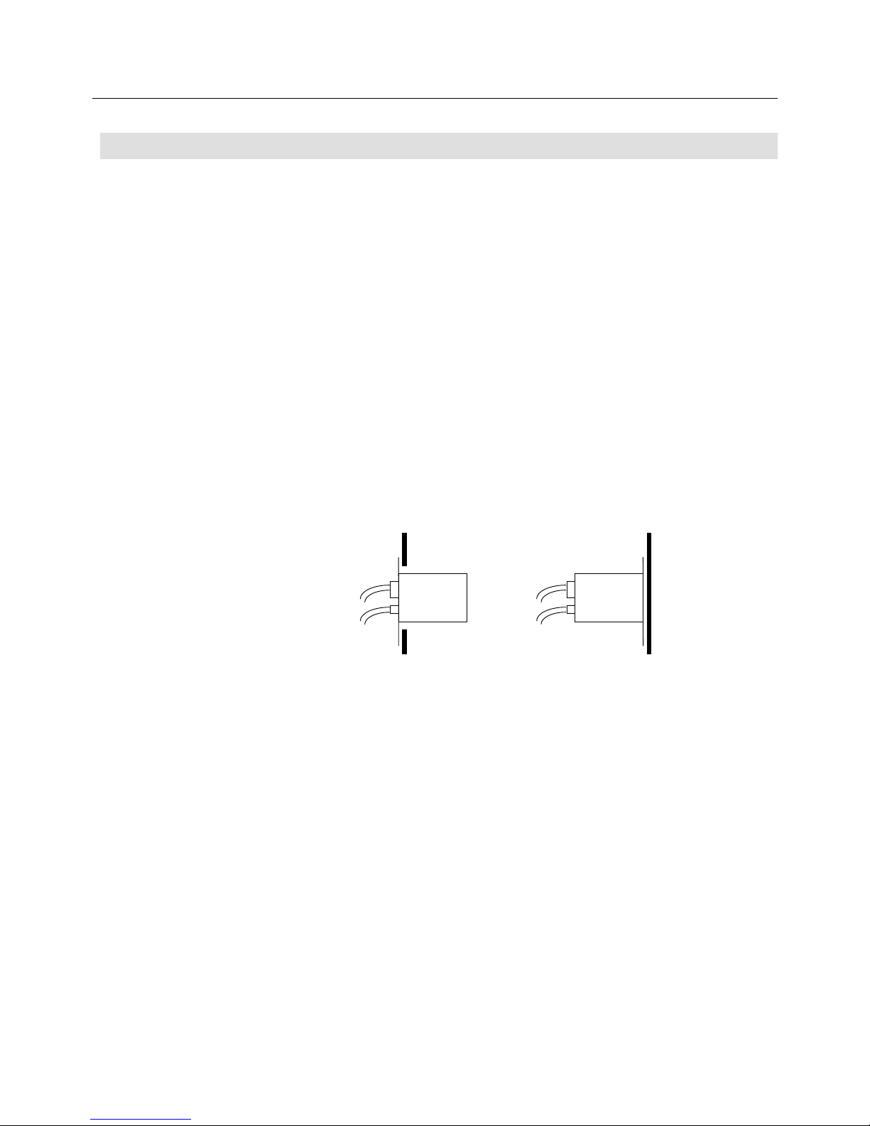
• Front or rear installation is selectable
Although only rear installation is usually available for a small Servo Amplifier, both front and rear
installations can be selected for the "PY2" or "PY" type.
(Rear installation is standard for the "PY2" on shipment.)
• All amplifier I/O wirings are changed to the connector type
The terminals of the high-voltage parts, which used to be the terminal board type on our conventional
"PY" and "PZ" series, are changed to the connector type. This improves operability when installing or
maintaining the Servo Amplifier.
• The leakage current has been reduced to about half that of conventional models
Measures to reduce leakage current are taken on the "PY2" amplifier, reducing it to about half that of
our conventional "PY" or "PZ" series.
When a 2 m cabtyre cable is used for the motor power line:
• 15A, 30A 0.5 mA or less
• 50A 1.5mA or less
• Additional tuning function
In addition to “Offline auto tuning” function, “Online auto tuning” and “Auto notch filter tuning” functions
are available.
Servo
Amplifier
Front
installation
Servo
Amplifier
Rear
installation
Page 37

2. FUNCTION, CHARACTERISTICS AND CONFIGURATION
2-7
• Supports various types of power supplies
The “PY2” Servo Amplifier supports 200 VAC 3-phase, 200 VAC single-phase and 100 VAC
single-phase types of power supplies.
Switching between 200 VAC 3-phase and 200 VAC single-phase is possible by simply changing the
parameters.
(Switching between 100 VAC single-phase and 3-/single-phase is impossible since they have different
hardware. A 100 VAC motor is also necessary.)
• High response
Features higher response than our conventional "PZ" type ("PY" and "PY2" have the same level of
response).
• High reliability and long life
Ensures long operation without failure thanks to circuit technologies accumulated from extensive
experience gained from our conventional models.
Page 38
2. FUNCTION, CHARACTERISTICS AND CONFIGURATION
2-8
Differences Between PY2 Amplifier and Sanyo Denki’s Conventional Models and
Precautions
• No fuse is built into the main power supply input section.
On our conventional PY, PZ, PE and PU models, fuses are built into the main power supply input
sections to save wiring and other reasons when a single axis is used. On the PY2 amplifier, however,
no fuse is built in since use of multiple axes is assumed and downsizing is the main theme of its
development.
(No fuse is built into the PV amplifier, one of our conventional models, as with the PY2.)
In order to protect the main power supply input section from overcurrent, connect a UL-approved circuit
breaker and a fast-blown fuse to the amplifier input section before operation.
• Fewer noise filters on the main and control power supply input sections
The number of noise filters has been reduced on the PY2 amplifier than on our conventional PY, PZ,
PE, PV and PU models. Noiseproofing, however, is the same as that on conventional models thanks
to improved internal circuits.
Although noiseproofing does not differ, after Sanyo Denki’s conventional amplifier in your system is
replaced with the PY2 amplifier, power supply noise which had been absorbed by the noise filters
inside the conventional amplifier may affect other peripherals. So, it is recommended that you attach
noise filters to the power supply (200 VAC).
• No regenerative resistor is built in. (The 50 A type amplifier normally has one built-in.)
On our conventional PY, PZ, PE, PV and PU models, regenerative resistors are built in (the power
absorbed differs depending on the model and the capacity).
On the “PY2A015*” and “PY2A030*” types, no regenerative resistor is built in.
(They incorporate regenerative processing circuits only.)
Externally connect regenerative resistors to systems requiring regenerative processing.
If no regenerative resistor is externally connected, it takes about five minutes to discharge the
capacitor after the main circuit power is turned off. Before maintaining the amplifier, make sure that
the "CHARGE" lamp on the front of the amplifier indicates that it has been discharged.
• The dynamic braking methods differ.
On the PY2 amplifier, the slowing-down revolution angle at the time of stopping by dynamic braking is
twice that of the PY, PZ and PE models in the worst case.
(The angle is the same between the PV and PY2. No dynamic brake is built into the PU model.)
• The forcible air cooling method is adopted for cooling power modules
(for the 30 A and 50 A types only).
On the “PY2A030*” and “PY2A050*” types, the forcible air cooling method is adopted to enable down
sizing and long life. So, the Servo Amplifier does not stop functioning even after the cooling fan stops
due to failure. To ensure long operation of the amplifier, check the motion of the fan during regular
inspection.
Page 39

2. FUNCTION, CHARACTERISTICS AND CONFIGURATION
2-9
• Sensor cable wiring
While the maximum length of the sensor cable wiring is 50 m for our conventional PY, PZ, and PE
models when a standard cable is used, the length is 30 m for the PY2 amplifier for sensor power
supply reasons (the maximum length is 25 m for the absolute encoder (ABS-E) type).
The permissible wiring distance can be extended to 50 m by using a cable with low conductor
resistance (a thick cable) or by increasing the number of wires. Contact us for details.
• External thermal input
While our conventional PY, PZ and PE models are equipped with input terminals capable of directly
connecting contact outputs of external thermals, the PY2 amplifier is not.
To connect an external thermal output to the amplifier, set the general-purpose input terminal to the
external thermal signal input before operation.
• AMP ready contact output
While our conventional PY, PZ and PE models are equipped with contact output terminals (AMP ready
output terminals) for magnetic contactors which control the amplifier main power on/off switching, they
are optional on the PY2 amplifier. For details, refer to "1.4 How to Read Model Numbers".
When no AMP ready output is used, turn the main power on and off using an external safety circuit.
• Analog monitor output
While analog monitor output is ± 10 V peak for our conventional PY, PZ and PE models, it is ± 3 V
peak for the PY2 amplifier. The resolution of the PY2 is also lower than that of conventional models.
Consult with us if high resolution is required for system evaluation or other purposes.
Page 40

2. FUNCTION, CHARACTERISTICS AND CONFIGURATION
2-10
Table 2-1 Comparison of PY2/PY and Sanyo's Other Series (for Reference)
PY2
amplifier
PY
amplifier
PZ and PE
amplifiers
PU
amplifier
PR
amplifier
RB
amplifier
PV
amplifier
Input
power
100 VAC
200 VAC
Single phase
3 phases
200 VAC
Single phase
3 phases
200 VAC
Single phase
3 phases
100 VAC
200 VAC
Single phase
200 VAC
Single phase
5 VDC, 38 V
5 VDC, 24 V
100 VAC,
Single phase
200 VAC,
Single phase
200 VAC
Single phase
Features ● Multi function
● High response, high
performance
● Small & compact
● Easy connection due
to adopting
connector method
● Multi function
● High response,
high
performance
● Multi function
● High response,
high
performance
● Small & compact
● Easy connection
due to adopting
connector
method
● Data
transmission
servo
(Direct input of
velocity,
acceleration and
feed data.
Easy operation
using PC or
CPU.)
● High cost
performance
● Downsizing
● Easy system
design
● Data
transmission
servo
(Direct input of
velocity,
acceleration and
feed data.
Easy operation
using PC or
CPU.)
● High cost
performance
● Downsizing
● Easy system
design
● Small & compact
● Wide range of
interface
• Position,
velocity and
torque
command
• Serial
command
(RS-485)
• Contact input
operation
command
● Easy connection
due to adopting
connector
method
Motor
combined
P1 series
0.3 to 2 kW
P2 series
1 to 2 kW
P3 series
30 to 750 W
P5 series
30 to 1000 W
P6 series
0.5 to 1.5 kW
P8 series
0.75 to 1.2 kW
P1 series
0.3 to 5.5 kW
P2 series
1 to 5 kW
P3 series
30 to 750 W
P5 series
30 to 1000 W
P6 series
0.5 to 15 kW
P8 series
0.75 to 4.5 kW
P1 series
0.3 to 5.5 kW
P2 series
1 to 5 kW
P3 series
30 to 750 W
P5 series
30 to 1000 W
P6 series
0.5 to 15 kW
P8 series
0.75 to 4.5 kW
P3 series
30 to 750 W
P5 series
30 to 1000 W
P3 series
30 to 750 W
P5 series
30 to 1000 W
Robust-syn motor
Equivalent to 10 to
600 W
P3 series
30 to 750 W
P5 series
30 to 1000 W
Sensor Wiring-saved
incremental
ANS-R II
ABS-E
ABS-E.S1
Wiring-saved
incremental
ABS-R II
ABS-E
Wiring-saved
incremental
ABS-R II
ABS-E
Wiring-saved
incremental
ABS-R II
Wiring-saved
incremental
Incremental
(200P/R, 800P/R)
Wiring-saved
incremental
ABS-R II
ABS-E
I/F Pulse train input
Analog input
Serial input
Pulse train input
Analog input
Serial input
Pulse train input
Analog input
Serial input
Pulse train input or
analog input
Centronics-based
8-bit parallel data
input
Centronics-based
8-bit parallel data
input
Serial command
(RS-485),
pulse train input
or analog input
Built-in
functions
● Regenerative
processing circuit
(without internal
regenerative resistor)
● Auto tuning
● Electronic gear
● Remote operator
● Vibration restraining
function
● Dynamic brake
● Holding brake
excitation timing
output
● Rush prevention
● Control mode
switching
● Internal velocity
command function
● Gain changeover
using a rotary switch
● Gain changeover
● Personal computer
interface functions
● Regenerative
processing
● Auto tuning
● Electronic gear
● Remote operator
● Vibration
restrain-ing
function
● Dynamic brake
● Holding brake
excitation timing
output
● Rush prevention
● Discharge circuit
● Control mode
switching
● Internal velocity
command
function
● Gain
change-over
using a rotary
switch
● Gain
changeover
● Personal
computer
interface
functions
● Regenerative
processing
● Auto tuning
● Electronic gear
● Remote operator
● Vibration
restraining
function
● Dynamic brake
● Holding brake
excitation timing
output
● Rush prevention
● Discharge circuit
● Regenerative
processing
● Auto tuning
● Electronic gear
● Remote operator
● Built-in pattern
generator
● Rush prevention
● Discharge circuit
● Built-in pattern
generator
● Rush prevention
● Discharge circuit
● Regenerative
processing
● Vibration
restraining
function
● Dynamic brake
● Rush prevention
Measures
for
overseas
standards
TÜV recognition to be
obtained
UL recognition to be
obtained
TÜV recognition
obtained
UL recognition
obtained
TÜV recognition
obtained
(PE type only)
TÜV recognition
obtained
TÜV recognition
obtained
TÜV recognition
obtained
UL recognition
obtained
Page 41
2. FUNCTION, CHARACTERISTICS AND CONFIGURATION
2-11
2.3 Characteristics of Servomotor
• Wide range of models (67 types in total)
P1 series: from 0.3 to 5.5 kW (15 types) P2 series: from 1 to 5 kW (14 types)
P3 series: from 30 to 750 W (6 types) P5 series: from 30 W to 1000 W (15 types)
P6 series: from 0.5 to 7 kW (11 types) P8 series: from 0.75 to 4.5 kW (6 types)
• High-speed motor
Maximum speed of 2000 min
−
1
and 3000 min
−
1
for P1
Maximum speed of 3000 min
−
1
and 4500 min
−
1
for P2
Maximum speed of 4500 min
−
1
for P3 and P5
Maximum speed of 3000 min
−
1
for P6 and P8
The above enables the positioning time to be shortened.
(For P1, P6/P8 series motor with output of 4.5 kW or above, however, maximum speed is little lower.)
• Compatibility
Compatible with the conventional models.
• Compatible with various sensors
Compatible with the wiring-saved incremental encoder, the ABS-E absolute sensor (encoder) or the
ABS-R II absolute sensor (the settings inside the amplifier differ depending on sensor types).
Table 2-2 Comparison of PY2 and PY Servomotor (for reference)
P1 series
(high rigidity)
P2 series
(low inertia)
P3 series
(low inertia)
P5 series
(high rigidity)
P6 series
(high rigidity)
P8 series
(flat type)
Features ● High servo
performance
● Compatible with
"861" motor
● High inertia
● Series expanded
● Flange size
□100 added
● Down-sizing
80% smaller than
our conventional
models
● Low inertia
● High power rate
● Successor to "862"
series
● Upper capacity
model of
P3 series
● Down-sizing
40% smaller than
our conventional
models
● Low inertia
● High power rate
● Down-sizing
50% smaller than
our conventional
models
● Medium inertia, high
rigidity
● Compatible with
"865Z" motor
● Flange size
□35 and
□42 added
● Down-sizing
70% smaller than
our conventional
models
● Medium inertia, high
rigidity
● Upper capacity
model of P5 series
● Compatible with
“861” motor
● Supplements
P8 series
● Down-sizing
50% smaller than
our conventional
models
● Medium inertia,
super flat type
● Compatible with
"868Z" motor
● Down-sizing
70% smaller and
60% flatter than our
conventional models
Rated
output
0.3 to 5.5 kW
(15 types)
1 to 5 kW
(14 types)
30 to 750 W
(6 types)
30 to 1000 W
(15 types)
0.5 to 7 kW
(11 types)
0.75 to 4.5 kW
(6 types)
Sensor ● Incre.
● Absolute
ABS-E
● Incre.
● Absolute
ABS-E
ABS-R II (R III)
● Incre.
● Absolute
ABS-R II (R III)
● Incre.
● Absolute
ABS-E
ABS-R II (R III)
● Incre.
● Absolute
ABS-E
ABS-R II (R III)
● Incre.
● Absolute
ABS-E
ABS-R II (R III)
Waterproof ● IP67 ● IP67 ● IP40 (IP55 option) ● IP55
(□55 to □86)
● IP55
(□35 to □42)
(IP55 option)
● IP67 ● IP67
Holding
brake
● Standard
specifications
(24 V, 90 V)
● Standard
specifications
(24 V, 90 V)
● Standard
specifications
(24 V, 90 V)
●Standard
specifications
(24 V, 90 V)
●Standard
specifications
(24 V, 90 V)
●Standard
specifications
(24 V, 90 V)
Oil seal ● Standard
specifications
● Standard
specifications
● Optional ● Standard
specifications
(□54 to □86)
● Optional
(□35 to □42)
● Standard
specifications
● Standard
specifications
Measures
for CE
● TÜV obtained ● TÜV obtained ● TÜV obtained ● TÜV obtained ● TÜV obtained ● TÜV obtained
Page 42

3. SERVO SYSTEM CONFIGURATION
3-1
SERVO SYSTEM CONFIGURATION
3.1 Block Diagram.............................................................................. 3-2
3.2 External Mounting and Wiring Diagram ....................................... 3-2
3.3 Names of Servo Amplifier Parts................................................... 3-3
3.3.1 PY2A015/030 .................................................................... 3-3
3.3.2 PY2E015/030 .................................................................... 3-4
3.3.3 PY2A050 ........................................................................... 3-5
3.4 Optional Peripheral Equipment List.............................................. 3-6
Page 43
3. SERVO SYSTEM CONFIGURATION
3-2
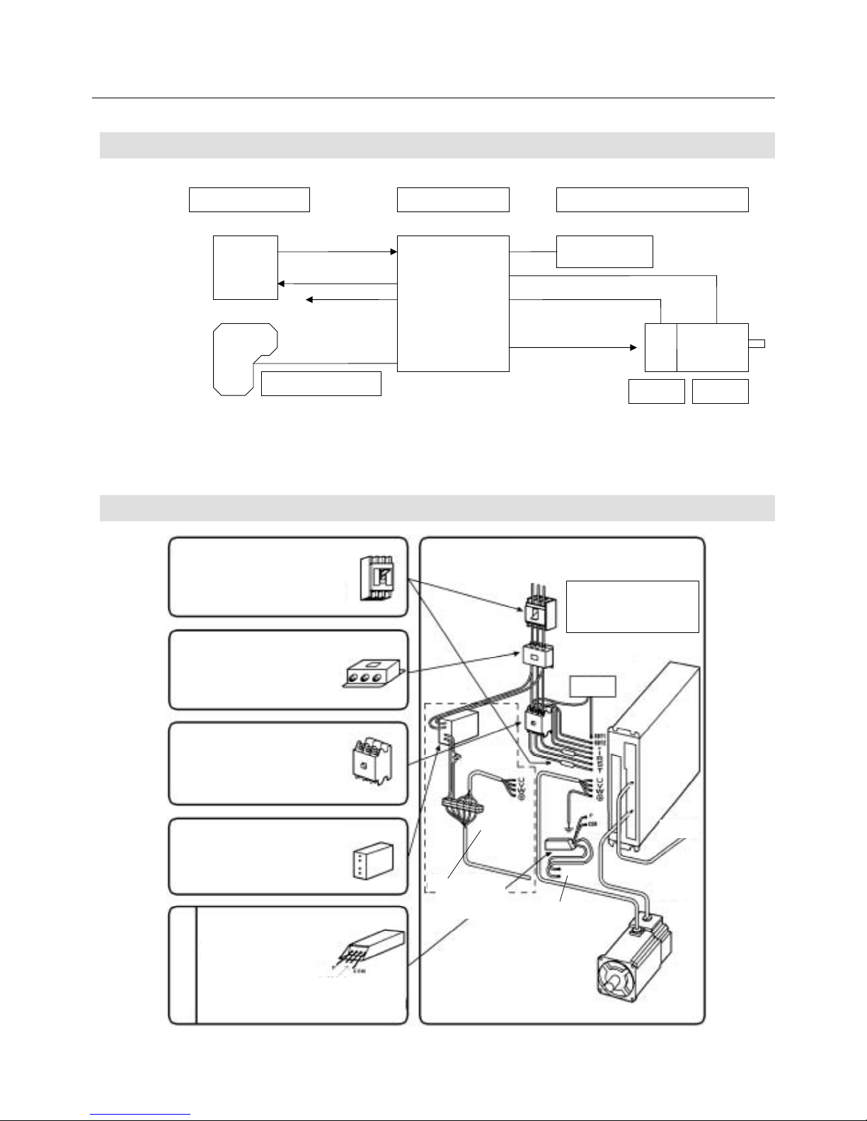
3.1 Block Diagram
Fig. 3-1 System Configuration Schematic Diagram
3.2 External Mounting and Wiring Diagram
Optional
Use one when load with
large inertial is to be
operated or in other
necessary cases.
External regenerative
resistor
DC power supply for brake
Used when the Servomotor is equipped
with a brake.
Magnetic contactor (MC)
Turns the Servo Amplifier power on and
off. Install a spark killer on it.
(Equivalent to CRE-50500 of Okaya
Electric Industries Co., Ltd.)
Noise filter
Install a filter equivalent to the LF series
of Tokin Corporation to prevent
common mode noise and normal mode
noise.
Circuit breaker, fuse
Used to protect the power line.
On the “PY2” Servo Amplifiers, no fuse is
built in. Be sure to connect a fast-blown
fuse of the capacity indicated in the
external connection diagram.
To
controller
Power supply:
200 VAC 3φ 50 Hz/60 Hz
200 VAC 1φ 50 Hz/60 Hz
100 VAC 1φ 50 Hz/60 Hz
See Fig. 6-1 in
“6 Operation”.
Brake control
relay
Safety
circuit
Encode
r
connector
Thermostat
contact output
Thermostat
contact output
The input power supply differs
depending on the specifications
of the amplifier and the motor.
Be sure to connect the power
supply within the specified range.
The wiring
required when the
motor is equipped
with a brake.
Fig. 3-2 External Mounting and Wiring Diagram
External regenerative resistorServo Amp.
Upper controller
Command
Feedback
Remote operator
Holding brake
excitation
timing output
Sensor Motor
AMP ready
Page 44
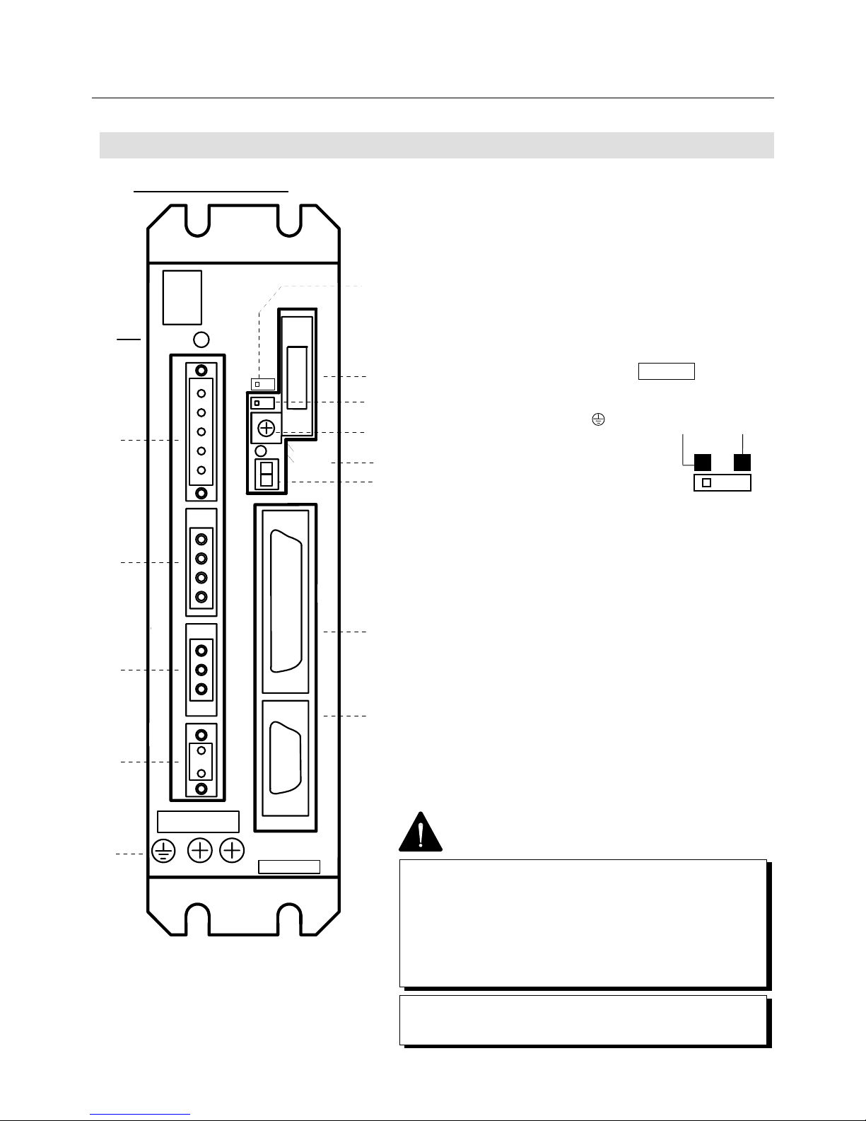
3. SERVO SYSTEM CONFIGURATION
3-3
CHARGE
POWER
CN
1
2
CNA
CNB
CND
CNC
CN
r
t
R
S
T
P
Y
U
V
W
RDY
1
2
RDY
PY2A015
1
2
3
4
5
6
7
8
9
10
11
12
13
OP
14
SELECT
POWER
N
11
13
12
10
OP
SELECT
POWER
RDY
2
RDY
1
PY2A015
CN
2
CNC
CNB
CND
CHA
W
V
U
N
CN
1
Y
P
T
S
R
r
t
CHARGE
POWER
6
5
4
3
2
1
9
8
7
14
Fig. 3-3 Front View of Servo Amplifier
(PY2A015A0)
3.3 Names of Servo Amplifier Parts
3.3.1 PY2A015/030
1 Main circuit power supply charge (CHARGE)
Indicates the charge of the smoothing capacitor of the
main circuit power supply.
2 Control & main power supply inputs (CAN)
Connect the control power supply (AC 200 V, single
phase) to the r and t terminals and the main power
supply (AC 200 V, 3-phase) to the R, S and T terminals.
3 Regenerative resistor connector terminal (CND)
Connect a regenerative resistor between the P and Y (or
COM) terminals.
4 Main circuit connector terminal (CNB)
Connect a motor power cable to it.
5 AMP ready output terminal (CNC)
Outputs a-contact when the control power supply is set
up and no alarm occurs (250 VAC, 2 A/30 VDC, 2 A).
6 Protective earth terminal ( )
Grounds an earth cable for
class 3 earthing.
7 Remote operator connector
8 HISTORY/GAIN changeover switch
Sets the rotary switch to the alarm history or gain
changeover function.
9 Rotary switch (SELECT)
Used to check the alarm history and change the gain.
10 5 V power supply set-up (POWER)
Comes on when the control power (r or t) is supplied.
11 7-segment LED
Indicates the status of the amplifier and the type of alarm
issued.
12 Interface connector (CN1)
Connected to a host controller, etc.
13 Sensor signal connector (CN2)
Connected to the sensor signal line from the motor.
14 Maintenance mode switch
Used for maintenance by Sanyo operator. So, do not
change the setting during general operation.
When the Servo Amplifier is used, be sure to set the
switch to the left when viewed from the front of the
amplifier. (It is hard to view from the front since hidden
in the Servo Amplifier case.)
HISTORY GAIN
Optional
14 Maintenance mode switch
• Be sure to set this switch to the normal mode for
operation (set it to the left when viewed from the front of
the amplifier).
• Never change the setting of this switch. If it is set to
the maintenance mode, the system malfunctions.
The 15 A and 30 A capacity amplifiers have different
dimensions (width).
Page 45
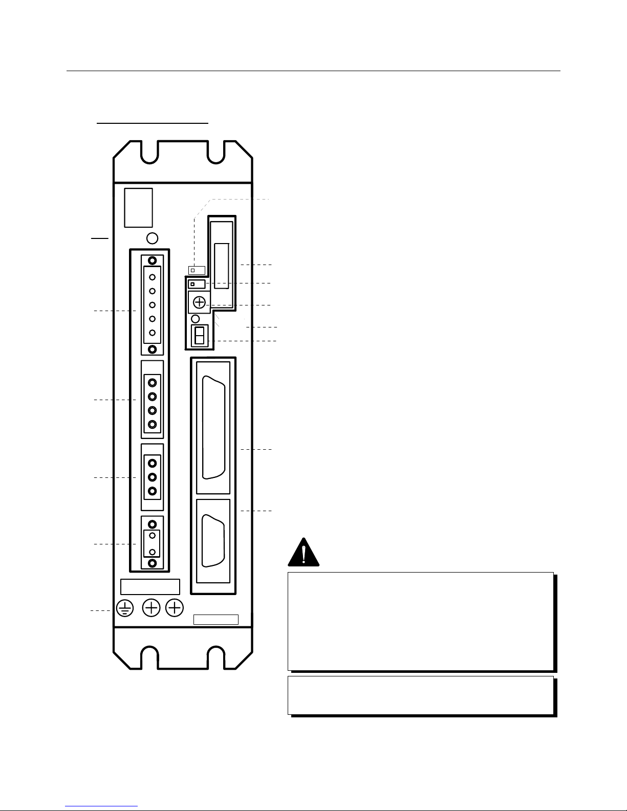
3. SERVO SYSTEM CONFIGURATION
3-4
CHARGE
POWER
CN
1
2
CNA
CNB
CND
CNC
CN
r
t
R
S
T
P
Y
U
V
W
RDY
1
2
RDY
PY2A015
1
2
3
4
5
6
7
8
9
10
11
12
13
OP
14
SELECT
POWER
N
OP
SELECT
POWER
RDY
2
RDY
1
PY2E015
CN
2
CNC
CNB
CND
CHA
W
V
U
N
CN
1
11
Y
P
T
S
R
r
t
CHARGE
POWER
6
5
4
13
12
3
2
1
10
9
8
7
14
3.3.2 PY2E015/030
Fig. 3-4 Front View of Servo Amplifier
(PY2E015A1)
2 Control and main power supply (CNA)
Connect the control power supply (100 VAC,
single-phase) to r and t, and the main power supply (100
VAC, single-phase) to R and T.
Same as 1 and 3 to 14, 200 VAC input type.
(Refer to 3.3.1 PY2A015/030.)
14 Maintenance mode switch
• Be sure to set this switch to the normal mode for
operation (set it to the left when viewed from the front of
the amplifier).
• Never change the setting of this switch. If it is set to
the maintenance mode, the system will malfunction.
The 15 A and 30 A capacity amplifiers have different
dimensions (width).
Page 46
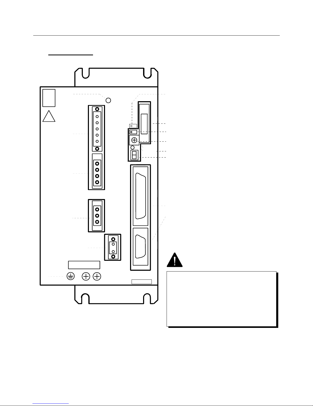
3. SERVO SYSTEM CONFIGURATION
3-5
CHARGE
CN
1
2
CNA
CNB
CND
CNC
CN
r
t
R
S
T
Y
U
V
W
RDY
1
2
RDY
PY2A050
1
2
3
4
5
6
7
8
9
10
11
12
13
OP
14
SELECT
POWER
N
X
P
PY2A050
CNC
6
5
RDY
2
RDY
1
CN
2
CNB
W
V
12
13
4
U
CN
1
Y
X
Y
P
CND
3
POWER
SELECT
OP
2
1
T
S
R
t
r
CNA
10
11
8
9
CHARGE
7
14
3.3.3 PY2A050
3 Regenerative resistor connecting terminal
(CND)
When a built-in regenerative resistor is
used, use it at the settings made on
shipment (i.e. short-circuit the P and X
terminals using a short-circuit bar).
When an external regenerative resistor is
used, remove the short-circuit bar from
across the P and X terminals and install a
regenerative resistor between the P and Y
terminals.
Same as 1, 2 and 4 to 14, PY2A015/030.
(Refer to 3.3.1 PY2A015/030.)
Fig. 3-5 Front View of Servo Amplifier
(PY2A050A4)
14 Maintenance mode switch
• Be sure to set this switch to the normal
mode for operation (set it to the left when
viewed from the front of the amplifier.)
• Never change the setting of this switch. If it
is set to the maintenance mode, the system
will malfunction.
Page 47

3. SERVO SYSTEM CONFIGURATION
3-6
3.4 Optional Peripheral Equipment List
The following optional peripheral devices are available for the PY2 Servo Amplifiers.
Please order as necessary.
● I/O connectors
The table below lists I/O connector plugs and housings.
(Connectors of standard shapes are listed as optional equipment.)
Connector List for PY2A (200 VAC input type)
Application Model No. Set contents Maker Maker’s model No.
10150-3000VE
AL-00385594 CN1 plug and housing Sumitomo 3M
10350-52A0-008
10120-3000VE
AL-00385596 CN2 plug and housing Sumitomo 3M
10320-52A0-008
AL-00329461-01 CNA plug Phoenix Contact MSTB2.5/5-STF-5.08
AL-00329458-01 CNB plug Phoenix Contact IC2.5/3-STF-5.08
AL-00329460-01 CNC plug Phoenix Contact MSTB2.5/2-STF-5.08
Single item
AL-00329459-01 CND plug Phoenix Contact IC2.5/4-STF-5.08
10150-3000VE
10350-52A0-008
10120-3000VE
Low-voltage
circuit connector
set
AL-00292309
CN1 or CN2 plug and
housing
Sumitomo 3M
10320-52A0-008
MSTB2.5/5-STF-5.08
IC2.5/3-STF-5.08
High-voltage
circuit connector
set
AL-00377169 CNA, CNB or CND plug Phoenix Contact
IC2.5/4-STF-5.08
10150-3000VE
10350-52A0-008
10120-3000VE
10320-52A0-008
MSTB2.5/5-STF-5.08
IC2.5/3-STF-5.08
PY2A015 and
PY2A030 (without
RDY output) set
AL-00382550
CN1 or CN2 plug and
housing
CNA, CNB or CND plug
Sumitomo 3M
Phoenix Contact
IC2.5/4-STF-5.08
PY2A015 and
PY2A030
(with RDY
output) set
AL-00382550
AL-00329460-01
CN1 or CN2 plug and
housing
CNA, CNB, CNC or
CND plug
Sumitomo 3M
Phoenix Contact
PY2A015 (built-in 10150-3000VE
Regenerative resistor) 10350-52A0-008
PY2A030 (built-in 10120-3000VE
Regenerative resistor) 10320-52A0-008
PY2A050(without MSTB2.5/5-STF-5.08
RDY output) set
AL-00393603
Sumitomo 3M
Phoenix Contact
IC2.5/3-STF-5.08
PY2A015 (built-in
Regenerative resistor)
PY2A030 (built-in
Regenerative resistor)
PY2A050 (with
RDY output) set
AL-00393605
CN1 or CN2 plug and
housing
CNA, CNB or CNC plug
Sumitomo 3M
Phoenix Contact
Page 48
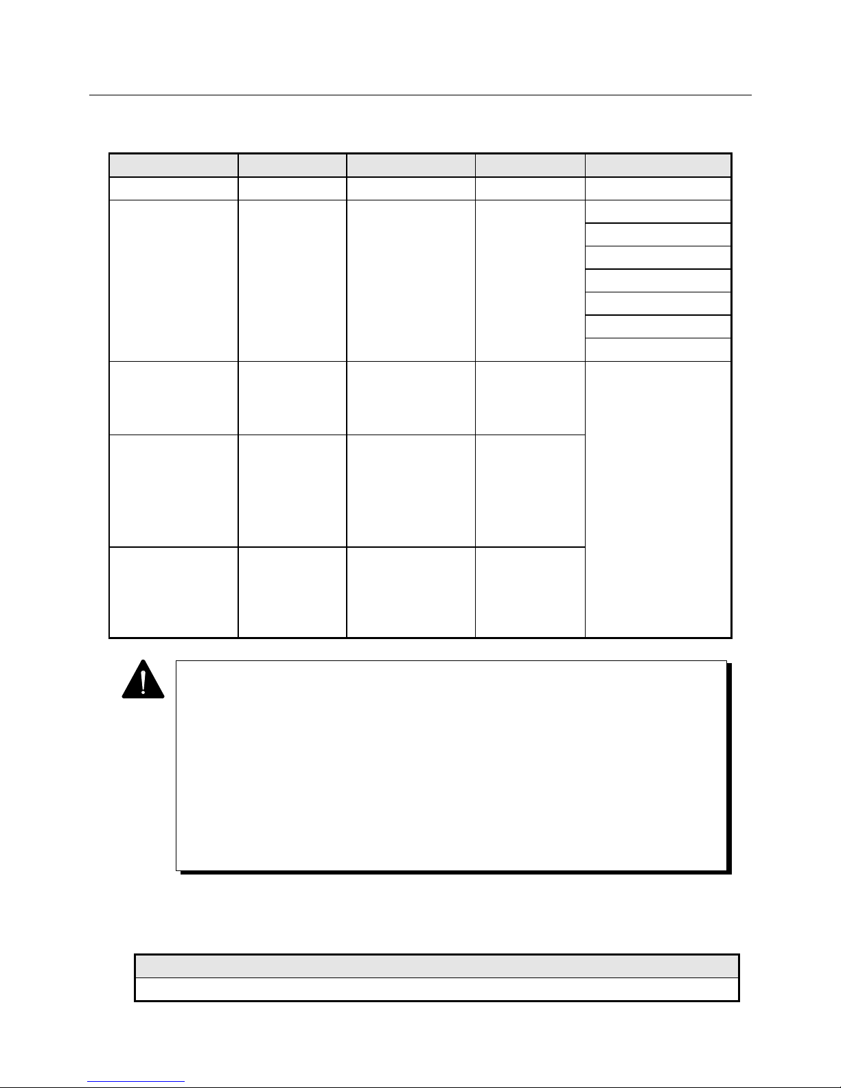
3. SERVO SYSTEM CONFIGURATION
3-7
Connector List for PY2E (100 VAC input type)
Application Model No. Set contents Maker Maker’s model No.
Single item AL-00329461-02 CNA plug Phoenix Contact MSTB2.5/4-STF-5.08
10150-3000VE
10350-52A0-008
10120-3000VE
10320-52A0-008
MSTB2.5/4-STF-5.08
IC2.5/3-STF-5.08
PY2E015 and
PY2E030 (without
RDY output) set
AL-00397841
CN1 or CN2 plug
and housing
CNA, CNB or CND
plug
Sumitomo 3M
Phoenix Contact
IC2.5/4-STF-5.08
PY2E015 and
PY2E030
(with RDY output)
set
AL-00397841
AL-00329460-01
CN1 or CN2 plug
and housing
CNA, CNB, CNC or
CND plug
Sumitomo 3M
Phoenix Contact
PY2A015 (built-in
Regenerative resistor)
PY2A030
(built-in
Regenerative resistor)
(without RDY output)
set
AL-00329461-02
AL-00329458-01
AL-00292309
CN1 or CN2 plug
and housing
CNA or CNB plug
Sumitomo 3M
Phoenix Contact
PY2A015 (built-in
Regenerative resistor)
PY2A030
(built-in
Regenerative resistor) (with
RDY output) set
AL-00329461-02
AL-00329458-01
AL-00329460-01
AL-00292309
CN1 or CN2 plug
and housing
CNA, CNB or CNC
plug
Sumitomo 3M
Phoenix Contact
● Remote operator
Connected to the Servo Amplifier to set various parameters or check the internal status.
Model No.
RP-001
• Although a commercially available plug not listed in the above table may be used, it may
not engage with the amplifier properly depending on its shape.
• Consult with us when using a plug or housing whose engagement with the amplifier is not
confirmed.
• The power supply input connector CNA models differ depending on the input power
supply voltage type (200 VAC or 100 VAC input).
• CND connector (IC2.5/4-STF-5.08) is normally attached to Servo Amplifier having an
amplifier capacity of 50 A.
• CND connector (IC2.5/4-STF-5.08) is normally attached to 15A and 30A Servo Amplifier
with built-in regenerative resistor.
Page 49
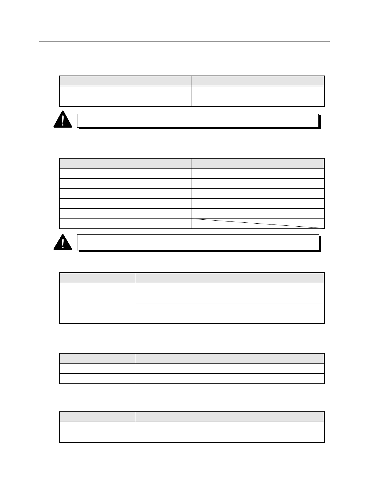
3. SERVO SYSTEM CONFIGURATION
3-8
● Personal computer interface
The following parts are available for communication with PC.
Model No. Remarks
AL-00356620-01 Specialized cable
SFY95-00 Communication program
● External regenerative resistor
Use one when load with large inertia is to be operated or in other necessary cases.
Model No. Model No.
REGIST-080W 100B REGIST-220W 20B
REGIST-080W 50B REGIST-500W 20B
REGIST-120W 100B REGIST-500W 14B
REGIST-120W 50B REGIST-500W 10B
REGIST-220W 100B REGIST-500W 7B
REGIST-220W 50B
● Cable
Only sensor cables are available. Terminals, however, are not treated.
Model No. Remarks
6879019-1 For wiring-saved incremental encoder (20 m or shorter)
6870010-1 For wiring-saved incremental encoder (20 m or longer)
For absolute encoder (ABS-E)
Absolute sensor (ABS-R II)
● Cannon connector
Use a connector to wire the Servo Amplifier and the motor.
Model No. Remarks
MS06B24-11S-16 Straight plug for the P1, P2, P6 or P8 motor power line.
MS06B20-29S-12 Straight plug for the P1, P2, P6 or P8 motor sensor line.
● Anti-noise parts
The following anti-noise parts are available.
Model No. Remarks
CRE-50500 Spark killer
R·A·V-781BXZ-2A Surge protector
The PC interface can be used only on Windows 95.
A type without a thermal (no "B" at the end of the model number) is also available.
Page 50

4. WIRING
4-1
WIRING
4.1 Applicable Wire Sizes .................................................................. 4-2
4.2 Specifications of Sensor Cable .................................................... 4-3
4.3 External Wiring Diagram .............................................................. 4-4
4.3.1 External Wiring Diagram (200 VAC Input Type) ................ 4-4
4.3.2 External Wiring Diagram (100 VAC Input Type) ................ 4-6
4.3.3 Sensor Connection Diagram (INC-E) ................................ 4-8
4.3.4 Sensor Connection Diagram (ABS-E) ............................... 4-9
4.3.5 Sensor Connection Diagram (ABS-RII) ............................ 4-10
4.3.6 Sensor Connection Diagram (ABS-E.S1).......................... 4-11
4.4 Connector Terminal Arrangement
Input/Output Signal Diagram........................................................ 4-12
4.4.1 CN1: Interface Connector ................................................. 4-12
4.4.2 CN2: Sensor Connector .................................................... 4-13
4.5 Wiring Procedure ......................................................................... 4-15
4.6 Precautions on Wiring.................................................................. 4-16
4.6.1 Recommended Surge Protector ........................................ 4-17
4.6.2 CN1 & CN2 Shielding Procedure ...................................... 4-18
4.6.3 Typical CN2 Compression Insert Application ....................4-20
Page 51
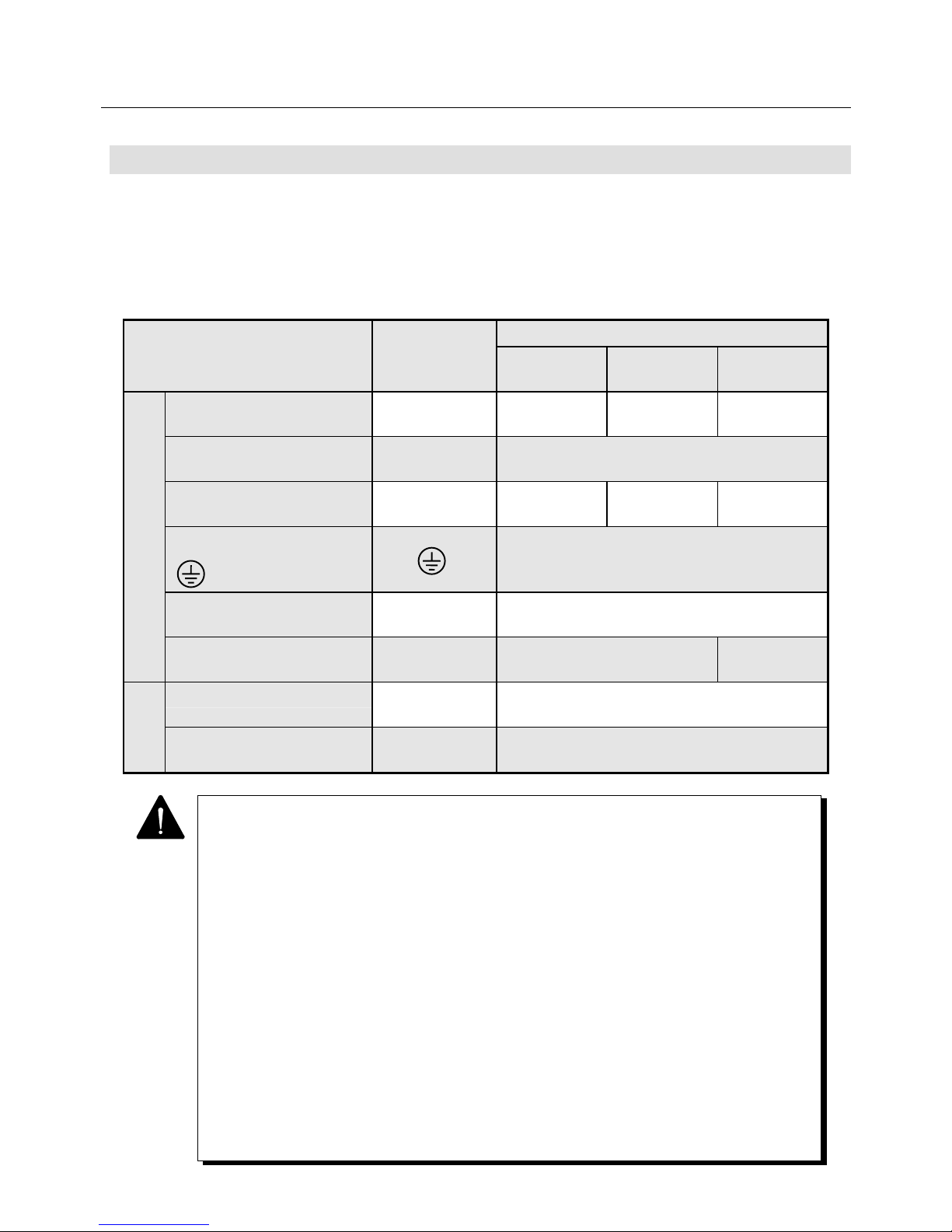
4. WIRING
4-2
4.1 Applicable Wire Sizes
• The table below shows typical sizes of external terminals and wires used for the Servo Amplifier.
• Select the wire to use and its size based on the wiring distance, operation environment and current
capacity.
• Table 4-1 assumes that the rated current flows on three lead wiring harnesses at an ambient
temperature of 104°F (40°C).
Table 4-1 Applicable Wire Sizes
Model
Example of applicable wire size
External terminal name
Terminal code
PY2A015
PY2E015
PY2A030
PY2E030
PY2A050
Main circuit power supply
input terminal
CNA
(R. S. T)
Equivalent to
AWG16
Equivalent to
AWG14
Equivalent to
AWG12
Control power supply input
terminal
CNA
(r. t)
Equivalent to AWG16
Motor connector terminal
(power line)
CNB
(U, V, W)
Equivalent to
AWG16
Equivalent to
AWG14
Equivalent to
AWG12
PE (protective earth) terminal
( )
Equivalent to AWG14
AMP ready output terminal
(optional)
CNC
(RDY1, RDY2)
Equivalent to AWG20
Regenerative resistor
connection input terminal
CND
(P, X, Y)
Equivalent to AWG16 Equivalent to
AWG14
I/O signal connector CN1 AWG24 or greater
(A twisted pair lump shielded wire is partly used.)
Sensor signal
connector
CN2 AWG 24 or greater twisted pair lump
shielded wire
Signal
circuit
1 For bundling wires or putting them in a duct, take the allowable current reduction ratio of
the wires into consideration.
2 When the ambient temperature is high, the life will be shortened due to thermal
degradation. In this case, use a heat-resistant vinyl cable.
3 The size of the wire to be connected to the main circuit power supply input terminal or
motor connecting terminal can be smaller than listed in the above table, depending on
the capacity of the Servomotor. (Use a wire of suitable size, referring to Power Supply
Capacity in Section 9.)
4 We prepare an optional sensor signal line connector cable, which can be purchased by
specifying the model number.
5 It is recommended to use an "insulation sleeve-equipped bar terminal" if a certain
insulation distance is required to be secured between main circuit wires or between
main and signal circuit wires.
(This terminal cannot be used when the wire used is AWG12 or greater.)
6 The recommended tightening torque of the jack screw (screw) in the shell
(connector cover : 10320-52A0-008) is 0.196±0.049N・m(2.0±0.5kgf・cm).
We ask you to tighten with this torque.
7 The jack screw with a stopper can prevent over-tightening. The product no. (with a
stopper) is 3342-26 and the recommended tightening torque is 0.441±0.049N・m
(4.5±0.5kgf・cm).
Page 52
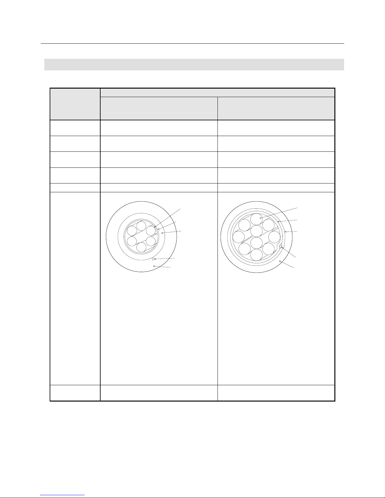
4. WIRING
4-3
4.2 Specifications of Sensor Cable
Table 4-2 Specifications of Cable
Specifications
Wiring-saved incremental encoder
(INC-E : wiring distance 20 m or less)
Wiring-saved incremental encoder
(INC-E : wiring distance 20 m to 30 m)
Absolute encoder (ABS-E, ABS-RII)
Connecting
Method
By soldering By soldering
Maker names Tonichi Cable, Ltd. Tatsuta Electric Wire and
Cable Co., Ltd.
Approximate
specification
6-pairs × 0.2 mm2
(Tinned annealed copper wire)
10-pairs × 0.2 mm2
(High-strength copper alloy twisted wire)
Finished outside
diameter
8.0 mm MAX 10.0 mm MAX
Bulk resistance 91 Ω /km MAX 123 Ω/km MAX
Internal
composition and
Lead color
対
押え巻
横線シールド
ド レイ ンワ イヤ
シース
1
2
3
4
5
6
1 : Red-Black (Twisted pair)
2 : Blue-Brown (Twisted pair)
3 : Green-Purple (Twisted pair)
4 : White-Yellow (Twisted pair)
5 : Skyblue-Pink (Twisted pair)
6 : Orange-Gray (Twisted pair)
対
押え巻テープ
銅箔糸編組
ドレインワイヤ
シース
1
2
3
4
5
6
7
8
9
10
しゃへい
1 : Blue-White (Twisted pair)
2 : Yellow-White (Twisted pair)
3 : Green-White (Twisted pair)
4 : Red-White (Twisted pair)
5 : Purple-White (Twisted pair)
6 : Blue-Brown (Twisted pair)
7 : Yellow-Brown (Twisted pair)
8 : Green-Brown (Twisted pair)
9 : Red-Brown (Twisted pair)
10 : Purple-Brown (Twisted pair)
Our available
specifications
Our Model No. 6879019-1,
No terminal treatment (without connector)
Our Model No. 6870010-1,
No terminal treatment (without connector)
Sheath
Binding tape
Copper foil
yarn mesh
shielding
Sheath
Drain wire
Pair
Drain wire
Striping
shield
Binding tape
Pair
6
5
4
3
2
9
8
6
7
2
5
1
3
4
10
Page 53
4. WIRING
4-4
1 When applicable cables are used, the permissible distance between the Servo Amplifier
and the motor (sensor) is as follows:
• Wiring-saved incremental encoder (INC-E): 20 m max. when 6 pairs of cables of
91 Ω/km or less are used.
• Wiring-saved incremental encoder (INC-E): 30 m max. when 10 pairs of cables of
123 Ω/km or less are used.
• Absolute encoder (ABS-E): 25 m max. when 10 pairs of cables of 123 Ω/km or less
are used.
• Absolute sensor (ABS-R II): 30 m max. when 10 pairs of cables of 123 Ω/km or less
are used.
2 The permissible wiring distance can be extended to 50 m by using a cable with low
conductor resistance (a thick cable) or increasing the number of wires. Contact us for
details.
3 When ordering cables from us, please specify our Model Nos. and lengths.
4 Before using these cables to any moving elements, please consult with us.
Page 54
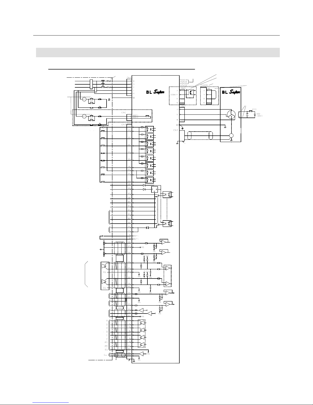
4. WIRING
4-5
4.3 External Wiring Diagram
4.3.1 External Wiring Diagram (200 VAC Input Type)
Fig. 4-1 (a) External Wiring Diagram (200 VAC Input Type)
AC power supply 3φ
200 to 230 V
50/60 Hz
User unit
En-
coder
SERVO
Orange (yellow)
Holding brake
(for the type with
a brake only)
Short bar
Note 15)
SERVO AMPLIFIER
Note 3)
Note 16)
Note 14)
Note 17)
Start ready ON
System error
System error
DC 5 V to 24
Emergency
sto
p
Emergency
sto
p
Servo ON
Alarm reset
Current limit permit
Note 9) Forward revolution
overtravel
Note 9) Backward revolution
overtravel
Note 10) General-purpose
input
Note 10) General-purpose
input
Note 10) General-purpose
input
Note14) 12 VDC to 24 V
Note 11) General-purpose output
Note 11) General-purpose output
Start ready complete output
Holding brake relay excitation
timing output
A
LM1
ALM2
Note 12) Alarm output
ALM4
ALM8
Output common
Note 13) Forward revolution
current limit
Note 18) Lithium battery
3.6 VDC
Note 13) Backward revolution
current limit
Note 8) Line driver 26LS31
Note 8) Velocity command input
Note 8) Torque compensation/
command input
Monitor 1
Monitor 2
Monitor common
Note 18) Encoder signal
Open collector output
Plug: 10150−3000 VE, Shell: 10350-52A0-008
Forward
revolution
pulse
Backward
revolution
pulse
Position
command
pulse input
Start ready OFF
Start ready OFF
Note 19)
Note 14) 5 VDC
Built-in type
regenerative resistor
When connecting an external
regenerative resistor
Note 4) PY2A050 built-in type
regenerative resistor
Regenerative resistor
Note 4)
Note 6) Red
White
Black
(Green/yellow)
Green
Note 7)
Plug : 10120-3000VE,
Shell : 10320-52A0-008
Note 5)
Sensor connector
Series regulator
Note 2)
Line receiver:
26LS32
Line driver: 26LS31
Note 5)
Page 55
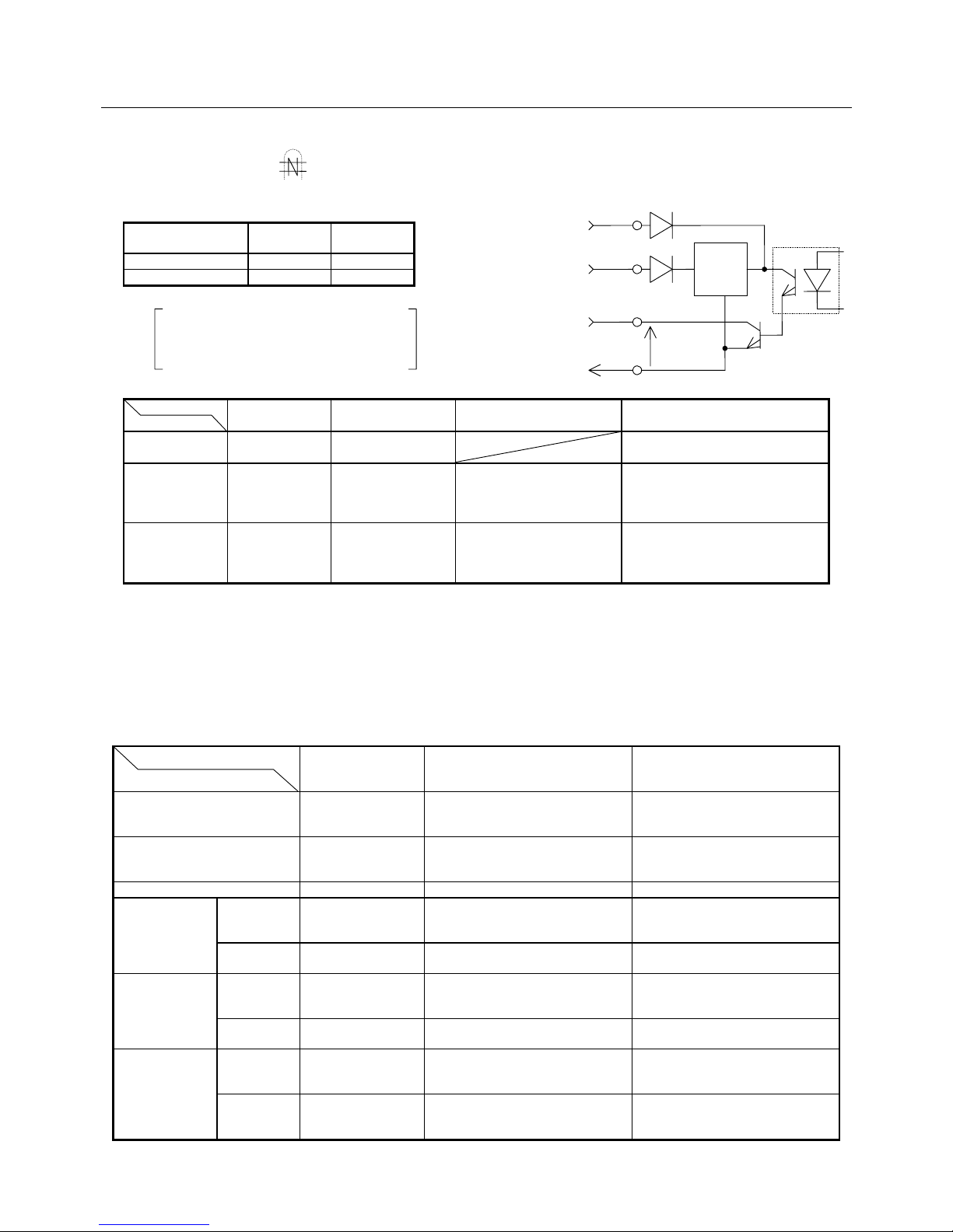
4. WIRING
4-6
Note 1) : For the parts marked , use a twisted pair shielded cable.
Note 2) : Select the power supply from the two types, 5 V or 12 V to 24 V.
CN1 -
38 pin
CN1 -
49 pin
5 V used Connected Open
12 to 24 V used Open Connected
Note 3) : RDY (RDY1 or 2 terminal) output is optional.
RDY (RDY1 or 2 terminal) is a contact output.
Contact rating: 250 VAC, 2 A
30 VDC, 2 A
Inductive load: COSφ = 0.4, L/R = 7 mS
Note 4) :
Amp. capacity
CND terminal
*1
Built-in type
regenerative resistor
Use of built-in type
regenerative resistor
*2
Method of connecting external
regenerative resistor *3
15, 30 A
(Normal)
P, Y (or COM), N None Connect it between
the P and Y (or COM) terminals.
30 A
(Special)
P, Y, N Equipped Same as default connection.
Connect it between
the P and Y terminals.
Connect it between
the P and Y terminals after removing
the wiring connected between
the P and Y terminals.
*4
50 A
(Normal)
P, Y, X, N Equipped Same as the default.
Short-circuit the P and X
terminals using a short-circuit
bar.
Connect it between the P and X
terminals after removing the
short-circuit bar across
P and X terminals.
*1 : The N terminal is for maintenance (high-voltage circuit). So, do not wire the N terminal.
*2 : The thermostat contact output of the built-in regenerative resistor is connected inside the amplifier.
*3 : A thermostat for the external regenerative resistor shall be built into the user device, or connected to the external overheat detection
input to protect the resistor.
*4 : Be careful not to bring the removed wire into contact with the conductive parts.
Note 5) : Refer to 4.6.2 CN1 & CN2 Shielding Procedure.
Note 6) : Motor connection differs to the motor specifications. The indications of red, white, black, green and orange apply when the motor
power and brake lines are the lead type. When they are the cannon plug type, connect them according to the motor specifications.
Note 7) : For how to wire the sensor connector, refer to the sensor wiring diagram.
Note 8) : The functions of command input differ depending on control modes.
Command input terminal
Control mode
Position command
pulse input
Velocity command input
Torque command input
Position control type Position command
pulse input
Velocity addition input is assumed
depending on the setting of Func1.
Torque compensation input is
assumed depending on the setting of
Func1.
Velocity control type − Velocity command input Torque compensation input is
assumed depending on the setting of
Func1.
Torque control type − − Torque command input
Velocity/torque
switch type
No switching − Velocity command input Torque compensation input is
assumed depending on the setting of
Func1.
During
switching
− − Torque command input
Position/torque
switch type
No switching Position command
pulse input
Velocity addition input is assumed
depending on the setting of Func1.
Torque compensation input is
assumed depending on the setting of
Func1.
During
switching
− − Torque command input
Position/velocity
switch type
No switching Position command
pulse input
Velocity addition input is assumed
depending on the setting of Func1.
Torque compensation input is
assumed depending on the setting of
Func1.
During
switching
− Velocity command input Torque compensation input is
assumed depending on the setting of
Func1.
5 V input
38
12 V to 24 V
input
Max.
30 VDC
O I
49
G
5 V input:
10 mA max.
12 to 24 V input:
50 mA max.
Output common
Page 56
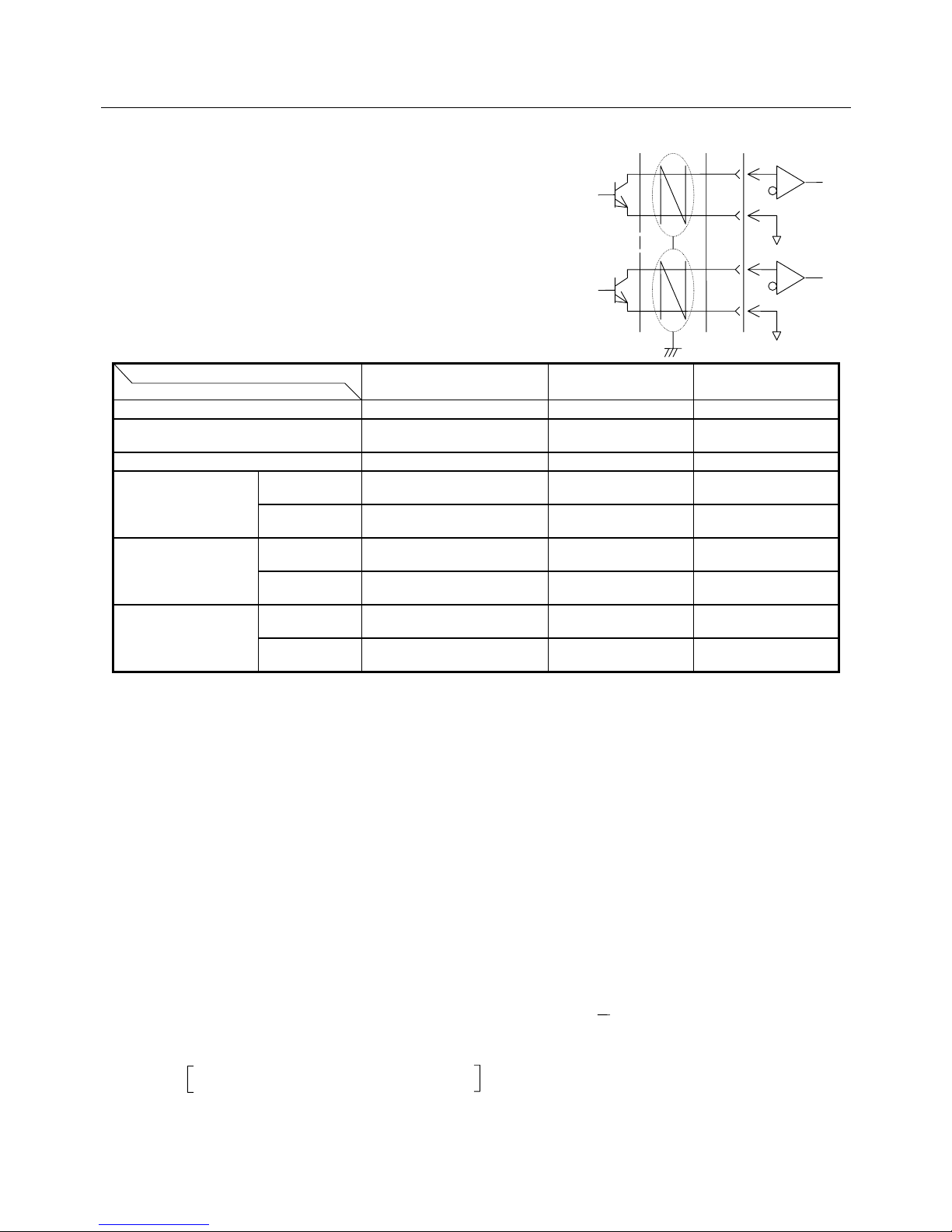
4. WIRING
4-7
For the details of the control mode and Func1 setting, refer to
the user's manual.
The polarity of command input can be reversed.
Refer to the figure on the right when connecting the position
command pulse input to the open collector output.
Note 9) : Forward/backward revolution overtravel input
By setting Func0, this function can be deleted or set
to the a-contact input.
Note 10) : The function of the general-purpose input can be
selected from the table below.
General-purpose input terminal
Control mode
34 pin 35 pin 36 pin
Position control type Deviation clear (1) (1)
Velocity control type Internal velocity command,
revolution direction input
(2) (2)
Torque control type
−
(3) (3)
Velocity/torque switch
type
No switching Internal velocity command,
revolution direction input
Control mode switching
input or (2).
Control mode switching
input or (2).
During switching
−
Control mode switching
input or (3).
Control mode switching
input or (3).
Position/torque switch
type
No switching Deviation clear Control mode switching
input or (1).
Control mode switching
input or (1).
During switching
−
Control mode switching
input or (3).
Control mode switching
input or (3).
Position/velocity switch
type
No switching Deviation clear Control mode switching
input or (1).
Control mode switching
input or (1).
During switching Internal velocity command,
revolution direction input
Control mode switching
input or (2).
Control mode switching
input or (2).
(1) : Functions can be selected among external overheating detection, proportional control, command multiplication and command pulse
inhibit.
(2) : Functions can be selected among external overheating detection, proportional control, zero clamp and internal setting velocity select.
(3) : Available as the external overheating detection input function.
In addition to the above, it can also be set as the gain switch input.
One pin can be set to have several or no functions.
For details, refer to the operation manual.
Note 11) : General-purpose output
By setting Func4, functions can be selected among current limit, low velocity, high velocity, velocity match, positioning complete and
command receive enabled. Output logic can also be selected.
Note 12) : Alarm output
Output alarm state using codes. It can also be output using bits by setting.
Note 13) : Forward/backward revolution current limit input
By changing the setting, both forward and backward revolution currents can be limited using the revolution current limit or the
backward revolution current can be limited using positive voltage. It can also be limited using the internal setting.
Note 14) : Your are required to prepare the power. Either of the inputs can be selected.
Note 15) : The R, S, T, r, t, RDY1, RDY2, P, Y (or COM), N, U, V and W terminals are high-voltage circuits and the others are low-voltage
circuits.
For the wiring-related reason, allow sufficient distance between high- and low-voltage circuits.
Note 16) : We recommend that a UL-approved earth leakage breaker be used that complies with IEC or EN standard.
Note 17) : Do not wire the S phase for a single-phase power amplifier.
Note 18) : The lithium battery connector terminals (1 and 2 pins) and encoder signals PS and PS (9 and 10 pins) are available when your
encoder is the absolute type (ABS-E, ABS-RII or ABS-E.S1).
Note 19) : Be sure to install the following types of UL-approved fuses for the main circuit power supply input.
Amplifier capacity 15 A, 30 A : 30 A fast-blown type
Amplifier capacity 50 A : 50 A fast-blown type
Note 20) : Make sure to connect SG (signal ground) for difference input signal (line driver of position command/ line driver of dividing output),
or wrong operation and breakage may occur.
Fig. 4-1 (b) External Wiring Diagram (200 VAC Input Type), Precautions
26
47
Forward
revolution pulse
Backward
revolution pulse
28
48
Page 57
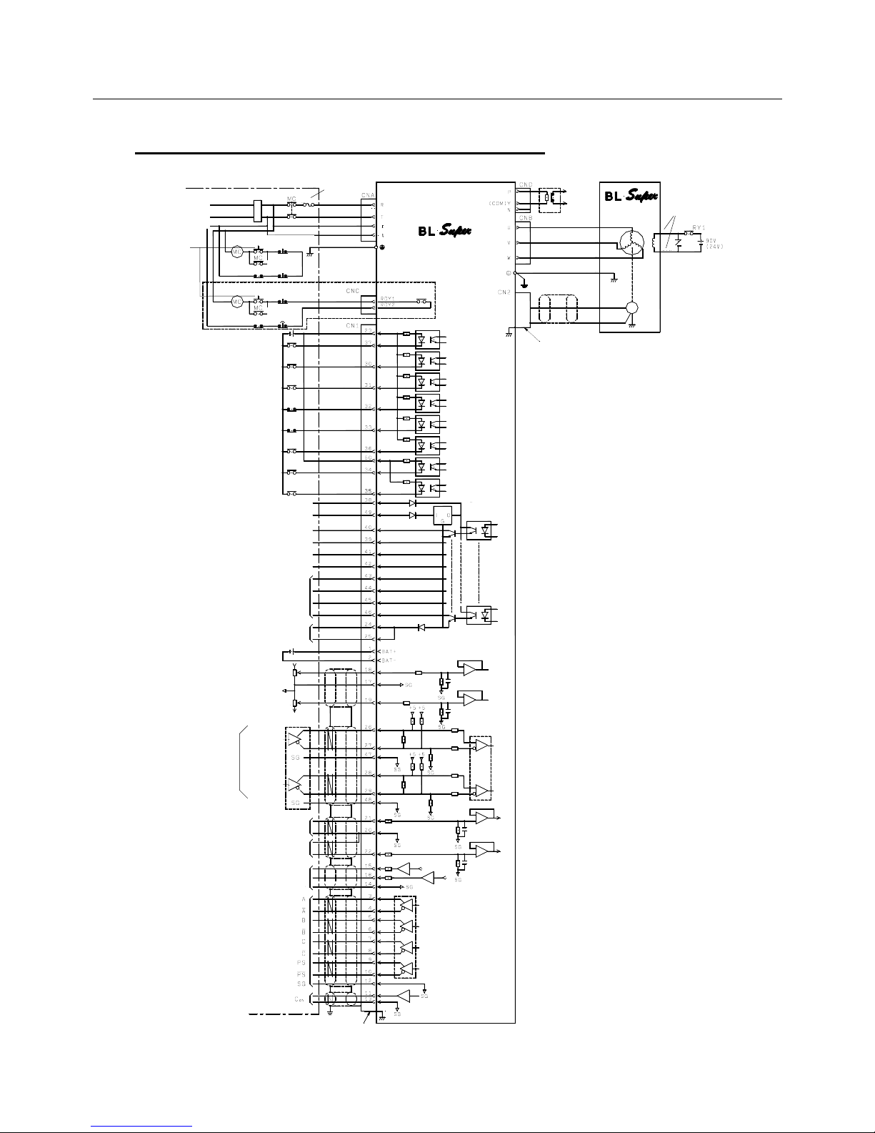
4. WIRING
4-8
4.3.2 External Wiring Diagram (100 VAC Input Type)
Fig. 4-2 (a) External Wiring Diagram (100 VAC Input Type)
AC power supply 3φ
100 to 115 V
50/60 Hz
User unit
En-
coder
SERVO
Orange (yellow)
Holding brake
(for the type with
a brake only)
Note 15)
SERVO AMPLIFIER
Note 3)
Note 16)
Note 14)
Start ready ON
+10%
−15%
System error
System error
DC 5 V to 24
Emergency
sto
p
Emergency
sto
p
Servo ON
Alarm reset
Current limit permit
Note 9) Forward revolution
overtravel
Note 9) Backward revolution
overtravel
Note 10) General-purpose
input
Note 10) General-purpose
input
Note 10) General-purpose
input
Note14) 12 VDC to 24 V
Note 11) General-purpose output
Note 11) General-purpose output
Start ready complete output
Note 13) Forward revolution
current limit
Note 13) Backward revolution
current limit
Note 8) Line driver 26LS31
Note 8) Velocity command input
Note 8) Torque compensation/
command input
Monitor 1
Monitor 2
Monitor common
Note 17) Encoder signal
Open collector output
Plug: 10150−3000 VE, Shell: 10350-52A0-008
Forward
revolution
pulse
Backward
revolution
pulse
Position
command
pulse input
Start ready OFF
Start ready OFF
Note 18)
Note 14) 5 VDC
Regenerative
resistor
Note 4)
Note 4)
Note 6) Red
White
Black
(Green/yellow)
Green
Note 7)
Note 5)
Sensor connector
Series regulator
Note 2)
Line receiver:
26LS32
Line driver: 26LS31
Note 5)
A
LM1
ALM2
Note 12) Alarm output
ALM4
ALM8
Output common
Holding brake relay
excitation timing output
Plug : 10120-3000VE,
Shell : 10320-52A0-008
Note 18) Lithium battery
3.6 VDC
Page 58
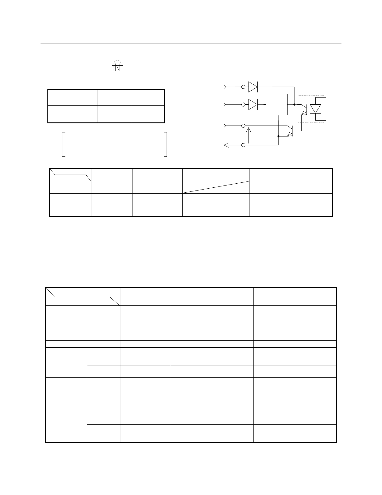
4. WIRING
4-9
Note 1) : For the parts marked , use a twisted pair shielded cable.
Note 2) : Select the power supply from the two types, 5 V or 12 V to 24 V.
CN1 -
38 pin
CN1 -
49 pin
5 V used Connected Open
12 to 24 V used Open Connected
Note 3) : RDY (RDY1 or 2 terminal) output is optional.
RDY (RDY1 or 2 terminal) is a contact output.
Contact rating: 250 VAC, 2 A
30 VDC, 2 A
Inductive load: COSφ = 0.4, L/R = 7 mS
Note 4) :
Amp. capacity
CND terminal
*1
Built-in type
regenerative resistor
Use of built-in type
regenerative resistor
*2
Method of connecting external
regenerative resistor *3
15, 30 A
(Normal)
P, Y (or COM), N None Connect it between
the P and Y (or COM) terminals.
30 A
(Special)
P, Y, N Equipped Same as default connection.
Connect it between the P and
Y terminals in the same way
as on shipment.
Connect it between
the P and Y terminals after removing
the wiring connected between the P
and Y terminals.
*4
*1 : The N terminal is for maintenance (high-voltage circuit). So, do not wire the N terminal.
*2 : The thermostat contact output of the built-in regenerative resistor is connected inside the amplifier.
*3 : A thermostat for the external regenerative resistor shall be built into the user device, or connected to the external overheat detection
input to protect the resistor.
*4 : Be careful not to bring the removed wire into contact with the conductive parts.
Note 5) : Refer to 4.6.2 CN1 & CN2 Shielding Procedure.
Note 6) : Motor connection differs to the motor specifications. The indications of red, white, black, green and orange apply when the motor
power and brake lines are the lead type. When they are the cannon plug type, connect them according to the motor specifications.
Note 7) : For how to wire the sensor connector, refer to the sensor wiring diagram.
Note 8) : The functions of command input differ depending on control modes.
Command input terminal
Control mode
Position command
pulse input
Velocity command input
Torque command input
Position control type − Velocity addition input is assumed
depending on the setting of Func1.
Torque compensation input is
assumed depending on the setting of
Func1.
Velocity control type − Velocity command input Torque compensation input is
assumed depending on the setting of
Func1.
Torque control type − − Torque command input
Velocity/torque
switch type
No switching − Velocity command input Torque compensation input is
assumed depending on the setting of
Func1.
During
switching
− − Torque command input
Position/torque
switch type
No switching Position command
pulse input
Velocity addition input is assumed
depending on the setting of Func1.
Torque compensation input is
assumed depending on the setting of
Func1.
During
switching
− − Torque command input
Position/velocity
switch type
No switching Position command
pulse input
Velocity addition input is assumed
depending on the setting of Func1.
Torque compensation input is
assumed depending on the setting of
Func1.
During
switching
− Velocity command input Torque compensation input is
assumed depending on the setting of
Func1.
5 V input
38
12 V to 24 V
input
Max.
30 VDC
O I
49
G
5 V input:
10 mA max.
12 to 24 V input:
50 mA max.
Output common
Page 59
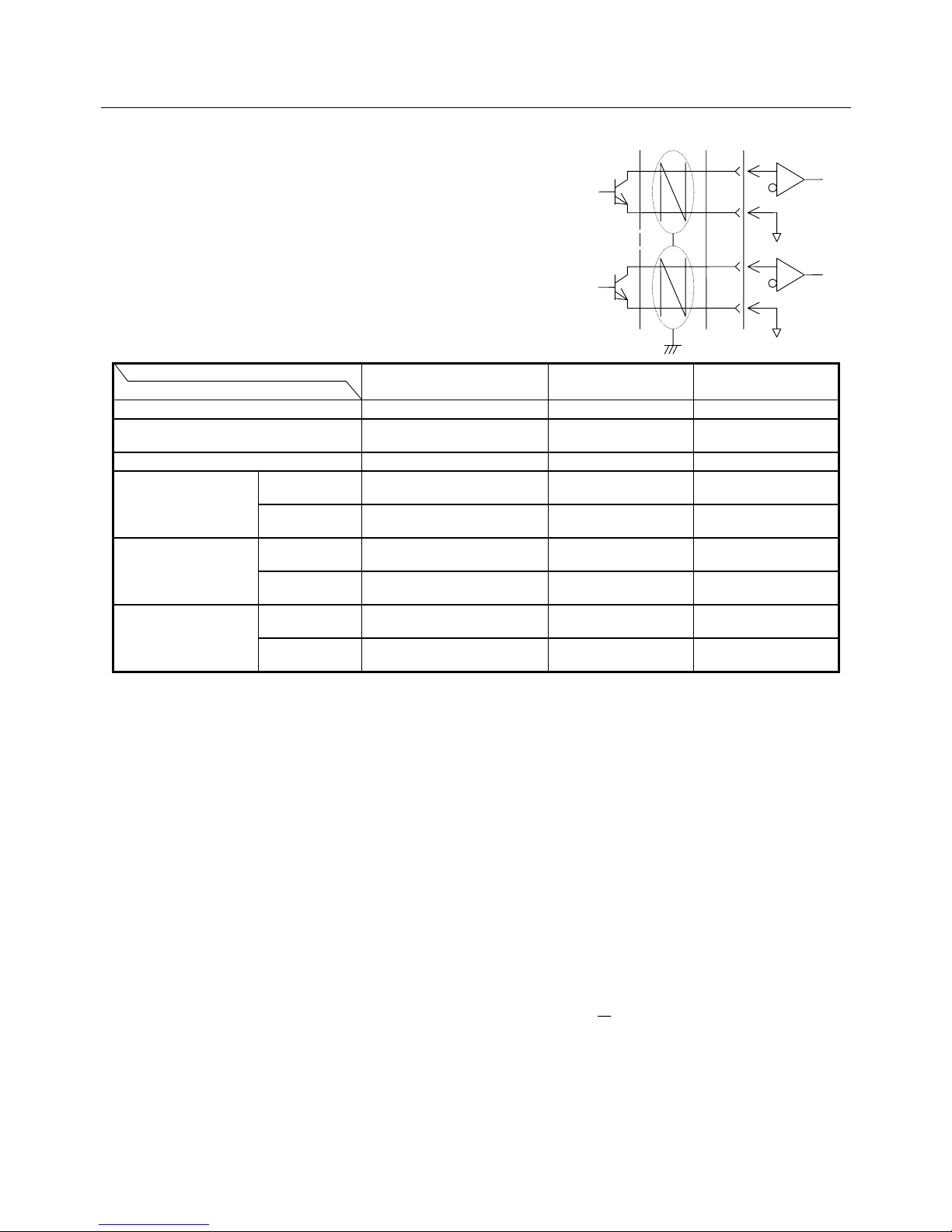
4. WIRING
4-10
For the details of the control mode and Func1 setting, refer to
the user's manual.
The polarity of command input can be reversed.
Refer to the figure on the right when connecting the position
command pulse input to the open collector output.
Note 9) : Forward/backward revolution overtravel input
By setting Func0, this function can be deleted or set
to the a-contact input.
Note 10) : The function of the general-purpose input can be
selected from the table below.
General-purpose input terminal
Control mode
34 pin 35 pin 36 pin
Position control type Deviation clear (1) (1)
Velocity control type Internal velocity command,
revolution direction input
(2) (2)
Torque control type
−
(3) (3)
Velocity/torque switch
type
No switching Internal velocity command,
revolution direction input
Control mode switching
input or (2).
Control mode switching
input or (2).
During switching
−
Control mode switching
input or (3).
Control mode switching
input or (3).
Position/torque switch
type
No switching Deviation clear Control mode switching
input or (1).
Control mode switching
input or (1).
During switching
−
Control mode switching
input or (3).
Control mode switching
input or (3).
Position/velocity switch
type
No switching Deviation clear Control mode switching
input or (1).
Control mode switching
input or (1).
During switching Internal velocity command,
revolution direction input
Control mode switching
input or (2).
Control mode switching
input or (2).
(1) : Functions can be selected among external overheating detection, proportional control, command multiplication and command pulse
inhibit.
(2) : Functions can be selected among external overheating detection, proportional control, zero clamp and internal setting velocity select.
(3) : Available as the external overheating detection input function.
In addition to the above, it can also be set as the gain switch input.
One pin can be set to have several or no functions.
For details, refer to the operation manual.
Note 11) : General-purpose output
By setting Func4, functions can be selected among current limit, low velocity, high velocity, velocity match, positioning complete and
command receive enabled. Output logic can also be selected.
Note 12) : Alarm output
Output alarm state using codes. It can also be output using bits by setting.
Note 13) : Forward/backward revolution current limit input
By changing the setting, both forward and backward revolution currents can be limited using the revolution current limit or the
backward revolution current can be limited using positive voltage. It can also be limited using the internal setting.
Note 14) : Your are required to prepare the power. Either of the inputs can be selected.
Note 15) : The R, S, T, r, t, RDY1, RDY2, P, Y (or COM), N, U, V and W terminals are high-voltage circuits and the others are low-voltage
circuits.
For the wiring-related reason, allow sufficient distance between high- and low-voltage circuits.
Note 16) : We recommend a UL-approved earth leakage breaker be used that complies with IEC or EN standard.
Note 17) : The lithium battery connector terminals (1 and 2 pins) and encoder signals PS and PS (9 and 10 pins) are available when your
encoder is the absolute type (ABS-E, ABS-RII or ABS-E.S1).
Note 18) : Be sure to install a UL-approved, 30 A fast-blown type fuse for the main circuit power supply input.
Note 19) : Make sure to connect SG (signal ground) for difference input signal (line driver of position command/ line driver of dividing output),
or wrong operation and breakage may occur.
Fig. 4-2 (b) External Wiring Diagram (100 VAC Input Type), Precautions
26
47
Forward
revolution pulse
Backward
revolution pulse
28
48
Page 60
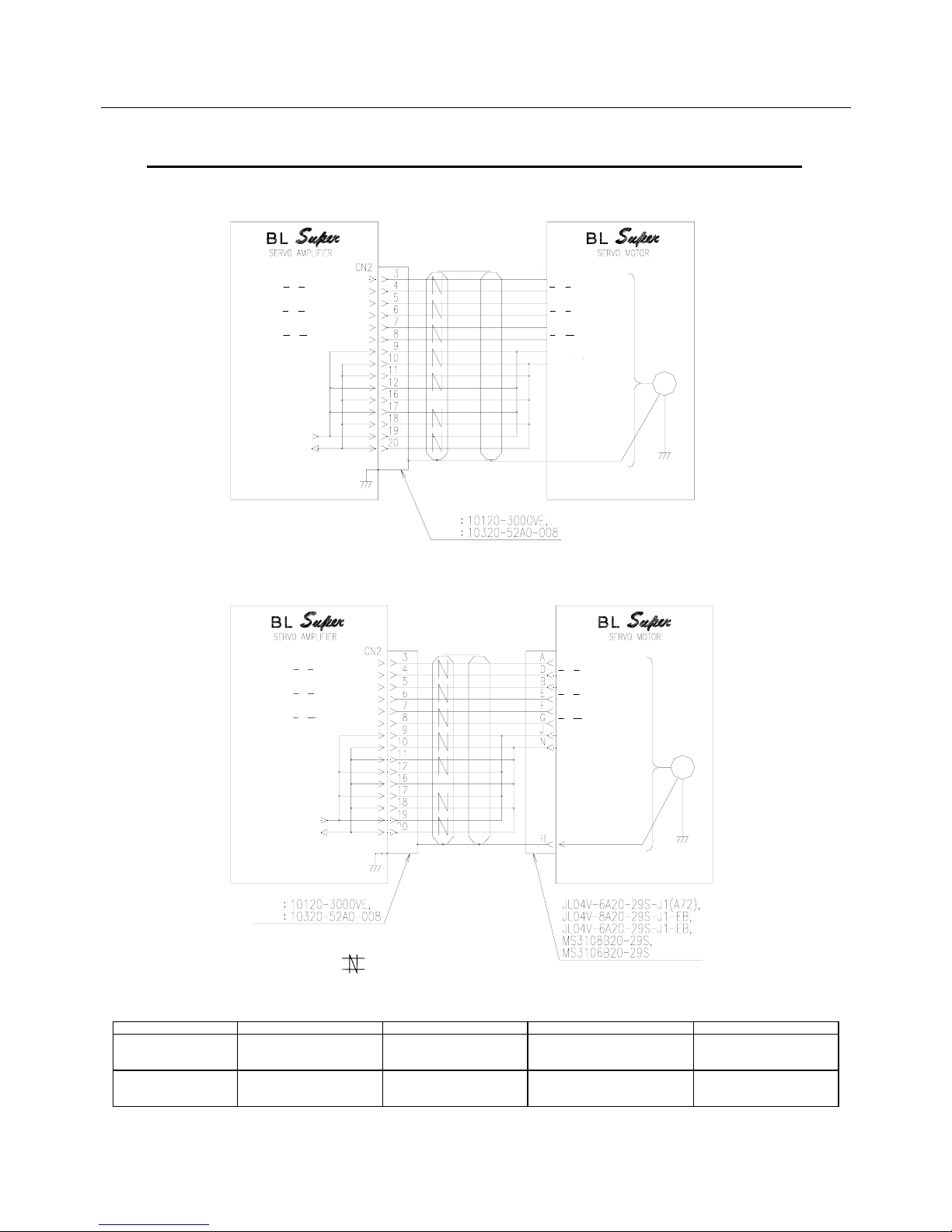
4. WIRING
4-11
Incremental encoder (INC-E): Cannon plug type
Black
Red
Yello
w
White
Violet
Green
Brown
Blue
Plug
Shell
Plug
Shell
Note
2)
Note 1)
Shield
Note 3) + 5 DCV
Note 3) GND (0 V)
Note 2)
Note 1)
Note 3) +5 VDC
Note 3) GND (0 V)
Case Earth
Incremental encoder (INC-E): Cannon plug type
Incremental encoder (INC-E): Lead wire type
A or U channel input
A or U channel input
B or V channel input
B or V channel input
C or W channel input
C or W channel input
Optical
Encoder
GND (0 V)
Sensor Incremental Encoder
+5 VDC
A or U channel output
A or U channel output
B or V channel output
B or V channel output
C or W channel output
C or W channel output
GND (0 V)
Optical
Encoder
Sensor Incremental Encoder
+5 VDC
A or U channel output
A or U channel output
B or V channel output
B or V channel output
C or W channel output
C or W channel output
A or U channel input
A or U channel input
B or V channel input
B or V channel input
C or W channel input
C or W channel input
4.3.3 Sensor Connection Diagram (INC-E Wiring-saved Incremental Encoder)
Notes: 1. For the parts marked , use a twisted pair shielded cable.
2. Refer to 4.6.2 CN1 & CN2 Shielding Procedure.
3. The sensor power connection differs depending on the cable length.
Refer to the following table.
Sensor cable length 5 m or less 10 m or less 20 m or less 30 m or less
+5 VDC wiring 19-pin connection
(9, 12 and 17 pins need not
be connected)
17- and 19-pin connection
(9 and 12 pins need not be
connected)
12-, 17- and 19-pin connection
(9 pin need not be connected)
9-, 12-, 17- and 19-pin
connection
GND (0 V) wiring 20-pin connection
(10, 11, 16 and 18 pins need
not be connected)
18- and 20-pin connection
(10, 11 and 16 pins need not
be connected)
11-, 18- and 20-pin connection
(10 and 16 pins need not be
connected)
10-, 11-, 16-, 18- and 20-pin
connection
Fig. 4-3 Sensor Connection Diagram (INC-E Wiring-saved Incremental Encoder)
Page 61
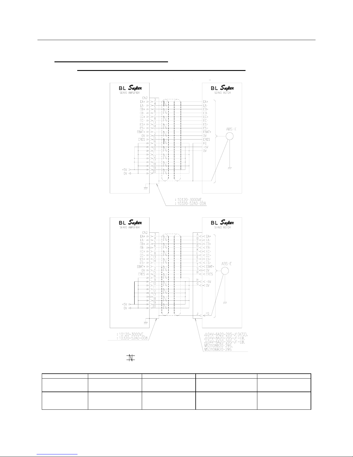
4. WIRING
4-12
4.3.4 Sensor Connection Diagram
(ABS-E Request Signal-unavailable Absolute Encoder)
Notes: 1. For the parts marked , use a twisted pair shielded cable.
2. Refer to 4.6.2 CN1 & CN2 Shielding Procedure.
3. The sensor power connection differs depending on the cable length. Refer to the following table.
Sensor cable length 5 m or less 10 m or less 15 m or less 25 m or less
+5 V wiring 19-pin connection
(9, 12 and 17 pins need not
be connected)
17- and 19-pin connection
(9 and 12 pins need not be
connected)
12-, 17- and 19-pin connection
(9 pin need not be connected)
9-, 12-, 17- and 19-pin
connection
0 V wiring 16- and 20-pin connection
(10, 11 and 18 pins need not
be connected)
16-, 18- and 20-pin
connection
(10 and 11 pins need not be
connected)
11-, 16-, 18- and 20-pin
connection
(10 pin need not be connected)
10-, 11-, 16-, 18- and 20-pin
connection
Fig. 4-4 Sensor Connection Diagram (ABS-E Absolute Encoder)
Plug
Shell
Note
2)
Note 1)
Shield
Note 3
Note 3
Sensor Absolute Encoder
Blue
White/blue
Sensor Absolute Encoder
Yello
w
White/yello
w
Orange
White/orange
Brown
White/brown
Black
Green
White/black
White/green
Red
White
/
red
Plug
Shell
Note
2)
Note 1)
Note 3
Note 3
Absolute encoder (ABS-E): Lead wire type
Absolute encoder (ABS-E): Cannon plug type
Page 62
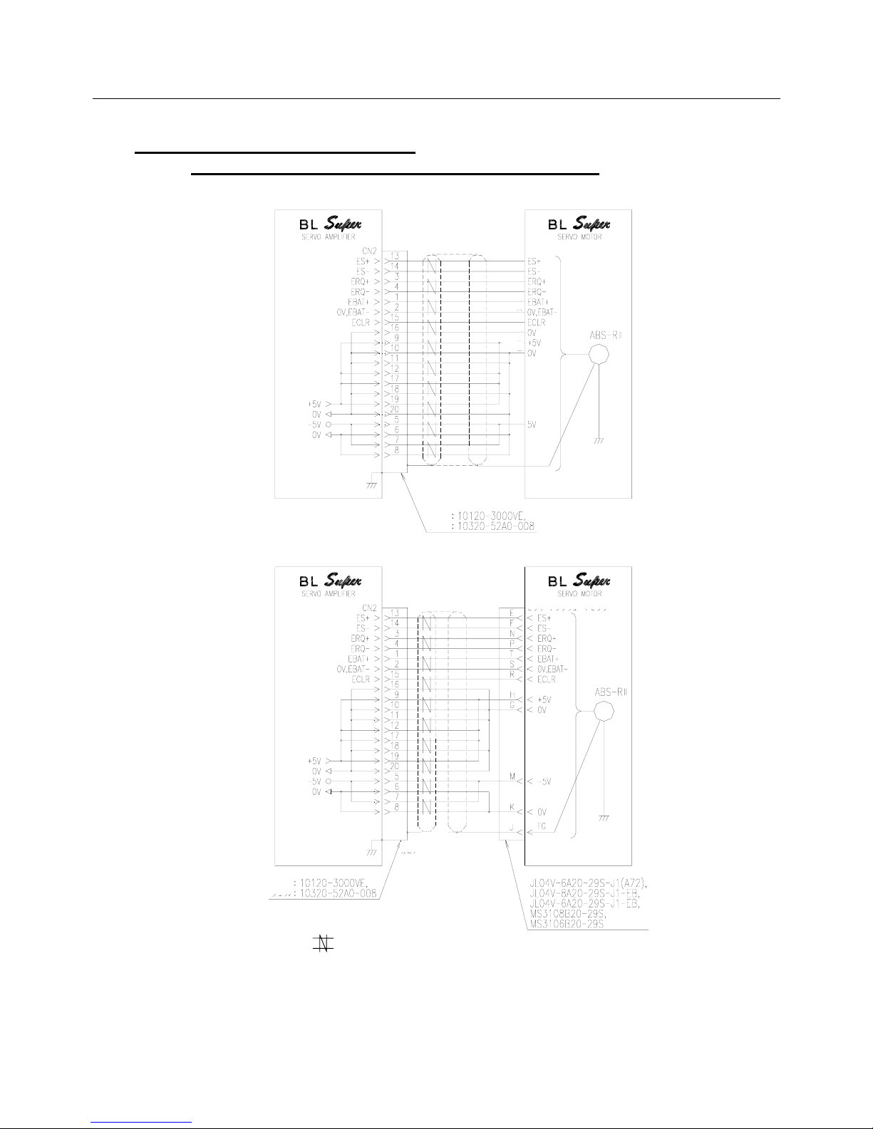
4. WIRING
4-13
4.3.5 Sensor Connection Diagram
(ABS-RII Request Signal-available Absolute Sensor)
Notes: 1. For the parts marked , use a twisted pair shielded cable.
2. Refer to 4.6.2 CN1 & CN2 Shielding Procedure.
3. When the sensor cable length is 5m or less, 11, 12, 17 and 18 pins need not be connected.
When the length is between 5 m and 30 m, connect all pins.
Fig. 4-5 Sensor Connection Diagram (ABS-RII Absolute Sensor)
Shield
Plug
Shell
Note
2)
Note 1)
Note 3
Note 3
Note 3
Blue
Brown
Sensor Absolute Encoder
Green
Orange
Pink
White
Purple
Red
Yello
w
Black
Gray
Plug
Shell
Note2)
Note 1)
Note 3
Note 3
Note 3
Sensor Absolute Encoder
A
bsolute sensor (ABS-RII): Lead wire type
Absolute sensor (ABS-RII): Cannon plug type
Page 63
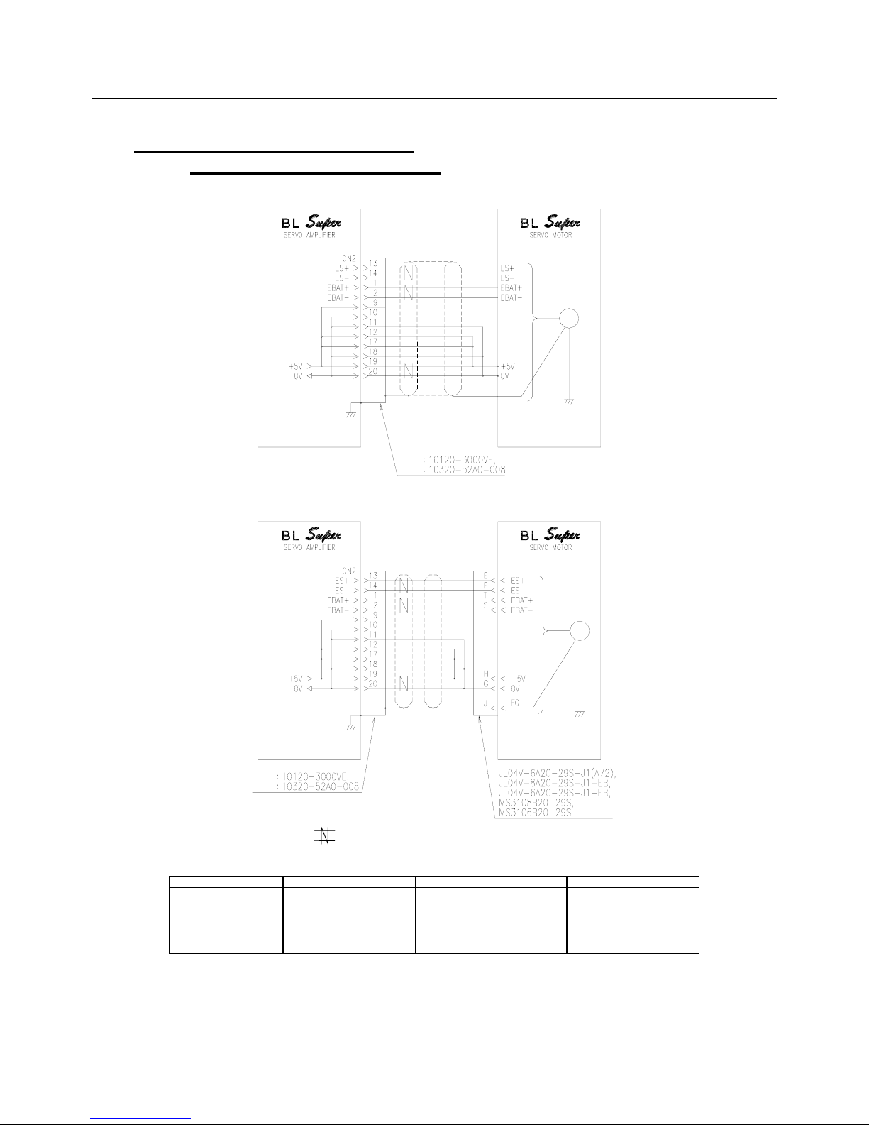
4. WIRING
4-14
4.3.6 Sensor Connection Diagram
(Wiring-saved Absolute Sensor)
Absolute sensor (E03B151302): Lead wire type
Notes: 1. For the parts marked , use a twisted pair shielded cable.
2. Refer to 4.6.2 CN1 & CN2 Shielding Procedure.
3. The sensor power connection differs depending on the cable length. Refer to the following table.
Sensor cable length 10 m or less 25 m or less 40 m or less
+5 V wiring 19-pin connection
(12 and 17 pins need not be
connected)
17- and 19-pin connection
(12 pin need not be connected)
12-, 17- and 19-pin
connection
0 V wiring 20-pin connection
(11 and 18 pins need not be
connected)
18- and 20-pin connection
(11 pin need not be connected)
11-, 18- and 20-pin
connection
4. In case of application not using multi-rotational part, wiring of “EBAT+” and “EBAT-“ are not necessary.
However, set Func6, bit5 to “1”.
Fig. 4-6 Sensor Connection Diagram (Wiring-saved Absolute Encoder ABS-E.S1)
Shield
Plug
Shell
Note 3
Note 3
Blue
Brown
Sensor Absolute Encoder
Purple
Pink
Red
Black
Absolute sensor (E03B151302): Cannon plug type
Note
2
Note 1
Plug
Shell
Note2
Note 1
Note 3
Note 3
Sensor Absolute Encoder
Page 64
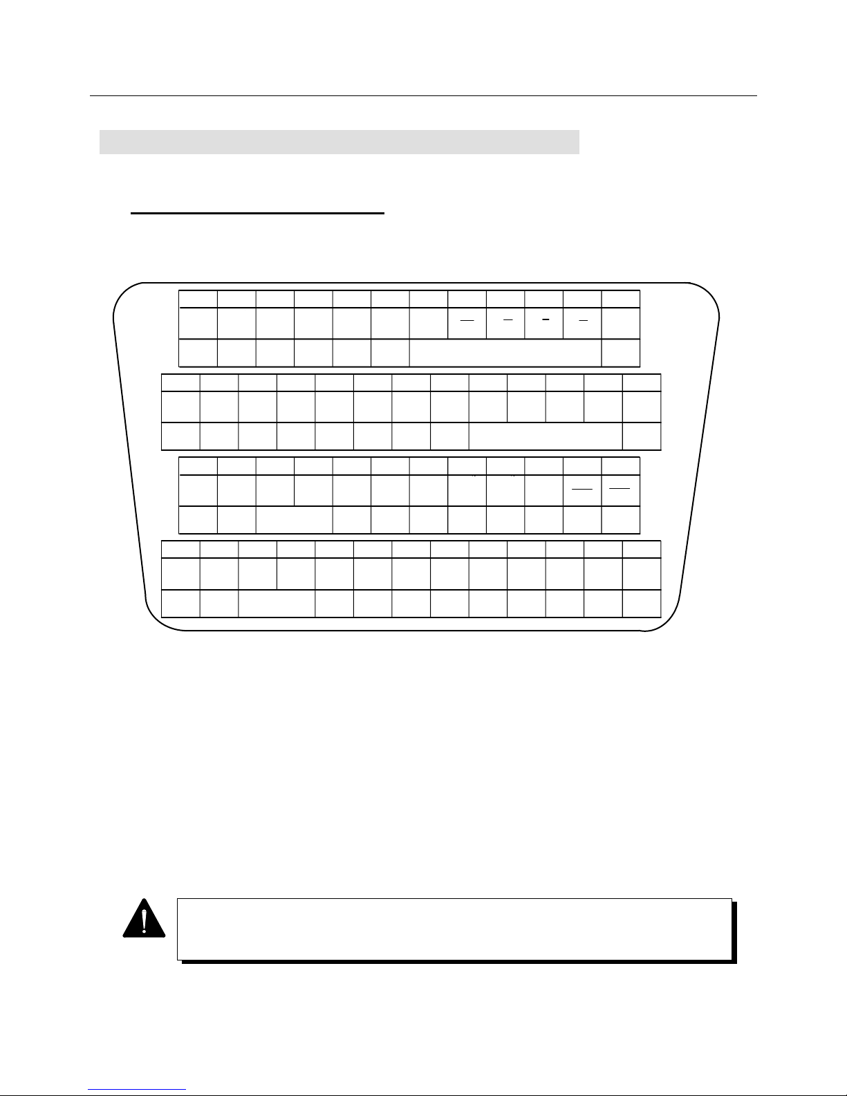
4. WIRING
4-15
4.4 Connector Terminal Arrangement Input/
Output Signal Diagram
4.4.1 CN1: Interface Connector
CN1 is an interface connector to a host computer or the like.
The connector of the amplifier is "10250-52A2JL" (made by Sumitomo 3M).
1
2
3
4
5
6
7
8
9
10
11
12
13
14
15
16
17
18
19
20
21
22
23
24
25
26
27
28
29
30
31
32
33
34
35
36
37
38
39
40
41
42
43
44
45
46
47
48
49
50
BAT-
BAT+
A
A
B
B
C
C
PS
PS
SG
SG
SG
SG
SG
MON2
MON1
COP
COPG
PIL
NIL
VCMDG
TCMD
TCMDG
/
VCMD
~24V
DC5V
~24V
COM
DC12V
~24V
COM
DC12V
PPC
PPC
NPC
NPC
ILM
RST
NROT
PROT
汎用入力
汎用入力
汎用入力
SON
汎用出力
5V
SRDY
HBON
ALM1
ALM2
ALM8
ALM4
汎用出力
DC12V
~24V
DC5V
~24V
バッテリ
マイナス側
プラス側
バッテリ
位置信号出力
位置信号出力
C相
(
オープンコレクタ
出力
)
C相
コモン
モニタ
モニタ
出力1
出力2
モニタ
コモン
正転側
逆転側
電流制限
電流制限
電流制限
コモン
速度指令
トルク指令
コモン
速度指令
トルク指令
入力シーケンス
電源1
出力シーケンス
電源コモン
出力シーケンス
電源コモン
入力シーケンス
電源2
出力シーケンス
電源
正転パルス
指令
逆転パルス
指令
正転パルス
指令
指令
逆転パルス
パルス指令
パルス指令
コモン
コモン
電流制限
許可
警報
リセット
逆転側
正転側
オーバー
トラベル
オーバー
トラベル
汎用入力
汎用入力
汎用入力
汎用出力
汎用出力
サーボオン
運転準備
完了
出力シーケンス
電源
保持ブレーキ
タイミング出力
警報出力
警報出力
注1
注1
注1
注1
注2
注2
注2
注2
注2
注2
注2
注3
注3
注5
注5
注6
注6
注6
注6
注8
注8
注7
注7
注7
注4
注4
注3
注9
注6
Fig. 4-7 CN1 Connector Terminal Arrangement Diagram
Notes :
1. Battery connector terminal and position signal output PS terminal:
Available when being used together with the absolute encoder (ABS-E) or the absolute sensor
(ABS-RII).
2. Command input : Functions differ depending on the control modes.
3. Current limit : The input method can optionally be set.
4. Overtravel : The input method can optionally be set.
5. Monitor output : The signal and output range to be monitored can be selected.
6. Alarm output : The output method and polarity can be selected.
7. General-purpose input : Selectable from multiple signals. The contents of signals differ depending
on the control modes.
8. General-purpose output : Multiple signals can be selected.
9. Holding brake timing output : Timing output for operating the motor holding brake.
The timing can be adjusted according to the machine.
The above figure shows the arrangement when viewed from the wiring section of the
connector. Connector at cable side is not attached to Servo Amplifier, and should be
prepared by user.
12VDC
to 24V
Note2
Note2 Note3 Note5
Note5
Note2 Note3
Note1 Note1
Note1 Note1
Note2 Note2 Note3Note4Note7Note8Note6 Note6
Note6 Note6 Note8Note9 Note7 Note7
Note4
Note6
Note2 Note2
Output
sequence
power
common
Torque
command
Velocity/
torque
command
Forward
revolution
side current
limit
Monitor
output 2
Monitor
common
Position signal output
Battery
negative
side
12VDC
to 24V
5VDC
to 24V
Output
sequence
power
common
Input
sequence
power 1
Velocity
command
Backward
revolution
side current
limit
Current
limit
common
Monitor
output 1
C-phase
common
C-phase
(open
collector
output)
Position signal output
Battery
positive
side
12VDC
to 24V
Output
sequence
power
Pulse
command
common
Alarm output
Operation
ready
complete
General-
purpose
output
General-
purpose
output
General-
purpose
input
General-
purpose
input
Backward
revolution
side
over travel
Current
limit
permit
Backward
revolution
pulse
command
Forward
revolution
pulse
command
Forward
revolution
pulse
command
Backward
revolution
pulse
command
Forward
revolution
pulse
command
Servo
ON
Alarm
reset
Alarm output
Pulse
command
common
12VDC
to 24V
Input
sequence
power 2
General-
purpose
output
Output
sequence
power
General-
purpose
input
Generalpurpose
input
General-
purpose
input
General-
purpose
input
General-
purpose
output
Holding
brake
timing
output
Page 65
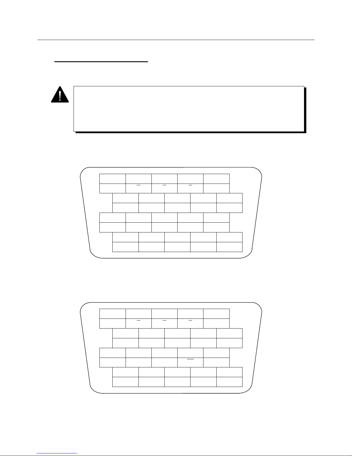
4. WIRING
4-16
4.4.2 CN2 Sensor Connector
The amplifier-side connector is "10220-52A2JL" (made by Sumitomo 3M).
● Incremental encoder (INC-E) terminal arrangement diagram
Fig. 4-8 CN2 Connector (INC-E Incremental Encoder) Terminal Arrangement Diagram
● Request signal-unavailable absolute encoder (ABS-E) terminal arrangement diagram
Fig. 4-9 CN2 Connector (ABS-E Request Signal-unavailable Absolute Encoder)
Terminal Arrangement Diagram
2 4
A
6
B C
8
SG
10
1 3
A
5
B C
7
SG
9
5 V
12 14 16
SG SG
18
SG
20
SG
11 13 15
5 V
17
5 V
19
BAT−
PS
ECLR PS
BAT+
Reserved
2 4
A
6
B C
8
SG
10
Reserved
1 3
A
5
B C
7
5 V
9
5 V
12 14
Reserved
16
SG SG
18
SG
20
SG
11 13 15
5 V
17
5 V
19
ReservedReserved
• Connection differs depending on the type of the Servomotor sensor to be combined with
the Servo Amplifier.
• Note that the hardware inside the Servo Amplifier differs between the incremental
encoder (INC-E) or the request signal-unavailable absolute encoder (ABS-E) and the
request signal-available absolute sensor (ABS-RII) or wiring-saved absolute sensor
(ABS-E.S1).
Page 66
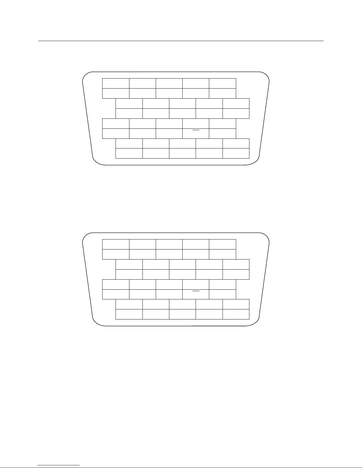
4. WIRING
4-17
● Request signal-available absolute sensor (ABS-RII) terminal arrangement diagram
Fig. 4-10 CN2 Connector (ABS-RII Request Signal-available Absolute Sensor)
Terminal Arrangement Diagram
● Wiring-saved absolute sensor (ABS-E.S1) terminal arrangement diagram
Fig. 4-11 CN2 Connector (ABS-E.S1 Wiring-saved Absolute Sensor)
Terminal Arrangement Diagram
2 4
REQ−
6
SG SG
8
SG
10
1 3
REQ+
5
−5 V −5 V
7
5 V
9
5 V
12 14 16
SG SG
18
SG
20
SG
11 13 15
5 V
17
5 V
19
BAT−
PS
ECLR PS
BAT+
2 4
OPEN
6
OPEN OPEN
8
SG
10
1 3
OPEN
5
OPEN OPEN
7
5 V
9
5 V
12 14 16
SG SG
18
SG
20
SG
11 13 15
5 V
17
5 V
19
BAT−
ES
OPEN ES
BAT+
Page 67
4. WIRING
4-18
4.5 Wiring Procedure
The Servo Amplifier is control unit to process signals of several mV or less.
Therefore, perform wiring observing the following items.
1 Input/output or sensor signal line
For the input/output or sensor signal line, use recommended cables or their equivalent
(twisted wires or multi-conductor twisted lump shielded wires). Wire them by taking the
following precautions into account.
• Wire them in the shortest distance.
• Separate the main circuit line from the signal circuit line.
• Do not wire the main circuit line on the side of the amplifier or near another amplifier.
• We recommend to use an "insulation sleeve-equipped bar terminal" if a certain
insulation distance is required to be secured between main circuit wires or between
main and signal circuit wires.
(This terminal cannot be used when AWG12 wire is used.)
2 Earth cable
• Earth the wire with the diameter of 2.0 mm
2
at one point.
• Perform class 3 earth (earth resistance value: 100 Ω max.).
• Be sure to connect the frame of the Servomotor (the grounding wire and the terminal)
to the PE (protective earth) terminal ( ) of the Servo Amplifier.
• Be sure to connect the PE (protective earth) terminal ( ) for the Servo Amplifier to
that for the control panel. Be sure to ground it at one point.
3 Measures against malfunction due to noise
Note the following to prevent malfunction due to noise.
• Arrange the noise filter, the Servo Amplifier, and the upper controller as near as
possible.
• Be sure to install a surge absorbing circuit on the coils for the relay, the magnetic
contactor, the induction motor and the brake solenoid.
• Don’t pass main circuit signal lines in the same duct or overlap them.
• When a large noise source such as an electric welding machine or an electric
discharge machine exists nearby, insert a noise filter into the power supply and the
input circuit.
• Don't bind the noise filter primary and secondary side wires together.
• Don't make the earth cable longer.
4 Measure against radio interference
Since the Servo Amplifier is an industrial equipment, no measure against radio
interference has been taken to it. If the interference causes some problem, insert a line
filter to the power line input.
Page 68
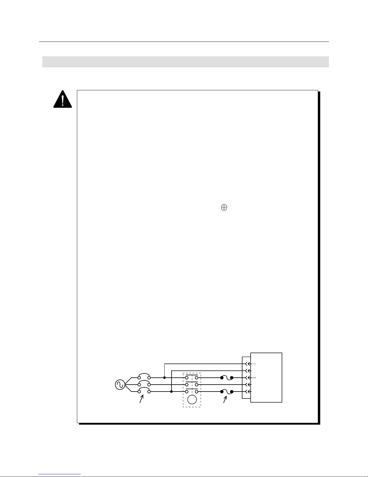
4. WIRING
4-19
1 Noise processing
The main circuit of the Servo Amplifier uses IGBTs under PWM control. If the wiring
processing is not earthed properly, switching noise may occur by di/dt and dv/dt
generated when IGBT is switched. Because the Servo Amplifier incorporates
electronic circuits such as the CPU, it is necessary to perform wiring and processing so
as to prevent external noise from invading to the utmost.
To prevent trouble due to this noise in advance, perform wiring and grounding securely.
The power noise resistance (normal, common noise) of the Servo Amplifier is within 30
minutes at 1500 V, 1 µsec. Do not conduct a noise test for more than 30 minutes.
2 Motor frame earth
When the machine is grounded through the frame, Cf x dv / dt current flows from the
PWM power unit of the Servo Amplifier through the motor floating capacity (Cf).
To prevent any adverse effect due to this current, be sure to connect the motor terminal
(motor frame) to the PE (protective earth) terminal ( ) of the Servo Amplifier.
Also, be sure to ground it directly.
3 Wire grounding
When a motor is wired to a metal conduit or box, be sure to ground the metal. In this
case, perform one-point grounding.
4 Miswiring
Since miswiring in the Servo Amplifier and the Servomotor may damage equipment, be
sure to check that wiring has been performed properly.
5 Protection against input overcurrent
Be sure to connect a UL-approved circuit breaker and a fast-blown fuse to the Servo
Amplifier input to protect the power line. For the capacity of the fast-blown fuse, refer
to the following.
Amplifier capacity 15 A, 30 A : 30 A fast-blown type
Amplifier capacity 50 A : 50 A fast-blown type
r
t
R
S
T
速断タ イ プ ヒ ュ ーズ
MC
AC電源
サーキッ ト ブ レ ーカ
サーボア ン プP Y 2
CNA
4.6 Precautions on Wiring
Perform wiring observing the following completely.
PY2
Servo Amplifier
CN
A
AC power
supply
Fast-blown fuse
Circuit breaker
r
t
R
S
T
MC
Page 69
4. WIRING
4-20
6 Leakage current
Even after the motor frame is grounded as specified, leakage current flows in the input
power line. When selecting a leak detection-type breaker, make sure that no
oversensitive operation is caused by high-frequency leakage current by referring to
“Servo Amplifier/Servomotor Leakage Current” in the specifications.
7 Power supply surge
When a surge voltage occurs in the power supply, connect a surge absorber between
the powers to absorb the voltage before operation.
8 Lightning surge
When there is a possibility that a lightning surge over 2kV may be applied to the Servo
Amplifier, take countermeasures against the surge at the control panel inlet.
For lightning surge protectors to be inserted to each Servo Amplifier inlet, the product in
the following table or its equivalent is recommended.
Page 70
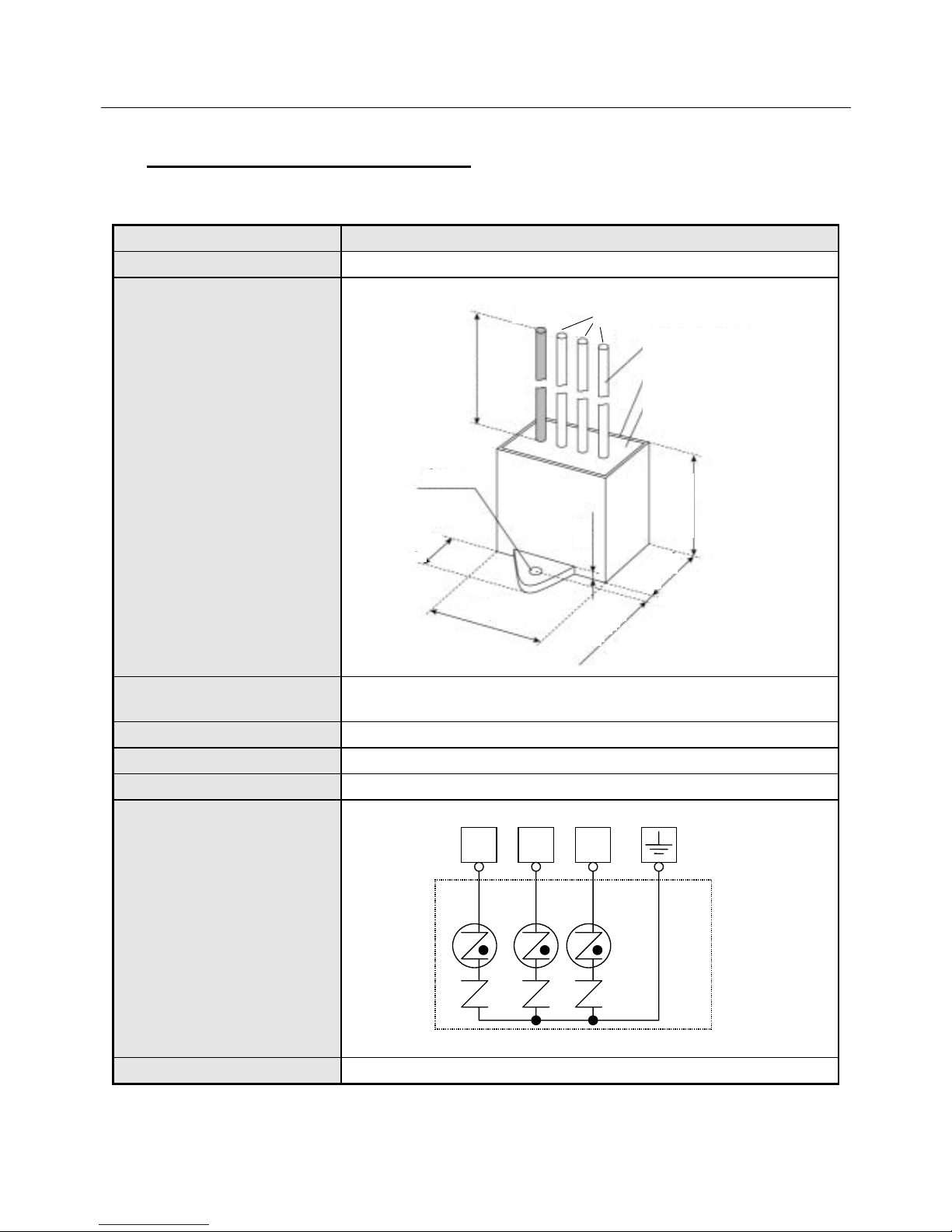
4. WIRING
4-21
4.6.1 Recommended Surge Protector
When purchasing the following, directly make a reference to the maker for it.
Item Specification
Model No. R.A.V-781BXZ-2A (Okaya Electric Industries Co., Ltd.)
External dimensions
Maximum allowable circuit
voltage
300 Vrms
Clamp voltage 783 V±10%
Surge-resistant current 2500 A (waveform) 8 × 20 µs
Surge-resistant voltage 20 kV (waveform) 1.2 × 50 µs
Connection diagram
Weight Approx. 100 g
Fig. 4-12 Recommended Surge Protector
321
Yellow/green
BlackBlackBlack
Yellow/green
11±1
28.5±1
200
28.5±1
4.5
φ
4.2
Resin : Expoxy, black
Case : PBT, black
UL-1015AWG16 (0.26.26)
black, yellow/green
Black
+30
−0
5.5±1
44.5±1
Page 71
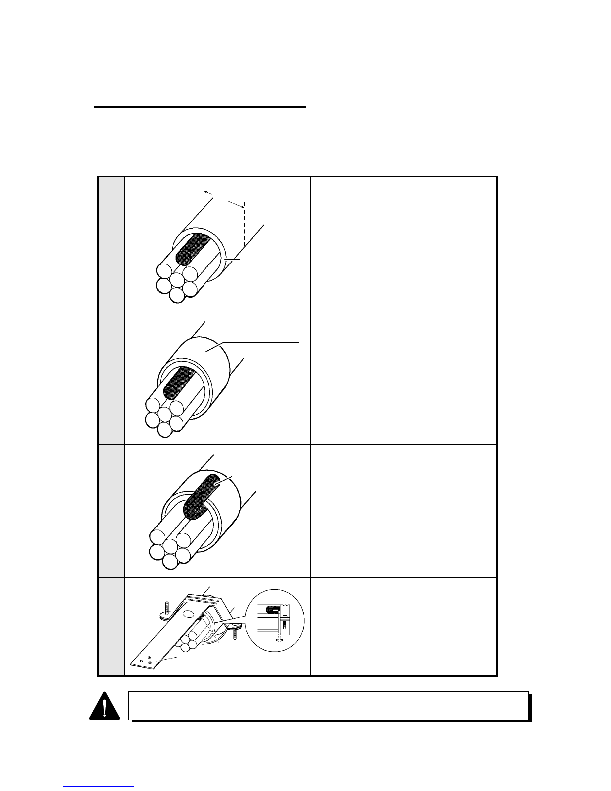
4. WIRING
4-22
4.6.2 CN1 & CN2 Shielding Procedure
The following figure shows the connector shielding procedure for the CN1 or CN2 connector.
There are two shielding procedures, clamp and soldering processing.
● Clamp processing
1
Remove the cable sheath.
2
Mount a tape or a compression insert.
At this time, the tape or the compression
insert should be completely on the cable
sheath.
3
Fold back the drain wire.
4
Tighten the cable clamp from on the drain
wire.
Set it about 1 mm away from the end face
of the tape or the compression insert.
Set the compression insert before soldering the cable to the connector.
Tape or
compression insert
Drain wire
Sheath
φ
A
Ground plate
Drain wire
1 mm
Page 72
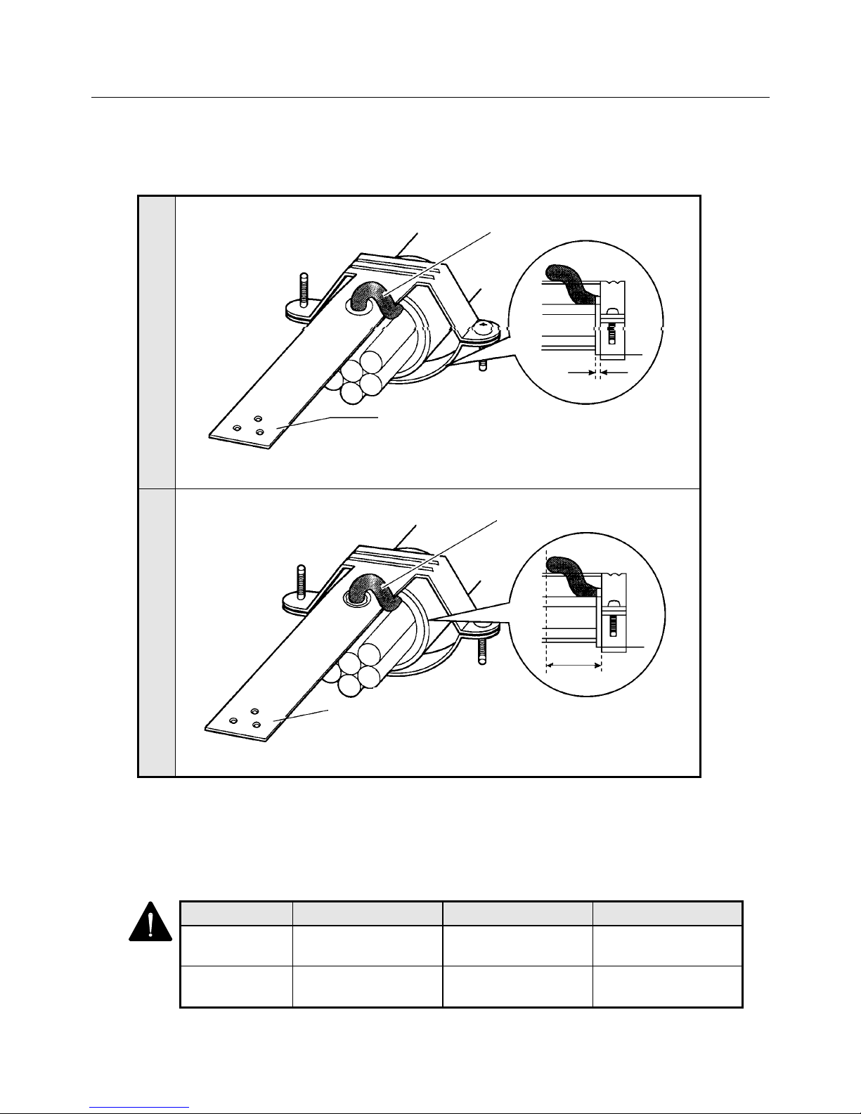
4. WIRING
4-23
● Soldering processing
Procedures 1 and 2 are the same as the clamp processing.
1
Turn the cable and bring the drain wire near the ground plate.
2
● Applicable CN2 φ A Size
The applicable CN1 and CN2 φA sizes are shown in the following table.
Table 4-3 Applicable CN2 φ A Size
1 mm
Ground plate
Drain wire
Ground plale
5 mm
Solder the drain wire
(where ○ is narked.)
Connector No. Applicable φA size Connector model name Maker name
CN1 15.0 to 16.5 mm 10150-3000VE
10350-52A0-008
Sumitomo 3M Ltd.
CN2 10.5 to 12.0 mm 10120-3000VE
10320-52A0-008
Sumitomo 3M Ltd.
Page 73
4. WIRING
4-24
4.6.3 Typical CN2 Compression Insert Application
The following products are recommended as a CN2 compression insert.
Table 4-4 CN2 Compression Inserts
Compression insert No. Applicable cable outer
diameter (φA)
Maker name
10607-C058
10607-C068
10607-C078
10607-C088
10607-C098
φ4.0 to 5.0 mm
φ5.0 to 6.0 mm
φ6.0 to 7.0 mm
φ7.0 to 8.0 mm
φ8.0 to 9.0 mm
Sumitomo 3M Ltd.
1 The above products are applicable to the connector CN2.
2 When purchasing the above products, directly make a reference to the maker for them
or ask our company for information.
For inquiry: Sumitomo 3M Ltd., Tokyo Branch
Phone: +81(3)5716-7290
Page 74

5. INSTALLATION
5 - 1
INSTALLATION
5.1 Servo Amplifier Installation .......................................................... 5-2
5.1.1 Installation Place ............................................................... 5-2
5.1.2 Installation Procedure ....................................................... 5-3
5.2 Servomotor Installation ................................................................ 5-4
5.2.1 Installation Place ............................................................... 5-4
5.2.2 Installation Procedure ....................................................... 5-4
5.3 Cable Installation ......................................................................... 5-9
Page 75
5. INSTALLATION
5 - 2
5.1 Servo Amplifier Installation
Refer to the following for the Servo Amplifier installation place and procedure.
5.1.1 Installation Place
Install the Servo Amplifier by referring to the following.
Case Precautions
When installing
the Servo
Amplifier in a box
The temperature in the box may be higher than the outside temperature depending
on the power loss of built-in equipment and the dimensions of the box.
Be sure to keep the temperature around the Servo Amplifier at 55℃ or lower by
properly determining the dimensions of the box, the cooling system and the
arrangement.
For a longer lifetime and higher reliability, operate the Servo Amplifier at an in-box
temperature of lower than 40°C.
When there is a
vibration source
nearby
Install the Servo Amplifier at the base through a shock absorber so that vibration
may not be transmitted directly to the Servo Amplifier.
When there is a
heat generating
source nearby
Even it there is a possibility that a temperature rise may be caused by convection or
radiation, keep the temperature near the Servo Amplifier lower than 55°C.
When there is
corrosive gas
If the Servo Amplifier is operated for a long time, contact failure will come to occur at
contact parts (e.g., connectors). So, never install the Servo Amplifier in corrosive
gas atmosphere.
When there is
explosive gas or
combustible gas
Never install the Servo Amplifier in explosive gas or combustible gas atmosphere.
Relays and contactors, which generate arcs (sparks) inside boxes, and such parts
as regenerative brake resistor may become ignition sources, causing fires and
explosion.
When there is
dust or oil mist
Never install the Servo Amplifier in such atmosphere containing dusts or oil mists.
Dusts or oil mists adhered to or accumulated on the Servo Amplifier may lower
insulation or cause leak between conductors of applicable parts, damaging the
Servo Amplifier.
When there is a
large noise
source
Induction noise will enter input signals and the power supply circuit, causing Servo
Amplifier’s malfunction.
When there is a possibility of noise entering, take proper measures such as inserting
a noise filter, revising line wiring and preventing noise generation.
Page 76
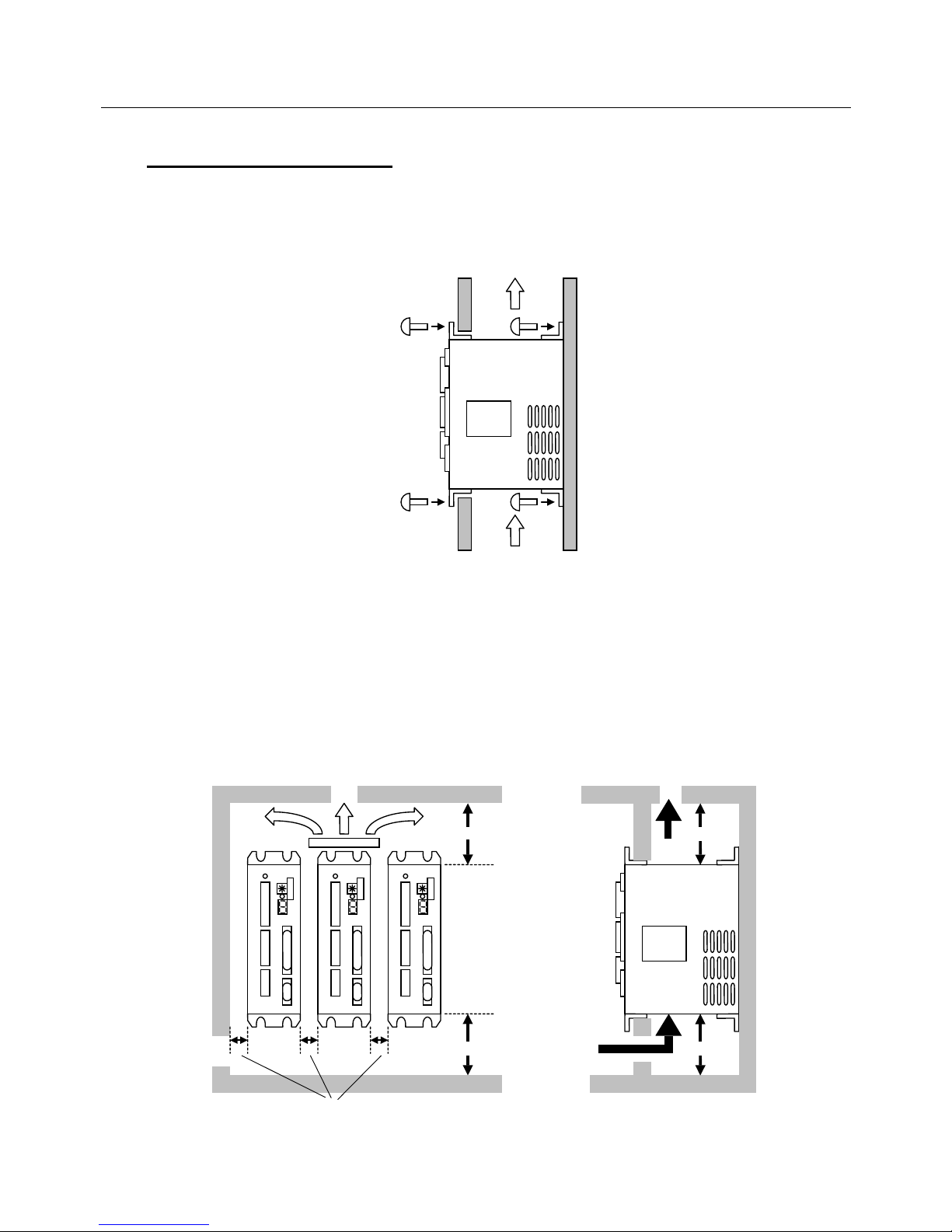
5. INSTALLATION
5 - 3
5.1.2 Installation Procedure
● Direction and Position of Installation
Install the Servo Amplifier vertically and fix the amplifier by tightening M5 screws onto the four mounting
holes as in the figure below.
Fig. 5-1
● Board arrangement conditions
• Provide a space of 50 mm at minimum on both upper and lower sides of the Servo Amplifier so as
not to prevent air from flowing out of the radiator or the amplifier. If heat remains on the upper part
of the amplifier, install a fan to force air to flow.
• Provide a space of 10 mm at minimum on both sides of the amplifier so as not to prevent radiation
from the heat sink on the side of the amplifier or air from flowing out of it.
Fig. 5-2
M5 M5
M5 M5
Servo Amp.
Rear installation
Front installation
Side view
Servo Amplifier
Draft
50 mm min.
50 mm min.
Front view
Servo Amplifier
50 mm min.
Fan
10 mm min.
50 mm min.
Page 77
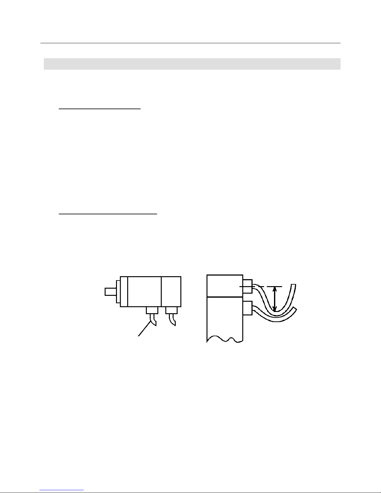
5. INSTALLATION
5 - 4
5.2 Servomotor Installation
The Servomotor is designed to be installed indoors.
Note the following precautions on the position and method for installation.
5.2.1 Installation Place
Install the Servomotor at an indoor site by referring to the following.
• Ambient temperature : 0 to 40°C
• Storage temperature : − 20 to 65°C
• Ambient humidity : 20 to 90%
• Well-ventilated places without corrosive or explosive gas
• Places free from dust or foreign materials
• Places easy to check and clean
• Always keep the oil seal lip away from oil or the Servomotor away from a large amount of water, oil or
cut liquid. The Servomotor can be protected from slight splashes by means taken on it.
5.2.2 Installation Procedure
● Direction of installation
• The Servomotor can be installed horizontally or on/under the end of a shaft.
• Set the cable from the motor with its end downward.
• At vertical installation, provide a cable trap to prevent oily water from going to the motor.
Fig. 5-4
Lead wire
Cable trap
Page 78
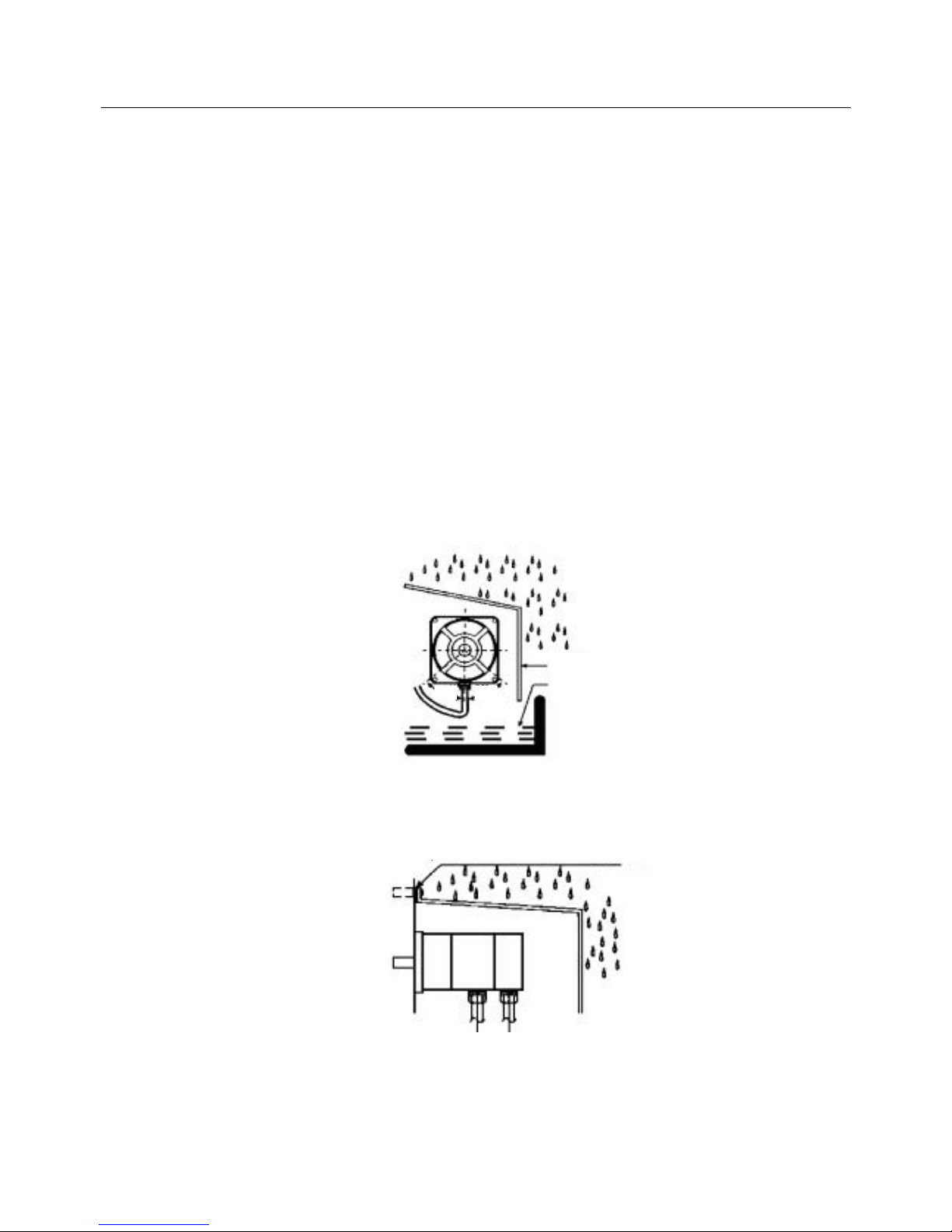
5. INSTALLATION
5 - 5
● Prevention against wetting
The motor, as a single unit, satisfies the IEC standard. Since the standard, however, is intended to
check performance over a short period of time, the following measures against wetting are required for
actual usage. Handle the system carefully, or the connector sheathes may be hit or damaged,
deteriorating waterproof function.
The cannon plug type P1, P2 and P6 as well as the P8 series motor become equivalent to IP67 by using
a waterproof connector or conduit on the other side of the cannon connector.
The P3 series motors and the P5 series motors with the flange size of 30 mm and 40 mm sqs. have
waterproofing equivalent to IP40 and the P5 series motors with the flange size of 50 mm, 70 mm and 80
mm sqs. to IP55.
• Set the connector (lead outlet) with its end downward in the angle range shown in the following
figure.
• Install the cover on the side to which water (oil) will splash.
• Install the cover with a gradient so that water (oil) may not stay.
• Avoid dipping the cable in water (oil).
• Slacken the cable outside the cover so that water (oil) may not invade the motor side.
Fig. 5-5
Fig. 5-6
50°50°
Cover
Water (oil) pool
Seal this portion with
a sheet packing.
Page 79
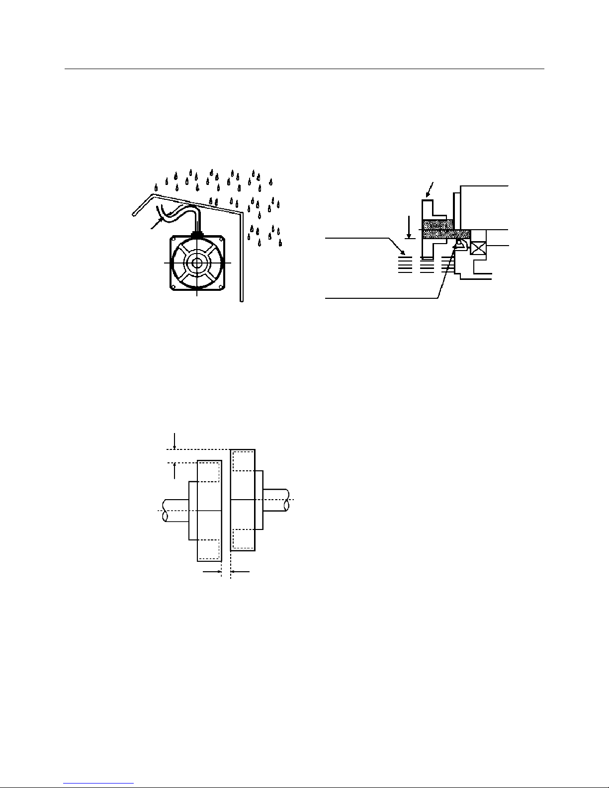
5. INSTALLATION
5 - 6
• When the connector (lead outlet) cannot be installed with its end downward by any means, slacken
the cable so that water (oil) may not invade it.
• Make the oil level of the gear box lower than the oil seal lip.
• Provide a vent to prevent the internal pressure of the gear box from rising.
Fig. 5-7
● Connection to the opposite machine
• Perform centering accurately between the motor shaft and the opposite machine as in Fig. 5-8.
Note that when a rigid coupling is used, especially, a slight offset will lead to damage of the output
shaft.
Fig. 5-8 Centering
External
diameter of
the shaft
Oil seal lip
Gear
Oil level
Motor
Slackness
The difference between the maximum and
minimum after measuring four points on the
entire circumference is 3/100 mm or less
(when rotated together with the coupling).
Page 80
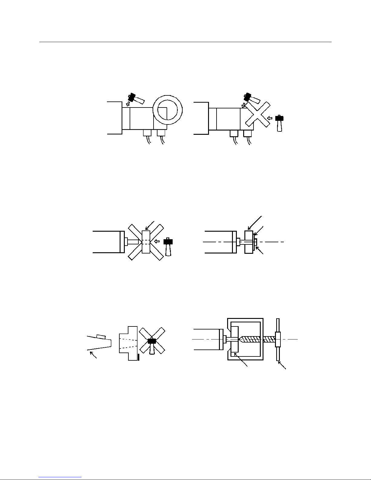
5. INSTALLATION
5 - 7
• Since a precision encoder is directly connected to the motor shaft, be careful not to give shocks to it.
If tapping on the motor is unavoidable for position adjustment or other reasons, tap on the front
flange, if possible, with a rubber or plastic hammer.
• When installing the motor to the machine, make a installing hole precisely so that the motor joint can
be smoothly connected. Also, make the installing surface as flat as possible, or the shaft or the
bearing may be damaged.
• When installing the gear, the pulley, the coupling, etc., avoid giving shocks to them by using the
screw on the shaft edge.
• Since torque is transferred, in the case of the tapered motor shaft, from the tapered surface, take
care that the key can be engaged without being tapped. Also, make a hole so that at least 70% of
the tapered surface is to be engaged.
• When removing the gear, the pulley, etc., use a dedicated extracting tool.
• When performing belt driving, check that the shaft-converted value of the belt tension does not
exceed the allowable value shown in Table 5-1.
● Allowable load of bearing
Fig. 5-1 shows the load which the Servomotor can endure.
Do not apply an excessive thrust or radial load.
The thrust or radial load in the table indicates the value when it is independently applied to the shaft.
Bolt
Plate
Pulley
Pulley
Extracting
tool
Taper
Taper
Page 81
5. INSTALLATION
5 - 8
Table 5-1 P Series Motor Allowable Radial and Thrust Load
During assembly During operation
Models Radial load
(kg)
Thrust load
(kg)
Radial load
(kg)
Thrust load
(kg)
FR F
Direction
F1
Direction
FR F
Direction
F1
Direction
P1 P10B10030 60 80 80 40 10 10
P10B10075 60 80 80 40 10 10
P10B13050 100 140 140 50 10 10
P10B13100 100 140 140 50 10 10
P10B13150 100 140 140 70 10 10
P10B18200 230 190 190 150 50 50
P2 P20B10100 100 30 30 70 30 30
P20B10150 100 30 30 70 30 30
P20B10200 100 30 30 70 30 30
P3 P30B04003 10 8 8 5 3 3
P30B04005 15 10 10 10 3 3
P30B04010 15 10 10 10 3 3
P30B06020 40 20 20 20 8 8
P30B06040 40 20 20 25 10 10
P30B08075 60 40 40 35 20 20
P5 P50B03003 7 7 7 6 2 2
P50B04006 15 10 10 10 3 3
P50B04010 15 10 10 10 3 3
P50B05005 20 20 15 15 8 8
P50B05010 20 20 15 15 8 8
B50B05020 25 20 15 15 8 8
P50B07020 25 50 20 20 10 10
P50B07030 25 50 20 20 10 10
P50B07040 25 50 20 25 10 10
P50B08040 60 80 30 35 20 20
P50B08050 60 80 30 35 20 20
P50B08075 60 80 30 35 20 20
P50B08100 60 80 30 35 20 20
P6 P60B13050 65 130 130 35 35 35
P60B13100 100 140 140 65 50 50
P60B13150 170 190 190 65 50 50
P8 P80B15075 100 140 140 65 50 50
P80B18120 150 140 140 95 50 50
Page 82
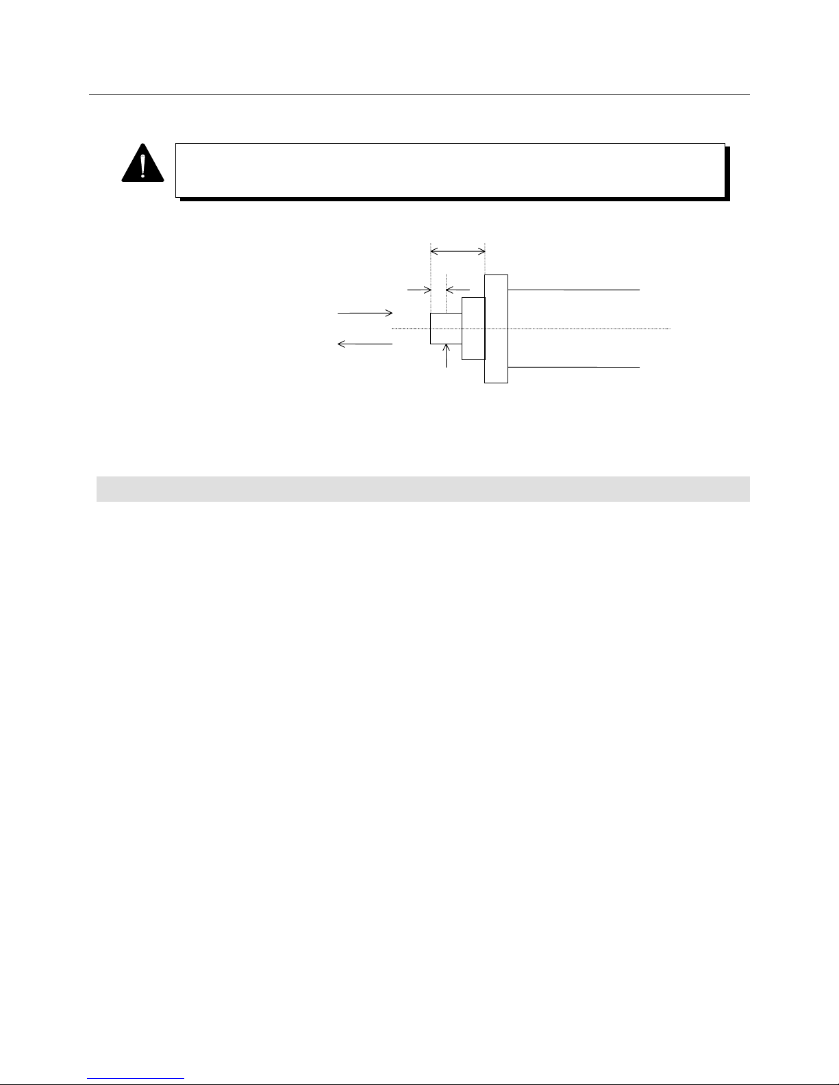
5. INSTALLATION
5 - 9
LR
LR/3
Thrust load
F direction
F1 direction
Point
loaded
Fig. 5-9 Radially loaded position
5.3 Cable Installation
• Be careful not to give stress or damage to cables.
• When the motor and cables are moved by cable bearer, determine a bending radius of each cable by
the necessary flexure lifetime and type of wire. It is recommended that the cable of a movable portion
should have a structure that permits periodic replacement. When you desire to use a recommended
cable for a movable portion, consult with our company.
The allowable radial load refers to the maximum load applicable to the point one-third of the
output shaft length away from the output shaft (see the figure below).
Page 83

6. OPERATION
6-1
OPERATION
6.1 Operation Sequence .................................................................... 6-2
6.1.1 Power ON Sequence ........................................................ 6-2
6.1.2 Stop Sequence.................................................................. 6-3
6.1.3 Servo OFF Sequence ....................................................... 6-5
6.1.4 Alarm Reset Sequence ..................................................... 6-6
6.1.5 Overtravel Sequence ........................................................ 6-7
6.2 Display ......................................................................................... 6-8
6.2.1 Status Display ................................................................... 6-8
6.2.2 Alarm Display .................................................................... 6-8
6.3 Be Sure to Check the Functioning at First ................................... 6-9
6.3.1 Minimum Wiring ................................................................ 6-9
6.3.2 Jog Operation.................................................................... 6-10
6.3.3 Reseting and Turning the Power Off ................................. 6-12
6.4 Encoder Clear Using Remote Operator
(When Absolute Encoder is Used)............................................... 6-13
Page 84
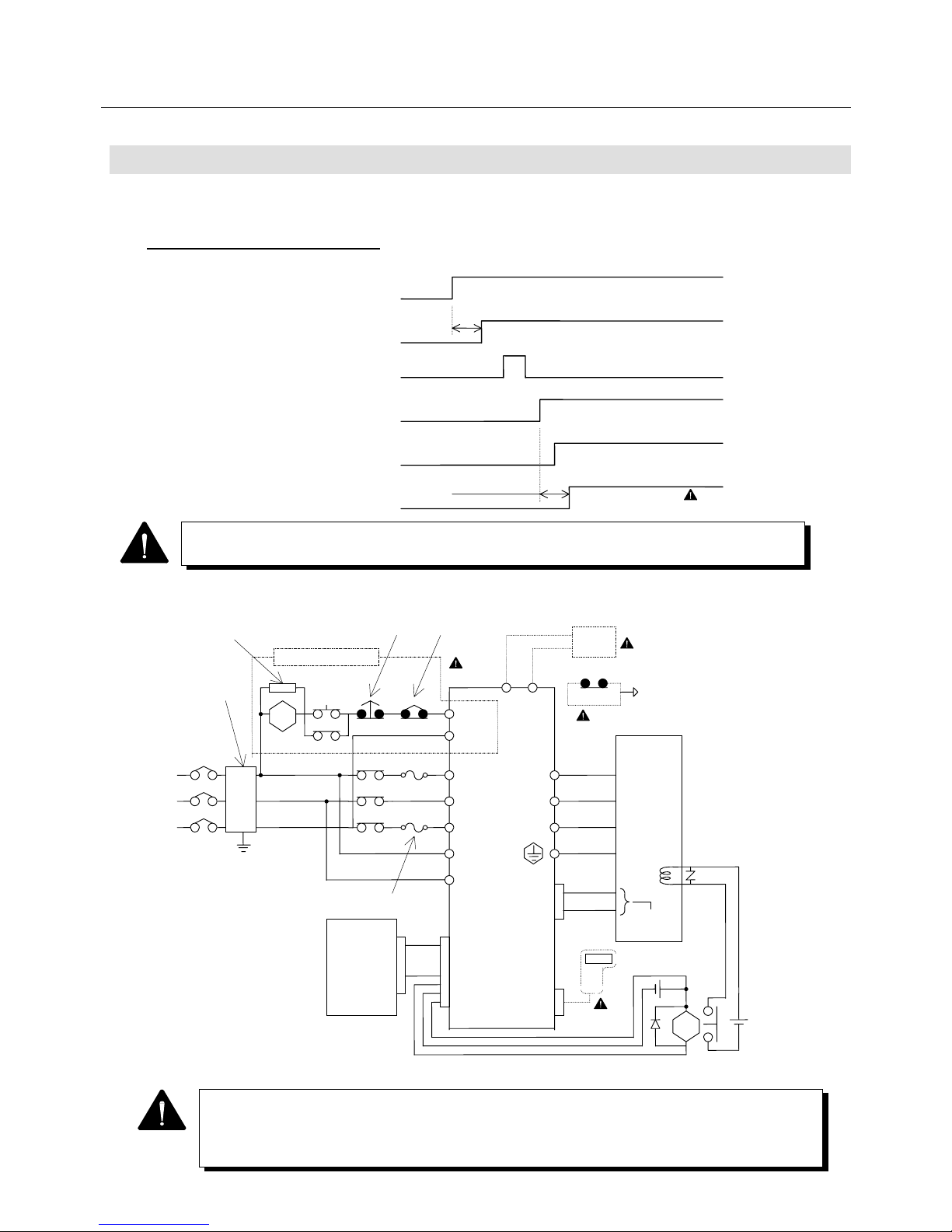
6. OPERATION
6-2
6.1 Operation Sequence
The frequency of power ON/OFF should be 10 times/H or less, and 50 times/day or less.
6.1.1 Power ON Sequence
Fig. 6-1
Control power ON (r, t)
Sequence power ON (CN1)
2.5 Sec
or less
A
mplifier ready output (RDY)
Start ready ON (external switch)
Main circuit power supply
(R, S, T)
Release
Dynamic brake release
A
pprox. 1.0 Sec
1
Start ready complete (SRDY)
1 The dotted line denotes an option.
2 RDY1 and RDY2 in the safety circuit are optional.
3 The thermostat output in the external regenerative resistor can be connected to
general-purpose input CN1 of the amplifier.
R
S
T
r
t
Install a spark killer
on the magnetic contactor
(Okaya Electric Industries Co.,
Ltd.: CRE-50500)
Safety circuit
3φ
200 V to
230 VAC
50 Hz to
External regenerative resistor:
Overheating detection thermostat
System
erro
r
Emergency
sto
p
Input to
CN1
External regenerative resisto
r
Start
read
y
DC power supply
for brake
Holding
brake
Fast-blown fuse
Prevention against
common/ normal
mode noise
Circuit
braker
2
PY
RDY1
MC
RDY2
MC
MC
Encoder
signal
CN1
CN2
MC
Controller
Motor
U
V
W
E
U
V
W
3
1
24 VDC
OP
1
MC
RY
Noise
filter
1 The time period from main circuit power ON to SRDY is approx. 1 sec. However, in
case of single phase power of Amplifier with 50A capacity, that will be approx. 1.5 sec.
Page 85
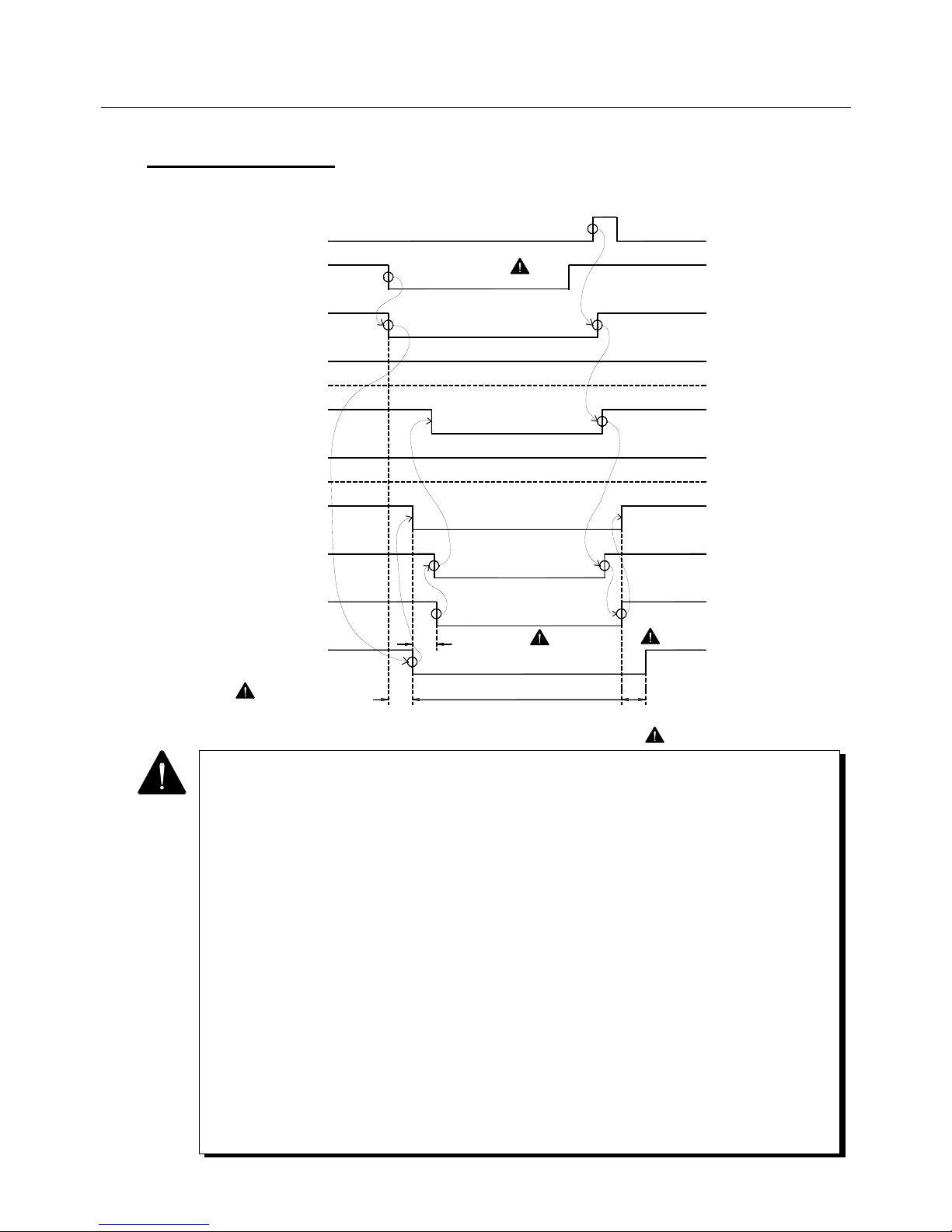
6. OPERATION
6-3
6.1.2 Stop Sequence
6.1.2.1 Stop and recovery due to emergency stop input
1 • Release "emergency stop" before inputting "start ready".
2 • The holding brake timing (standard value 300 ms, in Parameter Mode 1 on page 13) can
be changed to 0 to 1 sec. However, when it is set at 0 msec, command ineffective
(forced zero) status continues for 4 msec after SON.
• The current is limited by the sequence current limit value (standard value 120 %, in
parameter Mode 1 on page 12) between t2 and t3.
3 • It is possible to make commands ineffective (forced zero) during t3 after SON by setting
Func1 bit5 to "0" when setting parameters. In case of the position control type,
however, the command pulse remains as a deviation for t3.
• It is possible to make commands effective immediately after SON by setting Func1 bit5 to
"1" when setting parameters. However, the sequence current limit value is applied
when switching from SON to SOFF and is not applied when switching from SOFF to
SON.
4 • If an emergency stop occurs in a heavy load status, MPE (Main circuit Power Error,
alarm "9") may be activated.
5 • It is possible to output the command effectiveness from CN1-39 and 40 pins by using
parameter Func4.
6 • The time period from main circuit power ON to SRDY is approx. 1 sec. However, in
case of single phase power of Amplifier with 50A capacity, that will be approx. 1.5 sec.
7 • When the alarm generates, assemble the safety circuit outside of the amplifier.
Running away, injury, burning, fire, and secondary damage may be caused.
ON
OFF
ON
OFF
300 mSec
( 2)
Contact open
Start ready ON
(external switch)
Emergency stop
(EMR)
Main circuit power
supply (R, S, T)
Amplifier ready
output (RDY)
Dynamic brae
Servo ON
(SON)
Holding brake
excitation timing
output (HBON)
Start ready
complete output
(
SRDY)
Motor excitation
Command
effectiveness
output ( 5)
( 1)
300 mSec ( 2)
OFF
OFF
OFF
OFF
(holding brake operation)
ON (operating)
OFF
OFF
OFF
Command ineffective (forced zero)
Approx. 50 to 100 mSec
ON
Effective
ON
t1
t3
t2
ON
(release)
ON
OFF
O
N
ON
ON
ON
( 3)
(release)
Page 86
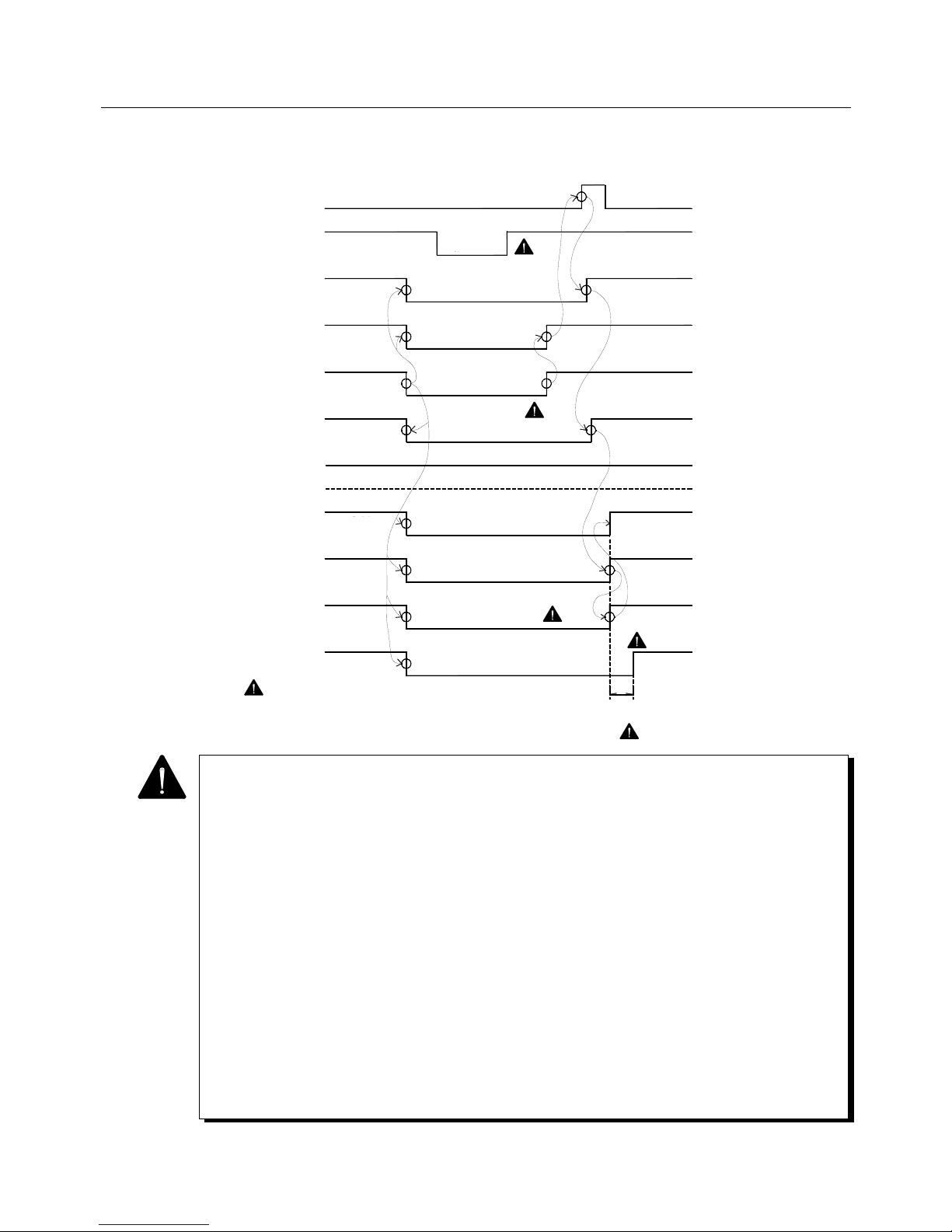
6. OPERATION
6-4
6.1.2.2 Stop and recovery due to an internal error
1 • In an internal error status, inputting "emergency stop" has no effect.
However, release it before inputting "start ready".
2 • As per the alarm reset sequence.
3 • The holding brake timing (standard value 300 ms, in Parameter Mode 1 on page 13) can
be changed to 0 to 1 sec. However, when it is set at 0 msec, command ineffective
(forced zero) status continues for 4 msec after SON.
• The current is limited by the sequence current limit value (standard value 120 %, in
parameter Mode 1 on page 12) within 300 msec.
4 • It is possible to make commands ineffective (forced zero) for 300 msec after SON by
setting Func1 bit5 to "0" when setting parameters. In case of the position control type,
however, the command pulse remains as a deviation for 300 msec.
• It is possible to make commands effective immediately after SON by setting Func1 bit5 to
"1" when setting parameters. However, the sequence current limit value is applied when
switching from SON to SOFF and is not applied when switching from SOFF to SON.
5 • It is possible to output the command effectiveness from CN1-39 and 40 pins by using
parameter Func4.
6 • The time period from main circuit power ON to SRDY is approx. 1 sec. However, in case
of single phase power of Amplifier with 50A capacity, that will be approx. 1.5 sec.
Contact
open
Start ready ON
(external switch)
Emergency stop
(EMR)
Main circuit power
supply (R, S, T)
Amplifier ready
output (RDY)
Dynamic brae
Internal abnormality
(ALM)
Servo ON
(SON)
Holding brake
excitation timing
output (HBON)
Start ready
complete output
(
SRDY)
Motor excitation
Command
effectiveness
output ( 5)
( 1)
OFF
OFF
OFF
(holding brake operation)
ON (operating)
OFF
ON
Command ineffective
(forced zero)
OFF
OFF
OFF
300 mSec
( 2)
ON
Effective
ON
ON
ON
t3
ON
ON
ON
ON
( 4)
( 2)
Page 87
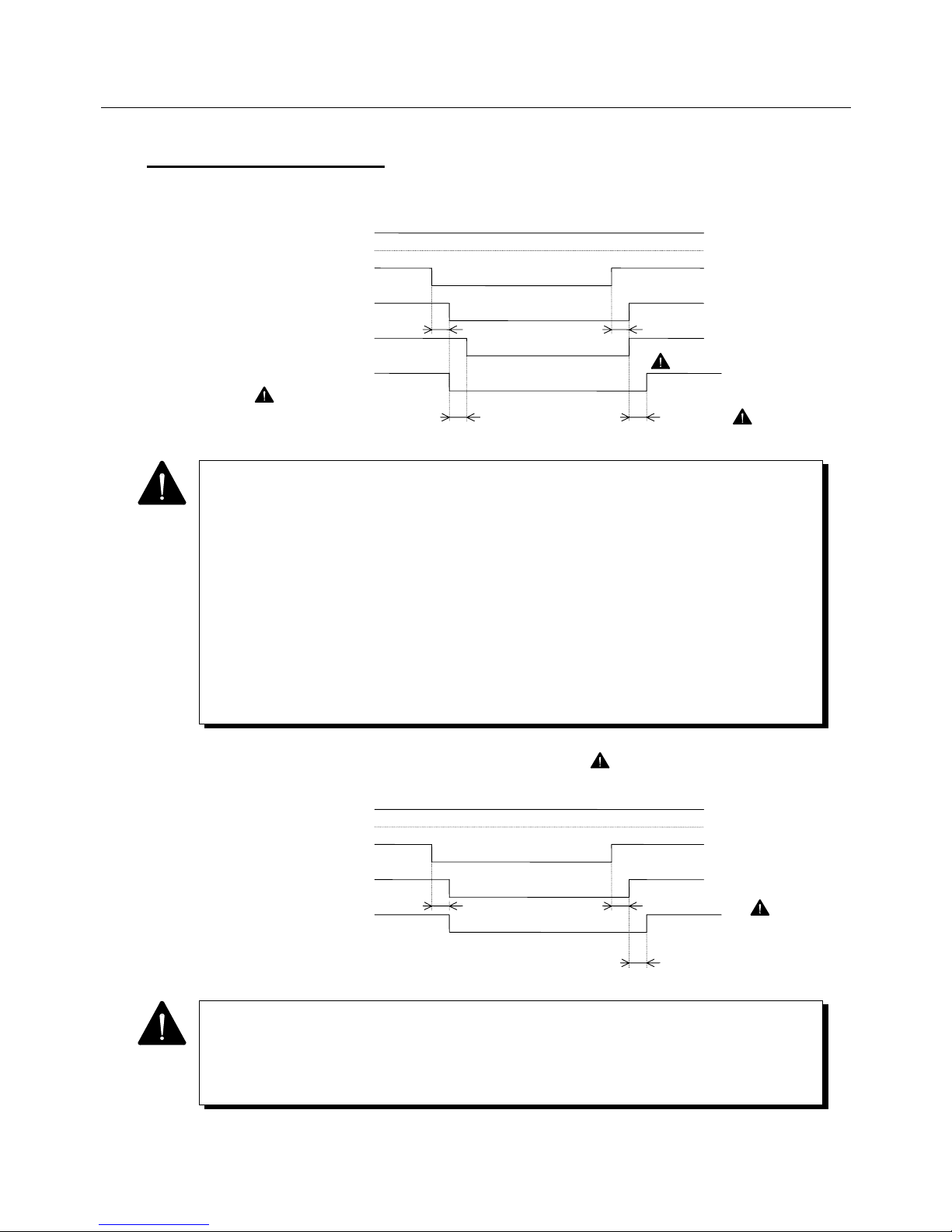
6. OPERATION
6-5
6.1.3 Servo OFF Sequence
6.1.3.1 When holding brake timing THB is set at 300 msec (standard)
6.1.3.2 When holding brake timing THB is set at 0 msec ( 1)
1 • The current is limited by the sequence current limit value (standard value 120%,
which is changed in Parameter Mode 1 on Page 12) for 300 mSec.
2 • It is possible to make commands ineffective (forced zero) for 300 msec after SON by
setting Func1 bit5 to "0" when setting parameters. In case of the position control
type, however, the command pulse remains as a deviation for 300 msec.
• It is possible to make commands effective immediately after SON by setting Func1
bit5 to "1" when setting parameters. However, the sequence current limit value is
applied when switching from SON to SOFF and is not applied when switching from
SOFF to SON.
3 • It is possible to output the command effectiveness from CN1-39 and 40 pins by using
parameter Func4.
1 This setting cannot prevent a self-weight fall by using "holding brake excitation timing
output". Secure command input timing that does not hold off braking.
2 It is possible to make commands effective immediately after SON regardless of THB
setting, by setting Func1 bit5 to "1" when setting parameters.
ON
( 2)
ON
Effective
Start ready
complete output (SRDY)
Servo ON (SON)
Holding brake excitation
timing output (HBON)
Motor excitation
Command effectiveness
output ( 3)
12 mSec or less
OFF
(
holding brake operation
)
300 mSec ( 1)
300 mSec or less
12 mSec or less
ON
(release)
ON
ON
ON
Command ineffective
(forced zero) OFF
OFF
ON
ON
OFF
OFF
ON
ON
Effective
Start ready
complete output (SRDY)
Servo ON (SON)
Motor excitation
Command effectiveness
out
p
ut
12 mSec or less ( 2)
12 mSec or less
ON
ON
ON
Command ineffective
(forced zero) OFF
OFF
ON
ON
OFF
OFF
OFF
ON
4 mSec
Page 88
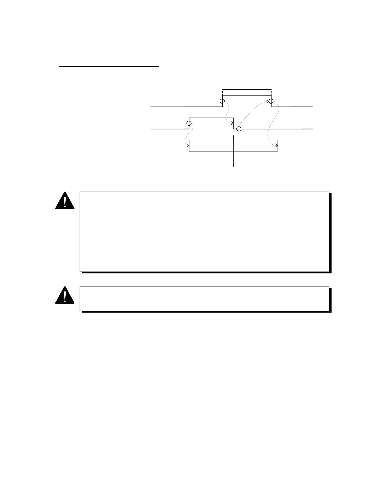
6. OPERATION
6-6
6.1.4 Alarm Reset Sequence
40 mSec or more
ON OFF
Output
Not output
ON
OFF
Display/alarm output clear
Reset input CN1-30
(23: common)
(RST)
Alarm code output or
alarm bit output
(ALM)
Amplifier ready
output (RDY)
1 Regarding the upper controller, turn off "reset input" after checking that no alarm occurs
by watching the alarm output.
2 When the alarm status continues in spite of "reset input", the alarm output is not cleared.
It is necessary to set a time-out period of 40 mSec or more to return "reset input" to the
original status.
3 Sensor error (DE), servo processor error (DSPE), memory error (MEME) and CPU error
(CPUE) cannot be reset unless the control power supply is turned off.
4 The battery alarm (AEE) output will not be cleared unless "encoder clear" is operated.
When turning the control power on or off to reset an alarm, allow a sufficient control power
off time. If the time is too short, another alarm may be issued.
Page 89
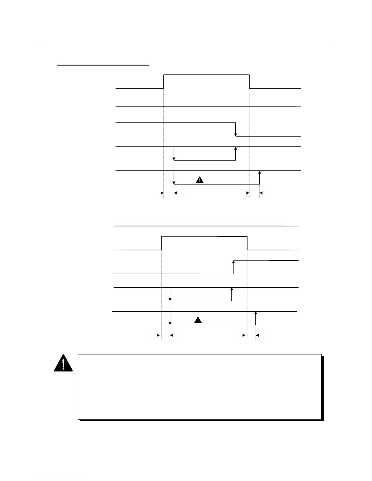
6. OPERATION
6-7
6.1.5 Overtravel Sequence
ON
Forward revolution
side overtravel
(PROT)
OFF
Backward revolution
side overtravel
(NROT)
Input command
Internal command
Backward revolution
command
Forward revolution
command
Input command
effective
Input command
effective
Current limit
Normal limit
Normal limit
12 mSec or less 12 mSec or less
OFF
OFF
Command ineffective
(forced zero)
Sequence current limit
value ( 2)
ON
OFF
OFF
OFF
Forward revolution
side overtravel
(PROT)
Backward revolution
side overtravel
(NROT)
Input command
Internal command
Current limit
12 mSec or less 12 mSec or less
Normal limit
Normal limit
Sequence current limit
value ( 2)
Input command
effective
Input command
effective
Command ineffective
(forced zero)
Forward revolution
command
Backward revolution
command
1 Operation of command invalidation (forced zero) differs between the position and
velocity control types. For the position control type, command pulses are inhibited, and
for the velocity control type, the velocity command becomes zero (VCMD = 0).
These settings are validated when the acceleration/deceleration time (Tvac, Tvde) or
low pass filter (VLPF) parameter is set.
2 Sequence current limit value can be changed by SILM in the Parameter Mode 1 on
Page 12.
Page 90
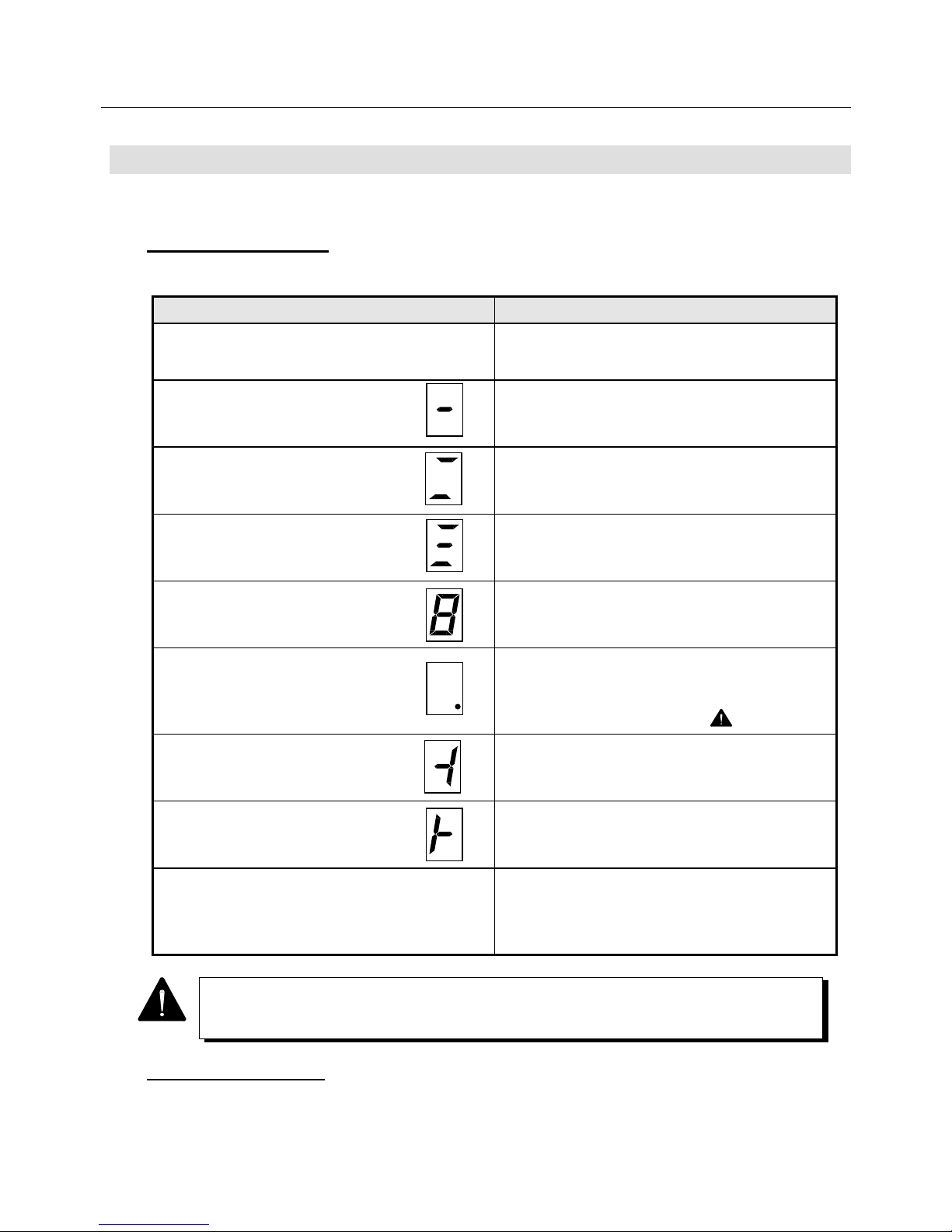
6. OPERATION
6-8
6.2 Display
The Servo Amplifier status and alarms are displayed by LED and 7-segment LED.
6.2.1 Status Display
Table 6-1 Status Display
Display Explanation of status
LED POWER ON
The control power supply of +5 V is set up.
7-segment LED
The control power supply (r, t) is set up and the
"amplifier ready output (RDY)" signal is ON.
7-segment LED
The main power supply (R, S, T) is being turned on
or set up but the "start ready complete" signal is
OFF.
7-segment LED
The main power supply (R, S, T) is set up and the
start ready complete" signal is ON.
7-segment LED
Rotates in the form of the figure 8.
The "Servo ON" signal is ON.
7-segment LED
This indicates a battery warning status due to the
lowering of the external battery power when an
absolute encoder is used.
(Replace the external battery.)
7-segment LED
In the position/velocity control type, the forward
revolution side is in an overtravel status.
7-segment LED
In the position/velocity control type, the backward
revolution side is in an overtravel status.
LED CHARGE ON
The smoothing capacitor of the main power supply
is being charged.
<While this LED is ON, be careful about a high
voltage.>
6.2.2 Alarm Display
For alarm display, refer to the paragraph pertaining to troubleshooing in "Maintenance".
When the alarm history is displayed by 7-segment LED, the battery warning "." is not
displayed.
Page 91
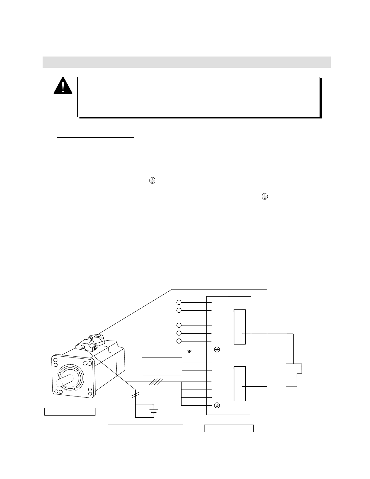
6. OPERATION
6-9
6.3 Be Sure to Check the Functioning at First
6.3.1 Minimum Wiring
1 Wire 200 VAC to terminals r and t of connector CNA of the Servo Amplifier
(hereinafter referred to "amplifier").
2 Wire 200 VAC to terminals R, S and T of amplifier connector CNA.
Ground the PE (protective earth ) terminal of the amplifier.
3 Wire the motor power lines to the U, V and W terminals as well as to the PE ( ) terminals of the
amplifier connector CNB. (For amplifiers having 15 A or 30 A capacity, connect an external
regenerative resistor between the P and Y (or COM) terminals of the connector CND.)
4 Wire the encoder cable to amplifier connector CN2.
5 Connect the remote operator to the amplifier connector OP.
6 When a brake is fitted with the motor, apply a specified voltage to the brake cable and release the
brake.
The parameter setting at the first power ON is assumed to be a standard setting.
In taking a runaway into consideration, be sure to fasten the motor to a fixing table or the
like, and also do not apply any load to its shaft side.
Wire the power supply so that it can be immediately cut off in case of an emergency.
Remote operator
⑤
④
U
V
W
P
Y
CN2
OP
R
S
T
r
t
①
Regenerative
resistor
90 VDC or
24 V
③
②
200 VAC
200 VAC
Servo Amplifier
Holding brake power supply
Servomotor
Page 92
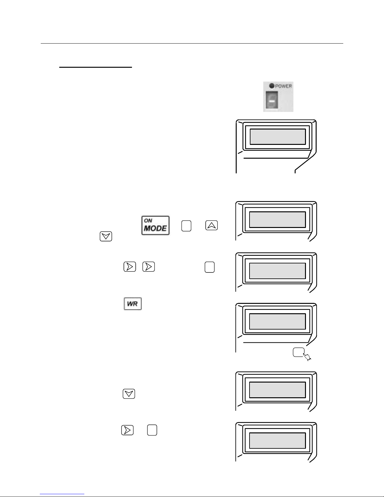
6. OPERATION
6-10
6.3.2 Jog Operation
7 Turn ON the 200 VAC of r-t (① wires).
→ The servo amplifier POWER and the right-hand
figure portion of 7-segment LED are lighted.
→ When the 7-segment LED displays "U", proceed to
section 6.4.
→ The remote operator screen display becomes the
[Push Mode Key] screen as shown on the right and
a "beep" sound is emitted.
Push〔MODE〕ke
y
8 Change the remote operator setting and reset the
OT (over travel) signal.
The procedure is as follows:
Repeat pushing , and or
keys
until the right screen appears.
Push the , key twice and the key
once so that the right screen will appear.
Push the key so that the right screen will
appear.
*Para. Set3 1
Func0 : 00000000
*Para. Set3 1
Func0 : 00100000
WR
Completed 1
Func0 : 00100000
9 Make the JOG operation function effective using
the remote operator.
Push the key a few times until the right
screen appears.
Push the and keys in that order so that
the right screen will appear.
*Para. Set3 7
Func6 : 00000000
*Para. Set3 7
Func6 : 01000000
1
2
1
Page 93
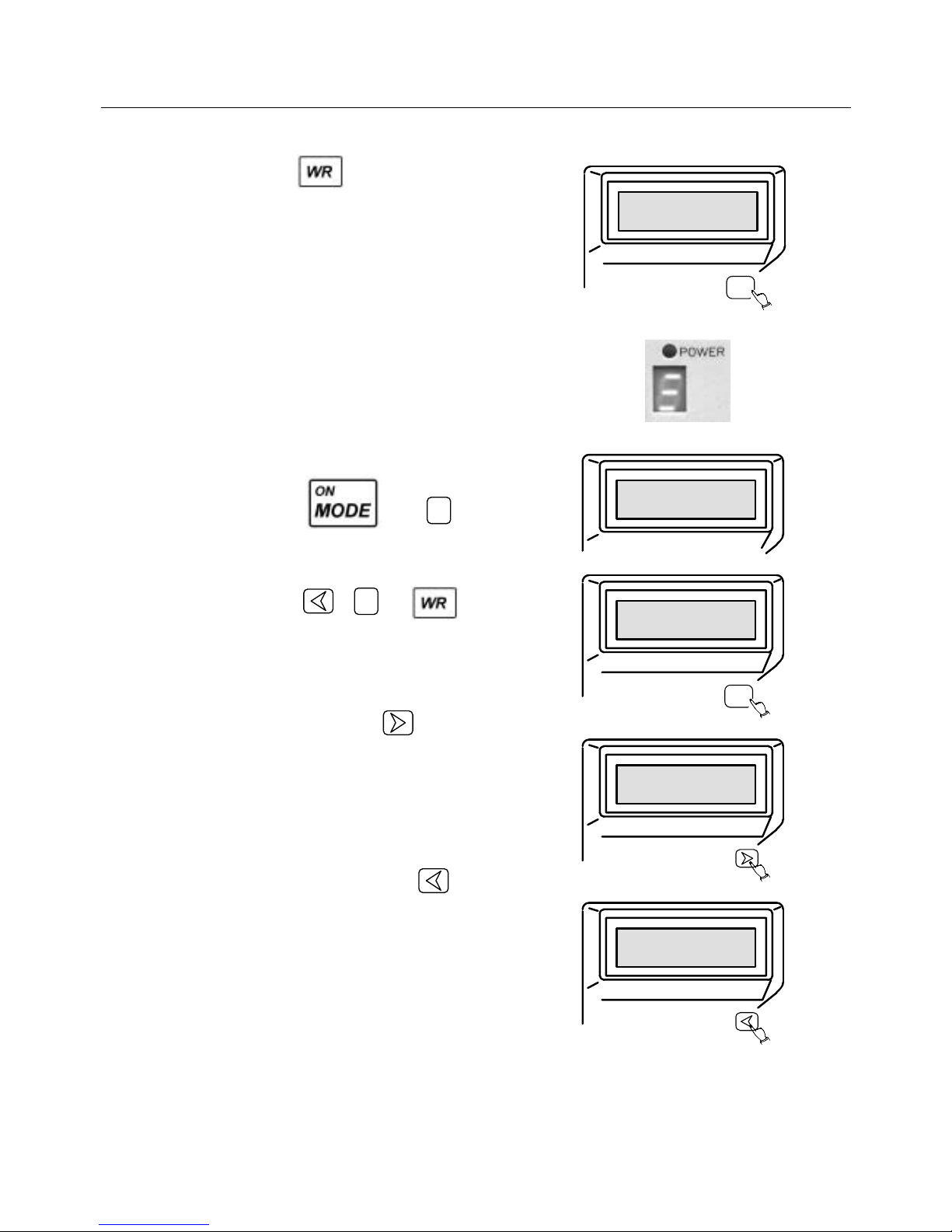
6. OPERATION
6-11
Push the key so that the right screen will
appear.
(Func6 bit6 “1” described above returns to “0” by
turning the power on again.)
WR
Completed 7
Func6 : 01000000
10 Turn on the 200 VAC (② wires) of R-S-T.
The 7-segment LED is light as shown in the right
figure.
11 Start the JOG operation.
Push the and keys so that the
right screen will appear.
Push the , and keys so that the
right screen will appear.
The 7-segment LED draws a figure of 8.
Continue pushing the key until the right
screen appears.
The remote operator keeps sounding "beep, beep"
and the motor rotates counterclockwise (CCW) in
10 min
−
1
when viewed from its shaft side.
Then continue pushing the key until the right
screen appears.
In this mode, the motor rotates clockwise (CW) in
10 min
−
1
.
*Test
0
JOG Set min
-1
WR
*Test
0
JOG Set 10min
-1
*Test
0
JOG Fwd Running
*Test
10
JOG Rvs Running
7
1
Page 94
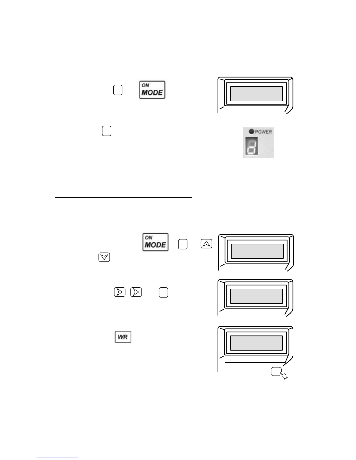
6. OPERATION
6-12
12 Return to original mode.
Push the and keys so that the
right screen will appear.
The key in the 7-segment LED flickers.
By this, the JOG operation ends.
*
Mode select
*
Push〔0〕to
〔7〕
ke
y
6.3.3 Resetting and Turning the Power Off
13 Change the remote operator setting and reset the
OT.
Then, operate the remote operator according to the
following procedure.
Repeat pushing the , and
or keys until the right screen appears.
Push the , and keys so that the
right screen will appear.
Push the key so that the right screen will
appear, completing operation.
*Para. Set3 1
Func0 : 00100000
*Para. Set3 1
Func0 : 00000000
WR
Completed 1
Func0 : 00000000
14 Turn off the 200 VAC of R-S-T.
15 Turn off the 200 VAC of r-t.
16 If the brake is fitted with the motor, turn off the brake
power.
d
0
2
0
Page 95
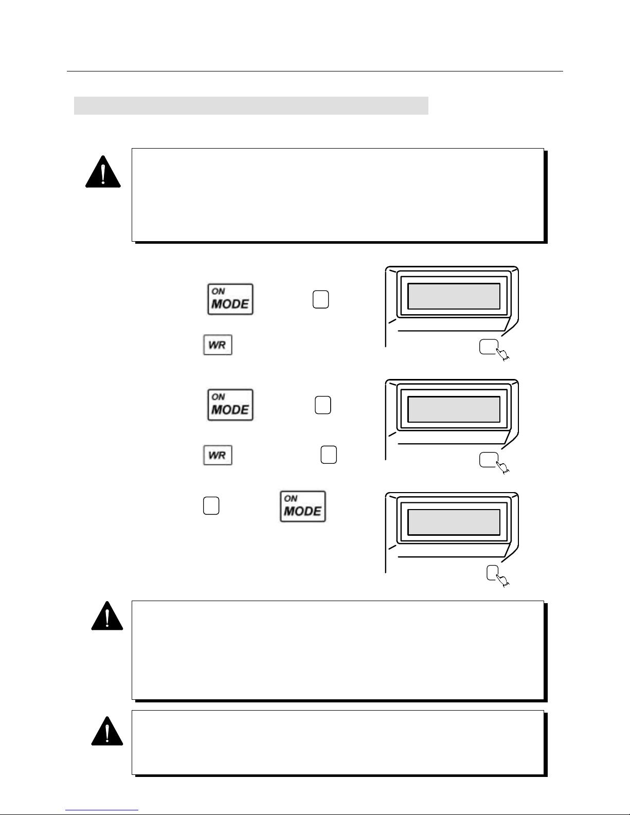
6. OPERATION
6-13
6.4 Encoder Clear Using Remote Operator
(When Absolute Encoder is Used)
1 Make the test mode effective.
Press the key and the key, then
select Func6 and set the bit6 to "1".
Press the key.
2 Perform ECLR.
Press the key and the key, then
select ELCR on page 4.
Press the key, and press the key
down for 4 seconds or more.
Press the key and the key to
terminate the test mode.
3 Turn on the power again.
The alarm "U" will be cleared.
WR
*
Para. Set3 4
Func6 : 01000000
WR
*Test
4
ECLR Clear 〔WR
〕
3
*Test
4
ECLR Rdy Y=3,N=0
2
7
3
0
When the power is first turned on after the amplifier and the motor are wired, the alarm "U"
(battery alarm) may come on even though a lithium battery is connected. This is because,
when an absolute encoder is used, the absolute position is not fixed inside the encoder if the
battery backup is less than 20 hours, causing an alarm to be output. The encoder can be
cleared without wiring for CN1 encoder clear signal by executing ECLR (mode 7, page 4)
using the remote operator and turning the power on again, which releases the battery alarm.
1 Our recommendation: Use a Toshiba lithium battery (ER6V: 3.6 V, 2,000 mAh).
The battery life is estimated at approximately 6 years.
2 On the ABS-E absolute encoder, alarm "8" (sensor error) may be issued after the power
is turned on for the first time after the amplifier or motor is wired. This is because the
voltage to be supplied to the sensor is lowered due to charging to the capacitor in the
encoder. The alarm can be reset by turning the control power on again.
In case of use without connecting retium battery in an application not using multiple
rotational data for wiring-saved absolute sensor (ABS-E.S1), set Func6, bit5 to “1” before
turning control power ON again. Thus, alarm “U” (battery alarm) shall not be detected
when turning control power ON again.
Page 96

7. EXPLANATION OF PARAMETERS
7-1
EXPLANATION OF PARAMETERS
7.1 Remote Operator (Optional) ........................................................ 7-2
7.1.1 Outline of Remote Operator .............................................. 7-2
7.1.2 Function Table .................................................................. 7-3
7.1.3 Basic Operation Procedure ...............................................7-4
7.1.4 Parameter Setting Mode
(Screen Mode 0 to 2 and 8) .............................................. 7-5
7.1.5 Parameter Increment/Decrement Mode
(Screen Mode 3) ............................................................... 7-8
7.1.6 Parameter Select Mode (Screen Mode 4)......................... 7-10
7.1.7 Monitor Mode (Screen Mode 5)......................................... 7-12
7.1.8 Alarm Trace Mode (Screen Mode 6) ................................. 7-14
7.1.9 Test Mode (Screen Mode 7).............................................. 7-17
7.1.9.1 JOG Operation .................................................. 7-18
7.1.9.2 Offline Automatic Tuning Function .................... 7-20
7.1.9.3 Automatic Notch Filter Tuning Function ............ 7-22
7.1.9.4 Automatic Offset Function................................. 7-24
7.2 Description of Parameters ........................................................... 7-26
7.2.1 Block Diagram of Position Control Type Parameters ........ 7-26
7.2.2 Parameter Summary Table ............................................... 7-27
7.2.3 Parameter List................................................................... 7-30
Page 97
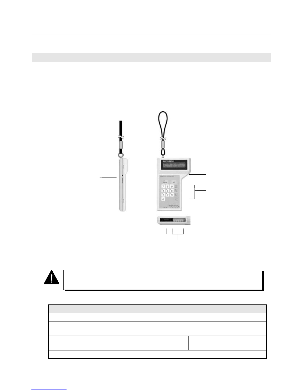
7. EXPLANATION OF PARAMETERS
7-2
7.1 Remote Operator (Optional)
This section explains the basic operation of the remote operator. By using the remote operator, parameter
change, monitoring of velocity and current, alarm trace and various tests are possible.
7.1.1 Outline of Remote Operator
The following figure shows the remote operator.
Fig. 7-1 Remote Operator
Table 7-1 Specifications of Remote Operator
Item Specification
Power supply Supplied from the Servo Amplifier
Connection method Connector connection using an exclusive cable
(cable length: 2 m)
Ambient temperature During operation status
0°C to +50°C (32°F to 122°F)
During storage
−20°C to +65°C (-4°F to 149°F)
Working atmosphere Free from oil mist, corrosive gas and dust
Hand Band
Liquid crystal panel
(16 characters × 2 lines)
Operation keys
Connector to
the amplifier Check pin
Brightness
adjusting control
Since the liquid crystal panel may be broken if the remote operator is dropped, handle it with
care.
Page 98
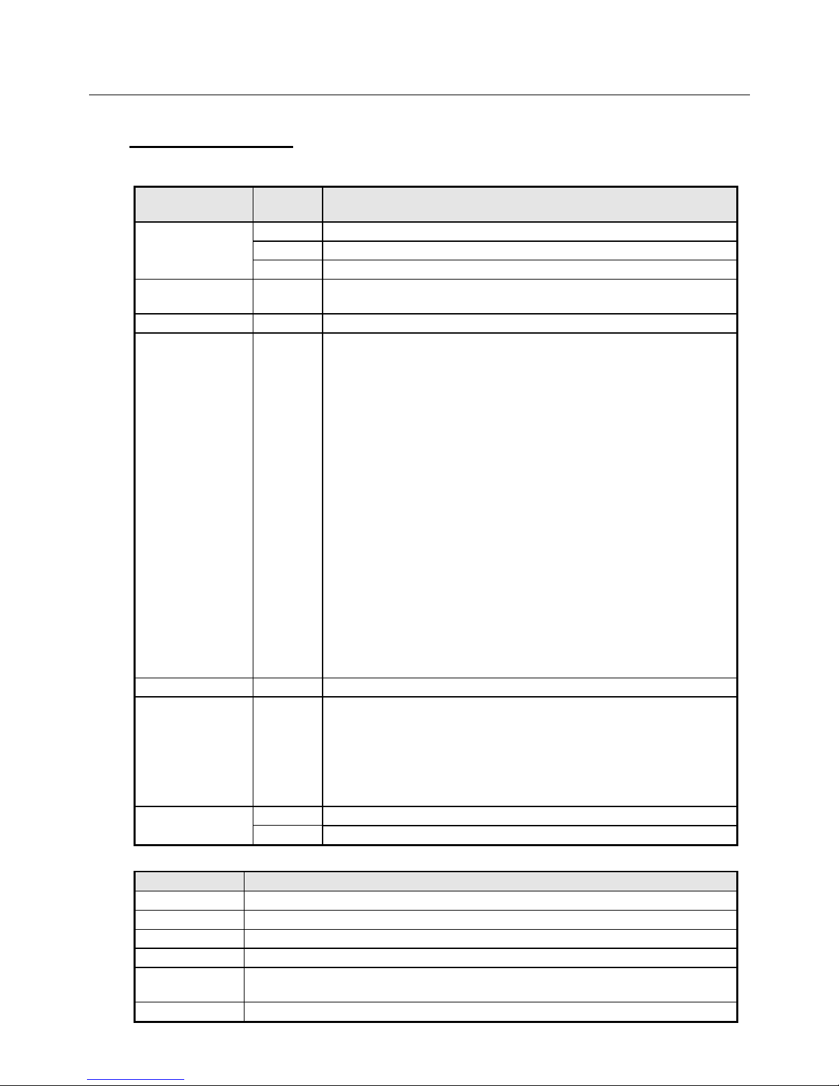
7. EXPLANATION OF PARAMETERS
7-3
7.1.2 Function Table
Table 7-2 Functions of Remote Operator
Mode Screen
No.
Function
Setting mode 0 Directly enters user parameters by key-in operation.
1 Directly enters user parameters by key-in operation.
2 Directly enters user parameters by key-in operation.
Up/down mode 3 Allows values to be incremented or decremented using the "1"
(increment) and "0" (decrement) keys.
Select mode 4 Allows user parameters to be selected from the screen display.
Monitor mode 5 Displays various monitors on the screen.
• Status monitor
• Input monitor
• Output monitor
• Velocity command
• Velocity
• Current command
• Current
• Position deviation counter value
• U-phase electric angle
• Position command frequency
• Absolute value
• Position free-run counter value
• Estimated effective torque value
• Position loop gain
• Velocity loop proportional gain
• Velocity loop integral time constant
• Current command low pass filter setting value
• Built-in regenerative resistor absorbed power
Alarm trace mode 6 Display 8 alarms (the current one plus the past seven alarms)
Test mode 7 Allows various test modes to be operated:
• JOG operation
• Offline automatic tuning
• Automatic offset (velocity and torque commands)
• Encoder clear
• Automatic notch filter tuning
8 Allows user parameters to be entered directly from the key pad. Setting mode
9 Allows user parameters to be entered directly from the key pad.
Table 7-3 Functions of Remote Operator Check Pin
Name Description
VCMD Monitors the velocity command (CN1 - 21 pin input).
M1 Monitors the same as the amplifier monitor 1 output.
M2 Monitors the same as the amplifier monitor 2 output.
SG Signal ground. (Common to amplifier SG)
DM1 Outputs the internal status to the monitor (motor excitation). (It goes high when the
motor is excited.)
DM2 Outputs the internal status to the monitor (alarm). (High when the alarm is on.)
Page 99
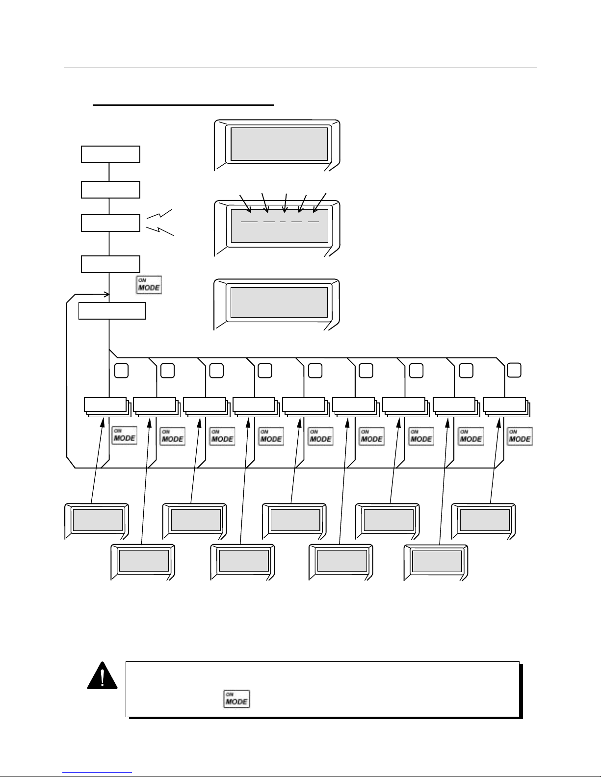
7. EXPLANATION OF PARAMETERS
7-4
If a no-operation status continues for about 3 minutes, the liquid crystal display disappears.
To re-start, press the key.
7.1.3 Basic Operation Procedure
Fig. 7-2 Basic Operation of Remote Operator
Powering on
Communication
status
Communication
ready complete
Initial screen
Mode select screen
Selected screen
appears
Remote Operator
<Ver. #. ##>
*Mode Select *
Push[0]to[7]Key
*Para. Set. 1
―――――――――
*Para. Set. 3
―――――――――
*Para. Select.-
―――――――――
*Alarm ―――
―――――――――
*Para. Set. 4
―――――――――
*Para. Set. 2
―――――――――
*P.UP=1,Down=0
―――――――――
*Monitor -
―――――――――
*Test ―――
―――――――――
*###-##-#-0#-##*
Push [MODE] Key
(3-phase 200 V
power supply specification)
キー入力画
Key-in
screen
キー入力画
Key-in
screen
キー入力画
Key-in
screen
キー入力画
Increment/
decrement screen
キー入力画
Select
screen
キー入力画
Alarm trace
screen
キー入力画
Test
screen
キー入力画
Key-in
screen
キー入力画
Monito
r
screen
8
7 6 5
4
32 1 0
Moto
r
code
AMP
capacityTYPE
CPU
version
DSP
version
Peep
Page 100
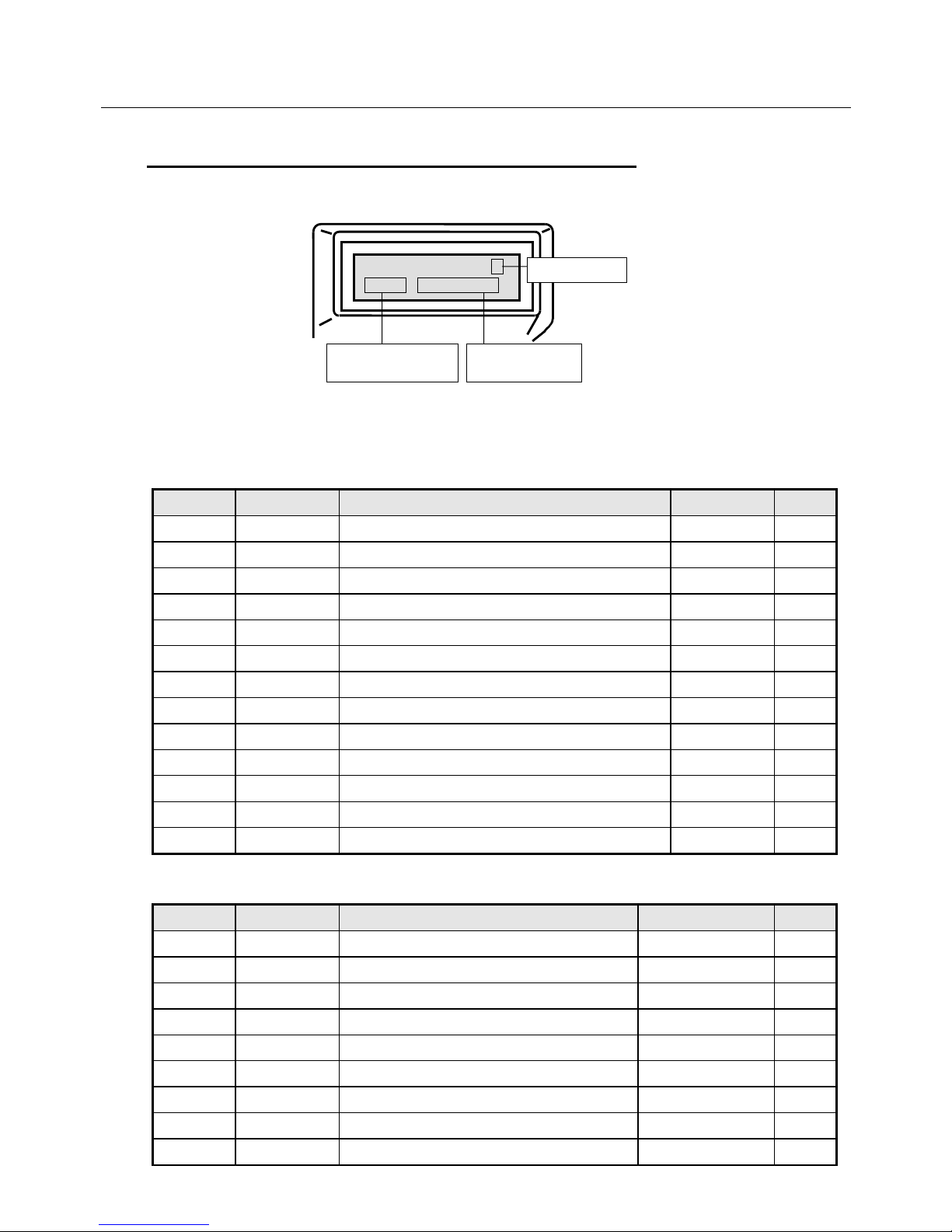
7. EXPLANATION OF PARAMETERS
7-5
7.1.4 Parameter Setting Mode (Screen Mode 0 to 2 and 8)
Various Servo Amplifier parameters can be directly set in this mode from the keys.
Fig. 7-3 Parameter Setting Mode Screen
Table 7-4 Parameters for Screen Mode 0
Page No. Abbreviation Name Setting range Unit
0 KpM Monitors position loop gain - rad/S
1 KffM Monitors feed forward gain - %
2 KvpM Monitors velocity loop proportional gain - Hz
3 TviM Monitors velocity loop integral time constant - mSec
4 FLPM Monitors feed forward LPF - Hz
5 VLPM Monitors velocity command LPF - Hz
6 ILPM Monitors current command LPF - Hz
7 BFAM Monitors current command BEFA - Hz
8 BFBM Monitors current command BEFB - Hz
9 Tpcm Position command LPF time constant 0 to 4000 mSec
10 Tvac Velocity command acceleration time 0 to 9999 mSec
11 Tvde Velocity command deceleration time 0 to 9999 mSec
12 KvpA Velocity loop proportional gain addition value 0 to 255 Hz
Table 7-5 Parameters for Screen Mode 1 (1/2)
Page No. Abbreviation Name Setting range Unit
0 INP Positioning complete signal width 1 to 32767 P (+/−)
1 OVF Excess deviation over value 1 to 32767 ×256P
2 EGER Electronic gear ratio 1/32767 to 32767/1
3 PMUL Command pulse multiplier 1 to 63
4 ENCR Output pulse dividing ratio 1 to 8192
5 LTG Low speed 0 to 32767 min-1
6 HTG High speed 0 to 32767 min-1
7 SPE Speed matching width 0 to 32767 min-1
8 VCI1 Internal velocity command value 1 0 to 32767 min-1
*Para. Set #
#### #########
Screen page
(Any number from
1 to 4 is entered in “$”.)
Set parameter
value
Abbreviated
p
arameter name
 Loading...