

Sanyo SUPER BL P5,SUPER BL PY2,SUPER BL PY User Manual
M0001584J
AC SERVO SYSTEM
BL Super Series
PY2
PY2 Servo Amplifier Instruction Manual
Released September 1999
Revision F April 2001
Revision J August 2003
SANYO DENKI CO.,LTD English
E

This product does not qualify as strategic goods as specified by the Foreign Exchange
and Foreign Trade Control Law. Accordingly, applying for an export permit from the
Ministry of Economy, Trade & Industry is not required. For customs purposes, however,
an explanation may be required. So, please ask us for the material explaining that this
product is not applicable. In addition, when this product is incorporated into other
equipment, the applicable regulations must be complied with.
i
PREFACE
The "PY" series Servo Amplifier is applicable to a wide range of applications from small to medium
capacity thanks to its multiple functions, high performance, downsizing and high cost performance.
The "PY2" was developed as an upgraded version of this "PY" series to satisfy customer needs for
further downsizing.
The "PY2" Servo Amplifier features the same performance as the "PY" series, on which it is based,
with only the size reduced. The small and high performance "PY2" Servo Amplifier is useful for a
large number of customers in applications requiring space saving.
This User's Manual explains the functions, wiring, installation, operation, maintenance and
specifications of the "PY2" Servo Amplifies and our Servomotors.
To completely utilize all functions of the "PY2" series, read this manual carefully before use to
ensure proper operation.
After reading this manual, keep it handy so that it can be referred to by anyone at anytime.
In this manual,
"AC Servomotor" is sometimes abbreviated to "Servomotor" or "Motor".
"AC Servo Amplifiers" to "Servo Amps." or "Amps.".
Also, "Wiring-saved incremental encoders" and "Request signal-unavailable
absolute encoders" are sometimes abbreviated to "Encoders" and "Wiring-saved
incremental encoders", "Request signal-unavailable absolute encoders" and
"Request-available absolute sensors" to "Sensors".
i
International Standard Compliance
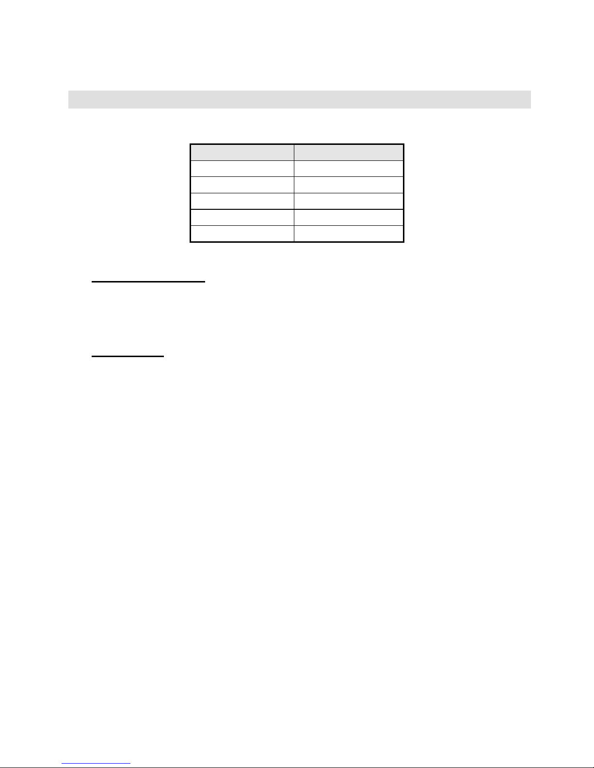
The “PY2” Servo Amplifier complies with the following International standards.
International standard Standard No.
TÜV EN50178
UL UL508C
CUL UL508C
Low Voltage Directive EN50178
EMC Directive EN55011
Working Environment
Since the working environment for the “PY2” Servo Amplifiers must be pollution level 2 or above (i.e. level 1
or 2) as specified in EN50178, be sure to use them in a pollution level 1 or 2 environment.
Power Supply
The “PY2” Servo Amplifiers must be used under the conditions specified in overvoltage category II, EN
50178. Use a reinforced insulation transformer conforming to the EN Standard for power supply input.
For the interface, use a DC power supply whose input and output sections have reinforced-insulation.
i
CE Marking
At Sanyo Denki, we are executing tests on the “PY2” Servo Amplifier for compliance with the CE marking at
qualifying institutions. The CE mark is required to be attached all end products sold in EU countries.
Only products conforming to the safety standards are permitted to have them. Accordingly, customers are
requested to perform the final conformity test on their machines or systems incorporating our amplifiers.
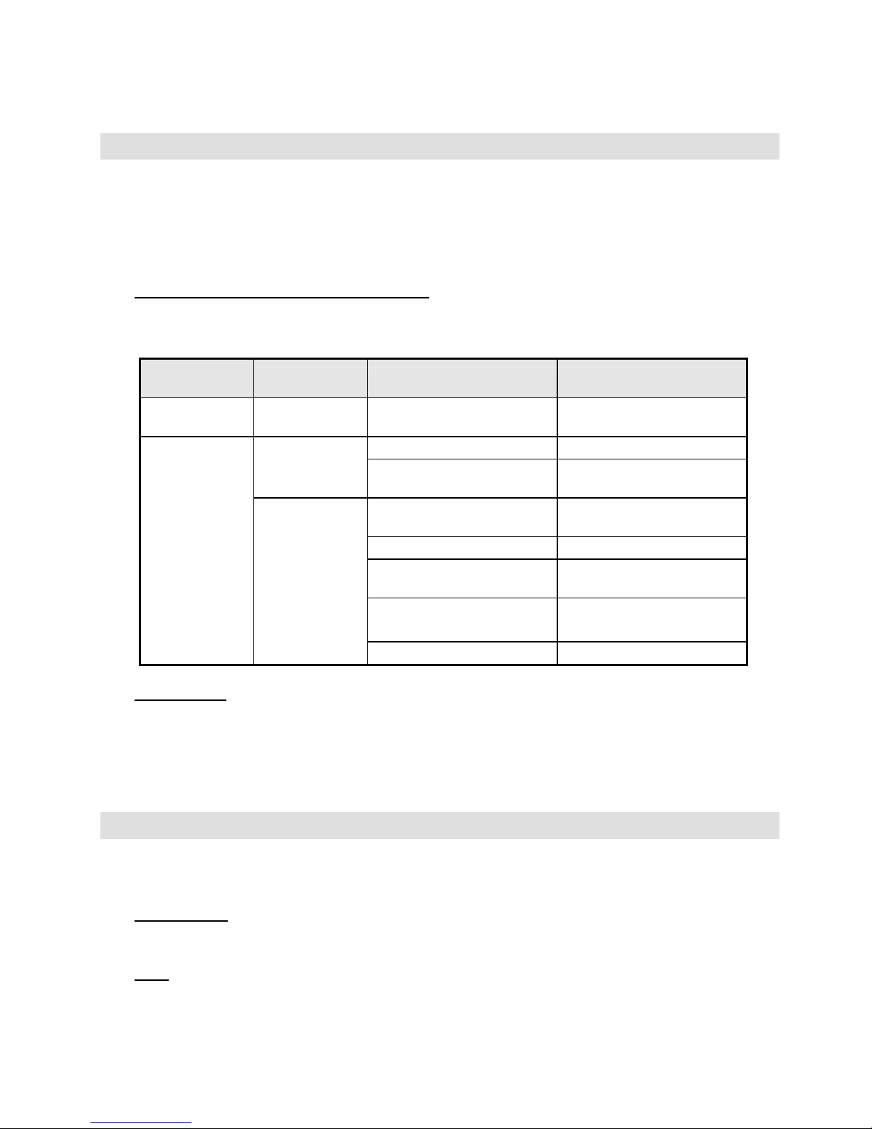
The CE Marking Conformity Standards
We execute conformity tests for the following standards on the “PY2” Servo Amplifier at qualifying
institutions.
Classification of
directive
Classification Test Test standard
Low Voltage
Directive
- - EN50178
Terminal interference voltage EN55011
Emission
Electromagnetic radiation
interference
EN55011
Radiation field immunity
EN61000-4-3 / 1996
ENV50204 / 1995
Conductivity immunity EN61000-4-6 / 1996
Electrostatic immunity
EN61000-4-2
EN61000-4-2 : A1 / 1998
Electrostatic immunity
EN61000-4-2
EN61000-4-2 : A1 / 1998
EMC Directive
Immunity
Burst immunity EN61000-4-4 / 1995
File numbers
Low Voltage Directive, Declaration : File No. C0002827C
Low Voltage Directive, Certification : File No. B 01 05 21206 040 (Messrs. TÜV PRODUCT SERVICE)
EMC Directive, Declaration : File No. C0004056
EMC Directive, Certification : File No. E9 99 05 30982 005 (Messrs. TÜV PRODUCT SERVICE)
UL Marking
The “PY2” series products are qualified to have the UL (U.S. version) and cUL (Canada version) marks of
the Underwriters Laboratories attached.
File Numbers
File No.: E179775 Power Conversion Equipment (CCN: NMMS, NMMS7)
Fuse
The “PY2” Servo Amplifiers are not equipped with fuses. Customers are requested to prepare a
UL-approved fast-blown fuse and install it in the input section of the main circuit power supply.

iv
CONTENTS
0. SAFETY PRECAUTIONS
0.1 Introduction ..................................................................................................................... 0-2
0.2 "Warning Label" Location on Product ............................................................................. 0-2
0.3 Meaning of Warning Indication ....................................................................................... 0-3
0.3.1 Details of Indications ........................................................................................... 0-3
0.3.2 Rank of Cautions on Safety................................................................................. 0-3
0.3.3 Symbolic Indication.............................................................................................. 0-4
0.4 Cautions on Safety .........................................................................................................0-5
1. BEFORE OPERATION
1.1 Precaution on Unpacking ................................................................................................. 1-2
1.2 Confirmation of the Product.............................................................................................. 1-2
1.3 Precautions on Operation................................................................................................. 1-2
1.4 How to Read Model Numbers .......................................................................................... 1-6
1.4.1 Model Number of Servomotor ............................................................................. 1-6
1.4.2 Model Number of Servo Amplifier ....................................................................... 1-7
1.5 "PY2" Servo Amplifier Standard Combination.................................................................. 1-8
1.6 Flowchart for Determining Servomotor
Model Number .................................................................................................................. 1-9
2. FUNCTION, CHARACTERISTICS AND CONFIGURATION
2.1 "PY2" Servo Amplifier Built-in Functions.......................................................................... 2-2
2.2 Characteristics of "PY2" Servo Amplifier.......................................................................... 2-6
2.3 Characteristics of Servomotor .......................................................................................... 2-11
3. SERVO SYSTEM CONFIGURATION
3.1 Block Diagram .................................................................................................................. 3-2
3.2 External Mounting and Wiring Diagram............................................................................ 3-2
3.3 Names of Servo Amplifier Parts ....................................................................................... 3-3
3.3.1 PY2A015/030 ...................................................................................................... 3-3
3.3.2 PY2E015/030 ...................................................................................................... 3-4
3.3.3 PY2A050 ............................................................................................................. 3-5
3.4 Optional Peripheral Equipment List.................................................................................. 3-6
4. WIRING
4.1 Applicable Wire Sizes.......................................................................................................4-2
4.2 Specifications of Sensor Cable ........................................................................................ 4-3
4.3 External Wiring Diagram................................................................................................... 4-4
4.3.1 External Wiring Diagram (200 VAC Input Type) ................................................. 4-4
4.3.2 External Wiring Diagram (100 VAC Input Type) ................................................. 4-6

v
4.3.3 Sensor Connection Diagram (INC-E).................................................................. 4-8
4.3.4 Sensor Connection Diagram (ABS-E) ................................................................. 4-9
4.3.5 Sensor Connection Diagram (ABS-RII) .............................................................. 4-10
4.3.6 Sensor Connection Diagram (ABS-E.S1) ........................................................... 4-11
4.4 Connector Terminal Arrangement Input/Output Signal Diagram..................................... 4-12
4.4.1 CN1: Interface Connector.................................................................................... 4-12
4.4.2 CN2: Sensor Connector ...................................................................................... 4-13
4.5 Wiring Procedure.............................................................................................................. 4-15
4.6 Precautions on Wiring ...................................................................................................... 4-16
4.6.1 Recommended Surge Protector.......................................................................... 4-17
4.6.2 CN1 & CN2 Shielding Procedure ........................................................................ 4-18
4.6.3 Typical CN2 Compression Insert Application...................................................... 4-20
5. INSTALLATION
5.1 Servo Amplifier Installation............................................................................................... 5-2
5.1.1 Installation Place ................................................................................................. 5-2
5.1.2 Installation Procedure.......................................................................................... 5-3
5.2 Servomotor Installation.....................................................................................................5-4
5.2.1 Installation Place ................................................................................................. 5-4
5.2.2 Installation Procedure.......................................................................................... 5-4
5.3 Cable Installation .............................................................................................................. 5-9
6. OPERATION
6.1 Operation Sequence......................................................................................................... 6-2
6.1.1 Power ON Sequence........................................................................................... 6-2
6.1.2 Stop Sequence .................................................................................................... 6-3
6.1.3 Servo OFF Sequence.......................................................................................... 6-5
6.1.4 Alarm Reset Sequence ....................................................................................... 6-6
6.1.5 Overtravel Sequence........................................................................................... 6-7
6.2 Display.............................................................................................................................. 6-8
6.2.1 Status Display...................................................................................................... 6-8
6.2.2 Alarm Display ...................................................................................................... 6-8
6.3 Be Sure to Check the Functioning at First ....................................................................... 6-9
6.3.1 Minimum Wiring................................................................................................... 6-9
6.3.2 Jog Operation ...................................................................................................... 6-10
6.3.3 Resetting and Turning the Power Off.................................................................. 6-12
6.4. Encoder Clear Using Remote Operator
(When Absolute Encoder is Used) ................................................................................... 6-13
7. EXPLANATION OF PARAMETERS
7.1 Remote Operator (Optional)............................................................................................. 7-2
7.1.1 Outline of Remote Operator ................................................................................ 7-2
7.1.2 Function Table..................................................................................................... 7-3
7.1.3 Basic Operation Procedure ................................................................................. 7-4

vi
7.1.4 Parameter Setting Mode
(Screen Mode 0 to 2 and 8)................................................................................. 7-5
7.1.5 Parameter Increment/Decrement Mode
(Screen Mode 3).................................................................................................. 7-8
7.1.6 Parameter Select Mode (Screen Mode 4)........................................................... 7-10
7.1.7 Monitor Mode (Screen Mode 5)........................................................................... 7-12
7.1.8 Alarm Trace Mode (Screen Mode 6)................................................................... 7-14
7.1.9 Test Mode (Screen Mode 7)................................................................................ 7-19
7.1.9.1 JOG Operation.................................................................................................. 7-18
7.1.9.2 Off Line Auto-tuning Function........................................................................... 7-20
7.1.9.3
7.2 Description of Parameters................................................................................................ 7-25
7.2.1 Block Diagram of Position, Velocity and
Torque Control Type Parameters........................................................................ 7-25
7.2.2 Parameter Summary Table ................................................................................. 7-26
7.2.3 Parameter List ..................................................................................................... 7-29
8. MAINTENANCE
8.1 Troubleshooting (Alarm)................................................................................................... 8-2
8.2 Troubleshooting (Non-Alarm) ........................................................................................... 8-20
8.3 Switching of Velocity Loop Proportional Gain Using Rotary Switch................................. 8-23
8.3.1 Overview.............................................................................................................. 8-23
8.3.2 Setting Procedure................................................................................................ 8-23
8.4 Maintenance ..................................................................................................................... 8-24
8.5 Overhaul Parts.................................................................................................................. 8-25
9. SPECIFICATIONS
9.1 Servo Amplifier ................................................................................................................. 9-3
9.1.1 Common Specifications....................................................................................... 9-3
9.1.2 Acceleration and Deceleration Time ................................................................... 9-5
9.1.3 Allowable Repetition Frequency.......................................................................... 9-6
9.1.4 Precautions on Load ........................................................................................... 9-9
9.1.5 CN1 Input/Output Interface Circuit Configuration................................................ 9-10
9.1.6 Position Signal Output ......................................................................................... 9-13
9.1.7 Monitor Output..................................................................................................... 9-17
9.1.8 Position Control Type Specifications................................................................... 9-20
9.1.9 Velocity/Torque Control Type Specifications ...................................................... 9-28
9.1.10 Switching of the Control Mode ............................................................................ 9-35
9.1.11 Internal Velocity Command ................................................................................. 9-36
9.1.12 Power Supply Capacity ....................................................................................... 9-37
9.1.13 Servo Amplifier/Servomotor Leakage Current .................................................... 9-39
9.1.14 Calorific Value ..................................................................................................... 9-40
9.1.15 Dynamic Brake .................................................................................................... 9-42
9.1.16 Regenerative Processing .................................................................................... 9-45
9.2 Servomotor ....................................................................................................................... 9-48

vii
9.2.1 Common Specifications....................................................................................... 9-48
9.2.2 Revolution Direction Specifications ................................................................... 9-49
9.2.3 Motor Mechanical Specifications......................................................................... 9-50
9.2.4 Holding Brake Specifications............................................................................... 9-53
9.2.5 Motor Data Sheet ................................................................................................ 9-55
9.3 External Views.................................................................................................................. 9-125
9.3.1 Servo Amplifier .................................................................................................... 9-125
9.3.2 Servomotor .......................................................................................................... 9-126
9.3.3 Remote Operator (Option)................................................................................... 9-140
9.4 External Regenerative Resistor (Optional) ..................................................................... 9-141
9.4.1 How to Connect and Set External Regenerative Resistor (Optional) ................. 9-141
9.4.2 External Regenerative Resistor Combination Table ......................................... 9-144
9.4.3 External Regenerative Resistor List.................................................................... 9-147
9.4.4 Detailed Connecting Methods of External Regenerative Resistor...................... 9-148
9.4.5 External Regenerative Resistor Outline Drawings.............................................. 9-149
9.5 Full Close Function (Option)............................................................................................. 9-151
9.5.1 Rough Diagram of Full Close Function (Option).................................................. 9-151
9.5.2 Hardware of Full Close Function (Option)............................................................ 9-152
9.5.3 Parameter of Full Close Function (Option) .......................................................... 9-153
10. INTERNATIONAL STANDARDS
10.1 International Standard Conformity.................................................................................... 10-2
10.1.1 Outline................................................................................................................. 10-2
10.1.2 International Standard Conformity for PYR Servo System ................................. 10-2
10.2 Cautions for International Standard Conformity ............................................................... 10-3
10.2.1 Cautions Common to UL/TUV Conformity .......................................................... 10-3
10.3 UL/cUL/TUV Standard Conformity ................................................................................... 10-4
10.3.1 UL/cUL Conformity and File Numbers ................................................................ 10-4
10.3.2 TUV Conformity and File Numbers ..................................................................... 10-5
10.4 Conformity with EC Directives.......................................................................................... 10-5
10.4.1 Outline................................................................................................................. 10-5
10.4.2 Conformity with EC Directives ............................................................................ 10-5
10.4.3 CE Marking Conformity Standard....................................................................... 10-6
10.4.4 Cautions for EMC Directive Conformity.............................................................. 10-7
11. PY PC INTERFACE
11.1 Outline of Servo Function ................................................................................................. 11-2
11.2 Control Mode Switch ........................................................................................................ 11-3
11.3 Gain Switch ...................................................................................................................... 11-4
11.4 Real Time Automatic Tuning............................................................................................ 11-5
11.5 Additional Function of Velocity Loop Proportional Gain................................................... 11-9
11.6 P-PI Control Automatic Switch ......................................................................................... 11-9
11.7 Full Close Function........................................................................................................... 11-10

0. SAFETY PRECAUTIONS
0-1
SAFETY PRECAUTIONS
0.1 Introduction ................................................................................ 0-2
0.2 "Warning Label" Location on Product ......................................... 0-2
0.3 Meaning of Warning Indication ................................................... 0-3
0.3.1 Details of Indications ......................................................... 0-3
0.3.2 Rank of Cautions on Safety............................................... 0-3
0.3.3 Symbolic Indication ........................................................... 0-4
0.4 Cautions on Safety ..................................................................... 0-5
This chapter summarizes the precautions to ensure safe operation of
the PY2 Servo Amplifier.
Be sure to read this chapter before operation.

0. SAFETY PRECAUTIONS
0-2
0.1 Introduction
The “PY2” Servo Amplifier is designed to be used for general industrial equipment. So, note the following
precautions.
• To ensure proper operation, thoroughly read the Instruction Manual before installation, wiring and
operation.
• Do not modify the product.
• For installation or maintenance, consult our dealer or authorized agency.
• When using the product for the following purposes, special measures, such as system multiplication or
emergency power generator installation, should be taken regarding operation, maintenance and
management of the product. In this case, consult us.
① Use in medical equipment affecting people's lives.
② Use in equipment that may be lead to physical injury, for example, trains or elevators.
③ Use in a computer system that may be socially or publicly influential.
④ Use in other equipment related to physical safety or equipment that may affect the functions of
public facilities.
• For use in an environment subject to vibration, for example, on-vehicle use, consult us.
Be sure to read all parts of this manual before use (installation, operation, maintenance, inspection, etc.) to
properly use the equipment and only start using it after completely understanding all aspects, safety
information and precautions relating to the equipment.
Keep this manual handy after reading it.
0.2 "Warning Label" Location on Product
The warning label is on the front upper left of the Servo Amplifier.
0. SAFETY PRECAUTIONS
0-3
0.3 Meaning of Warning Indication
This chapter explains how warnings are indicated.
Please understand the details of indications before reading 0.4 Cautions on Safety.
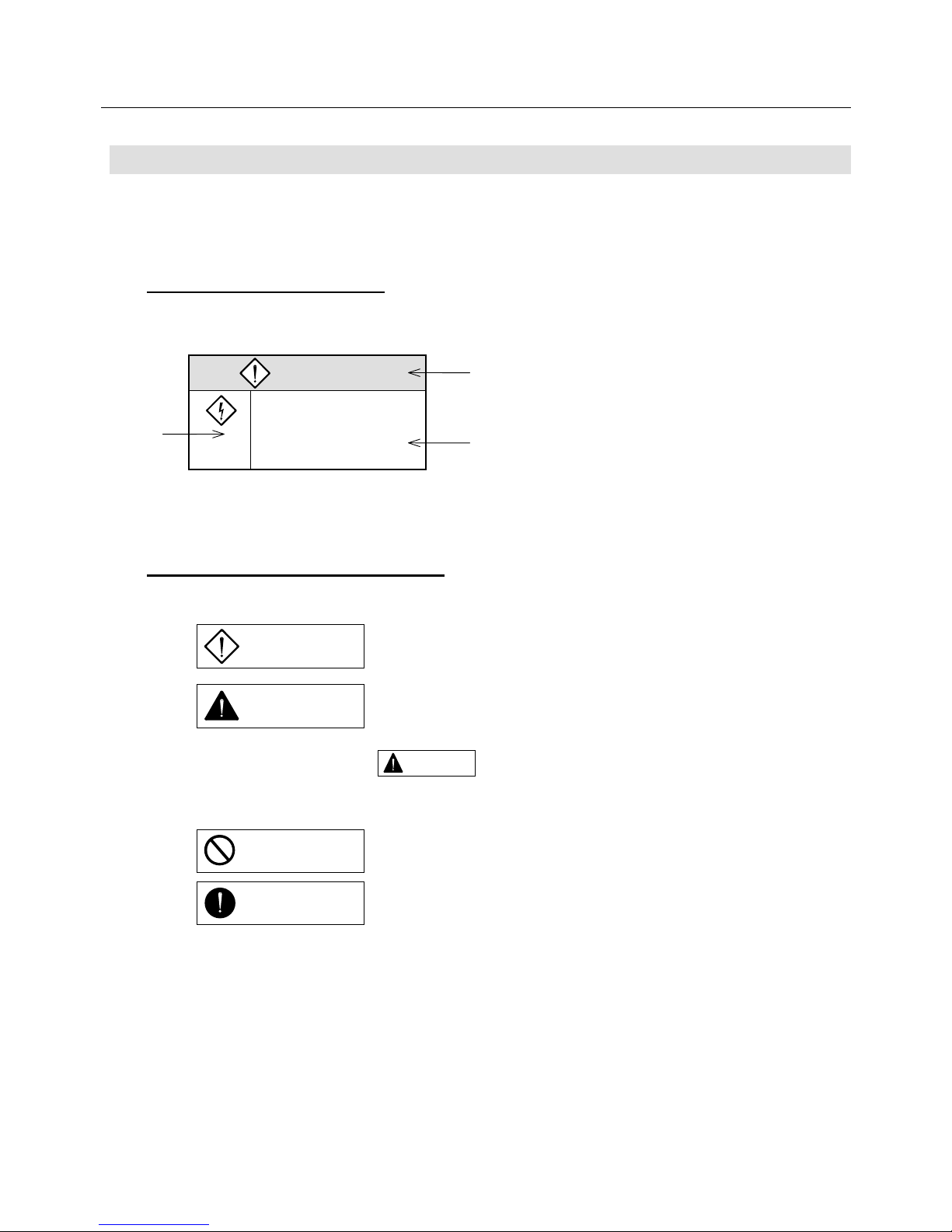
0.3.1 Details of Indications
Section 0.4 describes as follow s:
① : Rank of cautions on safety
② : Symbolic indication
③ : Meaning of each symbolic indication
0.3.2 Rank of Cautions on Safety
Cautions are divided into the following four ranks:
①
Incorrect operation may result in such a dangerous situation as
death or serious injury.
②
Incorrect operation may result in such a dangerous situation as
medium or slight injury or may result in only physical damage.
Note that some indications with may lead to serious results depending on situations.
Since any indications are important, be sure to observe them.
③ What should not be done are indicated.
④ What should be done by all means are indicated.
DANGER
1. The amplifier inside
①
②
③
DANGER
CAUTION
PROHIBITION
COMPULSION
CAUTION
0. SAFETY PRECAUTIONS
0-4
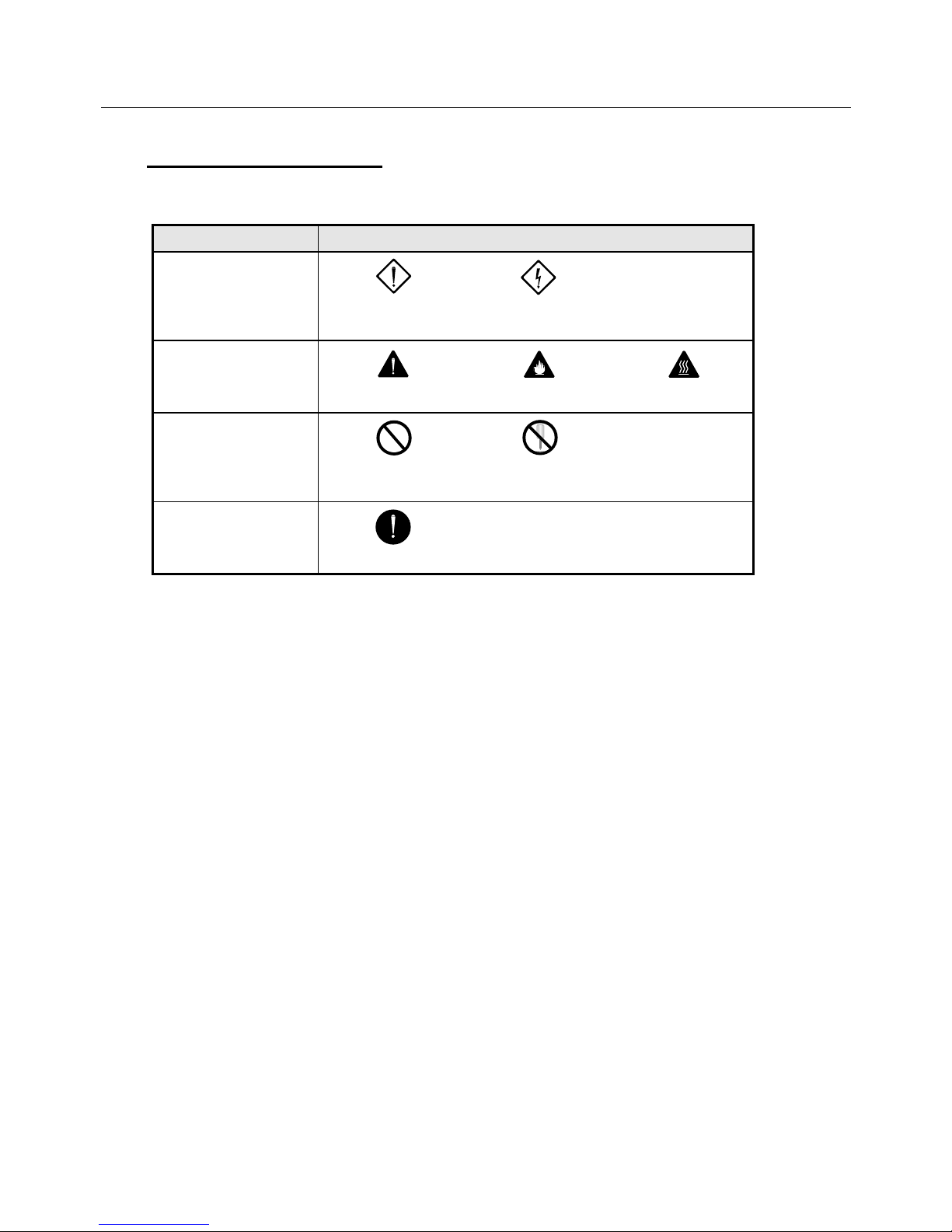
0.3.3 Symbolic Indication
Symbolic indications are divided into the following eight kinds:
Kinds of symbols Example of symbols
Symbolic indications of
danger
DANGER,
INJURY
ELECTRIC
SHOCK
Symbolic indications
calling attention
CAUTION
FIRE
BURN
Symbolic indications
prohibiting actions
PROHIBITION
PROHIBITION OF
DISASSEMBLING
Symbolic indication
urging actions
MANDATORY
0. SAFETY PRECAUTIONS
0-5
0.4 Cautions on Safety
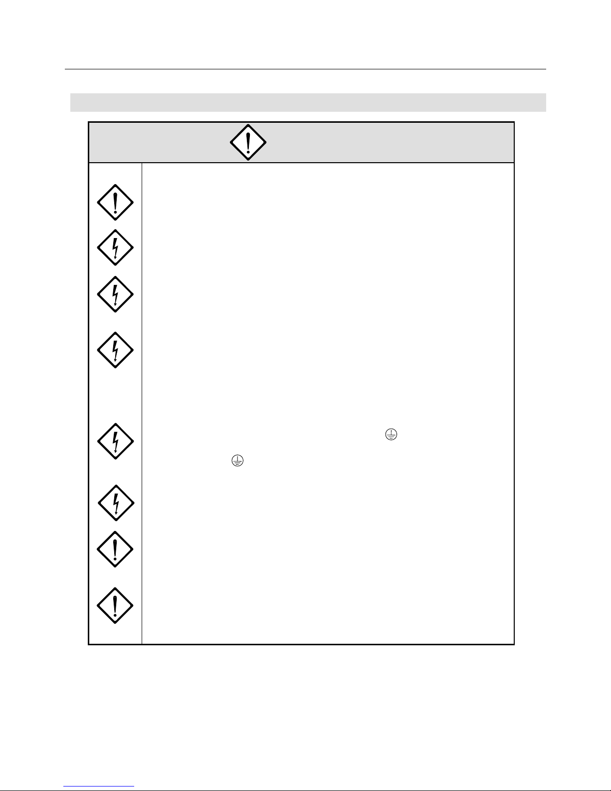
DANGER
<General>
1. Don't operate the system in explosive environment, or you may be injured or fire
may occur.
2. Never touch any inside part of the amplifier, or you may be struck by electricity.
3. Don't arrange wires nor conduct maintenance work and inspection under a
hot-line condition.
Be sure to turn the power off more than 5 minutes in advance.
Otherwise, you may be struck by electricity.
4. Ask experts in respective fields for transportation, installation, wiring, operation,
maintenance and inspection.
Persons without expertise may receive electric shocks, be injured or fire may
occur.
<Wiring>
5. Be sure to ground the PE (protective earth) terminal of the amplifier.
The grounding terminal of the motor must be connected to the PE (protective
earth) terminal of the amplifier. Otherwise, an electric shock may occur.
6. Don't damage cable, stress them abnormally, place heavy items on them nor get
them caught between other parts or devices.
Otherwise, an electric shock may occur.
7. Be sure to connect the power cable in accordance with the connection diagram
or the User's Manual.
Otherwise, you may be struck by electricity, or fire may occur.
8. Since no fuse is built into the main power supply input terminals (R, S and T) of
the amplifier, be sure to insert a UL-approved circuit breaker or fast-blown fuse to
the amplifier power supply input wiring to protect it and its peripherals.
0. SAFETY PRECAUTIONS
0-6
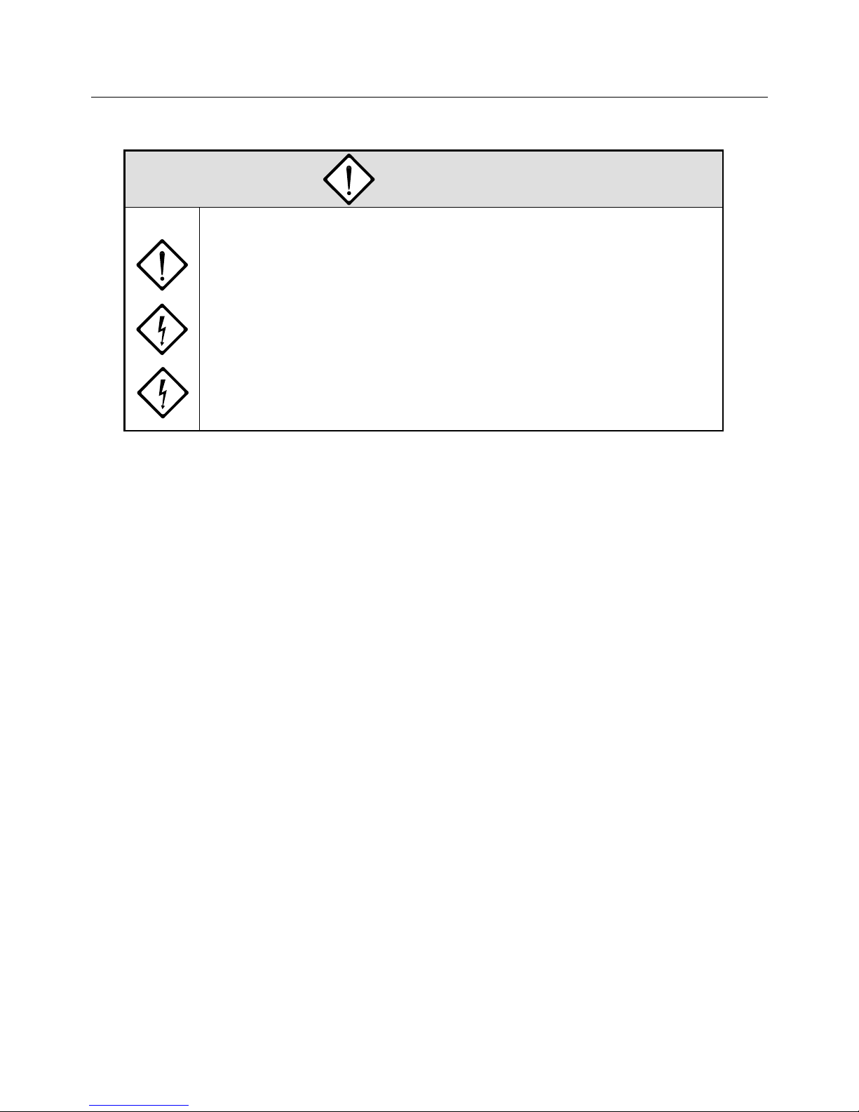
DANGER
<Operation>
9. During operation, never touch the motor rotator, or you may be injured.
10. While the power is supplied, never approach nor touch terminals, or you may be
struck by electricity.
11. While the power is supplied, never remove any terminal cover, or you may be
struck by electricity.
0. SAFETY PRECAUTIONS
0-7
CAUTION
<General>
1. Before installation, operation, maintenance and inspection, be sure to read the
User's Manual and follow instructions detailed in the manual.
Otherwise, you may be struck by electricity or be injured, or fire may occur.
2. Don't use the amplifier and the motor in any situations where the specifications
are not fully satisfied.
Otherwise, you may be struck by electricity or injured, or they may be damaged.
3. Don't use the amplifier and the motor if they are damaged.
Otherwise, you may be injured or fire may occur.
4. Use the amplifier and the motor only in the combination specified, or fire or a
trouble may occur.
5. Note that the amplifier, the motor and their peripheral equipment are heated to
high temperatures.
Don't touch them, or you may be burnt.
<Unpacking>
6. Check which side is up before unpacking, or you may be injured.
7. Check if what you have received are as per your order.
Installation of an incorrect product may result in injury to you or breakage of the
product.
8. Don't apply static electricity to the motor sensor terminal, or the motor may get
out of order.
0. SAFETY PRECAUTIONS
0-8
CAUTION
<Wiring>
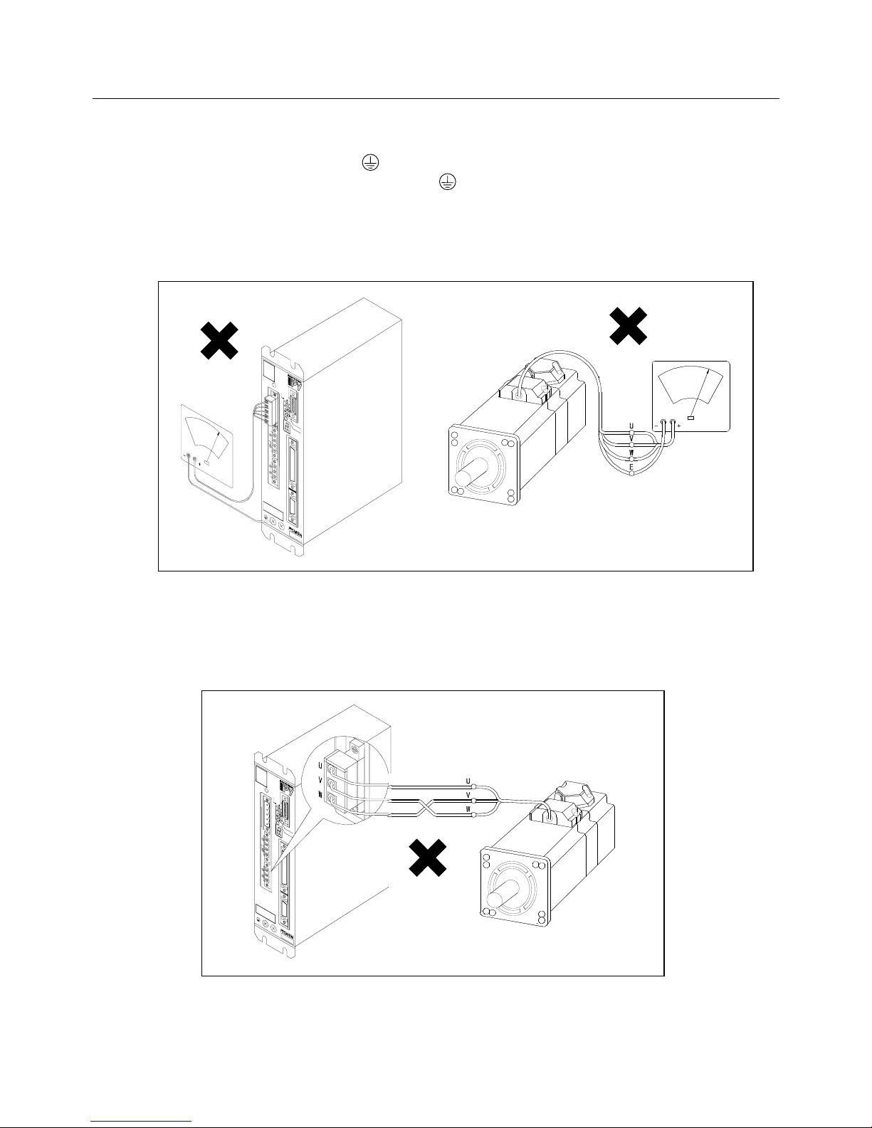
9. Don't measure insulation resistance and dielectric strength, or these units may
be damaged.
When you have to measure them, please contact us.
10. Arrange cables in accordance with the Technical Standard for Electric Facilities
and the Extension Rules.
Otherwise, cables may be burnt and fire may occur.
11. Arrange cables correctly and securely, or the motor may run away and you may
be injured.
12. Don't apply static electricity or high voltage to the motor sensor terminal, or the
motor may get out of order.
<Installation>
13. Don't climb up these units nor place heavy substance on them, or you may be
injured.
14. Don't stop the air inlets and outlets nor put foreign matters in them, or fire may
occur.
15. Be sure to observe the direction of installation, or a trouble will occur.
16. Decide the distances between the amplifier, the inside surface of the control
panel and other equipment in accordance with the User's Manual.
Otherwise, troubles may occur.
17. Don't shock these units badly, or they may be get out of order.
18. During installation, take an extreme care not to drop nor overturn these units, or
you may face serious dangers.
When raising the motor, use the lifting bolt if it is fitted.
19. Never install these units where they are exposed to splash of water, in corrosive
or inflammable gas atmosphere or near combustibles.
Otherwise, fire may occur or they may get out of order.
20. Install them to any of nonflammables like metal, or fire may occur.
0. SAFETY PRECAUTIONS
0-9
CAUTION
<Operation>
21. This motor is not equipped with any protective device.
So, protect it with an overcurrent device, an earth leakage breaker, a thermal
cutout or an emergency stop device.
Otherwise, you may be injured or fire may occur.
22. During the power is supplied or for a while after the power is turned off, don't
touch the amplifier radiator, the regenerative resistor and the motor because they
are or have been heated to high temperatures.
Otherwise, you may be burnt.
23. When any trouble has occurred, stop operating the system immediately, or you
may be struck by electricity or injured, or fire may occur.
24. An extreme adjustment change will make the system operate unstably. Never
make such a change, or you may be injured.
25. To check operation of the system in a trial run, fix the motor and separate it from
the mechanical system.
Otherwise, you may be injured.
After the trial run, mount it on the system.
26. The holding brake is not a stopping device to operate the system safely.
So, install a stopping device to the system for the purpose, or you may be
injured.
27. When an alarm occurs, remove the cause and check that the system is in safety.
Then, reset the alarm and resume the operation.
Otherwise, you may be injured.
28. When the power is restored after momentary interruption, don't approach the
system because it may suddenly start again.
(Design the system so that the operator can remain safe even if it may start
again.)
Otherwise, you may be injured.
29. Check that the power supply specification is normal.
Otherwise, troubles may occur.
0. SAFETY PRECAUTIONS
0-10
CAUTION
<Maintenance>
30. Since the amplifier frame is heated to high temperature, beware of it at the time
of maintenance and inspection, or you may be burnt.
31. The electrolytic capacitor inside the amplifier is recommended to be replaced
with a new one every five years for preventive maintenance providing that the
yearly ambient temperature is 40°C.
The expected life of the cooling fan motor is 10 years at the yearly ambient
temperature of 40°C. Regular replacement is recommended.
32. In case of repair, please contact us.
If these units are disassembled by yourself, they may malfunction.
<Transportation>
33. During transportation, take an extreme care not to drop nor overturn these units,
or you may face serious dangers.
34. During transportation, don't catch cables and the motor shaft, or these unit may
get out of order or you may be injured.
<Disposal>
35. Dispose of the amplifier and the motor as general industrial wastes.
0. SAFETY PRECAUTIONS
0-11
PROHIBITION
<Storage>
1. Don't store these units where they are exposed to water, rain drops, hazardous
gas or liquid.
Otherwise, they will get out of order.
<Operation>
2. The built-in brake of the motor is for holding and should not be used for braking
in general.
If used for braking, the brake will be broken.
<Maintenance>
3. Don't overhaul the system, or fire will occur and you will be struck by electricity.
<General>
4. Do not remove the nameplate.
0. SAFETY PRECAUTIONS
0-12
MANDATORY
<Storage>
1. Store these units where they are not exposed to direct sunlight and in the
specified ranges of temperature and humidity {–20°C to +65°C, below 90%RH
(without dew condensation)}.
2. When the amplifier was stored for a long period (over 3 years as a guide), please
contact us for how to treat it.
When it is stored for a long time, the electrolytic capacitor capacity will decrease
and any trouble may occur.
<Operation>
3. Install an emergency stop circuit outside the system so that operation can be
stopped immediately and that the power supply can be shut off.
4. When the alarm generates, assemble the safety circuit outside of the amplifier.
Running away, injury, burning, fire, and secondary damage may be caused.
5. Operate the system within the specified ranges of the temperature and humidity
(see below).
Amplifier: Temperature = 0 to 55°C, Humidity = 90% RH or lower (no dew
condensation)
Motor: Temperature = 0 to 40°C, Humidity = 90% RH or lower (no dew
condensation)
<Transportation>
6. Overloaded products will collapse.
So, load them in accordance with the indication on the outer cases.
7. Use the lifting bolts on motors for carrying motors only and don't use them for
carrying machines.

1. BEFORE OPERATION
1-1
BEFORE OPERATION
1.1 Precaution on Unpacking ............................................................. 1-2
1.2 Confirmation of the Product .........................................................1-2
1.3 Precautions on Operation ............................................................ 1-2
1.4 How to Read Model Numbers...................................................... 1-6
1.4.1 Model Number of Servomotor ........................................... 1-6
1.4.2 Model Number of Servo Amplifier ..................................... 1-7
1.5 PY2 Servo Amplifier Standard Combination ................................ 1-8
1.6 Flowchart for Determining Servomotor
Model Number ............................................................................. 1-9
1. BEFORE OPERATION
1-2
Please operate this system taking the contents of the following description into consideration.
A misoperation will lead to an unexpected accident or damage.
1.1 Precaution on Unpacking
When unpacking this product after purchasing, care is needed to the following.
• When unpacking the Servo Amplifier, don't touch its printed circuit boards in any case.
1.2 Confirmation of the Product
Check the following after receiving the product. Contact us if any abnormality is detected.
• Check if the model numbers of the Servomotor and the Servo Amplifier match those of the ordered ones
(the numbers are described after "MODEL" on the main nameplate).
• Check the appearance of the Servomotor and the Servo Amplifier to confirm that they are free from any
abnormality such as breakage or lack of parts.
• Check that all screws on the Servomotor and the Servo Amplifier are tightened properly.
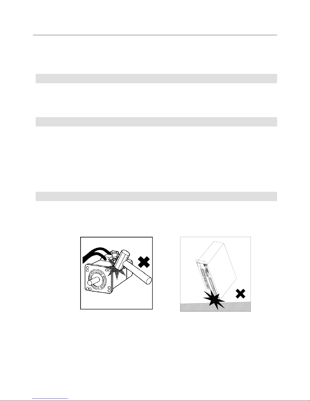
1.3 Precautions on Operation
Take care the following during operation.
• At installation, don't give shocks to the Servomotor and the Servo Amplifier, or they may break.
In particular, handle the Servomotor carefully since it is provided with a sensor.
1. BEFORE OPERATION
1-3
• Be sure to use a power supply within the specified range.
200 VAC input type: PY2A…, PY2B…
200 VAC to 230 VAC (+10%, −15%) 50/60 Hz
100 VAC input type: PY2E…, PY2F…
100 VAC to 115 VAC (+10%, −15%) 50/60 Hz
If a power supply other than the above is used, an accident may result.
• When a surge voltage is produced in the power supply, connect a surge absorber or others between the
powers to absorb the voltage before operation.
Otherwise malfunction or breakage may result.
• Turn the power on and off during maintenance and inspection after safety (such as the situation of the
load) is completely checked. If the power is turned on or off during the load is applied, an accident or
breakage may result.
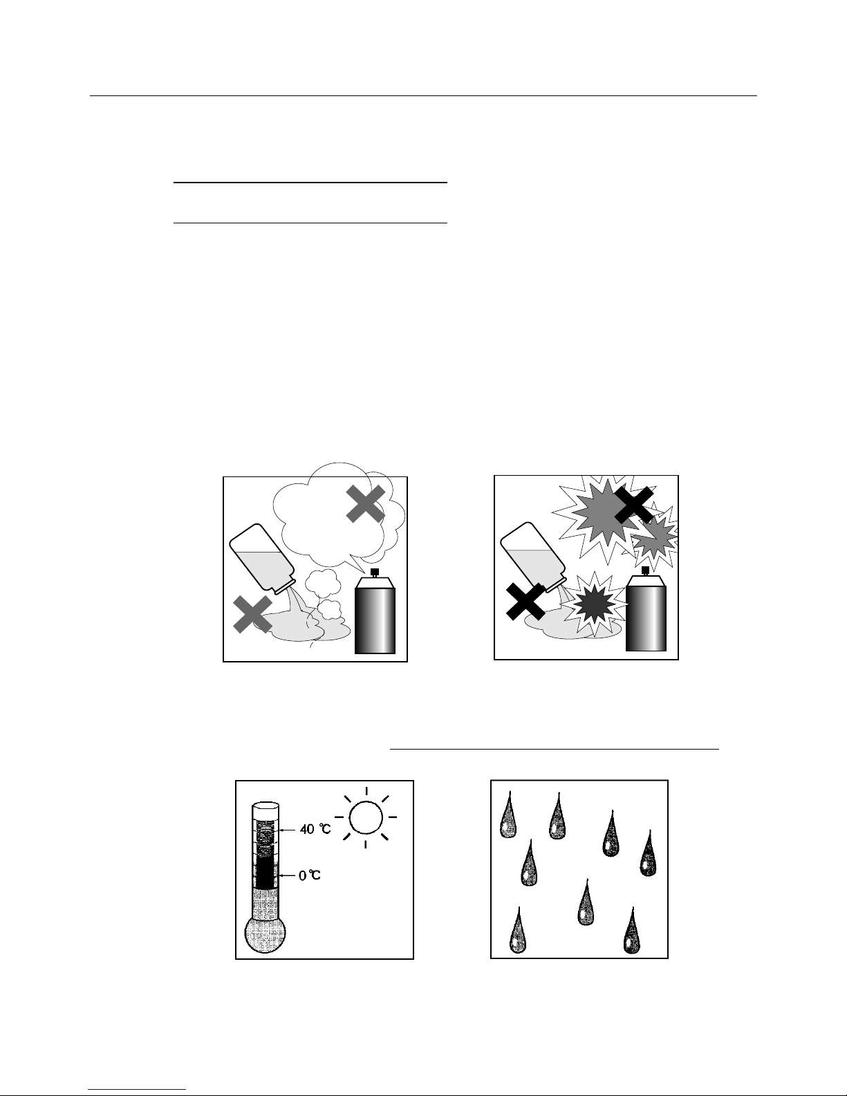
• Never use this product where corrosive (acid, alkali, etc.), flammable or explosive liquid or gas exists to
prevent it from deforming or breaking.
• Never use this product where flammable or explosive liquid or gas exists since the liquid or the gas may
be ignited, causing great danger.
Corrosives
Gas
Acid/Alkali
Flammables
Explosives
• Use this product within the ambient temperature range from 0°C to 40°C (0°C to 55°C for the Servo
Amplifier) and below the relative humidity limit of 90%.
• The Servomotor and the Servo Amplifier should be kept away from water, cutting fluid or rainwater
.
Otherwise electric leakage or and electric shock may result.
1. BEFORE OPERATION
1-4
• For operating safety, check that the Servo Amplifier is grounded by at least a class 3 (less than 100Ω) of
the PE (protective earth) terminal . In addition, the grounding terminal of the Servomotor must be
connected to the PE (protective earth) terminal .
• Never perform a withstand voltage or a megger test of the Servomotor or the Servo Amplifier.
In this product, 0V and the main body is earthed by the capacitor.
If such test is necessary, consult with us.
• Perform correct wiring by referring to the chapter "4. Wiring".
Wrong wiring may cause Servomotor's or amplifier's breakage.
• Since the "P" series Servomotor is not an induction motor, the direction of revolution cannot be changed
by swapping the phases.
To change the direction, use the remote operator.
• For safety operation, be sure to install a surge absorber on the relay, electromagnetic contactor,
induction motor and brake solenoid coils.
1. BEFORE OPERATION
1-5
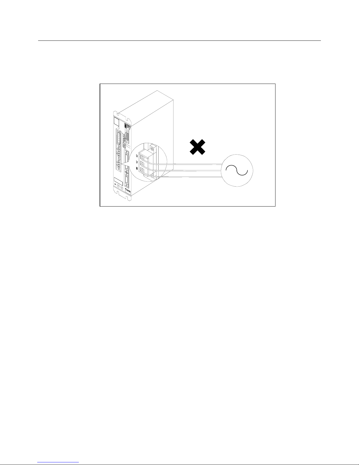
• Connect a power supply within the specified range to the Servo Amplifier’s R, S, T terminals respectively.
When a power supply out of the specified range is used, install a transformer.
If a commercial power supply is applied to the U, V or W terminal, the amplifier will break.
Commercial
power supply

1. BEFORE OPERATION
1-6
1.4 How to Read Model Numbers
1.4.1 Model Number of Servomotor
1. BL series
P10...P1 series
P20...P2 series
P30...P3 series
P50...P5 series
P60...P6 series
P80...P8 series
2. Indicates the BL motor
3. Indicates flange square size
03…35 mm 04…40 or 42 mm 05…54 mm
06…60 mm 07…76 mm 08…80 or 86 mm
13…130 mm 15…150 mm 18…180 mm
22…220 mm
4. Indicates rated output
○○○ = ○○○ × 10 w
5. Maximum revolution speed
S…1000 min
−
1
M…1500 min
−
1
B…2000 min
−
1
R…2500 min
−
1
H…3000 min
−
1
D…4500 min
−
1
P…4500 min
−
1
6. Equipping of holding brake
X…Not equipped. B…Equipped. (90V) C…Equipped. (24V)
7. Type of detector
S… Wiring-saved incremental encoder
J… Absolute encoder with the motor flange square of 60 mm or less;
Request signal-unavailable type.
A… Absolute encoder with the motor flange square of 76 mm or more;
Request signal-unavailable type.
N... ABS-RII; Super-capacitor-unavailable, request signal-available type.
V... ABS-RII; Super-capacitor-built-in, request signal-available type.
8. Specification identification
00… Standard motor
B
○○○ ○○○ △ □ ◇○○ ▽▽
The design revision order is indicated by an alphabet at the end of Lot No. on the
nameplate.
1. BEFORE OPERATION
1-7
1.4.2 Model Number of Servo Amplifier
1. Indicates a PY2 servo amplifier
2. Type of power unit
A… For 200 VAC input, with dynamic brake
B… For 200 VAC input, without dynamic brake
E… For 100 VAC input, with dynamic brake
F… For 100 VAC input, without dynamic brake
3. Amplifier capacity
015… 15A 030… 30A 050...50A
4. Hardware type of control unit
A... Wiring-saved incremental encoder (INC-E) or request
signal-unavailable absolute encoder (ABS-E)
H... Request signal-available absolute sensor (ABS-RII)
P… Wiring-saved absolute sensor (ABS-E.S1)
5. Optional specifications of power supply input and power sections
6. Applicable motor
(For details, refer to the standard combination table on the next page. )
Example M1…P50B03003D□□□□ PA…P60B13050H□□□□
7. Type of applicable sensor
1... Wiring-saved incremental encoder (2000P/R)
2... Wiring-saved incremental encoder (6000P/R)
3... Request signal-unavailable absolute encoder (ABS-E, 2048P/R)
6... Request signal-available absolute encoder (ABS-RII, 8192P/R)
W…Wiring-saved absolute sensor (ABS-E.S1, 32768 dividing)
8. Interface specification
S…Speed control type. T…Torque control type. P…Position control type.
X…S-T switch type Y…P-T switch type U…P-S switch type V…Internal Speed control type
9. Discrete specification
00… Standard product
00
▽△
XX 0
PY2
○○○□
A
• The design revision order is indicated by an alphabet at the end of Lot No. on the
nameplate.
• In some Servo Amplifiers, the items 6 to 9 above are not specified. Servo Amplifiers
having the following model numbers can be used after specifying the parameters such as
motor, sensor and interface.
PY2A015A2 PY2A030A2 PY2A050A6 PY2E015A3 PY2E030A3
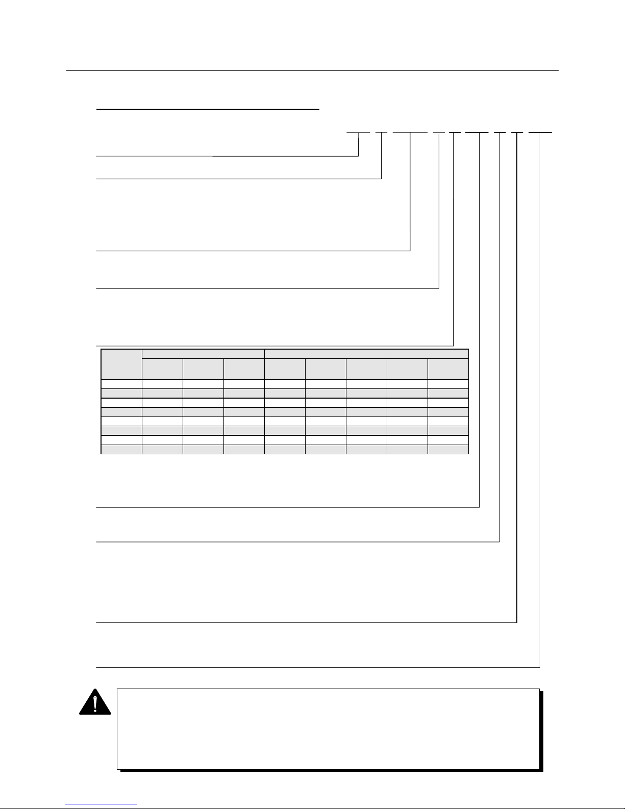
Model code Contents of specifications Support by power section type and amplifier capacity *3
Built-in
regenerative
resistor *1
RDY output
*2
Main circuit
power supply
type
PY2A015 PY2A030 PY2A050 PY2E015 PY2E030
0 × ○ 3-phase ○ ○ × × ×
1 × ○ Single phase ○ ○ × ○ ○
2 × × 3-phase ○ ○ × × ×
3 × × Single phase ○ ○ × ○ ○
4 ○ ○ 3-phase △ *4 ○ ○ × ×
5 ○ ○ Single phase △ *4 ○ ○ △*4 ○
6 ○ × 3-phase △ *4 ○ ○ × ×
7 ○ × Single phase △ *4 ○ ○ △*4 ○
*1: Built-in regenerative resistor: ○= with built-in regenerative resistor, ×= without built-in regenerative resistor
*2: RDY output: ○= with RDY output, ×= without RDY output
*3: Support by power section type and amplifier capacity ○= supportive, ×= not supportive
*4: For 15A regenerative resistor built-in type, configuration (dimension) of Amp. partially differs from standard.
1. BEFORE OPERATION
1-8
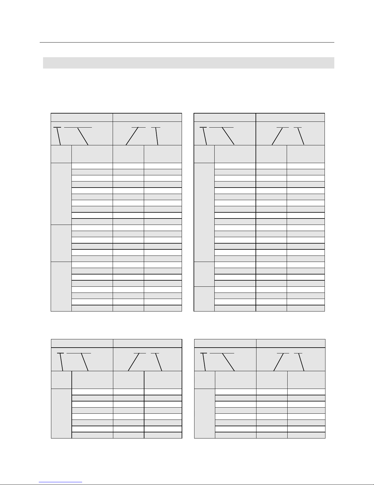
1.5 "PY2" Servo Amplifier Standard Combination
Check the model numbers of the motor and the amplifier on the combination table below.
If the combination is different, the system will not function properly.
Table1-1 "PY2" Servo Amplifier Standard Combination Table (200 VAC input type)
Table1-2 "PY2" Servo Amplifier Standard Combination Table (100 VAC input type)
Servomotor Servo Amplifier
P☆B○○○○○○□◇▽▽
PY2A○○○A2XX△▽00
Series
Flange square
Rated output
Maximum speed
Amplifier
capacity
Motor type
03003D 015 M1
04006D 015 M2
04010D 015 M3
05005D 015 M4
05010D 015 M5
05020D 015 M6
07020D 015 M8
07030D 015 M9
07040D 030 MA
08040D 030 MB
08050D 030 MC
08075D 050 MD
08100D 050 ME
08075H 030 MF
08100H 030 MG
P50
13050H 030 PA
13100H 050 P1
13150H 050 P2
P60
15075H 030 R2
18120H 050 R3
P80
Servomotor Servo Amplifier
P☆B○○○○○○□◇▽▽
PY2A○○○A2XX△▽00
Series
Flange square
Rated output
Maximum speed
Amplifier
capacity
Motor type
10030H 030 11
10075H 030 12
13050H 030 13
13100H 050 14
13150H 050 15
13050B 030 1A
13100B 030 1B
13150B 050 1C
18200B 050 1D
P10
10100D 050 21
10150D 050 22
10100H 030 28
10150H 050 29
10200H 050 2A
P20
04003D 015 N1
04005D 015 N2
04010D 015 N3
06020D 015 N4
06040D 030 N5
08075D 030 N6
P30
Servomotor Servo Amplifier
P☆B○○○○○○□◇▽▽
PY2E○○○A3XX△▽00
Series
Flange square
Rated output
Maximum speed
Amplifier
capacity
Motor type
03003P 015 MH
04006P 015 MJ
04010P 015 MK
05005P 015 ML
05010P 015 MM
05020P 030 MN
07020P 030 MR
P50
07030P 030 MS
Servomotor Servo Amplifier
P☆B○○○○○○□◇▽▽
PY2E○○○A3XX△▽00
Series
Flange square
Rated output
Maximum speed
Amplifier
capacity
Motor type
04003P 015 NA
04005P 015 NB
04010P 015 NC
06020P 030 ND
P30
1. BEFORE OPERATION
1-9
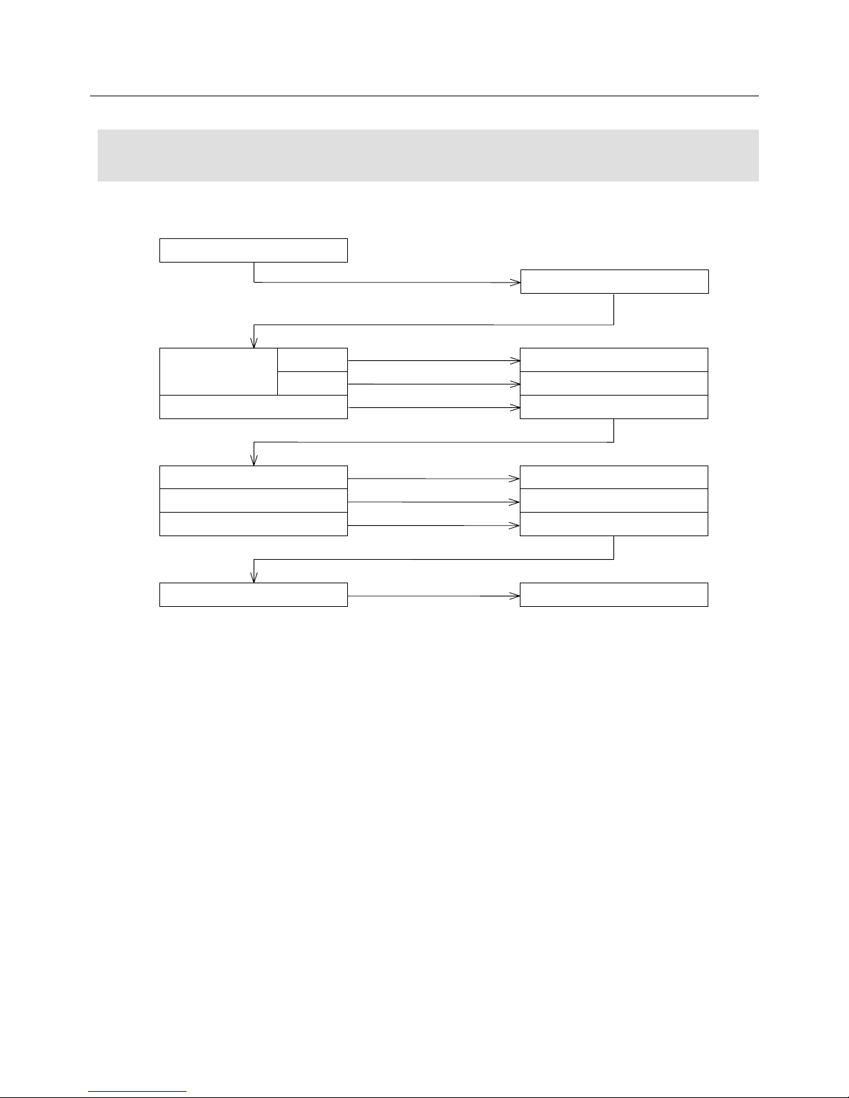
1.6 Flowchart for Determining Servomotor
Model Number
Refer to the following flowchart to determine the Servomotor model number.
Select Servomotor capacity.
With brake
90 V
24 V
Without brake
Determine capacity and
maximum speed.
Add B to the end.
Add C to the end.
Add X to the end.
P50B08100D
P50B08100DB
P50B08100DC
P50B08100DX
P50B08100DXS
P50B08100DXA
P50B08100DXS00
P50B08100DXN
Incre. 2000P/R
Standard specifications
Absol. 2048 divisions
ABS-RII 8192 divisions
Ex.
Ex. Sensor type
Add S to the end.
Add 00 to the end.
Consult with us for special
requirements.
Add A to the end.
Add N to the end.
 Loading...