

Sanyo SU30 - PLC SVGA LCD Projector,SU30 Owner's Manual

Please read "Notes on Safety" for the Multimedia Projector Owner's Manual and the Smoke Resistant Unit
Owner's Manual before commencing this operation.
Disconnect the power supplies of the Multimedia Projector and the Smoke Resistant Unit, confirm that the
temperature of the Multimedia Projector has fallen, and perform the replacement by carrying out the
following steps.
Place the smoke resistant unit on a flat table so that
the edge of the front cover protrudes slightly over
the edge of the table.
Note: Please ensure that there is nothing projecting
from the table underneath the Smoke
Resistant Unit which may harm the lower
surface and in turn cause damage to the
indicator.
Take out the three M4 flat countersunk head screws
fixing the front cover.
Two projections fixing the front cover are provided
on the inside of the bottom surface of the Smoke
Resistant Unit both at distances of 136mm from the
sides of the unit. Pull the front cover towards
yourself in a direction parallel with the table while
pushing the positions at which the projections are
located upwards from below, so as to remove the
front cover.
Note: Do not tilt the front cover when pulling it to
remove it, as this may damage the projections
which will make it impossible to put the front
cover back on again.
Take out the three M3 screws on the reverse side of
the front cover so as to remove the thick-type
exhaust duct.
1
2
3
4
Manual For Providing A Smoke Resistent Unit
Manual For Providing A Smoke Resistent Unit
With A Replacement Louver (Thin-type Exhaust Duct)
With A Replacement Louver (Thin-type Exhaust Duct)
Manual For Providing A Smoke Resistent Unit
With A Replacement Louver (Thin-type Exhaust Duct)
FRONT COVER
136mm
136mm
PROJECTIONS
THREE M3 SCREWS
REVERSE SIDE
OF THE FRONT COVER
THICK-TYPE EXHAUST DUCT
M4 FLAT COUNTERSUNK HEAD SCREWS
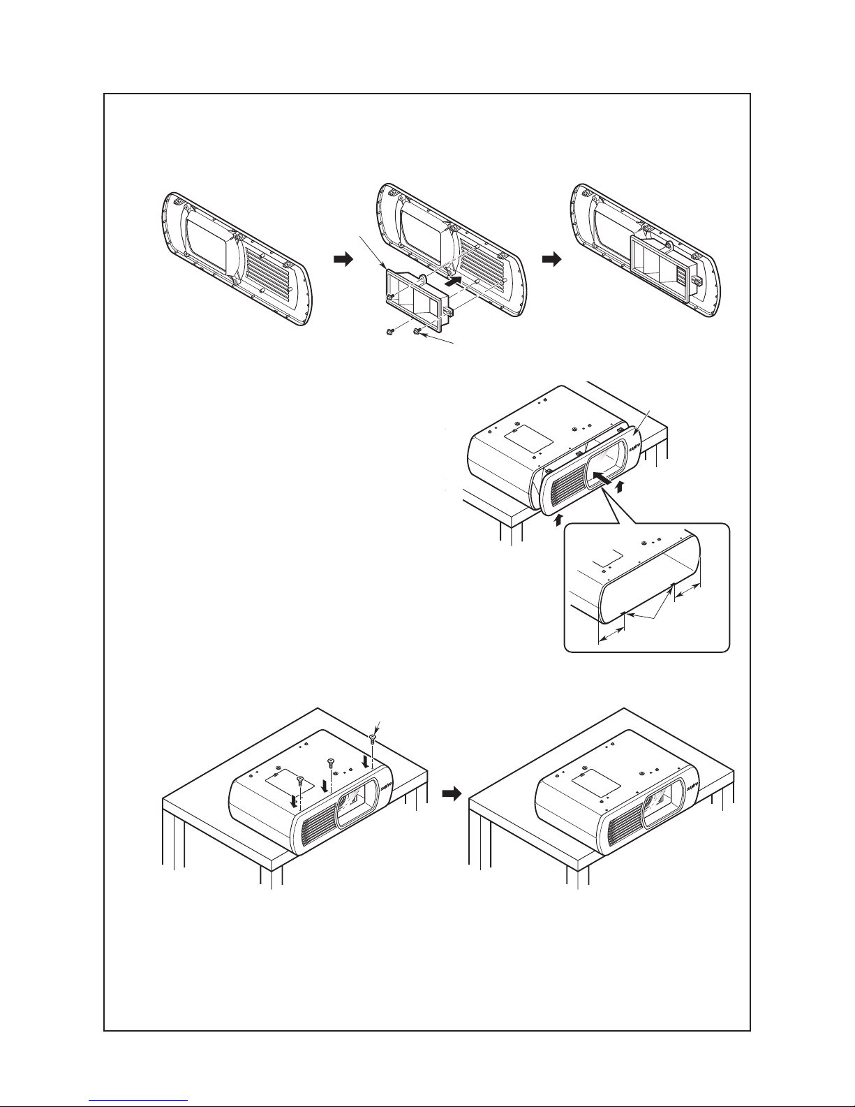
Fix the thin-type exhaust duct in the position of the
thick-type exhaust duct using the three M3 screws.
Replace the Multimedia Projector installed in the
Smoke Resistant Unit with a Multimedia Projector
compatible with the thin-type exhaust duct.
Place the front cover vertically on the Smoke
Resistant Unit. Then insert the front cover into the
Smoke Resistant Unit while pushing upwards from
below at the positions of the lower projections.
Note: Do not tilt the front cover when inserting it, as
this may damage the projections which will
make it impossible to put the front cover back
on again.
Fix the front cover to the Smoke Resistant Unit
using the three M4 flat countersunk head screws
removed previously.
Replacement with the thin-type exhaust duct is now complete.
Return the Smoke Resistant Unit to it's original position and turn the power supply on.
5
6
7
8
9
136mm
136mm
FRONT COVER
PROJECTIONS
M4 FLAT COUNTERSUNK
HEAD SCREWS
THREE M3 SCREWS
THIN-TYPE
EXHAUST DUCT
REVERSE SIDE
OF THE FRONT COVER
 Loading...